Page 1
The impacts of hydraulic fracturing on the environment
Compiled by:
Annamária Nádor
Project leader
Co-authors: László Bereczki, Róbert Csabafi, Ágnes Cserkész-Nagy, Tamás
Fancsik, Tamás Kerékgyártó, Attila Csaba Kovács, Éva Kun, Gábor Markos,
Annamária Nádor, Teodóra Szőcs, László Zilahi-Sebess
Budapest, 1 June 2015
Page 2
1
TABLE OF CONTENTS
1 Introduction ..................................................................................................................... 1
2 Hydraulic fracturing....................................................................................................... 3 2.1 The operation of fracturing ...................................................................................... 4 2.2 Composition and quantity of fracturing fluid .......................................................... 6 2.3 Proppants ............................................................................................................... 12 2.4 Fracturing fluids and proppants used in Hungarian practice ................................. 14 2.5 The role of rock mechanics and stress field in the development of fractures ....... 16
2.6 The monitoring of fracturing process .................................................................... 19 2.7 Geothermal hydraulic fracturing ........................................................................... 19
3 Environmental impacts of hydraulic fracturing ........................................................ 22 3.1 The impact of hydraulic fracturing on surface and groundwater .......................... 25
3.1.1 Water acquisition ....................................................................................... 25
3.1.2 Sources of pollution and their potential spread ......................................... 26
3.1.3 Potential environmental risks on the surface caused by the storage of the
recovered fracturing fluid ...................................................................................... 28 3.1.4 The role of hydrogeological monitoring .................................................... 29 3.1.5 Other hydrogeological aspects ................................................................... 29
3.2 Earthquake risk (induced seismicity) .................................................................... 30
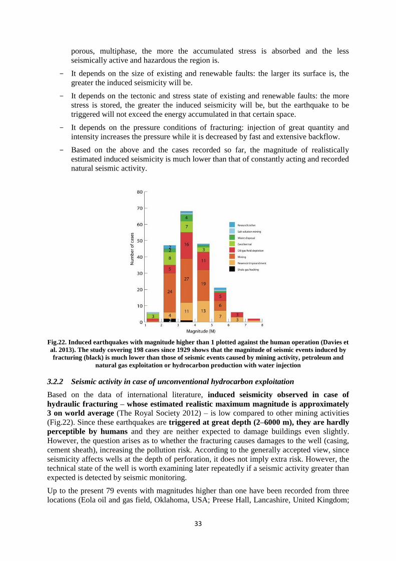
3.2.1 Induced seismicity – general review .......................................................... 32 3.2.2 Seismic activity in case of unconventional hydrocarbon exploitation ...... 33 3.2.3 Seismic activity in case of geothermal systems ......................................... 36
3.2.4 The role of seismic monitoring .................................................................. 37
4 Detailed analysis of Hungarian pilot areas ................................................................. 40 4.1 Area selection ........................................................................................................ 40 4.2 Methodology ......................................................................................................... 40 4.3 Derecske Trench .................................................................................................... 42
4.3.1 Geological structure ................................................................................... 42
4.3.2 Hydrogeological conditions ....................................................................... 49 4.3.3 Hydraulic fracturing and evaluation .......................................................... 61
4.3.3.1 The results of microseismic monitoring ........................................ 62
4.3.3.2 The spatial position of induced fractures, potential pollution
spreading routes and connections ................................................................ 65
4.4 Battonya High ........................................................................................................ 72 4.4.1 The geological structure ............................................................................ 72 4.4.2 Hydrogeological conditions ....................................................................... 79
4.4.3. Hydraulic fracturing and evaluation ......................................................... 90
5 Summary........................................................................................................................ 92 6 References ...................................................................................................................... 98
Page 3
1
1 INTRODUCTION
In Hungary hydraulic fracturing is a precondition for the exploitation of unconventional
hydrocarbon resources and the geothermal energy production using EGS technology. Due to
the fracturing licensing problems, in 2014 a dialog started within an inter-ministerial
committee between the relevant ministries [Ministry of National Development (NFM),
Ministry of Agriculture (FM) and Ministry of Interior (BM)]. The Inter-Ministerial
Committee discussed the viewpoints during several meetings involving the Hungarian Office
of Mining and Geology (MBFH) and the operators concerned.
The current regulatory system applied to hydrocarbons may be significantly altered by the
modification of the Act No. XLVIII. 1993 on Mining (Mining law) coming into force on 11
January 2015. Since then the licencing of hydrocarbon exploitation technology operations
serving the purpose of mineral resource management – including especially hydraulic
fracturing and acidizing, the injection of water and gas, the replenishment of formation energy
– will fall within the competence of mining inspectorate. The main goal of this addition is to
make clear that in case of the licensing of certain technologies the mining inspectorate has
adequate professional background and this way competence. It was necessary because recent
practical experience shows that the competence of environmental, water authority and mining
inspectorate is not unambiguously separated in this respect (whether the scope of the
Governmental Decree No. 219/2004 on groundwater protection covers hydrocarbon reservoirs
as geological formations or not). This has led to legal interpretation problems, disputes and
controversial categorical official bans on several occasions.
In Hungary as well as in Europe the environmental consideration of hydraulic fracturing
is contradictory; therefore its regulation and official licensing are sources of conflicts.
Environmental authorities usually form an opinion of the particular environmental impacts
(first of all the risk of an earthquake triggered by fracturing and the potential pollution of
groundwater) by international examples, although some of these (Ewen et al. 2012) draw
attention to the importance of the analyses of local circumstances and the regulatory steps
determined based on those. However, the majority of the international examples referred to
in numerous domestic analyses are not comparable with the Hungarian conditions
considering their geological circumstances and technical level so the consequences stated
in those analyses cannot be considered authoritative for Hungary. For instance, the most cited
American shale gas deposits being exploited are from so-called Palaeozoic rocks at depth of
1500–2500 m, usually in rising state, the exploitation of which is carried out in huge fields
consisting of several thousands of wells. Whereas Hungarian shale gas deposits are situated at
depth greater than 3500–4000 m, in young (Tertiary) sediment and basically in falling
geodynamic conditions where the fields would be explored by fracturing a few wells for the
time being. By inaccurate interpretation of international examples misleading information
taken out of their original context can become known publicly, such as “water demand used
for hydraulic fracturing can achieve 15 million litre per fracturing operation, while the amount
of water used for fracturing is enough to meet the annual water demand of 10 000 European
inhabitants” (Aitken et al., 2012).
The objective judgement of the extraordinary complex issue of hydraulic fracturing is
hampered by the fact that although the Hungarian and international “literature” of the topic is
extremely vast, a significant part of them is published without professional revision, and in
many cases can be considered as yellow press articles, presentations, online comment or
“study”. However, in the field of Earth sciences or mining just as in other sciences the
authoritative and scientifically established consequences of a paper published in a scientific
Page 4
2
journal according to the accepted publishing practice (revision) can guarantee (in a way) the
authenticity of the claimed statements. This study attempts to refer to this kind of literature.
For example, the questionnaire-based investigation of the IAH (International Association of
Hydrogeologists) in 2013 did not take a stand on the issue of hydraulic fracturing, however,
drew attention to the importance of area-specific knowledge acquisition (Fig.1).
After a short general overview this study undertakes to analyse the environmental impacts
of hydraulic fracturing and their potential realistic risks first of all based on particular
domestic areas, the geological conditions of the Pannonian basin and the investigation of
the domestic experience so far. The detailed analyses of two domestic pilot areas,
Derecske Trench and Battonya High are at the forefront of this study. These areas were
chosen because both of them allow the concrete analysis of potential environmental impacts
of hydraulic fracturing used for unconventional hydrocarbon extraction in case of Derecske
Trench and for enhanced geothermal systems (EGS) in case of Battonya High, while their
geological setting are different. Another important aspect was that the MOL (Hungarian
hydrocarbon company) placed detailed data on fracturing operation near Berettyóújfalu from
Derecske Trench at disposal as a response to the letter of the Hungarian Office of Mining and
Geology (MBFH) to the Hungarian Mining Association about data request on hydraulic
fracturing. Further reason of the choice was that during the concession procedure so-called
vulnerability and loading capability assessment (Kovács et al. 2013, Zilahi-Sebess et al. 2013)
have been prepared for both areas, which include the areas’ complex assessment focusing on
environmental aspects. All of these data and information were added to the unique, national
geological, geophysical and hydrological spatial database of the Geological and Geophysical
Institute of Hungary (MFGI), and their re-evaluation allowed an integrated interpretation in
which the effective factors, processes, interactions in space and time can be demonstrated
excellently and judged realistically.
Fig.1. The result of the questionnaire-based assessment of the IAH (source: http://iah.org/wp-
content/uploads/2013/11/Results-from-IAH-survey-concerning-Hydraulic-Fracturing.pdf
This study was compiled by the experts (geologists, geophysicists, hydrogeologists) of the
Geological and Geophysical Institute of Hungary. It aims to summarize and formulate in an
understandable way the geological and hydrogeological knowledge needed for the
Page 5
3
independent, sector- and interest-neutral judgement of the environmental impacts of hydraulic
fracturing for decision makers.
2 HYDRAULIC FRACTURING
During fluid mining the fluid (namely petroleum, natural gas and thermal water) is exploited
from underground geological formations so-called reservoirs by means of borings. The
efficiency of this process depends on the permeability of the rocks forming the reservoir. If it
is suitable, the production can operate optimally, without stimulation or using significant
amount of surplus energy. Hydraulic fracturing aims to enhance the output of reservoirs
consisting of compact rocks with low natural permeability in order to increase the quantity
of fluid exploited during the mining. This technology is applied in Hungary also by the
hydrocarbon industry in order to stimulate conventional hydrocarbon deposits for several tens
of years and for the exploration of unconventional hydrocarbons for a few years.
In case of Enhanced Geothermal Systems (EGS), which is considered an immature industrial
technology so far hydraulic fracturing and experiments are carried out for several years on
international level (Breede et al. 2013); in this field there are no domestic experience in the
absence of existing projects. In accordance with these, the study focuses on the analysis of
hydraulic fracturing applied for the exploitation of unconventional hydrocarbons and their
environmental impacts. The considerations on EGS and hydraulic fracturing differing from
the former ones are presented in separated subsections.
Hydraulic fracturing requires interdisciplinary team work (reservoir geology, boring
technology, petrophysics, fluid mechanics, geochemistry, geophysics, environmental
protection etc.). The fracturing characterization of the reservoir also consists of extremely
complicated and complex petrophysical, reservoir mechanical (stress field, Young’s modulus,
fracturing etc.) examinations. Hydrocarbon research companies use sophisticated software to
model and visualize the developing fracture networks.
The first fracturing attempts to stimulate oil wells bored in hard rock were made in the United
States in the 1860s, when liquid nitro-glycerine was used for fracturing. Later in the 1930s
came up to apply acid for fracturing instead of explosive. The first hydraulic fracturing took
place in 1947, in the United States, Kansas. The technology was not successful at first, it
needed further modification, but the Halliburton Company found the idea interesting and
purchased its patent so they improved it. Finally in 1949 two hydraulic fracturing activities
proved to be successful. By the 1960s this technology was a good practice for enhancing the
production of low permeability reservoirs.
In the 1970s and 1980s due to the initiative of the U.S. Department of Energy (DoE), its
research institutes together with private enterprises mapped the American shale gas deposits
and did detailed research on technological developments allowing their exploitation within a
comprehensive research and development programme of almost 20 years. In addition the
American Government supported the applied technologies by tax reductions for nearly two
decades. One of the main reasons of the fast development of the American shale gas
exploitation is the fact that the extracted mineral belongs to the owner of the land, so
landowners were interested in expanding the exploitation and the technology needed for the
exploitation of unconventional hydrocarbons was available for the companies. Nowadays
80% of the operating American wells are fractured, showing that this technology is practically
applied in all cases – in case of conventional and unconventional hydrocarbons.
On the other hand in Europe the fracturing is not widely used because of the diverse
geological settings hampering the exploitation, the high density of population and the higher
Page 6
4
additional costs. In Hungary the technology of hydraulic fracturing is applied successfully
sing 1957 in conventional hydrocarbon (oil, gas) exploitation. The University of Miskolc
published a study on hydraulic fracturing as far back as 1966. Up to the present nearly 2000
hydraulic fracturing activities have been carried out in Hungary while no breakdown or
accident has occurred. 38 wells have been bored in order to research into unconventional
hydrocarbons on six licenced areas, among which 8 wells have been fractured.
2.1 The operation of fracturing
During hydraulic fracturing fluid of adequate quality and quantity is pumped through the
perforation of the well with high water flow (5000–8000 l/min) and under high pressure (700–
1000 bar), resulting in a local fracture system in the reservoir rock. Its extension depends on
the mechanical properties of the rock, the quantity of the fracturing fluid and duration of the
fracturing operation. Approximately 99.5% of the fluid is composed of water and so-called
proppant while about 0.5% consists of further additives (see section 2.2 for further details).
The process of fracturing can be divided into three phases per each fracturing depth. The first
phase is the perforation, the second one is the so-called minifracturing then the main part is
the mainfracturing.
During perforation the casing separating the bore hole from the formation is shot through by
explosive resulting in small holes, in order to open the well towards the formations.
During minifracturing the already perforated formation is exposed to overpressure aiming to
fracture the target zone primarily. This overpressure builds up quickly and it is not long-
lasting. The operation may be accompanied by microseizmic activities since the fracturing of
the rock involves energy release (see section 3.2). Fractures are developing vertically in a
zone ranging from several tens of metres to maximum 100 m typically, while horizontally
their distance from the well is significant and can achieve even several hundreds of metres.
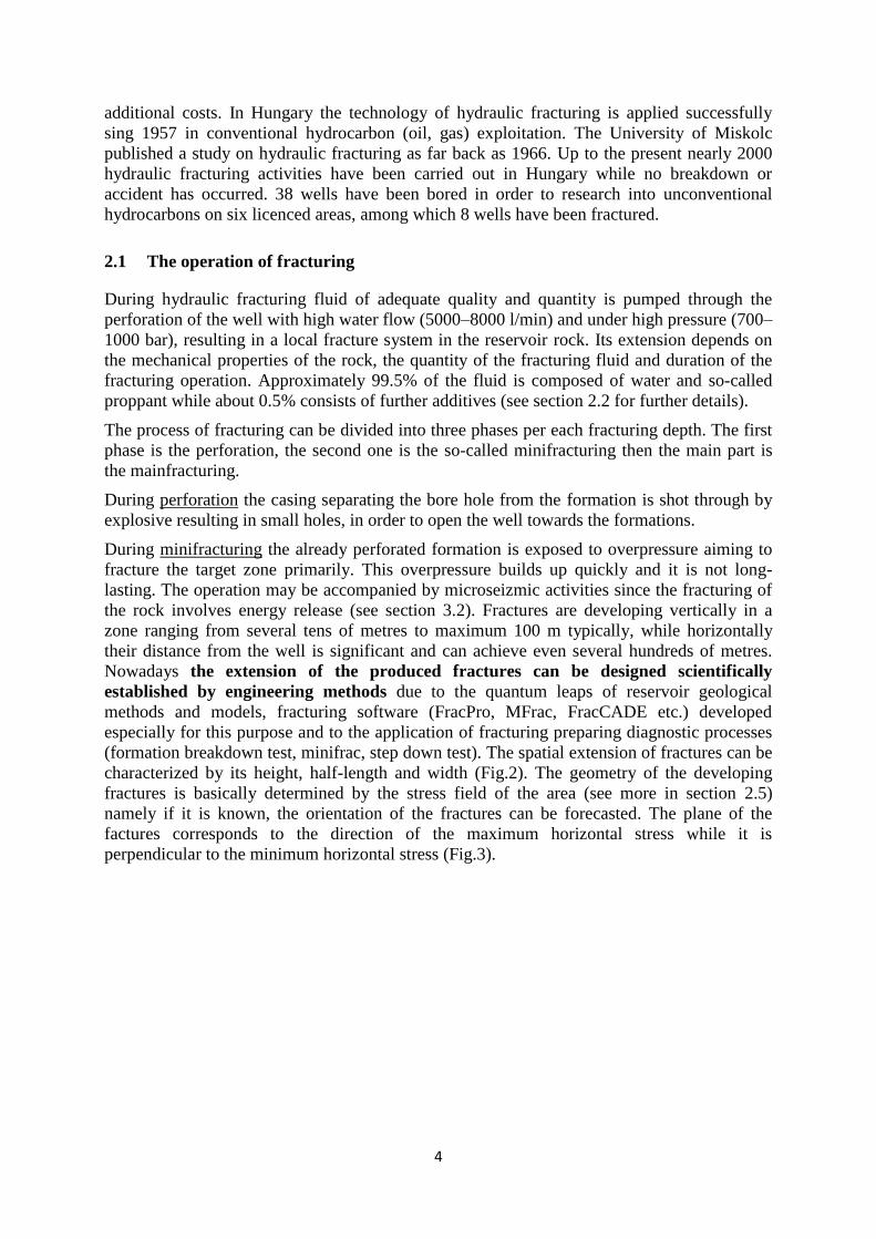
Nowadays the extension of the produced fractures can be designed scientifically
established by engineering methods due to the quantum leaps of reservoir geological
methods and models, fracturing software (FracPro, MFrac, FracCADE etc.) developed
especially for this purpose and to the application of fracturing preparing diagnostic processes
(formation breakdown test, minifrac, step down test). The spatial extension of fractures can be
characterized by its height, half-length and width (Fig.2). The geometry of the developing
fractures is basically determined by the stress field of the area (see more in section 2.5)
namely if it is known, the orientation of the fractures can be forecasted. The plane of the
factures corresponds to the direction of the maximum horizontal stress while it is
perpendicular to the minimum horizontal stress (Fig.3).
Page 7
5
Fig.2. Geometrical characterization of the developed fracture (source: “Introduction to hydraulic
fracturing - training course” MOL)
Fig.3. Connection between the fractures and the stress field (source: “Introduction to hydraulic fracturing
- training course” MOL)
During the mainfracturing the fractures in the already fractured formation are re-opened by
exposing it to overpressure once more then fracturing fluid containing special, good
permeability proppant is pressed into to fractures (see section 2.3 on the types on proppants).
This step is needed to prevent the fractures to shut after the overpressure has ceased. During
this process the density of the slurry is increased by the addition of proppant. This operation
may also be accompanied by microseizmic indications (see section 3.2). After placing the
proppant, the pumped fracturing fluid must be recovered in order that the proppant develop a
stable and high permeability framework. The technical efficiency of fracturing depends to a
great extent on the placing the proppant. As a result of this process the permeability of the
Page 8
6
original rock in the fractured zone is improving ensuring the inflow of hydrocarbons to the
well (Fig.4). Along the developing directed microfractures so-called Darcy type fluid flow
evolves towards the well according to the pressure conditions developing after the fracturing.
Therefore groundwater outside the affected area cannot be polluted since the flow is directed
towards the well, the opposite direction compared to the possibly existing groundwater.
Fig.4. The model of flow before fracturing (radially towards the well) and after that (linearly towards the
facture) (source: “Introduction to hydraulic fracturing - training course” MOL)
The recovered fracturing fluid is expertly cleaned and stored on the surface in multilayer
containers or recycled during another fracturing activity. The reuse of the fracturing fluid is of
specific importance in terms of environmental impacts. The usage of a great amount of
fracturing fluid is a widespread fallacy: 75–90% of the 1000–3000 m3 fluid used on average is
recovered and reused after cleaning. The mass balance of the fracturing fluid pressed into the
formation can be calculated, its dilution and flow can be modelled properly. The migration of
100–500 m3 remaining fluid is considered negligible in a low pressure system conditioned for
fluid exploitation because of the physical characteristics of the production. (Near surface
depressions established by pumping are used to clean polluted groundwater.)
Several Hungarian and international analyses shed light on the fact that the inadequate
forming of the well can imply the real risk of pollution spreading. Its technical solution
and risk is equal to that of conventional hydrocarbon exploitation and usually it is not the
matter in dispute. The adequate well configuration is a fundamental interest of hydrocarbon
and geothermal energy exploiting companies since an improper well can cause the migration
of their product. In order to design casing and cementation, the expected pressure,
temperature, petrophysical and formation parameters can be forecasted accurately based on
the geological model established before the boring and the information gained form the
neighbouring wells. Knowing these parameters the casing with required stability can be
chosen and the cementation be can designed. The casing and production casing, wadding tools
and appliances built in together with them as well as the cement sheath are also used for
preventing the underground water flow and explosion. Hydraulic fracturing is carried out in
existing, bored and configured wells by perforating the multi-secured cement sheath covered
steel tubing and pressing the fracturing fluid into the geological formations. In Hungary no
breakdown or accident has occurred during hydraulic fracturing showing the safety of the
boring circumstances. The different materials and water used for fracturing are transported
through covered and galvanized tubes.
2.2 Composition and quantity of fracturing fluid
The composition of the fracturing fluid is a key concern with regard to hydraulic fracturing.
The fracturing fluid consists of ~94.5% water, ~5% proppant and ~0.5% other additives. This
Page 9
7
topic involves endless debates: people opposing fracturing state that additives include
carcinogenic, allergenic and toxic compounds while oil companies respond with tables (Fig.5)
containing the common application of those materials. This issue can only be solved
satisfyingly if the publication of the exact composition of the fracturing fluid is legally
binding; or if it a business secret of the fracturing company, the company should obtain a
certificate from the relevant environmental/health authority about the classification of the
fracturing fluid [e.g. classification of the Regulation on Registration, Evaluation,
Authorisation and Restriction of Chemicals (REACH Directive), European Chemicals
Agency (ECHA), other domestic waste classification or hazardous material list]. It is also
important to know the exact quantity of components since large amount of fluid is used for
fracturing; so although 0.5% additive seems negligible, in some case it can mean several tons
of materials extraneous to the environment.
Page 10
8
Fig.5. The main components of fracturing fluids (source: API)
The composition of fracturing fluids is presented below based on Jobbik’s (2014) study. The
purposes of the fluid determine its expected properties. The fluid should
develop and properly deepen fractures
transport proppant through the well into the fractures
prevent the proppant from sinking to the bottom of the fracture
minimize the fluid loss towards the formation
be recoverable and cleanable from the well
have as low friction as possible
This means that the fracturing fluid should be viscous and have regulated gel strength
according to the changing temperature and pressure in order to be able to transport proppant;
and it should ensure adequate filtration properties under dynamic well bottom circumstances.
At the same time it should be shearing in order to make its subsequent surface treatment
simple.
During the last 70 years fracturing fluids have been improved significantly. Therefore the
selection of the fluid has become practically a separated profession and nowadays it is
possible to choose a fluid suitable for all the requirements listed above, adjusted to a certain
well.
Subtypes of fracturing fluids are:
water-based gelled fluids or slickwater
Page 11
9
oil-based and synthetic fluids
fluids energized by nitrogen or carbon-dioxide
foamed and emulsive gels
acids
unconventional (viscoelastic) fluids
a combination of the above
The adequately treated and filtered slickwater as a low viscosity fluid is usable for fracturing
in case of shale gas reservoirs because its low viscosity does not limit the transportation of
low concentration proppant. In other cases crosslinked, or time-release or temperature-
dependent delayed crosslink gelled fluids are applied, whose viscosity is higher. For this
reason gelling agents selected based on the pressure, temperature, permeability and the
chemical compatibility with the formation are used. The types of gelled fluids are:
Linear gels
In these fluids the gelling agent is usually guar gum or one of its derivatives such as HPG
(hydroxypropyl guar) or CMG (carboxymethyl guar). Guar is a polymer gained from the seed
of guar plant; and the products made of this material are usually biodegradable. It is non-toxic
and used among others in food industry for ice cream and yogurt production. In general it is
used dissolved in water (or in gas oil – not applied in Hungary) when producing fracturing
fluid.
Crosslinked gels
One of the most important steps in the history of fracturing fluid development was the
discovery of crosslinked gels applied in 1968 for the first time. If crosslinking additive is
added to linear gels, complex and high viscosity fluid is created (Fig.6) whose transporting
capacity is higher than those of simple linear gels.
Crosslinking additive increases the price of the fluid but it improves the efficiency of
fracturing significantly and this way the production index of the well. Crosslinked gels
typically contain metal ion crosslinked guar (Fig.7).
Previously borates, zirconium, titan, chrome or other metal ions were applied typically while
nowadays crosslinked hydroxypropyl guar (HPG) with low environmental impact is used.
Crosslinking agents may endanger human health; however, usually their concentration does
not exceed 1–2 l per 3000–4000 l fluid.
Page 12
10
Fig.6. Crosslinked gel
Fig.7. Crosslinked gel with proppant
Foamed gels
This energized fluid technology uses foam bubbles to transport and place proppant into the
fractures. The most used inert gases are nitrogen and carbon dioxide or a combination of both
in case of binary foams. Carbon dioxide can be added as a fluid while nitrogen in gaseous
state in order to avoid freezing.
The addition of inert gases decreases the fluid demand so the proppant concentration in these
types of fluids may be higher; this way the need for fluid may be reduced even by 75%
compared to conventional linear gels. Foaming agents may contain diethanolamine or
alcohols such as isopropanol or ethanol. As crosslinking agents, these materials may also
Page 13
11
include harmful substances. The recovered fluid is also foamed, the treatment of which
requires severe considerations.
Acids, gelled acids and foamed gelled acids
These acid systems are applied primarily in case of carbonate rocks. Acid dissolves the rock
and after the closing of surfaces dissolved to various degree flowing passages remain creating
“fractures”. Usually the applied acid is hydrogen chloride or a mixture of hydrogen chloride
and acetic acid. In order that the acidic fracturing succeeds several thousand litres of acid
must be pumped far into the formation. However, acids can be used as gelling agents or even
to create perforation.
Additives
In order to make the fracturing more successful, in addition to choose a suitable fracturing
fluid, different additives can be added to the fluid altering its properties according to the
needs.
Breakers
High or low temperature breakers are used to degrade the fracturing fluid viscosity by
breaking long polymer chains in a controlled way when needed, which facilitates fluid
recovery from the formation (makes the fluid able to flow back to the well).
Therefore, breakers aim to maximize the purification and optimize the permeability of
fractures in order to improve the capacity of the well through their mechanism of action.
Breakers can be pumped together with fracturing fluids, or they can be introduced later as
independent fluids for both underground and surface systems. There are different types of
breakers including time-release and temperature-dependent types. Breakers are usually acids,
oxidizers or enzymes. Some breakers may contain harmful components.
Biocides
Guar and other organic polymers serve as excellent habitats for bacteria. It is a serious
problem since bacteria may break down polymers, which reduces the viscosity of the
fracturing fluid and this way the carrying capacity of the fluid, diminishing the efficiency of
fracturing. To prevent this process, biocides are added to the mixing tanks to kill existing
microorganisms and to inhibit bacterial growth.
Leakoff control additives
These additives hinder the leakoff of the fracturing fluid. Previously oil-based fluids used to
be applied for this purpose. Nowadays water-based fluids are used with additives including
bridging materials such as silica flour, talcum or clay. According to the latest developments
surfactants are used, which influence the microemulsion to form a secondary filter.
Friction reducers
During fracturing friction pressure loss is high because of the high pumping rate, flowing
velocity and initial gel strength so high pumping pressure is required. In order to reduce
friction and high technology pressure, friction reducers may be added to water-based
fracturing fluids. These are usually polymer or cation friction reducers.
Clay stabilizer and surfactants
In case of water-sensitive marls and reservoirs containing clay minerals, clay stabilizers
including potassium salts, ammonium chloride and polyamides can be applied in order to
Page 14
12
reduce swelling tendency, prevent formation damage and preserve the initial permeability.
Surfactants modify the surface tension of the fluid supporting its recoverability. They ensure
that the formation retains its original moistening properties.
The amount of fracturing fluid
The amount of fracturing fluid varies depending on the well, however, according to the
international literature (Gandossi 2013) it is 6–12 million l on average (which equals to 3–6
Olympic swimming pool) in case of a well belonging to a significant unconventional
hydrocarbon field. Water is usually recycled. Water demand is typically satisfied by local
water sources.
2.3 Proppants
The purpose of a proppant is to prop a developing fracture, creating a space with enhanced
permeability in order to ensure the permeability after the closing of the fracture. In case of
proppants two questions must be answered:
what kind of, and
how much proppant to use
Considerations determining the type of proppant are the closing pressure of the rock, the
temperature of the reservoir, the grain size needed for the desired permeability, embedment
tendency, the availability of the proppant and last but not least its price.
Proppants can be divided into two groups: naturally occurring sands and artificial ceramic or
bauxite proppants.
Sands are used if the closing pressure of the formation is lower than 400 bars, usually in wells
not exceeding 2500 m; while in deeper wells (having higher closing pressure) artificial
proppants are applied.
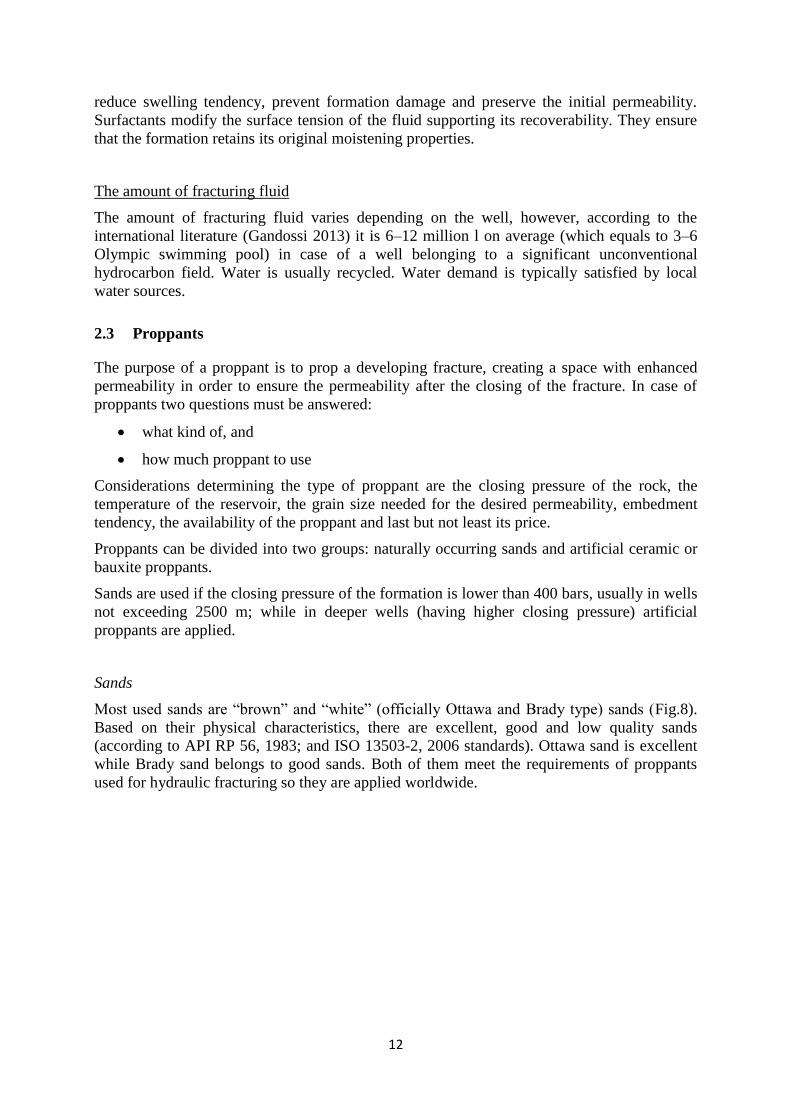
Sands
Most used sands are “brown” and “white” (officially Ottawa and Brady type) sands (Fig.8).
Based on their physical characteristics, there are excellent, good and low quality sands
(according to API RP 56, 1983; and ISO 13503-2, 2006 standards). Ottawa sand is excellent
while Brady sand belongs to good sands. Both of them meet the requirements of proppants
used for hydraulic fracturing so they are applied worldwide.
Page 15
13
Fig.8. “Ottawa” and “Brady” type sands
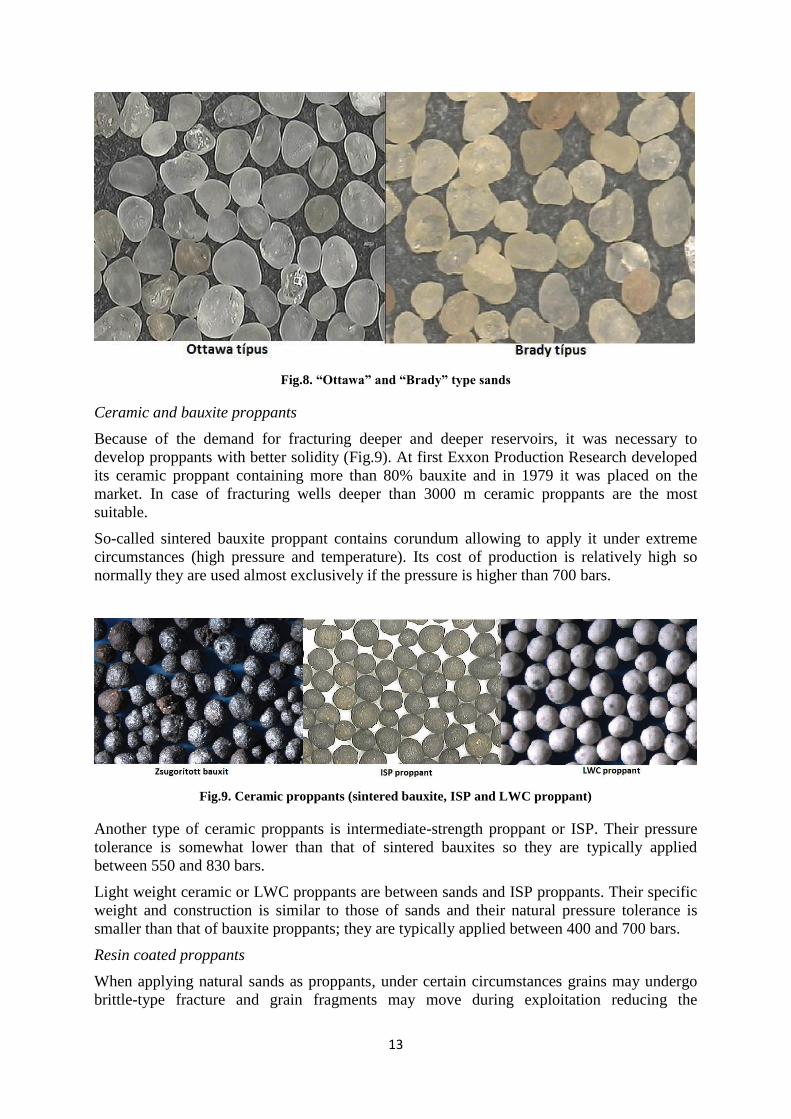
Ceramic and bauxite proppants
Because of the demand for fracturing deeper and deeper reservoirs, it was necessary to
develop proppants with better solidity (Fig.9). At first Exxon Production Research developed
its ceramic proppant containing more than 80% bauxite and in 1979 it was placed on the
market. In case of fracturing wells deeper than 3000 m ceramic proppants are the most
suitable.
So-called sintered bauxite proppant contains corundum allowing to apply it under extreme
circumstances (high pressure and temperature). Its cost of production is relatively high so
normally they are used almost exclusively if the pressure is higher than 700 bars.
Fig.9. Ceramic proppants (sintered bauxite, ISP and LWC proppant)
Another type of ceramic proppants is intermediate-strength proppant or ISP. Their pressure
tolerance is somewhat lower than that of sintered bauxites so they are typically applied
between 550 and 830 bars.
Light weight ceramic or LWC proppants are between sands and ISP proppants. Their specific
weight and construction is similar to those of sands and their natural pressure tolerance is
smaller than that of bauxite proppants; they are typically applied between 400 and 700 bars.
Resin coated proppants
When applying natural sands as proppants, under certain circumstances grains may undergo
brittle-type fracture and grain fragments may move during exploitation reducing the
Page 16
14
permeability of the fracture and the productivity of the well as well as damaging underground
and surface appliances.
In order to prevent this process, resin coat was developed which covers each grains to
improve their solidity. This treatment may be carried out in case of both sand and ceramic
proppants. Resin makes the grains less angular and distributes the load better so they will not
connect only at one point. Resin coats can be divided into two groups: pre-vulcanized and
crosslinking (Fig.10).
Fig.10. Resin coated proppants (pre-vulcanized and crosslinking proppants)
Ultra-lightweight proppants
Proppants are usually chosen based on the closing pressure they must resist. However, the
stronger a proppant is, the bigger is its specific weight and the larger part of the proppant
sinks to the bottom of the fracture. Among conventional materials, sand has the lowest
specific weight (2.65 kg/m3). However, in some cases the proppant need not resist closing
pressure. In these cases ultra-lightweight (ULW) proppants can be applied. Their first
generation, introduced in 2004, has a specific weight of 1.25 kg/m3 which is less than half of
that of sand; and at the same time it is suitable up to 350 bars and 100°C. Later proppants of
2.02, 1.50 and 1.054 specific weight were developed, providing more options (Fig.11).
Fig.11. Ultra-lightweight proppants (specific weight: 1.25, 1.50 and 2.02)
2.4 Fracturing fluids and proppants used in Hungarian practice
It is important to know that there is no universally applicable fracturing recipe and the
technology must be aligned to the given geological settings. The parameterization of
fracturing operations can be carried out only after the well has been bored. The
Page 17
15
properties of target rocks (mineralogical composition, fracturing, porosity, permeability,
formation content etc.) as well as rock mechanical characteristics (compressive and crushing
strength, Young’s modulus, Poisson number, plasticity, brittleness) constitute the bases of the
planning. In order to determine all of these jointly under realistic depth conditions, mini-data
frac is applied.
According to the TXM Ltd. owning an unconventional hydrocarbon mining plot on the Makó
Trench, 300–500 m3 fracturing fluid is needed for each fracturing step while the estimated
annual water demand of a field development is 60 000 m3. The estimated amount of proppant
is 30–100 m3. The expected recovery is 50–80% (reused and eventually neutralized). The
Falcon Company uses both structural viscosity and proppant containing (crosslinked) fluids
and slick water free of proppant for fracturing. The exact composition of fracturing fluid is
not known, but in general it consists of >95% water and 4–5% proppant, thickener, gelling
agent, gel stabilizer, breaker, crosslinking agent, biocide, anti-corrosion surfactant, friction
reducer and clay stabilizer additives (Falcon-TXM 2014). The total concentration of chemical
components amounts to 0.1–0.5% (Table 1).
Additive Main component Concentration
(%) Purpose Common use
Acid hydrochloric acid, organic acids
0.05–0.15 Cleans the neighbourhood of the well
Household detergents
Salt KCl/NaCl 0.01–0.1 Means the salt content of the fluid
Table salt
Scale inhibitor Ethylene glycol ~0.05 Inhibits salt crystallization in steel tubes
De-icer, detergents
Acidity regulator Na/K carbonate ~0.01 Regulates the pH of the fluid Washing powder, soap
Biocide Glutaraldehyde ~0.001 Neutralizes bacteria Disinfectants
Gelling/crosslinking agent
Guar gum ~0.01 Enhances the proppant transport
Foods, cosmetics
Breaker Ammonium persulphate
0.001–0.05 Slows down the degradation of gel
Foods, cosmetics
Oxygen neutralizer Ammonium bisulphate
0.001–0.05 Inhibits the corrosion of steel tubes
Foods, cosmetics
Anti-corrosion N,n dimethylformamide
0.001–0.05 Inhibits the corrosion of steel tubes
Medicines, plastics
Thickener Borate salts 0.001–0.01 Regulates the viscosity of the fluid
Cosmetics, soap
Friction reducer Polyacrylamide 0.01–0.1 Regulates the pumping friction
Water treatment, soil conditioners
Surfactant Isopropanol 0.01–0.05 Reduces the surface friction of the fluid
Hair dyes, glass cleaners
Table 1. Planned composition of fracturing fluid to be used for hydraulic fracturing in Makó Trench
(Falcon-TXM 2014)
In addition TXM claims in its general hydraulic fracturing plan handed in that no chemical
additives harmful to human health or generally to the environment will be used, or their
concentration will not exceed the threshold of harmfulness during the fracturing. It was
declared that only chemical compounds registered in REACH system will be applied and after
the finalization of the fracturing recipe the material safety data sheet (MSDS) and CAS
Registry Number of chemical additives to be used (together with their concentration) will be
placed at the authorities’ disposal.
During its former operations TXM used 30–100 t of 20–60 US mesh (0.25–0.8 mm) calcined
aluminium oxide (corundum) as proppant per each step.
The MOL has entirely put the reports on hydraulic fracturing in Beru-4 well in Derecske
Trench at our disposal. In order to fracture three depth zones 1569 m3 fracturing fluid and 414
t proppant have been used, technically detailed in the aforementioned reports (exact type and
amount of fracturing fluid) (Halliburton 2011, 2012).
Page 18
16
2.5 The role of rock mechanics and stress field in the development of fractures
The development (caused by natural or artificial processes) and geometry (shape and spatial
extent) of fractures in rocks are significantly affected by two main processes: the
composition and mechanical parameters of rocks and the stress situation of the
underground space. Considering clarity, this section deals only with the main aspects of the
geometry of fractures developing in rocks relevant in terms of hydraulic fracturing. For more
details on the fracturing of rocks, processes and parameters developing and influencing them
see Bada et al. 2004.
Due to external forces or deformation stress builds up in a rock body. Rock mechanics deals
with materials systems in equilibrium. The stresses (forces) built up in a solid are illustrated
by three space coordinates. In general the resultant field developing in rocks e.g. as a result of
their own weight and other tectonic stresses is demonstrated by a triaxial ellipsoid, so-called
stress ellipsoid (Fig.12). In solids compressive and shear stresses build up. In the direction of
the principal axes of the stress ellipsoid only compressive stresses act; these are called
principal stresses (σ1≥σ2≥σ3, maximum, intermediate and minimum stress respectively). The
stress field of the rock body is known if the magnitude and spatial orientation of the principal
stresses are known in each points of the rock body. Therefore, the stress state can be
characterized most graphically by the magnitude and spatial orientation of the three axes of
the ellipsoid.
Fig.12. Triaxial stress ellipsoid and principal stress axes (Bada et al. 2004)
The main obstacles of spread of fractures are the natural stress accumulated in the system,
shear solidity, viscosity and plasticity. Basically these factors determine the geometry of the
fracture system, too: the plains of fractures coincide with the direction of maximum horizontal
stress while the perpendicular ones with the minimum horizontal stress (Fig.3). The pressure
derived from the weight of overlying rocks is very significant in depth of several thousand m
and usually it is the maximum stress so the spreading of fractures is mostly vertical. The
development of fractures expanding to the surface from several thousand m depth is
limited by several theoretical obstacles. One of them is that the energy needed for the
development of a vertical fracture system of several km is in proportion to the surface of the
fractures, which is comparable with the weight of the rock mass of such size. In theory as high
pressure can be used as desired, however, in practice it is not possible to maintain a pressure
field above a certain measure (Fisher & Warpinski 2012).
The stress field of the Pannonian Basin is analysed in detail by several studies (e.g. Bada
et al. 2004). According to these the stress field in Pannonian region constituting an integral
part of the Africa-Eurasia collision zone (mobile Europe) is both laterally and vertically
heterogeneous. In this area significant tectonic stresses have been accumulating even
currently, which are released partly through the large-scale bending of lithosphere (vertical
Page 19
17
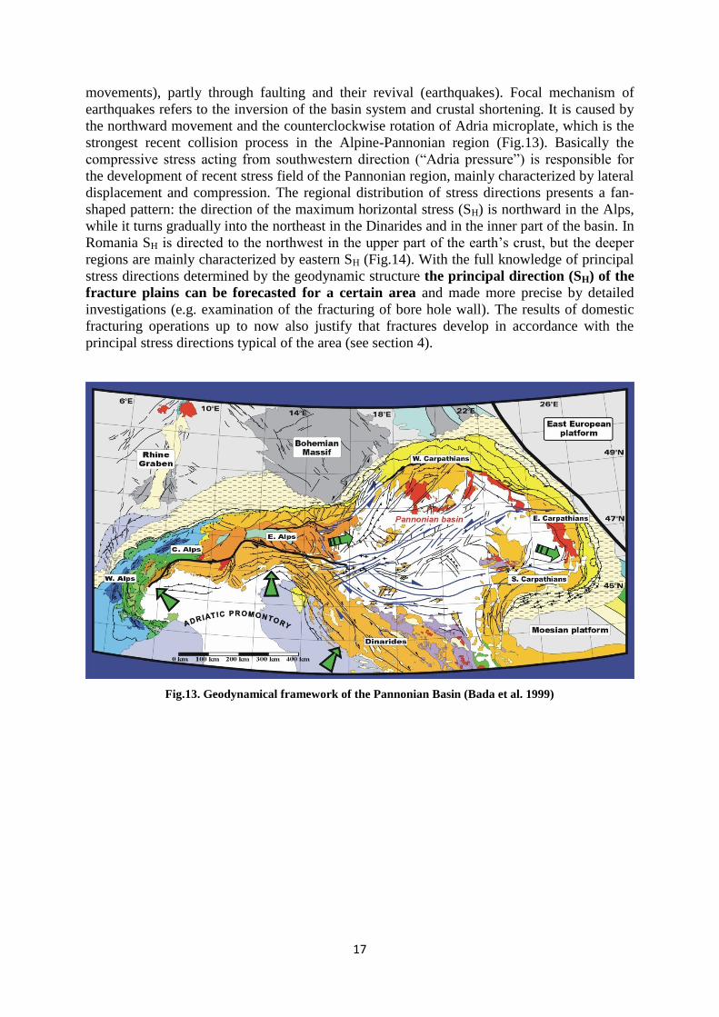
movements), partly through faulting and their revival (earthquakes). Focal mechanism of
earthquakes refers to the inversion of the basin system and crustal shortening. It is caused by
the northward movement and the counterclockwise rotation of Adria microplate, which is the
strongest recent collision process in the Alpine-Pannonian region (Fig.13). Basically the
compressive stress acting from southwestern direction (“Adria pressure”) is responsible for
the development of recent stress field of the Pannonian region, mainly characterized by lateral
displacement and compression. The regional distribution of stress directions presents a fan-
shaped pattern: the direction of the maximum horizontal stress (SH) is northward in the Alps,
while it turns gradually into the northeast in the Dinarides and in the inner part of the basin. In
Romania SH is directed to the northwest in the upper part of the earth’s crust, but the deeper
regions are mainly characterized by eastern SH (Fig.14). With the full knowledge of principal
stress directions determined by the geodynamic structure the principal direction (SH) of the
fracture plains can be forecasted for a certain area and made more precise by detailed
investigations (e.g. examination of the fracturing of bore hole wall). The results of domestic
fracturing operations up to now also justify that fractures develop in accordance with the
principal stress directions typical of the area (see section 4).
Fig.13. Geodynamical framework of the Pannonian Basin (Bada et al. 1999)
Page 20
18
Fig.14. Stress field in Europe and in the Pannonian Basin (Bada et al. 2004)
The investigations carried out in the USA on extension of spatial impact of fracturing can be
analysed statistically; according to these fractures do not exceed 1 km vertically. Davies et al.
2012 also deals with European and African operations and the natural fracture systems, too.
Based on its data artificially stimulated fractures do not go beyond 600 m and only 1% of
them is longer than 350 m. Natural fractures are usually between 2–400 m, however, in
extreme cases they achieve 1 km. The largest vertical fractures may develop if new fractures
join to existing faults (Fig.15).
Fig.15. A: The distribution of the height of natural and artificial fractures;
B: The probability of a fracture not exceeding the certain height (Davies at al. 2012)
The results of hydraulic fracturing carried out in Hungary have been published only about two
hydrocarbon wells (Csólyospálos – CsóK-1 and 4; Zakó&Bencsik, 1996; Gerner et al., 1999).
The stress directions were not, while the minimum horizontal stress was managed to measure,
and based on this the vertical and the maximum horizontal stress could be estimated (Gerner
et al., 1999).
Page 21
19
The spread of hydraulic fracturing faults in made difficult by the vertically changing stress
field. Domestic stress field analyses shed light on the fact that beyond the regional level
vertical direction changes the direction of stress field also changes vertically on local level, in
smaller depths (Bada et al. 2004). These changes are characteristic to overpressure zones
(Csólyospálos, Zsana: Lower Pannonian clay) or strong lithological changes.
Another important factor of the fracture spreading is the inhomogeneous formation: different
petrophysical parameters, local geological structures, different stress situation all increase the
complexity of the fracture system (which is desirable in terms of the process), and at the same
time may result in the dying out of the fractures. Usually more ductile, less fracturable
overlying rock hinders the vertical extension of the fracture. If the fracture achieves a higher
permeability zone, the pressure will decrease because of the leakoff of the fracturing fluid, so
fractures cannot spread further.
2.6 The monitoring of fracturing process
During hydraulic fracturing cost intensive operations are carried out continuously under strict
control and process management. Parameters required for management are measured and
archived in the vicinity of the well continuously allowing immediate intervention if necessary.
During the few hours long fracturing operation the pumping pressure on the site of the
production casing, the backpressure on casing, the pumping rate (l/min), the total quantity and
rheological properties of the pumped fluid and the proppant concentration are registered.
2.7 Geothermal hydraulic fracturing
On the basis of current knowledge, no hydraulic fracturing has been carried out in the frame
of conventional Hungarian geothermal practice and it is not planned for the near future. In
geothermal practice hydraulic fracturing is typically part of the establishment of Enhanced
Geothermal Systems (EGS). The working principle of EGS is that as in case of
unconventional hydrocarbon exploitation, high pressure fluid (water) is pumped into the deep
(deeper that 2500–3000 m), hot (usually warmer than 150°C), typically crystalline, granitic
rock in order to fracture it. After that water is injected from the surface through an injection
well to the artificial fracture system; it warms up flowing through the fracture system of the
deep hot rock acting as a natural heat exchanger and can be recovered through a production
well (or several wells) and utilized for geothermal energy production. According to the initial
concepts (1970s), this operation is suitable even for the fracturing of hard rocks (Hot Dry
Rock) so it was considered to an everywhere applicable, universal technology revolutionizing
the geothermal energy production. However, it has been proved by research and pilot projects
that this method can be applied primarily where the formation has at least some natural
fracture system (though its permeability is low because of the great depth and pressure)
improved by hydraulic fracturing (by widening the existing fissures). This recognition has led
to the concept of Enhanced Geothermal Systems (EGS), on which also nowadays
investigations and pilot projects focus.
EGS technology is in the research and development phase all around the world. In 2013 there
were 31 EGS projects worldwide, covered by the comprehensive analysis of Breede et al.
(2013) (Fig.16). In Europe EGS projects are situated in Germany, France (mainly at the edge
of Rhine Trench) and in Switzerland.
Page 22
20
Fig.16. EGS projects of the World by depth and temperature
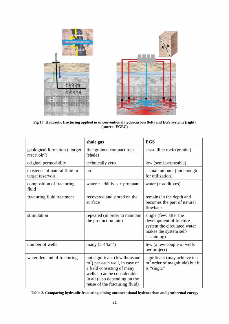
Hydraulic fracturing applied in case of EGS systems differs from the one used while
exploring unconventional hydrocarbons in various aspects summarised in Table 2 and
Fig.17. One of the most significant differences (causing the further ones) is that the fracturing
fluid is recovered in case of shale gas (since otherwise gas molecules could not migrate to the
fractures developed) while in case of EGS the fracturing fluid remains underground and
becomes part of the developing natural flow system. This means that no proppant is needed in
case of EGS since displacement takes place on the existing fractures due to the existing stress
field and the friction decreasing impact of the pumped water, and these fractures do not close
thanks to the uneven surface and the still existing stress field. However, placing proppant to
the developed fractures is crucial in case of shale gas since fractures developed in typically
fine grained rocks with no initial permeability would close quickly after the fracturing fluid
has been recovered. In order that the fracturing fluid is able to carry proppant, chemical
additives (gelling agent, friction reducer) must be added to it to achieve the required quality
(see section 2.2). Additives may be used in case of EGS, too, aiming no to carry proppant
(since no proppant is needed) but to make the chemical composition of the fracturing fluid as
similar to that of the assumed fossil groundwater as possible.
In order to demonstrate the above mentioned differences, recently the word “hydraulic
sliding” is used instead of hydraulic fracturing in the Hungarian geothermal sector, which is
“a technical operation during which no proppant is used and the permeability of fractures
already existing in the rock body is enhanced with a fluid pressure acting on the reservoir not
exceeding a certain value of bed pressure at which new fractures would develop in the rock
body”.
The purpose of this study is not to qualify hydraulic fracturing of shale gas and EGS
compared to each other in any way but to draw attention to the existing technical differences
and the resulting environmental impacts, which should be considered in the light of the
knowledge of the relevant technology.
Page 23
21
Fig.17. Hydraulic fracturing applied in unconventional hydrocarbon (left) and EGS systems (right)
(source: EGEC)
shale gas EGS
geological formation (“target
reservoir”)
fine grained compact rock
(shale)
crystalline rock (granite)
original permeability technically zero low (semi-permeable)
existence of natural fluid in
target reservoir
no a small amount (not enough
for utilization)
composition of fracturing
fluid
water + additives + proppant water (+ additives)
fracturing fluid treatment recovered and stored on the
surface
remains in the depth and
becomes the part of natural
flowback
stimulation repeated (in order to maintain
the production rate)
single (few: after the
development of fracture
system the circulated water
makes the system self-
sustaining)
number of wells many (3-4/km2) few (a few couple of wells
per project)
water demand of fracturing not significant (few thousand
m3) per each well, in case of
a field consisting of many
wells it can be considerable
in all (also depending on the
reuse of the fracturing fluid)
significant (may achieve ten
m3 order of magnitude) but it
is “single”
Table 2. Comparing hydraulic fracturing aiming unconventional hydrocarbon and geothermal energy
Page 24
22
Among other the recent GEISER project (www.geiser-fp7.eu) deals with hydraulic fracturing,
the main objective of which is to develop guidelines for licencing authorities, based on which
the licencing of EGS, the impacts of fracturing, earthquake risk etc. can be treated
satisfactorily.
3 ENVIRONMENTAL IMPACTS OF HYDRAULIC FRACTURING
The detailed analysis of the environmental impacts of hydrocarbon and geothermal energy
exploration and exploitation is included in the relevant sections of vulnerability and loading
capability studies of concessions, entitled “Examination and forecast of impacts and
consequences”. The main purpose of the current section is to summarize theoretically and
introduce briefly the environmental impacts of hydraulic fracturing.
Concrete analysis of certain impacts examined in more detail in the studied pilot areas is
discussed in section 4.
Potential environmental impacts and risk factors of massive hydraulic fracturing compared to
a conventional boring are (Fig.18 and Fig.19):
i. the usage of dangerous chemical substances resulting in the contamination of
groundwater; (applicable chemical substances are supposed to be ruled by the REACH
Directive, however, practically no permission explicitly for fracturing fluid exists in
ECHA database; the registration of these matters is likely to be in progress);
ii. high water demand for fracturing;
iii. natural gas contamination in near surface groundwater in case of inadequately treated
wells
iv. increased land use due to the large number of wells;
v. possibly growing gas/methane emission;
vi. secondary environmental impacts (e.g. storage and cleaning of polluted water, air
pollution stemming from the operation, extraction of radioactive materials etc.);
vii. possibly induced earthquake and additional noise pollution;
viii. the occurrence of natural “toxic elements” dissolved from shales in recovered
fracturing fluid.
However, it is important to draw attention to the fact that some of the impacts summarized in
Fig.18 and Fig.19 are not closely linked to hydraulic fracturing first of all but they do not
differ from other impacts and possible risk occurring during other mining or human
activity. For instance, the storage of recovered fracturing fluid does not differs from the
surface storage of another kind of waste (whose category depends on its composition) in its
nature, risks and environmental impacts. A possibly occurring emergency (such as leaking
and contamination stemming from the damage of the storage pool) is also not a direct
consequence of hydraulic fracturing but a possible risk of all kinds of waste disposal. So the
regulation of such processes does not need to be carried out based on aspects “specific to
fracturing” but current environmental and water protection regulations should be applied to
them.
Page 25
23
Fig.18. Possible environmental impacts of hydraulic fracturing in case of inadequate operation or
emergency (source: EU Impact assessment WD (2014) 21 final, Part 3/4, January 2014)
Hydraulic fracturing such as any other mining activity must be carried out according to the
Technical Operational Plan (TOP). The TOP contains particular requirements for all
environmental media. However, many technical data cannot be precisely and quantitatively
determined during the preparation phase e.g. the detailed description of fracturing technology
for the whole duration of the mining activity (theoretical composition and amount of the
fracturing fluid to be applied, operating pressure to be applied, the quantity and quality of
fluid recovered after the fracturing etc.).
This study deals in detail with two of the environmental impacts listed in Fig.18 and Fig.19,
which are the most often discussed and at the same time the most significant risks specific to
fracturing, namely the effect of hydraulic fracturing on groundwater and the risk of
induced earthquake. The general analysis of how boring activities of fracturing affect the
land use, landscape, cultural heritage, nature conservation on the surface etc. is included in the
vulnerability and loading capacity assessment prepared for each concessions, considering that
those are the same as in case of hydrocarbon exploration and exploitation.
This study does not discuss the role of substances (hydrogen-sulphide, nitrogen, helium, trace
element: mercury, arsenic, lead, radioactive element: radium, thorium, uranium) which are
possible natural components of the shale gas depending on its type and interacting with and
dissolved into the fracturing fluid, may cause environmental risk on the surface. On the one
hand no such petrographic and geochemical data on the domestic shale gas formations is
available, on the other hand geochemical transport and reaction models needed for the
laboratory analysis of the interaction of the fracturing fluid and the shale gas formation are
lacking. However, the chemical monitoring of the recovered fracturing fluid is suitable for the
demonstration of such possible contamination so it is recommended.
Page 26
24
This study also does not dwell on the analysis of another often mentioned environmental risk:
gas/methane emission possibly increasing due to fracturing, the issue of growing greenhouse
gas emission. On the one hand the existence of such emission increase compared to the
conventional hydrocarbon exploitation is a controversial issue up to now; on the other hand
there is no sufficient information to take a national stand on this issue.
Fig.19. Sources and forms of risks emerging during hydraulic fracturing (source: EU Impact assessment
WD (2014) 21 final, Part 3/4, January 2014)
Page 27
25
3.1 The impact of hydraulic fracturing on surface and groundwater
Extensive international literature discusses the impact of hydraulic fracturing on surface and
groundwater and the relevant investigations (e.g. Ewen et al. 2012, Jackson et al. 2013),
which usually deals with
acquisition of the water needed for fracturing and (if it stems from an underground
reservoir) its effect on other (e.g. underlying) aquifers
potential path of gas/pollution spread (along the well, between formations, along
natural faults, along induced faults) and their potential effects on aquifers
(groundwater, drinking water, thermal water)
potential surface contaminations caused by the storage of recovered fracturing fluid
and their potential effect on ecosystem
The environmental pollution risk possibly caused by the fluid applied during hydraulic
fracturing is a potential and one of the most significant risk factors. In spite of the fact that the
perfect well configuration is vital for investors, and boring and fracturing are carried out
under strict technical control, currently there is no universal practice for investigating the
possible effects of deep hydraulic fracturing.
3.1.1 Water acquisition
In terms of the water demand of hydraulic fracturing it is appropriate to separate
unconventional hydrocarbon drillings requiring less water (approximately 500 m3/fracturing,
annually 1500–2000 m3/well) from much more water-intensive geothermal fracturing falling
in all probability under the high volume hydraulic fracturing category of COM(2014) 23 EU
communication (1000 m3/fracturing or injection of at least 10 000 m
3 water in each well).
These values are, however, only indicative. It should be taken into account that the water
demand of geothermal hydraulic fracturing depends heavily not only on the physical
parameters of the reservoir rock but also on the location of wells, their district-like or bush-
like distribution. It should be considered as well that although the water demand of
geothermal hydraulic fracturing is generally more significant but only a few couples of
production and injection wells are expected to be applied in a certain area while drilling and
fracturing during the development of an unconventional hydrocarbon field take several years
so individual water needs cumulate (however, the recycling of fracturing fluid should be taken
into account, too).
Recently in Hungary water body based water management is carried out (according to the
requirements of Water Framework Directive – WFD). In accordance with the WFD the state
of the body of water determines whether the water demand of fracturing can be met locally.
At present the first version of River Basin Management Plan (RBMP) is in force so it is
necessary to take into account the quantitative status of (typically near surface, porous) bodies
of waters situated under the exploration area.
When planning for the satisfaction of water demand, the following must be considered:
a) the required quantity and quality of water,
b) water conditions of the relevant area,
c) water reserve covered by water licence,
d) the amount of water to be left in the river bed, and
e) the degree of water stress tolerance.
Page 28
26
3.1.2 Sources of pollution and their potential spread
In case of groundwater pollutant may stem from natural or artificial (anthropogenic) sources.
Pollutant of natural origin may get into the groundwater (primarily into the shallow
groundwater) due to chemical and physical processes from the atmosphere, biosphere and
lithosphere. During fracturing theoretical sources of natural pollution may be components
possibly being dissolved as a result of the interaction between the shale gas reservoir rock
and the fracturing fluid (methane, carbon-dioxide, hydrogen sulphide, mercury, arsenic, lead,
radioactive components of natural origin: radium, thorium, uranium), dissolved in the
fracturing fluid may involve potential environmental risk on the surface. As mentioned at the
beginning of section 3, data are not available – primarily due to the lack of geochemical
analyses – for more detailed evaluation, and the objective consideration of this issue is
supported by only little international experience. However, according to the conventional
hydrocarbon mining practice the risk of these pollutions is diminished by the technological
configuration of surface systems to a level accepted so far.
Theoretically pollution sources deriving from human activity (anthropogenic sources) may be:
solid waste disposals
sewage lagoons
agriculture
oil leak or flow
deeply buried toxic waste
mining, underground work
A special case of anthropogenic pollution is when the quality of groundwater is modified by
connecting different aquifers or by various underground operations e.g. well configuration
and formation stimulation.
Potential types of pollution are:
Gases
Primary potential polluting impact of unconventional gas exploitation is the methane
containing gas migration itself. The number of gas and water-containing pores are roughly
equal in shales; however, the solubility of methane heavily depends on temperature, pressure
and the total solute content of the fluid.
Natural methane may be of biogenic or thermogenic origin, besides in terms of technology
there are wet and dry gases, propane-butane gas mixtures, C1-Cn gases and gases resulting
from bio-geochemical processes (O2, CO2, CH4, N2, H2, H2S). In addition gases of
atmospheric origin (O2, N2, Ar) and inert gases characterized by low chemical reactivity (such
as He, Ne, Ar, Kr, Xe, and Rn) occur, too.
Induced migration processes can be detected if the results of gas analyses measured in the
vicinity of fracturing are compared to gas analyses carried out after the fracturing.
Fluids
Recovered water must be considered as potential source of pollution, whose chemical
composition is fundamentally influenced by the composition of drilling mud, fracturing fluid
and (syngenetic) pore water.
Page 29
27
The chemical composition and applied quantity of the fracturing fluid is specific to location
and varies depending on the outcomes of on-site examinations.
Potential general composition of the fracturing fluid is summarized in Table 3 (see also
Fig.5).
Component types and their application
function
Chemical composition
Carrier, transfer medium Water, N2, CO2, LPG, foams and emulsions
Proppant – propping the fracture during the
loss of pressure subsequent to fracturing
Sand, resin coated sand, sintered bauxite,
aluminium, ceramics and silicon carbide
Acidizing, cleaning after fracturing HCl and other acids
Additives to adjust the viscosity of the fluid
and gelling agents to keep proppant in
suspension
Guar gum, cellulose-based derivatives,
gelling and crosslinking agents (borate
compounds and metal complexes)
Viscosity reducers after the fracturing fluid
reached the target zone
Ammonium persulphate, sodium persulphate
Stabilizers, biocides, friction reducers Latex polymers or co-polymers of
acrylamides and acidic corrosion inhibitors
such as alcohol
Acidic corrosion and scale inhibitors isopropanol, methanol, formic acid,
acetaldehyde
Friction reducer, lubricant, where proppant
enters the fractures deeply
Surfactants, polyacrylamides, ethylene glycol
Biocides to hinder the decomposition of
sulphate
Aldehydes, amides
Surfactants to improve the relative gas
permeability
Isopropanol
Clay stabilizer to prevent flocculation KCl
Other glycols, amines, defoamers
Table 3. Theoretical composition of fracturing fluid [Source: US EPA 2011; Schlumberger (www.slb.com),
and OpenFrac.com via Jackson et al (2013)]
As the table above shows exceptionally wide range of substances are applied, significantly
differing from components used for water source protection monitoring. Therefore, permitting
authority requires rightly disclosing the chemical composition of the fracturing fluid
before starting the fracturing work, or proving that it not hazardous.
Pollution may potentially reach shallow aquifers (drinking water)
1) along the bore hole (casing or cement sheath)
2) from the surface (stored fracturing fluid)
3) along natural faults
4) along induced faults.
Page 30
28
In terms of aquifers (water sources) in proximity to conventional hydrocarbon reservoirs the
produced hydrocarbon itself is considered hazardous toxic substance. The hydrocarbon
occurrence in water source means that hydrocarbon may get into the product of the well or the
annular space around the casing; so hydrocarbons stored in formations drilled though or
situated in reservoirs hydrogeologically connected to them are potential sources of pollution.
In case of unconventional hydrocarbons such phenomenon does not occur since there is no
water source in depth where unconventional hydrocarbons are situated (typically under 3500
m) and in low permeability rocks.
In general a dispersion environs occurring above hydrocarbon deposits contains sulphides too.
The arsenic contamination above the deposits may be caused by defective cement sheath since
aquifers and arsenic-containing shales short-circuit. Surface pollutants may also get into the
drinking water reservoir rocks through a well bearing inadequate cement sheath so they are
considered increased hazard. Exhausted or in terms of industrial use unproductive formations
may also contain as much gas that it must be taken into account during the configuration of
future water wells. Surface contaminations may relate to agriculture, mining activity,
communal sewage, traffic and other soil-polluting activities. However, all these are the
impacts of conventional hydrocarbon production and do not imply additional risk in terms of
hydraulic fracturing.
The analysis of hydraulic fracturing applied in order to exploit unconventional hydrocarbons
is continuously developing. The tracking of the fracturing fluid may provide an opportunity to
examine the impacts of fracturing (Warner et al. 2014). The application of boron (δ11B) and
lithium (δ7Li) isotope determination method developed by the Geological Survey of France
and the Duke University (USA) may be a potential tracking solution beside the traditional
parameters (electrical conductivity or total solutes, methane, chloride, iodide, bromide,
radionuclides). The assessment of initial conditions (water geochemical conditions before
fracturing) is important and practically includes the identification of beyond the main
component and trace element concentrations the radionuclide and dissolved gas content of the
water stored in aquifers located not further than a few kilometres from the planned fracturing
and in various hydraulic zones, as well as the δ 13C and δ D content of methane. Monitoring
the neighbourhood of the well after fracturing is of specific importance.
According to the fifth appendix of the water source protection law entitled “Governmental
Decree No. 123/1997 (VII.18.) on the protection of water sources, prospective water sources
as well as water supply facilities” it may be allowed to drill a new well inside the outer and
hydrogeological A and B protection zones depending on the result of environmental impact
assessment, environmental audit or another assessment with equivalent content. In line with
the above, more rigorous regulation is not necessary in case of a borehole not affecting, only
crossing the aquifer, since if the cement sheath gets damaged which is very unlikely, the fluid
flow from the well may last for a very short time.
3.1.3 Potential environmental risks on the surface caused by the storage of the recovered
fracturing fluid
As mentioned at the beginning of section 3, this study does not deal in detail with the possible
polluting effects of the fracturing fluid stored on the surface so only the most important
aspects are summarized here. The recovered water must be stored in a closed (specially
engineered) reservoir and its emplacement after the disposal must be carried out according to
the legal requirements. The protection of surface waters and wetlands is of specific
significance.
Page 31
29
When making a plan for the emplacement of used water or sewage, the following must be
determined according to the requirements of regulations on water protection:
a) the expected quantity and quality of used water or sewage;
b) the load capacity of the reservoir;
c) the way of introducing the water into the reservoir;
d) the sewage treatment method; and
e) solutions with the lowest environmental load based on technical and economical
calculations.
3.1.4 The role of hydrogeological monitoring
The protection of underground drinking water sources and thermal water bodies as well as the
sustainable water management is the responsibility of the society as a whole and interests of
the economy at large. Since in Hungary water body based water management is carried out
according to the requirements of Water Framework Directive (WFD), which includes
monitoring as an integral part, these should be considered within the monitoring requirements.
In Hungary no diagnostic examination about the possible negative impacts of hydraulic
fracturing has been carried out from a hydrogeological point of view up to now. According to
the united stand of the authors, uncared boreholes with ruined cement sheath imply the
highest safety risk of hydraulic fracturing. Therefore, the assessment of boreholes and
wells located in a certain area (where justified, cement bond log – CBL, even repeatedly) and
their suitability for sampling are important elements of hydrogeological monitoring.
It is reasonable to monitor the sallow groundwater from a hydrogeological point of view in
case of hydrocarbon deposits of large surface extent, especially in the vicinity of wetlands
where significant construction works are carried out or large amount of solid or liquid
pollutants are stored for a long time. The wells of Hungarian sallow groundwater monitoring
network can be used for this reason; in some cases new ones need to be drilled (considering
the specific costs of drilling a sallow groundwater well) taking into account flow patterns.
Considering the high specific costs of drilling a deep (> 1500 m) well, drilling further wells
for monitoring cannot be a general solution, only in certain cases. The proximity of the
nearest aquifer, the permeability of the formations between the aquifer and the formations to
be fractured, and the risk that a possibly renewing fault system develops inside these
formations must be considered.
During safety assessment and the development of monitoring system the possible flow paths
need to be taken into account. The flow rate is extremely low in formations whose vertical
hydraulic conductivity is at most 10-7
–10-8
m/s, so hydraulic fracturing is secured from a
geological point of view, however, improperly configured wells or whose cement sheath is
damaged can serve as a direct connection. It is reasonable to carry out object-oriented
diagnostics in the exploration area, to record the water chemistry before fracturing and to
monitor the water chemistry specific for fracturing fluid after fracturing.
3.1.5 Other hydrogeological aspects
Hydraulic fracturing in Hungary has been carried out at significant depths under the drinking
and thermal water reservoirs up to the present. The lower boundary of a water body is not
clearly determined by the water management plan and cannot be considered exact. As a
general rule, the 30 °C isotherm is the lower boundary of deep cold (porous, karstic) water
bodies. Under this boundary porous and karstic thermal bodies of water are situated, however,
Page 32
30
these do not cover the whole country (e.g. there is no designated thermal body of water under
cold karstic water bodies, and fractured thermal water bodies are neither bordered since they
are slightly relevant).
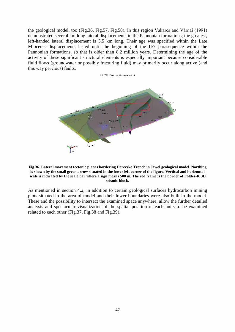
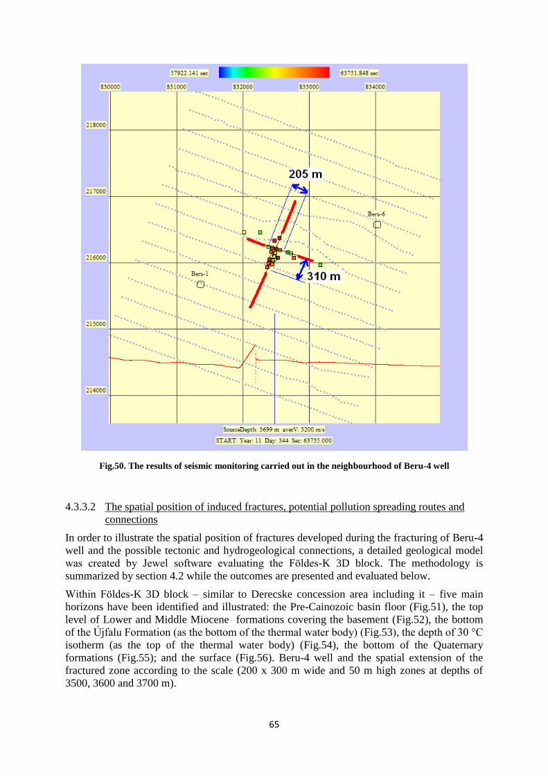
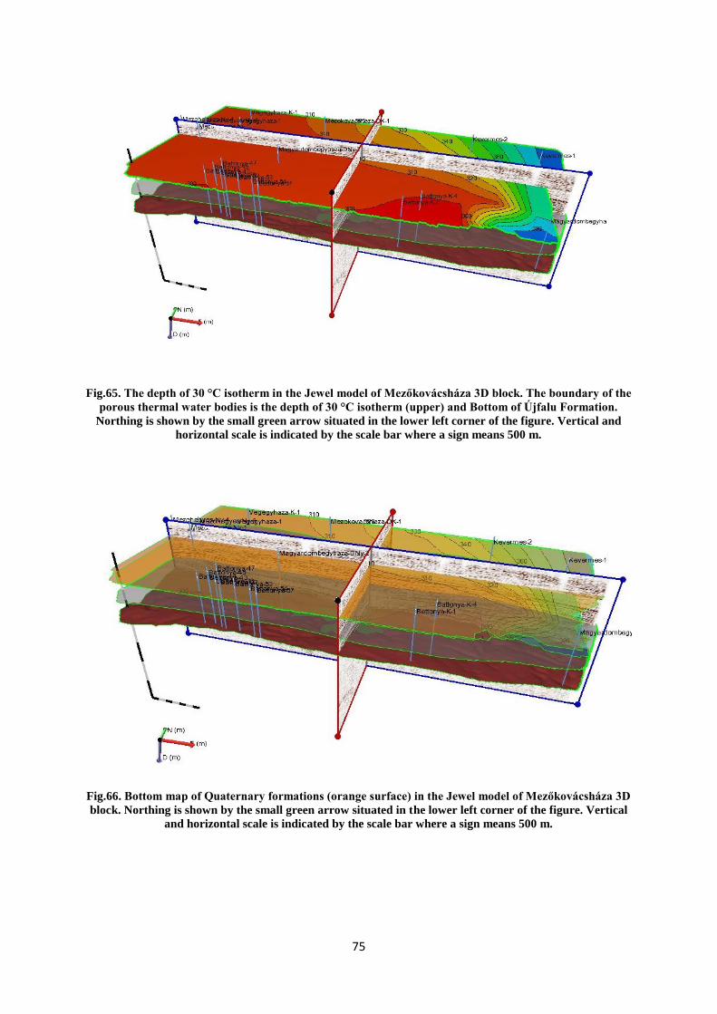
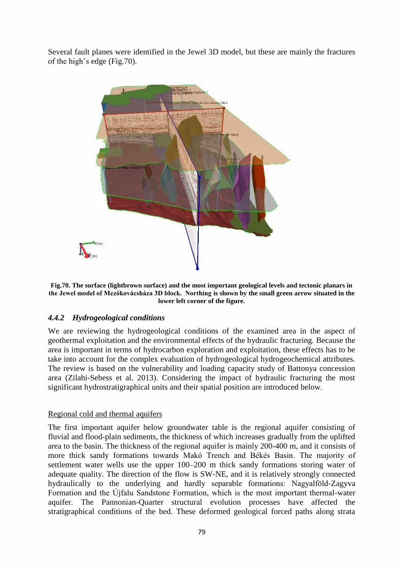
In order to regulate the fracturing process efficiently, it is necessary to border each body of
water vertically (taking into account geological and hydrogeological considerations), and
keeping a concrete distance can be prescribed only in this case e.g. 300 m (porous) or
500 m (karstic). In the other hand, the purpose of obligatorily prescribed distance accords
with the function of safety zone or protective pillar applied in mining. According to the
mining law (Act No. XLVIII. 1993 on Mining): “The settlement, underground and surface
installation, water resources, river and still water, historic real estate, and protected natural
territory shall be protected from the effects of the activity carried out with respect to the
establishment referred to in paragraph (1), with the designation of protective pillar (boundary
pillar, protective pillar) in case of necessity. The protective pillar shall not be jeopardized
during the activities. The Mining Authority may authorise the scaling or weakening of the
protective pillar by hearing of the stakeholders, if its purpose has ceased or the safety and
protection requirements may be met otherwise.”
During the first phase of permitting procedure it is practical to designate a multicomponent
planned impacts protective zone (from a structure change /e.g. expected half-length of
fractures/, hydrogeological, geothermal, reservoir or pressure point of view), which needs to
be specified or modified based on the investigations and drilling operations, also
accompanying the modification of TOP. The geothermal protective zone is elaborated
precisely, the approach of which can be also applied in hydraulic fracturing process.
3.2 Earthquake risk (induced seismicity)
During hydraulic fracturing the breaking and fracturing of rocks are triggered intentionally by
injecting fluid under great pressure so the process causes seismicity by its nature. There are
two types of induced seismicity occurring during fracturing:
(1) Microquakes are triggered by the developing new faults/fractures and reactivating
microfractures in the reservoir (Fig.20). This process routinely accompanies the
technology; and in order to optimize the process it is previously modelled and during
fracturing attempted to be monitored. Passive seismic is the most efficient method for
monitoring. Emissions of very low energy – microquakes can be measured only by
sensitive instruments possibly set underground if noise sources are eliminated. Based
on several 10 000 examined and detected events their magnitudes exceed one only
exceptionally and their spatial extent is limited to the some 100 m neighbourhood of
the fracturing (Ellsworth 2013, Fisher & Warpinski 2011).
Page 33
31
Fig.20. Microquakes in Jonah field (Wyoming, USA). The blue dots indicate the quakes triggered by the
spread of fractures during the fracturing of the well East 3, while yellow and green dots outline the
microquakes related to the renewal of a small fault (Davies et al. 2013)
(2) Much rare but several magnitudes larger earthquakes are triggered by the stress
affecting existing faults, whose magnitudes (between 2.1–3.8, Davies et al. 2013) are,
however, still on the verge on human perception, therefore they are not expected to
damage human lives, buildings, infrastructure and nature (Fig.21).
Fig.21. The relation of earthquakes confirmed to be triggered by hydraulic fracturing (broken red line) to
natural earthquakes (based on data of Davies et al. 2013 in the figure of www.seismology.hu)
In case of hydraulic fracturing fluid occurring in fault zones acting as “lubricant” may be a
source of stress, causing the fault to weaken and reactivate due to the increased fluid pressure.
Problem may rise if the fracture network and the known fault zones become connected and
the fluid itself or the surplus pressure caused by the fluid gets to the fault zone. The fracturing
fluid – or its surplus pressure – may get into the fault zone in several ways: (1) directly from
the borehole, (2) through new fractures, (3) through existing fracture, (4) through formations
of greater permeability.
Rétegrepesztés
Page 34
32
Earthquakes with magnitudes higher than those of generated by hydraulic fracturing (max.
5.6; Oklahoma - Ellsworth, 2013) occurred in the neighbourhood of North-American water
injection wells, where very large amount of fluid was injected and/or the operation took place
in the vicinity of significant, known fault zones. On the one hand it implies that the quantity
of the fluid increases the risk, on the other hand an American study (Elst et al. 2013)
highlighted that these areas are basically more “sensitive” to seismic events, assuming faults
closed to the critical stress. Therefore, significant earthquakes can occur where the natural
state of the system is nearly critical (close to the shear strength limit).
Considering all these, independent international studies (e.g. The Royal Society 2012, Ewen
et al. 2012, Davies et al. 2013, National Research Council, 2013) pointed out that hydraulic
fracturing is accompanied by low seismic risk. With reference to earthquakes (induced or
natural ones) it is important to note that only the energy accumulated in a certain space can be
released during the activity of faults. It follows that it is true theoretically also that the
magnitudes of earthquakes possibly induced by fracturing will not exceed those of
shallow earthquakes occurring in the same space. In addition it cannot be excluded that –
in regions where natural earthquakes are frequent – the induced seismic events assist the
development of earthquakes. However, this can be avoided by the detailed investigation of
geological circumstances, the cognition of the stress field, the avoidance of large faults
reaching the surface, fault zones and tectonically active regions, the maintenance of fluid
balance (injected and recovered amounts), careful planning and monitoring.
3.2.1 Induced seismicity – general review
Rocks deform due to stress and if stress achieves a critical level depending on the composition
of the rock, the pressure of its environment and the temperature, brittle fracture occurs and
blocks of rocks move compared to each other along the newly developed fracture plane
(fault). As a consequence, energy accumulated over a long period of time is released in
seconds mainly as flexible waves i.e. an earthquake is triggered.
Induced seismicity (or induced earthquake) is an earthquake triggered by human activity
along newly developed fractures or existing faults in the earth crust. It can be caused by the
removal of rock or fluid during any kind of mining activity or on the contrary the injection of
large amount of fluid into the earth crust. Induced earthquakes may occur where tectonic
stresses can accumulate. A fault moves if normal stress decreases to such a degree that shear
stress exceeds the shear strength of the fault plane (Mohr–Coulomb failure criterion). This can
be achieved by the growth of shear stress e.g. due to lateral displacements, or by the decrease
of normal stress caused by erosion (all these are slow and natural processes of geohistorical
dimension), or the removal of upperlying formations or pore fluid, or the increase of fluid
pressure (artificial effects) – playing an important role in case of hydraulic fracturing. The
development of brittle fracture is moderated if the rocks are plastic or viscous, or porous,
multiphase and sedimentary type (e.g. clays, silts, sandstones etc.), characterised by lower
strength, preventing energy absorbance and fault development. Growing temperature acts also
against the development of brittle fractures, increasing the viscous nature of the rock and this
way its energy absorbability. This effect is significant at great depths of the Pannonian Basin
because of the geothermal gradient over the world average.
Based on the above, there are some general findings on the magnitude of induced seismicity:
- It depends on the petrophysical parameters of the fractured rock (compressibility
factor, shear modulus, ductility, porosity, temperature): for example, the harder a
brittle rock crashes, the more energy is accumulated and the larger the perceived
microquakes are, but the more ductile it is or if it is young (Neogene) sedimentary,
Page 35
33
porous, multiphase, the more the accumulated stress is absorbed and the less
seismically active and hazardous the region is.
- It depends on the size of existing and renewable faults: the larger its surface is, the
greater the induced seismicity will be.
- It depends on the tectonic and stress state of existing and renewable faults: the more
stress is stored, the greater the induced seismicity will be, but the earthquake to be
triggered will not exceed the energy accumulated in that certain space.
- It depends on the pressure conditions of fracturing: injection of great quantity and
intensity increases the pressure while it is decreased by fast and extensive backflow.
- Based on the above and the cases recorded so far, the magnitude of realistically
estimated induced seismicity is much lower than that of constantly acting and recorded
natural seismic activity.
Fig.22. Induced earthquakes with magnitude higher than 1 plotted against the human operation (Davies et
al. 2013). The study covering 198 cases since 1929 shows that the magnitude of seismic events induced by
fracturing (black) is much lower than those of seismic events caused by mining activity, petroleum and
natural gas exploitation or hydrocarbon production with water injection
3.2.2 Seismic activity in case of unconventional hydrocarbon exploitation
Based on the data of international literature, induced seismicity observed in case of
hydraulic fracturing – whose estimated realistic maximum magnitude is approximately
3 on world average (The Royal Society 2012) – is low compared to other mining activities
(Fig.22). Since these earthquakes are triggered at great depth (2–6000 m), they are hardly
perceptible by humans and they are neither expected to damage buildings even slightly.
However, the question arises as to whether the fracturing causes damages to the well (casing,
cement sheath), increasing the pollution risk. According to the generally accepted view, since
seismicity affects wells at the depth of perforation, it does not imply extra risk. However, the
technical state of the well is worth examining later repeatedly if a seismic activity greater than
expected is detected by seismic monitoring.
Up to the present 79 events with magnitudes higher than one have been recorded from three
locations (Eola oil and gas field, Oklahoma, USA; Preese Hall, Lancashire, United Kingdom;
Page 36
34
and Horn river basin, Brit Columbia, Canada) according to published data. The magnitude of
greatest recorded seismic event triggered by fracturing was 3.8 (Davies et al. 2013). In 2011
earthquakes with magnitudes of 2.3 and 1.5 were detected in Lancashire by the British
seismic observation network. The subsequent investigation established that the fracturing
fluid reached a tectonically active fault, which has not been recognised earlier, decreasing the
effective stress to a degree that the fault slid and the stress accumulated so far was released
(Green et al. 2012). Based on the causes, the bed planes of fractured shale is likely to be so
weak that they slid during fracturing allowing the fluid to reach the relatively distant fault.
Generally the seismicity of Hungary and the Carpathian Basin is considered medium. Based
on the observations so far annually four or five earthquakes with magnitudes of 2.5–3.5 can
be expected, which are perceptible but do not cause damage. Earthquakes causing moderate
damage occur every 15–20 years, while stronger, more damaging earthquakes with
magnitudes of 5.5–6 are triggered every 40–50 years. The distributing of quakes is not
homogenous; the surrounding orogenic areas, which are the most active parts of the region in
terms of seismicity, significantly differ from the inner part of the basin (Fig.23). Areas
affected by hydraulic fracturing (primarily the Great and Little Hungarian Plain) are the less
active parts of Hungary.
The upper, on average 3 km (0–6 km) thick young (Neogene) sedimentary part of the
Pannonian Basin is made up of law strength, porous, clayey rocks, which on the one hand
can significantly diminish the energy of earthquakes and on the other hand are not
favourable in terms of seismic activity. Due to the considerable amount of young sediments as
well as the high geothermal gradient improving the plasticity and viscosity of deep rocks the
seismic activity in Hungary differs (positively) from the world average. In other words,
because of the above mentioned factors the seismic activity in the Pannonian Basin is lower
than in several other basins of the world.
Page 37
35
Fig.23. The distribution of earthquakes occurred in the Carpathian Basin and its neighbourhood between
456 and 2006. The size of symbols is proportional to the Richter magnitude of earthquakes
(www.seismology.hu)
If unfortunately energy is released from a tectonic zone during fracturing, the quantity of the
released energy can be estimated. Seismic data constituting the base of Fig.24 has been
processed based on Tóth et al. (2013). The statistical analysis clearly points out that flexible
energy accumulated in the part of the Pannonian Basin affected by hydraulic fracturing can
most likely generate earthquakes with magnitudes of 1–2.5 under natural conditions. Induced
seismicity releases a part of the accumulated stress so in case of the most disadvantageous
technical and tectonic circumstances earthquakes with a magnitude of ~ 1.8 can be
triggered in Hungary most likely. However, the dissipation capability of young sedimentary
formations able to absorb energy should also be considered, thanks to which such an activity
practically cannot be perceived by humans on the surface.
Page 38
36
Fig.24. The distribution of magnitudes of earthquakes in the above 10 km of Pannonian Basin based on
literary hypocentre and magnitude data determined so far
To sum up, international data suggest that the probability of induced seismicity during
unconventional hydrocarbon mining is low (Fig.21). If seismic activity occurs during
fracturing because of unfortunate tectonic and technological conditions, considering the
domestic geological and geophysical circumstances an earthquake with a magnitude of ~ 1.8
can most likely be triggered in the worst case scenario, the majority of which energy will be
absorbed by the thick and young sediment formations able to dissipate energy. Therefore, the
risk of seismicity (release, damaging effect on the surface) induced by fracturing endangering
built environment is not at all higher than in case of any accepted hydrocarbon exploitation
technology. The several decade long history of domestic fracturing compared to the seismic
activity shows that in Hungary seismicity or tendencies caused by this technology cannot be
recognized in data.
3.2.3 Seismic activity in case of geothermal systems
Somewhat higher induced seismicity (max. 4.6, Geysers, California, USA) has been observed
in case of geothermal (EGS) systems. This is mainly caused by the fact that economic
geothermal resources are situated in tectonically active zones. In these cases the seismicity in
mostly caused by the local stress state, however, it is directly triggered by the increased pore
pressure developing on faults. However, as a prerequisite pore pressure should be in
connection with adequately oriented faults. An additional factor is the shrinkage of the hot
rock when coming into contact with the colder fluid, reducing friction on the surface of the
fault and this way promoting movement along the fault. In certain cases this process leads to
the development of new fractures. Extensive water extraction and injection may cause change
in the volume of the reservoir, disturbing the local stress field and resulting in displacements
on critical faults (Majer et al. 2007). When the injected fluid comes into contact with the
source rock, geochemical processes take place resulting in fault movements, which can also
be traced back to the changes of friction in fault planes. The best documented (and oldest)
example of increased seismicity is the Geysers Field in the USA: the growth in the intensity
of microseismic activity of the region characterized by lateral displacement tectonics was
primarily considered the result of water injection and steam exploitation.
The EGS project in Basel, Switzerland was interrupted in 2009 due to the strong public
protest because of induced earthquakes with magnitude of 3, however, in 2013 in St Gallen
Page 39
37
after a 5.5 week long stop following a 3.6 magnitude earthquake, the city council gave
permission for the continuation of the project (Breede et al. 2013).
Several publications address the topic that increased natural seismic activity occurs in the case
of some geothermal reservoirs (but not generally). High pressure water-vapour systems may
cause small earthquakes and soil disturbance because of their mobile nature (Geos 1987).
Among anthropogenic impacts, injection is one of the most common causes of induced
seismicity. This is verified by several cases where even a magnitude 5 earthquake has been
observed related to water injection (Rocky Mountain Arsenal in Colorado, USA, Dallas-
Forth Worth Airport, Texas, USA). It is caused by the long-time stress as well as the
extremely large amount of injected water compared to hydraulic fracturing, allowing the
development of greater fluid pressure (Frochlich et al. 2011).
In summary, the magnitude, quantity and way of induced seismicity is primarily determined
by the quantity and ratio of the injected fluid, the orientation of pore pressure growth
caused by the fluid compared to the local stress field, the hydrological properties of the
reservoir, petrophysical parameters, the extension of local fault systems, the size of faults and
last but not least the stress field and natural seismic activity.
In order to reduce induced seismic risk it is necessary
(1) to gain detailed geological knowledge, especially to map faults by seismic
measurements, build a validated geological model, identify the stress field and
document natural seismicity as precisely as possible;
(2) to carry out tests prior to the mainfracturing (e.g. MiniFrac);
(3) to monitor seismicity real-time allowing the immediate feedback of the outcomes and
if necessary the modification or stopping of the process (so-called traffic light system)
(Fig.25)
Fig.25. An example for the traffic light system developed for Basel EGS project. The feedback system can
be developed considering local geological circumstances and seismic activity as well as the time
consumption of geological processes
3.2.4 The role of seismic monitoring
The monitoring of fracture spread is of fundamental importance in terms of both process
optimization (to achieve that fracturing stays inside the target formation and to determine
suitable well distance) and risk mitigation. When planning monitoring, the first basic step is to
record the initial state: to study the petrophysical parameters, the stress field and the natural
fracturing (orientation, length, height, the width of fractures and permeability). These data are
also necessary for planning the fracturing process, the key of which is the forecast of fracture
spread by modelling. Tests prior to fracturing, seismic measurements and microseismic
monitoring are required for gaining model data.
Page 40
38
Before, during and after fracturing several methods can provide further information. A group
of these is adding chemical or radioactive tracers to the fracturing fluid or proppant, from the
dilution and return period of which the nature of fracturing can be concluded (Bennett et al
2006). Tiltmeter placed on the surface or in the borehole is a passive observation method
aiming to measure the deformations caused by hydraulic fracturing.
Another significant, more frequently and effectively applied group is the group of passive
seismic methods. The method is based on the energy released during fracturing when
fractures open, generating microquakes (microemissions), while waves are analysed on the
surface or in the borehole. It is also called microseismics since the magnitude of detected
seismic activity is extremely low. Compared to seismics, the main difference is that in that
case the exact location and time of the source is known (intentional energy input, for example,
explosion for imaging) while in case of passive seismics these are unknown. The goal is to
determine the starting time, location and size, so the measurement does not result in a section
but in the localization image of source points. The advantage of the method is spatial and real-
time monitoring. Each phases (perforation, MiniFrac and MainFrac) can be examined
separately and the fracturing model can be improved based on the measured data and latter
operations can be optimized (e.g. traffic light system, see Fig.25). Because of the “delay” of
geological processes, monitoring is continued not only during fracturing but also afterwards.
Two arrangement types exist (Fig.26):
(1) Monitoring in borehole/well: geophones are placed vertically in an unused well close
to the fractured well (max. 300–500 m far depending on rock quality). The advantage
of this method is that it detects only a fraction of surface noise (whose magnitude is
the same or greater than that of the signal to be detected); and its disadvantage is that
the temperature in well may be high to which instruments are sensitive. This method
can exactly determine the depth of seismicity.
(2) Monitoring on the surface: several hundreds or thousands of geophones are placed on
the surface in a large (even several ten km2) area variously arranged so it is more time-
consuming to some extent. However, due to the higher fold it is suitable for the spatial
localization of seismic events and this way for the monitoring of the expansion of
fracture system. The greatest difficulty is to filter surface noise.
Fig.26. Monitoring of hydraulic fracturing in borehole and on the surface (http://www.tnw.tudelft.nl)
The processing of outcomes is very similar to the methodology of classic seismology. After
converting data into a uniform format, microseismic event is identified as broad spectrum,
Page 41
39
short wavelets appearing at nearly the same time at several stations. After that the signals are
analysed in time domain and based on the first arrivals – using the velocity field built for the
analysed geological space – the location of sources is determined (Fig.27).
Fig.27. The outcomes of passive seismic monitoring in 3D. Srednenazimskay Field, West Siberia, 2013.
(www.csp-amt.com)
Tomographic Fracture Imaging (TFITM
) is a relatively new passive seismic method (Geiser et
al. 2012), deducing the spread of fluid pressure impulses from acoustic signals detected on the
surface i.e. interpreting the existing and newly developing fracture network as fluid flow
paths. The method is based on the assumption that measured energy emission can be
correlated linearly with fractured area so most densely fractured areas are characterised by the
highest calculated value (Fig.28).
Fig.28. TFI results about the hydraulic fracturing of Beru-4 well at depth of 3486 m (approximately the
depth of fracturing). Flow paths are indicated by the colouring from red (large) to blue (small) while grey
shows the natural permeable zones (Global 2013).
Page 42
40
4 DETAILED ANALYSIS OF HUNGARIAN PILOT AREAS
4.1 Area selection
Hydraulic fracturing should be treated separately according to its purpose and the geological
conditions. In most cases its purpose is to promote unconventional hydrocarbon exploitation
and geothermal energy utilization. Considering geological conditions, sedimentary and hard
rock reservoirs should be treated differently. In this study the two pilot areas (Derecske
Trench and Battonya High) analysed in detail have been selected based on these criteria. In
addition it was an important consideration that both areas were subjects of concession
initiatives in the framework of which vulnerability and loading capability assessments
(Kovács et al. 2013, Zilahi-Sebess et al. 2013) were carried out, preliminarily providing a
complex evaluation of the areas, highlighting environmental aspects. When selecting pilot
area for the analysis of the possible impacts of unconventional hydrocarbon exploration and
exploitation it was an important point of view to have as detailed information on the
fracturing operation carried out so far as possible. Providing detailed information on hydraulic
fracturing activity in Berettyóújfalu region by MOL was of critical importance in this respect,
and thanks to this Derecske Trench has been chosen. However, when analysing the
environmental impacts of fracturing in Hungary the unconventional hydrocarbons have been
highlighted so far, this study aims also to present the effects of geothermal hydraulic
fracturing slightly different from the above (see section 2.7) through a concrete domestic
example. To illustrate these impacts Battonya High has been selected, where the first well of
the Hungarian R&D EGS project is expected to be drilled in autumn 2015.
4.2 Methodology
The analysis of pilot areas focused on the 3D geological models of the areas interpreting
real geological conditions. The borders of the areas were the same as in case of concession
vulnerability and loading capacity assessment areas. Inside these areas detailed analyses have
been carried out for each one 3D seismic block (Fig. 29).
During the study three geological surface and voxel model were made in JewelSuite
(JewelSuite Subsurface Modelling 2014) 3D modelling software environment. Two models
were made about Derecske concession area: a comprehensive model covering the whole area
and a smaller one about Földes-K 3D seismic block situated on the eastern part of the
concession area. The third model was based on Battonya concession area (Ferencszállás
concession) and Mezőkovácsháza 3D block. This 3D block almost covers the whole
concession area. The models help to understand and solve complex geological problems and
at the same time make the survey of important geological information vivid and easily
understandable for non-professionals. In addition it is important to note that the prepared
surfaces (tectonic and geological boundaries) and 3D grids (3D body based on square grid)
provide inputs for further flow and different geological and geophysical models.
Page 43
41
Fig. 29. The location of the two examined pilot areas: borders of Derecske concession area and “Földes”
3D seismic block inside; borders of Battonya concession area and “Mezőkovácsháza” 3D seismic block
inside. The background is the Pre-Cainozoic basement map of Hungary (Haas et al. 2010)
During the preparation of models as much available data as possible were attempted to be
used. Used data can be divided into two categories. Földes-K 3D and Mezőkovácsháza 3D
belongs to one group mainly based on seismic data. Due to these blocks more detailed model
could be prepared. The other group consists of the comprehensive model of Derecske
concession area. This model is mostly based on existing geological data such as the basement
map compiled by Haas et al. (2010) or certain levels of deep geological map of MFGI
(Miocene top layer and Lower and Upper Pannonian border layers). Borehole successions
were applied during the preparation of all three models. In case of Földes 3D 11, in case of
Battonya concession area 21 and in case of Derecske concession area 37 borehole successions
have been built in and represented in the models.
In order to show data existing in seismic time and bored depth together, results of VSP
(vertical seismic profile) measurements have been applied. VSP data were Beru-1, Beru-6,
Földes-23, Földes-ÉK-1 a Földes-K 3D and Mezőhegyes DK-1, Mezőhegyes DK-2. In case of
Mezőkovácsháza 3D time-depth curves prepared for Battonya geothermal project (Mező et al.
2009) have also been used. After the interpretation these constituted inputs for time-depth
conversion, prepared based on the interval velocity between interpreted levels, using the time-
depth correlations of VSPs and the correction of wells situated within the area.
Page 44
42
The interpretation focused on three geological levels relevant in terms of analysing the
impacts of hydraulic fracturing. These were the top layer of Palaeozoic and Mesozoic
basement formations, the top layer of Lower and Middle Miocene formations and the
bottom layer of Újfalu Formation separating Lower and Upper Pannonian formations
and constituting the lower boundary of thermal water. (During the work the interpretation
of each horizon were carried out by using 20 inline and crossline intervals.) In certain parts of
the model the interpretation was made denser, along 10, 5 or even 1 line. The densification
was necessary because of the arising geological problems and in order to improve complex
structural elements. In case of Battonya area the results of the already mentioned Battonya
geothermal project (Mező et al. 2009) were used, helping to map the basement and the Lower
and Middle Miocene formations significantly. Based on interpreted horizons, surfaces were
generated by simple kriging and triangulation, which were used for making 3D Jewel grids
with resolution of 500x500 m. Geological attributes belong to each cell of the grid model. The
prepared grid can be completed with further attributes based on geophysical well logs,
hydrogeological heat flow and other attribute maps. Models can be “cut into slices” virtually
in section view and exported along 2D sections to run 2D models or in 3D to run a more
complex 3D model.
In addition to the interpreted layers, the depth grid of the 30 °C isotherm is built in as a
contour map aiming to indicate the top of thermal water bodies (its bottom is considered to be
identical with the bottom of the Újfalu Formation). Cold water bodies situated above the
thermal aquifers can be demarcated only on the surface, so they do not appear in the model;
they are only referred in case of particular area assessment (sections 4.3, 4.4) where relevant.
Beside determining geological levels, structural elements (faults) were also identified
during the assessment of seismic blocks. On the one hand they are of great significance in
terms of the possible water conduction, on the other hand the flower structures crossing the
formations filling the basin may imply neotectonic activity reactivating the deep faults and
influencing the fracturability of basement rocks.
The hydrocarbon mining plots situated in the area of model and their lower boundaries were
also built in as voxelized bodies. In addition the spatial extension of fractures caused by
earlier fracturing activities was indicated in Beru-4 well within Földes-K 3D. These elements
are visible only at high magnification in full model view due to their real size.
The inclusion of all these data into the unique spatial databases of MFGI containing national
geological, geophysical and hydrogeological data (such as borehole databases, other deep
geophysical measurements, hydrogeological and hydrogeochemical evaluations) and their re-
evaluation allow an integrated interpretation where each factors, processes, spatial and
temporal interactions can be observed in real space and judged realistically.
4.3 Derecske Trench
4.3.1 Geological structure
The geological structure of Derecske concession area is described by Kovács et al. (2013) in
detail; only its brief summary is published in this study as a frame for the following sections.
The concession area belongs to the Tisza structural unit situated south from the Central
Hungarian Lineament, developed by the union of three structural units (Mecsek, Villány–
Bihar and Békés–Codru) during the Variscan orogenic phase. Later, the thrusting and
imbrication during the Alpine structural evolution resulted in the northeast to southwest tract-
like structure of the unit. Villány and Bihar units primarily consist of low grade metamorphic
Page 45
43
Mesozoic formations (lime slate, shale, limestone) and other metamorphic rocks (gneiss, mica
schist, amphibolite) while on Mecsek unit predominantly Crete–Paleogene pelagic marl and
flysch can be found (Fig. 30). The depth of the basement is highly varying: it reaches its
lowest point below 6000 m in the Konyár region in the Létavértes–Bakonyszeg–Darvas
trench. The depth of the Pre-Cainozoic basement is 2000–2500 m northwest from the trench
while 3000 m in the southeast on average. The metamorphic basement is the shallowest in the
Kismarja region where it can be found at 1000 m depth.
The development of Derecske Trench, which is deeper than 6000 m and determines the
current geological structure of the region, started during the Carpathian and Sarmatian stages
in Cainozoic syn-rift tectonic phase and significantly modified the northeast to southwest
zonality of the Mesozoic basement formations. The drilled thickness of Lower and Middle
Miocene formations generally occurring within the assessed area ranges from a few metres to
several hundreds of metres; petrographically these formations are sandstones accumulated in
fluvial environment with interbedded clay, silt, sand, conglomerate, tuff and tuffite, and
neritic litothamnium containing biogenic limestone (Fig.31).
Fig. 30. 3D image of the Pre-Cainozoic basement of Derecske Trench, indicating the wells which have
reached the basement (based on Haas et al. 2010) in Jewel model. Northing is shown by the small green
arrow situated in the lower left corner of the figure. Vertical and horizontal scale is indicated by the scale
bar where a sign means 500 m. The red frame is the border of Földes-K 3D seismic block.
Page 46
44
Fig.31. Top map of Lower and Middle Miocene formations covering the basement in Jewel model (grey
surface). Northing is shown by the small green arrow situated in the lower left corner of the figure.
Vertical and horizontal scale is indicated by the scale bar where a sign means 500 m. The red frame is the
border of Földes-K 3D seismic block.
The majority of several thousand m sinking of Derecske Trench happened later in the so-
called post-rift phase. It resulted in the accumulation of thick formation mainly consisting of
turbidity in the trenches of Pannonian Lake. Endrőd Marl, Szolnok Sandstone and Algyő
Formation, the traditional “Lower Pannonian” formations constitute the Peremarton
Formation Group, while Újfalu Sandstone, Zagyva Formation and Nagyalföld Variegated
Clay Formation are the elements of Transdanubian Formation Group or traditionally the
“Upper Pannonian” Formations. The bottom of Újfalu Formation (at the same time the
surface interpreted as the bottom of the thermal water body) is approx. 1300–1400 m deep
within the area (Fig.32), below which the clayey Algyő Formation considered aquitard can be
found so the thermal water flow is limited to 1500 m in depth.
Page 47
45
Fig.32. Bottom map of Upper Pannonian Újfalu Formation covering Lower and Middle Miocene
formations (at the same time the surface considered the bottom of thermal water body) in Jewel model
(blue surface). Northing is shown by the small green arrow situated in the lower left corner of the figure.
Vertical and horizontal scale is indicated by the scale bar where a sign means 500 m. The red frame is the
border of Földes-K 3D seismic block.
According to Juhász et al. (2006) the fluvial formations of significant thickness accumulated
after the sedimentation of the Pannonian Lake is continuous from the Late Miocene to the
beginning of the Quaternary Period indicating the continuous sinking of the region (Fig.33
and Fig.34). This sinking tendency is an important factor in terms of fracturing since such
geodynamic conditions promote the closing and clay formation of existing fractures and
cracks instead of developing of new ones or helping them to open to the surface.
Fig.33. Bottom map of Quaternary formations covering the Upper Pannonian Újfalu Formation in Jewel
model (orange surface). Northing is shown by the small green arrow situated in the lower left corner of the
figure. Vertical and horizontal scale is indicated by the scale bar where a sign means 500 m. The red
frame is the border of Földes-K 3D seismic block.
Page 48
46
Fig.34. The surface in Jewel model (brown surface). The figure shows the spatial position of all geological
levels built in the model (figures of sections 4.2–4.5). Northing is shown by the small green arrow situated
in the lower left corner of the figure. Vertical and horizontal scale is indicated by the scale bar where a
sign means 500 m. The red frame is the border of Földes-K 3D seismic block.
Another important level of geological spatial model of Derecske region is the surface
indicating the depth of 30 °C isotherm (Fig.35), which is the upper boundary of thermal water
bodies according to the River Basin Management Plan. It is situated in 300–350 m depth
within the area.
Fig.35. The depth of 30 °C isotherm. Northing is shown by the small green arrow situated in the lower left
corner of the figure. Vertical and horizontal scale is indicated by the scale bar where a sign means 500 m.
The red frame is the border of Földes-K 3D seismic block.
Young tectonic planes with significant lateral displacement bordering the basin are
characteristic to the structural conditions of Derecske Trench, which are fairly illustrated by
Page 49
47
the geological model, too (Fig.36, Fig.57, Fig.58). In this region Vakarcs and Várnai (1991)
demonstrated several km long lateral displacements in the Pannonian formations; the greatest,
left-handed lateral displacement is 5.5 km long. Their age was specified within the Late
Miocene: displacements lasted until the beginning of the II/7 parasequence within the
Pannonian formations, so that is older than 8.2 million years. Determining the age of the
activity of these significant structural elements is especially important because considerable
fluid flows (groundwater or possibly fracturing fluid) may primarily occur along active (and
this way pervious) faults.
Fig.36. Lateral movement tectonic planes bordering Derecske Trench in Jewel geological model. Northing
is shown by the small green arrow situated in the lower left corner of the figure. Vertical and horizontal
scale is indicated by the scale bar where a sign means 500 m. The red frame is the border of Földes-K 3D
seismic block.
As mentioned in section 4.2, in addition to certain geological surfaces hydrocarbon mining
plots situated in the area of model and their lower boundaries were also built in the model.
These and the possibility to intersect the examined space anywhere, allow the further detailed
analysis and spectacular visualization of the spatial position of each units to be examined
related to each other (Fig.37, Fig.38 and Fig.39).
Page 50
48
Fig.37. Sections of 3D geological model of Derecske Trench, indicating the spatial position of hydrocarbon
deposits (blocks) in Jewel model. Northing is shown by the small green arrow situated in the lower left
corner of the figure. Vertical and horizontal scale is indicated by the scale bar where a sign means 500 m.
The red frame is the border of Földes-K 3D seismic block.
Fig.38. Levels of 3D geological model of Derecske Trench, indicating the spatial position of hydrocarbon
deposits (blocks) in Jewel model. Northing is shown by the small green arrow situated in the lower left
corner of the figure. Vertical and horizontal scale is indicated by the scale bar where a sign means 500 m.
The red frame is the border of Földes-K 3D seismic block.
Page 51
49
Fig.39. Levels, main tectonic planes and two arbitrary sections of 3D geological model of Derecske Trench
in Jewel geological model. Northing is shown by the small green arrow situated in the lower left corner of
the figure. Vertical and horizontal scale is indicated by the scale bar where a sign means 500 m. The red
frame is the border of Földes-K 3D seismic block.
4.3.2 Hydrogeological conditions
In order to analyse the impacts of hydraulic fracturing on groundwater it is important to know
the spatial position of the regional aquifers, their connections with other aquifer and aquitard
formations as well as their hydraulic and hydrochemical properties. This information is
basically described based on the vulnerability and loading capacity study of Derecske
concession area (Kovács et al. 2013). Considering the impact of hydraulic fracturing the most
significant hydrostratigraphical units and their spatial position are introduced below.
Regional cold and thermal aquifers
The first important aquifer is a regional aquifer consisting of Pleistocene fluvial flood-plain
sediments, the thickness of which increases gradually from the uplifted area to the basin
(Derecske Trench). Its thickness usually exceeds 200 m but it can reach greater thickness
(even 400 m) within the Derecske Trench. However, it should be noted that in several cases it
is difficult to separate it from the underlying Nagyalföld Variegated Clay and Zagyva
Formations, whose facies is similar and they belong to the same hydraulic system. The
formation is highly significant since the majority of settlement water wells use the upper 100–
300 m thick sandy formations, which are easily accessible by relatively shallow wells and
they store water of adequate quality.
It is relatively strongly connected hydraulically to the underlying Upper Pannonian fluvial,
flood-plain, lacustrine and paludal sediments (Nagyalföld Variegated Clay and Zagyva
Formations). These formations are hardly separable, they can be distinguished almost only by
their colour, and their thickness is considerable in the Derecske Trench. The water-bearing
formation, which consists of alternating, interfingering and out-wedging sands and clays, is
Page 52
50
more than 800–900 m thick within the trench, while further from the inner part of the basin, in
the north-western and south-eastern parts of the area it takes “only” 100–300 m.
It is important to know the spatial position of the formation’s strata since structural and
erosional processes simultaneous with or subsequent to the accumulation of the basin
significantly affect the connections with near surface formations. These deformed geological
forced paths along strata fundamentally determine the supply routes, the composition and age
of groundwater and occasionally help deep salty water to get into shallower levels. The
intermediate flow system of the porous sediments of the basin is bordered in the
Nagyalföld/Zagyva Formation. At depth greater than 300–400 m water warmer than 30 °C i.e.
thermal water is stored by the sandy aquifers (see Fig.35).
The sandy aquifer of Újfalu Formation situated below the Zagyva Formation is also
significantly thick in the examined area; the depth of its bottom is 1300–1400 m on average
(see also Fig.32). It achieves its maximum thickness (1000–1200 m) in the middle-eastern
part of the area, in Konyár region. In other parts of the area its thickness is usually 200–300 m
at least. The sandy, delta front sediments of the formation provide thermal water the
temperature of which is much higher than 30 °C. Usually waters stored in the upper part of
the formation shallower than 700–800 m are NaHCO3 type waters; whose approx. 1000–3500
mg/l total dissolved solid (TDS) content and chloride content is generally rising with the
depth. NaHCO3Cl type water and 1950–6500 mg/l TDS content is characteristic of aquifers
lying deeper than 700–800 m.
The flow conditions of the Pannonian thermal water system can be concluded from the
potential distributions. Fig.41 Fig.42 illustrate the potential distribution along a north-south
and an east-west section. It is important to note that the indicated potential levels represent the
state of 2004 during operation. The top of the lowermost inactive (green) model layer shows
the bottom of the thermal water system. As can be seen, contamination would move in
northern, western, south-western and north-western directions (at right angles to the potential
levels) in case of a possible emergency. It must be highlighted that the fractured Miocene
formation is situated below the active flow system deeper than 2000 m.
Page 53
51
Fig.40. Potential distribution section of porous cold and porous thermal bodies of water based on
Pannonian XL model, north-south section (Kv: vertical hydraulic conductivity, Kh: horizontal hydraulic
conductivity) (Tóth et al., 2013)
Fig.41. Potential distribution section of porous cold and porous thermal bodies of water based on
Pannonian XL model, east-west section (Kv: vertical hydraulic conductivity, Kh: horizontal hydraulic
conductivity) (Tóth et al., 2013)
Above the higher parts of the basement as in Kismarja, Szeghalom and Földes rergion the
salinity of water is higher. In Kismarja region the water type varies with the depth: aquifers
situated shallower than some 800 m contain NaHCO3 type water changing gradually to
NaHCO3Cl then to NaClHCO3 as the depth increases. At the vicinity of Kismarja height,
which is densely explored by drill holes, the TDS content of waters is slightly dropping with
Page 54
52
the depth in aquifers lying deeper than 800 m. Aquifers situated at 700–800 m depth are
characterized by higher, 5600–19 200 mg/l TDS level. The TDS content at greater depths is
typically 5000–10 000 mg/l, occasionally 10 000–12 000 mg/l and it achieves approx. 15 000
mg/l in a single well. The occurrence of high salinity waters in Upper Pannonian formations is
caused by geological reasons: above the basement heights Upper Pannonian formations lie
directly on the basement or only on very thin, maximum some tens of metres Lower
Pannonian and Miocene formations. As a consequence, high salinity waters from deeper,
overpressure formations can get directly into the Upper Pannonian thermal aquifers; however,
this migration is a very slow process (measurable only on geological and not on human time
scale). The bottom of the Újfalu Formation is at the same time the bottom of the porous,
regional flow system of the basin. The pressure conditions of Upper Pannonian and
Quaternary formations are equal to the hydrostatic pressure.
Local aquifers older than the Upper Pannonian formations
The Lower Pannonian formations achieve their maximum (even 2400–2500 m) thickness in
the middle-eastern part of the examined area, which should be highlighted because due to its
aquitard nature it can significantly slow down the migration of possible pollutants deriving
from the fracturing of the deeper, older Miocene formations. Its average thickness is 800–
1000 m is other parts of the examined area. In the Lower Pannonian formations turbidity
sands of Szolnok Formation can be found only in Derecske Trench (up to 1000 m thickness)
and in the southern part of the examined area. Aquifers can be expected in the gravel
interbedding at the bottom of Endrőd Formation and in Békés Formation (in Biharkeresztes
region) provided that they occur in the area. The latter two formations cannot be found at all
above the heights (north, east and south parts of the examined area) or occurs in a
considerably reduced thickness. Base conglomerates are significant were they are connected
to other aquifers.
Up to the present these formations have not been taken into account in terms of thermal water
production in the examined area and its neighbourhood because the Quaternary and Upper
Pannonian formations are much favourable, and because of the greater depth, smaller
thickness and sometime low permeability of these Lower Pannonian formations. The
composition of waters varies with the depth in the examined area. Waters situated shallower
than 1500 m are typically NaHCO3 and NaHCO3Cl type, while deeper waters are NaHCO3Cl
type at first and NaCl type in depths deeper than 1700–1800 m. Based on the available data
TDS content is mainly 5700–10 000 mg/l; higher salinity (>10 000 mg/l) is characteristic of
water situated deeper than 1700–1800 m. Above the high blocks of the basement including
Kismarja, Szeghalom, Furta and Biharkeresztes regions, the TDS level is typically more
considerable, 10 500–23 700 mg/l and the water is NaCl or NaCaCl type.
Lower-Middle Miocene sediments cannot be considered the targets of hydraulic fracturing
enhancing unconventional hydrocarbon exploitation. The TDS content of these Miocene
groundwaters varies between 10 000–15 000–24 700 mg/l with a few exceptions, and they are
NaCl type. Above the shallow basement in Kismarja region the groundwater is typically
NaHCO3Cl type while in wells of Szeghalom, Mezősas, Ártánd, Álmosd and sometimes
Püspökladány Na also occurs beside Ca, so these areas can be characterized by NaCaCl type
water, whose TDS level is typically 10 200–18 900 mg/l. In some cases it may exceed 29 000
mg/l, which is typical of aquifers situated above basement heights consisting of flysch. The
composition may imply the better communication or closed nature of sandstone bodies in the
succession or the addition of waters from the basement (basement heights).
Page 55
53
Local porous, double porosity systems
Carbonate facies and interbeddings of Pre-Pannonian Miocene formations (Hajdúszoboszló
Formation, Ebes and Abony Formations) rank among the local porous, double porosity
systems in the examined area. The waters stored in Miocene carbonate formations in the area
usually have a TDS level of 13 600–15 300 mg/l and are NaCl type or less frequently NaCaCl
type implying that the aquifer is confined. However, they only are of hydrogeological
significance if they are situated directly on the basement and form a joint hydraulic system
with fractured basement zones.
Due to their porosity, these formations may be hydrocarbon reservoirs, so hydrocarbon
occurrence can be expected. Miocene formations of the area are under significant
overpressure.
Regional aquitard formations
The succession of Endrőd and Algyő Formations overlying each other dominate the
Pannonian succession between Újfalu Formation and the Pre-Cainozoic basement. The
thickness of these formations is shallower above the basement heights, amounting to 300–400
m, while it can achieve 800–1000 m on average on the majority of the examined area and
even 2000–2500 m in the Derecske Trench. The importance of aquitard, insulating effect of
these formations should be emphasized once again in terms of a possible contamination
transport.
Sarmatian–Badenian volcanic rocks interfingering with sediments can predominantly be
considered aquitard also. Their thickness is varying, can be put at 40–140 m. In a north-
western direction from Kaba–Bucsa line Senonian–Paleogene sediments can be found. These
flysch formations – apart from some small parts with better permeability suitable for
formation test – are practically impermeable. Several wells supply information on the quality
of the water stored in these formations claiming; based on those their TDS content is highly
variable between 10 000–18 000 or even 30 800–41 500 mg/l and they are NaCl type. Lower
Pannonian and older Miocene formations with high organic matter content may be
hydrocarbon source rocks.
Pressure conditions in Lower Pannonian formations are hydrostatic or slight overpressure,
while Miocene formations can be characterized by significant overpressure.
Basement reservoirs
Pre-Cainozoic basement in the area consists mainly of Variscan metamorphic formations
(gneiss, mica schist, amphibolite) in eastern, southeastern direction from the Kaba–Bucsa line.
Northwest from this line Senonian–Paleogene flysch can be found (Debrecen Formation,
Nádudvar Complex). As a result of thrusting Mesozoic formations underlie the Variscan
metamorphic rocks in the examined area. When talking about reservoirs, preliminary
carbonate formations can be mentioned (Triassic shaley limestone), having been exposed to
surface impacts i.e. weathering for a long time and to karstification occasionally. In such
cases the pore and fracture space as well as the permeability is enhanced in a several tens or
possible hundred m thick zone. In addition, due to tectonic impacts fractured but unweathered
carbonates (deeper parts of the formation) may also be perspective in other terms such as
geothermics or carbon capture and storage. Fractured Triassic shales or Variscan
metamorphic formations may also have high porosity and permeability and become
reservoirs. In case of regional assessments it is important to analyse whether the formations
Page 56
54
lying directly on the fractured, weathered and karstified bedrock constitute a joint hydraulic
system with basement reservoirs.
Numerous wells have explored water in basement formations. Several drill holes have reached
the flysch formations, providing samples from the Cretaceous–Eocene–Oligocene clastic
sequence as well. The water stored in this Eocene–Oligocene formation is NaCl type;
typically contains 13 000–18 300 mg/l TDS, however, its TDS level can occasionally amount
to 30 800–41 500 mg/l. In more open, possibly fractured zones of the formation lower salinity
waters (approx. 8300 mg/l) may occur.
Mesozoic formations are explored by only two wells. Their waters are characterized by NaCl
type and 12 200–22 200 mg/l TDS content, however, it should be emphasized that the
composition analysis involves a significant degree of uncertainty because of the poor level of
exploration.
Waters stored in Variscan metamorphic rocks mostly contain 10 000–27 000 mg/l TDS and
are NaClHCO3–NaCl type. However, some spatial difference occurs. The water of Kismarja
wells can be characterized by sodium cation and its chemical type (NaHCO3–NaHCO3Cl–
NaClHCO3–NaCl) changes with the depth. Its TDS content is usually higher than 5500 mg/l
increasing with the depth; in depth of 1100–1200 m it can achieve 19 500–22 500 mg/l.
The fracturing of basement formations plays a role not only in water storage but also in
hydrocarbon trapping. Fractured, brecciated formations of the basement are known as
hydrocarbon reservoirs in this region.
Significant overpressure is characteristic of the basement pressure conditions.
In terms of hydraulic fracturing and a possible gas migration it is highly important to know
the gas content of groundwater, however, relatively limited information is available on this.
The gas content of water in Derecske area plotted against depth is illustrated in Fig.42. As can
be seen, the specific methane content of waters is rising with the depth; it peaks in Kaba K-
106 well (approx. in depth of 650 m), exceeding 830 l/m3. Gas analyses are only available
from Berettyóújfalu region nearest Derecske (from 30–300 underground range); according to
which the specific gas content of groundwater amount to 40–80 l/m3 with a methane content
of some 1–25 l/m3. The specific gas content of the groundwater deriving from 410–460 m
range of Berettyóújfalu K-61 well exceeds 450 l/m3, while its specific methane content is
higher than 220 l/m3.
The methane content of groundwater refers to the natural migration of conventional gas
deposits stored in Pannonian traps i.e. this system is not totally closed. However, hydraulic
fracturing aims to explore the unconventional hydrocarbons stored in Miocene rocks situated
under the conventional deposits so the possible additional gas migration triggered by
fracturing is hard to detect.
Page 57
55
Fig.42. Gas content of water deriving from the wells situated in the pilot area plotted against depth
Groundwater bodies of the pilot area
Nearly the whole area is situated in a regional discharge area. The area and its vicinity is
affected by five shallow porous bodies of water representing the 20–40 m range of
underground formations and six porous bodies of water providing cold or lukewarm water
(<30 °C). These are Hortobágy, Nagykunság, Bihar region shallow porous and porous bodies
of water (sp.2.6.2, p.2.6.2) dominating the northern part of the area, Körös Region, Sárrét
shallow porous and porous bodies of water (sp.2.12.2, p.2.12.2) dominating the southern part
of the area; as well as other three ones for each type slightly dipping into or hardly reaching
the area: Jászság, Nagykunság (sp.2.9.2, p.2.9.2), south part of Nyírség, Hajdúság (sp.2.6.1,
p.2.6.1) and Danube–Tisza Interfluve – Middle Tisza Valley (sp.2.10.2, p.2.10.2) shallow
porous and porous bodies of water; and in the north-eastern part of the area Sajó–Takta
Valley, Hortobágy (p.2.8.2) porous body of water also occurs (Fig.43). Three aquifers warmer
than 30 °C are situated in the examined area: North-Eastern Great Hungarian Plain (pt.2.4),
South-Eastern Great Hungarian Plain (pt.2.3) and North Great Hungarian Plain (pt.2.2) porous
thermal bodies of water; the latter dominates the north-western part of the area.
Page 58
56
Fig.43. Shallow groundwater bodies affecting the area and the recorded shallow wells (Kovács et al. 2013)
Recorded watersupply wells and drinking water sources
The wells screened on shallow, porous bodies of water are mainly monitoring well in the area,
while the wells screened on porous bodies of water are usually production wells. Drinking
water supply is mostly ensured by these wells. Their usage for other purposes (e.g. industry,
watering and other agricultural production, bathwater) is also considerable.
The water sources of the area are presented by Table 4. 20 water sources are situated in the
examined area and nine within its 5 km buffer zone (one of them is other water source). The
majority of listed water sources are operating and two water sources of Füzesgyarmat (cold
and thermal water) are reserves. Seven of the water sources are vulnerable. In the case of
some water sources the current level of protection zone borders are estimated or calculated by
experts. The protective borders of the Hajdúszoboszló Waterworks are recorded in land
registry. In case of the other waterworks a 100 m buffer zone has been designated due to the
lack of examinations and vulnerability. Six water sources are affected by completed
diagnostics. The acquisition of large amount of water needed for hydraulic fracturing has to
be planned taking into account the described bodies of water and water sources. An important
aspect is that the state of designated bodies of water and water sources should not worsen
compared to the recent one. Fig.44 shows groundwater production sites and the protection
zone of watersupply wells.
Page 59
57
Fig.44. Operating and future water sources as well as porous groundwater bodies in the pilot area (Kovács
et al. 2013)
Table 4. Underground drinking water sources within the 5 km buffer zone (Kovács et al. 2013)
Water source Code Status Protective zone Vulnerability
Produced
body of
water
Affected
body of
water
+Karcag barrack
15038-
580 operating only 3DPZ no p.2.9.2 p.2.9.2
Water Production Plant
of Darvas Waterworks
ALF925/
8075-10 operating
100 m
buffer no p.2.12.2
Water Production Plant
of Hajdúbagos
Waterworks
ALG050/
8034-10 operating
100 m
buffer no p.2.6.2
Water Production Plant
of Hajdúszovát
Waterworks
ALG053/
8032-10 operating
100 m
buffer no p.2.6.2
Hosszúpályi
Waterworks
AID432/
8035-10 operating
PZ and 3DPZ
(identical) estimated yes p.2.6.2
p.2.6.2,
sp.2.6.2
Létavértes Waterworks AID503/
8038-10 operating
PZ and 3DPZ
(different) calculated yes
p.2.6.1,
p.2.6.2
Water Production Plant
of Körösszegapáti-
Körmösd puszta
Waterworks
ALG239/
8078-70 operating
100 m
buffer no p.2.12.2
Monostorpályi
Waterworks
ALG404/
8036-10 operating only 3DPZ calculated no p.2.12.2
p.2.6.2,
p.2.12.2
Nádudvar Waterworks AID558/
8030-10 operating
PZ and 3DPZ
(different) estimated yes p.2.6.2
p.2.6.2,
sp.2.6.2
PZ: protection zone, 3DPZ: 3D protection zone, +: other water source
Page 60
58
According to the 2010 inventory of OGYFI (National Directorate General for Health Resort
and Spa) three mineral and seven medicinal water producing wells can be found in the
examined area (Table 5).
Table 5. Recorded mineral and medicinal water wells (Kovács et al. 2013)
Settlement Symbol
of well
Local name
of well
Commercial
name of water Use
EOV Y
(m)
EOV X
(m)
Furta *B–2 **Kutas IX. Brill mineral water
/bottling 832947 201526
Kaba K–47 **K–47 PÉTERKÚT mineral water
/bathing 819263 230175
Létavértes
(Nagyléta) B–34 Létavértesi 1. Vértes-Aqua
mineral water
/bottling 863491 230466
Berettyóújfalu *B–54 **Strand II. – medicinal
water/bathing 838845.3 211750.6
Földes *K–29 **I.sz. – medicinal
water/bathing 824402.1 219593.3
Füzesgyarmat B–34 **B–34 Sárrét
gyöngye
medicinal
water/bathing 813647.1 196824.5
Hajdúszoboszló B–212 **III. kút – medicinal
water/bathing 828068.6 234589.6
Kaba *B–
106
**Fürdő 3.
kút –
medicinal
water/bathing 818370.6 225811.2
Nádudvar B–430 **Termál-kút – medicinal
water/bathing 809528.2 234320.7
Püspökladány B–179 **II. kút – medicinal
water/bathing 805277.3 221624.7
Wells indicated with * are situated in the examined area.
Wells indicated with ** are recorded in the list of RBMP.
There are 41 wells supplying at least 30 °C warm water in the examined area and 16 ones
within the 5 km buffer zone. The wells providing thermal water screen pt.2.3 and pt.2.4
porous thermal bodies of water and gain water from Quaternary and Upper Pannonian
formations. The depth of wells exceeds 2000 m in several cases; however, the depth of
screened interval is never larger than 1800 m. Some of the wells are abandoned. The wells
providing water warmer than 30 °C situated in the examined area and its vicinity, together
with the aquifers can be seen in Fig.45.
Page 61
59
Fig.45. Thermal water bodies and thermal wells affecting the examined area (Kovács et al. 2013)
Water productions in the examined area and its neighbourhood are presented by Table 6,
classified by water bodies and the purpose of water production. Primarily porous and porous
thermal bodies of water are influenced by water acquisition.
Quantitative and qualitative status assessment
During the preparation of River Basin Management Plan the designated surface and
underground bodies of water have been subjected to standard quantitative and qualitative
tests. Based on these tests the quantitative and qualitative status of water bodies has been
assessed. The quantitative status category of water bodies should be considered when
planning the acquisition of water needed for hydraulic fracturing. An important aspect of
planning may be that the required amount of water is not significant if it is produced evenly
over a year, but a sudden large amount water production resulting in a depression may affect
the neighbouring wells. According to the quantitative status assessment, there are three poor
and two uncertain shallow groundwater bodies in the area. Among porous bodies of water
there are two good, two poor and two uncertain. Two of the thermal water bodies are good
while one is poor.
Page 62
60
Table 6. Water acquisitions recorded within the area or its 5 km buffer zone in 1000 m3/year unit (RBMP,
data recorded in 2007) (Kovács et al. 2013)
Code of
water
body
Produced water 1000 m3/year
dri
nk
ing
wat
er
ind
ust
rial
ener
get
ics
wat
erin
g
oth
er
agri
cult
ura
l
bat
hw
ater
oth
er
pro
du
ctio
n
reco
ver
y
mu
ltip
urp
ose
pro
du
ctio
ns
tog
eth
er
tota
l
sp.2.12.2 1 7 8
sp.2.6.2 0
sp.2.6.1 0
sp.2.10.2 0
sp.2.9.2 0
p.2.12.2 453 3 3 154 0 0 0 72 685
p.2.6.2 5696 288 43 500 281 65 51 6924
p.2.6.1 315 5 320
p.2.10.2 0
p.2.9.2 2,6 1,8 4,5
p.2.8.2 1,9 1,9
pt.2.3 411 46 39,5 309 76 -220 662,5
pt.2.4 0 68 532 600
pt.2.2 0
Border water bodies
The Hungarian–Romanian cross-border discussions covered the Körös Region, Sárrét;
Hortobágy, Nagykunság, the northern part of Bihar; and the southern part of Nyírség and
Hajdúság shallow porous and porous bodies of waters, as well as the North-Eastern Great
Hungarian Plain and South-Eastern Great Hungarian Plain porous thermal bodies of water
among the water bodies situated in the area. The North-Eastern Great Hungarian Plain porous
thermal water body was also subject to Ukrainian cross-border discussions. There is no water
body in the area designated on ICPDR (International Commission for the Protection of the
Danube River) level. All porous and shallow porous water bodies of the area belong to the
significant water bodies on Tisza River Basin level. When analysing the environmental
impacts of hydraulic fracturing on groundwater (both the depression caused by the acquisition
of water needed for fracturing or the spatial spreading of a potential contamination), the above
cross-border impacts must be taken into account.
Monitoring
Within the framework of groundwater monitoring programme information on shallow porous
aquifers is provided by 35 wells, on porous aquifers 52 wells and on porous thermal aquifers
by six wells. Monitoring points of groundwater bodies are presented on Fig.46.
Page 63
61
Fig.46. Protected areas and groundwater monitoring points within the area (Kovács et al. 2013)
4.3.3 Hydraulic fracturing and evaluation
At the beginning of 2000s the MOL carried out drilling exploration in Derecske-
Berettyóújfalu-Földes region aiming to explore natural gas in geological structures lying
deeper than 3000 m (Fig.47) (Szentgyörgyi K.né et al. 2012). Within the framework of this
exploration programme Beru-2 well was drilled, which produced 1000–3000 m3/day gas
influx from the basement and 500–700 m3/day from Miocene formations. Beru-1 well was
drilled in 2006 and tested in 2007. The outcomes of the test indicated a high pressure (57.1
MPa) and high temperature (200 °C) environment with an average porosity of 8% and an
average permeability of 0.07–0.09, including a good quality wet gas system. The initial test
results (without formation stimulation) showed low yield and fast pressure decrease, implying
the occurrence of so-called tight gas, the production of which was not economical.
In 2010 the exploration programme continued by drilling two new exploration wells (Beru-3
and Beru-4). In 2011 Beru-4 well was fractured; in 2012 it was configured and the process of
recovery, formation analysis and production started. In March, 2012 the final report of
exploration of the area was handed in (Szentgyörgyi K.né et al. 2012) and the mining plot was
designated. During 2013 and 2014 the production of Beru-4 continued and the formation
analyses was repeated. During the operation three zones were fractured: 3697–3703 m, 3594–
3600 m and 3474–3486 m. Similar to Beru-1, in this well the pressure (645 bars in 3700 m)
and temperature (209 °C in 3700 m) is also high. During hydraulic fracturing the total amount
of fluid injected in three zones was 1569 m3 and the amount of proppant was 414 t. The extent
of fractured zones could be characterized by 60–65 m height and 130 m half-length in each
zone. The total cost of drilling and fracturing amounted to 5.5 billion Ft (Kiss K. 2015).
Page 64
62
Fig.47. MOL exploration activity in the neighbourhood of Berettyóújfalu (Kiss K. 2015)
4.3.3.1 The results of microseismic monitoring
Up to the present in Hungary – based on the data provided by MOL – only one high pressure
hydraulic fracturing has been carried out which was accompanied by successful microseismic
observation and evaluation and based on which the spatial position of induced fractures and
the magnitude of released energy (and this way the possibly triggered seismicity risk) were
concluded (see sections 2.5 and 3.2).
The seismic monitoring system of fracturing consisted of conventional geophones
(instruments used for 2D/3D seismic measurements) placed on the surface (10 Hz
eigenfrequency geophone group) and a data acquisition system (Fig.48). During the
measurement 79 geophones have been placed on 14 lines and with 50 m distance between
geophones and 300 m between lines i.e. altogether 1106 observers have been used.
Although, theoretically a detection system placed in wells near the fractured well is the best;
the surface monitoring measurement resulted in consistent outcomes due to the significant
efforts made. Three independent evaluations – applying different processing methods – came
to similar results, the most important conclusions of which are summarized below.
Page 65
63
Fig.48. Map of seismic monitoring in the neighbourhood of Beru-4 well (The position of geophones is
indicated by red lines while Beru-4 well is marked by the red dot in the middle of the figure)
Because of the heavy traffic of road No. 47 (yellow line on Fig.48) the seismic recording is
very noisy and the energy of signals induced by freight traffic significantly exceeds the
energy generated by the perforation of steel casing and fracturing. As a consequence of great
depth and the geological conditions (sedimentary basin), the energy of detected signals is
small (its average attenuation is 10-10
) and it is under the background noise level because of
the heavy traffic. It means that these signals can be observed by sensitive instruments –
however, technically they are close to the limit of detection (so numerous channels and
different multichannel signal enhancement is needed) – but cannot be observed by human
beings at all (Fig.49). The hyperboles marked by red arrows in Fig.49 indicates the first signal
from the perforation, detected on the three parallel geophone lines closest to the drill hole. It
illustrates the low energy of signals to be found compared to the average noise level of the
area since it is the largest energy seismic event detected.
Since only the vertical movement of the wave field has been registered on the surface by the
numerous channels used during the measurements, the depth has not been determined in terms
of seismology (calculated from the time difference between the detection of longitudinal and
transversal waves). Though some 3-component stations were applied during the operations,
their horizontal detections were not evaluable because of the low energy events. During
determining the events the average depth of operations carried out at a certain depth was
considered equal to the depth of fracturing.
Page 66
64
Fig.49. The image of signal induced by the first perforation after signal enhancement (hyperboles marked
by red arrows, 5-10-60-80 Hz filtering). The image of explosion hardly can be seen in spite of the
operations accomplished on several hundreds of channels, hardly separable form the background noise.
The most acceptable results stemmed from the detection of the deepest fracturing, where the
highest energy signal indicated the perforation carried out by 2 kg explosive at a depth of
3700 m. In case if 2 kg explosive were exploded in a 2-3 m deep drill hole, according to the
current rules, the safety distance would be 140 m in the worst case based on the official
methodology in force. There must not be any buildings, underground wires and columns
within the safety distance i.e. such a load causes surely no damage over 140 m distance in
built and natural environment. Considering that the depth of explosion needed for fracturing
was much more significant (3700 m), the safety distance is estimated at 20–25 m at most
taking into account mud spread as well.
Specific calculations have been made to compute the attenuation of the energy of waves
induced by fracturing in Beru-4 well.
Fig.50 illustrates the point set of microseismic events detected during the deepest (3700 m)
fracturing. Seismic events triggered by fracturing occurred within ~300 m of the drill hole.
The events can be found along two definite directions (NNE–SSW and WNW–ESE), which is
in line with the main tectonic directions of 3D seismic measurement “Földes-K” determined
at the same depth. The vertical size of the zone where microseismic events occurred due to
fracturing is not likely to exceed the 300 m zone determined horizontally. It concludes that the
zone directly affected by fracturing cannot be larger than the 300 m zone demonstrated during
the microseismic monitoring i.e. formations further than that are not influenced by the
operation carried out in the drill hole. Vertically the height of fractured zones was 60–65 m
(Kiss K. 2015).
Page 67
65
Fig.50. The results of seismic monitoring carried out in the neighbourhood of Beru-4 well
4.3.3.2 The spatial position of induced fractures, potential pollution spreading routes and
connections
In order to illustrate the spatial position of fractures developed during the fracturing of Beru-4
well and the possible tectonic and hydrogeological connections, a detailed geological model
was created by Jewel software evaluating the Földes-K 3D block. The methodology is
summarized by section 4.2 while the outcomes are presented and evaluated below.
Within Földes-K 3D block – similar to Derecske concession area including it – five main
horizons have been identified and illustrated: the Pre-Cainozoic basin floor (Fig.51), the top
level of Lower and Middle Miocene formations covering the basement (Fig.52), the bottom
of the Újfalu Formation (as the bottom of the thermal water body) (Fig.53), the depth of 30 °C
isotherm (as the top of the thermal water body) (Fig.54), the bottom of the Quaternary
formations (Fig.55); and the surface (Fig.56). Beru-4 well and the spatial extension of the
fractured zone according to the scale (200 x 300 m wide and 50 m high zones at depths of
3500, 3600 and 3700 m).
Page 68
66
Fig.51. 3D image of the Pre-Cainozoic basin floor, indicating the boreholes achieving the basement (based
on Haas et al. 2010); as well as Beru-4 well and the real spatial extension of fractured zones (highlighted in
green at the lower part of Beru-4 well) in Földes-K 3D block in Jewel model. Northing is shown by the
small green arrow situated in the lower left corner of the figure. Vertical and horizontal scale is indicated
by the scale bar where a sign means 500 m.
Fig.52. Top map of Lower and Middle Miocene formations (green surface) covering the Pre-Cainozoic
basement; as well as Beru-4 well and the real spatial extension of fractured zones (highlighted in green at
the lower part of Beru-4 well) in Földes-K 3D block in Jewel model. Northing is shown by the small green
arrow situated in the lower left corner of the figure. Vertical and horizontal scale is indicated by the scale
bar where a sign means 500 m.
Page 69
67
Fig.53. Bottom map of Újfalu Formation (grey surface); as well as Beru-4 well and the real spatial
extension of fractured zones (highlighted in green at the lower part of Beru-4 well) in Földes-K 3D block
in Jewel model. Northing is shown by the small green arrow situated in the lower left corner of the figure.
Vertical and horizontal scale is indicated by the scale bar where a sign means 500 m.
Fig.54. The depth of 30 °C isotherm, as well as Beru-4 well and the real spatial extension of fractured
zones (highlighted in green at the lower part of Beru-4 well) in Földes-K 3D block in Jewel model. The
vertical extension of the porous thermal water body is bordered by the 30 °C isotherm (top) and the
bottom of Újfalu Formation. Northing is shown by the small green arrow situated in the lower left corner
of the figure. Vertical and horizontal scale is indicated by the scale bar where a sign means 500 m.
Page 70
68
Fig.55. Bottom map of Quaternary formations (upper grey surface); as well as Beru-4 well and the real
spatial extension of fractured zones (highlighted in green at the lower part of Beru-4 well) in Földes-K 3D
block in Jewel model. Northing is shown by the small green arrow situated in the lower left corner of the
figure. Vertical and horizontal scale is indicated by the scale bar where a sign means 500 m.
Fig.56. The surface (beige surface) and the main geological levels; as well as Beru-4 well and the real
spatial extension of fractured zones (highlighted in green at the lower part of Beru-4 well) in Földes-K 3D
block in Jewel model. Northing is shown by the small green arrow situated in the lower left corner of the
figure. Vertical and horizontal scale is indicated by the scale bar where a sign means 500 m.
Page 71
69
The figures clearly show that the spatial extension of induced fractures is extremely small
and there is at least 2000 m mostly impermeable (clayey Lower Pannonian and compact
Miocene) sediment between the uppermost fractured zone and the bottom of the deepest
thermal aquifer; so it concludes that the risk of a possible pollution spreading along the
communication between formations does not exist.
In case of a potential pollution transport faults may also serve as conductive media so their
roles are analysed below. The faults identified based on the seismic interpretation were also
built in the geological model (Fig.57 and Fig.58).
As the figures clearly show, the block is densely crossed by fault planes. However, according
to both seismic interpretation and data from literature (Vakarcs and Várnai 1991) the
development of flower structures, which cross the Pannonian sediments densely and are
related to the lateral movement formation of the basin, was finished 8 million years ago in
Derecske Trench, therefore the faults cross the several hundred, occasionally thousand m
thick clayey and sandy formations only (Endrőd, Szolnok, Algyő Formations). When
considering the faults’ ability to conduct fluid, the material of the tectonized rock and the
activity of faults have significant roles beside the complex geometry, the orientation of fault
plane and the nature of stress field. The flow from the fractured Miocene formations is
directly hindered by the clayey (argillaceous) components of the overlying Endrőd Marl;
fractures close almost immediately after the break due to the occurrence of clay minerals and
this effect is enhanced by expansive clays thanks to water. The much thicker Algyő
Formation, considered aquitard also, acts similarly. The compression stress field, which is
typical of the Pannonian Basin during the Pliocene and Quaternary (Horváth and Tari 1999),
is favourable for the closure of faults. However, it cannot be excluded that certain faults of the
fault system are periodically active recently (Lemberkovics et al. 2005, Windhoffer and Bada
2005). The migration along faults – at least in case of gas – is suggested by the small gas
fields related to the lateral movement zone explored in Upper Pannonian formations, whose
source rocks are supposed to be Miocene and Lower Pannonian formations. The – slightly
higher – permeability of Algyő aquitard along faults in the northern part of the trench is also
concluded by Czauner (2012) based on hydrostatic pressure analyses. However, it should be
highlighted again that these presumed hydrocarbon and groundwater migrations take place in
geological time scale. The flow modifying effect of depression pressure field (Fig.4) caused
by drilling (detailed in section 2) means an additional obstacle for fluid flow.
If considerable amount of water flowed from the depth (e.g. along permeable faults and
fractures), it would significantly modify the hydro-geochemical composition of water. The
chemical type of porous thermal aquifers (see section 4.3.2) shows that higher salinity water
may occur in Upper Pannonian formations especially in its lower part, however, it is mainly
typical of basin parts where the Upper Pannonian formations lie directly on the basement or
on very thin, max. some tens of m thick Lower Pannonian – Miocene formations. As a
consequence, higher salinity water from deep, overpressure formations can get directly into
the Upper Pannonian thermal aquifers but it is carried out by very slow migration (measurable
only on geological and not human time scale). The general hydro-geochemical diagram of the
Great Hungarian Plain (Fig.59) shows well separable hydro-geochemical “bedding” in line
with the spatial position of the main hydrostratigraphical units; and independently of
fracturing, no local mixing zones can be indicated where deep, high salinity brines rising
along a possible permeable zone would occur in less salty thermal water and which might be
negatively influenced by fracturing.
Page 72
70
Fig.57. Geological levels, tectonic planes, as well as Beru-4 well and the real spatial extension of fractured
zones (highlighted in green at the lower part of Beru-4 well) in Földes-K 3D block in Jewel model.
Northing is shown by the small green arrow situated in the lower left corner of the figure. Vertical and
horizontal scale is indicated by the scale bar where a sign means 500 m.
Fig.58. Geological levels, tectonic planes, as well as hydrocarbon exploration and exploitation blocks in
Földes-K 3D block in Jewel model. Northing is shown by the small green arrow situated in the lower left
corner of the figure. Vertical and horizontal scale is indicated by the scale bar where a sign means 500 m.
A mélyebb vízadók túlnyomásos jellege (60. ábra) szintén arra utal, hogy ezeknek a
hidrosztratigráfiai egységeknek nincs lokális „megcsapolása” (pl. egy felszínre nyúló aktív
vízvezető törés mentén), hiszen ebben az esetben ott jelentős nyomás-esés mutatkozna.
Page 73
71
Fig.59. Hydro-geochemical deep section in Great Hungarian Plain. The chloride ion concentration is a
good indicator of deep high salinity waters (Tóth et al. 2013)
Fig.60. The distribution of overpressure zones (based on Almási 2001)
Page 74
72
The reports on hydraulic fracturing provided by MOL contain no information on possible
groundwater flows since they are primarily technological descriptions and controls of
fracturing. The results of the various tracing examinations refer only to the immediate vicinity
of the well and do not provide much information on the hydrodynamic conditions of the
region. However, the reports establish that the lower part of the Lower Pannonian formations
is under much higher pressure than expected, which is caused by a small fault conducting the
high pressure of Miocene reservoir to the Pannonian formations at depth of 3042 m. (These
findings are not confirmed by the gas section and gas rate curves: the composition of
Pannonian gases and gases close Miocene are different.) It clearly means that the potential
communication between different formations has been investigated but has not been
demonstrated.
Ultimately the question arises whether hydraulic fracturing can result in such an energy
release which causes the reactivation of faults or generates new significant permeable faults.
As discussed in section 4.3.3.1, the energy of fracturing can create local fracture system
in the direct, a few hundred m zone of the well at most, and induced microseismic activity
can be detected only by highly sensitive instruments, therefore it is almost excluded that a
fracturing operation would release so much energy that would cause the development of a
new, significant permeable fault (or the reactivation of an existing one). Regarding induced
earthquake it is a general rule that the maximal magnitude of an earthquake in a certain region
is equal to the stress stored in the underground formations (that much energy can be released).
Therefore, according to the establishment above, induced seismicity in this area is determined
by:
- natural earthquake risk, which is low based in the earlier events,
- high geothermal gradient enhancing the ductile nature of rocks and this way
facilitating the release of accumulated stress without seismic activity,
- statistical analyses, according to which in the worst case a M~1,8 magnitude
earthquake has the highest probability in this region,
- thick sedimentary formations absorbing the energy of possibly triggered earthquakes.
Consequently the risk of induced seismicity and its surface impact is low due to the geological
conditions of Pannonian Basin.
4.4 Battonya High
4.4.1 The geological structure
The geological structure of Battonya concession area is described by Zilahi-Sebess et al.
(2013) in detail; only its brief summary is published in this study as a frame for the following
sections.
The Battonya High (Battonya-Pusztaföldvár High) is situated on a basement high, its
basement belongs to the Tisza structural unit and within this to the thrusting Békés–Codru
structural unit (Haas et al. 2010). The towards south-east slightly rising ridge is reaching the -
1000 m height above Baltic Sea level at the border of Hungary. Northeast and southwest from
the basement high are located the two deepest (-6500 m and -7000 m) Neogene depressions:
the Békés Basin and the Makó Trench (Fig.61). The morphology of the
Battonya-Pusztaföldvár High is determined mostly by normal faults (strike line: NW-SE)
which had an important role during the Neogene rifting of the Pannonian Basin.
Page 75
73
Fig.61. Geological cross-section normal to the line of strike of the neogene structures on the southeast part
of the Pannonian Basin, along the path of the PGT–4 deepseismic section (Tari et al. 1999)
The geological structure of the area consists of Paleozoic granites and metamorphites,
Permian and Triassic siliciclastic sediments and carbonates, Permian vulcanites composing
the basement; and overlying 1000-1500 m thick Neogene basement sediments.
The geological interpretation and modelling was made for the area of the Mezőkovácsháza 3D
seismic block because this seismic block totally covers the Battonya Concession area.
According to the methodology described in section 4.2, the same layers (Pre-Cainozoic
basement formations, the top layer of Lower and Middle Miocene formations, the bottom
layer of Újfalu Formation constituting the lower boundary of thermal water, the depth grid of
the 30 °C isotherm, the bottom layer of Quaternary formations) were mapped and integrated
into 3D model.
Fig.62. 3D image of the Pre-Cainozoic basement with the indication of the drillings which have reached
the basement (Haas et al. 2010) in the Jewel model of Mezőkovácsháza 3D block. Northing is shown by the
small green arrow situated in the lower left corner of the figure. Vertical and horizontal scale is indicated
by the scale bar where a sign means 500 m.
Page 76
74
Fig.63. Top map of Lower and Middle Miocene formations covering the Pre-Ceozoic basement (green
surface) in the Jewel model of Mezőkovácsháza 3D block. Northing is shown by the small green arrow
situated in the lower left corner of the figure. Vertical and horizontal scale is indicated by the scale bar
where a sign means 500 m.
Fig.64. Bottom map of Újfalu Formation (grey surface) in the Jewel model of Mezőkovácsháza 3D block.
Northing is shown by the small green arrow situated in the lower left corner of the figure. Vertical and
horizontal scale is indicated by the scale bar where a sign means 500 m.
Page 77
75
Fig.65. The depth of 30 °C isotherm in the Jewel model of Mezőkovácsháza 3D block. The boundary of the
porous thermal water bodies is the depth of 30 °C isotherm (upper) and Bottom of Újfalu Formation.
Northing is shown by the small green arrow situated in the lower left corner of the figure. Vertical and
horizontal scale is indicated by the scale bar where a sign means 500 m.
Fig.66. Bottom map of Quaternary formations (orange surface) in the Jewel model of Mezőkovácsháza 3D
block. Northing is shown by the small green arrow situated in the lower left corner of the figure. Vertical
and horizontal scale is indicated by the scale bar where a sign means 500 m.
Page 78
76
Fig.67. The surface (lightbrown surface) and the most important geological levels in the Jewel model of
Mezőkovácsháza 3D block. Northing is shown by the small green arrow situated in the lower left corner
of the figure. Vertical and horizontal scale is indicated by the scale bar where a sign means 500 m.
The hydraulic fracturing will happen in the granite basement in thousands of meters depth,
and because of that fact we are focusing for these formations.
The evaluation was complicated, because very few information is available concerning the
structure, lithological features and fracturing of granite basement. The seismic measurements
done with the purpose of hydrocarbon exploration are very shallow (higher formations were
the target) and can give very few information about the inner structure of the Paleozoic-
Mesozoic basement. The domestic oil-industry has not expected to find hydrocarbons in the
inside of the basement and because of that has not made any effort to collect more
information concerning this area. Several regional sections were made, but they do not meet
the area of Battonya High. Fig.68 shows one section of Mezőkovácsháza 3D measurement.
The section goes from South to North approximately in the middle of the measurement area.
The imaging of the basement and the covering sediments is detailed and good quality. The
Mesozoic basement can be marked between 1000–1500 m from the left (South) to the right
(North) sloping. Its depth and orientation is equal to the 1000–2000 m depth on the Pre-
Cainozoic basement map of Hungary (Haas et al. 2010). Under this surface there is no
continuous, interpretable seismic reflection horizon. The measurement and its interpretation
gives no information about the inner structure of the basement.
Page 79
77
Fig.68. One section of Mezőkovácsháza 3D measurement after pre-stack migration
The ‘Pgt-4‘ deepseismic section, made in the ‘90s with the purpose of lithosphere exploration,
could give information about the structure of the basement. This section goes across the area
between drillings Pf-30 and Pf-32 in the direction SW-NE, north from Mezőkovácsháza 3D
block (Fig.69). The purpose of the section was to identify lithospheric scale tectonic elements,
but the local scale features could be more complex. The varying depths of the Moho and the
weakened structural zones (marked by black lines on Fig.69) do not confirm the concept of a
stable structural build-up.
Only one general 2D section is available and because of that we could not undertake the
imagination of the inner structure of ridge.
Page 80
78
Fig.69. A Pgt-4 lithosphere exploration section (Posgay et al. 1996) and site plan compared to Battonya
concession area and Mezőkovácsháza 3D block
Besides the above mentioned deepseismic section, we can use analogies and general tectonic
cogitation to make comprehensive conclusions concerning the inner structure of the basement.
These are the followings:
Horizontal tectonic elements
1. Quasi-horizontal faults were interpreted on te PGT-4 seismic section cutting cross the
Battonya high. These are deriving from the compressional stress field and are supposed to
occur in the deeper zones characteroized by higher temperature. These zones are presumably
deeper than the drilling target zones, where the stress-release zones (see nex point) can be
quasi horizontal.
2. The quasi horizontal stress-release zones could be resulted from relaxation phenomena.
Analogical examples can be found in granites in Bátaapáti and in Scandinavia. The point of
the phenomenon is that stress-release zones are evolving in the border of different mechanical
stress-provinces. In Sweden were observed, that the seismic velocity is lower in the upper
1000 m zone of granite because of fracturing. But this kind of zones could be evolved in
several km depth, in the border of two different stress zones, where fracturing is stronger.
Quasi Vertical tectonic elements
Probably, the Battonya High is sinking like sawtooth towards both direction. The vertical
tectonic elements are evolved thanks to the tension force fields, like quasi horizontal
elements.
Page 81
79
Several fault planes were identified in the Jewel 3D model, but these are mainly the fractures
of the high’s edge (Fig.70).
Fig.70. The surface (lightbrown surface) and the most important geological levels and tectonic planars in
the Jewel model of Mezőkovácsháza 3D block. Northing is shown by the small green arrow situated in the
lower left corner of the figure.
4.4.2 Hydrogeological conditions
We are reviewing the hydrogeological conditions of the examined area in the aspect of
geothermal exploitation and the environmental effects of the hydraulic fracturing. Because the
area is important in terms of hydrocarbon exploration and exploitation, these effects has to be
take into account for the complex evaluation of hydrogeological hydrogeochemical attributes.
The review is based on the vulnerability and loading capacity study of Battonya concession
area (Zilahi-Sebess et al. 2013). Considering the impact of hydraulic fracturing the most
significant hydrostratigraphical units and their spatial position are introduced below.
Regional cold and thermal aquifers
The first important aquifer below groundwater table is the regional aquifer consisting of
fluvial and flood-plain sediments, the thickness of which increases gradually from the uplifted
area to the basin. The thickness of the regional aquifer is mainly 200-400 m, and it consists of
more thick sandy formations towards Makó Trench and Békés Basin. The majority of
settlement water wells use the upper 100–200 m thick sandy formations storing water of
adequate quality. The direction of the flow is SW-NE, and it is relatively strongly connected
hydraulically to the underlying and hardly separable formations: Nagyalföld-Zagyva
Formation and the Újfalu Sandstone Formation, which is the most important thermal-water
aquifer. The Pannonian-Quarter structural evolution processes have affected the
stratigraphical conditions of the bed. These deformed geological forced paths along strata
Page 82
80
fundamentally determine the horizontal and vertical hydraulic parameters, the supply routes,
the composition and age of groundwater and occasionally help deep salty water to get into
shallower levels. These Upper-Pannonian alluvial plain formations consists of alternating,
interfingering and out-wedging sands and clays, and is 600-800 m thick within the ridge, and
they are growing ticker towards the Makó Trench and Békés Basin. The intermediate flow
system of the porous sediments of the basin is bordered in the Nagyalföld/Zagyva Formation.
Deeper than 400–500 m, water stored in sandy aquifers is warmer than 30 °C so we can speak
about thermal water. The most important aquifer for thermal water bearing is Újfalu
Formation, especially its sandy, delta front sediments. Its spatial location is well known by
seismic measurements and well logging. The bottom of Újfalu Formation is at the same time
the bottom of the regional flow system of the basin (Fig.64). The area is located in recharge
area, where the direction of the flow is mainly SE−W-NW. In Fig.71 and Fig.72 we can see
the potential distribution sections with strike of N-S and E-W. The potential levels are
representing the conditions in 2014. The top of the lowermost inactive layer (green) is
indicating the bottom of the thermal water system. In case of average the contamination
would spread towards N, W, SW, NW. It is important to highlight that the overlying layer of
the basement’s metamorphites to be hydraulic fractured is situated approximately 400-600 m
below the active flow system and between them there are Miocene sediments older than
Upper-Pannonian with low permeability, functioning as a natural dam.
The aquifers of the Upper Pannonian beds contain NaHCO3 type water changing gradually to
NaHCO3Cl then to NaClHCO3 as the depth increases. The total dissolved solids (TDS)
content of the water is 1600-4500 mg/l. The composition and the TDS content of the water is
indicating strong upwelling. Pressure conditions in the Pannonian beds are hydrostatic.
Fig.71. Potential distribution section of porous cold and porous thermal bodies of water based on
Pannonian XL model, north-south section (Kv: vertical hydraulic conductivity, Kh: horizontal hydraulic
conductivity) (Tóth et al., 2013)
Page 83
81
Fig.72. Potential distribution section of porous cold and porous thermal bodies of water based on
Pannonian XL model, east-west section (Kv: vertical hydraulic conductivity, Kh: horizontal hydraulic
conductivity) (Tóth et al., 2013)
Local aquifers
In the area of Battonya High local aquifers cannot be found or merely with a very small
thickness. Local aquifers can be found in the Szolnok Sandstone Formations turbidite deposits
and Békés Conglomerate Formations abrasion beds, of which thickness increases towards east
and west to the deeper basins. The aquifers of the Lower Pannonian beds contain mainly NaCl
type water, or in a more intensive flow system the water is NaHCO3Cl or NaClHCO3 type.
The TDS content of waters varies in a wide range: 3500-18 000 mg/l. The waters with higher
TDS content are indicating occlusion. In several cases (the area of Tótkomlós) waters have
higher calcium content, which could indicate upwelling from deeper regions.
Local aquifers can be found in the Miocene sediments of the wing-zones of the ridge, but their
regional significance is very low because of their low porosity and thickness and their varied
spread. The water yield capacity of this layers a less known. It is important to highlight, that
the Miocene deposits can serve as hydrocarbon reservoirs in case of proper tectonic and
stratigraphical conditions. There are very few data available concerning the quality of waters
stored in Miocene sediments, but considering the waters of the surrounding area, they are
NaCl type with a TDS content of 11 000-21 500 mg/l which indicates the fossil aspect.
The pressure conditions are hydrostatic in the formations of this area.
Local porous, double porosity systems
Pre-Pannonian Miocene formations (Ebes Formation) can be ranked among the local porous,
double porosity systems, which could be significant in geothermal aspect, if attaching the
basement reservoir.
Page 84
82
Regional aquitard formations
Between the bottom of the Újfalu Formation (forming the bottom of the thermal water flow
system) and the Pre-Tertiary basement, several regional aquitards can be isolated, which
belong to the Low Pannonian Enrődi and Algyői Formations and which thickness is 350-400
m above the ridge (rarely exceeds 400 m) and can be ticker above the basins. The importance
of aquitard, insulating effect of these formations should be emphasized once again in terms of
a possible contamination transport.
It is likely to find hydrocarbon occurrences in Lower Pannonian layers. The pressure
conditions of the layers containing hydrocarbons are slightly below hydrostatic in the
neighbourhood of the long ago exploited areas, but towards east to the basin slight
overpressure can occur, which should take into account in case of establishing facilities.
Basement reservoirs
The basement in this area consists of Paleozoic granitoid and metamorphic formations in a
greater part and Lower Triassic carbonite, siliciclastic beds and Permian rhyolites in a smaller
part. As a reservoir the carbonite, siliciclastic formations are to be considered, if they were
exposed to a longer surface impact (weathering and karst development). In such cases the
pore and fracture space as well as the permeability is enhanced in a several tens or possible
hundred m thick zone.
Due to tectonic impacts fractured but unweathered carbonates, fractured siliciclastic, granitiod
and metamorphic formations can have higher porosity and permeability and can be considered
as reservoirs. Waters stored in Mesozoic formations are mainly NaCl type with 10 000-18 000
mg/l TDS content. There are very few data available concerning the waters stored in the
Paleozoic basement, but considering the facts mentioned above, NaCl type waters are likely to
find in this area. In case of regional assessments it is important to analyse whether the
formations lying directly on the fractured, weathered and karstified bedrock constitute a joint
hydraulic system with basement reservoirs.
The fracturing of basement formations plays a role not only in water storage but also in
hydrocarbon trapping. The top zones of the basement are known as hydrocarbon reservoirs in
this area. The pressure conditions in the beds of this level are lower than hydrostatic.
In terms of hydraulic fracturing and a possible gas migration it is highly important to know
the gas content of the groundwater, however relatively limited information is available about
this.
The gas content of water versus depth in the pilot area is illustrated in Fig.73. As we can see,
the specific methane content of waters is rising with the depth, it peaks in Tótkomlós B-145
well (approx. in depth of 1250 m) exceeding 1800 l/m3. The specific gas content of the
groundwater in the area of Battonya (in depth of 60-270 m) is 40-80 l/m3, with a specific
methane content of 1-40 l/m3.
Pressure and temperature conditions
Fig.74 is showing the distribution of pressure and temperature versus depth in the area of
Battonya High and its vicinity. Only measurements concerning the basement from the wider
surroundings are available. (Kasz-D-4: in depth of -1676 m, 17,3 MPa; Tótkomlós T–I: in
depth of -2930 m 28,5 MPa; western from Végegyháza in depth of -1445 m 15 MPa). The
pressure conditions in the examined area are nearly hydrostatic or below hydrostatic. Fig.75
Page 85
83
and Fig.76 are showing temperature-depth sections penetrating the examined area, with the
direction of W-SW−E-NE and NW-SE. The three figures mentioned above are giving
information about the upper part of the basement and the sediments filling the basin, but they
are not giving any information about the deeper zones of the granite basement, which is the
target of future hydraulic fracturing.
Fig.73. The gas content of water versus depth derived from wells situated in the pilot area
Page 86
84
Fig.74. The distribution of pressure and temperature versus depth (P(z) and T(z) function) in the area of
Battonya High and its vicinity (Almási 2001)
WSW ___________ ENE
Fig.75. Temperature-depth section (Almási 2001) Blue lines – temperature (°C)
Page 87
85
NW ____________SE
Fig.76. Temperature-depth section (Almási 2001) Blue lines – temperature (°C)
Groundwater bodies of the pilot area
Above the thermal waterbodies and reservoirs shallow porous and porous waterbodies can be
found, which are ranked into the regional recharge system (alluvial fan of Maros sp.2.13.1,
p.2.13.1) (Fig.77). In the area of Battonya High there are two porous waterbodies warmer than
30°C; the South Great Hungarian Plain (pt.2.1) and South-Eastern Great Hungarian Plain
(pt.2.3) porous thermal waterbody.
Fig.77. Shallow groundwater bodies affecting the area and the recorded shallow wells (Zilahi-Sebess et al.
2013)
Page 88
86
Recorded watersupply wells and drinking water sources
The wells screened on shallow porous waterbodies are mainly monitoring wells in the area,
while the wells screened on porous waterbodies are usually production wells. Drinking water
supply is mostly ensured by these wells. Their usage for other purposes (e.g. industry,
watering and other agricultural production, bathwater) is also important.
The water sources of the area (seven are located in the area - one of them is other water
source) are presented by Table 7. Besides the operating water sources, in
Magyardombegyháza region monitoring wells of a potential water source are built up. Two of
the operating water sources are vulnerable and three of them are indefinite. In case of some
water sources (two operating and one perspective) the current level of protection zone borders
are estimated (4) or calculated (11) by experts of land registry. 14 water sources and 1 other
water body are examined by completed diagnostics. The acquisition of large amount of water
needed for hydraulic fracturing has to be planned taking into account the described
waterbodies and water sources. An important aspect is that the state of designated waterbodies
and water sources should not be worsen compared to the recent state. Fig.78 shows
groundwater production sites and the protection zones of operating wells.
Fig.78. Operating and prospective water sources, wells providing mineral water and water for medical
use, porous groundwater bodies in the area (Zilahi-Sebess et al. 2013)
Page 89
87
Table 7. Drinking water sources of the area – groundwater (Zilahi-Sebess et al. 2013)
Water
source Code Status Protective zone
Vulnera
bility
Produc
ed body
of
water
Affected
body of
water
+Battonya
Thermal
Bath
operating
medicinal
water
3DPZ No p.2.13.1
Battonya
Waterworks
AID237 operating
drinking water
3DPZ calculat
ed
No p.2.13.1 pt.2.3
Mezőkovács
háza,
MVKV
Mezőkovács
háza
AID542/3071–10 operating
drinking water
PZ and
3DPZ
different
land registry
land
registry
Yes p.2.13.1 sp.2.13.1
Végegyháza,
MVKV,
Végegyháza
AID803/3073–10 operating
drinking water
PZ and
3DPZ
different
land registry
land
registry
Yes p.2.13.1 sp.2.13.1
Kunágota
Waterworks
AID495/3064–20 operating
drinking water
PZ calculat
ed
No p.2.13.1
Magyardom
begyház
AID515/36.1 prospective PZ and
3DPZ
similar
land
registry
Yes p.2.13.1 sp.2.13.1
Mezőhegyes
Waterworks
AID541/3077–10 operating
drinking water
3DPZ calculat
ed
No p.2.13.1 p.2.13.2
PZ: protection zone, 3DPZ: 3D protection zone, +: other water source
According to the vulnerability study concerning all water sources except Kaszaper
Waterworks, the water sources are moderately vulnerable or not vulnerable (the vulnerability
factors were totalized). The reason of moderate vulnerability is that the proportion of the
inhabited and agricultural area exceeds 50%, in case of Dombiratos Waterworks it exceeds
75%.
According to the inventory of OGYFI (National Directorate General for Health Resort and
Spa) made in 2010, no well producing mineral water, no place to gain mud for medical
treatment, and no health resort can be found. In the area two wells and one well in the
surroundings were ranked as medical water producing wells. The water of these wells is
utilized for bathing (Table 8).
Table 8. Wells producing mineral water and water for medical use (Zilahi-Sebess et al. 2013)
Settlement Symbol
of well
Local name of
well
Commercial
name of
water
Use EOV Y
(m)
EOV X
(m)
Battonya *K–138 Strandfürdő kút - medicinal
water/bathing 802273 105595
Mezőkovácsháza *K–64 Strandkút - medicinal
water/bathing 794114 119243
Tótkomlós B–156 II.
Rózsa-fürdő
gyógyvíz
medicinal
water/bathing 779669 119990
*:water bodies situated in the concession area
Page 90
88
There are 14 wells supplying 30 °C or warmer water in the examined area and 12 within the 5
km zone. The wells providing thermal water are screened on the South Great Hungarian Plain
(pt.2.1.) and the South-Eastern Great Hungarian Plain (pt.2.3.) porous thermal waterbodies
and gain water from Quaternary and Upper Pannonian formations. The depth of the screening
of the wells never exceeds 1500 m. There are wells which are not functioning: 4 wells in the
examined area and 1 well in its vicinity are closed, and there are several wells which are
abandoned.
The water provided from the wells situated in the area used for several purposes: agricultural,
bathing, waterworks and monitoring. Fig.79 is showing the wells providing warmer water
than 30 °C situated in the examined area and its vicinity, together with the aquifers.
Fig.79. Thermal water bodies and thermal wells in the examined area (Zilahi-Sebess et al. 2013)
Water productions in the examined area and its vicinity are presented by Table 6, classified by
water bodies and the purpose of water production. Primarily porous waterbodies are affected
by water acquisition.
Page 91
89
Table 9. Water acquisitions recorded within the area or its 5 km buffer zone in 1000 m3/year unit (River
Basin Management Plan /RBMP/, 2007) (Zilahi-Sebess et al. 2013)
Code of
water
body
Produced water 1000 m3/year
dri
nk
ing
wa
ter
ind
ust
ria
l
ener
get
ics
wa
terin
g
oth
er
ag
ricu
ltu
ral
ba
thw
ate
r
oth
er
pro
du
ctio
n
reco
ver
y
mu
ltip
urp
ose
pro
du
ctio
ns
tog
eth
er
tota
l
sp.2.13.1 0
sp.2.13.2 0
p.2.13.1 1246 15 294 34 58 1647
p.2.13.2 64 4 17 85
pt.2.3 19 19
pt.2.1 22 22 53 97
Border water bodies
The Hungarian–Romanian cross-border discussions concerning the waterbodies situated in the
area are the following: alluvial fan of Maros, shallow porous and porous waterbodies of
Körös-Maros region, the porous thermal waterbodies of South Great Hungarian Plain and
South-Eastern Great Hungarian Plain. The shallow porous and porous waterbodies of the area
are the parts of the Maros ICPDR (International Commission for the Protection of the Danube
River) level advantaged waterbody agglomerate. All porous and shallow porous waterbodies
of the area belong to the significant water bodies on Tisza River Basin level. The porous
thermal waterbodies of pt.2.1 South Great Hungarian Plain is towards Serbia is divided with
the border, but the part concerning the examined area is located towards Romania. When
analysing the environmental impacts of hydraulic fracturing on groundwater (both the
depression caused by the acquisition of water needed for fracturing or the spatial spreading of
a potential contamination), the above cross-border impacts must be taken into account.
Monitoring
Within the framework of groundwater monitoring programme information on shallow porous
aquifers is provided by 28 wells, on porous aquifers 24 wells and on porous thermal aquifers
by 2 wells. Monitoring points of groundwater bodies are presented on Fig.80.
Page 92
90
Fig.80. Protected areas and groundwater monitoring points within the examined area (Zilahi-Sebess et al.
2013)
4.4.3. Hydraulic fracturing and evaluation
In the examined area there was no hydraulic fracturing before, moreover the drilling for this
purpose has not begun yet, so that there is no opportunity for the evaluation of concrete data.
The evaluation of the environmental effects of the hydraulic fracturing is complicated,
because there is no geological information available concerning the structure and the
fracturing of granite basement (see section 4.4.1) Examining the general geological aspect of
the area, the extension of the fracture system after the hydraulic fracturing, and their
relationship to other part of the geological medium, it can be assessed in general, that the
probability of environmental effect on the groundwater bodies situated 2000 m above the
basement, caused by hydraulic fracturing in granite in thousands meters is very low.
In case of Battonya EGS project the emphasis must be put on two other factors: the risen
amount (compared to the amount used for nonconventional hydrocarbons) of water used for
hydraulic fracturing (high-volume hydraulic fracturing – although the 2014/70/EU
Recommendation uses this concept only for nonconventional hydrocarbons) and consequently
the risen need for water; the risk of earthquakes induced by rigid crystalline rocks.
If water used for hydraulic fracturing comes from the local shallow aquifers, their qualitative
and quantitative status, and depending on the place of the acquisition of water the
cross-border impacts must be taken into account.
According to several publications (Mayer et al. 2007, Breede et al. 2013) increased natural
seismic activity occurs in the case of some geothermal reservoirs (but not generally). High
pressure water-vapour systems may cause small earthquakes and soil disturbance because of
their mobile nature.
Page 93
91
In the wider environment of the Battonya area in Hungary, in the area of Békés and Csongrád
counties between 456 and 1984, 17 low intensity deep seated earthquakes’ epicentre was
located (Tóth et al 2002). But the places of the occurrences are quite far from the concession
area. According to the map representing the distribution of earthquakes occurred in the
Carpathian Basin (Fig.23) along the line towards S-SE from Battonya, outside Hungary,
earthquakes with magnitudes of 4-5 occurred. In this belt in the direction of Vardar Zone the
frequency of earthquakes is rising towards south. The Battonya High is a dislocated block,
situated between sedimentary basins (Fig.61), so separated from Vardar Zone the
accumulation (distant) of tectonic stress related to Vardar Zone do not play a role. According
to this, for this area the domestic statistics on earthquakes are valid, so an earthquake with a
magnitude of ~ 1.8 can most likely be triggered. There are several risk mitigating factors: the
anomalistic geothermal gradient which is strengthening the ductile features of the deep zone
and the diversion of accumulated stress; the energy absorbing capability of the sediments,
which are functioning as a natural dam and are reducing the damaging factor.
Page 94
92
5 SUMMARY
The fluid mining enhanced by hydraulic fracturing has several technical risks, however, the
majority of these occurs in case of conventional hydrocarbon exploitation and geothermal
energy utilization also and they are considered accepted and treated risks. Therefore,
primarily the investigation of those phenomena has been carried out by MFGI which are
specifically related to fracturing. In Hungary nearly 2000 hydraulic fracturing operations
have been carried out so far, and no breakdown or accident has happened. Based on
these historic data of Hungarian fracturing, the possibility of a breakdown or an accident –
though they are not impossible – is zero. This study analyses the environmental impacts of
hydraulic fracturing including groundwater and the risk of induced earthquake by the
integrated interpretation of the geological, geophysical and hydrogeological data systems of
two pitot areas (Derecske Trench and Battonya High). These analyses resulted in the
following consequences. (In the context of this study “environmental impacts” mean impacts
affecting the underground formations; this study does not cover surface impacts issues such
as noise protection, air quality, land use – landscape, the surface storage of fracturing fluid
etc.)
In order to understand and analyse the environmental impacts of hydraulic fracturing, the
interpretation framework must be the concept of multipurpose use of the underground
formations. Under the surface various natural resources, minerals are situated in different
spatial distributions and depths, the exploitation of which may be carried out competitively in
several cases and during the extraction of which interactions can be expected. The most
evident example is the connection between the extraction of groundwater reserves and fluid
raw materials (conventional hydrocarbons), but even within the utilization of groundwater
may occur conflicting interest or competitive uses e.g. see the still outstanding issue of
thermal water exploitation and recovery for energy use discussed for decades. In addition,
there are other uses of the underground formations such as underground gas storage, carbon
capture and storage, which will raise similar questions in the light of an existing EU directive,
although they are not in the limelight at the moment.
Protection zones and 3D protection zones are the most frequently applied and by regulations
best manageable tools of the multipurpose utilization of geological formations and the
protection of the different uses. Developing and passing into law the concept of geothermal
3D protection zone was a great leap forward on this issue; and – in our opinion – this
example should be followed also in case of hydraulic fracturing (“fracturing 3D protection
zone”). At the vicinity of the area affected by fracturing further competing extractions must
not be carried out in order that the mining activity should be safe. Considering that the
fracturing activity can be bordered not only horizontally but also vertically, the utilization of
near surface structures is viable and continuous water acquisition can be ensured without
impairing mining activity and vice versa.
Another significant aspect of the multipurpose utilization of geological formations which is
crucial in terms of unconventional hydrocarbon extraction is that the exploitation of these
energy sources takes place at a deep part of geological formations where currently no
other type of utilization is possible. Drinking water, agricultural water use and even thermal
water bodies used as geothermal energy source are situated in much shallower parts of the
underground formations, isolated from the fracturing target zone, as it was justified in this
study by analysing particular geological models on two pilot areas. Therefore, the hydraulic
fracturing applied to enhance unconventional hydrocarbon extraction affect a part of the
geological formations which are unsuitable for the utilization of other natural resources. This
Page 95
93
is reflected by the Implementing Legislation of the Mining Law modified at the beginning of
2015 (see below).
It is important to highlight that according to the recent law, both geothermal energy extraction
from below 2500 m (which is relevant in terms of hydraulic fracturing) and hydrocarbon
exploration and exploitation are carried out under concession, so interactions are analysed
and the state of groundwater reserves and the aspects of their protection are specifically
detailed by the vulnerability and loading capability assessments before starting the concession
activity. During exploration phase these aspects are re-analysed with further information,
which are built in the reports submitted to the authorities (e.g. environmental impact
assessments).
The contamination possibility of groundwater was analysed in this study and it was
indicated that there was little chance that pollutions flowed from the fractured zone
because of the depressing stress field and the conductive zones susceptible to close (and
which this way can be characterized by naturally existing permeability after fracturing).
Additional constraints are the significant difference in depth between water bodies and
fracturing activity, and natural geological obstacles occurring in Hungary.
The risk of induced seismicity is also negligible, caused by the geological characteristics of
the Pannonian Basin, namely the existence of several km thick sediment able to absorb
considerable amount of energy, the ductility of deep zones due to the high geothermal
gradient (and this way they conduct energy instead of accumulating it), the typically low
seismicity and the 1.8 magnitude deformation energy being likely in the upper 10 km zone.
The latter one is the probable magnitude of an earthquake released in the worst case.
However, in order to answer the above questions properly not only in the pilot areas, (though
the study includes general considerations as well), it is essential to investigate the particular
area to be fractured in detail adequately, with the purpose stated above. The inclusion of the
examinations discussed in this study to the vulnerability and loading capability assessments
preceding the concession procurement (in case if it addresses unconventional hydrocarbon or
geothermal energy exploration by hydraulic fracturing) should be considered.
In addition to these considerations, the deliberation and adequate adoption of the
2014/70/EU Recommendation (“Commission Recommendation on minimum principles for
the exploration and production of hydrocarbons (such as shale gas) using high-volume
hydraulic fracturing”) is suggested. The well thought-out adaptation of the EU
Recommendation – based on what it states about the minimization of environmental impacts
and monitoring requirements – can widely answer the domestic environmental concerns and
in case non-high-volume hydraulic fracturing it could deal with environmental risks in a
specifically reassuring manner, in a manageable way for operators.
The below aspects of the Recommendation are emphasized (the original text of the EU
Recommendation in italic, while the relevant remarks in normal text), in order that the
possibility of regulations allow the harmonization of environmental and mining technology by
“automatic” decision and risk management solution.
3. STRATEGIC PLANNING AND ENVIRONMENTAL IMPACT ASSESSMENT
3.1. Before granting licenses for exploration and/or production of hydrocarbons which may
lead to the use of high-volume hydraulic fracturing, Member States should prepare a strategic
Page 96
94
environmental assessment to prevent, manage and reduce the impacts on, and risks for,
human health and the environment.
3.2. Member States should provide clear rules on possible restrictions of activities, for
example… on minimum distances between authorised operations and water-protection areas.
They should also establish minimum depth limitations between the area to be fractured and
groundwater.
The 300–500 m protection distance between the impact area of fracturing and the position of
groundwater bodies – recommended in international practice – is acceptable and multi-
secured in the light of the domestic geological conditions. However, the lower boundary of
the lowermost body of water should be always identified for the particular area of the planned
drill holes, and check whether there is 300–500 m security distance above the depth of
fracturing. Is this respect the vertical bounding of water bodies (especially thermal water
bodies) is an urging task to be solved by the water and environmental ministries. (It is a
generally accepted, professional consensus to use the bottom level of Újfalu Formation as the
lower boundary of regional thermal water flow – as it is applied in this study – but not an
official position!) The recommended protection distance is 300 m below the bottom of a
porous thermal water body and 500 m in case of karstic thermal water body.
5. SELECTION OF THE EXPLORATION AND PRODUCTION SITE
5.1. Member States should take the necessary measures to ensure that the geological
formation of a site is suitable for the exploration or production of hydrocarbons using high-
volume hydraulic fracturing. They should ensure that operators carry out a characterisation
and risk assessment of the potential site and surrounding surface and underground area.
Suggestion: even when initiating a concession, in case if it addresses unconventional
hydrocarbon extraction, it should be indicated that the exploration will be carried out by
hydraulic fracturing and in this case the criteria of vulnerability and loading capacity analysis
should be modified in accordance with this. All this does not replace the operator’s obligation
to prepare an environmental impact assessment after signing the contract.
5.2. The risk assessment should be based on sufficient data to make it possible to characterise
the potential exploration and production area and identify all potential exposure pathways.
This would make it possible to assess the risk of leakage or migration of drilling fluids,
hydraulic fracturing fluids, naturally occurring material, hydrocarbons and gases from the
well or target formation as well as of induced seismicity.
5.3. The risk assessment should:
(a) be based on the best available techniques and take into account the relevant results of the
information exchange between Member States, industries concerned and non-governmental
organisations promoting environmental protection organised by the Commission;
(b) anticipate the changing behaviour of the target formation, geological layers separating
the reservoir from groundwater and existing wells or other manmade structures exposed to
the high injection pressures used in high-volume hydraulic fracturing and the volumes of
fluids injected;
(c) respect a minimum vertical separation distance between the zone to be fractured and
groundwater;
(d) be updated during operations whenever new data are collected.
Page 97
95
5.4. A site should only be selected if the risk assessment conducted under points 5.1, 5.2 and
5.3 shows that the high-volume hydraulic fracturing will not result in a direct discharge of
pollutants into groundwater and that no damage is caused to other activities around the
installation.
6. BASELINE STUDY
6.1. Before high-volume hydraulic fracturing operations start, Member States should ensure
that:
(a) the operator determines the environmental status (baseline) of the installation site and its
surrounding surface and underground area potentially affected by the activities;
(b) the baseline is appropriately described and reported to the competent authority before
operations begin.
6.2. A baseline should be determined for:
(a) quality and flow characteristics of surface and ground water;
(b) water quality at drinking water abstraction points;
(c) air quality;
(d) soil condition;
(e) presence of methane and other volatile organic compounds in water;
(f) seismicity;
(g) land use;
(h) biodiversity;
(i) status of infrastructure and buildings;
(j) existing wells and abandoned structures.
9. OPERATIONAL REQUIREMENTS
9.2. Member States should ensure that operators:
(a) develop project-specific water-management plans to ensure that water is used efficiently
during the entire project. Operators should ensure the traceability of water flows. The water
management plan should take into account seasonal variations in water availability and
avoid using water sources under stress;
The term “water-management plan” may be misleading in Hungarian practice (because of the
national River Basin Management Plans – RBMP – prepared every 5 years within the
framework of Water Framework Directive), so the use of the term “analysis of water
acquisition source” is suggested. The aspect itself is an important requirement and includes
the analysis of which aquifers can be used to acquire adequate (large) amount of water
without compromising its quantity and quality; as well as the analysis of the possible impacts
of this water extraction on other aquifers.
(d) carry out the high-volume fracturing process in a controlled manner and with appropriate
pressure management with the objective to contain fractures within the reservoir and to avoid
induced seismicity;
Page 98
96
The Hungarian fracturing practice carried out so far has maximally met the this requirement.
(e) ensure well integrity through well design, construction and integrity tests. The results of
integrity tests should be reviewed by an independent and qualified third party to ensure the
well’s operational performance, and its environmental and health safety at all stages of
project development and after well closure;
As several domestic and international analyses highlighted, the improper well configuration
means real risk of pollution spread. However, adequate well configuration is a fundamental
interest of hydrocarbon and geothermal energy companies, since defective well structure may
result in the leakage of their products. Casings, production casings and wadding tools built in
them isolate the geological formations. The state of the well must be monitored continuously
by measuring certain parameters (cement strength, binding to the tube and well wall etc.) but
these are regulated by the Technical Operational Plan.
(f) develop risk management plans and the measures necessary to prevent and/or mitigate the
impacts, and the measures necessary for response;
(g) stop operations and urgently take any necessary remedial action if there is a loss of well
integrity or if pollutants are accidentally discharged into groundwater;
(h) immediately report to the competent authority in the event of any incident or accident
affecting public health or the environment. The report should include the causes of the
incident or accident, its consequences and remedial steps taken. The baseline study required
under points 6.1 and 6.2 should be used as a reference.
Hydrocarbon companies commit to fulfil these points.
9.3. Member States should promote the responsible use of water resources in high-volume
hydraulic fracturing.
10. USE OF CHEMICAL SUBSTANCES AND WATER IN HIGH-VOLUME
HYDRAULIC FRACTURING
10.1. Member States should ensure that:
(a) manufacturers, importers and downstream users of chemical substances used in hydraulic
fracturing refer to ‘hydraulic fracturing’ when complying with their obligations under
Regulation (EC) No 1907/2006;
(b) using chemical substances in high-volume hydraulic fracturing is minimised;
(c) the ability to treat fluids that emerge at the surface after high-volume hydraulic fracturing
is considered during the selection of the chemical substances to be used.
10.2. Member States should encourage operators to use fracturing techniques that minimise
water consumption and waste streams and do not use hazardous chemical substances,
wherever technically feasible and sound from a human health, environment and climate
perspective.
All these are acceptable and applicable aspects.
11. MONITORING REQUIREMENTS
11.1. Member States should ensure that the operator regularly monitors the installation and
the surrounding surface and underground area potentially affected by the operations during
Page 99
97
the exploration and production phase and in particular before, during and after high-volume
hydraulic fracturing.
11.2. The baseline study required under points 6.1 and 6.2 should be used as a reference for
subsequent monitoring.
11.3. In addition to environmental parameters determined in the baseline study, Member
States should ensure that the operator monitors the following operational parameters:
(a) the precise composition of the fracturing fluid used for each well;
(b) the volume of water used for the fracturing of each well;
(c) the pressure applied during high-volume fracturing;
(d) the fluids that emerge at the surface following high-volume hydraulic fracturing: return
rate, volumes, characteristics, quantities reused and/or treated for each well;
(e) air emissions of methane, other volatile organic compounds and other gases that are likely
to have harmful effects on human health and/or the environment.
11.4. Member States should ensure that operators monitor the impacts of high-volume
hydraulic fracturing on the integrity of wells and other manmade structures located in the
surrounding surface and underground area potentially affected by the operations.
11.5. Member States should ensure that the monitoring results are reported to the competent
authorities.
According to the modified Mining Law in force since 11 January 2015, the licencing of
hydrocarbon exploitation technology operations serving the purpose of mineral resource
management and stimulating hydrocarbon mining – including especially hydraulic fracturing
and acidizing, the injection of water and gas, the replenishment of formation energy – falls
within the competence of mining inspectorate and is carried out by approving the Technical
Operational Plan. According to the 14. § (2b) section of the Governmental Decree No.
203/1998 (XII. 19.) on the Implementation of the Mining Law, these operations are approved
by the mining inspectorate, if examinations supported by complex evaluations justify that the
deep-level injection takes place in geological formations permanently unsuitable for other use
and which is a hydrocarbon reservoir considered closed in terms of pollution spread, the risk
of groundwater quality degradation caused by this operation is excluded, the operation does
not endanger quantity and quality of environmental element, especially groundwater, and the
fulfilment of these conditions is controlled and documented. In our opinion this regulation
satisfactorily includes the desirable environmental requirements discussed above so no further
modification is needed. (The only suggested completion is to insert hydraulic fracturing for
geothermal use beside hydrocarbon into the above text.)
Page 100
98
6 REFERENCES
Aitken, G., Burley, H., Urbaniak, D., Simon, A., Wykes, S., van Vliet L. (2012): Palagáz:
nem hagyományos és nemkívánatos - Föld Barátai Európát társaság kiadványa
Almási, I. (2001): Petroleum Hydrogeology of the Great Hungarian Plain, Eastern Pannonian
Basin, Hungary. PhD thesis. University of Alberta, 2001
Bada, G., Horváth, F., Fejes, I. és Gerner, P., (1999): Review of the present-day geodynamics
of the Pannonian basin: progress and problems. - J. Geodynamics, 27: 501-527.
Bada, G., Windhoffer, G., Szafián, P., Dövényi, P.(2004): Feszültségtér Európában és a
Pannon medence Térségében: Adatok, Modellek és Geodinamikai Alkalmazások, ELTE
Geofizikai Tanszék
Bennett, L., Calvez, J.L., Tanner, K., Birk, W.S., Waters, G., Drew, J., Michaud, G.,Primiero,
P., Eisner, L., Jones, R., Leslie, D., Williams, M.J., Gowenlock, J., Klem, R.C., Tezuka, K.
(2006): The source for hydraulic fracture characterization. - Oilfield Review, 42-57.
Breede, K., Dzebisashvili, K., Liu, X., Falcone, G. (2013): A systematic review of enhanced
(or engineered) geothermal systems: past, present and future. - Geothermal Energy 2013,
1:4 doi:10.1186/2195-9706-1-4
Czauner, B. (2012): Regional hydraulic function of structural elements and low-permeability
formations in fluid flow systems and hydrocarbon entrapment in Eastern-Southern Hungary. -
PHD Thesis. p. 150.
Davies, R.J., Foulger, G., Bindley, A., Styles, P. (2012): Induced seismicity and hydraulic
fracturing for the recovery of hydrocarbons. - Marine and Petroleum Geology 45: 171-185.
Ellsworth, W.L. (2013): Injection-induced earthquakes. - Science 341 (6142).
Elst, N.J. van der, Savage, H.M., Keranen, K.M., Abers, G.A. (2013): Enhanced Remote
Earthquakes Triggering at Fluid-injection site sin the Midwestern United States. - Science,
341:164-167.
Ewen, C., Borchardt, D., Richter, S.,Hammerbacher, R. (2012): Study concerning the safety
and environmental compatibility of hydrofracking for natural gas production from
unconventional reservoirs (executive summary). ISBN 978-3-00-038263-5
Falcon-TXM (2014): A „Makó-árok I. Szénhidrogén” védnevű bányatelekre optimalizált
általános hidraulikus rétegrepesztési terv
Fisher, K., Warpinski, N., 2011. Hydraulic Fracture-Height Growth: Real Data. SPE. 145949.
Gandossi, L. (2013): An overview of hydraulic fracturing and other formation stimulation
technologies for shale gas production. – JRC Technical reports, Report EUR 26347 EN
GEOS (Rumpler J., Deák J., Dövényi P., Horváth F., Konczi I., Kuruc B., Nemesi L., Stegena
L., Tóth GY., Völgyi L.) (1987): Nagy mélységű, magas entalpiájú geotermikus rezervoárok
kutatási lehetőségeinek vizsgálata. GEOS GMK, MÁFGBA T.14163.
Geiser, P.,Lacazette, A.,Vermilye, J. (2012): Beyond “dots in a box” - First Break, 30: 63–69.
Gerner, P., Bada, G., Dövényi, P., Müller, B., Oncescu, M.C., Cloetingh, S. és Horváth, F.,
(1999): Recent tectonic stress and crustal deformation in and around the Pannonian Basin:
data and models. In: Durand, B., Jolivet, L., Horváth, F. és Séranne, M., (szerk.), The
Mediterranean basins: Tertiary extension within the Alpine orogen. Geol. Soc. London Spec.
Publ., 156: 269-294.
Page 101
99
Global (2013): Passive microseismic monitoring of hydraulic fracturing of the MOL Beru-4
well using Tomographic Fracture Imaging™ and hypocenter analysis. - Final Report.
Green, C.A., Styles, P., Baptie, B.J. (2012): Preese Hall Shale Gas Fracturing Review and
Recommendations for Induced Seismic Mitigation.
Haas J., Budai T., Csontos L., Fodor L., Konrád Gy. 2010: Magyarország
prekainozoosföldtani térképe, 1:500 000. – A Magyar Állami Földtani Intézet kiadványa
Halliburton (2011): Multi stage fracturing and surface well testing. Beru-4. MOL Hungary,
Phase 2 of scope work.
Halliburton (2012): End of well report Beru-4. - Halliburton Ref: CE-12-02-015720
Jackson et al (2013): Groundwater Protection and Unconventional Gas Extraction: The
Critical Need for Field-Based Hydrogeological Research. Groundwater NGWA.org
National Research Council (2013): Induced Seismicity Potential in Energy Technologies.
Washington, DC: The National Academies Press.
Jobbik, A. (2014): Nem konvencionális szénhidrogén tárolók bányászati potenciálvizsgálata.
Kézirat, MFBGA
Juhász, Gy., Pogácsás, Gy., Magyar, I., Vakarcs, G. (2006): Integrált-sztratigráfiai és
fejlődéstörténeti vizsgálatok az Alföld pannóniai s.l. rétegsorában. – Földtani Közlöny, 136/1:
51–86.
Kiss, K. (2015): Hidraulikus rétegrepesztés. - Előadás, 2015.január 20, Vállalkozói Fórum
MBFH
Kovács, Zs., Gyuricza, Gy., Babinszki, E. Barczikayné Szeiler, R., Csillag, G. Gál, N.,
Gáspár, E., Gulyás, Á., Hegyi, R., Horváth, Z., Jencsel, H., Kerékgyártó, T., Koloszár, L.,
Kovács, G., Kummer, I., Müller, T., Paszera, Gy., Piros, O., Sári, K., Szentpétery, I., Szőcs,
T., Tahy, Á. Tolmács, D., Tóth, Gy., Ujháziné Kerék, B., Veres, I., Zilahi-Sebess, L.,
Zsámbok, I. (2013): Derecske szénhidrogén koncesszióra javasolt terület komplex
érzékenységi ésterhelhetőségi vizsgálati jelentése www.mbfh.hu
Lemberkovics, V., Bárány, Á., Gajdos, I.,Vincze, M. (2005): A szekvencia-sztratigráfiai
események és a tektonika kapcsolata a Derecskei-árok pannóniai rétegsorában. - Földtani
Kutatás XLII/1:16-24.
Majer, E.L., Baria, R., Stark, M., Oates, S., Bommer, J., Smith, B., Asanuma, H. (2007):
Induced seismicity associated with Enhanced Geothermal Systems. - Geothermics 36: 185-
222.
Mező Gy. et al. (2009): Termálvíz beszerzési lehetőségek vizsgálata a Battonyai-hát területén.
– Záró földtani-vízföldtani tanulmány. Munkaszám: 08506160055
Posgay, K., Takács, E., Szalai, I., Bodoky, T., Hegedűs, E., Jánváriné, K. I., Timár, Z., Varga,
G., Bérczi, I., Szalay, Á., Nagy, Z., Pápa, A., Hajnal, Z., Reilkoff, B., Mueller, St., Ansorge,
J., DeIaco, R. and Asudeh, I. (1996): International deep reflection survey along the Hungarian
Geotraverse. - Geophysical Transactions 40/1–2: 1–44.
Szentgyörgyi K.-né et al.(2012): Zárójelentés a 128. Berettyóújfalu területén végzett
szénhidrogén kutatási tevékenységről. - Kézirat. MÁFGBA T.22497
The Royal Society (2012): Shale gas extraction in the UK: a review of hydraulic fracturing.
royalsociety.org/policy/projects/shale-gas-extraction and raeng.org.uk/shale >
Page 102
100
Tari, G., Dövényi, P., Dunkl, I., Horváth, F., Lenkey, L., Stefanescu, M., Szafián, P., Tóth, T.
(1999): Lithospheric structure of the Pannonian basin derived from seismic, gravity and
geothermal data. In: Durand, B., Jolivet, L., Horváth F., Séranne, M. (eds.) The Mediterranean
Basins: tertiary Extension within the Alpine Orogen. Geological Socie-ty, London, Special
Publications, 156, 215–250.
Tóth, L., Mónus, P., Zsíros, T., Kiszely, M. (2002): Seismicity in the Pannonian Region –
earthquake data. EGU Stephan Mueller Special Publication Series 3, 9–28, 2002
Tóth, L., Mónus, P., Zsíros, T., Kiszely, M. Czifra, T. (2013): Magyarországi földrengések
évkönyve 1995–2012. GeoRisk. http://www.georisk.hu/
Tóth, Gy. et al. (2013): Fenntartható hévíz- és geotermikus energia-gazdálkodást támogató
kutatások. - előadás Új utak a földtudományban, 2013
Vakarcs, G., Várnai, P. (1991): A Derecskei-árok környezetének szeizmosztratigráfiai
modellje. – Magyar Geofizika, 32/1–2: 38–50.
Warner, N.R., Darrah, T.H., Jackson, R.B., Millot, R., Kloppmann, W., Vengosh, A. (2014):
New Tracers Identify Hydraulic Fracturing Fluids and Accidental Releases from Oil and Gas
Operations - Environmental Science and Technology,20 October 2014.
Windhoffer, G., Bada, G., Dövényi, P. Horváth, F., (2001): Új kőzetfeszültség
meghatározások. – kézirat, ELTE Geofizikai Tanszék
Windhoffer, G., Bada, G. (2005): Formation and deformation of the Derecske Trough,
Pannonian Basin: Insights from analog modeling. Acta Geologica Hungarica 48/4:351-369
Wolhart, S.L., Harting, T.A., Dahlem, J.E., Young, T.J., Mayerhofer, M.J., Lolon, E.P.
(2005): Hydraulic Fracture Diagnostics Used to Optimize Development in the Jonah Field.
SPE 102528.
Zakó, T., Bencsik, I. (1996): A Csólyóspálos Keleti területen végzett rétegrepesztés geológiai
és műszaki vonatkozásai. Kőolaj és Földgáz, 29: 226-233.
Zilahi-Sebess, L., Gyuricza, Gy., Babinszki, E., Barczikayné Szeiler, R., Gál, N., Gáspár, E.,
Gulyás, Á., Hegyi, R., Horváth, Z., Jencsel, H., Kerékgyártó, T., Kovács, G., Kovács, Zs.,
Lajtos, S., Müller, T., Paszera, Gy., Szentpétery, I., Szőcs, T., Tahy, Á., Tolmács, D., Tóth,
Gy., Ujháziné Kerék. B., Veres, I., Zsámbok, I. (2013): Battonya geotermikus koncesszióra
javasolt terület komplex érzékenységi és terhelhetőségi vizsgálati jelentése. www.mbfh.hu