102

The impacts of series compensated EHV lines on distance protection, and a
proposed new mitigation solution
Syed Arif Ullah Shah
EI270X Degree Project in Electrotechnical Theory and Design
June-2017
Supervisors
Jianping Wang, ABB Corporate Research Centre Västerås
Nathaniel Taylor, KTH School of Electrical Engineering
Youyi Li, ABB Corporate Research Centre Västerås
Examiner
Prof. Hans Edin, KTH School of Electrical Engineering
Royal Institute of Technology
Department of Electrical Engineering
Electromagnetic Engineering
Stockholm 2017

ii
iii
Abstract
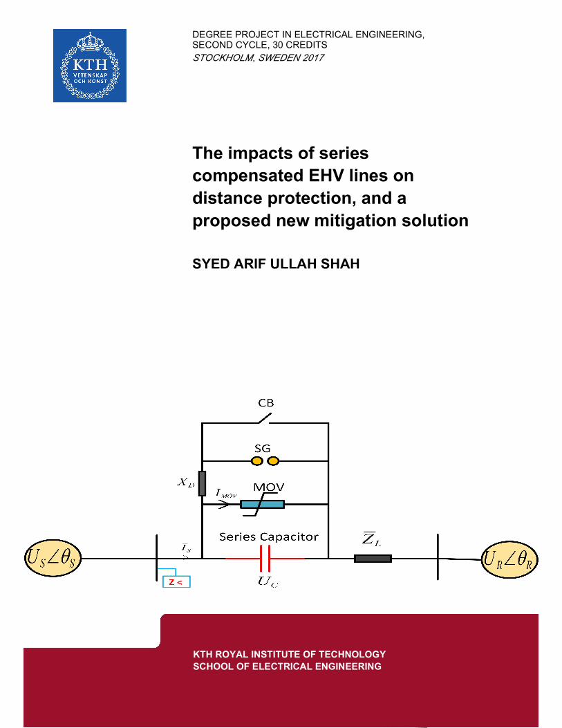
Series compensation is extensively applied to the transmission lines to increase the power transfer
capability of transmission lines, reduce transmission losses, improve voltage profiles, and improve
power oscillation damping and transient stability of power systems. But it modifies the apparent
impedance of the transmission lines during fault conditions and might cause the distance protection
of transmission lines to encounter directional discrimination issues and reach problems. The non-
linear characteristic of metal oxide varistor in series compensation model creates further
complexity to the fault analysis and might affects the performance of conventional distance
protection scheme. The distance protection issues in the series compensated lines need to be
addressed for the reliable and sustainable operation of power system.
The directional discrimination issues related to current inversion and voltage inversion
phenomenon, and reach problems related to sub-synchronous oscillation phenomenon are
addressed in this thesis report. This report aims to analyse the impacts of series compensation on
the performance of conventional distance relays, and proposes a new protection solution to
mitigate the shortcomings of distance relays in the series compensated lines. The proposed new
protection solution includes: new tripping characteristic of quadrilateral distance relays to cope
with the steady-state reach problems due to current or voltage inversion, and a new high-pass
filtering technique to handle the transient reach problems due to SSO.
The proposed new protection algorithm is developed in MATLAB. The performance of new
protection algorithm is evaluated by simulating a 500 kV two-source power system with a 200 km
series compensated line in EMTDC/ PSCAD (Manitoba Hydro). The proposed new protection
solution is found to be beneficial.
Keywords: Series compensation, metal oxide varistor, voltage inversion, current inversion,
sub-synchronous oscillation, quadrilateral characteristic distance relay, digital high-pass filter.

iv
Abstrakt
Seriekompensation tillämpas i stor utsträckning på överföringsledningarna för att öka
överföringsförmågan hos överföringsledningar, minska överföringsförluster, förbättra
spänningsprofiler och förbättra effektdämpning och övergående stabilitet hos elsystem. Men det
ändrar transmissionslinjernas uppenbara impedans under felförhållanden och kan orsaka att
distansskydd för överföringsledningarna stöter på diskrimineringsproblem och uppnår problem.
Den icke-linjära egenskapen hos metalloxidvaristor i seriekompensationsmodell skapar ytterligare
komplexitet för felanalysen och kan påverka prestandan hos konventionella distansskyddssystem.
Distansskydd problemen i seriekompenserade linjer måste lösas för en pålitlig och hållbar drift av
elsystemet.
De riktningsdiskrimineringsproblem som är relaterade till det aktuella inversions- och
spänningsinversionsfenomenet och uppnår problem relaterade till subsynkron oscillationsfenomen
tas upp i denna avhandlingsrapport. Denna rapport syftar till att analysera effekterna av
seriekompensation för prestanda hos konventionella distansreläer och föreslår en ny skyddslösning
för att mildra bristerna i distansreläerna i seriekompenserade linjer. Den föreslagna nya
skyddslösningen innefattar: Ny utlösningskaraktäristik för fyrsidig distansreläer för att klara
avståndet med stillastående / räckvidden på grund av ström- eller spänningsinversion och en ny
högpassfiltreringsteknik för hantering av övergående över- Nå problem på grund av SSO.
Den föreslagna nya skyddsalgoritmen har utvecklats i MATLAB. Utförandet av den nya
skyddsalgoritmen utvärderas genom simulering av ett 500 kV två-källa kraftverk med en 200 km
serie kompenserad linje i EMTDC / PSCAD (Manitoba Hydro). Den föreslagna nya
skyddslösningen har visat sig vara fördelaktig.
Nyckelord: Seriekompensation, metalloxidvaristor, spänningsinversion, ströminversion,
subsynkron oscillation, fyrsidig karakteristiskt distansrelä, digitalt högpassfilter.

v
DEDICATION
I would like to dedicate this piece of work to my family and spouse for their love and support
throughout this journey, specially to my cute and loving kids Syed Taqwim Arif, Syed Ibrahim
Arif and Syed Abdul Ahad for their endless love.

vi

vii
Acknowledgement
This thesis report is the result of degree project work in EI270X Electrotechnical Theory and
Design, which is the fulfilment of Master degree program in Electric Power Engineering at
Kungliga Tekniska Högskolan (KTH) Royal Institute of Technology Stockholm-Sweden. This
project is a cooperation between KTH and ABB. The project work is carried out at ABB Corporate
Research Center (SECRC) under Power System Development Team in Västerås-Sweden.
I would like to acknowledge my examiner Professor Hans Edin for the approval of this degree
project.
I am grateful to my supervisor Jianping Wang at ABB who introduced me into the real research
world and provided me an opportunity to carry out this interesting and challenging project in the
world’s leading relays manufacturing, automation and power company ABB under his kind
supervision.
I am thankful to my supervisor Nathaniel Taylor at KTH for his encouragement, motivation and
suggestions in this project work.
I would like to express gratitude to my additional supervisor Youyi Li at ABB for his technical
support and innovative skills.
I would also like to appreciate Monika Koerfer at ABB for her logistic support during this project.
Finally, I would like to thank my friends at ABB and KTH for their encouragement and good
company.
Syed Arif Ullah Shah
June 2017
KTH- Stockholm

viii

ix
List of Abbreviations
FSC Fixed Series Capacitor
TCSC Thyristor Controlled Series Compensator
SC Series Compensation
MOV Metal Oxide Varistor
EHV Extra-High Voltage
UHV Ultra-High Voltage
PMU Phasor Measurement Unit
FFT Fast Fourier Transform
SSO Sub-Synchronous Oscillation
VT Voltage Transformer
CT Current Transformer
SIR Source to line Impedance Ratio

x
xi
Contents
Abstract ......................................................................................................................................... iii
DEDICATION............................................................................................................................... v
Acknowledgement ....................................................................................................................... vii
List of Abbreviations ................................................................................................................... ix
Chapter 1: Introduction and Literature Survey ........................................................................ 1
1.1 Background ...................................................................................................................... 1
1.2 Literature review .............................................................................................................. 2
1.3 Existing protection solutions ............................................................................................ 3
1.3.1 Memory polarized directional comparator................................................................ 3
1.3.2 Multi-input comparator approach and direct trip scheme ......................................... 3
1.3.3 Adaptive dynamic distance reach control strategy ................................................... 4
1.4 Problem Definition ........................................................................................................... 4
1.5 Aim and Objectives .......................................................................................................... 5
1.6 Methodology .................................................................................................................... 5
1.7 Scenarios .......................................................................................................................... 5
1.8 Thesis outline ................................................................................................................... 6
Chapter 2: Principle of Distance Protection ............................................................................... 9
2.1 Overview of distance protection scheme ......................................................................... 9
2.2 Protection zones ............................................................................................................... 9
2.3 Impedance measurements .............................................................................................. 11
2.3.1 Forward Faults ........................................................................................................ 11
2.3.2 Backward Faults...................................................................................................... 15
2.4 Impacts of fault resistance .............................................................................................. 16
Chapter 3: Impedance Locus and Series Compensation Model ............................................. 19
3.1 Overview of SC .............................................................................................................. 19
3.2 Power transfer capability ................................................................................................ 19
3.3 Locus of load and line impedance in R-X diagram ........................................................ 21
3.4 Series Compensation Model........................................................................................... 22
3.4.1 MOV setting............................................................................................................ 23
xii
3.4.2 Equivalent impedance of SC model ........................................................................ 24
3.5 Impacts of MOV............................................................................................................. 25
3.5.1 High-current faults .................................................................................................. 25
3.5.2 Medium-current faults ............................................................................................ 26
3.5.3 Low-current faults ................................................................................................... 27
Chapter 4: Special phenomena in series compensated lines ................................................... 29
4.1 Current inversion ............................................................................................................ 30
4.1.1 Impacts of current inversion on conventional distance relay: ................................ 32
4.2 Voltage inversion ........................................................................................................... 33
4.2.1 Impacts of voltage inversion on conventional distance relay ................................. 34
4.2.2 Conditions for the voltage inversion ....................................................................... 35
4.2.3 Impacts of source impedance on current and voltage inversion ............................. 36
4.3 Sub-Synchronous Oscillation (SSO) .............................................................................. 37
4.3.1 Impacts of SSO on conventional distance relay ..................................................... 38
Chapter 5: Impacts of Series Compensation on Distance Relays ........................................... 41
5.1 Impacts of a series capacitor on the impedance measurements ..................................... 41
5.1.1 Phase-to- ground fault ............................................................................................. 41
5.1.2 Phase-to-phase fault ................................................................................................ 42
5.2 Impact of MOV operation on the impedance measurement .......................................... 43
5.3 VT is installed before SC ............................................................................................... 44
5.3.1 Impacts on conventional distance relay .................................................................. 45
5.4 VT is installed behind SC .............................................................................................. 47
5.4.1 Impacts on conventional distance relay .................................................................. 48
5.5 Problems of SC for conventional distance relays........................................................... 50
Chapter 6: Proposed New Mitigation Solutions ....................................................................... 51
6.1 New mitigation solution ................................................................................................. 51
6.1.1 New characteristic of quadrilateral distance relay .................................................. 51
6.1.2 Digital high-pass filter ............................................................................................ 54
Chapter 7: Testing and Simulation Results .............................................................................. 57
7.1 Performance of proposed distance relay ........................................................................ 57
7.1.1 Forward Faults ........................................................................................................ 57

xiii
7.1.2 Backward Faults...................................................................................................... 65
Chapter 8: Conclusions .............................................................................................................. 69
8.1 Main Conclusions ........................................................................................................... 69
8.2 Future research and Recommendation ........................................................................... 70
Appendix-1: Power System Modeling ..................................................................................... - 1 -
A1.1 PSCAD Model of Power System ................................................................................... - 1 -
A1.2 Modeling of transmission line ........................................................................................ - 1 -
Appendix-2................................................................................................................................. - 5 -
Appendix-3................................................................................................................................. - 7 -
A3.1 System Data .................................................................................................................... - 7 -
A3.2 Data of power sources at sending and receiving end ..................................................... - 7 -
A3.3 Rating of series capacitor and MOV .............................................................................. - 7 -
A3.4 Data of EHV transmission line ....................................................................................... - 7 -
References .................................................................................................................................. - 9 -
Biography................................................................................................................................. - 13 -

xiv
xv
List of Tables
Table 1-1: Numerical distance relays for series compensated lines by different relay
manufacturers .................................................................................................................................. 3
Table 3-1: Typical range of fault current for different fault condition ......................................... 25
Table 5-1: Value of SIR for strong and weak source .................................................................... 44
Table A3-1: Parameters of line conductor and ground wire ....................................................... - 7 -

xvi
1
Chapter 1
Introduction and Literature Survey
This chapter begins with the brief introduction of series compensation in long transmission
corridors and its impacts on existing distance relays, followed by a literature review showing the
huge research on the protection issues in the series compensated lines. Existing industrial distance
protection solutions for series compensated lines are also addressed in this chapter. This chapter
also includes the brief definition of problem, aim and objectives, and methodology of this degree
project. Finally, the chapter is concluded with an overview of simulation results and scenarios.
1.1 Background
The world's population is expected to reach 7 billion people, and the energy demand is anticipated
to increase by 71% between 2012-2040 in non-OECD (Organisation for Economic Co-operation
and Development) countries [1]. This drives power engineers to generate and transmit maximum
possible power through the long transmission lines to meet the fast-growing demands of electric
power. The strong public and political opposition as well as high infrastructure costs for building
new transmission lines drives the power engineer to install Series Compensation (SC) in Extra
High Voltage/ Ultra High Voltage (EHV/ UHV) transmission lines. SC is achieved by integrating
a Fixed Series Capacitor (FSC) or Thyristor Controlled Series Compensator (TCSC) in series with
the transmission line, each with its own advantages [2].
The benefits of SC include: enhanced power transfer capability of bulk transmission corridors,
improved voltage profile over the transmission lines, reduced transmission losses, enhanced power
flow control over the transmission lines, and improved power oscillation damping and transient
stability of power system [3-6].
High fault current through the series capacitor causes overvoltage across it. A series capacitor is
sensitive to overvoltage and it is uneconomical to design the series capacitor to withstand such
overvoltage during fault conditions. Therefore, a series capacitors is always accompanied by metal
oxide varistor (MOV). A MOV takes the advantages of non-linear resistance characteristic of zinc
oxide to protect the series capacitor against overvoltage during fault conditions [7-8].
A numerical distance relay is one of the feasible and reliable protection solutions to protect EHV/
UHV transmission against any fault type [9-10]. Distance relays use the local voltage and current
at the relay position to compute the apparent impedance, and detect the fault conditions by
comparing the computed apparent impedance with the relay setting [11].
The integration of SC in transmission line brings several protection challenges and problems
including directional discrimination issues and reach problems for distance relays [3], [6], [8],
[12], [13-16].

2
It is possible to correct and adjust the setting of the distance relays for series compensated lines if
the series capacitor always remains in the fault loop, but the operation of the non-linear MOV
modifies the apparent impedance of the transmission line during fault conditions, which affects
the performance of the distance protection scheme and adds further complexity to the fault analysis
and distance relay operation. During high-current fault conditions, the MOV conducts and
bypasses the series capacitor thereby changing the apparent impedance of transmission line from
its compensated impedance to its uncompensated impedance. During low-current fault conditions,
MOV does not conduct and the series capacitor remains in the fault loop, thereby modifying the
apparent impedance of the transmission lines. Low-current fault conditions might cause under-
reach and over-reach problems, and directional discrimination issues for conventional distance
relays.
Thus, a series compensated line affects not only the performance of a distance protection scheme
but also presents technical challenges to protection engineers and researchers to find new
protection solutions and mitigation techniques to handle such problems.
1.2 Literature review
Reviews showing the impacts of series compensated line on distance protection are presented in
[3], [6], [8], [13-14].
Adaptive protection scheme to correct the tripping boundary of distance relays in MOV protected
series compensated lines is proposed in [17-19], based on compensation of voltage drops across
series capacitors. This protection scheme is one of the effective approaches to handle the limitation
of distance relays in the series compensated lines but this scheme requires additional Voltage
Transformer (VT) across the SC. A slightly different adaptive protection algorithm is proposed in
[20], which considers the compensation voltage in the impedance calculation of the fault loop
depending upon the direction of fault current. But this protection scheme needs a reliable
communication channel, and voltage and current information at both ends.
Memory voltage polarization uses pre-fault voltage during voltage inversion and is one of the most
common solutions to handle directional problems, or voltage inversion issues [3], [8]. However, a
new directional relaying algorithm based on voting technique using an integrated approach is
proposed in [21] to handle directional issues for distance relay. A slightly different approach to
cope with directional problems is used in [22], based on the phase change in positive sequence
current and magnitude change in positive sequence voltage.
Current or voltage inversion leads to directional discrimination issues [12], [22] for conventional
distance relays. Sub-Synchronous Oscillation (SSO) leads to transient over-reach problems for
conventional distance relays [8], [23] which might slow down the operation for distance relays
[16].
Prony algorithm based filtering technique is proposed in [15] to cope with impedance measurement
errors due to SSO.

3
A backup distance protection scheme for the series compensated lines based on mutual impedance
between phases is proposed in [24]. But this protection scheme considers only un-balanced faults.
A travelling wave based protection scheme is proposed in [25] which offers high speed protection,
but the protection scheme faces some limitation during slowly evolving faults. Artificial neural
networks based distance protection is proposed in [26-27], but this protection algorithm requires
huge and complex training data.
Non-distance protection schemes for series compensated lines include: novel unit protection
scheme [28], pilot protection scheme [29], fuzzy logic technique using DC line current [30], and
PMU based protection scheme [31].
1.3 Existing protection solutions
Different relay manufacturers already use distance relays for series compensated lines.
Table 1-1 outlines the numerical distance relays for series compensated lines by different relay
manufacturers.
Table 1-1: Numerical distance relays for series compensated lines by different relay manufacturers
Relay Vendors Distance relays
General Electric (GE) GE D90Plus [16]
Schweitzer Engineering Labs, Inc. (SEL) SEL-421-5 [3]
ABB REL 670 [32]
Siemens SIPROTEC 4 7SA522 [33]
Almost all the distance relays use hybrid protection scheme to protect series compensated line.
1.3.1 Memory polarized directional comparator
GE, SEL, ABB and Siemens relay manufacturers use 100% memory polarized directional
comparators to handle voltage inversion issues [16], [8]. Memory voltage polarization uses pre-
fault voltage during voltage inversion. This guarantees the distance relays to operate during
forward faults and fail to pick-up during backward faults which is the disadvantage of using
memory voltage polarization.
1.3.2 Multi-input comparator approach and direct trip scheme
GE and SEL relay manufacturers use multi-input comparator approach to handle the current
inversion issues. Multi-input comparator approach uses fault-loop current for phase and ground
distance protection, and negative and zero sequence currents for the ground element [16]. Since
the fault current shifts by more than 90 degree during current inversion, so the distance relays
might not operate during current inversion for short period. So, the vendors of these relays
recommend to use high speed overcurrent protection for direct tripping during current inversion.
4
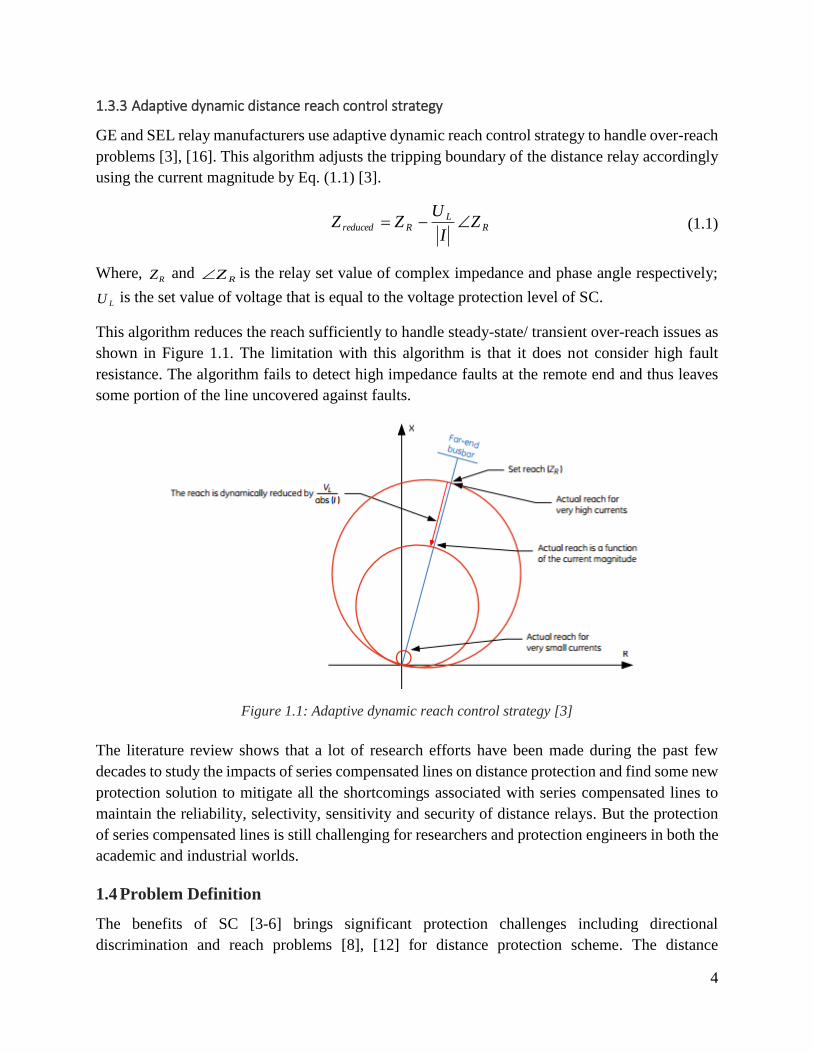
1.3.3 Adaptive dynamic distance reach control strategy
GE and SEL relay manufacturers use adaptive dynamic reach control strategy to handle over-reach
problems [3], [16]. This algorithm adjusts the tripping boundary of the distance relay accordingly
using the current magnitude by Eq. (1.1) [3].
RL
Rreduced ZI
UZZ (1.1)
Where, RZ and
RZ is the relay set value of complex impedance and phase angle respectively;
LU is the set value of voltage that is equal to the voltage protection level of SC.
This algorithm reduces the reach sufficiently to handle steady-state/ transient over-reach issues as
shown in Figure 1.1. The limitation with this algorithm is that it does not consider high fault
resistance. The algorithm fails to detect high impedance faults at the remote end and thus leaves
some portion of the line uncovered against faults.
Figure 1.1: Adaptive dynamic reach control strategy [3]
The literature review shows that a lot of research efforts have been made during the past few
decades to study the impacts of series compensated lines on distance protection and find some new
protection solution to mitigate all the shortcomings associated with series compensated lines to
maintain the reliability, selectivity, sensitivity and security of distance relays. But the protection
of series compensated lines is still challenging for researchers and protection engineers in both the
academic and industrial worlds.
1.4 Problem Definition
The benefits of SC [3-6] brings significant protection challenges including directional
discrimination and reach problems [8], [12] for distance protection scheme. The distance

5
protective relays might not operate properly during faults on the series compensated lines. An
accurate power system model with series compensated line is required to investigate the impacts
of series compensation on the voltage and current signal at relay position so that some mitigation
techniques or new protection solution is found.
1.5 Aim and Objectives
The overall aim of this degree project is to analyze the impacts of the series compensated EHV
transmission line on the performance of distance protection scheme. The objectives are outlined
as follows:
Develop a PSCAD model of a 500 kV two-source power system with series compensated
EHV line
Investigate the impacts of special phenomena associated with series compensation on the
voltage and current at relay position
Analyse the impacts of SC on the performance of a conventional distance protection
scheme
Propose mitigation techniques and a new protection algorithm to handle the shortcomings
of the distance relays in series compensated lines
1.6 Methodology
This project considers a 500 kV two-source power system with a 200 km EHV transmission line.
Frequency dependent model for transmission line is used to perform accurate transient analysis.
Series compensation is considered at sending bus end. The equivalent power system is modeled in
EMTDC/ PSCAD (Manitoba Hydro) and transient analysis is performed for different MOV
operations and various system operating conditions. The protection algorithm of a quadrilateral
distance relay is developed in MATLAB. The simulation data from PSCAD is exported into
MATLAB and the impacts of series compensation on distance protection is analyzed. A new
setting of the distance relay is proposed to overcome steady-state under-reach and over-reach
problems, and a Butterworth high-pass filter is proposed and implemented to cope with transient
over-reach problems of distance relays in series compensated lines.
1.7 Scenarios
The impacts of series compensation on distance protection is analyzed for both forward and
backward faults under different system operating conditions. The proposed distance relay
algorithm and performance of Butterworth high-pass filter is tested for forward-backward faults
with different MOV operating conditions, different fault resistance, different fault location, and
different source impedance conditions. Since 80% of faults in power system are phase-to-ground
faults so the simulation results consider phase-to-ground faults to simplify the analysis however

6
the protection algorithm works for all type of faults i.e. phase-to-ground, phase-to-phase, and
three-phase faults.
The block diagram in Figure 1.2 gives an overall view of simulation results and scenarios to be
analyzed.
Figure 1.2: Overview of simulation results and scenarios to be analyzed
1.8 Thesis outline
This report focuses on the effort involved in analyzing the impacts of series compensation on
conventional distance protection, and developing new protection algorithm to protect series
compensated lines. Directional issues related to the current inversion or voltage inversion
phenomenon, and reach problems related to sub-synchronous oscillation are also addressed in this
report. This report is organized in eight chapters as follows:
Chapter 1 gives a brief introduction to the background, literature review, problem description, aim
and objectives, methodology, and the overview of simulation results followed by thesis outline.
Chapter 2 gives an overview of conventional distance relays as well as the typical protection zones,
and tripping characteristic for phase-to-ground/ phase-to-phase faults during both forward/
backward faults.
7
Chapter 3 presents series compensation model followed by the impacts of MOV operation during
different fault conditions.
Chapter 4 explains special phenomena associated with series compensated lines and its impacts on
the conventional distance relays.
Chapter 5 shows the impacts of series compensation on the characteristic of line impedance/
performance of conventional distance relays for different location of VT or series compensation.
Chapter 6 presents the proposed new mitigation solution to handle the shortcomings and protection
issues of distance relays in the series compensated lines.
Chapter 7 focuses on the simulation results to verify the proposed new protection scheme during
different phenomena for various forward and backward faults. Finally, the overall conclusions of
this report are presented in chapter 8, and this chapter ends with future research and general
recommendation of author.

8
9
Chapter 2
Principle of Distance Protection
This chapter begins with the brief overview of conventional distance protection scheme, which is
then followed by protection zones of typical distance relay. Impedance measurements during both
phase-to-ground and phase-to-phase fault loops are explained for both forward and backward
faults. The tripping characteristic of typical conventional distance relay is defined as well for
forward and backward faults. The chapter ends with the impacts of fault resistance on impedance
measurements.
2.1 Overview of distance protection scheme
In order to analyze intelligently the impacts of series compensated transmission lines on distance
protection, it is necessary to have firm understanding about the operational principles of
conventional distance protection scheme for uncompensated transmission line. It is then easy to
extend the knowledge for series compensated transmission line to analyze the impacts of SC on
the performance of existing distance relays and resolve the additional relaying problems caused
by the integration SC.
Distance relays are widely used to protect long distance transmission lines [9-10]. The operational
principle of distance protection scheme is based on calculation of impedance from the voltage and
current signal at relay position and compares the computed value of impedance with the pre-
determined or set value of relay. Distance relay detects a fault condition if the computed impedance
lies inside the characteristic defined by the setting of distance relay. The protection algorithm of
distance relay uses six impedance measuring loops to cover all possible and expected forward and
reverse faults in transmission line; three impedance measuring loops cover phase-to-ground faults
and three impedance measuring loops cover phase-to-phase faults as well as three phase faults
[32].
The two most widely and commonly used characteristics of distance relays are; mho and
quadrilateral characteristic. Distance relay with quadrilateral characteristic provides adequate
coverage to the fault resistance than mho characteristic relay. Quadrilateral characteristic distance
relay can easily detect high impedance faults. This project considers distance relay with the
quadrilateral characteristic.
2.2 Protection zones
The beauty of distance protection is the multi zones protection which offers primary protection as
well as remote backup protection. Distance relay provides instantaneous protection in zone 1 and
delayed protection in other zones. The modern distance relay has 3-5 forward zones and one
reverse protection zone depending upon the type of relay [32].
10
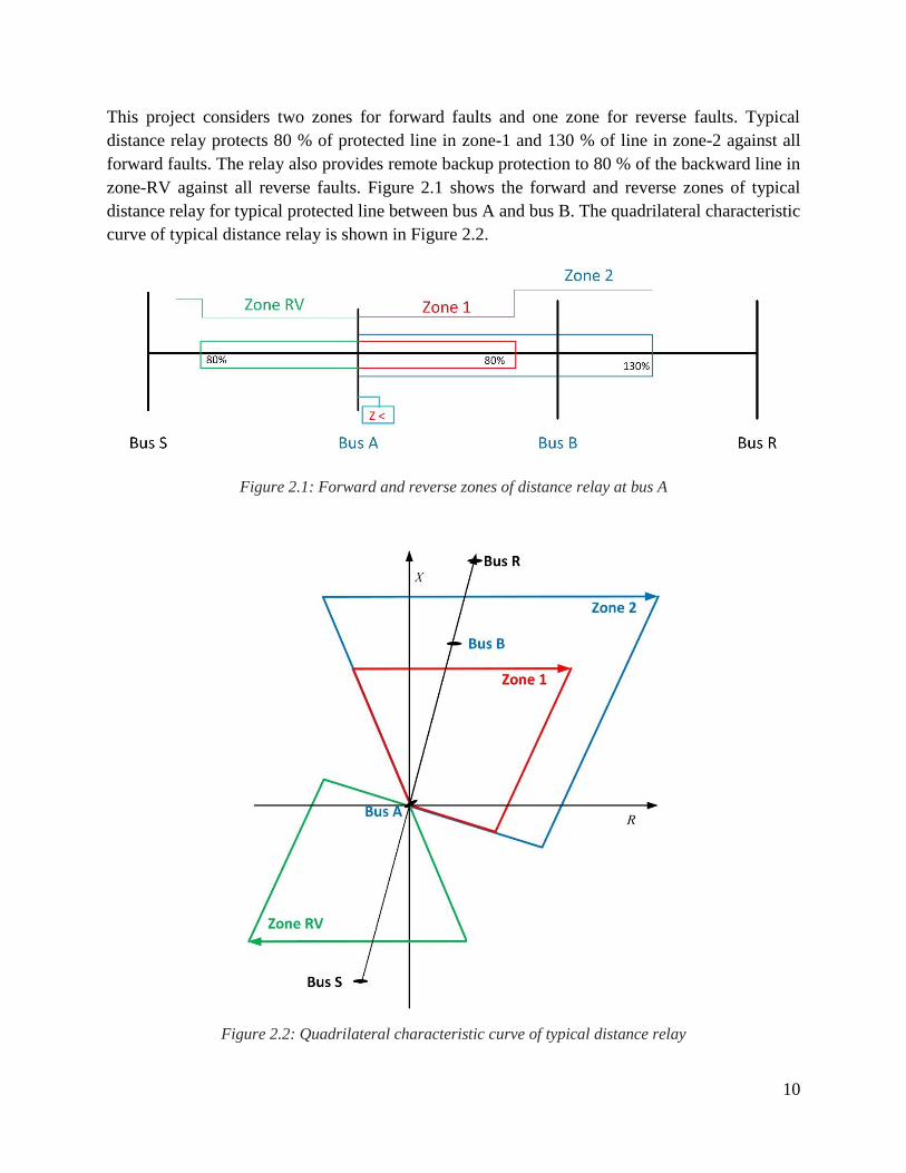
This project considers two zones for forward faults and one zone for reverse faults. Typical
distance relay protects 80 % of protected line in zone-1 and 130 % of line in zone-2 against all
forward faults. The relay also provides remote backup protection to 80 % of the backward line in
zone-RV against all reverse faults. Figure 2.1 shows the forward and reverse zones of typical
distance relay for typical protected line between bus A and bus B. The quadrilateral characteristic
curve of typical distance relay is shown in Figure 2.2.
Figure 2.1: Forward and reverse zones of distance relay at bus A
Figure 2.2: Quadrilateral characteristic curve of typical distance relay

11
As mentioned earlier, the protection algorithm of typical quadrilateral characteristic distance relay
uses six impedance measuring loops to cover all possible and expected forward and reverse faults
in transmission line; three impedance measuring loops cover phase-to-earth faults and three
impedance measuring loops cover phase-to-phase faults as well as three phase faults. To analyze
the factors affecting the impedance characteristic of the line, it is vital to explain first the
impedance measurement of the line during forward/ backward faults in both phase-to-ground and
phase-to-phase fault loops.
2.3 Impedance measurements
Consider a typical EHV transmission line between bus A and bus B in a typical two-source power
system as shown in Figure 2.3.
Figure 2.3: Typical two source power system with EHV transmission line
Where, SU and RU is the source voltage at sending bus S and receiving bus R respectively; SZ
and RZ is the source impedance at sending and receiving end respectively; LZ is the impedance
of protected EHV transmission line; sI and RI is the contribution of fault current from two
sources; AU and BU is the phasor voltage at bus A and bus B respectively; R1 is the distance relay
installed at bus A.
To calculate the impedance of transmission line during phase-to-ground and phase-to-phase faults
for both forward and backward faults, we consider forward fault occurring at P % of protected line
impedance from bus A; and backward fault occurring at end of backward line as shown in Figure
2.3. The forward and backward faults occur independently of each other.
2.3.1 Forward Faults
2.3.1.1 Phase-to- ground fault
During phase-to-ground faults, the power system can be modelled as positive, negative and zero
sequence network as shown in Figure 2.4.

12
Figure 2.4: Positive, negative and zero sequence model of power system during phase-to-ground fault
Where, ( 1_SZ , 2_SZ , 0_SZ ); ( 1_LZ , 2_LZ , 0_LZ ); and ( 1_RZ , 2_RZ , 0_RZ ); is the positive, negative
and zero sequence impedance of; sending source; line; and receiving source respectively, such that
2_1_ SS ZZ ; 2_1_ LL ZZ ; 2_1_ RR ZZ .
0_2_1_ ,, SSS III and 0_2_1_ ,, RRR III are the sequence currents of sending and receiving
source, such that SSSS IIII 3
10_2_1_ ; RRRR IIII
3
10_2_1_ ; and fR is the fault
resistance.
During phase-to-ground fault, the apparent impedance seen by distance relay R1 at bus A is given
by Eq. (2.1).
fRnLL
S
APG RkZZp
I
UZ _1_ (2.1)
Where, 3
1_0_
_
LL
nL
ZZZ
[33]; and
S
RR
I
Ik 1
In general, the apparent impedance of transmission line during phase-to-ground fault without SC
is given by Eq. (2.2).
nLLNSC ZZZ _1_ (2.2)
13
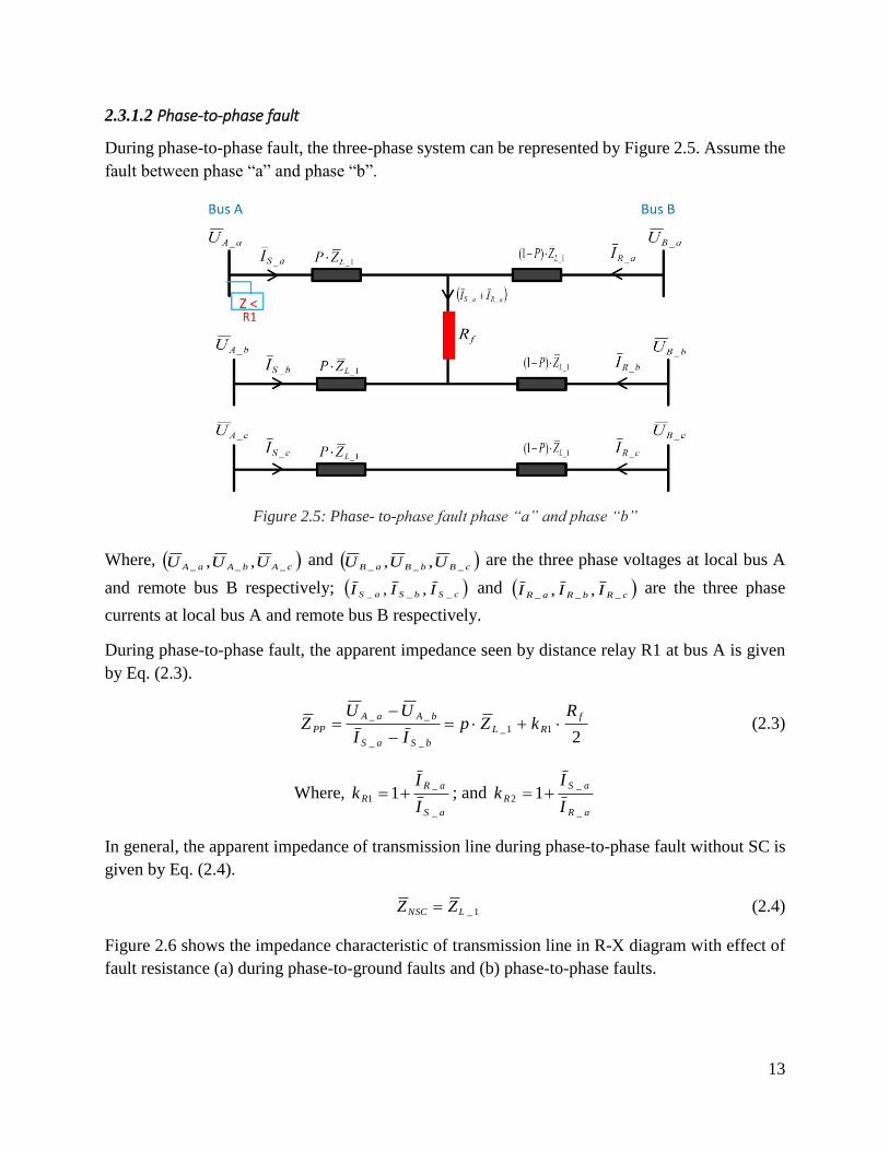
2.3.1.2 Phase-to-phase fault
During phase-to-phase fault, the three-phase system can be represented by Figure 2.5. Assume the
fault between phase “a” and phase “b”.
Figure 2.5: Phase- to-phase fault phase “a” and phase “b”
Where, cAbAaA UUU ___ ,, and cBbBaB UUU ___ ,, are the three phase voltages at local bus A
and remote bus B respectively; cSbSaS III ___ ,, and cRbRaR III ___ ,, are the three phase
currents at local bus A and remote bus B respectively.
During phase-to-phase fault, the apparent impedance seen by distance relay R1 at bus A is given
by Eq. (2.3).
2
11_
__
__ f
RL
bSaS
bAaA
PP
RkZp
II
UUZ
(2.3)
Where, aS
aR
RI
Ik
_
_
1 1 ; and aR
aS
RI
Ik
_
_
2 1
In general, the apparent impedance of transmission line during phase-to-phase fault without SC is
given by Eq. (2.4).
1_LNSC ZZ (2.4)
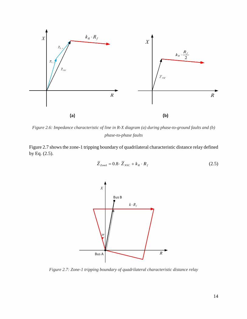
Figure 2.6 shows the impedance characteristic of transmission line in R-X diagram with effect of
fault resistance (a) during phase-to-ground faults and (b) phase-to-phase faults.
14
Figure 2.6: Impedance characteristic of line in R-X diagram (a) during phase-to-ground faults and (b)
phase-to-phase faults
Figure 2.7 shows the zone-1 tripping boundary of quadrilateral characteristic distance relay defined
by Eq. (2.5).
fRNSCZone RkZZ 8.01 (2.5)
Figure 2.7: Zone-1 tripping boundary of quadrilateral characteristic distance relay
15
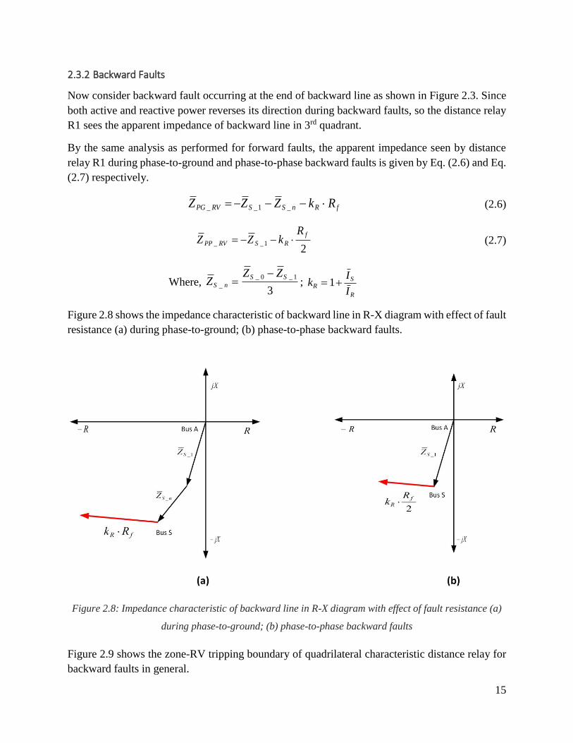
2.3.2 Backward Faults
Now consider backward fault occurring at the end of backward line as shown in Figure 2.3. Since
both active and reactive power reverses its direction during backward faults, so the distance relay
R1 sees the apparent impedance of backward line in 3rd quadrant.
By the same analysis as performed for forward faults, the apparent impedance seen by distance
relay R1 during phase-to-ground and phase-to-phase backward faults is given by Eq. (2.6) and Eq.
(2.7) respectively.
fRnSSRVPG RkZZZ _1__ (2.6)
2
1__
f
RSRVPP
RkZZ (2.7)
Where, 3
1_0_
_
SS
nS
ZZZ
;
R
SR
I
Ik 1
Figure 2.8 shows the impedance characteristic of backward line in R-X diagram with effect of fault
resistance (a) during phase-to-ground; (b) phase-to-phase backward faults.
Figure 2.8: Impedance characteristic of backward line in R-X diagram with effect of fault resistance (a)
during phase-to-ground; (b) phase-to-phase backward faults
Figure 2.9 shows the zone-RV tripping boundary of quadrilateral characteristic distance relay for
backward faults in general.

16
Figure 2.9: Zone-RV tripping boundary of quadrilateral characteristic distance relay for backward faults
2.4 Impacts of fault resistance
Fault resistance is always associated with the occurrence of fault. Fault resistance is basically the
combination of arc resistance, tower resistance and tower footing resistance given by Eq. (2.8).
towerarcf RRR (2.8)
Where, fR is fault resistance; arcR is arc resistance, and towerR is tower resistance.
Arc resistance can be calculated by Warrington’s formula given by Eq. (2.9) [34].
4.1
28707
I
LRarc
(2.9)
Where, L is length of arc (meter) and I is the RMS value of arc current (amperes).
However, in comparison with Warrington’s formula, a new formula for arc resistance is derived
in [35] given by Eq. (2.10) and Eq. (2.11).
I
LRarc
5.1350
4.10801 (2.10)
LII
Rarc
22
6.45013.855 (2.11)
17
The contribution of fault currents by both sending and receiving end source in two-source power
system introduce the complex quantity in fault resistance. The fault currents of both sources in the
fault resistance produce the capacitive or inductive effects depending upon the phasor relationship
of both currents. Thus, the overall impact of fault currents by both sources on fault resistance is
complex quantity thereby yielding the fault impedance as a resultant quantity given by Eq. (2.12).
The fault impedance sometime causes over-reach problems if both currents are out of phase.
f
S
Rf R
I
IZ
1 (2.12)

18
19
Chapter 3
Impedance Locus and Series Compensation Model
The overall objective of this chapter is to present a brief overview of Series Compensation (SC) in
long transmission corridors, followed by the power transfer capability of series compensated lines.
This chapter also gives a brief overview showing the impacts of a series capacitor on the
characteristic of transmission lines. SC model including protective circuit for a series capacitor is
also addressed in this chapter. The chapter is finally concluded on the impacts of MOV operation
during different fault conditions.
3.1 Overview of SC
In 1928, the world first SC system was installed on the emerging US transmission grid by GE,
while ABB has implemented the first SC in 1950 and continued to refine and develop this
technology in such a way that today ABB leads the world in SC and effective power transmission.
The basic objective of SC is to reduce the inductive reactance of transmission line and increase the
power transfer capability of transmission line [6] [36]. SC reduces the cost significantly for the
transmission lines typically greater than 200 miles as compared to the building of a new equivalent
transmission lines [6]. Other advantages of SC include: improved voltage profile, power flow
control over the transmission lines, reduced transmission losses, improved power oscillation
damping and transient stability of power system [3-6]. The advantages of SC are associated with
phenomena: current inversion, voltage inversion, and SSO which leads to directional
discrimination issues and reach problems for conventional distance relays [8] [12].
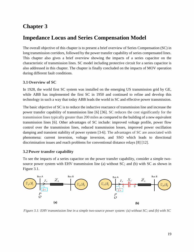
3.2 Power transfer capability
To see the impacts of a series capacitor on the power transfer capability, consider a simple two-
source power system with EHV transmission line (a) without SC; and (b) with SC as shown in
Figure 3.1.
Figure 3.1: EHV transmission line in a simple two-source power system: (a) without SC; and (b) with SC

20
Where, SSU and RRU is the phasor voltage at local bus A and remote bus B respectively;
LZ is the impedance of transmission line; CX is the capacitance of a series capacitor; sI is the
current flowing in transmission line.
The active and reactive power flow through the lossless transmission line without SC is given by
Eq. (3.1) and Eq. (3.2) respectively.
sin
L
RS
X
UUP (3.1)
cos
L
S
X
UUQ (3.2)
Where, P and Q is the active and reactive power flow over transmission line; )( RS and
)( RS UUU is the angle difference and voltage difference respectively between local bus A
and remote bus B.
Keeping the same voltage phasors at local and remote bus, the power transfer capability of
transmission line can be enhanced by reducing the inductive reactance of the line. This is achieved
by integrating a series capacitor in transmission line as shown in Figure 3.1(b). The active and
reactive power flow through the lossless transmission line with SC is given by Eq. (3.3) and Eq.
(3.4) respectively.
sin
CL
RS
XX
UUP (3.3)
cos
CL
S
XX
UUQ (3.4)
The power transfer capability depends upon the degree of series compensation. Degree of series
compensation is the ratio of capacitive reactance to the inductive reactance of transmission line
and can be expressed mathematically by Eq. (3.5).
L
C
X
Xk (3.5)
Eq. (3.3) can also be expressed in terms of compensation level by Eq. (3.6).
sin
1
kX
UUP
L
RS (3.6)
The power transfer doubles for 50% compensation level.
21
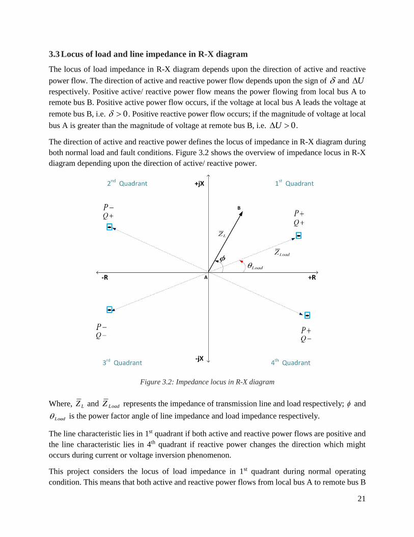
3.3 Locus of load and line impedance in R-X diagram
The locus of load impedance in R-X diagram depends upon the direction of active and reactive
power flow. The direction of active and reactive power flow depends upon the sign of and U
respectively. Positive active/ reactive power flow means the power flowing from local bus A to
remote bus B. Positive active power flow occurs, if the voltage at local bus A leads the voltage at
remote bus B, i.e. 0 . Positive reactive power flow occurs; if the magnitude of voltage at local
bus A is greater than the magnitude of voltage at remote bus B, i.e. 0U .
The direction of active and reactive power defines the locus of impedance in R-X diagram during
both normal load and fault conditions. Figure 3.2 shows the overview of impedance locus in R-X
diagram depending upon the direction of active/ reactive power.
Figure 3.2: Impedance locus in R-X diagram
Where, LZ and LoadZ represents the impedance of transmission line and load respectively; and
Load is the power factor angle of line impedance and load impedance respectively.
The line characteristic lies in 1st quadrant if both active and reactive power flows are positive and
the line characteristic lies in 4th quadrant if reactive power changes the direction which might
occurs during current or voltage inversion phenomenon.
This project considers the locus of load impedance in 1st quadrant during normal operating
condition. This means that both active and reactive power flows from local bus A to remote bus B
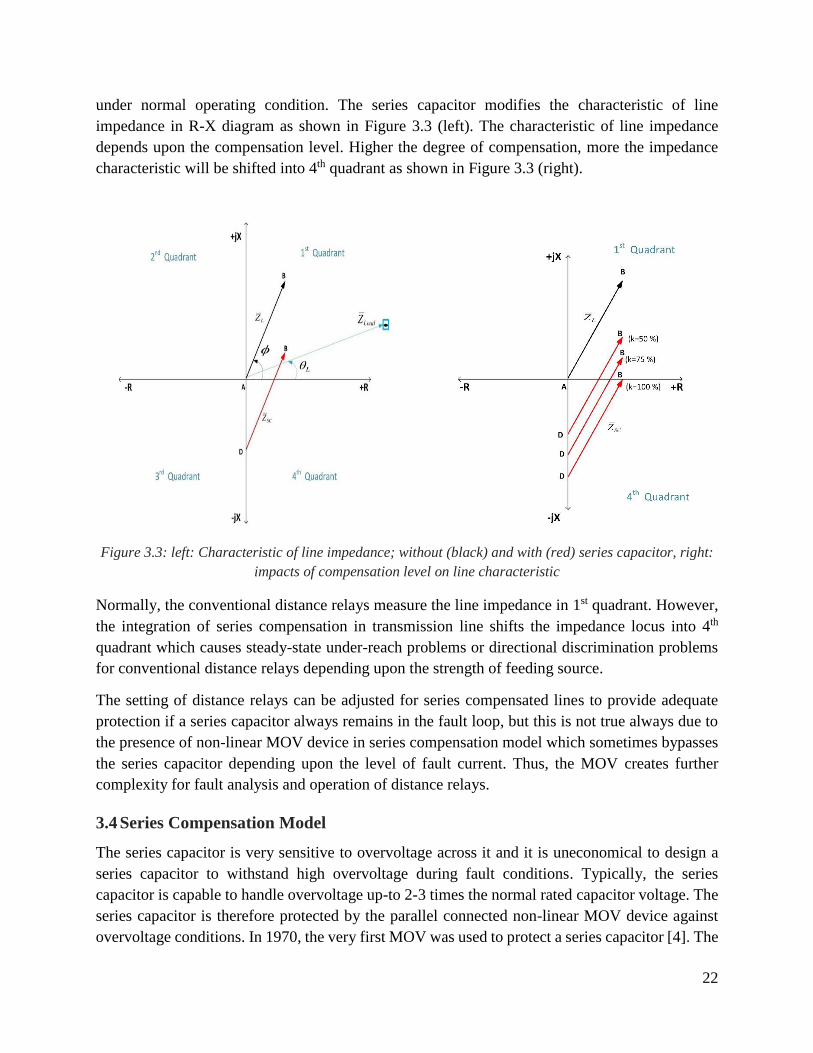
22
under normal operating condition. The series capacitor modifies the characteristic of line
impedance in R-X diagram as shown in Figure 3.3 (left). The characteristic of line impedance
depends upon the compensation level. Higher the degree of compensation, more the impedance
characteristic will be shifted into 4th quadrant as shown in Figure 3.3 (right).
Figure 3.3: left: Characteristic of line impedance; without (black) and with (red) series capacitor, right:
impacts of compensation level on line characteristic
Normally, the conventional distance relays measure the line impedance in 1st quadrant. However,
the integration of series compensation in transmission line shifts the impedance locus into 4th
quadrant which causes steady-state under-reach problems or directional discrimination problems
for conventional distance relays depending upon the strength of feeding source.
The setting of distance relays can be adjusted for series compensated lines to provide adequate
protection if a series capacitor always remains in the fault loop, but this is not true always due to
the presence of non-linear MOV device in series compensation model which sometimes bypasses
the series capacitor depending upon the level of fault current. Thus, the MOV creates further
complexity for fault analysis and operation of distance relays.
3.4 Series Compensation Model
The series capacitor is very sensitive to overvoltage across it and it is uneconomical to design a
series capacitor to withstand high overvoltage during fault conditions. Typically, the series
capacitor is capable to handle overvoltage up-to 2-3 times the normal rated capacitor voltage. The
series capacitor is therefore protected by the parallel connected non-linear MOV device against
overvoltage conditions. In 1970, the very first MOV was used to protect a series capacitor [4]. The
23
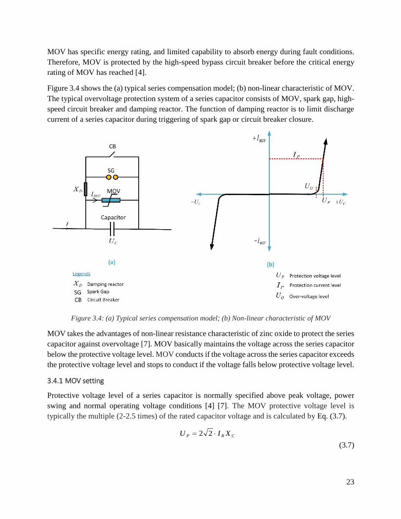
MOV has specific energy rating, and limited capability to absorb energy during fault conditions.
Therefore, MOV is protected by the high-speed bypass circuit breaker before the critical energy
rating of MOV has reached [4].
Figure 3.4 shows the (a) typical series compensation model; (b) non-linear characteristic of MOV.
The typical overvoltage protection system of a series capacitor consists of MOV, spark gap, high-
speed circuit breaker and damping reactor. The function of damping reactor is to limit discharge
current of a series capacitor during triggering of spark gap or circuit breaker closure.
Figure 3.4: (a) Typical series compensation model; (b) Non-linear characteristic of MOV
MOV takes the advantages of non-linear resistance characteristic of zinc oxide to protect the series
capacitor against overvoltage [7]. MOV basically maintains the voltage across the series capacitor
below the protective voltage level. MOV conducts if the voltage across the series capacitor exceeds
the protective voltage level and stops to conduct if the voltage falls below protective voltage level.
3.4.1 MOV setting
Protective voltage level of a series capacitor is normally specified above peak voltage, power
swing and normal operating voltage conditions [4] [7]. The MOV protective voltage level is
typically the multiple (2-2.5 times) of the rated capacitor voltage and is calculated by Eq. (3.7).
CRP XIU 22
(3.7)

24
Where, PU is the protective voltage level; RI is the rated capacitor current; and CX is the
capacitive reactance.
The protective current level can be computed by Eq. (3.8).
RP II 22 (3.8)
MOV conducts when the level of fault current reaches the protective current level and dissipate
energy. MOV has specific energy rating. This means that MOV operates and sends closing signal
to high-speed circuit breaker and bypasses the series capacitor before critical energy rating has
reached. In this project MOV operates in 20 milliseconds (ms) when MOV energy rating or MOV
protective current level is reached. The energy rating, protective current level, and protective
voltage level of typical MOV is defined in Appendix-3.
3.4.2 Equivalent impedance of SC model
The parallel combination of MOV and a series capacitor in a series compensation model presents
an equivalent impedance to the fault loop during fault conditions. Figure 3.5 shows the equivalent
impedance of SC model during fault conditions.
Figure 3.5: Equivalent impedance of SC model during fault
Mathematically, the equivalent impedance of SC model during fault conditions is given by Eq.
(3.9).
eqeqCMOVSCMOV XjRXRZ //_ (3.9)
MOV changes the equivalent impedance in the fault loop depending upon the level of fault current.
This means that the operation of MOV modifies the apparent impedance of fault loop. Therefore,
it is very necessary to analyze the impacts of MOV on the characteristic of line impedance.
25
3.5 Impacts of MOV
The operation of MOV mainly depends upon the level of fault current. The level of fault current
depends upon the source impedance, location of fault and fault resistance. The faults can be
classified as high-current, medium-current and low-current faults depending upon the operation of
MOV/ protective current level. In this project, the protective current level of MOV is assumed to
be 10 kA. This project considers the typical range of fault current for different fault conditions
depending upon the protective current level or MOV operating time. Table 3-1 presents the typical
range of fault current for different fault conditions.
Table 3-1: Typical range of fault current for different fault condition
Fault conditions Fault current (kA)
Low-current faults <10
Medium-current faults 10-20
High-current faults >20
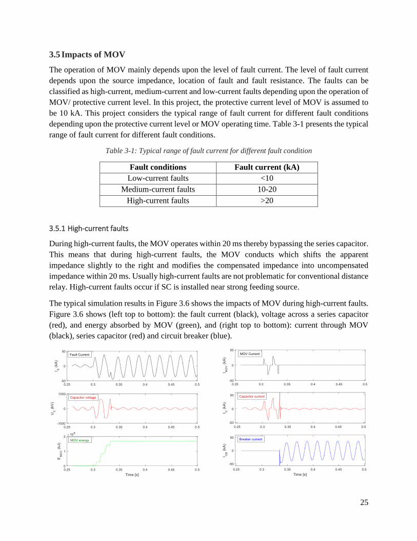
3.5.1 High-current faults
During high-current faults, the MOV operates within 20 ms thereby bypassing the series capacitor.
This means that during high-current faults, the MOV conducts which shifts the apparent
impedance slightly to the right and modifies the compensated impedance into uncompensated
impedance within 20 ms. Usually high-current faults are not problematic for conventional distance
relay. High-current faults occur if SC is installed near strong feeding source.
The typical simulation results in Figure 3.6 shows the impacts of MOV during high-current faults.
Figure 3.6 shows (left top to bottom): the fault current (black), voltage across a series capacitor
(red), and energy absorbed by MOV (green), and (right top to bottom): current through MOV
(black), series capacitor (red) and circuit breaker (blue).

26
Figure 3.6: (left top to bottom): the fault current (black), voltage across a series capacitor (red), and
energy absorbed by MOV (green), and (right top to bottom): current through MOV (black), series
capacitor (red) and circuit breaker (blue)
It can be seen by Figure 3.6 that during typical high-current fault, the MOV bypasses the series
capacitor in 20 ms and the fault current mainly flows through the circuit breaker.
3.5.2 Medium-current faults
During medium-current faults, some of the fault current flows through a series capacitor and some
fault current through the MOV. This reduces the level of series compensation in the equivalent
impedance model during fault conditions, and shifts the impedance locus slightly to the right too.
During medium-current faults, the delayed MOV operation might cause the conventional distance
relay to be blind for faults near SC. A new protection algorithm is required for fast detection of
medium-current faults.
The typical simulation results in Figure 3.7 shows the impacts of MOV during medium-current
faults. Figure 3.7 shows (left top to bottom): the fault current (black) voltage across a series
capacitor (red), and energy absorbed by MOV (green), and (right top to bottom): current through
MOV (black), series capacitor (red) and circuit breaker (blue).
Figure 3.7: (left top to bottom): the fault current (black), voltage across a series capacitor (red), and
energy absorbed by MOV (green), and (right top to bottom): current through MOV (black), series
capacitor (red) and circuit breaker (blue)
It can be seen by Figure 3.7 that during typical medium-current fault, part of fault current flows
through both the MOV and a series capacitor for longer time (120 ms in this case). MOV operates
at 120 ms and hence fast operation of conventional distance relays is not possible under such
conditions.
27
3.5.3 Low-current faults
In low-current faults, the level of fault current is usually below the protective current level. The
MOV acts as open circuit and the fault current mainly flows through a series capacitor thereby
modifying the apparent impedance of the transmission lines. Low-current faults in series
compensated lines lead the distance relays to encounter directional discrimination issues and reach
problems. Low-current faults usually occur at remote end or if SC is installed near weak feeding
source but also can occur during strong feeding source with impedance faults.
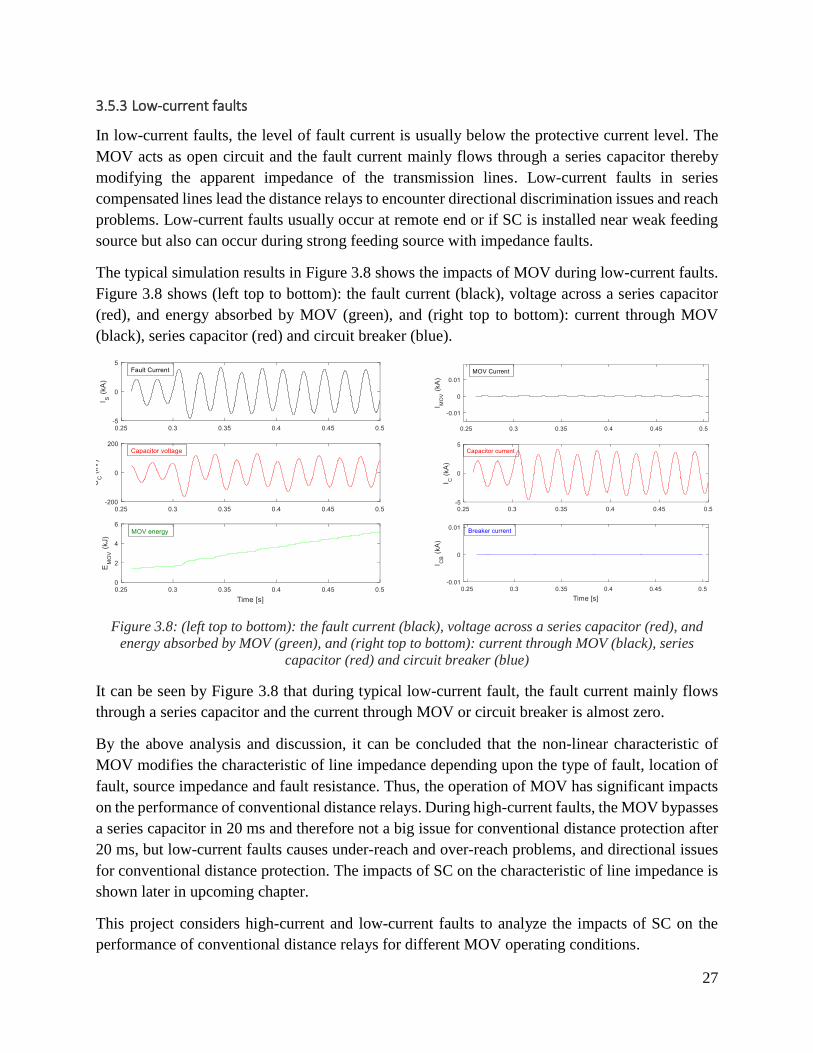
The typical simulation results in Figure 3.8 shows the impacts of MOV during low-current faults.
Figure 3.8 shows (left top to bottom): the fault current (black), voltage across a series capacitor
(red), and energy absorbed by MOV (green), and (right top to bottom): current through MOV
(black), series capacitor (red) and circuit breaker (blue).
Figure 3.8: (left top to bottom): the fault current (black), voltage across a series capacitor (red), and
energy absorbed by MOV (green), and (right top to bottom): current through MOV (black), series
capacitor (red) and circuit breaker (blue)
It can be seen by Figure 3.8 that during typical low-current fault, the fault current mainly flows
through a series capacitor and the current through MOV or circuit breaker is almost zero.
By the above analysis and discussion, it can be concluded that the non-linear characteristic of
MOV modifies the characteristic of line impedance depending upon the type of fault, location of
fault, source impedance and fault resistance. Thus, the operation of MOV has significant impacts
on the performance of conventional distance relays. During high-current faults, the MOV bypasses
a series capacitor in 20 ms and therefore not a big issue for conventional distance protection after
20 ms, but low-current faults causes under-reach and over-reach problems, and directional issues
for conventional distance protection. The impacts of SC on the characteristic of line impedance is
shown later in upcoming chapter.
This project considers high-current and low-current faults to analyze the impacts of SC on the
performance of conventional distance relays for different MOV operating conditions.

28
29
Chapter 4
Special phenomena in series compensated lines
This chapter presents a brief explanation of special phenomena associated with the faults in the
series compensated lines such as current inversion, voltage inversion, and Sub-Synchronous
Oscillation (SSO) and its impacts on conventional distance protection scheme. Current or voltage
inversion leads to directional discrimination issues [12] [22]. SSO causes transient over-reach
problems and slows down the operation of conventional distance relays [8] [13].
To illustrate these phenomena, consider a typical two-source power system with series
compensated line as shown in Figure 4.1. At 0.3 seconds (s) the fault occurs at p% of total line
impedance.
Where, SX , CX , and LX is the source reactance at sending end, capacitive reactance of SC, and
inductive reactance of protected line respectively. The factors affecting the characteristic of line
impedance in the fault loop are listed as follows:
Source impedance
Degree of SC
Location of fault
There are three possible combinations of reactance that may occur in series compensated lines
during fault conditions as given by Eq. (4.1), Eq. (4.2), and Eq. (4.3). These three conditions are
the basic factors behind different phenomenon during faults in the series compensated lines.
Special phenomena in series compensated lines and its impacts on conventional distance protection
are explained in the next section.
Condition for current inversion: SLC XXX (4.1)
Condition for voltage inversion:
SL
L
C
XX
XX (4.2)
Condition for SSO: SLC XXX (4.3)
It can be concluded by the above equations that both current inversion and SSO phenomenon
cannot occur simultaneously. However, voltage inversion can occur together with SSO
phenomenon.
30
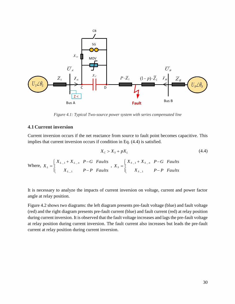
Figure 4.1: Typical Two-source power system with series compensated line
4.1 Current inversion
Current inversion occurs if the net reactance from source to fault point becomes capacitive. This
implies that current inversion occurs if condition in Eq. (4.4) is satisfied.
LSC pXXX (4.4)
Where, Faults
Faults
P
G
P
P
X
XXX
L
nLL
L
1_
_1_
, Faults
Faults
P
G
P
P
X
XXX
S
nSS
S
1_
_1_
It is necessary to analyze the impacts of current inversion on voltage, current and power factor
angle at relay position.
Figure 4.2 shows two diagrams: the left diagram presents pre-fault voltage (blue) and fault voltage
(red) and the right diagram presents pre-fault current (blue) and fault current (red) at relay position
during current inversion. It is observed that the fault voltage increases and lags the pre-fault voltage
at relay position during current inversion. The fault current also increases but leads the pre-fault
current at relay position during current inversion.
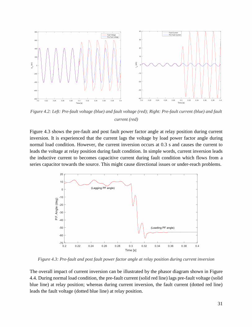
31
Figure 4.2: Left: Pre-fault voltage (blue) and fault voltage (red); Right: Pre-fault current (blue) and fault
current (red)
Figure 4.3 shows the pre-fault and post fault power factor angle at relay position during current
inversion. It is experienced that the current lags the voltage by load power factor angle during
normal load condition. However, the current inversion occurs at 0.3 s and causes the current to
leads the voltage at relay position during fault condition. In simple words, current inversion leads
the inductive current to becomes capacitive current during fault condition which flows from a
series capacitor towards the source. This might cause directional issues or under-reach problems.
Figure 4.3: Pre-fault and post fault power factor angle at relay position during current inversion
The overall impact of current inversion can be illustrated by the phasor diagram shown in Figure
4.4. During normal load condition, the pre-fault current (solid red line) lags pre-fault voltage (solid
blue line) at relay position; whereas during current inversion, the fault current (dotted red line)
leads the fault voltage (dotted blue line) at relay position.

32
Figure 4.4: Phasor diagram of voltage (blue) and current (red) at relay position
4.1.1 Impacts of current inversion on conventional distance relay:
The capacitive current during current inversion causes the reactive power to flow in reverse
direction. The positive active power and reversed reactive power shifts the locus of line impedance
from 1st quadrant into 4th quadrant. Figure 4.5 shows the locus of line impedance during current
inversion for the phase-to-ground impedance fault ( 30fR ) at terminal of a series capacitor in
typical two-source power system with 50% series compensated line and positive sequence source
impedance is ( 51_ SZ ). This leads the conventional distance relay to encounters steady-state
under-reach problems as shown in Figure 4.5. A new distance protection algorithm is thus required
to handle such issues and provide adequate protection to the series compensated line during current
inversion.
33
Figure 4.5: Impacts of current inversion on conventional distance relay
4.2 Voltage inversion
Voltage inversion occurs if the reactance from relay position to fault point becomes capacitive but
the net reactance from source to fault point but is still inductive. Voltage inversion occurs if both
conditions in Eq. (4.5) are satisfied depending upon the location of VT.
LSC
LC
pXXX
pXX (4.5)
Voltage inversion is always associated with SC and it can occur both in strong and weak grid.
It is necessary to analyze the impacts of voltage inversion on voltage, current and power factor
angle at relay position.
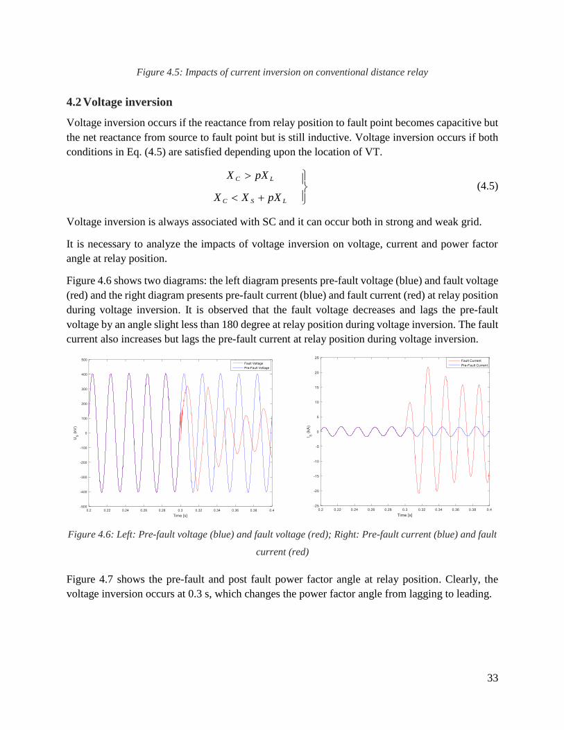
Figure 4.6 shows two diagrams: the left diagram presents pre-fault voltage (blue) and fault voltage
(red) and the right diagram presents pre-fault current (blue) and fault current (red) at relay position
during voltage inversion. It is observed that the fault voltage decreases and lags the pre-fault
voltage by an angle slight less than 180 degree at relay position during voltage inversion. The fault
current also increases but lags the pre-fault current at relay position during voltage inversion.
Figure 4.6: Left: Pre-fault voltage (blue) and fault voltage (red); Right: Pre-fault current (blue) and fault
current (red)
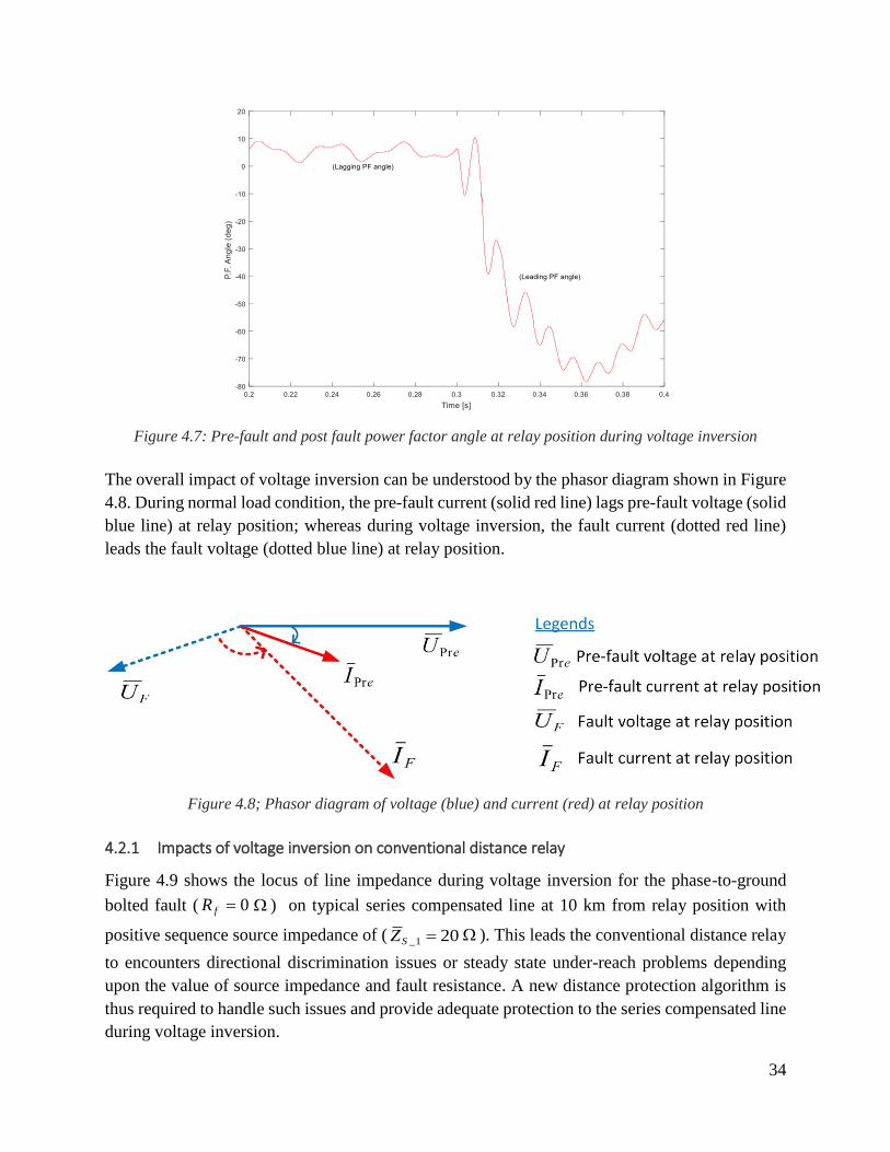
Figure 4.7 shows the pre-fault and post fault power factor angle at relay position. Clearly, the
voltage inversion occurs at 0.3 s, which changes the power factor angle from lagging to leading.
34
Figure 4.7: Pre-fault and post fault power factor angle at relay position during voltage inversion
The overall impact of voltage inversion can be understood by the phasor diagram shown in Figure
4.8. During normal load condition, the pre-fault current (solid red line) lags pre-fault voltage (solid
blue line) at relay position; whereas during voltage inversion, the fault current (dotted red line)
leads the fault voltage (dotted blue line) at relay position.
Figure 4.8; Phasor diagram of voltage (blue) and current (red) at relay position
4.2.1 Impacts of voltage inversion on conventional distance relay
Figure 4.9 shows the locus of line impedance during voltage inversion for the phase-to-ground
bolted fault ( 0fR ) on typical series compensated line at 10 km from relay position with
positive sequence source impedance of ( 201_ SZ ). This leads the conventional distance relay
to encounters directional discrimination issues or steady state under-reach problems depending
upon the value of source impedance and fault resistance. A new distance protection algorithm is
thus required to handle such issues and provide adequate protection to the series compensated line
during voltage inversion.

35
Figure 4.9: Impacts of voltage inversion on conventional distance relay
4.2.2 Conditions for the voltage inversion
The probability of voltage inversion greatly depends upon the location of VT. If VT is installed
before SC, then both voltage inversion and current inversion cannot occur simultaneously during
forward faults. If VT is installed behind SC, then current inversion causes voltage inversion during
forward faults.
To illustrate it analytically, consider two locations “C” and “D” for VT in the typical two-source
power system as shown in Figure 4.10. The power system is assumed to be lossless.
Figure 4.10: Typical two-source power system with two locations for VT
36
The current through the line during forward fault condition is given by Eq. (4.6).
CLS
SS
XpXXj
UI
(4.6)
As per Eq. (5.6), current inversion occurs if the condition LSC pXXX is satisfied.
4.2.2.1 VT installed at location “C”
The voltage at point “C” during forward fault can be expressed by Eq. (4.7).
SCLC IXpXU (4.7)
As per Eq. (4.7) that the voltage inversion occurs if following conditions are met:
LC pXX
LSC pXXX
It can be concluded that both current and voltage inversion cannot occur simultaneously if VT is
installed before SC.
4.2.2.2 VT installed at location “D”
The voltage at point “D” during forward fault can be expressed by Eq. (4.8).
SLD IpXU (4.8)
As per Eq. (4.8) that the voltage inversion occurs if following condition is met:
LSC pXXX
It can be concluded that both current and voltage inversion occurs simultaneously if VT is installed
behind SC.
This project considers VT at location “C” for forward faults analysis.
4.2.3 Impacts of source impedance on current and voltage inversion
The source impedance determines the strength of source whether strong or weak as well as the
level of fault currents. Strong source means low-source impedance thereby resulting high-current
faults and weak source means high-source impedance thereby resulting low-current faults.
The probability of current inversion is more as compared to the voltage inversion if the feeding
source is strong. This means that during current inversion, the level of fault current is enough to
operates MOV and bypasses SC thereby modifying the characteristic of line from compensated
impedance to uncompensated impedance. However, impedance fault reduces the level of fault
current below the protective level and the series capacitor always remain in the fault loop. Strong
37
feeding source shifts the locus of line impedance slightly to the right during fault conditions. It can
be concluded that current or voltage inversion leads to steady state under-reach problems for
existing distance relays if the feeding source is strong.
The probability of voltage inversion increases with increase in source impedance. During high-
source impedance/ weak source the probability of voltage inversion is maximum while the
probability of current inversion is almost zero. During low-current faults, the fault current mainly
flows through SC. Low current-fault conditions in the weak feeding source modify the line
characteristic in such a way that the line characteristic enters the reverse tripping zone of
conventional distance relay and the relay trips wrongly in reverse zone during the forward faults.
This phenomenon is explained in more detail in the next chapter. In short, voltage inversion leads
to directional discrimination issues for conventional distance relay if the feeding source is weak.
4.3 Sub-Synchronous Oscillation (SSO)
SSO occurs if the net reactance from source to fault point in a series compensated line becomes
inductive. SSO occurs if the condition in Eq. (4.9) is satisfied.
LSC pXXX (4.9)
The integration of the series capacitor in a transmission line sets up series resonant resistive-
inductive-capacitive circuit which introduces signal with natural frequency in power system. The
natural frequency of series resonant circuit can be computed by Eq. (4.10).
LS
Cn
pXX
Xf
LCf
2
1 (4.10)
Where, f is the fundamental frequency of power system (50 Hz in Sweden), and nf is natural
frequency of series resonant circuit.
It can be seen by Eq. (4.10) that a fault on series compensated line introduce high or low frequency
components in power system depending upon the source impedance, degree of series
compensation and location of fault.
If the fault occurs on series compensated line such that LSC pXXX , the series resonant circuit
introduces high frequency components in the power system. If the fault occurs on series
compensated line such that LSC pXXX , the series resonant circuit introduces low frequency
components called subharmonics in the power system. These sub-harmonics superimposes on the
fundamental component of voltage and current phasors and introduce distortion in voltage and
current. Figure 4.11 shows the RMS value of fundamental component of voltage (red) and current
(blue) during SSO for the bolted fault occurring at 0.3 s on typical series compensated line at
remote end (200 km from relay position). Clearly, the SSO creates harmonics and distortions in
current and voltage signal, and leads to an error in the impedance measurement.

38
Figure 4.11: Distortion in voltage (red) and current (blue) during SSO
4.3.1 Impacts of SSO on conventional distance relay
The conventional numerical distance relays use a sliding window based Fast Fourier Transform
(FFT) as filtering technique to extract fundamental frequency component. FFT eliminates DC and
high frequency integer components but cannot remove low frequency components/ sub-harmonics.
Consequently, sub-harmonics in the voltage and current create error in the impedance
measurements and produce signal envelops which results impedance characteristic to follow
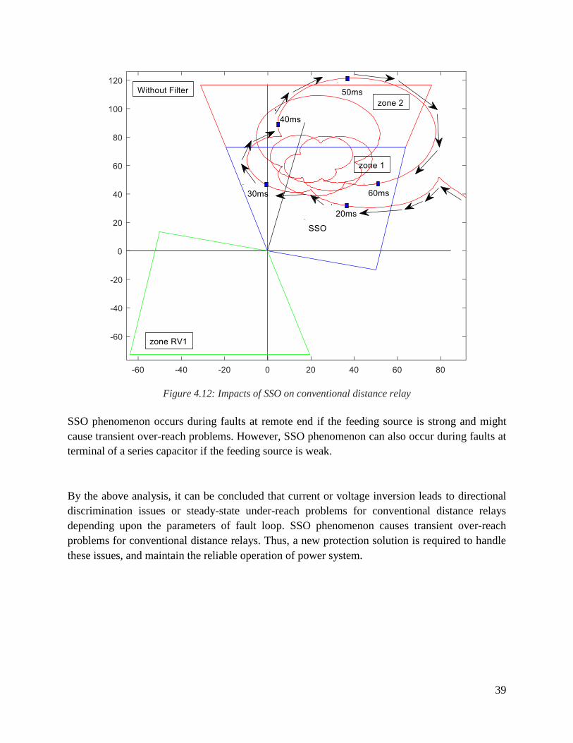
logarithmic spiral during fault conditions. Figure 4.12 shows the impact of SSO on conventional
distance relay during phase-to-ground bolted fault at remote end (200 km from relay position) on
typical series compensated line. It has been seen that conventional distance relay encounters
transient over-reach problems due to the oscillatory spiraling impedance characteristic. This leads
the conventional distance relay to miss-operate in zone 1 for the faults in zone 2 on series
compensated lines. A new mitigation solution is thus required to handle such issues and provide
adequate protection to the faults on series compensated lines during SSO phenomenon.
39
Figure 4.12: Impacts of SSO on conventional distance relay
SSO phenomenon occurs during faults at remote end if the feeding source is strong and might
cause transient over-reach problems. However, SSO phenomenon can also occur during faults at
terminal of a series capacitor if the feeding source is weak.
By the above analysis, it can be concluded that current or voltage inversion leads to directional
discrimination issues or steady-state under-reach problems for conventional distance relays
depending upon the parameters of fault loop. SSO phenomenon causes transient over-reach
problems for conventional distance relays. Thus, a new protection solution is required to handle
these issues, and maintain the reliable operation of power system.

40

41
Chapter 5
Impacts of Series Compensation on Distance Relays
This chapter describes the impacts of SC on the apparent impedance of transmission line. This
chapter also shows how the non-linear MOV modifies the impedance characteristic of line during
fault conditions. This chapter also includes the impacts of SC on the performance of conventional
distance relays. Finally, the chapter is concluded with the problems of SC on distance relays.
5.1 Impacts of a series capacitor on the impedance measurements
Consider a typical two source power system as shown in the Figure 5.1. A series capacitor is
integrated at the beginning of EHV line and the fault occurs on EHV line at P % of total line
impedance from local bus A as shown in the Figure 5.1.
Figure 5.1: Typical two source power system with series compensated EHV line
Where, CX is the capacitive reactance of the series capacitor.
To see the impact of a series capacitor on the apparent impedance of transmission line during
phase-to-ground faults and phase-to-phase faults, we consider phase-to-ground and phase-to-phase
fault loop.
5.1.1 Phase-to- ground fault
During phase-to-ground faults, the power system with a series capacitor can be modelled as
positive, negative and zero sequence network as shown in Figure 5.2.
42
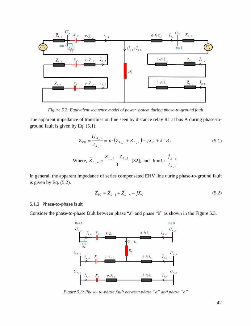
Figure 5.2: Equivalent sequence model of power system during phase-to-ground fault
The apparent impedance of transmission line seen by distance relay R1 at bus A during phase-to-
ground fault is given by Eq. (5.1).
fCnLL
aS
aA
PG RkjXZZpI
UZ _1_
_
_ (5.1)
Where, 3
1_0_
_
LL
nL
ZZZ
[32]; and
aS
aR
I
Ik
_
_1
In general, the apparent impedance of series compensated EHV line during phase-to-ground fault
is given by Eq. (5.2).
CnLLSC jXZZZ _1_ (5.2)
5.1.2 Phase-to-phase fault
Consider the phase-to-phase fault between phase “a” and phase “b” as shown in the Figure 5.3.
Figure 5.3: Phase- to-phase fault between phase “a” and phase “b”
43
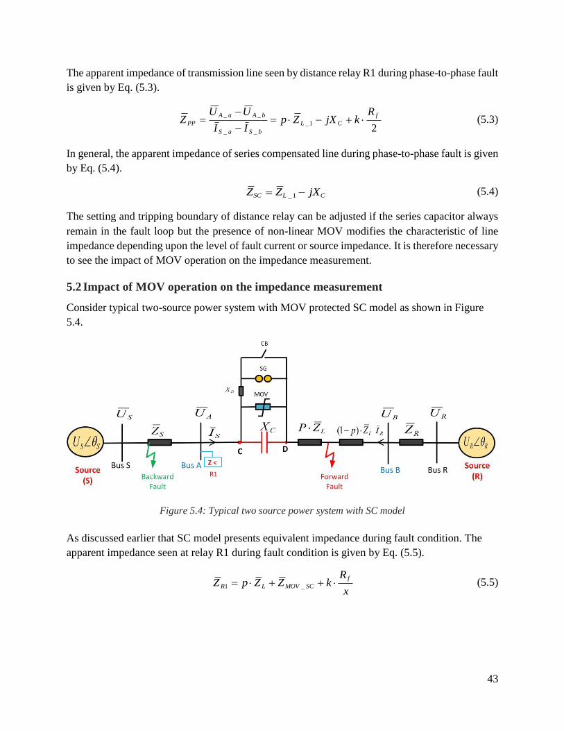
The apparent impedance of transmission line seen by distance relay R1 during phase-to-phase fault
is given by Eq. (5.3).
21_
__
__ f
CL
bSaS
bAaA
PP
RkjXZp
II
UUZ
(5.3)
In general, the apparent impedance of series compensated line during phase-to-phase fault is given
by Eq. (5.4).
CLSC jXZZ 1_ (5.4)
The setting and tripping boundary of distance relay can be adjusted if the series capacitor always
remain in the fault loop but the presence of non-linear MOV modifies the characteristic of line
impedance depending upon the level of fault current or source impedance. It is therefore necessary
to see the impact of MOV operation on the impedance measurement.
5.2 Impact of MOV operation on the impedance measurement
Consider typical two-source power system with MOV protected SC model as shown in Figure
5.4.
Figure 5.4: Typical two source power system with SC model
As discussed earlier that SC model presents equivalent impedance during fault condition. The
apparent impedance seen at relay R1 during fault condition is given by Eq. (5.5).
x
RkZZpZ
f
SCMOVLR _1 (5.5)
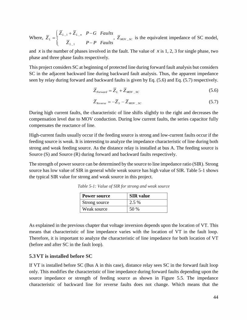
44
Where, Faults
Faults
P
G
P
P
Z
ZZZ
L
nLL
L
1_
_1_
, SCMOVZ _ is the equivalent impedance of SC model,
and x is the number of phases involved in the fault. The value of x is 1, 2, 3 for single phase, two
phase and three phase faults respectively.
This project considers SC at beginning of protected line during forward fault analysis but considers
SC in the adjacent backward line during backward fault analysis. Thus, the apparent impedance
seen by relay during forward and backward faults is given by Eq. (5.6) and Eq. (5.7) respectively.
SCMOVLForward ZZZ _ (5.6)
SCMOVSverse ZZZ _Re (5.7)
During high current faults, the characteristic of line shifts slightly to the right and decreases the
compensation level due to MOV conduction. During low current faults, the series capacitor fully
compensates the reactance of line.
High-current faults usually occur if the feeding source is strong and low-current faults occur if the
feeding source is weak. It is interesting to analyze the impedance characteristic of line during both
strong and weak feeding source. As the distance relay is installed at bus A. The feeding source is
Source (S) and Source (R) during forward and backward faults respectively.
The strength of power source can be determined by the source to line impedance ratio (SIR). Strong
source has low value of SIR in general while weak source has high value of SIR. Table 5-1 shows
the typical SIR value for strong and weak source in this project.
Table 5-1: Value of SIR for strong and weak source
Power source SIR value
Strong source 2.5 %
Weak source 50 %
As explained in the previous chapter that voltage inversion depends upon the location of VT. This
means that characteristic of line impedance varies with the location of VT in the fault loop.
Therefore, it is important to analyze the characteristic of line impedance for both location of VT
(before and after SC in the fault loop).
5.3 VT is installed before SC
If VT is installed before SC (Bus A in this case), distance relay sees SC in the forward fault loop
only. This modifies the characteristic of line impedance during forward faults depending upon the
source impedance or strength of feeding source as shown in Figure 5.5. The impedance
characteristic of backward line for reverse faults does not change. Which means that the
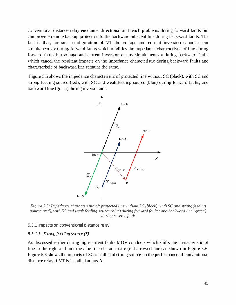
45
conventional distance relay encounter directional and reach problems during forward faults but
can provide remote backup protection to the backward adjacent line during backward faults. The
fact is that, for such configuration of VT the voltage and current inversion cannot occur
simultaneously during forward faults which modifies the impedance characteristic of line during
forward faults but voltage and current inversion occurs simultaneously during backward faults
which cancel the resultant impacts on the impedance characteristic during backward faults and
characteristic of backward line remains the same.
Figure 5.5 shows the impedance characteristic of protected line without SC (black), with SC and
strong feeding source (red), with SC and weak feeding source (blue) during forward faults, and
backward line (green) during reverse fault.
Figure 5.5: Impedance characteristic of: protected line without SC (black), with SC and strong feeding
source (red), with SC and weak feeding source (blue) during forward faults; and backward line (green)
during reverse fault
5.3.1 Impacts on conventional distance relay
5.3.1.1 Strong feeding source (S)
As discussed earlier during high-current faults MOV conducts which shifts the characteristic of
line to the right and modifies the line characteristic (red arrowed line) as shown in Figure 5.6.
Figure 5.6 shows the impacts of SC installed at strong source on the performance of conventional
distance relay if VT is installed at bus A.
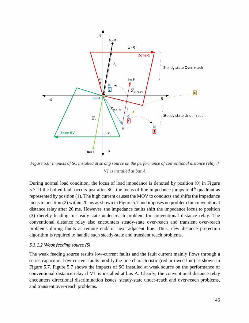
46
Figure 5.6: Impacts of SC installed at strong source on the performance of conventional distance relay if
VT is installed at bus A
During normal load condition, the locus of load impedance is denoted by position (0) in Figure
5.7. If the bolted fault occurs just after SC, the locus of line impedance jumps to 4th quadrant as
represented by position (1). The high current causes the MOV to conducts and shifts the impedance
locus to position (2) within 20 ms as shown in Figure 5.7 and imposes no problem for conventional
distance relay after 20 ms. However, the impedance faults shift the impedance locus to position
(3) thereby leading to steady-state under-reach problem for conventional distance relay. The
conventional distance relay also encounters steady-state over-reach and transient over-reach
problems during faults at remote end/ or next adjacent line. Thus, new distance protection
algorithm is required to handle such steady-state and transient reach problems.
5.3.1.2 Weak feeding source (S)
The weak feeding source results low-current faults and the fault current mainly flows through a
series capacitor. Low-current faults modify the line characteristic (red arrowed line) as shown in
Figure 5.7. Figure 5.7 shows the impacts of SC installed at weak source on the performance of
conventional distance relay if VT is installed at bus A. Clearly, the conventional distance relay
encounters directional discrimination issues, steady-state under-reach and over-reach problems,
and transient over-reach problems.
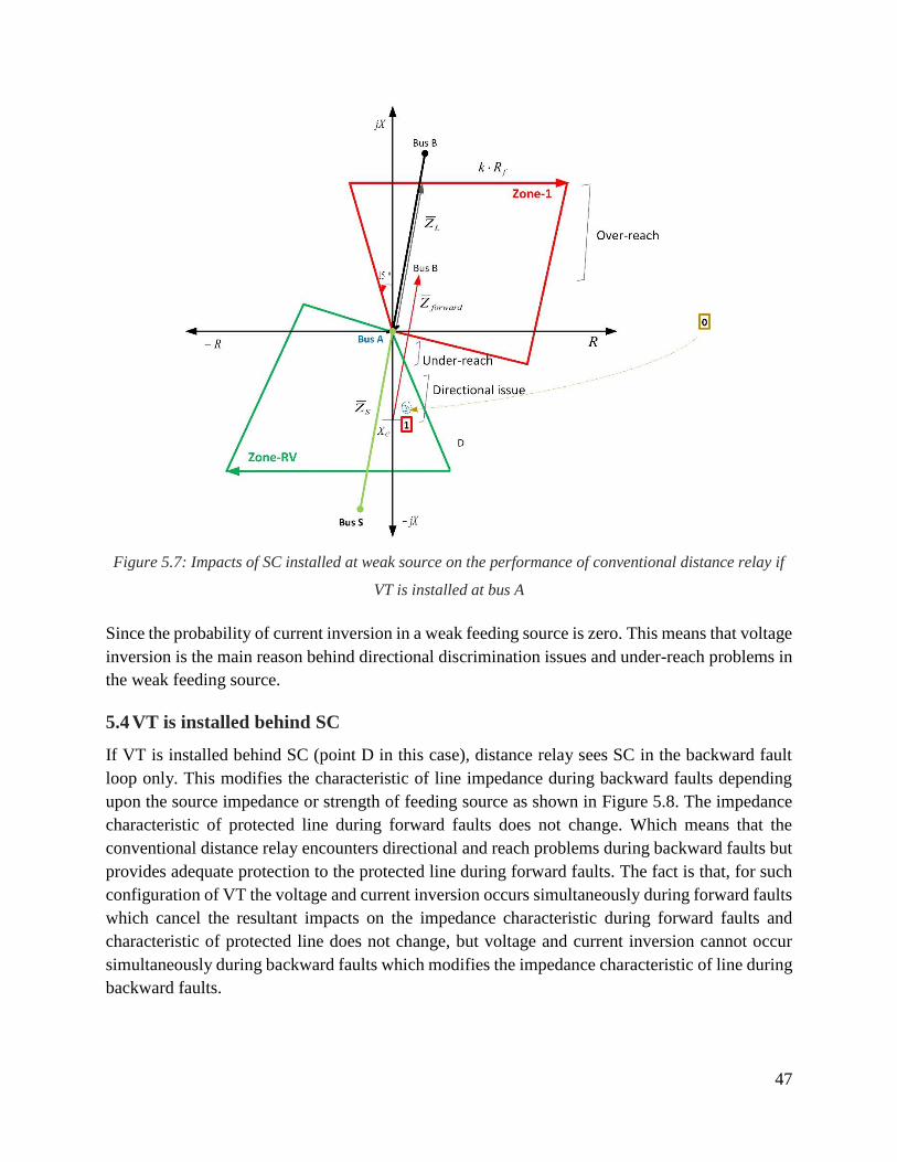
47
Figure 5.7: Impacts of SC installed at weak source on the performance of conventional distance relay if
VT is installed at bus A
Since the probability of current inversion in a weak feeding source is zero. This means that voltage
inversion is the main reason behind directional discrimination issues and under-reach problems in
the weak feeding source.
5.4 VT is installed behind SC
If VT is installed behind SC (point D in this case), distance relay sees SC in the backward fault
loop only. This modifies the characteristic of line impedance during backward faults depending
upon the source impedance or strength of feeding source as shown in Figure 5.8. The impedance
characteristic of protected line during forward faults does not change. Which means that the
conventional distance relay encounters directional and reach problems during backward faults but
provides adequate protection to the protected line during forward faults. The fact is that, for such
configuration of VT the voltage and current inversion occurs simultaneously during forward faults
which cancel the resultant impacts on the impedance characteristic during forward faults and
characteristic of protected line does not change, but voltage and current inversion cannot occur
simultaneously during backward faults which modifies the impedance characteristic of line during
backward faults.

48
Figure 5.8 shows the impedance characteristic of: protected line (black) during forward faults,
backward line without SC (green), with SC and strong feeding source (red), and with SC and weak
feeding source (blue) during reverse faults.
Figure 5.8: Impedance characteristic of: protected line (black) during forward faults, backward line
without SC (green), with SC and strong feeding source (red), and with SC and weak feeding source (blue)
during reverse faults.
5.4.1 Impacts on conventional distance relay
5.4.1.1 Strong feeding source (S)
As discussed earlier that VT is installed at point “D” then distance relay sees SC in the backward
fault loop only which modifies the characteristic of backward line but the characteristic of
protected line remains the same. In this case the impacts of SC on the performance of conventional
distance relay is same as described in the previous section but in opposite direction i.e. the relay
encounters steady-state under-reach and over-reach problems, and transient over-reach problems
during backward faults as shown in Figure 5.9.
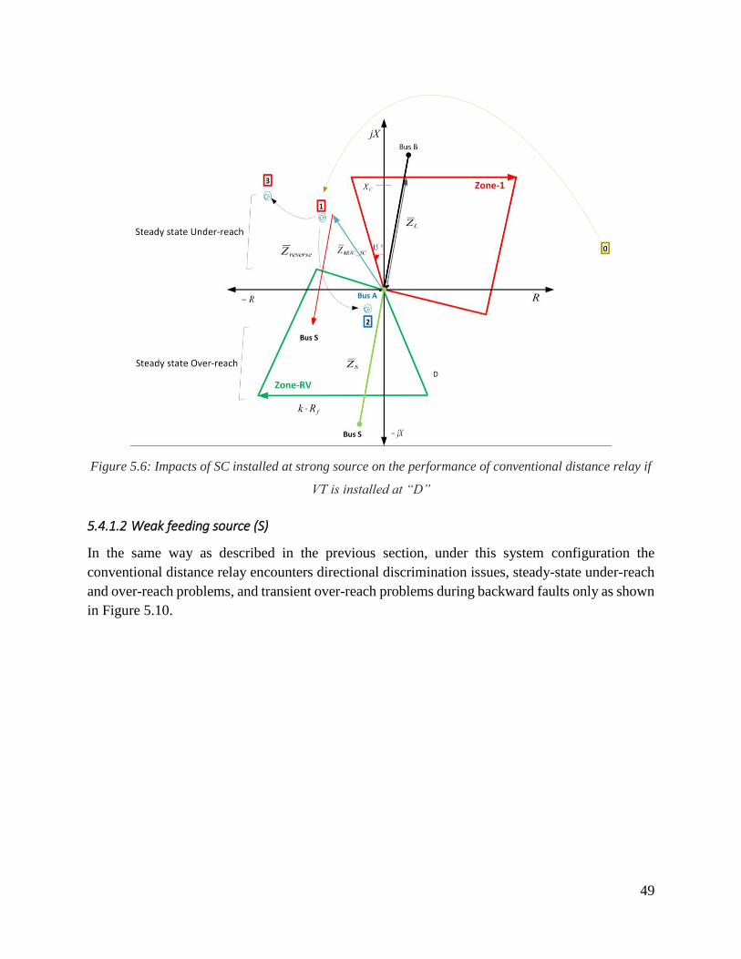
49
Figure 5.6: Impacts of SC installed at strong source on the performance of conventional distance relay if
VT is installed at “D”
5.4.1.2 Weak feeding source (S)
In the same way as described in the previous section, under this system configuration the
conventional distance relay encounters directional discrimination issues, steady-state under-reach
and over-reach problems, and transient over-reach problems during backward faults only as shown
in Figure 5.10.
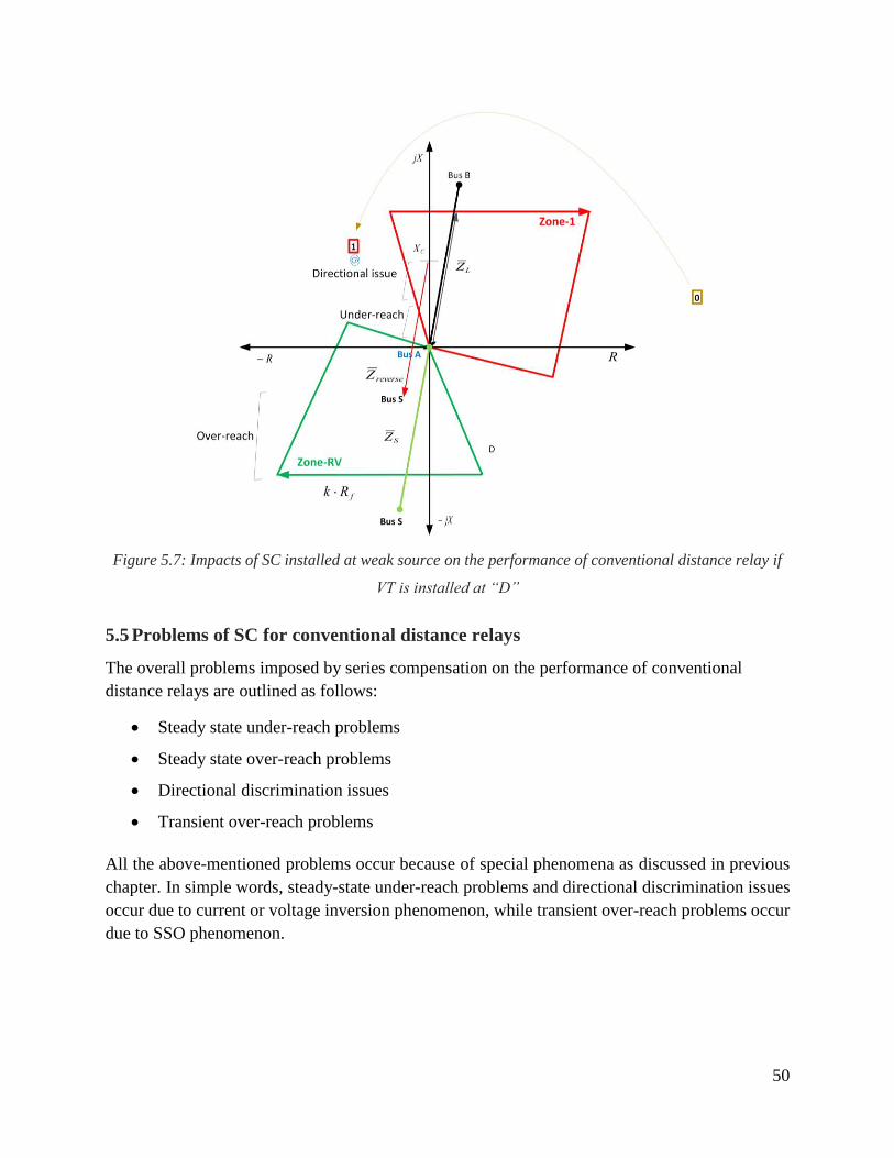
50
Figure 5.7: Impacts of SC installed at weak source on the performance of conventional distance relay if
VT is installed at “D”
5.5 Problems of SC for conventional distance relays
The overall problems imposed by series compensation on the performance of conventional
distance relays are outlined as follows:
Steady state under-reach problems
Steady state over-reach problems
Directional discrimination issues
Transient over-reach problems
All the above-mentioned problems occur because of special phenomena as discussed in previous
chapter. In simple words, steady-state under-reach problems and directional discrimination issues
occur due to current or voltage inversion phenomenon, while transient over-reach problems occur
due to SSO phenomenon.
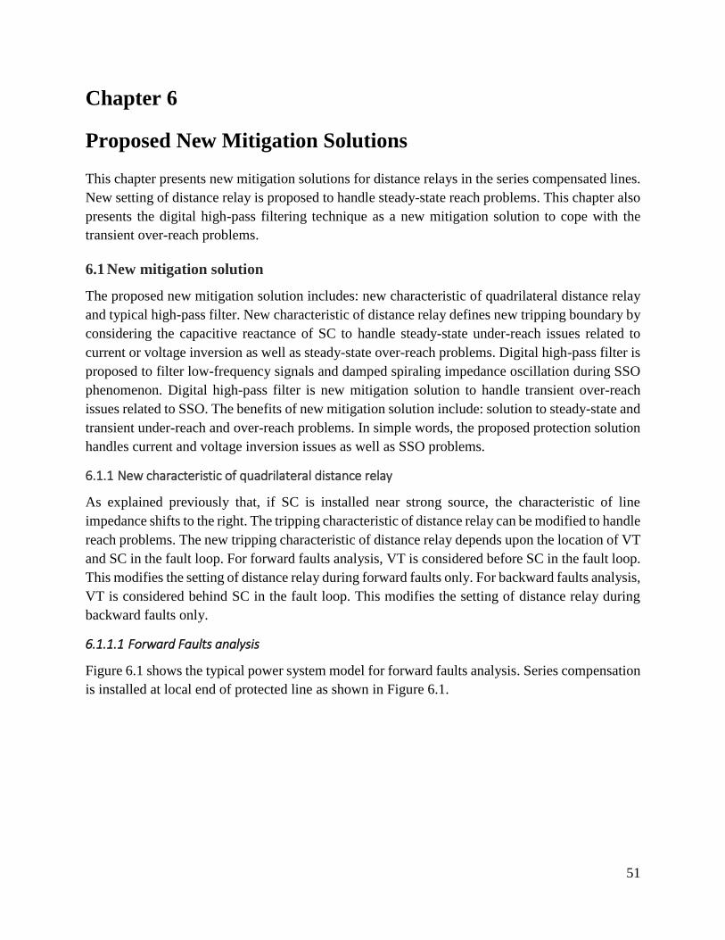
51
Chapter 6
Proposed New Mitigation Solutions
This chapter presents new mitigation solutions for distance relays in the series compensated lines.
New setting of distance relay is proposed to handle steady-state reach problems. This chapter also
presents the digital high-pass filtering technique as a new mitigation solution to cope with the
transient over-reach problems.
6.1 New mitigation solution
The proposed new mitigation solution includes: new characteristic of quadrilateral distance relay
and typical high-pass filter. New characteristic of distance relay defines new tripping boundary by
considering the capacitive reactance of SC to handle steady-state under-reach issues related to
current or voltage inversion as well as steady-state over-reach problems. Digital high-pass filter is
proposed to filter low-frequency signals and damped spiraling impedance oscillation during SSO
phenomenon. Digital high-pass filter is new mitigation solution to handle transient over-reach
issues related to SSO. The benefits of new mitigation solution include: solution to steady-state and
transient under-reach and over-reach problems. In simple words, the proposed protection solution
handles current and voltage inversion issues as well as SSO problems.
6.1.1 New characteristic of quadrilateral distance relay
As explained previously that, if SC is installed near strong source, the characteristic of line
impedance shifts to the right. The tripping characteristic of distance relay can be modified to handle
reach problems. The new tripping characteristic of distance relay depends upon the location of VT
and SC in the fault loop. For forward faults analysis, VT is considered before SC in the fault loop.
This modifies the setting of distance relay during forward faults only. For backward faults analysis,
VT is considered behind SC in the fault loop. This modifies the setting of distance relay during
backward faults only.
6.1.1.1 Forward Faults analysis
Figure 6.1 shows the typical power system model for forward faults analysis. Series compensation
is installed at local end of protected line as shown in Figure 6.1.
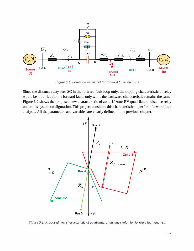
52
Figure 6.1: Power system model for forward faults analysis
Since the distance relay sees SC in the forward fault loop only, the tripping characteristic of relay
would be modified for the forward faults only while the backward characteristic remains the same.
Figure 6.2 shows the proposed new characteristic of zone-1/ zone-RV quadrilateral distance relay
under this system configuration. This project considers this characteristic to perform forward fault
analysis. All the parameters and variables are clearly defined in the previous chapter.
Figure 6.2: Proposed new characteristic of quadrilateral distance relay for forward fault analysis
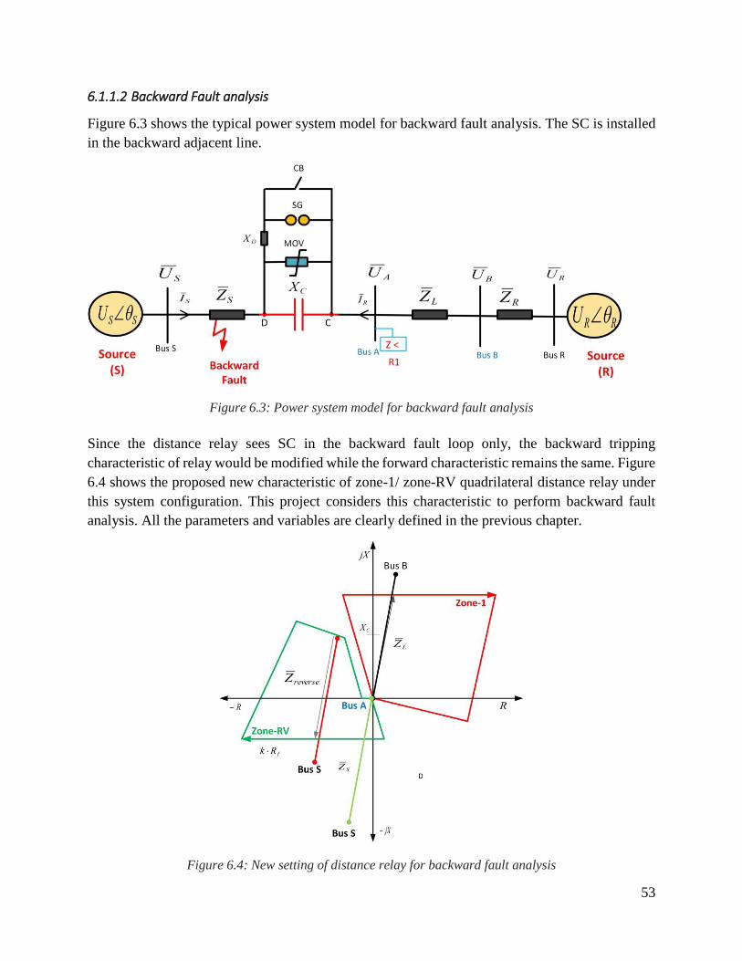
53
6.1.1.2 Backward Fault analysis
Figure 6.3 shows the typical power system model for backward fault analysis. The SC is installed
in the backward adjacent line.
Figure 6.3: Power system model for backward fault analysis
Since the distance relay sees SC in the backward fault loop only, the backward tripping
characteristic of relay would be modified while the forward characteristic remains the same. Figure
6.4 shows the proposed new characteristic of zone-1/ zone-RV quadrilateral distance relay under
this system configuration. This project considers this characteristic to perform backward fault
analysis. All the parameters and variables are clearly defined in the previous chapter.
Figure 6.4: New setting of distance relay for backward fault analysis
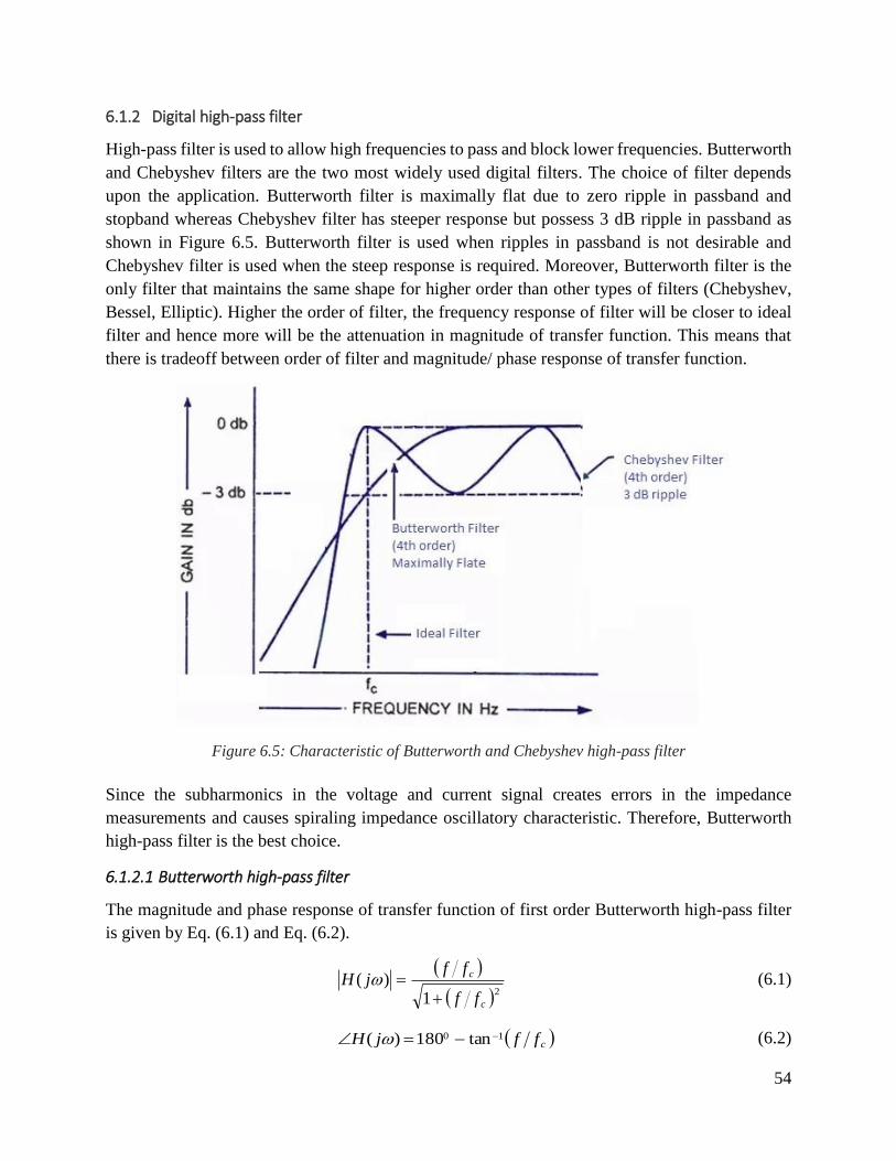
54
6.1.2 Digital high-pass filter
High-pass filter is used to allow high frequencies to pass and block lower frequencies. Butterworth
and Chebyshev filters are the two most widely used digital filters. The choice of filter depends
upon the application. Butterworth filter is maximally flat due to zero ripple in passband and
stopband whereas Chebyshev filter has steeper response but possess 3 dB ripple in passband as
shown in Figure 6.5. Butterworth filter is used when ripples in passband is not desirable and
Chebyshev filter is used when the steep response is required. Moreover, Butterworth filter is the
only filter that maintains the same shape for higher order than other types of filters (Chebyshev,
Bessel, Elliptic). Higher the order of filter, the frequency response of filter will be closer to ideal
filter and hence more will be the attenuation in magnitude of transfer function. This means that
there is tradeoff between order of filter and magnitude/ phase response of transfer function.
Figure 6.5: Characteristic of Butterworth and Chebyshev high-pass filter
Since the subharmonics in the voltage and current signal creates errors in the impedance
measurements and causes spiraling impedance oscillatory characteristic. Therefore, Butterworth
high-pass filter is the best choice.
6.1.2.1 Butterworth high-pass filter
The magnitude and phase response of transfer function of first order Butterworth high-pass filter
is given by Eq. (6.1) and Eq. (6.2).
21
)(
c
c
ff
ffjH
(6.1)
cffjH 10 tan180)( (6.2)
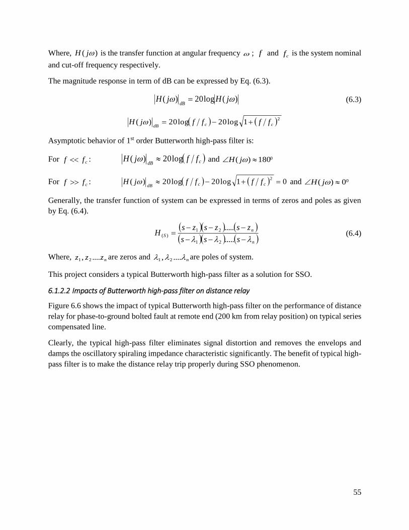
55
Where, )( jH is the transfer function at angular frequency ; f and cf is the system nominal
and cut-off frequency respectively.
The magnitude response in term of dB can be expressed by Eq. (6.3).
)(log20)( jHjHdB (6.3)
21log20log20)( ccdB
ffffjH
Asymptotic behavior of 1st order Butterworth high-pass filter is:
For cff : cdBffjH log20)( and 0180)( jH
For cff : 01log20log20)(2 ccdB
ffffjH and 00)( jH
Generally, the transfer function of system can be expressed in terms of zeros and poles as given
by Eq. (6.4).
n
nS
sss
zszszsH
.....
.....
21
21)( (6.4)
Where, nzzz ...., 21 are zeros and n ...., 21 are poles of system.
This project considers a typical Butterworth high-pass filter as a solution for SSO.
6.1.2.2 Impacts of Butterworth high-pass filter on distance relay
Figure 6.6 shows the impact of typical Butterworth high-pass filter on the performance of distance
relay for phase-to-ground bolted fault at remote end (200 km from relay position) on typical series
compensated line.
Clearly, the typical high-pass filter eliminates signal distortion and removes the envelops and
damps the oscillatory spiraling impedance characteristic significantly. The benefit of typical high-
pass filter is to make the distance relay trip properly during SSO phenomenon.

56
Figure 6.6: Impact of typical Butterworth high-pass filter on the performance of distance relay during
SSO
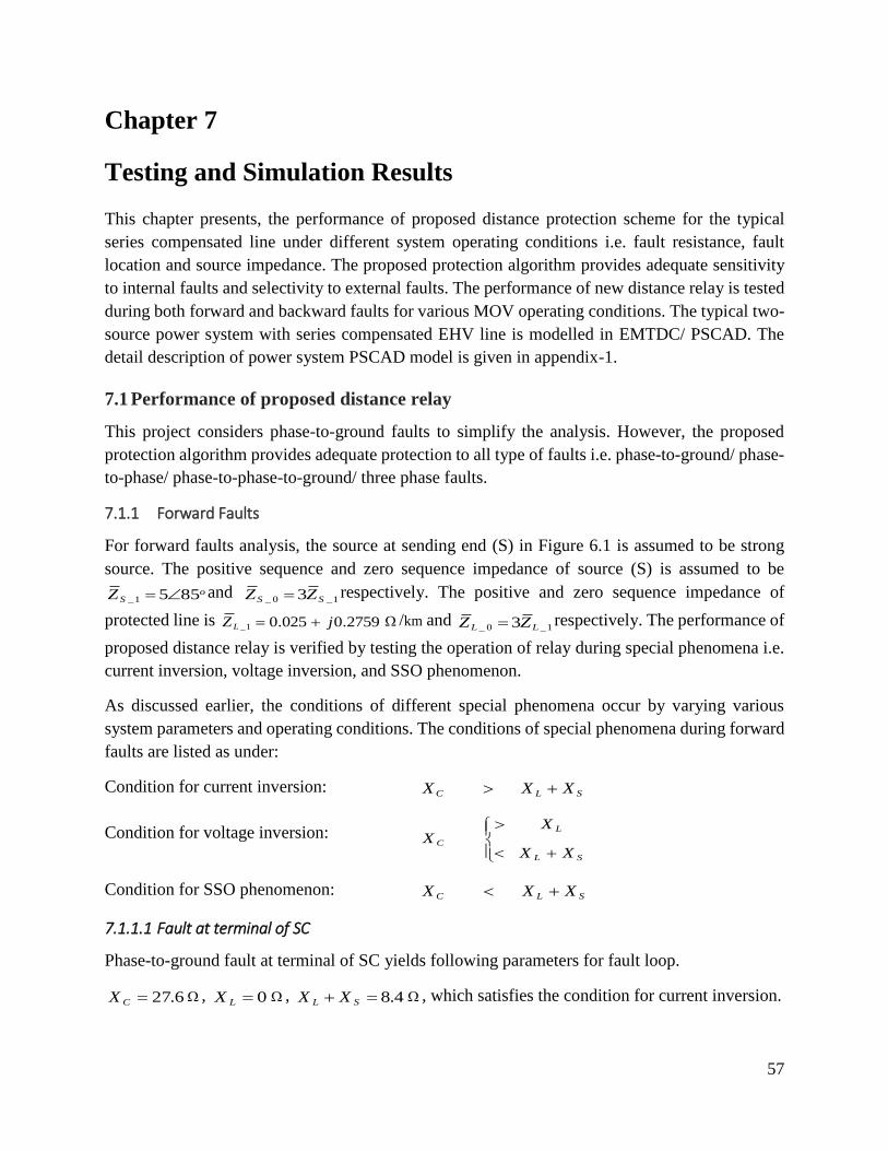
57
Chapter 7
Testing and Simulation Results
This chapter presents, the performance of proposed distance protection scheme for the typical
series compensated line under different system operating conditions i.e. fault resistance, fault
location and source impedance. The proposed protection algorithm provides adequate sensitivity
to internal faults and selectivity to external faults. The performance of new distance relay is tested
during both forward and backward faults for various MOV operating conditions. The typical two-
source power system with series compensated EHV line is modelled in EMTDC/ PSCAD. The
detail description of power system PSCAD model is given in appendix-1.
7.1 Performance of proposed distance relay
This project considers phase-to-ground faults to simplify the analysis. However, the proposed
protection algorithm provides adequate protection to all type of faults i.e. phase-to-ground/ phase-
to-phase/ phase-to-phase-to-ground/ three phase faults.
7.1.1 Forward Faults
For forward faults analysis, the source at sending end (S) in Figure 6.1 is assumed to be strong
source. The positive sequence and zero sequence impedance of source (S) is assumed to be
oSZ 8551_ and
1_0_ 3 SS ZZ respectively. The positive and zero sequence impedance of
protected line is 2759.0025.01_ jZL /km and 1_0_ 3 LL ZZ respectively. The performance of
proposed distance relay is verified by testing the operation of relay during special phenomena i.e.
current inversion, voltage inversion, and SSO phenomenon.
As discussed earlier, the conditions of different special phenomena occur by varying various
system parameters and operating conditions. The conditions of special phenomena during forward
faults are listed as under:
Condition for current inversion: SLC XXX
Condition for voltage inversion:
SL
L
C
XX
XX
Condition for SSO phenomenon: SLC XXX
7.1.1.1 Fault at terminal of SC
Phase-to-ground fault at terminal of SC yields following parameters for fault loop.
6.27CX , 0LX , 4.8 SL XX , which satisfies the condition for current inversion.

58
Figure 7.1 and Figure 7.2 shows the performance of new distance relay for bolted fault i.e. 0fR
and impedance fault i.e. 30fR respectively at terminal of SC. The MOV operates during
bolted faults and the locus of line impedance shifts from 4th quadrant to 1st quadrant within 20 ms
as shown in Figure 7.1. However, the impedance fault reduces fault current below protective level
of current and fault current mainly flows through a series capacitor and the locus of line impedance
lies in 4th quadrant as shown in Figure 7.2. Thus, the proposed distance relay provides adequate
protection during current inversion phenomenon.
Figure 7.1: Performance of distance relay during current inversion for bolted fault at terminal of SC
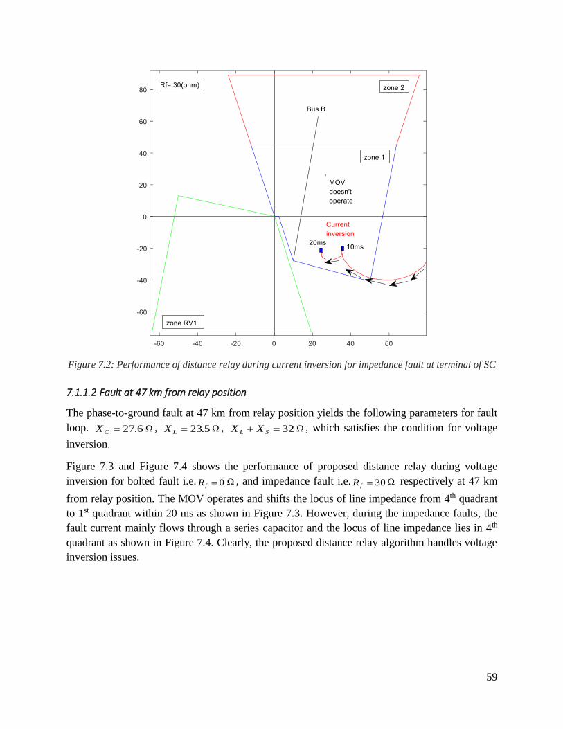
59
Figure 7.2: Performance of distance relay during current inversion for impedance fault at terminal of SC
7.1.1.2 Fault at 47 km from relay position
The phase-to-ground fault at 47 km from relay position yields the following parameters for fault
loop. 6.27CX , 5.23LX , 32 SL XX , which satisfies the condition for voltage
inversion.
Figure 7.3 and Figure 7.4 shows the performance of proposed distance relay during voltage
inversion for bolted fault i.e. 0fR , and impedance fault i.e. 30fR respectively at 47 km
from relay position. The MOV operates and shifts the locus of line impedance from 4th quadrant
to 1st quadrant within 20 ms as shown in Figure 7.3. However, during the impedance faults, the
fault current mainly flows through a series capacitor and the locus of line impedance lies in 4th
quadrant as shown in Figure 7.4. Clearly, the proposed distance relay algorithm handles voltage
inversion issues.
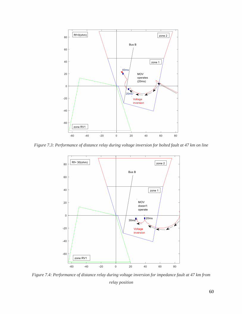
60
Figure 7.3: Performance of distance relay during voltage inversion for bolted fault at 47 km on line
Figure 7.4: Performance of distance relay during voltage inversion for impedance fault at 47 km from
relay position
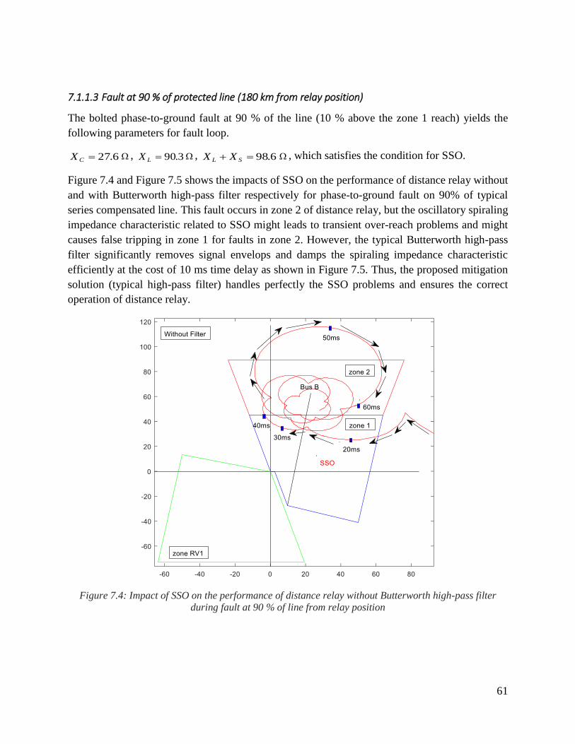
61
7.1.1.3 Fault at 90 % of protected line (180 km from relay position)
The bolted phase-to-ground fault at 90 % of the line (10 % above the zone 1 reach) yields the
following parameters for fault loop.
6.27CX , 3.90LX , 6.98 SL XX , which satisfies the condition for SSO.
Figure 7.4 and Figure 7.5 shows the impacts of SSO on the performance of distance relay without
and with Butterworth high-pass filter respectively for phase-to-ground fault on 90% of typical
series compensated line. This fault occurs in zone 2 of distance relay, but the oscillatory spiraling
impedance characteristic related to SSO might leads to transient over-reach problems and might
causes false tripping in zone 1 for faults in zone 2. However, the typical Butterworth high-pass
filter significantly removes signal envelops and damps the spiraling impedance characteristic
efficiently at the cost of 10 ms time delay as shown in Figure 7.5. Thus, the proposed mitigation
solution (typical high-pass filter) handles perfectly the SSO problems and ensures the correct
operation of distance relay.
Figure 7.4: Impact of SSO on the performance of distance relay without Butterworth high-pass filter
during fault at 90 % of line from relay position
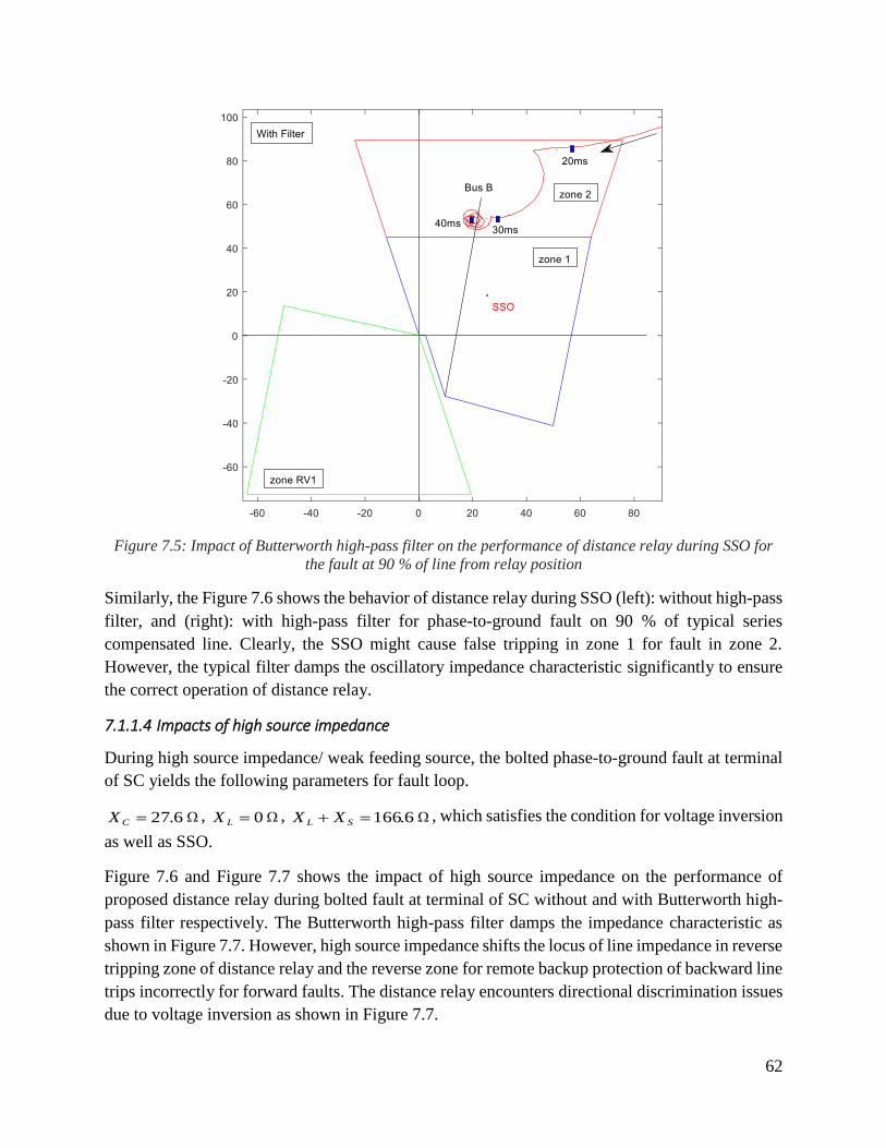
62
Figure 7.5: Impact of Butterworth high-pass filter on the performance of distance relay during SSO for
the fault at 90 % of line from relay position
Similarly, the Figure 7.6 shows the behavior of distance relay during SSO (left): without high-pass
filter, and (right): with high-pass filter for phase-to-ground fault on 90 % of typical series
compensated line. Clearly, the SSO might cause false tripping in zone 1 for fault in zone 2.
However, the typical filter damps the oscillatory impedance characteristic significantly to ensure
the correct operation of distance relay.
7.1.1.4 Impacts of high source impedance
During high source impedance/ weak feeding source, the bolted phase-to-ground fault at terminal
of SC yields the following parameters for fault loop.
6.27CX , 0LX , 6.166 SL XX , which satisfies the condition for voltage inversion
as well as SSO.
Figure 7.6 and Figure 7.7 shows the impact of high source impedance on the performance of
proposed distance relay during bolted fault at terminal of SC without and with Butterworth high-
pass filter respectively. The Butterworth high-pass filter damps the impedance characteristic as
shown in Figure 7.7. However, high source impedance shifts the locus of line impedance in reverse
tripping zone of distance relay and the reverse zone for remote backup protection of backward line
trips incorrectly for forward faults. The distance relay encounters directional discrimination issues
due to voltage inversion as shown in Figure 7.7.
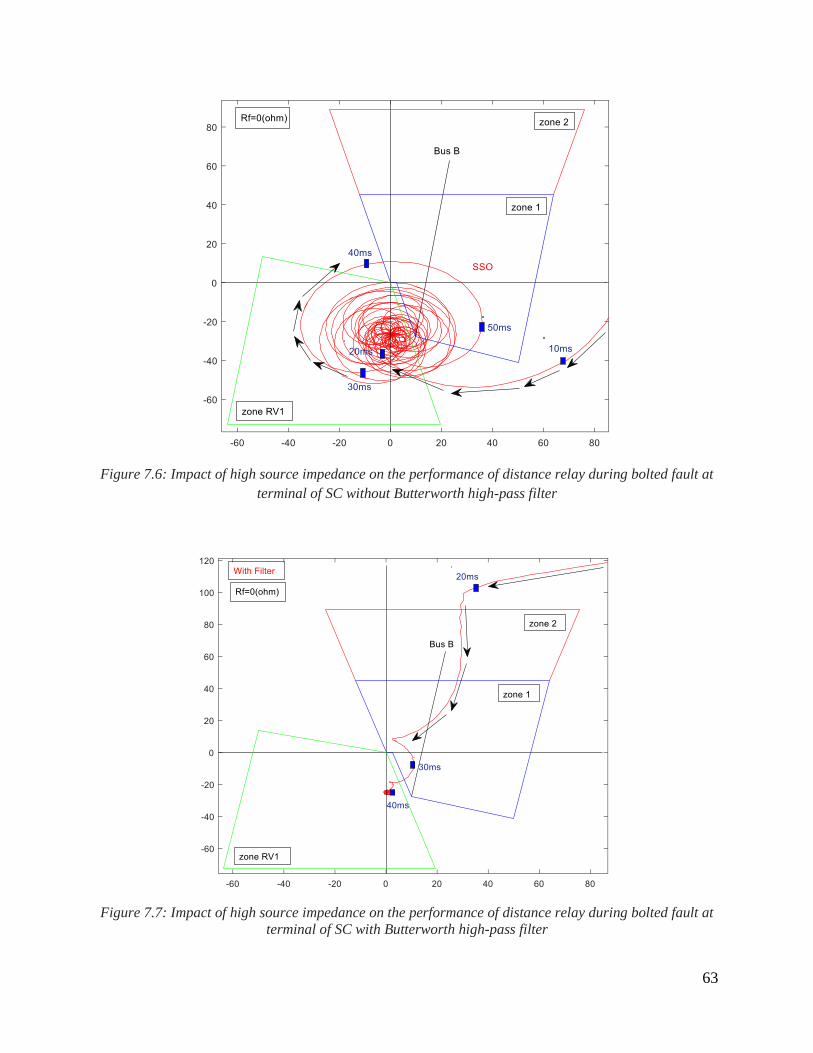
63
Figure 7.6: Impact of high source impedance on the performance of distance relay during bolted fault at
terminal of SC without Butterworth high-pass filter
Figure 7.7: Impact of high source impedance on the performance of distance relay during bolted fault at
terminal of SC with Butterworth high-pass filter
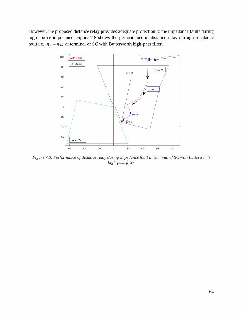
64
However, the proposed distance relay provides adequate protection to the impedance faults during
high source impedance. Figure 7.8 shows the performance of distance relay during impedance
fault i.e. 8fR at terminal of SC with Butterworth high-pass filter.
Figure 7.8: Performance of distance relay during impedance fault at terminal of SC with Butterworth
high-pass filter

65
7.1.2 Backward Faults
For backward faults analysis, the source at receiving end (R) in Figure 6.3 is assumed to be strong
source. The positive sequence and zero sequence impedance of source (R) is assumed to be
oRZ 8551_ and
1_0_ 3 RR ZZ respectively. For backward fault analysis, the following
assumption are made. 01_ LZ , 2759.0025.01_ jZS /km and 1_0_ 3 SS ZZ .
The performance of proposed distance relay is tested during backward faults for special
phenomena i.e. current inversion, voltage inversion, and SSO phenomenon.
The conditions of special phenomena during backward faults are listed as under:
Condition for current inversion: SLRC XXXX
Condition for voltage inversion:
SLR
S
C
XXX
XX
Condition for SSO phenomenon: SLRC XXXX
7.1.2.1 Fault at terminal of SC
Phase-to-ground backward fault at terminal of SC yields following parameters for fault loop.
6.27CX 0SX , 4.8 SLR XXX , which satisfies the condition for current
inversion.
Figure 7.9 shows the performance of distance relay for bolted backward fault i.e. 0fR at
terminal of SC. The MOV operates and shifts the locus of line impedance from 4th quadrant to 1st
quadrant within 20 ms as shown in Figure 7.9.

66
Figure 7.9: Performance of distance relay for bolted backward fault at terminal of SC
7.1.2.2 Backward fault at 40 km from relay position
The phase-to-ground fault at 40 km on backward line from relay position yields the following
parameters for fault loop. 6.27CX , 5.20SX , 4.28 SLR XXX , which satisfies
the condition for voltage inversion.
Figure 7.10 shows the performance of distance relay for bolted fault i.e. 0fR at 40 km on
backward line from relay position. The MOV operates and shifts the locus of line impedance from
4th quadrant to 1st quadrant within 20 ms as shown in Figure 7.10

67
Figure 7.10: Performance of distance relay for bolted backward fault at 40 km from relay position
7.1.2.3 Fault at remote end (200 km on backward line) from relay position
The phase-to-ground fault at remote end (200 km on backward line) from relay position yields the
following parameters for fault loop.
6.27CX , 3.100SX , 4.108 SLR XXX , which satisfies the condition for SSO
phenomenon.
Figure 7.11 and Figure 7.12 shows the impacts of SSO on the performance of distance relay
without and with Butterworth high-pass filter respectively. This fault occurs on the boundary of
zone 1. The spiral impedance characteristic in Figure 7.11 is related to SSO but the typical
Butterworth high-pass filter significantly removes signal envelops and damps the spiraling
impedance characteristic efficiently as shown in Figure 7.12. But since reverse zone acts as remote
backup protection for backward adjacent line so the SSO problem is not a major issue for reverse
zone of distance relay.

68
Figure 7.11: Impact of SSO on the performance of distance relay without Butterworth high-pass filter
during fault at remote end of backward line from relay position
Figure 7.12: Impact of Butterworth high-pass filter on the performance of distance relay during SSO for
fault at remote end of backward line from relay position
69
Chapter 8
Conclusions
This chapter presents the main conclusion of this master degree project, future research and
recommendation of author.
8.1 Main Conclusions
The main objective of this project is to analyze the impacts of SC on the performance of
conventional distance relays and propose a new protection solution to mitigate the shortcomings
of distance protection scheme during faults on the series compensated lines. The overall conclusion
of this project is outlined as follows:
The probability of current inversion is more if SC is installed at strong source and might
cause the conventional distance relay to encounter steady-state under-reach problems
depending upon the fault resistance.
The probability of voltage inversion is more if SC is installed at weak source and might
cause the conventional distance relay to encounter directional discrimination issues or
steady-state under-reach problem depending upon the fault resistance.
SSO occurs if the net reactance of fault loop becomes inductive. SSO occurs at remote end
if the feeding source is strong but can also occurs near SC if the feeding source is weak.
SSO phenomenon in series compensated lines causes the conventional distance relay to
encounter transient over-reach problems especially for zone 1 setting.
Current and voltage inversion cannot occur simultaneously if VT is installed before SC in
the fault loop and vice versa.
The condition of current inversion and SSO contradicts with each other. This means that
both current inversion and SSO cannot occur simultaneously.
SSO can occur together with voltage inversion.
In summary, the integration of SC leads to steady state under-reach and over-reach
problems, directional discrimination issues, and transient over-reach problems for
conventional distance relays. The conventional relays might encounter false tripping or
blinding depending upon the parameters of fault loop.
New quadraliteral characteristic is proposed for distance relays to handle steady-state
under-reach, and over-reach problems.
70
Typical digital high-pass filter is designed and implemented as a new solution to cope with
SSO problems and handle transient over-reach issues.
The directional discrimination issue is still challenging during bolted fault near the series
capacitor if SC is installed at weak source. However, the new relay algorithm provides
adequate protection for impedance faults even if SC is installed at weak source.
8.2 Future research and Recommendation
This project considers SC installed at sending end of protected line. The author of this report put
huge efforts and innovative skills to analyze the impacts of series compensation on the
performance of conventional distance relay in a very good way. The author of this report also
proposed new distance protection solution to handle the protection issues during faults on the series
compensated lines. The proposed protection algorithm detects any type of bolted and impedance
faults (up to 50 ) on series compensated lines within 20 ms. The proposed protection scheme is
found to be advantageous. The author intends to explore further research in the same domain by
analyzing the impacts of series compensation on the behavior of interconnected power system. For
the future research, the author suggests and recommends that it is also necessary to investigate the
impacts of series compensation on the performance of distance relays for the following cases.
SC installed at remote end of the line
SC installed in the parallel lines
SC installed in the adjacent backward and forward lines.
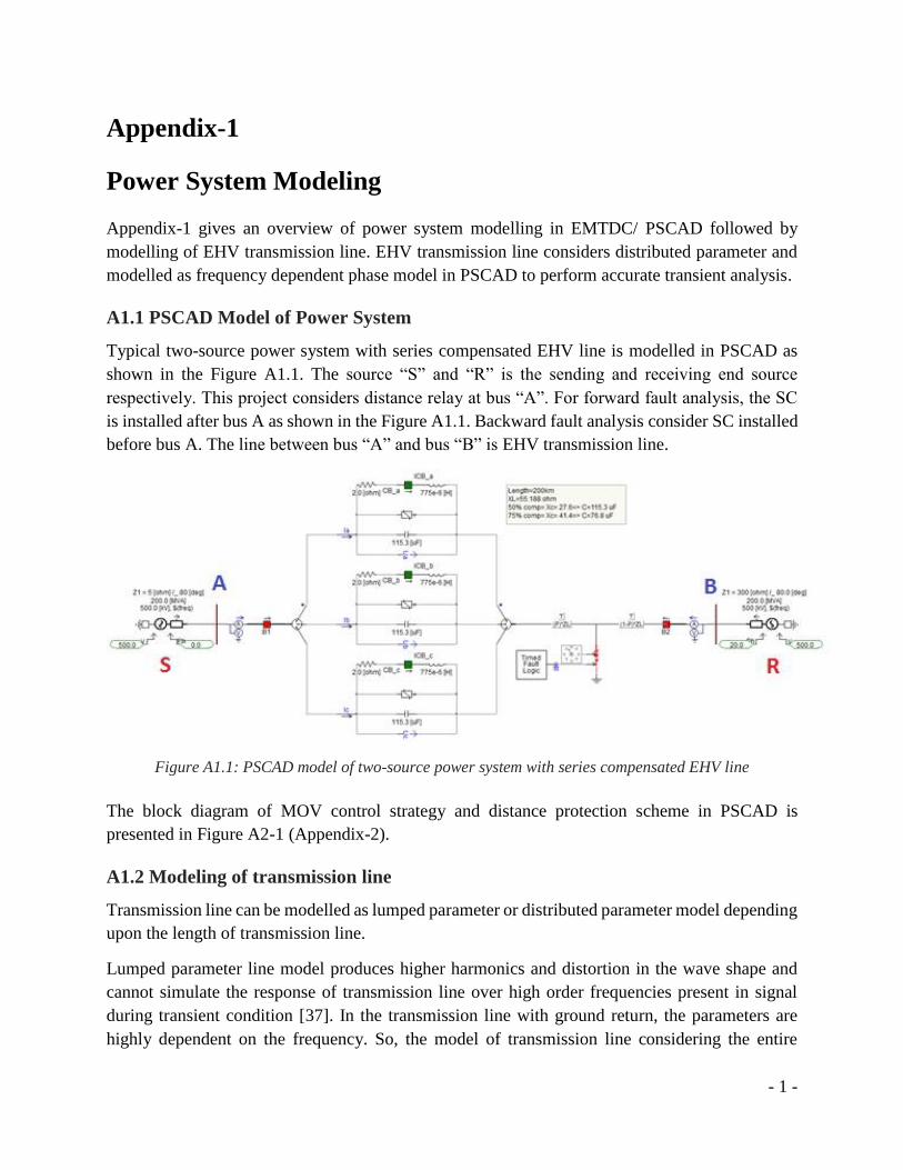
- 1 -
Appendix-1
Power System Modeling
Appendix-1 gives an overview of power system modelling in EMTDC/ PSCAD followed by
modelling of EHV transmission line. EHV transmission line considers distributed parameter and
modelled as frequency dependent phase model in PSCAD to perform accurate transient analysis.
A1.1 PSCAD Model of Power System
Typical two-source power system with series compensated EHV line is modelled in PSCAD as
shown in the Figure A1.1. The source “S” and “R” is the sending and receiving end source
respectively. This project considers distance relay at bus “A”. For forward fault analysis, the SC
is installed after bus A as shown in the Figure A1.1. Backward fault analysis consider SC installed
before bus A. The line between bus “A” and bus “B” is EHV transmission line.
Figure A1.1: PSCAD model of two-source power system with series compensated EHV line
The block diagram of MOV control strategy and distance protection scheme in PSCAD is
presented in Figure A2-1 (Appendix-2).
A1.2 Modeling of transmission line
Transmission line can be modelled as lumped parameter or distributed parameter model depending
upon the length of transmission line.
Lumped parameter line model produces higher harmonics and distortion in the wave shape and
cannot simulate the response of transmission line over high order frequencies present in signal
during transient condition [37]. In the transmission line with ground return, the parameters are
highly dependent on the frequency. So, the model of transmission line considering the entire
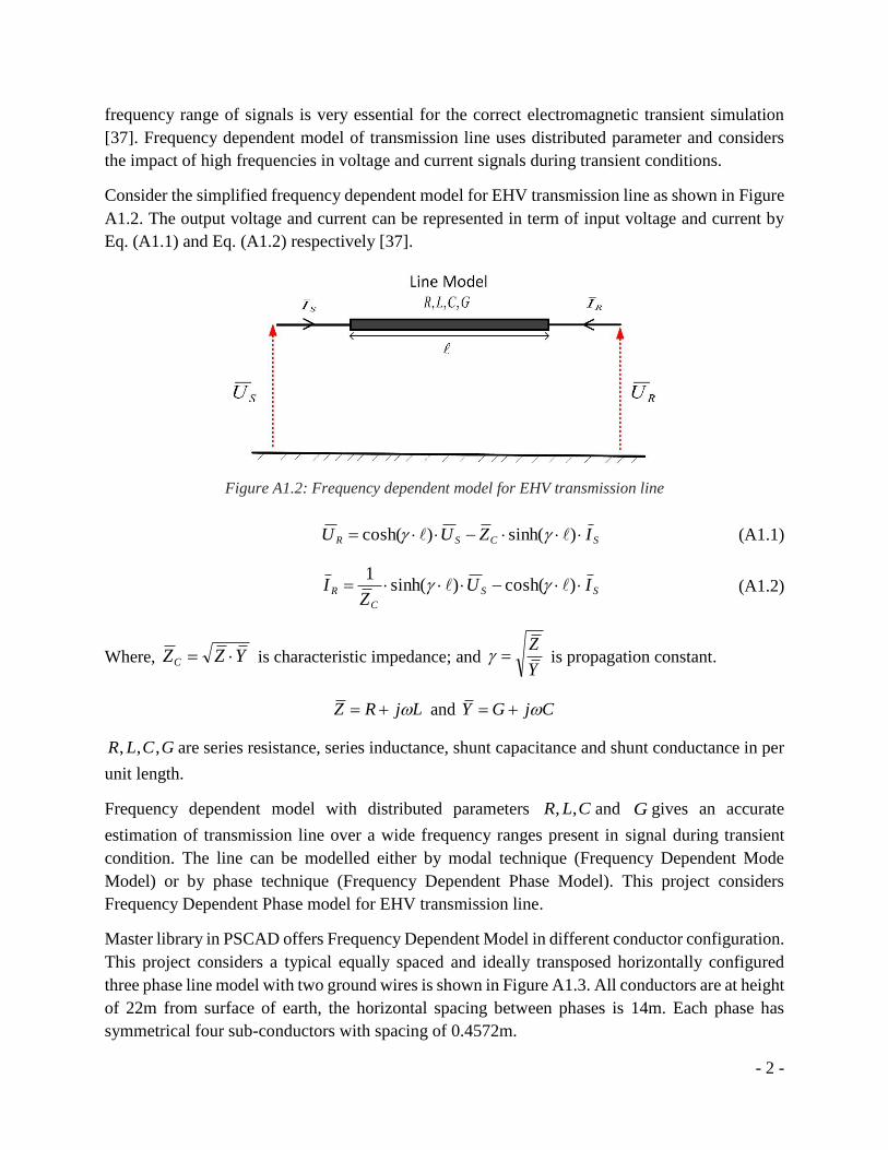
- 2 -
frequency range of signals is very essential for the correct electromagnetic transient simulation
[37]. Frequency dependent model of transmission line uses distributed parameter and considers
the impact of high frequencies in voltage and current signals during transient conditions.
Consider the simplified frequency dependent model for EHV transmission line as shown in Figure
A1.2. The output voltage and current can be represented in term of input voltage and current by
Eq. (A1.1) and Eq. (A1.2) respectively [37].
Figure A1.2: Frequency dependent model for EHV transmission line
SCSR IZUU )sinh()cosh( (A1.1)
SS
C
R IUZ
I )cosh()sinh(1
(A1.2)
Where, YZZC is characteristic impedance; and Y
Z is propagation constant.
LjRZ and CjGY
GCLR ,,, are series resistance, series inductance, shunt capacitance and shunt conductance in per
unit length.
Frequency dependent model with distributed parameters CLR ,, and G gives an accurate
estimation of transmission line over a wide frequency ranges present in signal during transient
condition. The line can be modelled either by modal technique (Frequency Dependent Mode
Model) or by phase technique (Frequency Dependent Phase Model). This project considers
Frequency Dependent Phase model for EHV transmission line.
Master library in PSCAD offers Frequency Dependent Model in different conductor configuration.
This project considers a typical equally spaced and ideally transposed horizontally configured
three phase line model with two ground wires is shown in Figure A1.3. All conductors are at height
of 22m from surface of earth, the horizontal spacing between phases is 14m. Each phase has
symmetrical four sub-conductors with spacing of 0.4572m.
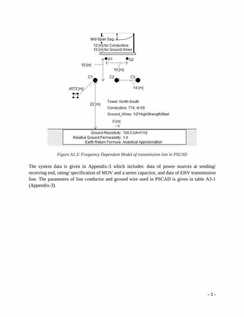
- 3 -
Figure A1.3: Frequency Dependent Model of transmission line in PSCAD
The system data is given in Appendix-3 which includes: data of power sources at sending/
receiving end, rating/ specification of MOV and a series capacitor, and data of EHV transmission
line. The parameters of line conductor and ground wire used in PSCAD is given in table A3-1
(Appendix-3).

- 4 -
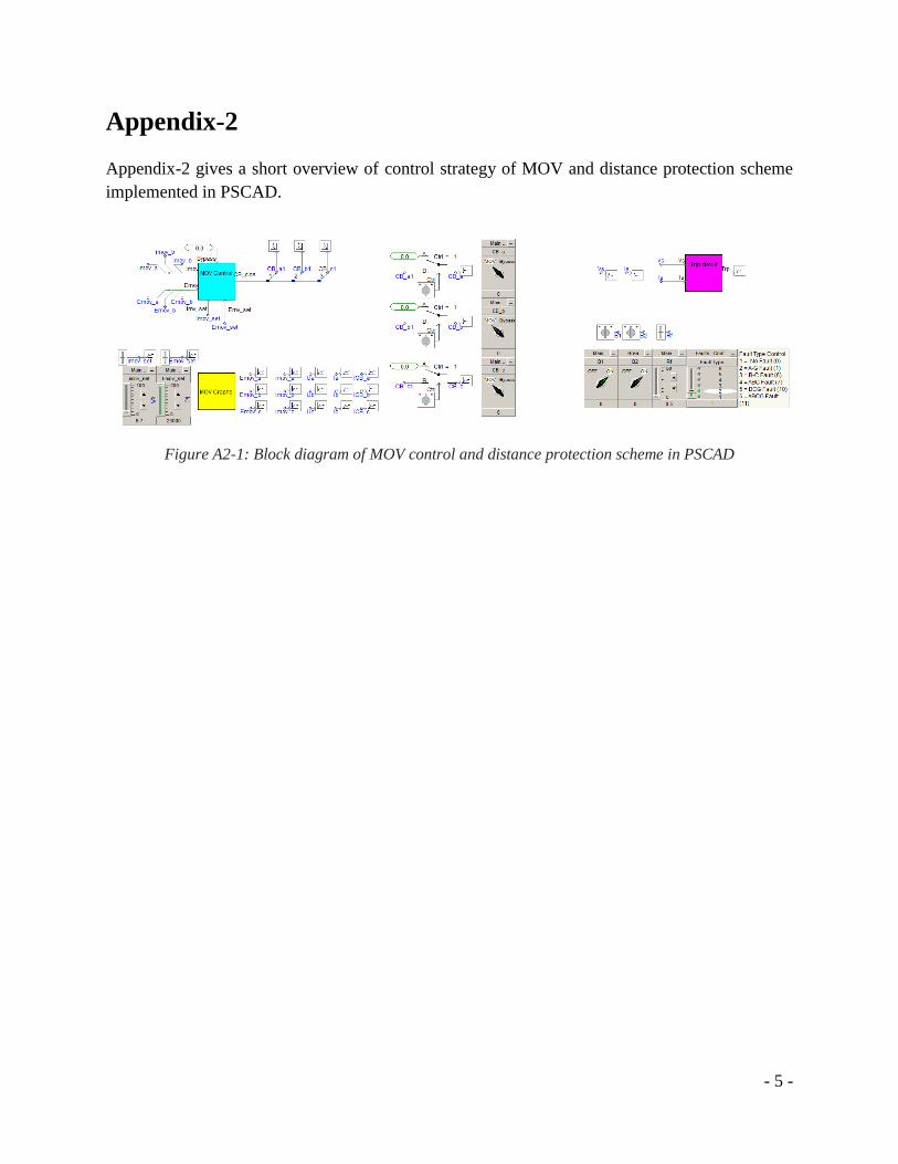
- 5 -
Appendix-2
Appendix-2 gives a short overview of control strategy of MOV and distance protection scheme
implemented in PSCAD.
Figure A2-1: Block diagram of MOV control and distance protection scheme in PSCAD

- 6 -
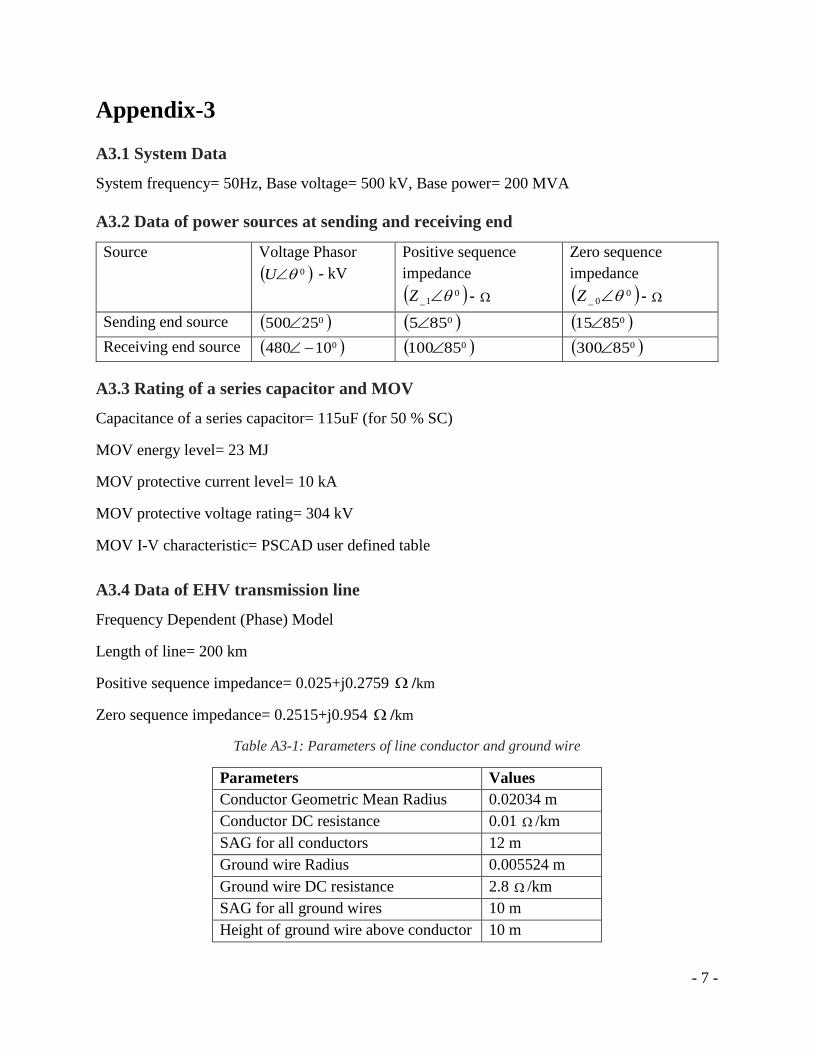
- 7 -
Appendix-3
A3.1 System Data
System frequency= 50Hz, Base voltage= 500 kV, Base power= 200 MVA
A3.2 Data of power sources at sending and receiving end
Source Voltage Phasor
0U - kV
Positive sequence
impedance
01_ Z -
Zero sequence
impedance
00_ Z -
Sending end source 025500 0855 08515
Receiving end source 010480 085100 085300
A3.3 Rating of a series capacitor and MOV
Capacitance of a series capacitor= 115uF (for 50 % SC)
MOV energy level= 23 MJ
MOV protective current level= 10 kA
MOV protective voltage rating= 304 kV
MOV I-V characteristic= PSCAD user defined table
A3.4 Data of EHV transmission line
Frequency Dependent (Phase) Model
Length of line= 200 km
Positive sequence impedance= 0.025+j0.2759 /km
Zero sequence impedance= 0.2515+j0.954 /km
Table A3-1: Parameters of line conductor and ground wire
Parameters Values
Conductor Geometric Mean Radius 0.02034 m
Conductor DC resistance 0.01 /km
SAG for all conductors 12 m
Ground wire Radius 0.005524 m
Ground wire DC resistance 2.8 /km
SAG for all ground wires 10 m
Height of ground wire above conductor 10 m

- 8 -

- 9 -
References
[1] Energy Information Administration (EIA), \International energy outlook 2016," tech. rep., IEA, 6 2016.
[2] Hingorani, Narain G., and Laszlo Gyugyi. Understanding facts. IEEE press, 2000.
[3] Brunello, Gustavo, and Bogdan KASZTENNY. "Distance Protection of Series Compensated Lines Problems and
Solutions." 28 TH Annual Western Protective Relay Conference, Spokane. 2001.
[4] Zellagui, Mohamed, and Abdelaziz Chaghi. "MHO distance relay of transmission line high voltage using series
compensation in Algerian networks." Journal of ACTA Electrotehnica 52.3 (2011): 126-133.
[5] Floriano, C. A. F., et al. "Real time simulation of protections for 500 kV series compensated lines." Transmission
and Distribution Conference and Exposition: Latin America, 2004 IEEE/PES. IEEE, 2004.
[6] Alexander, G. E., et al. "Series Compensated Line Protection: Evaluation & Solutions." GE Power Management,
GER3736 (1998).
[7] Goldsworthy, Daniel L. "A linearized model for MOV-protected series capacitors." IEEE Transactions on Power
Systems 2.4 (1987): 953-957.
[8] Altuve, Héctor J., Joseph B. Mooney, and George E. Alexander. "Advances in series-compensated line
protection." Protective Relay Engineers, 2009 62nd Annual Conference for. IEEE, 2009.
[9] Makwana, Vijay H., and Bhavesh R. Bhalja. "Digital Distance Relaying Scheme for Series-Compensated Parallel
Lines During Simultaneous Open Conductor and Ground Fault." Transmission Line Protection Using Digital
Technology. Springer Singapore, 2016. 89-119
[10] Ziegler, Gerhard. "Numerical Distance Protection Principle and Applications, Berlin and munchen Siemens
Aktiengesellschaft, Ed. Erlangen." (2006).
[11] Calero Fernando and Altuve, Héctor J. " Identifying the Proper Impedance Plane and Fault Trajectories in
Distance Protection Analysis.” 38th Annual Western Protective Relay Conference, Oct. 2011.
[12] Bakie, Eric, et al. "Voltage and current inversion challenges when protecting series-compensated lines—A case
study." Protective Relay Engineers (CPRE), 2016 69th Annual Conference for. IEEE, 2016.
[13] Brunet-Watson, Marc, Jed Leighfield, and PSC North America. "Review of Series Compensation for
Transmission Lines." (2014).
[14] Vyas, Bhargav, Rudra Prakash Maheshwari, and Biswarup Das. "Protection of series compensated transmission
line: issues and state of art." Electric power systems research 107 (2014): 93-108.
[15] Guajardo, LA Trujillo, and A. Conde Enríquez. "Enhanced performance for distance relays due to series
capacitors in transmission lines." Electric Power Systems Research 109 (2014): 20-31.
[16] G. Multilin, D90 Plus Line Distance Protection System Instruction manual. GE Multilin, 2012.
- 10 -
[17] Balcerek, Przemyslaw, et al. "Optimization of distance protection algorithm for double-circuit series-
compensated transmission line." Advanced Power System Automation and Protection (APAP), 2011 International
Conference on. Vol. 2. IEEE, 2011.
[18] Rosolowski, Eugeniusz, et al. "High voltage series-compensated transmission line-evaluation of new distance
protection." High Voltage Engineering and Application (ICHVE), 2010 International Conference on. IEEE, 2010.
[19] Salman, S. K., N. Rajoo, and V. Leittloff. "Investigation of the effect of the insertion of series capacitors in high
voltage transmission lines on the settings of distance protection." (2001): 371-374.
[20] Sivov, Oleg, Hany Abdelsalam, and Elham Makram. "Adaptive setting of distance relay for MOV-protected
series compensated line considering wind power." Electric Power Systems Research 137 (2016): 142-154
[21] Biswal, Monalisa, Bibhuti Bhusan Pati, and Ashok Kumar Pradhan. "Directional relaying of series-compensated
line using an integrated approach." Electric Power Components and Systems 40.7 (2012): 691-710.
[22] Jena, Premalata, and Ashok Kumar Pradhan. "A positive-sequence directional relaying algorithm for series-
compensated line." IEEE Transactions on Power Delivery 25.4 (2010): 2288-2298.
[23] Alexander, George E., Joe Mooney, and William Tyska. "Advanced application guidelines for ground fault
protection." proceedings of the 28th Annual Western Protective Relay Conference, Spokane, WA. 2001.
[24] Hashemi, S. M., M. Tarafdar Hagh, and H. Seyedi. "A novel backup distance protection scheme for series-
compensated transmission lines." IEEE Transactions on Power Delivery 29.2 (2014): 699-707.
[25] Baradar, Mohamadreza, Saeed Afsharnia, and Majid Sanaye-Pasand. "A fast method for fault section
identification in series compensated transmission lines." Environment and Electrical Engineering (EEEIC), 2010 9th
International Conference on. IEEE, 2010.
[26] Solat, Alireza, and Ali Deihimi. "A novel scheme for distance protection of series compensated transmission lines
with TCSC using artificial neural networks." Electrical Engineering (ICEE), 2012 20th Iranian Conference on. IEEE,
2012.
[27] Song, Y. H., A. T. Johns, and Q. Y. Xuan. "Artificial neural-network-based protection scheme for controllable
series-compensated EHV transmission lines." IEE Proceedings-generation, transmission and distribution 143.6
(1996): 535-540.
[28] Pandya, V. J., and S. A. Kanitkar. "A novel unit protection scheme for protection of series compensated
transmission line using wavelet transform." Power Engineering Conference, 2007. AUPEC 2007. Australasian
Universities. IEEE, 2007.
[29] He, Shien, Jiale Suonan, and Z. Q. Bo. "Integrated impedance-based pilot protection scheme for the TCSC-
compensated EHV/UHV transmission lines." IEEE Transactions on Power Delivery 28.2 (2013): 835-844.
[30] Razavi, Abbas Ali, and Haidar Samet. "A protection scheme for series capacitor compensated transmission lines
that uses DC component of line current." Electrical Engineering (ICEE), 2013 21st Iranian Conference on. IEEE,
2013
[31] Sarangi, S., and A. K. Pradhan. "Apply PMU data for zone-2 setting of series compensated line." Energy,
Automation, and Signal (ICEAS), 2011 International Conference on. IEEE, 2011.
- 11 -
[32] “Line distance protection REL670 2.0 IEC Technical Manual.” ABB AB, Substation Automation Products, July-
2016.
[33] Siemens, SIPROTEC 4 7SA522, Distance protection relay for transmission lines, V-7
[34] De Andrade, Virgilio, and Elmer Sorrentino. "Typical expected values of the fault resistance in power
systems." Transmission and Distribution Conference and Exposition: Latin America (T&D-LA), 2010 IEEE/PES.
IEEE, 2010
[35] Terzija, V. V., and H-J. Koglin. "New approach to arc resistance calculation." Power Engineering Society Winter
Meeting, 2001. IEEE. Vol. 2. IEEE, 2001
[36] Gruenbaum, Rolf, Jon Rasmussen, and Chun Li. "Series capacitors for increased power transmission capability
of a 500kV grid intertie." Electrical Power and Energy Conference (EPEC), 2012 IEEE. IEEE, 2012
[37] Marti, José R. "Accuarte modelling of frequency-dependent transmission lines in electromagnetic transient
simulations." IEEE Transactions on Power Apparatus and Systems 1 (1982): 147-157

- 12 -

- 13 -
Biography
Syed Arif Ullah Shah, born 1984 in Pakistan, received his BSc degree in
Electrical Engineering from UET Peshawar-Pakistan in 2007. During 2007-
2008, he worked as apprentice engineer at Fauji Fertilizer Bin Qasim Limited
(FFBL) Pakistan. From 2008 to 2015, he worked as research associate at
Institute of Space Technology (IST) Islamabad-Pakistan. He has completed the
course work of master program in Electric Power Engineering at KTH Royal
Institute of Technology, Stockholm- Sweden during 2015-2017. Currently he
is doing degree project at ABB Corporate Research Center (SECRC) under Power System
Development Team in Västerås-Sweden. He is dealing with the challenges in the field of power
system protection. He has also performed interesting projects which includes: “Impacts of
distributed generations in the typical Swedish micro grid on the conventional protection, and
proposed a new protection solution”, “Impacts of FACTS and HVDC on power system stability
and power oscillation damping”, “Smart grid and implementation of protection schema using IEC
61850 substation architecture”, and “Design and implement line differential protection algorithm
for typical 220 kV line”.


