The Implementation of Cashmere Robert J. Stets, DeQing Chen, Sandhya Dwarkadas, Nikolaos Hardavellas, Galen C. Hunt, Leonidas Kontothanassis, Grigorios Magklis Srinivasan Parthasarathy, Umit Rencuzogullari, Michael L. Scott www.cs.rochester.edu/research/cashmere [email protected]Department of Computer Science University of Rochester Rochester, NY 14627–0226 This work was supported in part by NSF grants CDA–9401142, CCR–9702466, and CCR–9705594; and an external research grant from Compaq.
Transcript
The Implementation of Cashmere�
Robert J. Stets, DeQing Chen, Sandhya Dwarkadas, Nikolaos Hardavellas,Galen C. Hunt, Leonidas Kontothanassis, Grigorios Magklis
Srinivasan Parthasarathy, Umit Rencuzogullari, Michael L. Scott
Department of Computer ScienceUniversity of Rochester
Rochester, NY 14627–0226
�This work was supported in part by NSF grants CDA–9401142, CCR–9702466, and CCR–9705594; and an
external research grant from Compaq.
Abstract
Cashmere is a software distributed shared memory (SDSM) system designed for today’s high per-formance cluster architectures. These clusters typically consist of symmetric multiprocessors (SMPs)connected by a low-latency system area network. Cashmere introduces several novel techniques for del-egating intra-node sharing to the hardware coherence mechanism available within the SMPs, and alsofor leveraging advanced network features such as remote memory access. The efficacy of the Cashmeredesign has been borne out through head-to-head comparisons with other well-known, mature SDSMsand with Cashmere variants that do not take advantage of the various hardware features.
In this paper, we describe the implementation of the Cashmere SDSM. Our discussion is organizedaround the core components that comprise Cashmere. We discuss both component interactions and low-level implementation details. We hope this paper provides researchers with the background needed tomodify and extend the Cashmere system.
Cashmere is a software distributed shared memory (SDSM) system designed for a cluster of symmetricmultiprocessors (SMPs) connected by a low-latency system area network. In this paper, we describethe architecture and implementation of the Cashmere prototype. Figure 1 shows the conceptual organi-zation of the system. The root Cashmere component is responsible for program startup and exit. TheProtocol
�component is a policy module that implements the Cashmere shared memory coherence pro-
tocol. The Synchronization, Messaging, and Services components provide the mechanisms to supportthe Protocol component. The Miscellaneous component contains general utility routines that supportall components.
Cashmere
_csm_protocolProtocol
_csm_synchSynchronization
_csm_messageMessaging
_csm_miscMiscellaneous
_csm_servicesServices
Figure 1: Cashmere organization.
The Cashmere prototype has been implemented on a cluster of Compaq AlphaServer SMPs con-nected by a Compaq Memory Channel network [3, 4]. The prototype is designed to leverage thehardware coherence available within SMPs and also the special network features that may lower com-munication overhead. In this paper, we will discuss the implementation of two Cashmere versions thatare designed to isolate the impact of the special network features. The “Memory Channel” versionof Cashmere leverages all of the special network features, while the “Explicit Messages” version re-lies only on low-latency messaging. As shall become clear, the difference between the two Cashmereversions is largely confined to well-defined operations that access the network.
In the next section we will provide a general overview of the Cashmere protocol operation. Thefollowing sections will then describe the Protocol, Services, Messaging, Synchronization, and Miscel-laneous components in more detail. Additionally, Section 8 discusses a few of the software engineering
�
In this paper, we will refer interchangeably to components by their prose name and their implementation class name.
2
measures followed during development, and Section 9 discusses several Cashmere debugging tech-niques.
This doument also contains two appendices. Appendix A discusses known bugs in the system, andAppendix B details the Cache Coherence Protocol (CCP) application build environment. This buildenvironment provides a high-level macro language that can be mapped to a number of shared memorysystems.
2 Background
Before studying the details of this paper, the reader is strongly encouraged to read two earlier Cashmerepapers [8, 7]. These papers provide good overviews of the Cashmere protocol and provide details ofits implementation. A good understanding of the Cashmere protocol and also of the Memory Channelnetwork [3, 4] are essential in understanding the implementation details. In the rest of this Section, wewill briefly introduce terms and concepts that the reader must understand before proceeding.
Memory Channel Cashmere attempts to leverage the special network features of the Memory Chan-nel network. The Memory Channel employs a memory-mapped, programmed I/O interface, and pro-vides remote write capability, inexpensive broadcast, and totally ordered message delivery. The remotewrite capability allows a processor to modify memory on a remote node, without requiring assistancefrom a processor on that node. The inexpensive broadcast mechanism combines with the remote writecapability to provide very efficient message propagation. Total ordering guarantees that all nodes willobserve broadcast messages in the same order: the order that the messages reach the network.
Cashmere The Cashmere SDSM supports a “moderately lazy” version of release consistency. Thisconsistency model requires processors to synchronize in order to see each other’s data modifications.From an implementation point of view, it allows Cashmere to postpone most data propagation untilsynchronization points. Cashmere provides several synchronization operations, all of which are builtfrom Acquire and Release primitives. The former signals the intention to access a set of shared memorylocations, while the latter signals that the accesses are complete. Cashmere requires that an applicationprogram contain “enough” synchronization to eliminate all data races. This synchronization must bevisible to Cashmere.
To manage data sharing, Cashmere splits shared memory into page-sized coherence blocks, and usesthe virtual memory subsystem to detect accesses to these blocks. Each page of shared memory has asingle distinguished home node and an entry in a global (replicated) page directory. The home nodemaintains a master copy of the page, while the directory entry maintains information about the page’ssharing state and home node location. Each page may exist in either Invalid, Read, or Read-Write stateon a particular node.
An access to an Invalid page will result in a page fault that is vectored to the Cashmere library.Cashmere will obtain an up-to-date copy of the page from the home node via a page update
�
request.�
In this paper and the Cashmere code itself, a page update is also referred to as a “page fetch” operation.
3
If the fault was due to a read access, Cashmere will upgrade the page’s sharing state for the node andits virtual memory permissions to Read, and then return control to the application.
In the event of fault due to a write access, Cashmere may move the page into Exclusive�
mode if thenode is the only sharer of the page. Exclusive pages are ignored by the protocol until another sharerfor the page emerges. If there is more that one node sharing the page, Cashmere will make a pristinecopy, called a twin, of the page and place the page ID into the processor’s dirty list. These two stepswill allow modifications to the page to be recovered later. After these steps, the Cashmere handlerwill upgrade sharing state for the node and VM permissions to Read-Write and return control to theapplication.
During a Release operation, Cashmere will traverse the processor’s dirty list and compare the work-ing copy of each modified page to its twin. This operation will uncover the page’s modified data, whichis collectively called a diff. (In the rest of this paper, we refer to the entire operation as a “diff”.) Thediff is then sent to the home node for incorporation in the master copy. After the diff, Cashmere willsend write notices to all sharers of the page. At each Acquire operation, processors will invalidate allpages named by the accumulated write notices.
The twin/diff operations are not necessary on the home node, because processors on the home workdirectly on the master copy of the page. To reduce twin/diff overhead, some Cashmere variants (and inparticular both versions described in this report) migrate the page’s home node to active writers.
In the next Section, we will provide a more detailed explanation of the Cashmere Protocol compo-nent. The following sections will then discuss the components that support the Protocol.
3 Protocol Component
The organization of the Protocol component is pictured in Figure 2. The component consists of a setof support routines and then four aggregated classes. The prot acquire and prot release classesperform the appropriate protocol operations for the Acquire and Release synchronization primitives.The prot fault class implements Cashmere page fault handling. The prot handlers class providesa set of handlers for protocol-related messages.
To manage its actions, the Protocol component maintains an area of metadata on each node. Someof this metadata is private to each processor, but most of the metadata is shared by processors withinthe node. The csm node meta t type in prot internal.h describes a structure containing:
� the node’s twins
� node-level write notices
� node-level page directory
� node-level dirty list (also referred to as the No-Longer-Exclusive list)
� per-page timestamps indicating the last Update and Flush (Diff) operations and the last time aWrite Notice was received
�
The Cashmere code also refers to this as Sole-Write-Sharer mode.
4
_csm_protocolProtocol
_prot_acquireAcquire
_prot_releaseRelease
_prot_faultFault handlers
_prot_handlersMessage handlers
Figure 2: Protocol component structure.
� timestamp of the last Release operation on the node
� a Stale vector kept for each page homed on this node, indicating which remote nodes have stalecopies of the page
The node-level dirty list contains pages that have left Exclusive mode. In addition to the node-leveldirty list, each processor also maintains a private dirty list containing pages that have been modified.The two lists are maintained separately in order to allow the common case, modifications to the per-processor dirty list, to proceed without synchronization.
The timestamps are based on a logical clock local to the node. These timestamps are used to de-termine when two protocol operations can safely be coalesced. The Stale vector is used by the homemigration mechanism to ensure that the new home node is up-to-date after migration.
In the following sections, we will discuss the main protocol entry points and the correspondingimplementation of the Cashmere Protocol component.
3.1 Page Faults
All page faults are vectored into the Cashmere csm segv handler handler. This handler first verifiesthat the data address belongs to the Cashmere shared data range. Control is then passed to either theprot fault::ReadPageFault or prot fault::WritePageFault handler, depending on the type of
the faulting access.Both of these handlers begin by acquiring the local node lock for the affected page. This node lock is
managed by the Page Directory service and is described in Section 4.1. The lock acquire blocks otherlocal processors from performing protocol operations on the page and is necessary to serialize pageupdate and diff operations on the page. Both handlers then update the sharing set entry and transfercontrol to the prot fault::FetchPage routine.
5
On homenode?
yes
Only sharerand writeaccess?
EnterExclusive
mode
Yes
Is FetchNeeded?
Fetch page,make twin ifnecessary
PerformFetch
Writeaccess?
Is homenode awriter?
Send migrationrequest, make
twin ifnecessary
Make twin
Yes
No
Yes
No
Yes
no
No
No
FetchHomeNode
FetchPage
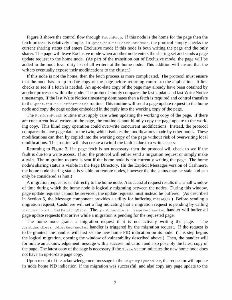
Figure 3: Flow chart of prot fault::FetchPage() and prot fault::FetchHomeNode().
6
Figure 3 shows the control flow through FetchPage. If this node is the home for the page then thefetch process is relatively simple. In prot fault::FetchHomeNode, the protocol simply checks thecurrent sharing status and enters Exclusive mode if this node is both writing the page and the onlysharer. The page will leave Exclusive mode when another node enters the sharing set and sends a pageupdate request to the home node. (As part of the transition out of Exclusive mode, the page will beadded to the node-level dirty list of all writers at the home node. This addition will ensure that thewriters eventually expose their modifications to the cluster.)
If this node is not the home, then the fetch process is more complicated. The protocol must ensurethat the node has an up-to-date copy of the page before returning control to the application. It firstchecks to see if a fetch is needed. An up-to-date copy of the page may already have been obtained byanother processor within the node. The protocol simply compares the last Update and last Write Noticetimestamps. If the last Write Notice timestamp dominates then a fetch is required and control transfersto the prot fault::PerformFetch routine. This routine will send a page update request to the homenode and copy the page update embedded in the reply into the working copy of the page.
The PerformFetch routine must apply care when updating the working copy of the page. If thereare concurrent local writers to the page, the routine cannot blindly copy the page update to the work-ing copy. This blind copy operation could overwrite concurrent modifications. Instead, the protocolcompares the new page data to the twin, which isolates the modifications made by other nodes. Thesemodifications can then by copied into the working copy of the page without risk of overwriting localmodifications. This routine will also create a twin if the fault is due to a write access.
Returning to Figure 3, if a page fetch is not necessary, then the protocol will check to see if thefault is due to a write access. If so, the protocol will either send a migration request or simply makea twin. The migration request is sent if the home node is not currently writing the page. The homenode’s sharing status is visible in the Page Directory. (In the Explicit Messages version of Cashmere,the home node sharing status is visible on remote nodes, however the the status may be stale and canonly be considered as hint.)
A migration request is sent directly to the home node. A successful request results in a small windowof time during which the home node is logically migrating between the nodes. During this window,page update requests cannot be serviced; the update requests must instead be buffered. (As describedin Section 5, the Message component provides a utility for buffering messages.) Before sending amigration request, Cashmere will set a flag indicating that a migration request is pending by callingcsm protocol::SetPendingMigr. The prot handlers::PageReqHandler handler will buffer all
page update requests that arrive while a migration is pending for the requested page.The home node grants a migration request if it is not actively writing the page. The
prot handlers::MigrReqHandler handler is triggered by the migration request. If the request isto be granted, the handler will first set the new home PID indication on its node. (This step beginsthe logical migration, opening the window of vulnerability described above.) Then, the handler willformulate an acknowledgement message with a success indication and also possibly the latest copy ofthe page. The latest copy of the page is necessary if the Stale vector indicates the new home node doesnot have an up-to-date page copy.
Upon receipt of the acknowledgement message in the MigrReplyHandler, the requestor will updateits node home PID indication, if the migration was successful, and also copy any page update to the
7
working copy. If the migration request was not successful, the requestor will create a twin.After completion of FetchPage, control will return to the appropriate page fault routine
(ReadPageFault or WritePageFault). The ReadPageFault routine will release the node lock, changethe VM permissions to Read-only and then return control to the application.
The completion of WritePageFault requires a few more steps. First, the processor will release theassociated node lock. Then, the processor will flush the message store in order to process any messagesthat may have been buffered during the fault handler’s migration attempt. Then the processor will addthe page ID to its local dirty list. Finally, the processor can upgrade VM permissions to Read/Writeand return control to the application.
3.2 Protocol Acquires
Protocol acquires are relatively simple operations. During an acquire, Cashmere will invalidate allpages listed by the accumulated write notices. Before the invalidation can occur however, the writenotice structure must be specially processed.
As will be described in Section 4.3, write notices are stored in a two-level structure consisting ofa global, per-node level and a local, per-processor level. To begin an Acquire, Cashmere will firstdistribute write notices from the global write notice list to the local write notice lists. (This step is notnecessary in the explicit messages version of Cashmere where distribution occurs when the message isreceived.) Then, the processor will invalidate all pages listed in its local write notice list.
The invalidation process is straightforward except in the case where the target page is dirty (i.e. mod-ified) locally. In this case, the protocol will flush the modifications to the home node before invalidatingthe page.
3.3 Protocol Releases
In response to a Release operation, Cashmere will expose all local modifications to the entire cluster.Beginning in prot release::Release, Cashmere will first distribute any pages in the node-level dirtylist to the local dirty list. Then, the protocol can traverse the local dirty list and expose all modifications.
At the home node, all processors work directly on the master copy. Therefore, all modifications arealready in the home node copy, so a processor must only send out write notices to expose the changes.The write notices are sent to all nodes sharing the modified page.
At a remote node, the modifications must be sent to the home for incorporation into the master copy.The modifications are sent to the home through a diff operation.
�
If there are local concurrent writers,the protocol will also update the twin to reflect the current state of the working page. This updatewill eliminate the possibility of sending the same modifications twice. If there are no local concurrentwriters, the protocol will release the twin, freeing it for use in some subsequent write fault on anotherpage (see Section 4.2).
�
The modifications can be pushed to the network either by using the Memory Channel’s programmed I/O interface orby copying them into a contiguous local buffer, which is then streamed to the network. The former is faster, while the latter(poorly) emulates a DMA-based interface. This choice is controlled by the CSM DIFF PIOmacro in csm internal.h.
8
Cashmere leverages the hardware shared memory inside the SMPs to reduce the number of diffoperations. First, if a page has multiple writers within the node and the Release operation is part of abarrier, the diff will be performed only by the last writer to enter the barrier. Second, before performinga diff, Cashmere always compares the last Release and the page’s last Flush timestamps. If the Flushtimestamp dominates, another node is either currently flushing or has already flushed the necessarymodifications. In this case, Cashmere must wait for the other processor to complete the flush and thenit can send the necessary write notices. Cashmere can determine when the flush operations are completeby checking the diff bit in the page’s Directory entry (see Section 4.1).
After the diff operation is complete, the processor can send out the necessary write notices anddowngrade the page sharing and VM permissions to Read. This downgrade will allow future writeaccesses to be trapped.
Ordering between Diffs and Write Notices Cashmere requires that the diff operation is completebefore any write notices can be sent and processed. The Memory Channel version of Cashmere relies onthe Memory Channel’s total ordering guarantee. Cashmere can establish ordering between the protocolevents simply by sending the diff before sending the write notices.
The Explicit Message version of Cashmere does not leverage the network total ordering, and sodiffs must be acknowledged before the write notices can be sent. To reduce the acknowledgementlatency, Cashmere pipelines diff operations to different processors. The code in Release basicallycycles through the dirty list and sends out the diffs. If the diff cannot be sent out because the appropriatemessage channel is busy, the page is placed back in the dirty list to be re-tried later.
The code keeps track of the number of outstanding diff messages and stalls the Release operationuntil all diff operations are complete.
4 Services Component
The Services component provides many of the basic mechanisms to support the Protocol component.Figure 4 shows the structure of the Services component. In this Section, we will discuss the core classesthat compose the Services component. The Page Directory component implements the global pagedirectory. The Twins component provides a mechanism that manages and performs Twin operations.The Write Notices component enables processors to send write notices throughout the system, and theMemory Allocation component provides an implementation of malloc. In the following sections, wediscuss the Page Directory, Twins, Write Notices and Memory Allocation components.
4.1 Page Directory
The Page Directory maintains sharing information for each page of shared memory. The Directory hasone entry per page, and is logically split into two levels. The global level maintains sharing informationon a per-node basis, while the node level is private to each node and maintains sharing informationfor the local processors. The global level is implemented to allow concurrent write accesses withoutrequiring locking, while the node level serializes accesses via fast hardware shared memory locks.
9
_csm_servicesServices
_csm_twinTwins
_csm_pagedir_tPage directory
_csm_write_notices_tWrite notices
_csm_mallocMemory allocation
Figure 4: Services component structure.
Shared Node 0 Node 1 Node 2
Bits: Description 0-4: Home PID 5: Exclusive status6-10: Last Holder 11: Home Node Bound Flag 30: Entry Locked Flag 31: Untouched Flag
Bits: Description 0-2: Sharing status
Figure 5: Logical structure of the global directory entry.
10
Global Page Directory Entry The logical structure of a global page directory entry is pictured inFigure 5. The entry consists of a Shared word and then a set of per-node words. As described below,the separation between the Shared word and the per-node words is necessary to support home nodemigration. The Shared word contains the following information:
Home PID Processor ID of the home.
Exclusive Flag Boolean flag indicating if page is in Exclusive mode.
Last Holder The Processor ID that last acquired the page. This item is provided for Carnival [6](performance modeling) support.
Home Node Bound Flag Boolean flag indicating if home node is bound and cannot migrate.
Entry Locked Flag Boolean flag indicating if entry is locked.
Untouched Flag Boolean flag indicating if page is still untouched.
The per-node words only contain the node’s sharing status (Invalid, Read, or Read/Write) and a bitindicating if a Diff operation is in progress.
The global directory entry is structured to allow concurrent write accesses. First, the Shared word isonly updated by the home node, and the other words are only updated by their owners. The entry canbe updated concurrently by this strategy, however, a processor must read each of the per-node wordsin order to determine the global sharing set. We have evaluated this strategy against an alternative thatuses cluster-wide Memory Channel-based locks to serialize directory modifications, and found that our“lock-free” approach provides a performance improvement of up to 8% [8].
The Shared word provides a single location for storing the home PID. A single location is necessaryto provide a consistent directory view in the face of home node migration. It also provides a naturallocation for additional information, such as the Exclusive flag.
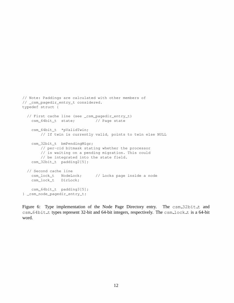
Node Page Directory Entry The node level of the page directory entry maintains sharing informationfor processors within the node. The logical structure is very simple: the entry contains the sharing status(Invalid, Read, Read/Write) for each of local processors. Instead of picturing the logical structure ofthis entry, it is more informative to examine the implementation. Figure 6 shows the type definition.The state field is split into bit fields that indicate the sharing state for each local processor. The otherfields are used during protocol operation:
pValidTwin A pointer to the twin, if twin is attached.
bmPendingMigr A bitmask indicating which local processors have a migration operation pending.
NodeLock A local node lock used to provide coarse-grain serialization of protocol activities.
DirLock A local node lock used only in low-level routines that modify the directory, thus allowingadditional concurrency over the NodeLock.
Padding A measure�
to eliminate false sharing.�
The padding fields are unused by the protocol, however they can be used to store information during debugging. Severalaccess functions are included in the Cashmere code.
11
// Note: Paddings are calculated with other members of// _csm_pagedir_entry_t considered.typedef struct {
// First cache line (see _csm_pagedir_entry_t)csm_64bit_t state; // Page state
csm_64bit_t *pValidTwin;// If twin is currently valid, points to twin else NULL
csm_32bit_t bmPendingMigr;// per-cid bitmask stating whether the processor// is waiting on a pending migration. This could// be integrated into the state field.
csm_32bit_t padding2[5];
// Second cache linecsm_lock_t NodeLock; // Locks page inside a nodecsm_lock_t DirLock;
Figure 6: Type implementation of the Node Page Directory entry. The csm 32bit t andcsm 64bit t types represent 32-bit and 64-bit integers, respectively. The csm lock t is a 64-bitword.
12
Directory Modifications The Page Directory is global and replicated on each node. The method usedto propagate modifications depends on the specific Cashmere version. The Memory Channel version ofCashmere uses the Memory Channel’s inexpensive broadcast mechanism to broadcast changes as theyoccur. As described above, the structure of the directory entry allows concurrent write accesses.
The Explicit Messages version of Cashmere, by necessity, avoids any broadcasts. Instead, a mastercopy of each entry is maintained at the entry’s home node. Remote nodes simply cache copies of thedirectory entry. This Cashmere version must ensure that the master directory entry on the home nodeis always kept up-to-date. Also, Cashmere must ensure that up-to-date information is either passed toremote nodes when needed or that the actions of a remote node can tolerate a stale directory entry.
The three key pieces of information in the directory are the sharing set, the home PID indication,and the Exclusive flag. In the following paragraphs, we examine how the Explicit Messages version ofCashmere propagates changes to these pieces of information.
The global sharing set needs to be updated when a new node enters the sharing set via a Read orWrite fault or exits the sharing set via an Invalidation operation. In the former case, the node willalso require a page update from the home node. Cashmere simply piggybacks the sharing set updateonto the page update request, allowing the home node to maintain the master entry. In the latter casehowever, there is no existing communication with the home node to leverage. Instead, as part of everyInvalidation operation, Cashmere sends an explicit directory update message to the home node. Thesesteps allow both the master copy at the home node and the copy at the affected node to be properlymaintained.
Unfortunately, with this strategy, other nodes in the system may not be aware of the changes to thesharing set. In the Cashmere protocol, a remote node only needs the sharing set during one operation:the issuing of write notices. Fortuitously, this operation follows a diff operation that communicateswith the home node. The home node can simply piggyback the current sharing state on the diff ac-knowledgement, allowing the processor to use the up-to-date sharing set information to issue writenotices.
The home PID indication also needs to be updated as the home node is initially assigned (or subse-quently migrated). We use a lazy technqiue to update this global setting. A processor with a stale homePID indication will eventually send a request to the incorrect node. This node will forward the requestto the home node indicated in its cached directory entry. This request will be repeatedly forwardeduntil it reaches the home node. The home node always piggybacks the latest sharing set and home PIDindication onto its message acknowledgements. The message initiator can then use this information toupdate its cached entry.
The csm packed entry t is provided to pack a full directory entry (home PID, sharing set, boundflag) into a 64-bit value, and this 64-bit value can be attached to the acknowledgements. It is beneficialto pack the entry because Memory Channel packets on our platform are limited to 32 bytes.
�
Anunpacked directory entry will result in an increased number of packets and higher operation latency.
Management of the Exclusive flag is simplified by the Cashmere design, which only allows the homenode to enter Exclusive mode. This design decision was predicated on the base Cashmere version,which allows home node migration. A page in Exclusive mode has only one sharer and that sharerhas Read/Write access to the page. By definition then, the home node will have migrated to the single
�
The packet size is limited by our Alpha 21164 microprocessors, which cannot send larger writes to the PCI bus. [3]
13
writer, and so Exclusive mode can only exist on the home node. When the home node is enteringExclusive mode, it can simply update the master entry. The remote nodes do not need to be aware ofthe transition; if they enter the sharing set, they will send a page update request to the home node, atwhich point the home can leave Exclusive mode.
The remaining pieces of information in the directory entry are the Last Holder value, the HomeNode Bound flag, the Entry Locked flag, and the Untouched flag. The Last Holder value is currentlynot maintained in the explicit messages version of Cashmere. (Carnival, in fact, has not been updatedto run with any Cashmere versions.) The Home Node Bound flag is propagated lazily on the messageacknowledgements from the home node. The remaining two flags are only accessed during initialization(which is not timed in our executions) and still use the Memory Channel. Future work should changethese to use explicit messages.
4.2 Twins
The Twins component manages the space reserved for page twins, and also performs basic operationsto manage twins and diffs. The Twin component interface exports two sets of functions to handle themanagement and the basic operations. The exported interface and underlying implementation are foundin csm twins.h and svc twins.cpp.
The twin space is held in shared memory to allow processors within the node to share the sametwins. Upon allocation, the twins are placed into a list (actually a stack) of free twins. The stack isstored inside the twins themselves. The csm twin::m pHead value points to the first twin in the stack,and then the first word of each twin in the stack points to the next twin in the stack. When a processorneeds to attach a twin to a page, it simply pops a twin off the top of the free stack. If the stack isempty, the Twin component automatically allocates additional space. When finished using the twin,the processor releases the twin, placing it at the top of the free stack. The two relevant functions in theexternal interface are AttachTwin and ReleaseTwin.
The interface also exports several functions to perform twinning and diffing of pages. The diffingfunctions include variants that handle incoming diffs (see Section 3). Diffing is performed at a 32-bitgranularity, and is limited by the granularity of an atomic LOAD/STORE operation.
�
The most complex part of the Twin component implementation is the management of the twin space.Due to the on-demand allocation of twin space and the sharing of twins between processors, each pro-cessor must ensure that it has mapped a particular twin before it can be accessed. Inside the Twincomponent, all accesses to a twin are preceeded by a AttachTwinSpace call that ensures proper map-pings are maintained. Note that this call to AttachTwinSpace is even required when releasing a twin,because the twin space is used to implement the free list.
4.3 Write Notices
The Write Notices component provides a mechanism to send and store write notices. The componentuses a two-level scheme where write notices are sent from one node to another node, and then later
�
Our diffing implementation is based on an XOR operation, but is still limited to a 32-bit granularity due to conflictingaccesses between multiple concurrent writers within the node.
14
distributed to processors within the destination.The Memory Channel version of Cashmere uses a two-level data structure to implement the write
notice support. The top level is a global structure that allows nodes to exchange write notices. Thestructure is defined by csm write notices t in csm wn.h. Each node exports a set of write notice binsinto Memory Channel space. Each bin is owned uniquely by a remote node, and only written by thatnode. Each bin also has two associated indices, a RecvIdx and a SendIdx. These indices mark the nextpending entry on the receiver and the next open entry for the sender. The two indices enable the bins tobe treated as a wrap-around queue.
To send a write notice in the Memory Channel version of Cashmere, a processor first acquires a nodelock corresponding to the destination bin, and then uses remote write to deposit the desired write noticein the destination bin. The write notice is written to the entry denoted by the current SendIdx value,and then SendIdx is incremented. Finally, the sender can release the associated node lock.
Periodically, the receiver will process each bin in the global write notice list. The receiver beginswith the entry denoted by the RecvIdx, reads the write notice, sets the entry to null, and then incrementsthe RecvIdx. The write notice is then distributed to node-level write notice lists (defined in csm wn.h)corresponding to the processors on the node. This node-level list also contains an associated bitmapwith one entry per page. Each bitmap entry is asserted when a write notice is in the list and pending forthat page. This bitmap allows Cashmere to avoid placing duplicate entries in the list.
Both SendIdx and RecvIdx are placed in Memory Channel space, and modifications to these indicesare reflected to the network. The sender and receiver always have current notions of these variables andcan detect when the bin is full. In this case, the sender will explicitly request the receiver to empty itswrite notices bin. The explicit request is sent as a message via the RemoteDistributeWN function.
The Explicit Messages version of Cashmere uses the messaging subsystem to exchange writenotices between nodes, and therefore does not use the global level write notices. The write no-tices are simply accumulated into a local buffer, and then the caller is required to perform acsm write notices t::Flush. This call passes the local buffer filled with write notices to the Mes-
sage component, which then passes the write notices to a processor on the destination node.The message handler on the destination simply distributes the write notices directly to the affected
node-level write notice lists.
4.4 Memory Allocation
The Memory Allocation component provides memory allocation and deallocation routines. This com-ponent is only available in the latest version of Cashmere. In our current environment, we performfrequent comparisons between the latest Cashmere and old legacy versions. For this reason, the newMemory Allocation component is not enabled; instead, we use an older malloc routine (found incsm message/msg assist.cpp) that is consistent with the malloc in our legacy versions.
The new Malloc component has been tested, however, and is available for use in programsthat require frequent allocation and deallocation. The component can be enabled by asserting theCSM USE NEW MALLOC macro in csm internal.h.
15
5 Message Component
The Message component implements a point-to-point messaging subsystem. Each processor has a setof bi-directional links that connect it to all other processors in the system. The link endpoints areactually buffers in Memory Channel space that are accessed through remote write.
_csm_messageMessaging
_csm_rtagReply Tags
_msg_storeMessage Buffering
_msg_send_dataData Payload
CListPool<_csm_dmsg_data_t>Data Buffer Pool Management
Figure 7: Message component structure.
The component is an aggregate of a set of core routines and a number of support components (seeFigure 7). The core routines perform the message notification, detection, and transfer. The supportis comprised of the Reply Tags, the Message Buffering, the Data Payload, and the Data Buffer PoolManagement components.
The Reply Tags component provides a mechanism to track pending message replies. The MessageBuffering component maintains a queue of buffered messages that could not be handled in the currentCashmere state. The Data Payload component contains a set of routines to construct the data payloadsof each message, and the Data Buffer Pool Management component maintains a pool of data buffers tobe used in assembling message replies.
The core routines can be found in msg ops.cpp, and the support classes can be found inmsg utl.cpp. The msg assist.cpp file contains routines that serve as helpers for clients accessingthe Message component. These helper routines translate incoming parameters into Message compo-nent structures and invoke the appropriate messaging interface.
The message subsystem is based on a set of pre-defined messages and their associated message han-dlers. In the following section, we discuss the message types and the structure of the associated han-dlers. Section 5.2 then discusses the implementation of a round-trip message and Section 5.3 describesthe steps necessary to add a new message.
16
5.1 Messages and Handlers
The Message component defines a number of message types, each distinguished by a unique MessageID (MID) (see msg internal.h). Message types exist for requesting page updates, performing diffoperations, and requesting migration, among other tasks. Messages are categorized into three deliveryclasses:
Sync Synchronous message. The Messaging subsystem will send the message and wait for a replybefore returning control to the sender.
ASync Asynchronous message. The subsystem will return control to the sender immediately aftersending the message. The receiver is expected to send a reply, but the sender must periodicallypoll for it with csm message::ReceiveMessages().
Very-ASync Very Asynchronous message. This class is the same as ASync, except that the receiverwill not reply to the message.
All messages have an associated set of handlers, as defined by the csm msg handler t structure inmsg internal.h (see Figure 8).
Figure 8: Type definitions for the structure used to associate handlers with a message.
17
The “Pre” Handler Incoming messages are initially handled by the Pre handler. This handler isresponsible for reading the message body, performing the appropriate action, and then formulating areply if necessary. The handler’s return code instructs the core messaging utility on how to proceed. APre handler has the choice of four actions:
Reply return the formulated reply to the requestor
Store this message cannot be processed currently, so store it in a message buffer for later processing
Forward this message cannot be handled at this processor, so forward it to the specified processor
No-Action No further action is necessary
The “Post” Handler Like the Pre handler, the Post handler is executed at the message destination.The core messaging utility will act on the Pre handler’s return code (for example, send the reply for-mulated by the handler) and then invoke the Post handler. This handler is responsible for performingany necessary cleanup. The handler returns an integer value, however currently the value is ignored bythe core messaging utility.
The “Reply” Handler The Reply handler is called at the message source, whenever the reply isultimately received. This handler is necessary to support the pipelining of messages. Pipelining acrossmessages to multiple processors can be accomplished by using Asynchronous messages. As describedabove, the Message component returns control to the caller immediately after sending an Asynchronousmessage. The Reply handler provides a call-back mechanism that the Message component can use toalert the caller that a reply has been returned. After the Message component executes the Reply handler,it can then clear the reply buffer. The Reply handler thus serves the dual purpose of notifying the callerwhen a reply has arrived and notifying the Message component when a reply buffer can be cleared.
The handlers are called directly from the core messaging routines, and so they must adhere to a wellknown interface. At times however, the handlers must be passed some type of context. For example, aPre handler may need to pass information to the Post handler, or a Reply handler may need to be invokedwith certain contextual information. Cashmere solves this problem by including a hook parameter ineach handler call. There are two types of handler hooks. The csm msg reply hook t structure ispassed to the Reply handler. A messaging client is responsible for allocating and destroying it. Thecsm msg post hook t structure is allocated as a temporary variable by the core messaging routines and
passed from the Pre to the Post handler. The reply hook structure uses a more concise format since itsmembers are dependent on the type of the hook. The message post hook structure should eventually beupdated to use the same type of structure. The two types are shown in Figure 9.
Example A page update message obtains the latest copy of a page and copies that data into the localworking copy of the page. The Pre handler of this message first ensures that the local processor hasread permission for the page, and then formulates a reply with the appropriate page data. The coremessage utility executes the Pre handler, returns the reply, and then calls the associated Post handler.Based on information stored in the message post hook, the Post handler restores the VM permission for
18
// _csm_msg_post_hook_t// This structure is used to pass information from the pre-hook to// the post-hook. The pre-hook only needs to fill in the information// which its corresponding post-hook will need. (Note that most of// this information is available in the incoming packet, but there// is no guarantee that the packet will be available at post time.typedef struct {
// _csm_msg_reply_hook_t// Reply handlers are called from various places by the messaging// subsystem. Clients of the messaging subsystem can pass arguments// to the reply handler through this structure. The structure simply// contains a type field and a void *. The void * should point to the// argument structure, as defined by the client.// ‘‘rhk’’ stands for reply hook.
const int _csm_rhk_null = 0;const int _csm_rhk_req_page = 1;const int _csm_rhk_req_qlock = 2;const int _csm_rhk_malloc = 3;const int _csm_rhk_diff = 4;
typedef struct {
int type; // one of the above _csm_rhk_* constsvoid *psArgs; // Points to a structure determined by the type
} _csm_msg_reply_hook_t;
// Each type of reply hook has a special rhk type. A simple example:typedef struct {
csm_64bit_t vaddr;csm_64bit_t tsStart; // Timestamp at start of fetchint bWrite; // Is this a write access?csm_64bit_t action; // Action taken by home nodeunsigned long start;
} _csm_rhk_req_page_t;
Figure 9: Message hook types used to pass context to the handlers.
19
the page, thus allowing the permission operation to overlap the reply handling on the source node. TheReply handler on the source node simply parses the reply and copies the page data to the local workingcopy.
struct _csm_dmsg_header_t{
csm_v64bit_t mid; // Message IDcsm_v64bit_t reqno; // Request numbercsm_v64bit_t size; // Size of messagecsm_v64int_t iSrcPid; // Source of current msg
// (reqs and replies are separate msgs)csm_v64bit_t bInUse; // True if this link is in-usecsm_v64bit_t options[11];
};
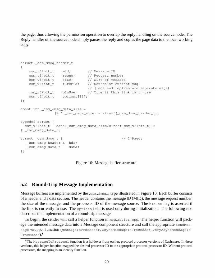
const int _csm_dmsg_data_size =(2 * _csm_page_size) - sizeof(_csm_dmsg_header_t);
Message buffers are implemented by the csm dmsg t type illustrated in Figure 10. Each buffer consistsof a header and a data section. The header contains the message ID (MID), the message request number,the size of the message, and the processor ID of the message source. The bInUse flag is asserted ifthe link is currently in use. The options field is used only during initialization. The following textdescribes the implementation of a round-trip message.
To begin, the sender will call a helper function in msg assist.cpp. The helper function will pack-age the intended message data into a Message component structure and call the appropriate SendMes-
sage wrapper function (MessageToProcessor, AsyncMessageToProcessor, VeryAsyncMessageTo-Processor).
�
�
The MessageToProtocol function is a holdover from earlier, protocol processor versions of Cashmere. In theseversions, this helper function mapped the desired processor ID to the appropriate protocol processor ID. Without protocolprocessors, the mapping is an identity function.
20
In SendMessage, the core messaging utility will first create an rtag to mark the pending messagereply. Then the messaging utility will copy the message header and data to the request channel’sTransmit region. Different methods are used to copy data (i.e. 64-bit copy, 32-bit copy, or a diffoperation) depending on the MID. The different copy routines are contained in the msg send data
class. In the final step of sending a message, the messaging utility will assert the recipient’s polling flagby writing to the associated Transmit region.
The process of receiving a message begins when an application’s polling instrumentation detects anasserted polling flag. The instrumentation transfers control to the ReceiveMessages function. Thisfunction examines all the incoming request and reply channels and begins processing a message (orreply). The first step in processing is to compare the MID against the current message mask. AnyMIDs that are currently masked are moved from the message buffer to a message store managed by themsg store class. The message must be removed from the buffer in order to avoid possible deadlock
(especially in Cashmere versions that may require forwarding). When the mask is reset, the caller isresponsible for explicitly flushing the message store via a call to FlushMsgStore.
If the message is not masked then the core messaging utilities will process the message via theappropriate Pre and Post handlers. This step of processing depends on the MID, the message type, andthe installed handlers (see csm message::HandleMessage()).
Both requests and replies are processed through ReceiveMessages, although requests are handledthrough HandleMessage and replies are handled through ReceiveReply. A messaging client is respon-sible for calling RecieveMessages so that the incoming request or reply can be handled or stored. Oncethe message is removed from the buffer, either because processing is finished or because the messageis stored, the channel’s bInUse flag will be reset. The sender can then push another message throughthe channel.
5.3 Adding a New Message Type
There are four steps to adding a new message type:
� Add a new MID into msg internal.h. The new MID must not share any asserted bits (asidefrom the 0x0feed prefix) with existing mids.
� Create a helper function that builds the Message component data structures and invokes the ap-propriate SendMessage wrapper. This function should be placed in msg assist.cpp.
� Add the appropriate Pre, Post, and/or Reply handlers to msg assist.cpp. The necessary handlerswill be determined by the type of message and the necessary processing.
� Register the handlers in the csm daemon register handlers function.
The most difficult step is to determine the necessary handlers. Pre handlers are mandatory for allmessages. Post handlers are only necessary when some type of “cleanup” is needed after the reply issent. Reply handlers are needed only when the reply has data to be processed.
21
6 Synchronization Component
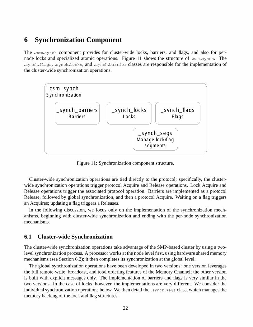
The csm synch component provides for cluster-wide locks, barriers, and flags, and also for per-node locks and specialized atomic operations. Figure 11 shows the structure of csm synch. Thesynch flags, synch locks, and synch barrier classes are responsible for the implementation of
the cluster-wide synchronization operations.
_csm_synchSynchronization
_synch_flagsFlags
_synch_locksLocks
_synch_barriersBarriers
_synch_segsManage lock/flag
segments
Figure 11: Synchronization component structure.
Cluster-wide synchronization operations are tied directly to the protocol; specifically, the cluster-wide synchronization operations trigger protocol Acquire and Release operations. Lock Acquire andRelease operations trigger the associated protocol operation. Barriers are implemented as a protocolRelease, followed by global synchronization, and then a protocol Acquire. Waiting on a flag triggersan Acquires; updating a flag triggers a Releases.
In the following discussion, we focus only on the implementation of the synchronization mech-anisms, beginning with cluster-wide synchronization and ending with the per-node synchronizationmechanisms.
6.1 Cluster-wide Synchronization
The cluster-wide synchronization operations take advantage of the SMP-based cluster by using a two-level synchronization process. A processor works at the node level first, using hardware shared memorymechanisms (see Section 6.2); it then completes its synchronization at the global level.
The global synchronization operations have been developed in two versions: one version leveragesthe full remote-write, broadcast, and total ordering features of the Memory Channel; the other versionis built with explicit messages only. The implementation of barriers and flags is very similar in thetwo versions. In the case of locks, however, the implementations are very different. We consider theindividual synchronization operations below. We then detail the synch segs class, which manages thememory backing of the lock and flag structures.
22
Barriers Barriers are implemented with a single manager that gathers entrance notifications fromeach node and then toggles a sense variable when all nodes have arrived at the barrier.
Figure 12: Type implementation of Cashmere barriers.
The type definitions for a barrier ar shown in Figure 12. Again, the structure follows a two-levelimplementation. The csm barrier t is held in shared memory, while the csm global barrier t ismapped as a broadcast Memory Channel region. The m bmArrivalsNode and m EntranceCtrl fieldsin csm barrier t track the processors within the node that have entered the barrier. The former field isa bitmap identifying the particular processors; it is passed into the prot release::Release functionso that the code can determine when the last sharer of a page has arrived at the barrier. (During abarrier, only the last sharer needs to perform a diff.) The latter field counts the local processors thathave arrived at the barrier. By analogy, the m ExitCtrl field counts the number of processors that haveleft the barrier.
The last processor on a node to arrive at the barrier notifies the manager of its node’s arrival. Incsm global barrier t, the manager maintains an array of per-node arrival flags. In the Memory
Channel version of Cashmere, these arrival flags are kept in Memory Channel space, so they can beupdated with remote write. In the explicit messages version, the flags are updated via an explicitCSM DMSG BARRIER ARRIVAL message.
When all nodes have arrived at the barrier, the master toggles the global sense field incsm global barrier t. Again, this field is updated either via remote write or by an explicitCSM DMSG BARRIER SENSE message, depending on the Cashmere version.
In the explicit messages version, the master sends individual CSM DMSG BARRIER SENSE messagesto the other nodes. Our prototype platform has eight nodes, so this simple broadcast mechanism isreasonable. If the number of nodes wee to increase, a tree-based barrier scheme might provide betterperformance.
23
Locks The synch locks class provides mutual exclusion lock operations. An application may per-form an Acquire, a conditional Acquire, or a Release operation.
The Memory Channel-based locks take full advantage of the special network features. In the code,these locks are referred to as ilocks.
�
The locks are represented by an array with one element pernode, and are mapped on each node into both Receive and Transmit regions. The regions are mappedfor broadcast and loopback.
A process begins by acquiring a local node lock. It then announces its intention to acquire an ilock byasserting its node’s element the array via a write to the appropriate location in the Transmit region. Theprocess then waits for the write to loopback to the associated Receive region. When the write appears,the process scans the array. If no other elements are asserted, then the lock is successfully acquired.Otherwise, a collision has occurred. In the case of a normal Acquire, the process will reset its entry,back off, and then try the acquire again. In the case of a conditional Acquire, the operation will fail.The lock can be released simply by resetting the node’s value in the lock array.
This implementation depends on the Memory Channel. First, it uses remote writes with broadcast toefficiently propagate the intention to acquire the lock. It also relies on total ordering to that each nodesees the broadcast writes in the same order.
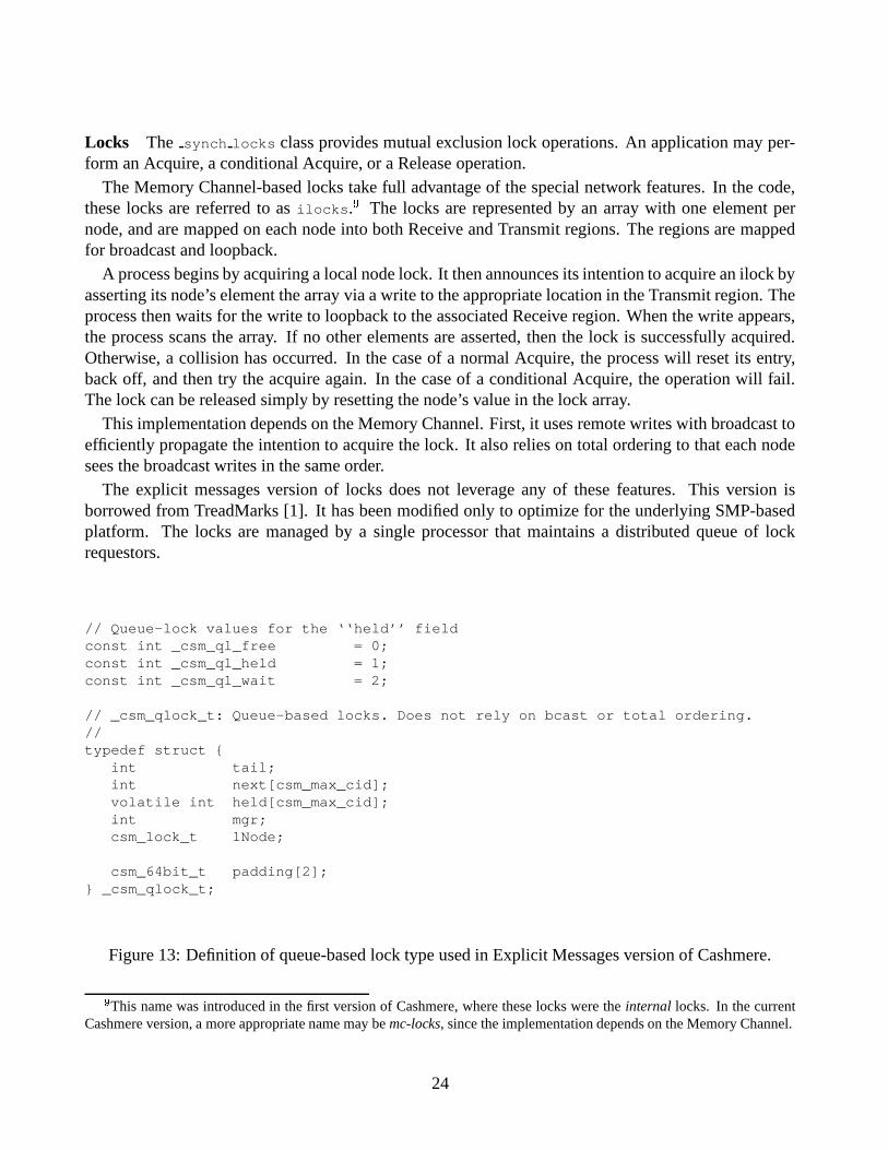
The explicit messages version of locks does not leverage any of these features. This version isborrowed from TreadMarks [1]. It has been modified only to optimize for the underlying SMP-basedplatform. The locks are managed by a single processor that maintains a distributed queue of lockrequestors.
// Queue-lock values for the ‘‘held’’ fieldconst int _csm_ql_free = 0;const int _csm_ql_held = 1;const int _csm_ql_wait = 2;
// _csm_qlock_t: Queue-based locks. Does not rely on bcast or total ordering.//typedef struct {
int tail;int next[csm_max_cid];volatile int held[csm_max_cid];int mgr;csm_lock_t lNode;
csm_64bit_t padding[2];} _csm_qlock_t;
Figure 13: Definition of queue-based lock type used in Explicit Messages version of Cashmere.
�
This name was introduced in the first version of Cashmere, where these locks were the internal locks. In the currentCashmere version, a more appropriate name may be mc-locks, since the implementation depends on the Memory Channel.
24
The type definition for queue-based locks is pictured in Figure 13. The tail field is valid on themanager node and points to the last processor in the request queue. The next array has one entry perprocessor on the node; each entry points to the succeeding PID in the request queue. The held field isa flag indicating the processor’s request status: free, held, or wait. The mgr field indicates the managerPID of the lock, while the lNode field is a node-level lock that allows any processor on the managernode to perform management operations. This optimization is allowed by the SMP-based platform.
The steps to acquire a queue-based lock are as follows:
1. Place the requestor’s PID at the tail of the request queue.
2. Register the requestor’s intention to acquire the lock at the site of the old tail.
3. The requestor should wait for a lock handoff response from the old tail processor.
If the requestor and lock manager are on different nodes, then the first step is accomplished bysending an explicit CSM DMSG REQ QLOCK message. Upon receipt of this message, the manager willappend the requestor’s PID to the request queue by updating the tail field of its csm qlock t structure.If the requestor and lock manager are on the same node however, the requestor can update the tail
field using the lNode lock to serialize access to shared memory.The second step can also be accomplished through either an explicit message or shared memory,
depending on whether the manager and the tail are on the same node. Through either mechanism, thecsm qlock t structure on the tail node should be updated so that the tail’s next field points to the
requestor.In the third step, the requestor will simply spin until its held field changes to csm ql held. If the tail
is on the same node as the requestor, the tail can set the requestor’s held field directly through sharedmemory; otherwise the tail will send an explicit CSM DMSG ANS QLOCK to the requestor. The associatedmessage handler will set the held field.
Flags The implementation of Cashmere flags is very straightforward. In the Memory Channel ver-sion, the flags are simply mapped as broadcast regions. In the explicit messages version, the broadcastis accomplished via explicit messages.
In the Memory Channel version of Cashmere, both lock and flag structures are mapped as broadcastregions. And while the size of the structures varies, they both require the same VM support. Thesynch segs class manages the associated Memory Channel mappings and provides a mechanism to
map lock or flag IDs to a physical location in memory. The class was designed to allow for dynamicallocation of lock and flag segments.
6.2 Node-level Synchronization
Cashmere also provides a number of functions for synchronizing within a node. The functions providegeneral mutual exclusion locks and also atomic operations. The functions can be split into three cate-gories: “ll”, “local”, and “safe”. A function’s category is specified in its name. The functions can befound in synch lnode.cpp and synch ll.s.
25
The “ll” functions are low-level functions written in assembly language using the Alpha’s LoadLinked/Store Conditional instructions. The Load Linked instruction loads a memory address and setsa guard flag on that address. A Store operation to that address (by any local processor) automaticallyresets the guard flag. A Store Conditional operation succeeds only if the guard flag is still set. Thesetwo instructions can then be used to implement various atomic operations.
The “ll” functions attempt to perform their atomic operation once, but may fail because of a con-current Store. The higher level “local” functions repeatedly call the respective “ll” function until theoperation succeeds. The “local” functions also call csm message::ReceiveMessages after a failed“ll” function in order to avoid deadlock.
The “safe” functions are associated with locks. A safe acquire will succeed if the caller already ownsa lock. These functions are used to help allow re-entrancy in message handlers.
7 Miscellaneous Component
The Miscellaneous component contains support routines for optimized data copy operations, exceptionhandlers, and statistics. The component also contains routines to allocate shared memory and MemoryChannel space. See the code for more details.
8 Software Engineering Issues
The Cashmere code is organized in a directory hierarchy reflecting the internal components. Files anddirectories in the hierarchy follow a naming convention that identifies their scope in the hierarchy. Allfiles prefixed with a “csm ” are globally visible; other files are prefixed with the name of the componentin which they are visible.
To help with code readability, Cashmere uses a modified Hungarian Notation convention, which pre-fixes each variable name with a type abbreviation. Table 1 lists many of the prefixes used in Cashmerecode.
In addition to naming conventions, it is recommended that a Cashmere installation employ RCS orsome other source code control system. At the University of Rochester, we have written a local script(bl csm) that builds a level of code. This script attaches a symbolic name to the current version ofeach Cashmere source file, thereby capturing a snapshot of the development process. The script alsoprompts for a set of comments describing the build level and stores these comments in the levels.txtfile stored under the root RCS directory. By convention, a programmer builds a level when a new stablecode version is reached or when the Cashmere system is benchmarked.
9 Debugging Techniques
Cashmere bugs fall into two main categories based on their impact. Bugs in the first category causeCashmere to fail immediately, either by crashing or by failing an assert check. Bugs in the second
26
Prefix Typep pointera array
i, n integerb,f Flag (boolean) valuem class member
sc , s static class membersql sequential list
internal to enclosing scopebm bitmaskdbg debugts timestamp
prx pointer to a Receive regionptx pointer to a Transmit regionphk message post hookrhk message reply hookidx index variablepid processor IDnid node IDcid compute processor ID (ID within the node)
Table 1: Cashmere modified Hungarian Notation.
27
category are caused by races and may not show on all executions or may not manifest themselves untilsome time after the bug occurs.
The first category of bugs can be tracked by using a debugger. Unfortunately, Cashmere currentlyis not able to open each application process under its own debugger. There are a few workarounds tohelp with debugging, however. First, most debuggers can attach to running processes. If Cashmereis invoked with the “-D” flag, then the process will print a message and enter an infinite loop if anassert fails. The user can then attach a debugger to the failed process and check the process state.More simply, the Cashmere application itself can be started inside a debugger. Then process 0 can becontrolled by the debugger. These workarounds are admittedly weak, but hopefully they can be helpfulin limited cases.
The second category of bugs are tracked only by post-mortem analysis of an event log. The eventlog is usually created by the CSM DEBUGF macro. (This macro is ignored in the optimized executable.)The macro takes a debugging level and additional, printf-style arguments; it prints those additionalarguments if the program’s debugging level is greater than or equal to that specified by the initialargument. The debugging level can be set with the “-d:X” command line switch.
Cashmere contains many CSM DEBUGF statements; the number has grown as the code has developed.Currently, the statements are too verbose to trace a lengthy program; they are mainly useful in smalltest cases. CSM DEBUGF tracing is especially ineffective when debugging difficult races. In most cases,the statements significantly perturb execution and eliminate the race. To help debug races, we havedeveloped two test programs and a special debugging log function designed to minimize logging over-head.
The test.cpp program is a relatively simply test of Cashmere. The wtest.cpp program is a muchmore complicated test. Both applications can be found in the CCP hierarchy, which is described inAppendix B. Both operate on a small array, which is partitioned according to the number of processors.The processors operate on all partitions, with the programs verifying data at each computational step.The sharing patterns are relatively easy to follow, but they strongly exercise the Cashmere sharingmechanism. A programmer can view the event logs and track down problems based on the known (andreadily visible) sharing patterns.
As an alternative to CSM DEBUGF statements, the programmer can rely in the test applications ona special csm dbg print test data function, defined in misc ops.cpp. This function is designedis dump a large amount of useful information in as little time as possible, thereby minimizing theperturbation due to logging. The function prints out the first data value in each processor partition,along with the barrier and lock IDs, the local logical clock value, and information specific to the callsite. These calls have been placed in key points throughout the protocol, and can be enabled by assertingCSM DBG TEST in csm internal.h. The macro should be set to “1” in wtest or to “2” in test. To
enable the full set of these calls, also assert the DBG macro in prot internal.h.Calls to csm dbg print are especially effective in debugging the wtest application. The main
computation phase in this application has each processor visit each array element and assert the bitcorresponding to its processor ID. Races are avoided by first obtaining a per-partition lock. This accesspattern creates a large amount of very fine-grain sharing.
When the application fails, it prints out the incorrect array element. The programmer can thendetermine which bit is incorrectly set, and walk backwards through the event log to determine the
28
cause of the failure. This technique is at times tedious, but is often the only way to discover and correcta subtle race condition in the implementation.
In the rare case when even csm dbg print test data creates too much perturbation, a programmercan use the COutputBuffer class in misc uout.[h,cpp] to keep a log directly in memory. Afterfailure, the programmer can arrange for the log to be dumped to screen or disk.
Another useful tool is dis. This tool disassembles an executable, allowing the programmer to asso-ciate a program counter value with a line of source code (assuming the executable includes debugginginformation). Most Cashmere exception handlers print a program counter value so that the exceptioncan be traced to the source code.
29
References
[1] C. Amza, A. L. Cox, S. Dwarkadas, P. Keleher, H. Lu, R. Rajamony, W. Yu, and W. Zwaenepoel.TreadMarks: Shared Memory Computing on Networks of Workstations. Computer, 29(2):18–28, February 1996.
[2] A. Eustace and A. Srivastava. ATOM: A Flexible Interface for Building High Performance Pro-gram Analysis Tools. In Proceedings of the USENIX 1995 Technical Conference, New Orleans,LA, January 1995.
[3] M. Fillo and R. B. Gillett. Architecture and Implementation of Memory Channel 2. DigitalTechnical Journal, 9(1):27–41, 1997.
[4] R. Gillett. Memory Channel: An Optimized Cluster Interconnect. IEEE Micro, 16(2):12–18,February 1996.
[5] L. Kontothanassis, G. Hunt, R. Stets, N. Hardavellas, M. Cierniak, S. Parthasarathy, W. Meira,S. Dwarkadas, and M. L. Scott. VM-Based Shared Memory on Low-Latency, Remote-Memory-Access Networks. In Proceedings of the Twenty-Fourth International Symposium on ComputerArchitecture, pages 157–169, Denver, CO, June 1997.
[6] W. Meira. Understanding Parallel Program Performance Using Cause-Effect Analysis. Ph. D.dissertation, TR 663, August 1997.
[7] R. Stets, S. Dwarkadas, L. I. Kontothanassis, U. Rencuzogullari, and M. L. Scott. The Effectof Network Total Order, Broadcast, and Remote-Write Capability on Network-Based SharedMemory Computing. In Proceedings of the Sixth International Symposium on High PerformanceComputer Architecture, Toulouse, France, January 2000.
[8] R. Stets, S. Dwarkadas, N. Hardavellas, G. Hunt, L. Kontothanassis, S. Parthasarathy, and M.Scott. Cashmere-2L: Software Coherent Shared Memory on a Clustered Remote-Write Network.In Proceedings of the Sixteenth ACM Symposium on Operating Systems Principles, St. Malo,France, October 1997.
[9] R. Stets. Leveraging Symmetric Multiprocessors and System Area Networks in Software Dis-tributed Shared Memory. Ph. D. dissertation, Computer Science Department, University ofRochester, August 1999.
30
A Known Bugs
This Appendix covers known bugs in the current Cashmere system.
� Cashmere with first-touch home nodes (i.e. no migration) crashes in barnes, clu, lu, and water-spatial. The version of the code will run, however, when the home node assignments used in anearlier evaluation [7] are specified via the “-l” switch.
� The wtest application does not run on 32 processors.
� The CC compiler outputs a large number of warnings when compiling the Cashmere library.
31
B Cache Coherence Protocol Environment
In our research environment we commonly use several different shared memory protocols, includingdifferent versions of Cashmere. The Cache Coherence Protocol (CCP) environment provides a singleset of standard code and makefile macros for application development. These macros are mapped atbuild-time to the target protocol. Currently, the CCP environment supports Cashmere, TreadMarks [1],Broadcast Shared Memory [9], and a plain hardware shared memory system. The environment isdesigned in a modular manner such that a new protocol can be incorporated simply by creating amakefile macro definition file and by adding appropriate code macros to an existing program.
In the following sections, we will discuss the CCP code and makefile macros, including some usageexamples. As one specific example, we will describe the Cashmere-CCP build environment.
B.1 CCP Code Macros
The CCP environment contains a set of macros for both C and Fortran source code. These macrosprovide access to the basic operations exported by shared memory protocols, such as initialization,memory allocation, and synchronization. To ensure portability, a CCP program must use these macrosand avoid any direct invocations of a specific protocol’s interface. The program’s entry point, i.e. main(C) or program (Fortran), must also be named CCP MAIN or PROGRAM, respectively. At build-time,CCP replaces these labels with internal labels that allow the protocol to provide the program’s entrypoint.
The complete set of CCP code macros is contained in the ccp.h header file. This file contains theappropriate macro mappings for each supported protocol. The specific mappings are selected by theCCP NAME macro, which is set on the build command line.
Figure 14 contains a small subset of ccp.h. At the top of the file, each supported protocol is givena unique macro setting. The remainder of file is split into sections containing the code macro for theassociated protocol. The Figure shows a subset of the macros in the Cashmere section, including theinclude statements, initialization and lock operations. Sections for the TreadMarks protocol are alsopartially shown in order to provide a flavor of the file’s organization. As noted above, CCP currentlysupports four distinct protocols and also several variants of each protocol.
B.2 CCP Makefile Macros
CCP provides a set of makefile macros that make the build process portable. These macros can beseparated into two groups. Build macros allow the programmer to specify the desired system, alongwith other build parameters. Description macros allow the targets, dependencies, and commands to bespecified in a manner that is portable across the various underlying protocols.
Build Macros There are five build macros that control the selection of underlying protocols and otherbuild options. Normally, these macros are set in the top of the application’s makefile or on the makecommand line. Based on the build macro settings, the description macros are automatically set. Thefive build macros are listed below:
Figure 14: The basic structure of ccp.h. Many macro definitions have been omitted due to spaceconstraints. The online version has the complete macro definitions.
33
PROT controls the choice of shared memory protocol.
LIB VERS specifies the protocol library version.
C VERS specifies protocol-dependent processing that must be performed on the application source.
CLVL controls the compilation level (optimized or debug).
LIB XTRA specifies extra libraries that should be linked.
The file ccp build.txt in the online documentation directory describes the supported settingsfor these macros. Figure 16 shows a simple example that uses the CCP makefile macros, both the buildand description macros, to build a Cashmere application. We will discuss this example further below.
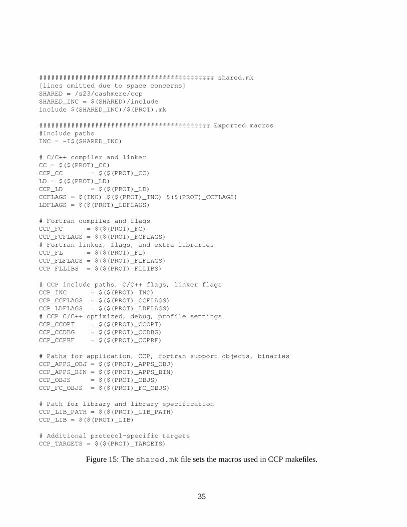
Description Macros The description macros are used to set up the targets, dependencies, and com-mands. The macros ensure that the proper support files are included or linked and that the propertools are invoked with the proper flags. These macros are defined in shared.mk, which is shown inFigure 15. The description macros specify the compiler, linker, tool flags, file locations, and protocol-specific targets. The application makefile should use the macros prefixed with CCP. These macros areset to the protocol-specific settings by a low-level, protocol-specific makefile $(PROT).mk that isincluded at the top of shared.mk. PROT, of course, is a build macro set directly by the programmer.
The protocol-specific makefiles are responsible for exporting all of the macros required byshared.mk. This requirement allows the same makefile to be used for any of the supported CCPprotocols.
Figure 16 shows an example CCP makefile for the sor (successive over-relaxation) application. Themakefile is divided into two main sections. In the first section, the CCP makefile should set the fivebuild macros and then include the shared.mk definition file. (In most versions of make, command-line assignments will override any makefile settings.) As described in the previous paragraph, the buildmacros will drive the description macro settings defined in shared.mk.
In its second section, the CCP makefile defines the targets, dependencies, and commands necessaryto build the application.
B.3 Cashmere-CCP Build Process
The primary tool in the Cashmere-CCP build process is the csm cc script. This script is actually awrapper of the compiler and the linker, and is meant to be called in place of those two tools. The wrap-per script performs a number of pre- and post-processing steps required to create the final Cashmereexecutable.
Figure 17 shows the script’s basic control flow. As mentioned, the script performs either compilationor linking. The initial step in the script is to scan the command line for source files. If source files arepresent, the script will compile the files according to the steps shown in the left of the flow chart.
34
############################################ shared.mk[lines omitted due to space concerns]SHARED = /s23/cashmere/ccpSHARED_INC = $(SHARED)/includeinclude $(SHARED_INC)/$(PROT).mk
Figure 16: Example makefile for the SOR application. The build macros combine with theshared.mk include file to define the CCP description macros.
36
compile or link?
C or fortran?
C compiler
dup_writes(add application
variables and polling)
assembler
f2ccpf(fortran to ccp)
main file?
ccp_appvars(create
application variables)
fortran compiler
common blocks?
ccp_common(create common block definitions)
linker
"Shasta" poll?
xatom(add polling)
object file binary executable
input files: either source or objects
compile link
yes
no
yes
no
yes
no
C fortran
creates new assembly file
instrumented fortranassembly
instrumented assembly
creates new assembly file
binary executable
Figure 17: Control flow for csm cc. Intermediate files are denoted by italicized labels on the transi-tions.
37
Compilation The csm cc script can compile both C and Fortran files. For a C file, the script willfirst use the C compiler to create an assembly file that can be instrumented with Cashmere-related code.The dup writes executable adds polling and/or write doubling
���instrumentation to the assembly file.
The executable also sets a number of variables, which are called application variables by our Cashmeresystem, in the application’s data segment. Cashmere checks the application variables at runtime todetermine how the application was built, i.e. the type of polling or write doubling instrumentation.
The final step in a C source compilation is to run the instrumented assembly file through the compilerto produce the final object file.
The compilation process for Fortran source is slightly different, due to differences in the capabilitiesof the C and Fortran compilers. Our base C compiler (gcc) allows registers to be reserved, while none ofour Fortran compilers have this capability. The polling instrumentation performed by dup writes re-quires two reserved registers, and therefore this instrumentation cannot be used in our Fortran programs.Instead, our Fortran programs use Shasta-style polling, which walks through the binary executable andperforms live register analysis to determine what registers are available at polling sites. This differencein compiler capabilities creates a significant difference in the build processes.
A Fortran source file is first run through the f2ccpf script. This script locates the main entry pointand changes the entry point into an app main subroutine, which is called directly by the Cashmerelibrary. (The Cashmere library hijacks the program’s main entry point in order to perform specialinitialization.) Once the application’s main entry point is identified, the csm cc script will also createa simple assembly file containing the application variables. This assembly file is compiled into anobject file and ultimately linked into the final binary executable. The final step in the compilationprocess is then to compile the instrumented Fortran source file into an object file.
In addition, the Fortran code requires a special interface file to the Cashmere C code. Thefort if.c file in the ccp/src directory provides simple wrapper routines that make the Cash-mere library calls available to the Fortran source. In fact, fort if.c is written using CCP calls,so this interface file makes all CCP-supported protocol libraries available to Fortran applications. Asdescribed in the previous section, the protocol is chosen through the CCP PROT build macro.
Once all the C or Fortran application object files are built, the files can be linked together using thecsm cc script. After linking the executable, Shasta-style polling can also be applied. The followingtext describes the linkage operation.
Linkage To begin the linkage process, the csm cc script uses the ccp common script to parse theobject files for common blocks. (Common blocks are used extensively in Fortran, but the assemblylanguage declaration for common blocks can be used by any high level language.) The ccp commonscript creates a small assembly file with definitions for each common block. These definitions ensurethat the common block addresses fall within any address range required by the underlying protocollibrary.
In the next step, the csm cc script simply links together the specified object files. This step producesa binary executable file. For certain polling choices, i.e. Shasta polling, a final post-processing stepis required to add the polling instrumentation. This step uses the xatom
� �binary modification tool to
���
Write doubling is used by an early Cashmere version [5] to propragate shared data modifications as they occur.� �
The xatom tool is a version of atom [2] that has been modified to allow the insertion of single instructions.
38
place inline polling instrumentation in the binary. As mentioned above, the instrumentation tool usesonly dead registers in the polling instrumentation.