THE IMPLEMENTATION OF FAIL-OPERATIVE FUNCTIONS IN INTEGRATED DIGITAL AVIONICS SYSTEMS Stephen S. Osder Sperry Flight Systems Division SUMMARY System architectures which incorporate fail-operat,ve fl,&ht guidance It is functions within a total integrated avionics complex are described. shown that the mixture of flight critical and non-flight critical functions within a common computer complex is an efficient solution to the integration of navigation, guidance, flight control, display and flight management. Inter- facing subsystems retain autonomous capability to avoid vulnerability to total avionics system shutdown as a result of only a few failures. INTRODUCTION The advent of the airborne digital computer in an attractive practical configuration (from the standpoint of cost, size and power) has set the stage for the emergence of a variety of new avionics system architectures, Despite the continuing growth in requirements for navigation, guidance, control and data management functions, the industry is faced with relentless pressures to hold system costs to pre-1970 levels. tion, but cannot afford increased cost or increased complexity and its con- comitant reliability penalty. that feature a high level of integration and consolidation of functions. deed, the trivial answer to any cost trade-off study of competing avionics architectures is the totally integrated system where a single central computer (of sufficient speed) performs all required functions so that the cost of functional growth is measured only by the cost of the memory increment. This solution does not acknowledge the complicating factors of flight critical fail- operative requirements and the related problems of fault isolation and redun- dnacy management. We require increased system sophistica- The solutions appear in new avionics architures In- The usual approach to defining a system architecture that must provide some fail-operative functions is to separate subsystems into fail-operative and non-fail-operative categories. In this paper it is shown that this type of separation does not result in the most efficient mechanization of the de- sired function. An alternative integrated system architecture that starts with the requirements for the fail-operative autoland and stabilization and control functions is described. It soon becomes apparent that the majority of information interfaces needed for these fail-operative functions are also used 947 https://ntrs.nasa.gov/search.jsp?R=19760024086 2018-09-02T22:21:59+00:00Z
Transcript
THE IMPLEMENTATION OF FAIL-OPERATIVE FUNCTIONS IN
INTEGRATED DIGITAL AVIONICS SYSTEMS
Stephen S . Osder Sperry Flight Systems Division
SUMMARY
System a rch i t ec tu re s which incorpora te fail-operat,ve fl,&ht guidance It is functions wi th in a t o t a l i n t eg ra t ed avionics complex are described.
shown t h a t t he mixture of f l i g h t c r i t i c a l and non-flight cr i t ical functions within a common computer complex is an e f f i c i e n t so lu t ion t o t h e in t eg ra t ion of navigation, guidance, f l i g h t cont ro l , d i sp lay and f l i g h t management. In te r - fac ing subsystems r e t a i n autonomous c a p a b i l i t y t o avoid vu lne rab i l i t y t o total avionics system shutdown as a r e s u l t of only a few f a i l u r e s .
INTRODUCTION
The advent of t h e a i rborne d i g i t a l computer i n an attractive p r a c t i c a l configuration (from the standpoint of cos t , s i z e and power) has set t h e s t age f o r t he emergence of a v a r i e t y of new avionics system a rch i t ec tu re s , Despite t he continuing growth i n requirements f o r navigation, guidance, con t ro l and d a t a management functions, t h e indus t ry is faced with r e l e n t l e s s pressures t o hold system cos t s t o pre-1970 levels. t i on , but cannot a f ford increased cos t o r increased complexity and its con- comitant r e l i a b i l i t y penalty. that f ea tu re a high level of i n t eg ra t ion and consolidation of functions. deed, the t r iv ia l answer t o any cos t trade-off study of competing avionics a rch i t ec tu re s is the t o t a l l y in t eg ra t ed system where a s i n g l e c e n t r a l computer (of s u f f i c i e n t speed) performs a l l required func t ions so t h a t t he cos t of func t iona l growth is measured only by t h e cos t of t h e memory increment. This so lu t ion does not acknowledge the complicating f a c t o r s of f l i g h t c r i t i ca l f a i l - opera t ive requirements and t h e r e l a t e d problems of f a u l t i s o l a t i o n and redun- dnacy management.
W e r equ i r e increased system sophistica-
The so lu t ions appear i n new avionics a r c h i t u r e s In-
The usual approach t o def in ing a system a r c h i t e c t u r e t h a t must provide some fa i l -opera t ive func t ions is t o sepa ra t e subsystems i n t o fa i l -opera t ive and non-fail-operative categories. I n t h i s paper it is shown t h a t t h i s type of separa t ion does not r e s u l t i n t h e most e f f i c i e n t mechanization of t h e de- s i r e d function. An a l t e r n a t i v e in t eg ra t ed system a rch i t ec tu re t h a t starts with the requirements f o r t h e fa i l -opera t ive autoland and s t a b i l i z a t i o n and con t ro l func t ions is described. It soon becomes apparent t h a t t he majority of information i n t e r f a c e s needed f o r these fa i l -opera t ive func t ions are a l s o used
f o r t h e o the r guidance, navigation, d i sp lay and d a t a management requirements. The system a r c h i t e c t u r e and s a f e t y techniques used t o mechanize t h e f a i l - operative requirements can be made completely compatible with the genera l ly accepted methods of implementing t h e non-flight cr i t ical functions.
Expanding from t h e fa i l -opera t ive f l i g h t guidance system, add i t iona l in- t e r f aces are added t o achieve t h e remaining navigation, c o n t r o l and d isp lay functions. These add i t iona l func t ions are t r e a t e d d i f f e r e n t l y i n terms of in- t e r f a c e hardware and software mechanizations because the r a t h e r e l abora t e monitoring and f a u l t i s o l a t i o n rout ines f o r fa i l -opera t ive performance are not required.
The vu lne rab i l i t y of such in t eg ra t ed systems t o t h e t o t a l l o s s of avionics func t ions with only two f a i l u r e s , such as t h e l o s s of two c e n t r a l computers, musk be avoided. Consequently, t he system a r c h i t e c t u r e must make provision f o r continued although degraded operation through the r e t en t ion of autonomous c a p a b i l i t y in the var ious in t e r f ac ing subsystems. These back-up provisions generally appear as r e s i d u a l hardware functions i n con t r a s t t o the software functions which are provided by t h e primary o r c e n t r a l i n t eg ra t ed mode of operation.
This paper presents a b r i e f r a t i o n a l e f o r t h e se l ec t ion of a t o t a l l y in- tegra ted avionics a r c h i t e c t u r e over two o the r competing candidates. organization of t h e t o t a l l y in t eg ra t ed system and the techniques f o r achieving fa i l -opera t ive performance f o r f l i g h t cr i t ical modes are described. n e r a b i l i t y t o t o t a l system shutdown is analyzed, and methods of pro tec t ing aga ins t t h a t v u l n e r a b i l i t y are suggested. I n general , t he p r a c t i c a l f e a s i b i l - i t y of such a t o t a l l y in t eg ra t ed av ionics system appears t o be l imi ted only by questions regarding the manageability of t he system software.
The
The vul-
SYMBOLS AND ABBREVIATIONS
h
M
P i t ch At t i tude
Rol l
Heading
Column Force
Wheel Force
Linear body a x i s accel- e ra t ions i n x, y , z d i r e c t ion
Al t i t ude
Mach number
Q
P S
pT
P F W
TT
vC
INS
Dynamic Pressure
S t a t i c Pressure
To ta l Pressure (PT - Ps) =
Probab i l i t y of f a i l u r e i n t i m e duration t
Tota l Temperature
QC
S t a t i c A i r Temperature
Calibrated Airspeed
Iner t ia l Navigation System
948
ILS Instrument Landing MLS Microwave Landing System System
cws Control Wheel Steer ing MFD Multi-Function Display
aME Distance Measuring Equipment
RATIONALE FOR CANDIDATE SYSTEM ARCHITECTURE SELECTION
Three generic candia te av ionics system a rch i t ec tu re s i l l u s t r a t e the re- quirements, considerations, and controversies surrounding the s e l e c t i o n of an in tegra ted avionics approach f o r f u t u r e t r anspor t a i r c r a f t . da tes are:
These three candi-
1) The Federated System -- a combination of new computers f o r each required class of functions. technology, bu t t h e argument is made t h a t computers are becoming s u f f i c i e n t l y inexpensive t h a t we can af 2ord the separa te computers of t he federated concept. This argument does not address the pro- blem of intercomputer communication and i n t e r f a c e complexity.
The In tegra ted System with Separate, Fail-Operative F l igh t Control Computers -- a major acknowledgment of t h e need f o r i n t eg ra t ion bu t , nevertheless, it continues t o dupl ica te t h e majority of sensor in t e r f aces i n order t o separa te t h e fa i l -opera t ive guidance functions.
This i s a d i r e c t extension of today's
2)
3) The Integrated System with Self-contained, Fail-Operative F l igh t Control Functions -- t h i s system involves a minimum of i n t e r f a c e duplication.
Trade-off analyses of these th ree configurations can be performed t o prove any des i red conclusion merely by applying the desired a r b i t r a r y weighting t o one o r more criteria of i n t e r e s t . Therefore, r a t h e r than perform a quantita- t ive trade-off we w i l l i l l u s t r a t e how a s i n g l e parameter, "the i n t e r f a c e com- plex i ty ," varies with each of t h e candidate a rch i t ec tu re s . It is contended t h a t i n t e r f a c e complexity is the s i n g l e most s i g n i f i c a n t f a c t o r t h a t influences cos t , complexity and r e l i a b i l i t y of d i g i t a l systems. When the computation and l o g i c are performed i n software, t h e l a r g e s t hardware function is the acquisi- t i o n and d i s t r i b u t i o n of t h e d a t a required by the computer. I f we minimize the scope and complexity of t h a t func t ion , w e create t h e simplest , least expensive and most r e l i a b l e system. three candidates with re ference t o Figures 1, 2 and 3 which i l l u s t r a t e some of t he t y p i c a l i n t e r a c t i v e elements of t h e system requirements.
With t h i s viewpoint i n mind, we can compare t h e
Figure 1, t h e federated combination of computers, i s an extension of t h e 1970 state of the ar t where in t eg ra t ion e x i s t s pr imar i ly t o t h e ex ten t of shar- ing sensor sources through r e l a t i v e l y standardized i n t e r f a c e mechanizations.
949
The navigation computer, i n t h i s concept, is responsible only f o r area naviga- t i on , receiving navigation sensor and I n e r t i a l Navigation System (INS) inputs. The f l i g h t con t ro l computers r e t a i n t h e i r t r a d i t i o n a l a u t o p i l o t and f l i g h t - d i r e c t o r modes, including autoland; hence t h e t r i p l e x redundancy f o r the f a i l - opera t ive requirement. con t ro l e l e c t r o n i c s function is shown i n order t o emphasize t h e f a c t t h a t a considerable amount of e l e c t r o n i c s are required i n addi t ion t o con t ro l l a w and l o g i c computation. This e l e c t r o n i c s is assoc ia ted with servo ac tua to r dr ives , engage and shutdown con t ro l s , power conditioning f o r transducer exc i t a t ions , and some s i g n a l conditioning. Dual, independent a i r d a t a computers feed t h e navigation computers, t h e f l i g h t con t ro l computers, and dua l EPR/autothrottle computers. Redundant navigation receivers representing the ILS func t ion feed both the f l i g h t con t ro l (autoland) computers as w e l l as t h e navigation computers.
Note t h a t i n a l l candidate systems, a separa te f l i g h t
This candidate is r e j e c t e d because it represents t he ex t rapola t ion of t h e t r a d i t i o n a l and presumably unsa t i s f ac to ry approach to avionics. The problem of unwieldly interconnections and equipment growth is not adequately handled by t h i s configuration. More i n t e r f a c e s are generated, and the number of black boxes grows, as w e can r e a d i l y see i n Figure 1.
The second candidate (Figure 2) makes a reasonable attempt a t i n t eg ra t ing functions and minimizing b lack boxes and i n t e r f a c e s by using t h e navigation computer as t h e new i n t e g r a t i n g element. That computer complex incorporates a l l navigation, including a i r d a t a computation and t h r u s t management/ a u t o t h r o t t l e computations. It a l s o includes f l i g h t path guidance computations o the r than those assoc ia ted with autoland. The weakness of t h i s approach is the use of th ree add i t iona l computers and t h e i r assoc ia ted in t e r f aces f o r t he bas i c a u t o p i l o t p lus autoland guidance functions. The input i n t e r f a c e s re- quired f o r the f l i g h t con t ro l computers are: VHF navigation receivers (ILS), a i r d a t a (h, Q, 6, V ), a t t i t u d e and heading, r ad io a l t i t u d e , accelerometers
(Az and A ), and a considerable amount of mode s e l e c t i o n log ic . All of t h i s
information, with the poss ib le exception of r ad io a l t i t u d e , is a l s o required in the navigation computer. then the MLS l o c a l i z e r , g l i d e slope and DME w i l l be required in t e r f aces f o r both the f l i g h t con t ro l and the navigation computers. a l s o moving t h i s information t o a separa te set of f l i g h t con t ro l computers? It can only be t h e e d i c t t h a t f l i g h t c o n t r o l functions are f l i g h t cr i t ical , as implied by t he f a i l -ope ra t ive requirements, while the o the r func t ions are not . Hence, i f one assumes t h a t f a i l -ope ra t ive capab i l i t y i s achieved with a minimum of t r i p l e x redundancy, Candidate 2 is a n a t u r a l conclusion.
T
Y
Moreover, i f provision is made f o r growth t o MLS,
What then is the reason for
The simplest i n t e r f a c i n g of sensors is achieved with the t h i r d candidate
These computers are shown in t e r f ac ing with a t r i p l e x ac tua to r (Figure 3) . This system mechanizes the fa i l -opera t ive autoland func t ions with two computers. con t ro l mechanization, although t h a t i n t e r f a c e could r ead i ly be quadruplex. Since the autoland a r c h i t e c t u r e does not d i f f e r from the system a r c h i t e c t u r e requirements of t h e non-flight cr i t ical navigation functions, those navigation functions are incorporated i n t h e same computer complex. Tr ip lex navigation functions are in t e r f aced with both computers, as i n the o ther candidates, bu t
950
only one set of i n t e r f a c e s is required. tative of t h e s i g n i f i c a n t minimization of e l e c t r o n i c s and wiring when t h i s level of func t iona l i n t eg ra t ion is implemented,
This i n t e r f a c e reduction is represen-
Candidate 3 is based on technology advances made in recent years where techniques have been developed t h a t permit 100-percent f a i l -ope ra t ive perfor- mance with dua l d i g i t a l computers. W e def ine 100-percent fa i l -opera t ive as follows: I f t he p robab i l i t y t h a t t he bes t contemporary t r i p l e x o r quadruplex f a i l -ope ra t ive system will respond properly t o a l l f a i l u r e s i t u a t i o n s is P1, and the p robab i l i t y t h a t t h e dual d i g i t a l system w i l l respond properly is P2, then
P2/P1 1.0
I n e f f e c t , t h i s d e f i n i t i o n acknowledges t h a t a l l fa i l -opera t ive systems have loop-holes in such matters as mul t ip le simultaneous f a i l u r e s , but t he recom- mended dual system is a t least as good as the bes t contemporary system i n re- gard t o f a i l -ope ra t ive i n t e g r i t y .
I f t he fa i l -opera t ive func t ions are mechandzed i n dua l computers and w i l l m e e t every s t r i n g e n t s a f e t y ground r u l e f o r C a t . I11 c e r t i f i c a t i o n , why no t use the same computers (using non-fail-operative techniques) f o r the o the r func- t i o n s ? When we follow t h i s approach, t h e r e s u l t a n t configuration y i e l d s a major reduction in i n t e r f a c e complexity and a s i g n i f i c a n t reduction i n the number of required black boxes.
SYSTEM ARCHITECTURE, REDUNDANCY AND SUMMARY OF FUNCTIONS
The recommended system organization is i l l u s t r a t e d i n Figure 4. The dual computational redundancy is represented by the p a i r of d a t a adapters and com- puters. The autoland and s t a b i l i z a t i o n and c o n t r o l a u t o p i l o t func t ions t h a t must be f a i l -ope ra t ive are contained within the elements shown on t h i s block diagram. Moving from l e f t t o r i g h t on the diagram, t h i s is achieved through the use of appropr ia te redundancy i n the required sensors, s p e c i a l hardware techniques within t h e d a t a adapter, s p e c i a l software monitoring and da ta handl- ing rout ines within the computer, and the necessary redundancy t o i n t e r f a c e the f l i g h t c o n t r o l e l e c t r o n i c s with t h e a i r c r a f t ' s electro-hydraulic ac tua t ion system. The number of f l i g h t con t ro l e l e c t r o n i c u n i t s is shown as n where n may be th ree channels o r four. quadruplex depends upon t h e s p e c i f i c a i r c r a f t app l i ca t ion and its servo ac tua to r / con t ro l su r f ace philosophy. computational functions are performed without these s p e c i a l f a i l -ope ra t ive techniques, although very thorough monitoring and f a u l t i s o l a t i o n software rout ines are included f o r non-fail-operative as w e l l as f o r t h e f a i l -ope ra t ive functions.
Whether t he con t ro l e l e c t r o n i c s is t r i p l e x o r
All other non-fail-operative sensing and
A d a t a adapter, a computer, and a f l i g h t d a t a s to rage u n i t (mass storage) make up one computer complex. The d a t a adapter is the computer's hardware
951
i n t e r f a c e with t h e physical world. of e l e c t r o n i c mechanization so t h a t t h e computer's only cont r ibu t ion t o the system is contained wi th in i ts software. ca t ions terminal f o r a l l d a t a t r a n s f e r s , and as a d a t a conditioning and d a t a conversion center f o r i t s computer.
It i s o l a t e s t h e computer from a l l problems
The da ta adapter serves as a communi-
Each computer contains a program f o r performing a l l f l i g h t con t ro l , guid- ance, navigation, automatic f l i g h t planning, air d a t a computation, engine EPR ( th rus t r a t i n g ) computation, a u t o t h r o t t l e con t ro l s and assoc ia ted d isp lay func- t ions . HSI. The HSI function is implemented from a Multi-Function Display (MFD) which provides a moving map presenta t ion (or, on p i l o t s e l e c t i o n , a f ixed map, moving a i r c r a f t d i sp lay) . The computer provides a l l the e l e c t r o n i c map d a t a process- ing; it receives continuous updates of d a t a from the f l i g h t d a t a s torage u n i t , an air-bearing d i sk memory t h a t provides mass s torage of a i r navigation route l o g i s t i c data. The computer a l s o contains programs t h a t allow it t o perform an automatic c e n t r a l i n t eg ra t ed test function t h a t enhances t h e maintenance management of a major p a r t of t he a i r c r a f t ' s avionics equipment. s e n t s check l i s t information on the MFD and includes i n t e r a c t i v e i n t e r f a c e s with the f l i g h t c r e w through pedes t a l mounted Control and Display Units (CDUs). These CDUs are normally used f o r automated'fl ight plan s e l e c t i o n and modifica- t i on ; however, t h e i r keyboard con t ro l s and assoc ia ted alphanumeric readout ( i n conjunction with t h e l a r g e d a t a display c a p a b i l i t y of t he MFD), al low a con- venient man-computer i n t e r f a c e f o r check l i s t a c t i v i t y .
In regard t o d isp lays , CRT instruments are recommended f o r t h e AD1 and
It a l s o pre-
A s shown i n Figure 4 , switching con t ro l s , ac t iva t ed automatically o r by the crew, allow t r ans fe r r ing of d i sp lays and sensor sources from l e f t s i d e t o r i g h t s i d e , and vice-versa.
SENSOR SUMMARY
The sensor requirements are covered as genera l ca tegor ies i n Figure 4. A l ist of t h e sensor complement and a discussion of redundancy requirements follows. I n the category of s t a b i l i z a t i o n and cont ro l , sensors are:
0 CWS Force Sensors (N, Fa)
0 Yaw Rate* ( r )
0 Pi t ch and r o l l Atti tude* (e, a) 0 Heading ** ($)
*It is recommended t h a t p i t c h and r o l l rates be obtained as software-derived rates from the a t t i t u d e data.
**Heading d a t a f r e e of gimbal e r r o r s i s des i r ab le because t h i s information is used f o r coordinate transformations during turning maneuvers i n those con- f igu ra t ions which are not provided with INS. t i o n a l 2-degree-of-freedom d i r e c t i o n a l gyro, then a gimbal e r r o r cor rec t ion algorithm is incorporated i n the system software.
I f $ is obtained from a conven-
952
0 Linear Acceleration Triad (Ax, Ay, A=)
0 Flap Pos i t ion
0 Surface Posit ion
The A i r Data Sensors are:
0 Stat ic Pressure (P,)
e Tota l Pressure (P ) T
0 Tota l Temperature (T ) T
(Note t h a t angle of a t t a c k (a) may be computed from i n e r t i a l and bar0 da ta . )
An inertial navigator is shown, although f o r t h e configurations t h a t do not include an INS, provision is made f o r i n e r t i a l smoothing of rad io naviga- t i o n da ta , using strapdown accelerometers, p lus a t t i t u d e and heading references. When the INS is provided, i t s velocity-north and velocity-east information is used as the bas i s of the smoothing algorithm, and the short-term strapdown in- e r t ia l computations are not needed. The rad io NAVAIDS are:
0 VOR
0 DMF,
0 ILS
although provision is included i n t h e d a t a adapter f o r i n t e r f ac ing with the f u t u r e MLS system and hyperbolic r ad io navigation systems such as OMEGA.
The rad io altimeter is required only f o r t he autoland and instrument ap- proach functions. t h r o t t l e servo rate is needed because the t h r o t t l e servo loop i s closed through computer software.
Engine EPR is needed f o r the a u t o t h r o t t l e EPR mode, and
Redundancy of sensors where fa i l -opera t ive c a p a b i l i t y is required is ap- proached by using the th ree techniques i l l u s t r a t e d i n Figure 5. The f i r s t (Figure 5a) feeds each sensor i n t o each of the dua l computing channels. A voting, middle-value s e l e c t i o n o r averaging algorithm is mechanized i n the computer software t o ensure t h a t both channel 1 and channel 2 use the same estimate of the sensed parameter. ser a1 d a t a l i n k s , inform each computation channel of the estimated value, (&, 9, f t , and whether a sensor discrepancy o r anomaly has been detected. The technique of Figure 5a i s the most e f f i c i e n t from t h e standpoint of sensor equipment minimization, least e f f i c i e n t from the standpoint of i n t e r f a c e com- p l e x i t y (and wiring), and somewhat more complex i n regard t o software complex- i t y when compared t o t h e o the r candidate sensor configurations.
Intercomputer communications, v i a buffered
953
The second technique (Figure 5b) uses quadruplex sensors arranged i n pa i r s . A s i n t he f i r s t case, software voting and averaging are used t o i s o l a t e f a u l t s and equal ize the estimates i n both channels. (Figure 5c) uses i n t e r n a l l y monitored sensors t h a t generate t h e i r own v a l i d s t o ind ica t e t h a t t h e d a t a is usable. equalization. When t h i s method is used, appropr ia te i n t e r f ac ing techniques are employed t o avoid t h e s i t u a t i o n where the v a l i d is received, but t he d a t a is l o s t through an open connector pin.
The t h i r d arrangement
The serial da t a exchanges allow channel
There are many f a c t o r s which e n t e r i n t o the s e l e c t i o n of configuration Sa, 5b, o r 5c f o r a s p e c i f i c sensor. Some of t h e considerations are l o g i s t i c . For example, two sets of dua l sensors (5b) may be easier t o maintain than three in- d iv idua l sensors (5a). Other f a c t o r s involve s a f e t y guidelines and allowable p robab i l i t y t h a t a f a i l u r e may be undetected. assumes: a self-monitored sensor. Modern r ad io altimeters f a l l i n t o t h i s cate- gory, but it may be argued t h a t t he b u i l t i n sensor monitoring is not 100 per- cent e f f e c t i v e and a f i n i t e p robab i l i t y may e x i s t f o r an undetected r ad io altimeter f a i l u r e i n the f i n a l phases of an autoland approach. We may respond t o a s t r ingen t s a f e t y guide l ine regarding r ad io altimeters by adding a t h i r d sensor and using the configuration (5a) approach. However, i t can be shown t h a t t he v a l i d i t y determination €or a given'sensor may be augmented within the system's monitoring software where state estimations from other types of sensors may be used t o v e r i f y a given sensor s igna l . Thus, f o r example, a r ad io altimeter s i g n a l may be analyzed with regard t o i t s v a l i d i t y by means of comparisons with ba ro - ine r t i a l estimates of t he a i r c r a f t ' s vertical ve loc i ty . Hence khe 5c sensor configuration may be j u s t i f i e d over t he 5a configuration.
For example, configuration 5c
MONITORING CONCEPT FOR DUAL-FAIL-OPERATIVE FLIGHT GUIDANCE FUNCTIONS
Summary
The two halves of t he t o t a l , f a i l -ope ra t ive D i g i t a l F l igh t Guidance Sys- t e m are designated as channel 1 and channel 2 (Figure 6) . i n t e r n a l s t r u c t u r e with the two p a r t s designated as channels A and B. 2's subchannels are a l s o designated as A and B. are autonomous of each o the r , and each is capable of operating as a f u l l y moni- tored fa i l -pass ive system. from normal operation and activate s a f e shut-down con t ro l s i f t he discrep- ancy is deemed t o c o n s t i t u t e a system f a i l u r e .
Channel 1 has a dua l Channel
Both channel 1 and channel 2
Each channel is designed t o de t ec t any discrepancy
There are seve ra l d i f f e r e n t monitoring techniques used t o achieve 100- Unlike analog systems, percent f a i l u r e de tec t ion i n each computer channel.
however, we cannot i d e n t i f y a unique set of malfunctions with each type of monitor. There are very l a r g e overlaps i n the f a u l t de tec t ion rout ines . Four d i f f e r e n t monitoring algorithms, f o r example, may de tec t one f a i l u r e . In some cases t h i s overlap is explo i ted t o permit p a r t i a l shutdowns, and i n o ther cases
954
only a t o t a l channel shutdown is permited. types of f a u l t de t ec t ion techniques t h a t are employed:
The following is a summary of t h e
0 Processing of sensor v a l i d d i sc re t e s
0 Sensor d a t a v a l i d i t y and reasonableness checking algorithms
0 Sensor da t a comparison monitoring -- var i ab le thresholds dependent upon a i r c r a f t state, s i g n a l amplitude and s i g n a l duration
0 Redundant computations i n t e r n a l t o the computer using separa te computer memory banks and comparison checks of r e s u l t s
1
0 End around 1/0 checking -- a l l outputs are fed back t o the computer v i a t he input conversion sec t ions and v e r i f i e d aga ins t t he spec i f i ed output
0 T e s t words continuously checked f o r a l l intrasystem communications
0 Model and comparison monitoring of servo ac tua to r responses
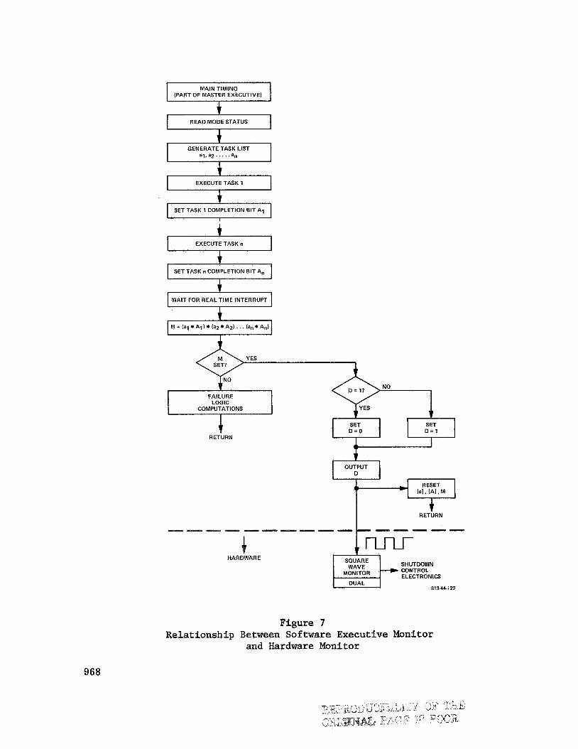
0 Software executive continuously v e r i f i e s t h a t t he required sequence of software t a sks is accomplished each 50 millisecond i t e r a t i o n period
0 External ( t o computer), dual hardware monitors examine the computer's output f o r a required dynamic s igna l p a t t e r n -- any computer f a i l u r e t h a t w i l l prevent the execution of t he spec i f i ed program w i l l cause the pa t t e rn t o cease.
In addi t ion t o the monitoring algorithms, all input s i g n a l da t a are pro- cessed so t h a t a l l redundant con t ro l l a w computations are performed with iden- t ical values f o r all var iab les . H e n c e a l l con t ro l output commands must be iden t i ca l . The servo ac tua to r commands are therefore i d e n t i c a l so t h a t servo system monitoring criteria are dependent only upon servo system tolerance. Some cross-channel (between channel ' l and 2) computation equal iza t ion i s needed, but the amplitude cons t r a in t on the amount of equal iza t ion is a small percent of t h e con t ro l au thor i ty . Cross-channel equal iza t ion is needed t o cor- rect f o r small o f f s e t s caused by an occasional 50-millisecond t i m e skew between da ta used in channel 1 and channel 2.
Computer Executive and Hardware Monitor
Descriptions of t he input s i g n a l screening, monitoring and equal iza t ion algorithms are beyond the scope of t h i s paper. The necessary system concepts can be appreciated as ex t rapola t ions and improvements over techniques used i n contemporary analog systems. However, some a d d i t i o n a l comment i s needed t o e labora te on the concept of a 100 percent, self-monitored computer. A computer system v e r i f i c a t i o n function is used t o generate a prescribed output s i g n a l pa t t e rn a t the end of each i t e r a t i o n cyc le only i f a check l i s t of required
955
computation rout ines has been completely s a t i s f i e d . checking of f t h i s l ist are therefore interwoven throughout t he entire program so t h a t i f any of t h e required rout ines is not properly completed, o r i f a pro- cessor function is f a u l t y , t h e v e r i f i c a t i o n s i g n a l p a t t e r n w i l l no t be properly generated. This v e r i f i c a t i o n s i g n a l i s D/A converted and transmitted t o t h e hardware monitor i n t h e Data Adapter where it is compared with a correct s i g n a l pa t t e rn . A d i f f e rence i n these s i g n a l s w i l l cause the computer complex t o shut down s a f e l y (without servo command t r a n s i e n t s ) . Since t h e v e r i f i c a t i o n s i g n a l is dynamic and must contain co r rec t timing information t o be v a l i d , a f a i l u r e i n the v e r i f i c a t i o n s i g n a l pa th t o the hardware monitor (such as an open o r a hardover) w i l l be detected, as w e l l as timing e r r o r s i n the computer. The com- puter system v e r i f i c a t i o n function serves p r i n c i p a l l y t o de t ec t massive com- puter f a i l u r e s , and does not allow shutdown of p a r t i a l computation functions as is poss ib le with t h e software monitoring functions. Nevertheless, t h e r e is a very qtimate re l a t ionsh ip between the software and hardware monitoring func- t ions. This is shown i n a s impl i f ied representa t ion i n Figure 7. In t h i s f ig - ure the concept of an executive program which generates a task l i s t as a func- t i o n of the s t a t u s l o g i c is i l l u s t r a t e d . With the completion of each of i t s spec i f i ed t a sks , the program acknowledges t h a t it is ready f o r the next task by s e t t i n g a task-completion b i t . When t h e real-time i n t e r r u p t t h a t con t ro l s the program i t e r a t i o n rate occurs, a check ' i s made t o determine whether a l l re- quired t a sks were completed. n i zes a computation f a i l u r e and jumps t o a f a i l u r e response rout ine . It simul- taneously neglec ts t o generate the co r rec t output pa t t e rn . I n t h i s case both the software and hardware monitors w i l l d e t e c t a f a i l u r e , but t h e hardware monitor w i l l requj.re a few cycles of i nco r rec t output before it w i l l respond. For s impl i c i ty , an output p a t t e r n i n the form of a 10 Hz square wave is i l l u s - t r a t e d by Figure 7. I n practice, more complex, mu l t i l eve l pa t t e rns have been used.
The in s t ruc t ions f o r
I f they were no t , t he computer software recog-
Fa i lures of t he d i g i t a l computer's l o g i c c i r c u i t r y assoc ia ted with t h e ex- ecution of s p e c i f i c i n s t ruc t ions w i l l r e s u l t i n t he condition j u s t described. The a i rborne program incorporates techniques which de l ibe ra t e ly exe rc i se the i n s t r u c t i o n r e p e r t o i r e so t h a t f a i l u r e s i n r e p e r t o i r e l o g i c w i l l cause the pro- gram sequence t o ge t l o s t -- t h a t is, the program is forced t o a wrong address. The r e s u l t is a program hang-up o r loop where i t never reaches completion of the spec i f i ed tasks. The program w i l l recognize the real-time i n t e r r u p t , and the machine may be capable of executing shutdown ins t ruc t ions . However, a more fundamental computer f a i l u r e , such as loss of clock o r memory read-write cir- c u i t r y , w i l l leave the computer i n a state where it cannot execute any ins t ruc- t ions . I n t h a t case, t h e hardware monitor w i l l d e t e c t a fixed state on output D r a t h e r than the required dynamic p a t t e r n on output D of t he f igure . It w i l l thereby i n i t i a t e a system shutdown by commanding a computer power-down and in- t e r rup t ion of power t o D/A output commands. computation paths are a l s o used within the computer primarily t o d e t e c t f a i l - ures associated with s ing le-b i t 'malfunctions i n s torage of da t a words. ~
A s mentioned earlier, some dual
956
BACKUP CONCEPTS AND RELIABILITY IMPLICATIONS
Summary of Display/Control Functions
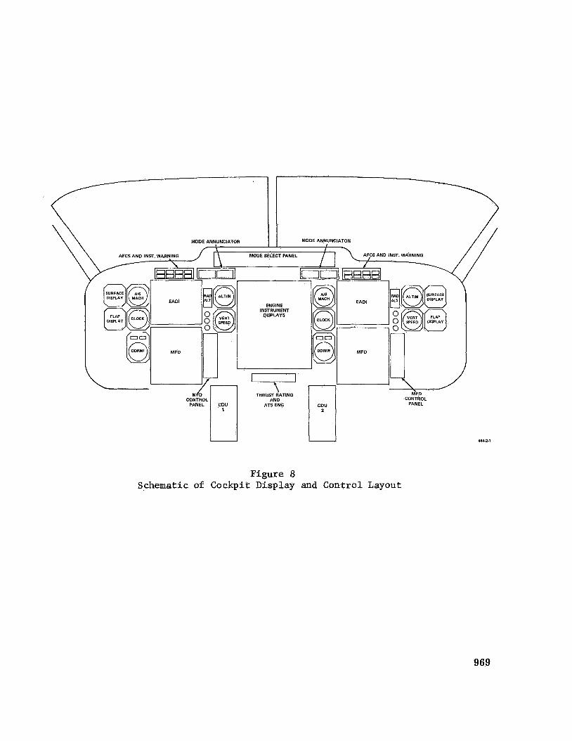
A complete descr ip t ion of t he cockpit d i sp lays and con t ro l s and t h 7 i r in- t e r f aces with t h e redundant computer complex is beyond the scope of t h i s paper. However, it is e s s e n t i a l t h a t the software-controlled functions be i d e n t i f i e d so t h a t we can devise an appropr ia te back-up s t r a t e g y f o r t he remote poss ib i l - i t y of a t o t a l computer shutdown.
Referring t o the highly schematic cockpit layout shown i n Figure 8, con- s i d e r normal system operation with computer complex No. 1 dr iv ing the l e f t set of d i sp lays , and computer complex No. 2 d r iv ing t h e r i g h t set of d i sp lays . The computer/display interconnection may be switched, e i t h e r automatically i n response t o f a i l u r e de tec t ions , o r manually by p i l o t s e l ec t ion . f l i g h t d i sp lays are :
The primary
Multifunction Display
The MFDs primary use is t o serve as an HSI'incorporating a moving-map dis- I n t h i s configuration, i t provides the HSI p i c t o r i a l representa t ion of
The reference path is drawn as a s o l i d l i n e connecting
play. t he f l i g h t s i t u a t i o n with regard t o course, course devia t ion , d i s tance t o des- t i n a t i o n and heading. waypoints. Pro jec t ing from the a i r c r a f t symbol is a trend vec tor depic t ing the a i r c r a f t ' s predicted loca t ion up t o a software s e l e c t a b l e t i m e i n t o ' t h e fu ture . pos i t i on h is tory . Waypoints, a i r p o r t s , airways, landmarks, VORTAC, VOR, VOR/DME s t a t i o n s are normally displayed on the map. the top, with a d i g i t a l readout of a i r c r a f t heading. Scale f a c t o r s e l ec t ion is provided on the MFD con t ro l pane l located t o t h e r i g h t of t he MFD. Scales of 1 , 5, 20 and 80 n a u t i c a l miles-per-inch are provided, but these values are obviously completely under software control. reached, i f t he scale f a c t o r is reduced t o 1.0 n a u t i c a l mile-per-inch, then a runway symbol appears, and a use fu l presenta t ion i n the MLS era when ac- cura te terminal DME and wide-angle azimuth t o t h e landing area is ava i lab le . The MLS accuracy would permit t h e use of t he f i n e scale map so t h a t naviga- t i o n accuracy i s cons i s t en t with map resolution.
Behind the a i r c r a f t is a sequence of do t s representing the previous
The heading tape is a t
When the landing area i s
On the l e f t s i d e of the MFD disp lay area, various parameters assoc ia ted with f l i g h t plan progress and 4-D guidance ( a r r i v a l time) s t a t u s are presented as alphanumeric readouts.
The map is a l s o d isp layable i n the north-up mode (moving a i r c r a f t fixed- map d isp lay) upon s e l e c t i o n a t the MFD con t ro l panel. Slewing con t ro l s move the map up-down and l e f t - r i g h t , wi th the a i r c r a f t symbol remaining f ixed a t i ts t r u e loca t ion on t h e map. Mode se l ec t ion a t the MFI) con t ro l panel permits p i l o t e d i t i n g of t he map content. allow t h e d isp lay t o list pages of da t a , such as t h a t assoc ia ted with rou te planning o r p r e f l i g h t checkl i s t s .
Other mode-select buttons d e l e t e t he map and
957
Elec t ronic Attitude-Director Indica tor
This d i sp lay presents t h e b a s i c horizon presenta t ion v i a instrument i n t e r - f aces t h a t are completely autonomous of t he computer system (not under software cont ro l ) . the upper r i g h t window. Indicated a i r speed appears i n a window a t t h e upper l e f t of t he screen, and the system software provides a choice of which para- meter one can d isp lay i n the window a t the upper center of t he screen. imental work has been done where t h i s window w a s used t o d isp lay d i s t ance t o touchdown (during f i n a l approach) in neares t e 1 n a u t i c a l m i l e , o r vertical speed i n feet-per-minute.
Also independent of software is a d i g i t a l r ad io a l t i t u d e readout i n
Exper-
Other information displayed and r e t r a c t a b l e ( f igu ra t ive ly ) under software con t ro l is l i s t e d :
0 ILS o r F l igh t Path Window
Raw da t a devia t ion from the ILS f l i g h t path o r computed pos i t ion e r r o r from area navigation f l i g h t paths.
0 Fl igh t Path Angle Symbol
0 Fl ight Path Acceleration
0 Fl ight Director Command Bars
0 Fast-Slow Indica t ion
0 Perspective Runway Symbol (This presenta t ion is used when accurate DME information t o t h e landing s i te is a v a i l a b l e , as i n MLS systems.)
On the r i g h t beze l of t h e EADI is a set of approach progress annunciators. Modes t h a t are armed i l lumina te amber, and when engaged they i l lumina te green.
Radio Al t i tude , Al t i tude , Vertical Speed, A i r s p e e d k c h
These ind ica to r s are c lus t e red around t h e AD1 i n the conventional manner.
Autopilot F l igh t Director System Mode Annunciator
The mode annunciator is an e l e c t r o n i c d isp lay containing four alpha- numeric readouts t h a t p resent t he a u t o t h r o t t l e mode, v e r t i c a l guidance mode, lateral guidance mode, and autoland mode. being captured, and i l lumina te steady when the mode i s i n a "track" phase.
These readouts f l a s h i f t he mode is
958
Instrument AFCS/Warning Display
The instrument /AFCS warning d isp lay panel provides f o r annunciation of subsystem f a i l u r e s . of the instrument panel.
A u n i t is loca ted i n the primary viewing area on each s i d e
D u a l D i g i t a l DME and Radio Magnetic Indica tor
To t h e l e f t of t h e MFD is a b a s i c RMI i nd ica to r t h a t has d i r e c t i n t e r f a c e with the rad io receivers and the heading reference systems i n order t o d isp lay bearing t o VOR o r ADF s t a t i o n s . through d i r e c t d i g i t a l i n t e r f a c e s with t h e DME rece ivers .
It a l s o provides dua l d i g i t a l Dm readouts
ATS/EPR Control Display Panel
This panel, loca ted a t the bottom of t h e cen te r instrument panel, serves as the thrus t - ra t ing readout and thrust-mode se l ec to r . It a l s o provides the means of engaging t h e dua l a u t o t h r o t t l e servos. o f f , maximum continuous, climb, c r u i s e o r go-around mode, t he computed EPR l i m i t f o r those modes i s displayed i n conjunction with the t o t a l a i r tempera- tu re . This instrument may a l s o be used t o display t o t a l and s ta t ic a i r temp- e r a t u r e and t r u e airspeed.
By se l ec t ing e i t h e r t h e take-
Mode Select Panel
The Mode Se lec t Panel (MSP) located i n the glare-shielded region provides the following con t ro l and d isp lay capab i l i t y :
0 Dual VHF Nav Receiver frequency readouts ( f o r display of an auto- mat ica l ly tuned s t a t i o n ) o r manual tuning over r ide capab i l i t y -- located on l e f t and r i g h t s i d e of MSP.
0 Speed Control mode select and reference readout (airspeed and Mach via p i t ch o r a u t o t h r o t t l e con t ro l ) .
0 Vertical Guidance mode select and reference readouts. These include f l i g h t path angle and/or v e r t i c a l speed and a l t i t u d e pre-select dis- plays and controls.
o Autopilot and Fl ight Director Engage Switches, including f l i g h t c r i t i ca l engage switches, turbulence mode con t ro l and engage cont ro ls f o r autoland, take-off and go-around.
0 Lateral Guidance mode select and reference read-outs. These in- clude heading and course set con t ro l s and d isp lay redundant navigation sources, p lus means f o r s e l e c t i n g various navigation guidance modes and d isp lays e
959
Dual Control/Display Units (CDUs)
Dual Control/Display Units (CDUs) are shown on the l e f t and r i g h t s i d e of the pedestal . These CDUs are normally used f o r automatic f l i g h t plan s e l e c t i o n and modification. However, t h e i r general purpose keyboard con t ro l s and associ- a ted alphanumeric readout (in conjunction wi th the l a rge da t a display capabil- i t y of t he MFD), allows a convenient man-computer i n t e r f a c e f o r check l i s t a c t i v i t y .
Backup Concepts
The in t eg ra t ed system has many of t he s a m e r e l i a b i l i t y hazards as contem- porary systems. I f a l l a t t i t u d e references f a i l i n f l i g h t , many of t he system functions and modes are disabled. I f a l l of t he NAV receivers f a i l , a d i f f e r - e n t set of functions and modes are disabled. The super ior f a u l t i s o l a t i o n and f a i l u r e assessment c a p a b i l i t y of the in tegra ted system allows automatic recon- f igur ing of t he navigation and guidance functions i n t o a l t e r n a t e o r degraded modes. The c r e w can a l s o p a r t i c i p a t e i n the reconfiguring of the system da ta flow and d isp lays through con t ro l of instrument switching. The fewer black boxes and the improved f a i l u r e de tec t ion , i s o l a t i o n and annunciation capabil- i t y r e s u l t s i n a s i g n i f i c a n t improvement of o v e r a l l avionics r e l i a b i l i t y and u t i l i t y . There is, however, one p o t e n t i a l weakness t h a t d i s tu rbs t h e cr i t ics of av ionics in t eg ra t ion . They c i te the p o s s i b i l i t y of l o s ing a l l av ionics functions as a consequence of los ing one o r two system elements. This crit- i c i s m must be addressed, and the recommended approach must be j u s t i f i e d i n terms of system opera t iona l capab i l i t y i n a l l f a i l u r e s i t u a t i o n s as w e l l as with quan t i t a t ive r e l i a b i l i t y analyses t h a t show o v e r a l l MTBF improvement.
F i r s t i t must be emphatically s t r e s sed t h a t most f a i l u r e s , including mul t ip le f a i l u r e s i n redundant channels, do not wipe out the system. Three questions must be answered. They are:
e What f a i l u r e s can wipe out t he system?
0 What is the p robab i l i t y of such an occurrence?
e What are the backup provisions i n the event of such a f a i l u r e occurrence?
The answer t o the f i r s t question is t h a t the l o s s of both computer com- plexes (Computer and Data Adapter) w i l l d i sab le the e n t i r e system. The pro- j ec t ed MTBFs of the computer and da ta adapter are 5000 hours each. Consider- ing t h a t only one ha l f of s i n g l e da ta adapter f a i l u r e s are t o t a l l y d isab l ing , the p robab i l i t y of t o t a l system l o s s i n a 3-hour f l i g h t , PT( t ) = PF(3) is
Pp (3 hours) = .81 x 10 -6
Making allowances f o r combinations of o the r multiple f a i l u r e s which would cont r ibu te t o a t o t a l system d i s a b i l i t y , it can be s t a t e d t h a t t he p robab i l i t y
960
of t o t a l system shutdown i n a 3-hour f l i g h t is about Suppose we are be- ing overly op t imis t i c on t h e projected MTBF and we only achieve one-half t h e
MTBF values spec i f ied , , o r , making provi-
s ion f o r o ther d i sab l ing f a i l u r e s , t h e p robab i l i t y of t o t a l system shutdown i n
a 3-hour f l i g h t i s about 4 x
-6 Then the PF(3) rises t o 3.24 x 10
(or four shutdowns pe r mi l l ion f l i g h t s ) .
The response t o t h e t h i r d question shows t h a t t h e backup provisions are s u f f i c i e n t t o allow continued instrument f l i g h t (although not t o a C a t . I1 level). The following is a summary of these backup provisions:
0 Both EADIs present horizon d isp lays independent of t h e computers, and the a t t i t u d e re ferences are manually se l ec t ab le from a l t e r n a t e sources.
0 Both DDRMIs present ADF o r VOR bearing ( se l ec t ab le ) and a i r c r a f t heading from s e l e c t a b l e d a t a sources. The VOR r a d i a l s are se l ec t ed through t h e Mode Se lec t Panel course-select knobs which contain course-reference synchros.
0 Provision can be made f o r a d i r e c t i n t e r f a c e between the heading references and the NAV receivers and the MET so t h a t a course l i n e pointing t o t h e azimuth scale would represent t he desired f l i g h t path ( l o c a l i z e r o r VOR r a d i a l ) . The a i r c r a f t symbol would be dis- placed from t h e course l i n e by the course-deviation s igna l . t h e MFD r e v e r t s t o a r e s i d u a l HSI through t h e use of d i r e c t , hard- wired i n t e r f a c e s t o the required sensors.
Thus
0 Manual tuning of NAV receivers is independent of t he computer system. DME d a t a t o two s t a t i o n s is coupled d i r e c t l y from the DME rece ivers t o t h e DME readouts on the DDRMI instruments.
0 Both EADIs present r ad io a l t i t u d e independent of t he computer sys- t e m . Also, t he rad io altimeter display is independent of t he com- puter system.
0 Raw d a t a ILS ( l o c a l i z e r and g l i d e slope devia t ion) is presented on t h e MIS' ILS window symbol. Course deviation from VOR r a d i a l s can a l s o be presented on t h i s d i sp lay i f a course reso lver is in- corporated i n t h e course-set c o n t r o l l e r on the MSP.
a Pneumatic altimeters, a i r speed ind ica to r s and v e r t i c a l speed indi- c a t o r s may be located on the center instrument panel. horizon instrument may a l s o be located on t h i s panel. providing backup a i r d a t a would be t h e use of a low c o s t , mini-air da ta computer having only th ree outputs: a l t i t u d e , a l t i t u d e rate, and airspeed. These t h r e e outputs can be encoded t o provide the word stream needed t o d r ive a l l a i r da t a instruments, following the s e l e c t i o n of t he backup a i r da t a by an appropriate instrument switching arrangement. The backup a i r da t a would a l s o provide the required encoding f o r the a i r c r a f t ' s a l t i tude- repor t ing function.
A self-contained Another means of
961
0 A backup, redundant, hardware yaw damper (with somewhat degraded capa- b i l i t y ) i s included i n t h e f l i g h t con t ro l e l ec t ron ic s . That yaw damper function i s independent of t he computer system.
This leads t o a f i n a l observation regarding l o g i s t i c a l problems, and a very s i g n i f i c a n t departure from contemporary p rac t i ce . It would appear t h a t the consolidation of several f l i g h t - c r i t i c a l functions within an in tegra ted system would n e c e s s i t a t e t he requirement t h a t two computer complexes be des- ignated as r e l i a b i l i t y "dispatch i t e m s " by an operating a i r l i n e . The provis- ioning of spares on a short-haul route s t r u c t u r e would be r e s i s t e d by a i r l i n e maintenance po l i c i e s . Perhaps t h e minimization of t he t o t a l number of black boxes would permit t h e carrying of t h e spares aboard the a i r c r a f t . With ad- vanced f a u l t i s o l a t i o n and maintenance-management techniques inherent i n a sophis t ica ted d i g i t a l system, i t might even be poss ib le t o consider i n - f l i gh t r e p a i r s using the on-board spares.
SOFTWARE SUMMARY AND CONCLUDING COMMENTS
The system design is organized i n t o a software module grouping with a master executive program t h a t i n t e g r a t e s these various modular rout ines and performs such t a sks as timing, system reconfiguring, backup algorithm selec- t i o n , and p a r t of t h e monitoring functions. A list of software modules, t he estimated t i m e per i t e r a t i o n i n an advanced Sperry computer, t y p i c a l i t e r a t i o n rate requirements and memory s torage estimates are given i n Table I. The ad- vanced Sperry computer (designated RMM-1) w a s designed f o r appl ica t ion i n the post-1975 era, and has some extremely high speed and a rch i t ec tu re innovations. Add/subtract t i m e s range from 350 t o 700 nanoseconds and multiply t i m e s , in- cluding memory access ranges from 1.15 microseconds t o 4.2 microseconds ( for a f l o a t i n g poin t multiply). That computer would be provided with a 32K pla ted wire NDRO memory f o r t h i s app l i ca t ion , but Table I shows t h a t t he memory bud- get is only 17,800 words (not including the in t eg ra t ed test and pre- f l igh t check l i s t which would be contained i n the mass memory [ disk] and t r ans fe r r ed t o the computer r e s iden t memory when required). The m a s s s to rage requirement
-6 -6 is estimated as 8 x 10 b i t s f o r worldwide l o g i s t i c da t a , o r 1 x 10 b i t s f o r
reg iona l da t a only. The d i sk capab i l i t y is 10 x b i t s .
A perusual of Table I shows t h a t the advanced computer would be working a t less than 10 percent of i t s ava i l ab le t i m e t o complete the e n t i r e computa- t i o n task. machine (Sperry 1819B) ind ica t e s t h a t t h e e n t i r e task could be done i n 70 per- cent of t h a t machine's ava i l ab le t i m e with memory (main s t o r e ) consumption of about 26K words. Thus the re do not appear t o be any se r ious questions regard- ing whether t he state of t he art i n av ionics can m e e t the requirements of t h i s type of system. That is, can such a software system t h a t encompasses so broad a scope of func- t i ons , t echnica l d i s c i p l i n e s and organiza t iona l r e s p o n s i b i l i t i e s be developed, v e r i f i e d and configuration-controlled i n a t y p i c a l t r anspor t a i r c r a f t develop- ment environment? Fortunately f o r t he author, t h a t question is e a s i l y dodged.
An estimate of t he computer load using a more contemporary 1974
One nagging question p e r s i s t s . Is t h e software manageable?
The answer is no, i f t r ad i t i ona l approaches and relationships between pa r t i c i - pating par t ies (airframe manufacturers, avionics equipment manufacturers and a i r l i nes ) are maintained. survived t o regret slogans such as "there are no problems because i t 's a l l i n the software," w i l l opt imist ical ly answer yes i f the development environment and respons ib i l i t i es can be properly disciplined. t ha t !industry can achieve t h a t organization and d isc ip l ine i n the near future.
However, even those d i g i t a l system pioneers who have
There is pessimism, however,
Figure 1 Candidate 1, Federated Computer System
963
Figure 2
Fail-Operative F l i g h t Control Computer Candidate 2, Dual Navigation Computerization Separate
813-2-23-Rl
Figure 3 Candidate 3, In tegra ted Dual Fail-Operative System
964
\
SENSOR SETS- REDUNDANCY AS REQUIRED
AND CONTROL SENSORS
AIR DATA SENSORS
INERTIAL NAVIGATOR
RADIO N AVA I DS e VOR e DME * 0 MLS e ILS 0 HYPERB
RADIO ALTIMETER
ENGINE AND THROTTLE DATA
/
FLIGHT DATA STORAGE
COMPUTER Q I
* - e SWITCHING LEFT --- FROM D A f A CONTROLS ADAPTER 2 -
DATA ADAPTER
1
I ADAPTER I DATA
REDUNDANT ELECTRO.
HYDRAULIC SURFACE
ACTUATION SYSTEM
2 FROM DATA- ADAPTER 1 RIGHT SWITCHING - c -& CONTROLS DISPLAYS
L
BACK-UP DISPLAYS
BACK-UP DISPLAYS
COMPUTER
FLIGHT DATA STORAGE
813-2.4
Figure 4 Redundancy Architecture
965
CHANNEL
BUFFERED SERIAL LINKS
1' c C
CHANNEL 2
C
la) TRIPLEX -SOFTWARE VOTING
CHANNEL
BUFFERED SERIAL LINKS
1' c C
CHANNEL 2
C
la) TRIPLEX -SOFTWARE VOTING
CHANNEL U I
CHANNEL
U (b) QUADRUPLEX -SOFTWARE VOTfNG
AND AVERAGING
CHANNEL
CHANNEL
BUFFERED SERIAL LINKS
\
BUFFERED SERIAL LINKS
(c) DUAL IN-LINE MONlTORlNG WITH SOFTWARE AVERAGING
81 3-2-6
Figure 5 Redundancy Schemes for Sensors
966
DISPLAYS
DISPLAYS ’ INCLUDES DUAL SENSORS
OR INTERNALLY MONITORED SENSORS WITH VALID DISCRETES 613.7.1
Figure 6 Dual Fail-Operative System Architecture
967
MAIN TIMING (PART OF MASTER EXECUTIVE)
I
a i , a 2 . . . . .an
I EXECUTE TASK 1
4 I SET TASK 1 COMPLETION BIT A i I
EXECUTE TASK n
SET TASK n COMPLETION BIT A,
I WAIT FOR REAL TIME INTERRUPT I
FAILURE LOGIC C COMPUTATIONS
RETURN
SET O = O
NO
$ D = 1 7
HARDWARE SHUTDOWN CONTROL ELECTRONICS
SQUARE
MONITOR I WAVE
DUAL 813-44129
Figure 7 Relationship Between Software Executive Monitor
and Hardware Monitor
968
U U
Figure 8 Schematic of Cockpit Display and Control Layout
444.2.1
969
TABLE I
COMPUTER REQUIREMENTS SUMMARY (BASED ON RMM-1 COMPUTER)
1 t o 20
~ Function
4 , 000
Master Executive
Autopilot/Flight Di rec tor Guidance and S t a b i l i z a t i o n
0 At t i tude S t a b i l i z a t i o n
0 cws 0 Vertical Guidance
0 Lateral Guidance
0 Autoland
0 In t e r locks and Mode Logic
0 Panel Communication
0 Basic Monitoring
Special Fail-Operative Routines
Navigation
0 p , 8 Nav from Navaids
Remote Tuning
0 S t a t e Estimation ( f i l t e r i n g )
0 Fl ight Planning (Waypoint Data Processing, Updating, CDU Communication
A i r Data Computation
Typical Time Per
I t e r a t i o n (P sec)
100
2000
50 t o 700
400
175
Required Memory I t e r a t i o n Storage
(per sec) (words) Requirement
1 t o 20 I 1,000
20 800 2o 800 I
970
TABLE I (cont) COMPUTER REQUIREMENTS SUMMARY (BASED ON RMM-I COMPUTER)
I Function
Autothrottle/Speed Command and Stall Warning (includes cv computation)