The Infant Dom Henrique Bridge over the River Douro, at Porto A. Adão da Fonseca ADÃO DA FONSECA – Consultores de Engenharia, Lda and University of Porto, Faculty of Engineering, Department of Civil Engineering, Porto, Portugal ABSTRACT: The conceptual design of this world record arch bridge and its most significant structural features are presented, together with the construction method, structural control procedures and the most important actions taken during construction. The monitoring system is also described, some in-construction and in-service measurements are given, and basic data on construction materials are provided. 1 INTRODUCTION Porto provides the splendid setting for several world-renowned bridges over the river Douro. The last built is described herein and consists of a shallow and extremely thin arch spanning a distance of 280 m under a stiff box-beam deck (see Figure 1). Figure 1: Westwards lateral view of the completed bridge. The deck is the stabilizing element of the slender arch. This “Maillart” type of arch bridge is a world re- cord and was built by setting up rigid triangular structural systems requiring temporary struts and diagonals to complement those bars provided by the arch and the deck. The equilibrium of the two “half-bridges” cantilevering over the river at a high of more than 70 m was achieved by cable anchorages into the granite slopes, together with concrete-ground struts forming rigid triangular structural systems with deck and tem- porary diagonals. The construction of this bridge was understood to be extremely difficult and quite spectacular, but solutions for unexpected problems were non-existent. Therefore, “state-of-art” monitoring equipment was installed in the bridge and its foundation elements for on line follow up of the construction method and of several imposed settlements, upwards and downwards, introduced into the structure. The structural behaviour of the bridge is numerically controlled and supervised regularly from the design office. Therefore, a complete understanding of reality will ensure timely structural interventions for the re- habilitation of the bridge, if required. Unmistakably, it is a bridge inspired by the works of art designed by the Swiss engineers Robert Maillart and Christian Menn. From the former, the Bridge over the Schwandbach stream is mentioned, built in 1933 and having a span of 37.4 m. From the latter, the Hinterrhine Bridge, in the Viamala Gorge, and the two bridges with a span of 112 m, built in the second half of the twentieth century over the Moesa stream on the south slope of the San Bernardino Pass, are referenced. 2 CONTEXT OF THE PROJECT 2.1 Need for a new bridge The light metro network in the metropolitan area of Porto has its central line connecting the commercial and administrative centres of Porto and Gaia in the upper deck of the Bridge Luiz I. A new bridge for the displaced road traffic had to be built 500 m to the East, halfway in between the Maria Pia Bridge and the
Transcript
The Infant Dom Henrique Bridge over the River Douro, at Porto
A. Adão da Fonseca ADÃO DA FONSECA – Consultores de Engenharia, Lda and University of Porto, Faculty of Engineering, Department of Civil Engineering, Porto, Portugal ABSTRACT: The conceptual design of this world record arch bridge and its most significant structural features are presented, together with the construction method, structural control procedures and the most important actions taken during construction. The monitoring system is also described, some in-construction and in-service measurements are given, and basic data on construction materials are provided.
1 INTRODUCTION
Porto provides the splendid setting for several world-renowned bridges over the river Douro. The last built is described herein and consists of a shallow and extremely thin arch spanning a distance of 280 m under a stiff box-beam deck (see Figure 1).
Figure 1: Westwards lateral view of the completed bridge.
The deck is the stabilizing element of the slender arch. This “Maillart” type of arch bridge is a world re-cord and was built by setting up rigid triangular structural systems requiring temporary struts and diagonals to complement those bars provided by the arch and the deck. The equilibrium of the two “half-bridges” cantilevering over the river at a high of more than 70 m was achieved by cable anchorages into the granite slopes, together with concrete-ground struts forming rigid triangular structural systems with deck and tem-porary diagonals. The construction of this bridge was understood to be extremely difficult and quite spectacular, but solutions for unexpected problems were non-existent. Therefore, “state-of-art” monitoring equipment was installed in the bridge and its foundation elements for on line follow up of the construction method and of several imposed settlements, upwards and downwards, introduced into the structure. The structural behaviour of the bridge is numerically controlled and supervised regularly from the design office. Therefore, a complete understanding of reality will ensure timely structural interventions for the re-habilitation of the bridge, if required. Unmistakably, it is a bridge inspired by the works of art designed by the Swiss engineers Robert Maillart and Christian Menn. From the former, the Bridge over the Schwandbach stream is mentioned, built in 1933 and having a span of 37.4 m. From the latter, the Hinterrhine Bridge, in the Viamala Gorge, and the two bridges with a span of 112 m, built in the second half of the twentieth century over the Moesa stream on the south slope of the San Bernardino Pass, are referenced.
2 CONTEXT OF THE PROJECT
2.1 Need for a new bridge
The light metro network in the metropolitan area of Porto has its central line connecting the commercial and administrative centres of Porto and Gaia in the upper deck of the Bridge Luiz I. A new bridge for the displaced road traffic had to be built 500 m to the East, halfway in between the Maria Pia Bridge and the
932 ARCH’07 – 5th International Conference on Arch Bridges Luiz I Bridge. Therefore, the Infant Bridge takes the centre position between two masterpieces of the 19th Century.
2.2 Tender phase
The public call for tenders for the Design and Build contract of the Infant Henrique Bridge demanded a so-lution that would have to match the technical and aesthetic qualities of those two bridges, which are both considered great works of structural engineering. The responsibility in designing such a bridge was raised further by naming the bridge after the Infant Dom Henrique, the Portuguese Prince who is one of the most distinguished figures of the city of Porto and Por-tugal and who led Europe on the maritime adventure to meet other civilisations. The project designers understood that these qualities would have to appear in a discrete manner, without fanfare and embellishment. A bridge that, without supports on the riverbed, without supports even on the banks of the river, would fly as if it were a bird over the noble waters of the river Douro, with great trans-parency and expressing itself in the purest possible way. This bridge does not contain any decoration. It does not contain anything that does not comply with the functional requirements. Everything in the bridge has a purpose that is both structural and functional. For this reason, it has the virtue of simplicity, structural purity, and geometric regularity (see Figure 2).
Figure 2: Aerial view of Maria Pia, Infant Dom Henrique and Luiz I Bridges.
The Infant Bridge was designed by Structural Engineers A. Adão da Fonseca, F. Millanes Mato and J. A. Fernandez Ordoñez. The first was coordinator of the entire design team during the design and construction phases and member and leader of the design team from AFA - Adão da Fonseca & Associados - Consul-tores de Engenharia, with Structural Engineers R. Bastos, P. Morujão and P. Moás, the second was leader of the design team of Structural Engineers L. Matute, J. Pascual and A. Castellano from IDEAM, and the third was coordinator of the entire design team during the tender phase. The contractor’s consortium was formed by the Portuguese EDIFER - Construções and by the Spanish NECSO Entrecanales Cubiertas (now ACCIONA Infraestructuras). The integration of the bridge in the Fontaínhas platform was designed by Ar-chitect Alexandre Burmester.
3 DESCRIPTION OF THE STRUCTURE
3.1 Conception of the structure
The demand was for a 21st Century Bridge between two bridges of the 19th Century. A bridge with the fol-lowing fundamental conceptual features:
A. Adão da Fonseca 933
- High respect for the river underneath and to the magnificent historic bridges in Porto; it does not com-pete with them; it only tries to come up with a new solution that is discreet in the form and elegant, with the highest technical purity and advanced both in its design and in its construction;
- High respect towards the city of Porto and to its particular profile drawn in the blue or misty sky, with no structural elements above the deck of the Bridge.
The Bridge is located in a well defined urban space that is full of character and personality; this Bridge in-tends to avoid any conflict with the consolidated outline of the city, adding no new elements that might change it. The solution for the Bridge is very simple and neutral towards the city, at the same time calling for an ad-vanced technology in its construction. A Bridge that stays handsomely in its place, showing up very cau-tiously with no will to form either a new image or a new urban deco. This Bridge flies from Gaia to Porto as a bird, in a clean and sensible way and expressing itself in the pur-est manner, with no supports in the river Douro, not even in its banks. This structure flies musically, away from the conventional and from the ornamental. A singular and highly slender arch lands with a natural and harmonious movement in the high rocky slopes up in the hills. The arch supports the deck of the bridge with a profile that is more powerful in its drawing than that of the arch. This Bridge has a peculiar geometric character. It is formed by grand planes (arch and columns) and by the powerful deck box-beam of constant high. The structure is made up of straight lines and planes, not of curved elements. That corresponds better to the anti-funicular of the loading and eases the construction process. This aspect slightly broken is more functional and gives a very special personality to the Bridge [1, 2, 3].
3.2 Design of the structure
The Infant Dom Henrique Bridge is composed of two mutually interacting fundamental elements: a very rigid (slenderness of 1/62.2) prestressed reinforced concrete box beam, 4.50 m in height, supported on a very flexible (slenderness of 1/186.6) reinforced concrete arch, 1.50 m thick. The span between abutments of the arch is 280 m and the rise until the crown of the arch is 25 m, thus with a shallowness ratio greater than 11/1 (see Figure 3). In the 70 m central segment of the bridge, the arch combines with the deck to form a box section that is 6 m in height. The lateral faces of this section are recessed to give the impression of continuity of both the deck and the arch. The arch has a constant thickness and a width that increases linearly from 10 m at the central span segment up to 20 m at the abutments [4].
Figure 3: Elevation and cross-sections of the bridge.
934 ARCH’07 – 5th International Conference on Arch Bridges 3.3 Structural behaviour
The structural behaviour of the flexible arch – rigid deck combination has the following basic features: - Absence of important bending moments in the arch except, due to compatibility with its rigid founda-
tions, at its fixed ends; - Axial force variations carried by the arch are relatively moderate; the tendency of the arch rise to de-
crease due to thermal actions and creep and shrinkage deformations is hindered by the rigidity of the deck;
- The deck behaves as if it were a continuous beam on elastic supports provided by columns spaced 35 m apart (in fact, the contribution of the deck towards resisting the applied vertical loads is around 15% for permanent actions and symmetrical live loads; this percentage increases to 20% in the case of asymmetrical live loads, which means that the usual high bending moments in the arch under live loads with a pressure line not matching the arch shape are avoided);
- Where the arch and deck combine to form the 70 m long central span segment, the eccentricity be-tween the centroid of the arch and the centroid of the box-beam of the deck lets the high compression force arising from the arch to generate localised high negative bending moments that eliminate the positive bending moments along that central span (Figure 4 shows deformed bridge loaded with per-manent actions); thus, a convex curvature in that span that counteracts the deformations that occur in the rest of the structure is guaranteed; however, compatibility at the arch-deck intersections implies an increase of positive bending moments in the spans preceding the central span segment;
- The high compression force introduced by the arch in the central span segment of the deck allows that no prestressing is required in that span after the bridge is finished.
The option for a single box-beam in the 70 m central span, where the arch and deck combine into one sin-gle element, was also an important factor in the optimisation of the structure. In effect, the dead weight of the structure per metre length in this span is close to half of the weight per metre of the structure anywhere else on the bridge, where the arch and deck are separated.
Figure 4: Three-dimensional shell finite element model.
4 PRESTRESSING
The prestressing cables layout is straight for all families of cables, all of which are located in the deck. This was the correct option given the construction process that was adopted (segmental cantilever advance, for both the deck and the arch, the latter following and hanged from the former). The use of maximum nega-tive eccentricity on the prestressing for this construction phase is then recommended, and that requires the cables to be positioned in the upper slab of the deck. This option was also correct in view of the need to oc-cupy the webs with the provisional diagonals of the arch-deck triangulation. There are, therefore, two families of prestressing cables: the "S" family, housed in the upper flange of the box-beam, and the "I” family, housed in the lower flange of the box-beam. The positioning and application of the tension to every cable was meticulously studied in order to control the stresses in the deck during all construction phases.
A. Adão da Fonseca 935 During construction, before closing the arch, negative bending moments are paramount in the beam-box. Thus, the majority of the "S" prestressing cables were placed as the cantilevers advanced. After the arch was closed, the final prestressing was established by extra prestressing cables “S” in the deck above the columns coming from the arch abutments, by extra prestressing cables “I” in the deck spans before the arch-deck intersections, and by taking out all provisional prestressing, including the prestressing cables in the central span. Provisional prestressing was used, always in the upper flange of the box-beam of the deck, in three distinct situations:
- In response to the high negative bending moments above the provisional pillars; - To build the deck spans before the arch-deck intersections by the segmental cantilever method, in
which spans exist the highest positive bending moments in service; - To build the central span of the bridge by the segmental cantilever method, in which span a high com-
pression exists in service. Figure 5 shows that the bending moment diagram in the deck of the bridge constructed by phases (phase accumulation) exhibits a translation towards negative moments in comparison with the equivalent moments existing in the same structure built on total temporary supports.
-600000
-500000
-400000
-300000
-200000
-100000
0
100000
200000
300000
4000000 35 70 105 140 175 210 245 280 315 350 385
x (m)bend
ing
mom
ent (
kNm
)
construction on temporary supports
phased construction
Figure 5: Comparison of the bending moment diagrams.
At first sight, this difference is especially inconvenient in the central span of the structure, where the high compression provided by the arch generates very high negative bending moments. The lower flange of the box-beam could then be subject to compression stresses that would not be admissible, and the “centralisa-tion” of that compression force cannot be achieved through prestressing, since prestressing is not very effi-cient in reducing compression stresses in tubular cross-sections. On the contrary, hyperstatic effects of prestressing may successfully reduce compression stresses, since the hyperstatic effects generate important flexural forces together with negligible axial forces. Figure 6 shows the influence coefficient diagram of one of the cross-sections (next to the arch-deck inter-section) of the central span in which the negative bending moment is at its maximum. Identification of the most effective prestressing cables in controlling stresses in those same cross-sections is then evident. In re-lation to prestressing in the lower flange, favourable stresses are induced by hyperstatic effects of prestress-ing forces introduced, after the arch and deck were finished, between columns M3 or M4 and the corre-sponding arch-deck intersections. In addition, the removal of temporary construction prestressing forces in the upper flange of the central span of the bridge generates significant hyperstatic moments that are highly favourable. Therein, the objective of reducing the negative bending moments in the central span of the bridge is achieved by adding those two effects.
936 ARCH’07 – 5th International Conference on Arch Bridges
-800
-600
-400
-200
0
200
400
600
800
1000
1200
0 35 70 105 140 175 210 245 280 315 350 385
x (m)
'' (kN
m/1
000k
Nm
)
Figure 6: Coefficient of influence at node 42 of the central span.
* The coefficient of influence (η’’M) of cross-section j upon cross-section i is the hyperstatic bending mo-ment (M) in cross-section i due to a prestressing force (P) of unit value applied with a eccentricity (e) of unit value along an element of unit length in cross-section j. Thus, the total hyperstatic bending moment in cross-section i due to a constant prestressing force P along length L is given by (1):
( ) ( )∫ η′′=L
M dxxexPM0
... (1)
5 ARCH-DECK INTERSECTIONS
5.1 Design and detail
The design and detailing of the arch-deck intersections (see Figure 7) were initially studied using a strut-and-tie model applied to all different combinations of forces possible to be transferred through those inter-sections. Then, the design was tested on a precise model of three-dimensional finite elements (with ANSYS software [5]) that basically confirmed the results of the strut-and-tie model used.
Figure 7: Detail of the arch-deck intersection.
Another aspect checked with the same three-dimensional model was the relative stiffness of the intersec-tions. Results were compared with those of the bar model used for the general calculation of internal forces in the structure, in which a single node for each intersection transferred the eccentric axial force of the arch to the deck. It was later verified that the effects of lower stiffness of the model of finite elements, that logi-cally materialised a smoother transmission, did not significantly affect the structure general internal forces and remained on the safety side of the local discontinuity zone.
A. Adão da Fonseca 937 5.2 Transmission mechanism at the arc-deck node
At the arch-deck union, the eccentricity between the arch axis and the box girder axis on the 70 m central span (see Figure 8) imposes an important negative bending moment (around 520000 kNm for dead loads) that eliminates the positive bending on the central span (see Figure 5). Furthermore, due to the high axial force transmitted by the arch, no tension stresses appear on the central span under the most unfavourable action combination, eliminating completely the need for prestressing at this span.
N2
α N3
M3
M1
M2
Figure 8: Relative position of element axes and equilibrated stress-resultants at arch-deck union.
On the other hand, compatibility with the adjacent zones of the deck (outside the central span) considerably increases positive bending on those zones. For the smooth transfer of forces across the arch-deck intersection, a strut-diaphragm S (see Figure 9) was introduced and the flow of forces is as follows:
- Compression in the upper flange of the deck is reduced from N1s to N2s, with N1s > N2s; therefore, part of the compression force in the upper flange of the deck is transferred to the webs and to strut S;
- Compression force N2i in the lower flange of the deck is lower than the difference between compres-sion force N3 cos(α) in the arch and tensile force N1i in the lower flange of the deck, that is, N2i < N3 cos(α) - N1i; this signifies that some forces in the lower flange are transferred to the webs and to strut S;
- Webs are under tension before the arch-deck intersection and are under compression after it, and that is due to the transfer of forces from both the upper and lower flanges.
N2s
N2A
N2i
N1s
N1A
N1i
N3 M3
Figure 9: Internal forces converging in the arch-deck interaction.
6 INSTABILITY OF THE ARCH
Geometric and mechanical non-linear analysis of the structure in Ultimate Limit State (ULS) was essential to be performed because of the severe shallowness of the arch and its high mechanical slenderness. That was carried out according to the general non-linear method provided by the Eurocodes and the CEB-FIP Model 90 Code [6]. The step by step calculation was developed under increasing loads and under effects of geometric and mechanical non-linearity of both arch and deck, including the interaction with the time-dependent effects of creep and shrinkage, previously considered as linear when using the visco-elastic model. An initial geometric imperfection of 8.75 cm (≅ effective length/300 and homothetic to the arch buckling mode) was introduced (see Figure 10) and superimposed to the time-dependent bending effects of the arch self-weight (≅ 4.5 cm at infinite time). The step by step analysis under increasing loads showed that the creep effects reduced significantly the instability (failure) load of the arch, to occur at the centre of the sec-ond span. It was also confirmed that, at ULS, the stiffness of the deck guarantees the practical immobility of the arch nodes under the columns, and that allows the stability study to be performed on the simplified model of an equivalent column with 3 spans of 35 m and with fixed ends.
s
938 ARCH’07 – 5th International Conference on Arch Bridges
δ1
δ2
δ3
Arch buckling mode Equivalent column
Figure 10: Models for stability studies of the arch.
This model was analysed using the PYRUS [7] software, with sensitivity analysis being performed to study the effect of variations in values of the following parameters: creep and shrinkage coefficients, equivalent imperfections, compressive strength of concrete and reinforcement layout at critical sections. Design was optimised to equalize the failure load due to instability of the various spans and thus to maximize the buck-ling safety factor of the arch. At collapse, the arch deflection was 18.8 cm, which is approximately 1.42 times the deflection of first order due to dead loads and imperfections, including time dependent effects. Therefore, non-linear phenomena were relatively moderate. Failure mechanism was due to over compression of the concrete.
7 PARTICULARITIES OF ITS REALIZATION
7.1 Construction method
An arch that is so shallow and so slender can only function structurally if in conjunction with the deck. The construction method was to progress by cantilevering the deck and the arch from each side of the river. In the tender phase, it was proposed to construct temporary piers with cables staying both the arch and the deck (see Figure 11), although it was recognized to be illogical to build first a cable stayed bridge to be later transformed into an arch bridge.
Figure 11: Construction method at tender phase.
Once the design was awarded, the construction method was revised and the solution described herein was adopted. That is, “only one bridge” was built [8]. Two temporary pillars were built first in order to reduce the span from 280 m to 210 m, during construc-tion, and trusses were created by adding tensile diagonal bars (provided by temporary stays) and vertical compression bars (provided by the reinforced concrete columns and temporary steel struts) between the arch and the deck [8]. Therefore, two cantilevering trusses of considerable height were constructed. The 70 m central span was built by the cast-in-place segmental box-beam construction method (see Figure 12).
A. Adão da Fonseca 939
Figure 12: Three phases of the construction method.
Trusses were created similarly in the slopes outside the arch (see Figure 13). They were defined by the deck, abutments, columns, reinforced concrete struts built on the ground and working integrally with foot-ings and rock foundation, and diagonals provided by temporary stays. When the cantilevered trusses pro-gressed over the river, those “outside” trusses took to footings the high longitudinal tensile forces develop-ing in the deck cross-sections located above the provisional pillars. Diagonals in “outside” trusses worked also as backstays, ensuring that the two bridge halves were tied back to the deck abutments during con-struction.
Figure 13: Construction structural system on the side of Porto.
940 ARCH’07 – 5th International Conference on Arch Bridges Tensile forces in all diagonals were applied and regulated in a predefined order to control the structural re-sponse of the two cantilever trusses. Global equilibrium of each “half bridge” under construction was secured by inclined ground anchorages and by footings connected together by reinforced concrete struts. Geometries of these footings (see Figures 14 and 15) were optimized in order to mobilize the rock foundation in resisting the horizontal components of the construction forces, which meant that forces generated in footing struts were kept under control and stability of the rock slopes was ensured. This ground-structure interaction was studied extensively in an elastoplastic finite element model with Mohr-Coulomb behaviour, demonstrating that a significant altera-tion to the direction of the lines of force acting on all footings was possible during construction.
Figure 14: Backstays, ground struts, and anchorages on the Gaia side of the river.
The deck above the slopes outside the arch was built on traditional scaffolding. Pairs of advancing form-works for the deck and the arch were used only after columns M1 and its symmetrical M6 (see Figures 14 and 15) were built.
Figure 15: Longitudinal cross-section of the finished bridge before provisional elements were dismantled.
Slenderness of the arch required stays or suspension bars from the rigid and powerful deck to be installed during construction (Figure 16), and axial compression in the arch had to be generated before bending moments due to self-weight could be resisted. Indeed, one, major advantage of the adopted construction method was the gradual introduction of compression in the arch and its foundations by the truss system, al-lowing creep effects to take place gradually and to be better controlled and compensated.
Figure 16: Stays and suspension bars for the arch.
A. Adão da Fonseca 941 After columns M2 (see Figure 17) and M5 (on the Porto side, symmetrical to M2) were built, predefined upwards forces of 9000 kN were introduced at the top of those columns by sets of hydraulic jacks (see Fig-ure 21a) and predefined forces of 5000 kN were introduced at the top of the provisional pillars by other sets of hydraulic jacks (see Figure 21c). These forces produced positive bending moments reducing the nega-tive moments generated previously by the segmental cantilever method at the deck cross-section above col-umns M1 and M6 and at the arch spring cross-sections. Construction of both deck and arch progressed from columns M2 and M5 until 20 m of cantilever spans were built. At this stage, provisional struts MP1 (see Figure 17) and MP6 (on the Porto side, symmetrical to MP1) were positioned and corresponding diagonals D1 and D8 were tensioned to initiate the truss be-haviour of each “half bridge”.
a) b)
Figure 17: a) D1 - provisional diagonal and MP1 - provisional strut; b) D2 - provisional diagonal.
This procedure was repeated for each triangular element of the advancing trusses. At predefined instants, tensile forces in relevant diagonals and backstays were adjusted to control internal forces and displace-ments generated in the two “half bridges”. These adjustments were determined by analytic calculation of the evolving hyperstatic system set up in the axial force influence matrix of all active bars (diagonals and backstays), as explained in Chapter 9. Between column M3 (see Figures 17b and 15) and the arch-deck intersection, two provisional struts MP2 and MP3 were positioned in order to define diagonals D3 and D4 with efficient inclination. Symmetrically, provisional struts MP5 and MP4 and diagonals D6 and D5 were installed between column M4 (on the Porto side, symmetrical to M3) and the corresponding arch-deck intersection. Figure 18 shows the bridge in an advanced stage of its construction. When construction of the two central 35 m cantilever spans was half-way, a downwards settlement of 25 mm was introduced on top of both pro-visional pillars. These settlements had been programmed at design stage and envisaged a convenient redis-tribution of internal forces before closing the bridge.
Figure 18: Construction stage in January 2002.
After the two “half bridges” were united by the crown segment (see Figure 19), backstays, diagonals, pro-visional struts and pillars were all dismantled obeying to a specified sequence [8].
942 ARCH’07 – 5th International Conference on Arch Bridges
Figure 19: General view of the bridge before provisional elements were dismantled.
7.2 Construction innovation
Several techniques and procedures used in the construction of the Infant Henrique Bridge were highly in-novative. Moreover, to build a large bridge subject to a geometrical precision criteria never before de-manded was, in itself, an enormous challenge for the contractor. Also, the erection of an extremely slender and shallow arch over the distance of 280 m lead to the construction of the deck ahead of the “suspended” arch, which is a method that had been used only once before, with the Nakatanigawa Bridge in Japan, where the arch spans 100 m and rises 19 m. From the construction of the Infant Henrique Bridge, the following application examples are noted:
- The segmental cantilever method of construction of both the deck and the arch was performed with a very ingenious double formwork traveller (see Figure 20) allowing the simultaneous execution of the arch and deck segments; the positioning of the support platform for the arch formwork was adjusted to the millimetre before the concrete of each segment of the arch was poured, and was carried out using two automatic and computerized hydraulic systems; this operation became very difficult when the dis-tance between arch and deck reduced as they approached the arch-deck intersections; moreover, all that was implemented with extremely tight geometric tolerances;
Figure 20: Double formwork traveller and automatic computerized system.
- The monitoring of the structural behaviour of the bridge during construction was carried out by cen-tralized computer systems (see Figure 21b) that collected data from relevant structural elements of the bridge and that automatically stored, managed, and processed these data in order to interpret readings supplied by the internal monitoring devices;
- The special operations of predefined upwards and downwards settlements (see Figures 21a and 21c) on top of columns M2 and M5 and on top of provisional pillars, in order to move the internal forces along the deck, as well as the release of the bridge from those temporary pillars, were controlled by those computer systems, with on-line follow up of readings in the internal monitoring devices;
A. Adão da Fonseca 943
a) Jacks on top of column M2; b) Centralized computer system; c) Jacks on top of provisional pillars Figure 21: Equipment for special construction operations.
- The removal of the temporary pillars weighing 7800 kN was achieved by means of a rotation and transfer system with on-line control and adjustment of forces in the hydraulic jacks that suspended the rotation axis located halfway up the pillar (see Figure 22).
Figure 22: Removal of the temporary pillar on the Porto side of the bridge.
7.3 Comparison between construction methods
If the structural solution of the bridge is audacious, then it is no surprise that its construction was difficult and complex. This would be the case no matter what construction method was adopted. Amongst the many possibilities studied, it was concluded that the construction process used was the most suitable for a num-ber of reasons, among which the following are emphasized:
- With the construction method used, the rock layers under the arch springs were compressed gradually as the construction advanced. The resulting advantages are evident. This reason is so important that alone could justify the decision taken.
- With the construction method used, the arch was gradually compressed as the construction advanced, which allowed for compensation of its elastic shortening and for reduction of shrinkage and creep ef-fects. Therefore, the arch functioned just the way it was designed right from the start of its construc-tion, that is, under compression. Internal forces were introduced gradually, as shown in Table 1 for the “half bridge” on the Gaia side of the river.
Table 1: Evolution of the axial forces in the arch spring cross-section of the Gaia side. Phase Axial force (kN)
On reaching column M2 12280 On reaching column M3 29770 On reaching the arch-deck intersection 174470 After uniting the two “half bridges” 269280 After removing all backstays, diagonals and arch suspension bars 278650
944 ARCH’07 – 5th International Conference on Arch Bridges
- With the construction method used, the highest compression force in the arch occurred when the di-agonals were removed, therefore when the structure was fully built, with a small increase in that force from the instant the arch was closed. On the contrary, the temporary cable stayed method proposed at tender stage would have implied the transfer of most of the total axial force of 278650 kN with the re-lease of the stays. Such a sudden application of force to the arch would certainly not be a good solu-tion, especially in relation to an arch as slender as this one.
- The construction method of temporary cables staying the arch bridge would add the uncertainties re-sulting from hyperstatic redistribution of thermal effects between the concrete bridge and stays to the complexity of the geometric control; in such a case, there would be a greater risk of error in the com-putation of internal forces and stresses in the deck.
- With the adopted construction method, internal forces in the deck, arch, diagonals, and struts are much less susceptible to redistribution, which, it should be underlined, is difficult to evaluate and control.
- With stays from provisional towers, during construction both the arch and the deck would be dead-weight supported by the stays and not performing any structural function. That is not the case with the implemented construction method, which is thus a lot more efficient.
8 STRUCTURAL ADJUSTMENT
8.1 Adjustment forces in active bars
The adjustment of internal forces in active bars (backstays and diagonals) meant the modification of inter-nal forces and displacements generated in the structure. It is important to note that once the internal forces and displacements are "compensated" up to any con-struction phase, through forces applied in active bars in previous phases, variations of the forces in active bars for the next construction phase were dependant only upon forces and/or displacements at that same phase. This is true but for the effects of the rheological behaviour of concrete, which were not relevant dur-ing the construction phases. Therefore, “compensated” variation values from all previous phases add up to “compensated” accumulated values (internal forces and displacements) at each phase. During construction, it has already been stated that the deck carries out the function of tension flange of the trusses. However, it should be added that each “half deck” under construction was “fixed” to the abutment in order to avoid any horizontal displacement of the “half deck” until the two “half bridges” were united at the centre. Advantage was taken from the flexural rigidity of the abutments, which were greater than the axial rigidity of the backstays. Therefore, deck abutments withstood flexural moments in order to balance the remaining axial force developed in each “half deck”. But with the successive adjustments to the forces acting on the backstays, the flexural moment in the corresponding abutment was also subject to variation, either because the advancing cantilever was generating an increase of the axial force in the deck or because backstays forces were increased and thus were balancing more of the axial force in the deck. Notwithstand-ing, flexural moments in each abutment were always towards the slope because backstays were always pulling the “half deck” towards the abutment. Distinctly, the only function of the adjustment of the forces acting on diagonals was to control the flexural forces on the deck, simultaneously modifying its displacements. The objective was to compensate the nega-tive bending moments resulting from the cantilever construction, thus avoiding higher negative moments in the deck.
8.2 Analytical calculation of adjustment forces
Internal forces produced by the gravitational loads applied in each construction phase were calculated for that phase. Forces corresponding to an imposed deformation on each one of the active bars (backstays and diagonals) were also calculated. Forces at each phase were then linear combinations of all previous forces. The combination coefficients were determined by imposing as many conditions as there are active bars in that phase, as explained in 8.3. To explain the need for this procedure, the effect of casting the concrete in the deck and arch between the last provisional struts (MP4 and MP5) and their corresponding arch-deck intersections is taken as an exam-ple. Figure 23 displays the bending moment and vertical displacement diagrams in the deck with and with-out adjustment of forces in the active bars.
A. Adão da Fonseca 945 Therefore, the successive application of gravitational loads in all construction phases generated internal forces and displacements that were “compensated” by the adjustment of forces installed in the “active bars”.
Bridge deck-150000
-100000
-50000
0
50000
1000000 35 70 105 140 175 210 245 280 315 350 385
x (m)
bend
ing
mom
ent (
kNm
)
with adjustmentwithout adjustment
Bridge deck
-250
-200
-150
-100
-50
0
50
100
0 35 70 105 140 175 210 245 280 315 350 385
x (m)
verti
cal d
ispl
acem
ent (
mm
)
with adjustmentwithout adjustment
a) b)
Figure 23: a) Bending moment diagrams b) Vertical displacement diagrams.
8.3 Formulation of the adjustment of tension in the active bars
The adjustment of forces applied by active bars was carried out according to an internal force criterion, for which the following equations were established:
j
n
ii
Tiji
ppj bxff
1∑=
=+ or
=
×
+
m
n
Timn
Tim
Tin
Ti
ppm
pp
b
b
x
x
ff
ff
f
f 1
1
1
1111
(2)
where n - number of active bars (bars to be post-tensioned) m - number of bars of the tension adjustment structural model (>n)
n+1 - number of load cases of the tension adjustment structural model for i - load case i
Case 1 – applied gravitational loads; Case 2 – applied force in active bar 1; ... ; Case n+1 – applied force in active bar n
ppjf - force in bar j due to applied gravitational loads
Tijif - force in bar j due to the tensioning of active bar i
ix - scale factor, or combination coefficient, affecting the load case corresponding to the post-tensioning of active bar i
jb - value (null or not) of force in bar j
Imposing values in n lines of vector bj (m×1), the combination factors xi (n×1) of the load cases referring to the application of tension to the active bars were calculated. The force applied in each active bar i results from the multiplication of factor xi by the force generated in that bar in the load case corresponding to its tensioning.
Applied force on active bar i = iTi
ki xf
946 ARCH’07 – 5th International Conference on Arch Bridges where k is the corresponding line to active bar i in the influence matrix (2). The adjustment force, that is, the variation of the internal force acting in active bar i at the end of each phase does depend on its applied force and on the response of that same bar to the tensioning of all the other active bars.
Adjustment force in active bar i = ∑=
n
ii
Tiji xf
1
Finally, the internal force generated in a general bar (active or not) j at the end of each phase is given by
Final force in general bar j = j
n
ii
Tiji
ppj bxff =+∑
=1
The vertical displacements of all the nodes q of the structure are obtained in the same way:
q
n
ii
Tiqi
ppq uxuu
1∑=
=+
where ppqu - vertical displacement of node q due to applied gravitational loads Tiqiu - vertical displacement of node q due to the tensioning of active bar i
ix - scale factor, or combination coefficient, affecting the load case corresponding to the post-tensioning of active bar i
qu - final value of the vertical displacement at node q
9 MATHEMATICAL MODELS IN THE ANALYSIS OF THE CONSTRUCTION PROCESS
9.1 Evolutive analysis
First, a linear elastic analysis of the bridge was carried out using the software ROBOT [9] to calculate forces acting on backstays and diagonals at every construction phase of the bridge. This analysis allowed the design of all structural elements of the bridge, as well as the fine-tuning of the construction process. The criterion for the adjustment of forces installed in the active bars is expressed in the influence matrix described in 8.3. Strict limits on bending moments in the abutments and the maximization of deck length under positive flexural action were the adjustment restrictions. With these forces applied in active bars, in-stantaneous deformations in every construction phase were also determined. Afterwards, two evolutive calculations were performed, apart from one another, which consider the time-dependent behaviour of concrete through the correct modelling of the viscous-elastic properties of materials. These mathematical models were coded into the DIFEV [10] and FASES [11] softwares, both confirming the results of the adjustment criterion used in the linear elastic model. The calculation with the DIFEV software considered 58 phases. This model is less detailed than the model implemented with the FASES software, where more than 1000 phases were defined, with all execution steps inherent to the execution of each segment of every structural element introduced separately. The modelling of the viscous-elastic behaviour of concrete is different in the two softwares – DIFEV follows the MC78 (additive model) [12] and FASES follows the MC90 (multiplicative model) [6]. This difference provides an evaluation of the sensibility of the structure to long-term effects, necessarily distinct in the two models. Parallel to the FASES evolutive model, a linear elastic model incorporating all steps and construction phases considered in the FASES code was developed with ROBOT. This model was used to generate the influence matrices of the active bars, step by step, and provided the countercheck of the FASES model out-put. It provided also the analysis of the responsiveness of the bridge at any construction step with respect to any alteration in the geometry or in the applied forces and to the effects of differential thermal variations.
9.2 Geometric control criteria
The geometric control criteria for the construction of the Infant Dom Henrique Bridge were the following: - Geometric conditions of the road:
i) Grade line of the road;
A. Adão da Fonseca 947
- Geometric conditions related to structural behaviour: ii) Resistant configuration of the bridge as a whole, in particular the rise of the arch and its angles
of deviation under the columns, given that any loss in rise would decrease the structural effi-ciency of such a slender arch and, in the event of major deviations, would generate non-negligible second order effects;
iii) The shape of the arch, which was built with cambers distant from the fundamental buckling modes in order to obtain additional safety factors in relation to instability caused by the bend-ing of such a slender and heavily compressed element.
Geometric corrections introduced into the structure are “instantaneous actions”, but decision on the value of any geometric correction was always provided by an evolutive calculation. Thereafter, values of actions (modification of forces in diagonals) to be implemented in order to achieve that correction were obtained from the influence matrices referring to that instant, that is, with linear elastic behaviour for the reinforced concrete, for which knowledge of the values of the elasticity modules of the concrete at that instant was re-quired. Therefore, decisions on any correction and on corresponding actions to be implemented were based on analyses performed with both linear elastic and evolutive mathematical models, but, as construction pro-gressed, those models were updated with data that was collected continuously from the bridge internal and external monitoring system. Moreover, corrections modified the construction sequence defined in the evolutive mathematical models; therefore, the new sequence had to be introduced into those models and only at the end of the evolutive analyses of the modified models, when all provisional structural elements are disassembled, effects of that particular intervention could be fully evaluated. Total shrinkage and total creep of the concrete are considered to take place at 20000 days of age of the bridge. Therefore, the intended final geometry for the bridge was established at that age and time-dependent effects incorporated in the evolutive mathematical model were then considered in defining the construction geometry of each segment of the bridge. It must be mentioned that redistributions of stresses due to change in the resistant structural system were less important than those resulting from difference in age of the concrete of distinct structural elements.
10 CONTROL OF THE CONSTRUCTION
10.1 Geometric control
Structural efficiency of the Infant Bridge both at construction phase and at service phase demanded a very strict control of all parameters. In particular, geometric conditions ii) and iii) in 8.3 were detailed with the utmost care. For example, the arch was built with cambers distant from the fundamental buckling modes, as indicated in Figure 24. These cambers had to be constructed with maximum precision (see Figures 25), where the curves “designed” and “real” are shown) and high performance concrete (C60/75) was used for the first time in Portugal.
δ1
δ2
δ3
δ1,t∞ = 0,10 m δ2,t∞ = 0,15 m δ3,t∞ = 0,10 m
Figure 24: Definition of the cambers of each half arch
948 ARCH’07 – 5th International Conference on Arch Bridges
0
0.01
0.02
0.03
0.04
0.05
0.06
0.07
0.08
70 75 80 85 90 95 100 105
camber (design)camber (real)
0
0.02
0.04
0.06
0.08
0.1
0.12
0.14
0.16
0.18
105 110 115 120 125 130 135 140
camber (design)camber (real)
0
0.02
0.04
0.06
0.08
0.1
0.12
140 145 150 155 160 165 170 175
camber (design)camber (real)
Figure 25: Comparison between the designed and real cambers.
10.2 Monitoring during construction
Construction of this bridge was a major achievement requiring a highly efficient monitoring system [2, 13, 14], capable of assessing physical quantities of different types, namely support reactions, axial forces, bending moments, rotations and temperatures at particular sections of the arch, deck and provisional struts and pillars, and axial forces in the temporary stay cables (backstays and diagonals). The monitoring of the construction of the bridge was performed by three separate instrumentation systems, one for the granite slopes on each side of the river, another for the foundations and another for the concrete elements and temporary stay cables (see Figure 26).
Figure 26: Monitoring system implemented during construction.
A. Adão da Fonseca 949 10.2.1 Instrumentation of the rock slopes and foundations
A total of 14 inclinometers, going 40 m deep into the granite slopes on both sides of the river (9 on the Porto side and 5 on the Gaia side), were installed. In addition, inside the old tunnel located near the footing of the arch on the Porto slope, three transverse sections were monitored with optic convergence systems, as shown in Figure 27.
Figure 27: Optic convergence system in the old tunnel (chords 1-2, 1-3 and 2-3).
In both sides of the bridge, a total of 11 ground anchorages were provided with load cells (7 in the Porto side and 4 in the Gaia side). Figure 28 shows the graphical evolution of the forces in the monitored ground anchorages of the Porto abutment of the deck.
Figure 28: Location and evolution of forces in monitored ground anchorages in the Porto side.
10.2.2 Internal instrumentation of the superstructure
The internal instrumentation of the bridge superstructure was especially important [2, 14]. It was controlled by two computer systems that were located inside the box-beam of the bridge (one in each “half bridge”). They worked independently, and collected data were transmitted by modem to other workstations (in the construction yard office, in the supervisory agents’ office, in the designers’ offices – AFA, in Porto, and IDEAM, in Madrid – and in Kinesia - Ingeniería de Auscultación Company, who were in charge of the sys-tem). The system provided details on a number of different parameters, such as reactions in supports and bending moments, axial stresses, rotations, and temperatures in selected sections of the arch, deck, columns
950 ARCH’07 – 5th International Conference on Arch Bridges and provisional struts and pillars. A total of 120 sensors were installed (strain gauges, tiltmeters, ther-mometers and load cells), as indicated in Figure 29 and Table 2.
Figure 29: Location of the sections containing instrumentation in the Gaia “half bridge”.
Table 2: Sensors in the Gaia “half bridge” Section Sensor Type of measurement
1 Load measuring bearings Axial force in deck
2 Tiltmeters Thermometers
Rotation of deck and column, mean curvature of deck (bending moment) Temperature of deck upper and lower slabs
3 Tiltmeters Strain gauges
Rotation of deck, mean curvature of deck (bending moment) Axial force and bending moment in deck
4 Strain gauges Thermometers
Axial force and bending moment in deck Temperature of deck upper and lower slabs
5 Strain gauges Axial force and bending moment in deck 6 Strain gauges Axial force and bending moment in column 7 Strain gauges Axial force and bending moment in column 8 Strain gauges Axial force and bending moment in arch
9 Strain gauges Thermometers
Axial force and bending moment in arch Temperature of arch upper and lower fibre
10 Strain gauges Axial force and bending moment in arch 11 Strain gauges Axial force and bending moment in arch
12 Strain gauges Thermometers
Axial force and bending moment in provisional pillar Temperature in opposing faces of the provisional pillar
10.2.2.1 Adjustment of the structural behaviour models
The system incorporates an “intelligent” statistical correlation module that allows adjustments to readings of sensors and variation intervals of the thermal environmental parameters and mechanical properties of structural materials (creep, shrinkage and elasticity module). That feature was most helpful for the design team when controlling and interpreting data provided by the system. Typical difficulties associated with the deterministic reading of that data were overcome and statistic methods were used to obtain reliable and “mechanically meaningful” measurements that could be compared with values established at design stage, thus supporting a rapid decision-making process. Another important feature is the capacity to “identify” parameters of the mechanical behaviour of the bridge. For example, creep of the actual structural concrete cast in the bridge could be “measured”. Figure 30 shows correlation between readings from one strain gauge at the base of column M1 (see Figure 14) with readings from one thermometer inside the concrete. The upper right hand graph in Figure 30 dis-plays that correlation incorporating automatically the effects of the rheological behaviour of the concrete and the loading history of the structure.
A. Adão da Fonseca 951
Figure 30: Example of statistical processing of data provided by monitoring sensors.
10.2.2.2 Identification of the need for structural corrective operations
Figure 31 provides an example of readings from the monitoring system that lead to a “structural correc-tion”. Graphs show the development of strains in the upper and lower fibres of the spring cross section of the arch on the Porto side. The arch is clamped to the abutment and the progressive “gap” between the readings on the two fibres signifies negative bending moment at that section was increasing, because of in-sufficient tension applied to the suspension stay cables during the construction of the first span of the arch. This situation was corrected by re-tensioning the stays before the provisional pillar became a support for the advancing structure.
g
X: auto, Y: c12 - s train gage (upper fibre)X: auto, Y: c15 - s train gage ( lower fibre)
17N/mm²
-3230-04-01 07:00 27-07-01 09:00
12
7
2
-3
-8
-12
-17
-22
-27
Figure 31: Development of strains in the upper and lower fibres of the spring cross section of the arch.
952 ARCH’07 – 5th International Conference on Arch Bridges 10.2.2.3 Follow up of the structural response during special operations
The construction method involved several special operations defined at design stage. The first consisted in the application of predefined upwards forces at the top of columns M2 and M5 and at the top of the provi-sional pillars, as explained before. Mention was also made to the second operation of downwards settle-ments introduced on top of both provisional pillars when the two cantilevers of the central span were half-way in their construction. This process involved the implementation of very precise and controlled partial settlements with the help of hydraulic jacks with a total capacity of 100000 kN for each side. Another spe-cial operation took place at the end of the construction of the bridge, when supports provided by the provi-sional pillars to the closed bridge were taken away simultaneously on both sides of the river. Arch and deck above those provisional pillars descended 95 mm in this extremely delicate operation. An operation con-trolled in real time by the monitoring system, which provided the continuous checking of data in relation to expected values, previously calculated. Figure 32 shows the comparison between expected and measured values for the upper and lower fibres of the deck cross section above the provisional pillar on the Porto side, during the jacking operation.
Figure 32: Strains in the deck cross section above the Porto provisional pillar.
-80
-60
-40
-20
0
20
40
60
80
100
-10 0 10 20 30 40 50 60 70 80 90 100 110
Vertical displacement of the deck above the Porto provisional pillar (mm)
A. Adão da Fonseca 953 10.2.2.4 Follow up of the structural response during load testing
The structural response of the bridge during load testing was monitored directly and instantaneously for a variety of load cases of both static and dynamic nature. As an example, Figure 33 shows the “measured values” of the lines of influence of strains in the upper and lower fibres of three cross sections of the deck, obtained with the passing of four 30 ton trucks with a con-stant speed of 5 km/h. In this figure, the high level of precision and reliability of the readings can be confirmed.
Figure 33: Lines of influence of strains in three cross sections of the deck.
10.2.3 Monitoring of forces in provisional stay cables
A large number of sensors would be required for direct measure of tensile forces on all provisional stays (backstays and diagonals). Moreover, load cells or other permanent devices are very expensive and thus it was decided to measure cable forces indirectly from their vibration frequency, according to the vibration chord theory [15]. An independent team from the Porto Faculty of Engineering performed that job with portable equipment. On average, a weekly campaign involving 10 to 20 stays was carried out [13]. Freyssinet C-Range system cables with multiple 15.7 mm diameter parallel strands were used in all suspen-sion stays of the arch, diagonals and backstays. Strands were sheathed individually to secure their durabil-ity during construction. The number of strands in each cable was 37 in diagonals and backstays, and from 9 to 15 in suspension stays of the arch. Cables were pulled to 60% of fptk, always from the deck. Length of individual cables varies from 12 to 52 m. Indirect estimation of the cable tension through measurement of the corresponding vibration frequencies, combined with the use of portable equipment, has proved to be an accurate, simple, and rapid form of analysis for the majority of stay cables.
10.2.3.1 Equipment and test procedures
Measurement of cable natural frequencies was performed by a high sensitivity piezoelectric accelerometer with a magnetic base attached to the stay cable, as shown in Figure 34. A portable Fourier Analyser based on a laptop and a PCMCIA card collected the pre-amplified ambient vibration signal and provided average power spectral density estimates using 6 to 10 time records, each with an approximate length of 40 s.
954 ARCH’07 – 5th International Conference on Arch Bridges
a) b)
Figure 34: a) View of instrumented cables b) Measurement of vibration on a suspension cable of the arch
Figure 35 shows the average spectral estimates of the ambient response of one suspension cable of the arch during two distinct stages of tensioning. The marked peaks are representative of the cable harmonics, cor-responding natural frequencies showing an increase that is associated with an increase of axial force, in line with the vibration chord theory. Since the tension estimate depends on the value of these single frequen-cies, an adequate frequency resolution is required in order to minimize the error associated with the tension estimate. This was achieved by a selective choice of the sampling rate. For the present case, this rate could vary from 19.3 to 250 Hz, producing an error in the tension estimate of less than 1%.
Figure 35: Average spectral estimates of the ambient response of one suspension cable of the arch during two distinct
stages of tensioning.
10.2.3.2 Results
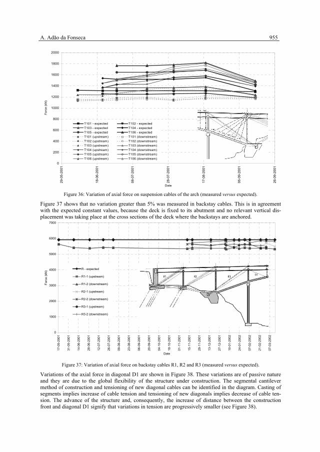
Figures 36, 37 and 38 display the evolution of axial forces in some suspension cables of the arch, backstays and diagonals, respectively. Additional curves shown in those figures refer to the expected variation of the same forces obtained from the mathematical models at the relevant construction stages of the bridge. If relevant construction operations are considered in the analysis of these figures, good agreement is found between measured and expected forces. Discrepancies that were identified were also present in the moni-toring system of the deck and arch, and they were explained by occasional deviations at the site from the construction schedule. For example, axial forces in suspension stays T104, T105 and T106 in Figure 36 increased at every con-crete casting operation until 18-08-2001. The weight of the reinforced concrete was to be balanced by ade-quate tensioning of each pair of new stays, with minor modification of tensile forces in stays previously in-stalled. Because new stays were tensioned to lower values, previous stays were taken an extra burden. As explained before, pairs of strain gauges in the arch also detected a progressive bending of the arch (see Figure 31) and the subsequent re-tensioning of stays was implemented.
Figure 36: Variation of axial force on suspension cables of the arch (measured versus expected).
Figure 37 shows that no variation greater than 5% was measured in backstay cables. This is in agreement with the expected constant values, because the deck is fixed to its abutment and no relevant vertical dis-placement was taking place at the cross sections of the deck where the backstays are anchored.
0
1000
2000
3000
4000
5000
6000
7000
17-0
5-20
01
31-0
5-20
01
14-0
6-20
01
28-0
6-20
01
12-0
7-20
01
26-0
7-20
01
09-0
8-20
01
23-0
8-20
01
06-0
9-20
01
20-0
9-20
01
04-1
0-20
01
18-1
0-20
01
01-1
1-20
01
15-1
1-20
01
29-1
1-20
01
13-1
2-20
01
27-1
2-20
01
10-0
1-20
02
24-0
1-20
02
07-0
2-20
02
21-0
2-20
02
07-0
3-20
02
Date
Forc
e (k
N) R - expected
R1-1 (upstream)
R1-2 (downstream)
R2-1 (upstream)
R2-2 (downstream)
R3-1 (upstream)
R3-2 (downstream)
Figure 37: Variation of axial force on backstay cables R1, R2 and R3 (measured versus expected).
Variations of the axial force in diagonal D1 are shown in Figure 38. These variations are of passive nature and they are due to the global flexibility of the structure under construction. The segmental cantilever method of construction and tensioning of new diagonal cables can be identified in the diagram. Casting of segments implies increase of cable tension and tensioning of new diagonals implies decrease of cable ten-sion. The advance of the structure and, consequently, the increase of distance between the construction front and diagonal D1 signify that variations in tension are progressively smaller (see Figure 38).
956 ARCH’07 – 5th International Conference on Arch Bridges
0
1000
2000
3000
4000
5000
6000
700008
-11-
2001
15-1
1-20
01
22-1
1-20
01
29-1
1-20
01
06-1
2-20
01
13-1
2-20
01
20-1
2-20
01
27-1
2-20
01
03-0
1-20
02
10-0
1-20
02
17-0
1-20
02
24-0
1-20
02
31-0
1-20
02
07-0
2-20
02
14-0
2-20
02
21-0
2-20
02
28-0
2-20
02
07-0
3-20
02
Date
Forc
e (k
N)
D1 - expected
D1-1 (upstream)
D1-2 (downstream)
Figure 38: Variation of axial force on diagonal cable D1 (measured versus expected).
Topographic campaigns during construction of the bridge were most important and a wide range of correla-tions were made, controlling the entire construction process in geometrical terms and providing reliable and counterchecked data for decisions to be taken, as explained before.
11 CONTROL OF THE BRIDGE IN SERVICE
11.1 Internal monitoring
The internal monitoring system used during construction was kept operative and is now following up the structural behaviour of the bridge during its lifetime. Continuous information about the “in situ” time-dependent effects of the cast concrete is provided and associated redistributions of internal forces are iden-tified through readings in sensors. The methodology of analysis of the measured data includes the identification of the section deformation due to temperature variations and the statistical evaluation of the rheological properties of concrete, as it was made during construction. For example, the prediction of creep and shrinkage of concrete is always very difficult design phase because it is associated with the variability of many parameters, namely those depending of the local environmental conditions. The monitoring system will permit the identification of the time-dependent behaviour of the bridge and its contrast with the assumptions made during the design phase. Figure 39 shows, for the first year of service of the bridge, the comparison between the expected and meas-ured values of stresses in the reinforcement at the central cross section of the bridge.
Figure 39: Stresses in the reinforcement bars at the central cross section of the bridge (expected versus measured).
11.2 Topographic survey
Figure 40 shows the deck vertical deflection due to the time-dependent behaviour of concrete between No-vember 2002 and March 2007 (approximately 4.5 years). The deformed shape is similar to the expected theoretical values obtained with the visco-elastic model of the bridge, but the maximum deflection (about 10 cm) is smaller than the expected value (about 13 cm). Thermal effects (higher temperature in March 2007 than in November 2002) may explain this difference.
Identical deformed shapes confirm that the bridge global structural behaviour is very consistent with the mathematical model used. Smaller values for the displacements may indicate that the time-dependent ef-fects are less important than it was assumed in the visco-elastic model.
Figure 40: Deck vertical deflection (expected versus measured).
958 ARCH’07 – 5th International Conference on Arch Bridges 12 STRUCTURAL MATERIALS
A total of 26373 m3 of concrete was required for the construction of the Infant Henrique Bridge, as shown in Table 3.
Table 3: Concrete consumption Class Structural element Quantity (m3)
C25/30 Bridge footings and ground struts 10380 Footings of provisional pillars 378 Abutments and column P1 2420 C30/37 Bridge deck over Fontaínhas platform 441
C35/45 Columns M1 to M6 1234 Bridge deck (except central 70 m span) 5700
C50/60 Provisional pillars 606 Arch 4126
C60/75 Central 70 m bridge span 1088
Total consumption of steel was - Passive steel 3800 t - Prestressing steel 660 t
Concrete volume in the bridge deck is 0.8 m3 per m2 of deck. Passive reinforcement in the deck is 220 kg of steel per m3 of concrete, or 176 kg per m2 of deck. In the arch, 270 kg of passive reinforcement are used per m3 of concrete. This high steel percentage results from the high mechanical slenderness of the arch (λ=81) and from the need to control instability in the highly compressed arch. It is especially relevant to provide the composition of concrete C60/70, as follows:
- Cement I-52, 5R 460 kg - Microsilica (Meyco MS610) 40 kg - Sand 730 kg - Gravel 1 750 kg - Gravel 2 300 kg - Water 155 kg - High-range water-reducing admixture (Glenium 52) (6 litres) 8,4 kg - water / cement 0,31
13 CONCLUSION
The Infant Dom Henrique Bridge exhibits high technical and aesthetic qualities and represents an important technological advance in construction; both because of the magnitude of its dimensions and because of the following set of relevant facts (see Figure 41):
- It is the second largest concrete arch in Europe; with a span L = 280 m, it is only surpassed by the Krk Bridge, in Croatia, constructed in 1979 and which, with a 390 m span, held the world record for 18 years, up to 1997;
- It holds the world record for shallow deck stiffened arches; with a constant thickness of 1,50 m (ap-proximately L/187), it stands out for being extremely slender in relation to the usual thicknesses used in conventional rigid arch solutions (between L/40 and L/60);
- The rise of f = 25 m means a shallowness (L/f = 11,2) for the arch that has no parallel in the field of large span arch bridges;
- Its “static coefficient” (L2/f > 3000), which is directly proportional to the axial force existing at the crown of the arch, is the largest of any concrete arch built to date.
A. Adão da Fonseca 959
×=
fLpH
2
8
Figure 41: Structural response of a “perfect arch”.
In fact, this arch is the most loaded and the most “delicate” (see Figure 42) in the world. Notwithstanding the fact that it is a world record holder for slenderness, it possesses the greatest axial force of any concrete arch.
Figure 42: Underneath view of the Infant Dom Henrique Bridge arch.
The Infant Dom Henrique Bridge was awarded a Special Mention as Outstanding Structure – 2006 by fib - Fédération International du Béton. Construction of the bridge started on 2nd January 2000, closing of the arch (and deck) took place on 21st June 2002, and structural works were finished in September 2003. Opening to traffic came only on 30th March 2003, when road accesses to the bridge were also open. Total cost of the bridge was just under 15 millions euros (referred to 2003).
14 ACKNOWLEDGEMENTS
Acknowledgements are due first to J. A. Fernandez Ordoñez, unfortunately dead before construction of the Infant Dom Henrique started. His enthusiastic response to my invitation to coordinate the design team in the tender phase of a very demanding competition and our common vision of the “correct” bridge to stand in between the two masterpieces of the 19th Century was fundamental for the success of the our idea. Ac-knowledgements are also due to all colleagues at AFA and at IDEAM for their contributions to the discus-sions in which many of the final solutions were found, but quality and reliability of the audacious design and secure follow-up of the daring construction of the bridge is credited to the expertise, scientific knowl-edge and dedication of my companion F. Millanes Mato and of the brilliant young engineers R. Bastos and L. Matute.
960 ARCH’07 – 5th International Conference on Arch Bridges 15 REFERENCES 1. Adão da Fonseca, A.; Millanes Mato, F., “Infant Henrique Bridge over the River Douro, Porto”, SEI,
Journal of the International Association for Bridge and Structural Engineering (IABSE), Vol. 15, Nº 2, May 2005: 85-87.
2. Adão da Fonseca, A., “Ponte Infante D. Henrique”, Congresso Nacional da Engenharia de Estruturas 2002 – Os novos desafios na qualidade das obras, [Infant Dom Henrique Bridge, 2002 National Con-gress of Engineering and Structures – New quality challenges for works] Lisbon, July 2002: 725-744.
3. Millanes Mato, F.; Adão da Fonseca, A., “Proyecto y construcción del puente arco Don Henrique sobre el Duero en Oporto”, Jornadas sobre La Vida de los Puente, Donostia – San Sebastián, April 2005: 373-391
4. Adão da Fonseca, A. et al, “Ponte Infante D. Henrique, dimensionamento estrutural”, Encontro Na-cional de Betão Estrutural 2000 [Infant Dom Henrique Bridge, structural dimensioning, 2000 Struc-tural Concrete National Meeting], Porto, Nov. 2000: 857-865.
5. ANSYS Structural, ANSYS, Inc., Pa, USA, 2000. 6. CEB-FIP Model Code 1990, Thomas Telford, 1993. 7. PYRUS-2, “Reinforced concrete columns”, Cubus Engineering Software, Zurich, 2000. 8. Adão da Fonseca, A. et al, “Ponte Infante D. Henrique, processo construtivo”, Encontro Nacional de
Betão Estrutural 2000 [Infant Dom Henrique Bridge, construction process, 2000 Structural Concrete National Meeting], Porto, Nov 2000: 867-877.
and systems”, ASCE Journal of Structural Division, Vol. 115, No. 10, October 1989. 11. Sérgio Cruz, J., “Controlo da fase construtiva de pontes atirantadas” [Construction control of cable-
stayed bridges], Dissertation for doctorate – IST-UTL, 1997. 12. CEB-FIP Model Code for Concrete Structures, 1978. 13. Adão da Fonseca, A. et al, “Monitoring of temporary cables in Infant Dom Henrique Bridge”, First
European Workshop on Structural Health Monitoring, Paris, July 2002: 1065-1070. 14. Adão da Fonseca, A. et al, 2004. “Monitorização em fase de serviço do comportamento estrutural da
Ponte Infante D. Henrique”, Encontro Nacional de Betão Estrutural 2004 [Monitoring of the structural behaviour the Infant Dom Henrique Bridge in service], Porto, Nov. 2004: 865-872.
15. Irvine, H., Cable Structures, MIT Press, 1981, ISBN 0-262-09023-6.