Abstract: Geological difficulties may have a high impact on the economics of an underground constructionproject, especially when the chosen excavation system turns out to be unsuitable for the conditionsencountered. Thus it can be argued that the geological and petrological characteristics of the rock mass shouldbe evaluated with the same degree of effort as that for the geotechnical prognosis. Mechanical parameters seemto be of limited value, especially if the rock mass is composed of anisotropic and inhomogeneous material.Inhomogeneity and anisotropy obviously play a key role during the process of rock fragmentation. The mainsubject of this paper is the investigation of the influence of anisotropy in drill and blast tunnelling.
To investigate the crack pattern in different rock types, drilling tests have been performed using drilling rigswith state-of-the-art percussion drills and common hard metal button bits. The base of the drill hole in the blockhas been extracted and orientated thin sections have been analyzed. Using the Particle Flow Code, the influenceof anisotropy on crack propagation has been investigated. First results show similar crack patterns andpropagation as found in the drilling tests.
Résumé: Des difficultés d’ordre géologique peuvent avoir un impact important sur la situation économiqued’un projet de construction souterraine. Particulièrement lorsque la méthode de fouille choisie s’avère ne pasêtre la bonne pour les conditions rencontrées. Ainsi on peut conclure que les caractéristiques géologiques etpétrologiques d’un bloc de pierre devraient être évaluées avec le même soin que les tests géotechniques. Lesparamètres mécaniques particulièrement semblent être de valeur limitée si le bloc de pierre est composé dematériaux non homogènes et anisotropes. L’hétérogénéité ainsi que l’anisotropie jouent visiblement un rôleprimordial au cours du processus de fragmentation de la roche. Le sujet principal de cet article traite des étudessur l’influence de l’anisotropie sur le forage et le perçage de galerie souterraine.
Afin d’étudier les modèles de fente dans différents types de roche, des tests de forage ont été exécutés àl’aide de disques de forage, de percussion derniers cris et de « boutons de fleuret » communs en métal dur. Labase du trou de forage dans le bloc de pierre a été extraite et de fines sections orientées ont été analysées.L’influence de l’anisotropie sur la propagation des fentes a été étudiée en utilisant le « Particle Flow Code ».Les premiers résultats montrent des modèles de fente ainsi qu’une propagation de la fente similaires à ceuxtrouvés dans les tests de forage.
ROTARY PERCUSSIVE DRILLING IN UNDERGROUND CONSTRUCTIONFor drilling blastholes in hard rock, today the rotary percussive drilling is standard in underground mining and
tunnelling, providing maximum performance under most circumstances. The hydraulic drill hammer is a combinationof a rotary drilling machine and a percussive drill and uses a separate rotary and percussive mechanism.
Whereas percussive drilling is controlled by jerkily moving of the drilling rod with only a loose contact of thedrilling bit to the bottom of the borehole, rotary percussive drilling is characterized by continuous rotation -comparable to rotary drilling. By means of high feed pressure (12 - 20 kN), the drilling bit is always tight to thebottom of the borehole. Since the torque is much greater, crushing work is also carried out by shearing between theimpacts.
Regarding just the procedure, rotary percussive drilling is superior to both rotary drilling and percussive drilling.The hydraulics facilitates an optimum energy transfer from the percussive mechanism to the drilling rod. Parametersare the technical specifications of the drill hammer, flushing system and the design of the drilling bit. An illustrationof the whole system is given in Figure 1.
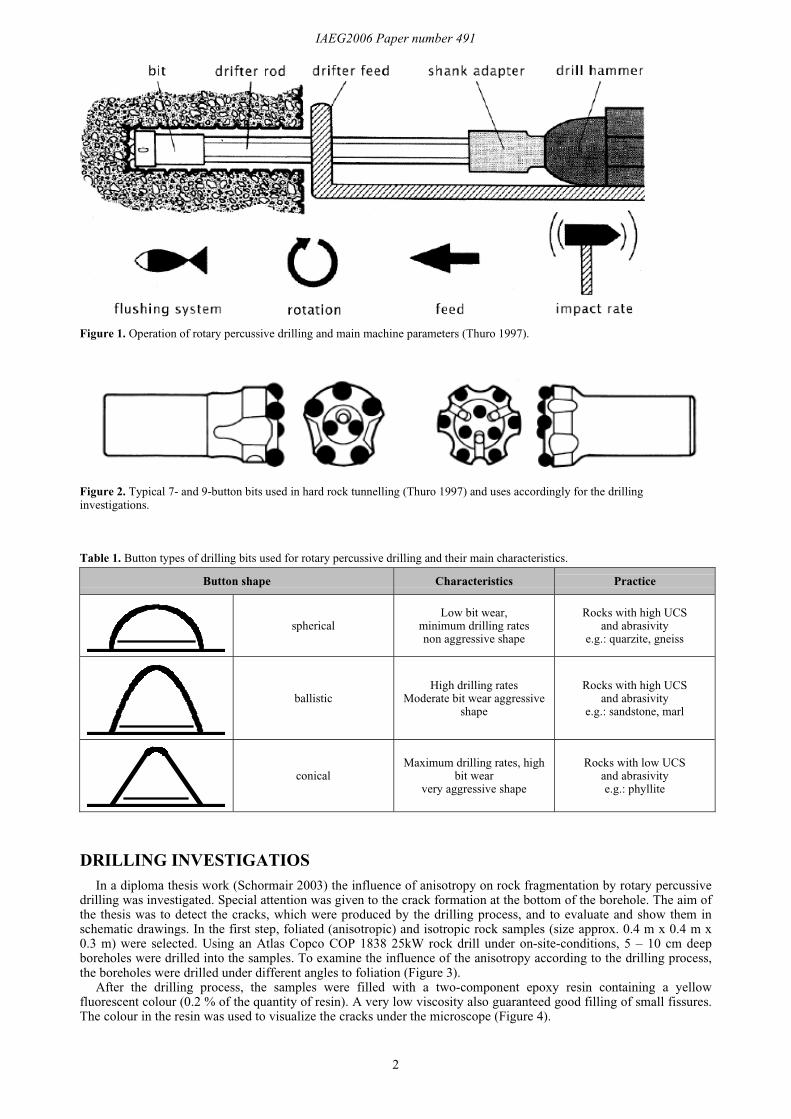
Figure 2 shows typical button bits used in underground excavation in rotary percussive drill rigs. The drilling bit isthe part of the rig that carries out the crushing work. The bit consists of a carrier holding the actual drilling tools:buttons of hard metal (tungsten carbide with a cobalt binder, MOHS´ hardness 9½). Possible arrangements of buttontypes and their main characteristics are shown in Table 1. The shape of the button and the design of the bit (geometryand arrangement of buttons, flush holes and draining channels) have a strong influence on bit wear and drillingperformance. Common drilling bits contain six to nine buttons whereas the diameter ranges from 32 to 48 mm.
Typical tunnelling rigs consist of a diesel-hydraulic rubber-wheeled tramming carrier, carrying up to three boomswith hydraulic drifter feeds and rock drills. The range comprises units for hydraulic drilling with a selection ofdifferent carriers, booms, feeds, and rock drills.
IAEG2006 Paper number 491
2
Figure 1. Operation of rotary percussive drilling and main machine parameters (Thuro 1997).
Figure 2. Typical 7- and 9-button bits used in hard rock tunnelling (Thuro 1997) and uses accordingly for the drillinginvestigations.
Table 1. Button types of drilling bits used for rotary percussive drilling and their main characteristics.
Button shape Characteristics Practice
sphericalLow bit wear,
minimum drilling ratesnon aggressive shape
Rocks with high UCSand abrasivity
e.g.: quarzite, gneiss
ballisticHigh drilling rates
Moderate bit wear aggressiveshape
Rocks with high UCSand abrasivity
e.g.: sandstone, marl
conicalMaximum drilling rates, high
bit wearvery aggressive shape
Rocks with low UCSand abrasivitye.g.: phyllite
DRILLING INVESTIGATIOSIn a diploma thesis work (Schormair 2003) the influence of anisotropy on rock fragmentation by rotary percussive
drilling was investigated. Special attention was given to the crack formation at the bottom of the borehole. The aim ofthe thesis was to detect the cracks, which were produced by the drilling process, and to evaluate and show them inschematic drawings. In the first step, foliated (anisotropic) and isotropic rock samples (size approx. 0.4 m x 0.4 m x0.3 m) were selected. Using an Atlas Copco COP 1838 25kW rock drill under on-site-conditions, 5 – 10 cm deepboreholes were drilled into the samples. To examine the influence of the anisotropy according to the drilling process,the boreholes were drilled under different angles to foliation (Figure 3).
After the drilling process, the samples were filled with a two-component epoxy resin containing a yellowfluorescent colour (0.2 % of the quantity of resin). A very low viscosity also guaranteed good filling of small fissures.The colour in the resin was used to visualize the cracks under the microscope (Figure 4).
IAEG2006 Paper number 491
3
Figure 3. Procedure: formatted and drilled rock sample (left), drilling process (right).
A series of thin slices were taken from the bottom of the borehole (Figure 4). Table 2 and Table 3 show resultsfrom the mineral analysis and the calculation of the equivalent quartz content of an isotropic diorite sample and ananisotropic granite-mylonite sample.
Table 2. Average mineral content, Rosival abrasiveness and equivalent quartz content of the diorite.
plagioclase 8 25 2,00pyrite <1 55 0,55Sum 100 Sum 57,04
The main task was to detect the crack patterns. After examining the patterns, the results were shown in schematicdrawings. Subsequently, some important rock properties, especially the unconfined compressive strength, thedestruction work and the Young´s modulus, were determined. To understand the rock fragmentation process at the
IAEG2006 Paper number 491
4
bottom of the borehole it is important to analyze macroscopic and microscopic cracks. The results of both an isotropicand an anisotropic sample are given below.
Crack pattern in isotropic rock samplesIn the diorite sample cracks range from 0 – 20 mm length with an average of 5 mm (Figure 5). No macroscopic
cracks are visible. All cracks run nearly parallel to the surface. Pyroxenes, plagioclase, biotite and microcline aremainly divided by cracks that do not follow the mineral cleavage. Also cracks formed along the grain boundaries areonly rarely seen. Only some pyroxenes show cracks along cleavage or grain boundaries. It seems that tectonicallybased cracks from the prehistory of the rock or zones of weakness become activated by the mechanical stress of thedrilling process. There is no opening of the grain structure from the power of the hammer and no grains were rippedout. All the cracks develop from the bottom of the hole and are therefore produced by the drilling process. The cracksreach down to 0.5-1.5 mm under the bottom of the borehole. Surface-parallel cracks which have no contact with thebottom (no resin in the cracks) may be opened and propogated further with additional beats from the drill hammer. Inthe sidewalls of the borehole, cracks develop in very much the same way as described in the bottom.
Figure 5. Thin section of the diorite with the cracks traced in red colour.
Crack pattern in anisotropic rock samples: normal to foliationThe anisotropic samples were drilled at different angles to foliation. Cracks of macroscopic and microscopic scale
are distinguished below, which could be seen in the drilled rock samples and in the thin sections.
Macroscopic crack patternIn the sample different macroscopic cracks can be seen. There are big cracks parallel to foliation, which are
running normal to the sidewalls of the borehole reaching up to 40 mm into the sample. Also visible are small cracks,which are oriented parallel to the bottom of the borehole. They reach down to 5 mm under the bottom. Cracks runningslanting to the foliation down to 20 mm into the specimen can rarely be detected.
Microscopic crack patternIn the thin sections most of the cracks run parallel to the bottom of the borehole thus parallel to foliation (Figure 6).
The cracks nearly always use lanes of mica, which are zones of weakness in the rock sample. Cracks across mineralcomponents, like quartz, feldspar or biotite can rarely be detected. Stair-like fissures use the shortest distance betweenmica-rich layers. An opening of mica layers is visible which may be performed by the rotary, and therefore shearing,action of the drill. These large cracks allow large fragments to be removed by the flushing.
Cracks can be found on the sidewalls of the borehole, which run normal to the hole as well as parallel to thebottom. The normal cracks along mica layers reach up to 40 mm into the rock. The cracks, which are running parallelto the sidewalls of the borehole go across the mineral components and only rarely use cleavage or zones of weakness.No opening of the grain structure or tearing out of mineral components along grain boundaries can be seen. Cracks,which are running normal to the bottom of the borehole, are rarely found. They are produced by stress duringpercussion. Cracks slanting to the mica layers were found very rarely.
IAEG2006 Paper number 491
5
Figure 6. Thin section of the granite-mylonite sample. Drilling direction normal to foliation, cracks traced in red colour.
Crack patterns in anisotropic rock samples: slanting to foliation
Macroscopic crack patternTypical large cracks in coarse-grained rock types (syenite) are oriented normal to the bottom of the borehole, not in
the foliation. They cut up to 60 mm deep into the rock. Cracks running 20 mm along the foliation are rarely seen. Inthe fine-grained, very tight foliated granite-mylonite no cracks in the macroscopic size could be found.
Microscopic crack patternIn the thin sections, a correlation of the crack patterns between the spacing of the foliation and the grain size could
be detected. In the very tight foliated, fine-grained granite-mylonite, the cracks run along the mica layers as zones ofweakness (Figure 7). Cracks across mineral components are rarely found since they are not zone of weakness. At thebottom of the borehole a roof-shaped or stair-like structure of the crack patterns could be detected. The opening of themica layers seems to be caused by the percussive process and the shearing process of the bit caused the breakout ofthe fragments. An angle of about 15 degrees seems to be useful to break out the fragments. In the widely foliatedcoarse-grained syenite, cracks parallel to the surface are common. Cleavage of mica and feldspar as zones ofweakness are rarely used. The cracks don’t follow the foliation as a zone of weakness. Often cracks occur acrossmineral components, which are oriented parallel to the bottom of the borehole. Cracks normal to the bottom areproduced by the percussion energy of the hammer. They have already been detected as macroscopic cracks.
Figure 7. Thin section of the granite-mylonite sample. Drilling direction slanting to foliation, cracks traced in red colour.
Crack patterns in anisotropic rock samples: parallel to foliation
Macroscopic crack patternWhen drilling parallel to foliation, cracks mainly develop in the foliation and not parallel to the borehole bottom.
Cracks of up to 50 mm could be observed. Also cracks in the edges of the bottom could be detected running up to30mm into the rock sample.
IAEG2006 Paper number 491
6
Microscopic crack patternThe small cracks run parallel to the surface (normal to the foliation). The cracks develop through all mineral
components. Focusing on the fragments (chips), mechanical stress caused by shearing could not be detected. Theywere broken out without any movement along the bottom of the borehole. It seems that the percussion drill caused avery high stress state between the buttons, which is high enough to tear out the chip. In those only 1 mm sized crackscould be found, which are parallel to the foliation. They were evidently caused by a previous percussion processseconds before. Cracks parallel to foliation are common since they use mica layers as zones of weakness spreadingdown to 10 mm into the sample (Figure 8). Macroscopic cracks range up to 50 mm as described above. Cracksparallel to the sidewalls of the borehole could rarely be detected, but those that were are probably remnants of theprevious percussive action seconds before.
Figure 8. Thin section of the granite-mylonite sample. Drilling direction parallel to foliation. Cracks traced in red colour.
SUMMARIZING THE CRACK PATTERNSThe generalized crack patterns are presented in Figure 9. The three anisotropic cases are distinguished as well as
the isotropic case.
Macroscopic crack patternsKnowing that drilling performance is best normal to foliation and worst parallel, the macroscopic crack patterns
support the following statements:When the direction of drilling is normal to the orientation of foliation, rock material is compressed normal but
sheared parallel to it. Although cracks will develop radial to compression, the cracks parallel to the bottom of theborehole will be used for chipping. Usually in this case the highest drilling velocities are obtained because of thefavourable schist orientation. Drilling is controlled by the shear strength of the foliated rock material. This causeslarge sized chips and a maximum drilling performance.
If the drilling axis is oriented parallel to foliation, compression is also parallel to foliation but shear stress is normalto it. Less and smaller cracks (observed 1 mm) develop for reasons of higher strength normal to the weakness planes.Drilling is controlled by the tensile strength parallel to the foliation producing small sized fragments and minimumdrilling performance.
Generally, drilling is controlled by the dip angle of foliation, submitting medium sized fragments during thecrushing process. Drilling performance is - by geometrical reasons - mainly a cosine function of the dip angle. In theparallel case, rock properties are the highest and drilling rates are low. In addition blasting conditions are often relatedwith drilling. Therefore, if the tunnel axis is parallel to the main foliation, drilling and blasting conditions are expectedto be very poor.
Microscopic crack patternsIn the thin sections, there seems to be a relationship between the crack pattern and the direction and condition of
the foliation. The crack pattern in the widely foliated quartz-syenite sometimes propagates along the mica layers, but itis not compelling. The cracks develop parallel to the surface and use foliation only if the foliation runs along asurface-parallel crack. Mostly they propagate across mineral components. The crack pattern is similar to those fromisotropic rocks. In the granite-mylonite samples, the spacing and the condition of the foliation is important. It ispostulated that the better the condition of the foliation (clear mica layers) and the closer the foliation is, the more thecracks run along the mica layers in the microscopic scale. This means that the mica layers were almost exclusivelyused as zones of weakness from which cracks developed.
The above confirms that the degree of anisotropy plays a key role in rock fragmentation (Thuro 1997, Thuro,Plinninger & Spaun 2002, Thuro & Plinninger 2003). The effect of the direction of the foliation on rock fragmentationhas yet to be established.
To obtain a deeper understanding of the crack propagation in anisotropic rock, a simulation of the drilling processhas been conducted using the numerical code PFC (Itasca).
IAEG2006 Paper number 491
7
NUMERICAL MODELLING WITH THE PARTICLE FLOW CODESince the drilling investigations and subsequent thin section analysis only provided crack patterns, the attempt was
made to simulate the drilling process and the rock material with a numerical code. The Particle Flow Code (PFC,Itasca) seemed to have all necessary features to perform this simulation, allowing the user to design tools withdifferent shapes and model the anisotropy and inhomogeneity of the rock material.
The code is based on a discontinuous mechanical approach. This allows a sample to be taken apart into pieces andthe pieces to interact with each other. In PFC, movements and interactions of loaded element assemblies are shownwith two- or three-dimensional “balls” (although still in 2d). Through the randomized connection, arrangement andinteraction of these elements, different physical systems can be simulated.
ProcedureA common problem with PFC is that the material parameters in PFC don’t correlate with the rock properties in
continuous mechanical models. When designing the rock material, micromechanical parameters have to be definedsuch as bond strength. After that, a virtual laboratory test such as the unconfined compressive test, has to beperformed to get the unconfined compressive strength and other properties as macroscopic values. By varying themicromechanical parameters, reasonable rock properties can be gained.
Using the PFC, it is possible to simulate micro- and macro mechanical processes simultaneously. For example, ona loaded block the micromechanical process of destruction and the macromechanical process of movements andcracks can be simulated simultaneously.
Therefore in the first step virtual rock samples had to be designed and tested in a biaxial load test to examine rockproperties such as the unconfined compressive strength.
The graph in Figure 10 shows that the stress-strain-curve of the virtual biaxial load test corresponds with thediagram of the equivalent unconfined compressive test. Also the samples in Figure 11 show typical sandglass failurestructures as those in laboratory tests.
First resultsIn the virtual sample, the number of micro cracks can be counted and it is possible to determine if the cracks are
developing from shear forces or normal forces. In Figure 11, for example, 13761 micro cracks have been generated.The black coloured cracks develop from shear stress, the yellow coloured cracks from normal stress. Most of the blackcoloured cracks propagate through the simulated mica layers.
After the rock materials were designed and the unconfined compressive strength gained, it was possible to simulatedrilling tests. For the rotary percussive drilling tests different bits and buttons had to be designed as well, e.g. conical,ballistic and spherical hard metal buttons. To simulate the percussive component, a vertical movement had to beimplemented. To simulate the rotational component, a horizontal movement had to be implemented. In this way, itwas possible to examine developing crack patterns in different virtual rock samples.
In Figure 12, the red balls are zones of weakness, while the yellow balls are zones of high strength. It can be seenthat in zones of low strength (red) more cracks develop than in the parts with high strength (yellow). This correspondsvery well with the results of the thin section analysis. In Figure 13 the crack pattern with cracks developed from stressand those developed from strain could be distinguished.
Further investigationsInvestigations into the drilling process and the development of crack patterns under different rock and stress
conditions have just started. Additionally, similar tests will be conducted with inhomogeneous rock materials.In a second step, classical wedge indentation (disc penetration using tunnel boring machines) is going to be
simulated on anisotropic and isotropic rock materials.
Acknowledgements: Many thanks to Dr. Ralf Plinninger and Professor Dr. Georg Spaun, who supervised the diploma thesis in theyears 2002 - 2003.
Corresponding author: Professor Dr. Kurosch Thuro, Technische Universität München, Engineering Geology, Arcisstrasse 21,80290 Munich, Germany. Tel: +49 89 28925850. Email: [email protected]
IAEG2006 Paper number 491
8
Figure 9. Crack pattern in a) anisotropic rock drilled normal to foliation; b) drilled parallel to foliation; c) drilled slanting tofoliation; d) isotropic rock.
IAEG2006 Paper number 491
9
Figure 10. Stress-strain-curve of a virtual anisotropic material (see Figure 11) under biaxial loading (UCS = 63 MPa).
IAEG2006 Paper number 491
10
Figure 11. Left: Virtual anisotropic rock sample tested under uniaxial (unconfined) loading at failure. Right: Developed cracksonly (Yellow = normal stress; black = shear stress).
Figure 12. Screenshot of a simulation of a rotary percussive drilling test (white = normal stress).
IAEG2006 Paper number 491
11
Figure 13. Crack pattern developing during drilling simulation (yellow = cracks from stress, black = cracks from strain).
REFERENCESSCHORMAIR, N. 2003. Rock fragmentation during rotary percussive drilling. Diploma Thesis, Technische Universität München
(in German).THURO, K. 1997. Drillability prediction - geological influences in hard rock drill and blast tunnelling. Geol. Rundsch. 86, 426-
437.THURO, K. & PLINNINGER, R.J. 2003. Hard rock tunnel boring, cutting, drilling and blasting: rock parameters for
excavatability. In: Proceedings of the 10th ISRM International Congress on Rock Mechanics, Johannesburg, South Africa,8-12. September 2003, 1227-1234.
THURO, K., PLINNINGER, R.J. & SPAUN, G. 2002. Drilling, blasting and cutting – is it possible to quantify geologicalparameters of excavation? In: VAN ROY, J.L. & JERMY, C.A. (eds): Engineering geology for developing countries.Proceedings of the 9th Congress of the International Association for Engineering Geology and the Environment, Durban,South Africa, 16-20 Sept. 2002, Ext. Abstracts: 484, CD-ROM: 2853-2861.