The influence of fatigue on the stiffness and remaining static strength of self-piercing riveted aluminium joints Dezhi Li a,⇑ , Li Han b , Martin Thornton a , Mike Shergold b , Geraint Williams a a WMG, University of Warwick, Coventry CV4 7AL, UK b Jaguar Engineering Centre, Jaguar Land Rover, Coventry CV3 4LF, UK article info Article history: Received 10 June 2013 Accepted 20 August 2013 Available online 28 August 2013 Keywords: Self piercing riveting Stiffness Remaining static strengths Fretting Fatigue abstract Self piercing riveting (SPR) is one of the major joining technologies for aluminium structures due to its advantages over some of the more traditional joining technologies. In this paper, the mechanisms of crack initiation and growth during fatigue and the influence of fatigue on the stiffness and remaining static strengths of SPR joints in both lap shear and T peel configurations were studied. The results showed that cracks could initiate and develop from different locations on the substrate materials depending on load levels and test types. Fatigue increased the remaining static lap shear strength and stiffness of specimens due to the increased friction force at the top/bottom sheet interfaces around the tip of punched hole through fretting; however, fatigue reduced the remaining static T peel strength of specimens due to crack initiation and development; T peel fatigue at high load levels also increased the stiffness of specimens due to geometry change through large plastic deformation. Ó 2013 Elsevier Ltd. All rights reserved. 1. Introduction To increase fuel efficiency and reduce CO 2 emission, one effi- cient way is to reduce the weight of body-in-white structures of a vehicle. As a result, more and more lightweight materials like Al are increasingly used in automotive body structures. SPR is one of the main joining methods for aluminium automotive body structures and is popular for the environmental advantages of a cold joining process as well as, the ability to join similar and dis- similar materials, no requirement for pre-drilled holes and align- ment, low energy requirement and high static and fatigue joint strengths [1–3]. A lot of research results on SPR have been re- ported, as to rivetability [4,5], rivet materials [6,7], rivet coatings [8], joint strength [9,10], rivet geometry [11], and joint dimensions [12,13]. Fatigue is a common phenomenon to be considered in any dynamic structure and understandably some research has been done on the fatigue properties of SPR joints intended for automo- tive applications [3,13–18]. Li and Fatemi [16] studied the T peel strength of Al specimens with different thickness combinations and found that crack formation locations and growth paths were dependent on the plate thickness combinations, applied load level, and load ratio. Research from Sun et al. [3] showed that the addi- tion of structural adhesives could increase a joint’s fatigue durabil- ity. They also found that material thickness and rivet inserting direction were other factors that could affect joint fatigue strength. Fu and Mallick [15] studied the fatigue strength of AA6111T4 joints. They presented that the rivet setting pressure influenced the static failure load, but not the fatigue life, and their results also showed that the sequence of loading influenced the fatigue life. Some research activities have focused on the fretting damage of SPR joints during fatigue processes [14,17,18]. The results from Han et al. [17] showed that solid lubricant, wax, on the material surface can reduce the fretting damage and subsequently increase fatigue strength. However, the detail of crack initiation and devel- opment, in SPR joints, has not yet been reported. Stiffness of an automotive body-in-white structure is very important as to whether a vehicle being designed will offer the re- quired performance [19,20]. If the stiffness is insufficient, the vehi- cle will have large vibration on the road or have large deformation in turns or when it is loaded. As a result, the driving performance, riding comfort, and consequently customer satisfaction of the vehi- cle will be affected. Apart from stiffness, the remaining static strengths of vehicle structures during using stage are also impor- tant for vehicles’ safety and performance. Fatigue is a common phenomenon for a vehicle, and such that understanding the influ- ence of fatigue on joint stiffness and remaining static strengths will be crucial for understanding the influence of fatigue on vehicles’ performance during using stage. However, the influence of fatigue on the performance of self-piercing riveted structures has not been publically reported. In this paper, the crack initiation and development mechanisms of SPR joints during fatigue were analysed, and the influence of fa- tigue on the stiffness and remaining static strengths of SPR lap shear and T peel joints was studied. 0261-3069/$ - see front matter Ó 2013 Elsevier Ltd. All rights reserved. http://dx.doi.org/10.1016/j.matdes.2013.08.072 ⇑ Corresponding author. Tel.: +44 (0)2476574614; fax: +44 (0)2476575366. E-mail address: [email protected](D. Li). Materials and Design 54 (2014) 301–314 Contents lists available at ScienceDirect Materials and Design journal homepage: www.elsevier.com/locate/matdes
Self piercing riveting (SPR) is one of the major joining technologies for aluminium structures due to itsadvantages over some of the more traditional joining technologies. In this paper, the mechanisms of crackinitiation and growth during fatigue and the influence of fatigue on the stiffness and remaining staticstrengths of SPR joints in both lap shear and T peel configurations were studied. The results showed thatcracks could initiate and develop from different locations on the substrate materials depending on loadlevels and test types. Fatigue increased the remaining static lap shear strength and stiffness of specimensdue to the increased friction force at the top/bottom sheet interfaces around the tip of punched holethrough fretting; however, fatigue reduced the remaining static T peel strength of specimens due to crackinitiation and development; T peel fatigue at high load levels also increased the stiffness of specimensdue to geometry change through large plastic deformation.
� 2013 Elsevier Ltd. All rights reserved.
1. Introduction joints. They presented that the rivet setting pressure influenced
To increase fuel efficiency and reduce CO2 emission, one effi-cient way is to reduce the weight of body-in-white structures ofa vehicle. As a result, more and more lightweight materials likeAl are increasingly used in automotive body structures. SPR isone of the main joining methods for aluminium automotive bodystructures and is popular for the environmental advantages of acold joining process as well as, the ability to join similar and dis-similar materials, no requirement for pre-drilled holes and align-ment, low energy requirement and high static and fatigue jointstrengths [1–3]. A lot of research results on SPR have been re-ported, as to rivetability [4,5], rivet materials [6,7], rivet coatings[8], joint strength [9,10], rivet geometry [11], and joint dimensions[12,13]. Fatigue is a common phenomenon to be considered in anydynamic structure and understandably some research has beendone on the fatigue properties of SPR joints intended for automo-tive applications [3,13–18]. Li and Fatemi [16] studied the T peelstrength of Al specimens with different thickness combinationsand found that crack formation locations and growth paths weredependent on the plate thickness combinations, applied load level,and load ratio. Research from Sun et al. [3] showed that the addi-tion of structural adhesives could increase a joint’s fatigue durabil-ity. They also found that material thickness and rivet insertingdirection were other factors that could affect joint fatigue strength.Fu and Mallick [15] studied the fatigue strength of AA6111T4
the static failure load, but not the fatigue life, and their results alsoshowed that the sequence of loading influenced the fatigue life.Some research activities have focused on the fretting damage ofSPR joints during fatigue processes [14,17,18]. The results fromHan et al. [17] showed that solid lubricant, wax, on the materialsurface can reduce the fretting damage and subsequently increasefatigue strength. However, the detail of crack initiation and devel-opment, in SPR joints, has not yet been reported.
Stiffness of an automotive body-in-white structure is veryimportant as to whether a vehicle being designed will offer the re-quired performance [19,20]. If the stiffness is insufficient, the vehi-cle will have large vibration on the road or have large deformationin turns or when it is loaded. As a result, the driving performance,riding comfort, and consequently customer satisfaction of the vehi-cle will be affected. Apart from stiffness, the remaining staticstrengths of vehicle structures during using stage are also impor-tant for vehicles’ safety and performance. Fatigue is a commonphenomenon for a vehicle, and such that understanding the influ-ence of fatigue on joint stiffness and remaining static strengths willbe crucial for understanding the influence of fatigue on vehicles’performance during using stage. However, the influence of fatigueon the performance of self-piercing riveted structures has not beenpublically reported.
In this paper, the crack initiation and development mechanismsof SPR joints during fatigue were analysed, and the influence of fa-tigue on the stiffness and remaining static strengths of SPR lapshear and T peel joints was studied.
302 D. Li et al. / Materials and Design 54 (2014) 301–314
2. Experimental procedure
2.1. Materials
The material used in this study is commercially available2.0 mm thick AA5754 with a standard pretreatment (PT2) andwax lubricant (AL070). The compositions of AA5754 are listed inTable 1. The AA5754 has UTS of 241 MPa, yield strength of110 MPa and elongation of 25%.
Fig. 1. Specimen geometry for lap shear tests.
Fig. 2. Specimen geometry for T peel tests.
2.2. Sample preparation
For all stacks, steel rivets with a countersunk head and mechan-ical zinc/tin surface coating were used. The rivets were supplied byHenrob Ltd., and all samples were produced using a Henrob servo-driven riveting equipment. A rivet/die/velocity combination, aslisted in Table 2, was selected to achieve good joint quality. Jointquality of specimens was inspected through cross-sections beforemechanical tests. A special fixture was used to ensure all jointswere vertically cross-sectioned through the center of the rivets intransverse direction. Following sectioning, the joint features weremeasured and analyzed with respect to rivet head height, interlockand remaining bottom material thickness using the a4i image anal-ysis software supplied by Aquinto.
Specimen geometries and dimensions for lap shear and T peeltests are shown in Figs. 1 and 2. During the preparation of speci-mens, coupons were cut from sheet such that the longitudinaldirection of coupons (loading direction during following mechani-cal tests) coincides with the rolling direction of sheet metal. To re-duce any variations of rivet position, custom designed fixtureswere used to set rivets into correct positions. For each specimen,the coupon width was fixed at 48 mm, and two rivets were setwith an edge distance of 11.5 mm.
2.3. Mechanical tests
Mechanical tests were conducted by following company stan-dards. Custom designed lightweight aluminium grips were usedfor fatigue tests to reduce inertia and increase the fatigue ma-chine’s response speed. These grips were specially designed forlap shear fatigue tests so that the gripping surfaces of the two fixedjaws from the upper and lower grips (in opposite sides) werealigned along the joint interface, with no spacers needed. Whenthe two fixed jaws were turned to the same side, in combinationwith internal spacers, the same grips can also be used for T peel fa-tigue tests. Load-controlled fatigue tests were performed on aclose-loop servo hydraulic testing machine using a sinusoidalwaveform and in tension–tension mode. The ratio of the minimumload and the maximum load or R ratio was 0.1 and the test fre-quency was 15 Hz in all the tests. Three or four load levels, withdifferent values of maximum load or load amplitude (half of thedifference between a maximum load and a minimum load) wereused in the tests. The maximum loads for fatigue were determinedaccording to the maximum loads obtained previously through sta-tic tests. For lap shear, the values of the maximum loads used ran-ged from 30% to 80% of the maximum loads obtained from statictests. As the maximum loads that could be sustained in T peel
Table 1Nominal compositions and mechanical properties of AA5754.
fatigue were much lower than those in static tests, 20–50% of themaximum loads obtained from static tests were used. The failurecriterion for fatigue was fracture of the specimens.
Some specimens were terminated in the middle of fatigue testsat different stages. Parts of terminated specimens were cross-sec-tioned for crack initiation and growth study, and the rest weretested for static strengths to see the influence of fatigue and crackson remaining static strengths and stiffness. A bench top Instronwith cross-head speed of 10 mm/min was used for the static tests,and in order to minimize coupon bending during lap-shear testing,2 mm thick spacers were applied at both ends of the lap-shearsamples. The fracture interfaces of the specimens after static testswere then analyzed using a Zeiss Sigma scanning electron micro-scope (SEM) to study the growth of cracks during fatigue.
3. Results
3.1. SPR joint quality
Fig. 3 shows a cross section of the typical SPR joints studied inthis paper. The SPR joint quality attributes have been annotatedand these are rivet head height of �0.13 mm, an average interlockof 0.77 mm, and a minimum remaining bottom material thicknessof 0.33 mm.
3.2. Lap shear and T peel fatigue strength of SPR joints
Fatigue results showed that the average lap shear fatigue livesof the specimens were in the order of 600,000, 90,000 and20,000 cycles when the applied maximum loads were 3.5 kN,5.5 kN and 8 kN, respectively and the average T peel fatigue lives
Fig. 3. Joint cross section and joint quality.
Fig. 4. Remaining static lap shear strength after fatigue for different cycles withmaximum load of 3.5 kN.
Fig. 5. Remaining static lap shear strength after fatigue for different cycles withmaximum load of 5.5 kN.
Fig. 6. Remaining static lap shear strength after fatigue for different cycles withmaximum load of 8 kN.
D. Li et al. / Materials and Design 54 (2014) 301–314 303
of the specimens were in the order of 100,000, 17,000 and 8000 cy-cles when the applied maximum loads were 0.7 kN, 1.2 kN and1.8 kN, respectively.
Fig. 7. Remaining static T peel strength after fatigue for different cycles withmaximum load of 0.7 kN.
3.3. Remaining joint static strength after fatigue
Figs. 4–6 show the remaining static lap shear strength of spec-imens after fatigue for different cycles with maximum loads of3.5 kN, 5.5 kN and 8 kN, respectively. The specimens includedwere: one without fatigue, one or more during crack initiationstage (without visible crack under optical microscope), one ormore during crack growth stage, and one very close to failure. Itcan be seen that after fatigue for some cycles, the remaining staticlap shear strength of specimens started to increase and thenstarted to reduce at a late fatigue stage. Even when the specimenswere close to failure during fatigue, the static strength was stillhigher than that of specimens without fatigue.
Figs. 7 and 8 show the remaining static T peel strength of spec-imens after fatigue for different cycles with maximum loads of0.7 kN and 1.8 kN, respectively. It is believed that during T peel fa-tigue crack initiation period was very short and cracks started togrow shortly after the starting of fatigue due to the larger shearstress applied compared with that in lap shear fatigue [13]. Thespecimens included in the static T peel tests were: one without fa-tigue, one shortly after the starting of fatigue, some during themiddle of fatigue, and one close to failure. It can be seen that for
both load levels after fatigue the remaining static T peel strengthand maximum peel extension of the specimens started to reduceshortly after the starting of fatigue until failure. It can be seen thatafter fatigue, the energy that can be absorbed for the joints throughpeel loads was gradually reduced. From Fig. 7, it can be seen thatafter fatigue at a low load level with a maximum load of 0.7 kN,the stiffness (slopes of the curves at the beginning) of the
Fig. 8. Remaining static T peel strength after fatigue for different cycles withmaximum load of 1.8 kN.
304 D. Li et al. / Materials and Design 54 (2014) 301–314
specimens did not have obvious change. However, from Fig. 8 itcan be seen that after fatigue at a high load level with a maximumload of 1.8 kN, the stiffness of the specimens increased greatly.
3.4. Crack development and its relation with joint stiffness duringfatigue
Fig. 9 shows the joint stiffness during lap shear fatigue with amaximum load of 3.5 kN for different cycles. It can be seen thatthe stiffness of all specimens increased slightly from 18.5 kN/mmafter fatigue, and then stayed consistent for majority of the fatigueprocess. When the specimens were close to fail, the stiffness wouldstart to drop.
Fig. 10 shows the cracks and fracture interfaces of specimensafter lap shear fatigue with a maximum load of 3.5 kN for differentcycles. Fatigue results showed that during this fatigue condition allspecimens failed at the bottom sheet across joint buttons. Fig. 10a
Fig. 9. Joint stiffness during lap shear fatigue with maximum load of 3.5 kN for differencycles.
shows that after fatigue for 389,043 cycles no crack could be seenunder optical microscope. The joint was gradually ground, polishedand inspected under microscope until the middle part of the bot-tom material was nearly all polished away from a location at oneof the marked line in Fig. 10d, and no cracks were found. The linemarked by the arrow was caused by local thinning, since less andless material left before it reached the rivet. From Fig. 10b–d, itcan be seen that small cracks were found after fatigue for500,818 cycles, and the cracks grew progressively longer throughthe thickness and in the transverse directions until the specimensfailed.
Fig. 11 shows the joint stiffness during lap shear fatigue with amaximum load of 8 kN for different cycles. The stiffness of speci-mens before fatigue was about 18 kN/mm. Fig. 11 shows that thestiffness of all specimens started to increase to about 21.5 kN/mm after fatigue for about 4000 cycles and then maintained a rel-ative constant value until about 14,000 cycles. After this, the stiff-ness of the specimens started to drop as the specimens started tofail. Compared to the fatigue tests with a maximum load of3.5 kN, the stiffness increase at the beginning of the fatigue testswith a maximum load of 8 kN was much larger.
Fig. 12 shows the cracks and fracture interfaces of specimensafter lap shear fatigue with a maximum load of 8 kN for differentcycles. Fatigue results showed that during this fatigue conditionall specimens failed at the top sheet next to rivet head. Fig. 12ashows cross section of a sample after fatigue for 13,023 cycles,and no crack could be seen under optical microscope. After fatiguefor 14,894 cycles, a very small crack could be seen from the bottomsurface of the top sheet, underneath the outer ring of the rivet headwith slight offset along the load direction. From Fig. 12b–d, it canbe seen that fatigue cracks grew progressively longer along thick-ness and transverse directions until the specimens failed. Fig. 12calso shows that at location close to the main crack some smallcracks existed as well.
Correlating the stiffness of specimens from Figs. 9 and 11 andthe crack development from Figs. 10 and 12, it can be seen that
t cycles, (a) 389,043 cycles, (b) 500,818 cycles (c) 722,474 cycles and (d) 878,613
Fig. 10. Cracks and fracture interfaces of specimens after lap shear fatigue with maximum load of 3.5 kN for different cycles, (a) 389,043 cycles, (b) 500,818 cycles, (c) 722,474cycles and (d) failed.
Fig. 11. Joint stiffness during lap shear fatigue with maximum load of 8 kN for different cycles, (a) 13,023 cycles, (b) 14,894 cycles, (c) 18,070 cycles and (d) 21,333 cycles(failed).
D. Li et al. / Materials and Design 54 (2014) 301–314 305
the stiffness of specimens started to drop after cracks started togrow.
Fig. 13 shows the joint stiffness during T peel fatigue with amaximum load of 0.7 kN for different cycles. The stiffness of theseT peel joints before fatigue was about 1.1 kN/mm. Fig. 13 showsthat the stiffness of all specimens did not have obvious change at
the beginning of fatigue, and with fatigue progressing further itstarted to gradually drop until the specimens failed. It can be seenthat there was a large stiffness reduction between 35,000 and50,000 cycles. Static T peel fracture interfaces after T peel fatigueshowed that this stiffness reduction marked the growth of crackfrom the tip of the punched hole in the top sheet into the bulk
Fig. 12. Cracks and fracture interfaces of specimens after lap shear fatigue with maximum load of 8 kN for different cycles, (a) 13,023 cycles, (b) 14,894 cycles, (c) 18,070cycles and (d) failed.
Fig. 13. Joint stiffness during T peel fatigue with maximum load of 0.7 kN for different cycles, (a) 32,257 cycles, (b) 70,016 cycles, (c) 100,509 cycles and (d) 139,249 cycles(failed).
306 D. Li et al. / Materials and Design 54 (2014) 301–314
sheet material outside the edge of the rivet head along the second-ary bending line (location around the ridge marked in Fig. 21).
Fig. 14 shows the cracks and fracture interfaces of specimensafter T peel fatigue with a maximum load of 0.7 kN for different cy-cles. Fatigue results showed that during this fatigue condition allspecimens failed at the top sheet next to rivet head. Fig. 14a–c
shows that multiple cracks were found even just after 32,257cycles.
Fig. 15 shows the joint stiffness during T peel fatigue with amaximum load of 1.8 kN for different cycles. The starting stiffnessof these T peel joints was also about 1.1 kN/mm. In contrast withthe fatigue with a maximum load of 0.7 kN, the stiffness of all
Fig. 14. Cracks and fracture interfaces of specimens after T peel fatigue with maximum load of 0.7 kN for different cycles, (a) 32,257 cycles, (b) 70,016 cycles, (c) 100,509cycles and (d) failed.
Fig. 15. Joint stiffness during T peel fatigue with maximum load of 1.8 kN for different cycles, (a) 1208 cycles, (b) 4483 cycles, (c) 5792 cycles and (d) 8392 cycles (failed).
D. Li et al. / Materials and Design 54 (2014) 301–314 307
specimens increased about 0.5 kN/mm almost immediately afterthe starting of fatigue. During the following fatigue, the stiffnessof specimens started to gradually decline before increasing signif-icantly again at about 4500 cycles; this was followed by a rapiddrop as the specimens started to fail. Even just before failurethrough fatigue, the stiffness of these joints was still higher thanthe original stiffness before fatigue.
Fig. 16 shows the cracks and fracture interfaces of specimensafter T peel fatigue with a maximum load of 1.8 kN for different cy-cles. The results showed that during this fatigue condition all spec-imens failed at the top sheet next to rivet head. Fig. 16a–c showsthat multiple cracks were found even just after 1208 cycles. Duringfatigue at this high load level the crack initiation locations, devel-opment routes and failure modes were the same as those during
Fig. 16. Cracks and fracture interfaces of specimens after T peel fatigue with maximum load of 1.8 kN for different cycles, (a) 1208 cycles, (b) 4483 cycles, (c) 5792 cycles and(d) failed.
308 D. Li et al. / Materials and Design 54 (2014) 301–314
fatigue with a maximum load of 0.7 kN. The main difference wasthe way in which the tip of the punched hole from the top sheetwas pulled out from the gap between the rivet head and the par-tially pierced bottom sheet. During fatigue at a low load level,the bending deflection of top and bottom sheets along SPR jointswas small and the tip of the punched hole from the top sheetwas only pulled out when the cracks at two sides of it grew longenough, with the top sheet material loosing constraint on it inthe pulling direction. However, during fatigue at a high load levelthe bending deflection of top and bottom sheets along SPR jointswas large. As a result, the tip of the punched hole from the topsheet was pulled out when the cracks at two sides of the tip wasstill relatively short and the top sheet material around it still hadlarge constraint on its movement along pulling direction. Conse-quently, the tip of the punched hole from the top sheet was pulledwith rotation along the edge of the rivet head. Due to the con-strained space, the material between the rivet head and the bottommaterial was compressed, as shown in Fig. 16c, which would makethe joint tighter, resulting in the gradual increase of the joint’sstiffness.
Effort has been made to check whether there is any crack devel-oping in the bottom sheet at the intersection of the bending lineand the edges of the partially punched holes, but no cracks werefound after multi-cycles of gradually grinding, polishing andmicroscope analysis.
Correlating the stiffness of specimens from Figs. 13 and 15 andthe crack development from Figs. 14 and 16, it can be seen that thestiffness of specimens started to drop after cracks started to grow.
4. Discussion
4.1. Mechanical states of SPR joints during fatigue
Fig. 17 shows the critical locations and their mechanical stateduring a lap shear fatigue. Each of these locations contributed dif-ferently to crack initiation, growth and ultimately failure of thejoint. Location 1 is at the edge of the rivet head and this acted asa pivot point for secondary bending of the top sheet. Location 2is on the top surface of the bottom sheet next to the tip of thepunched hole in the top sheet. It was subjected to tension frompulling and secondary bending, but because this location was nothighly constrained, the tensile stress level was not very high. Loca-tion 3 is underneath the edge of rivet head with slight offset to theload direction on the bottom surface of the top sheet. It had tensilestresses from pulling and secondary bending. Because the second-ary bending of the top sheet was constrained by the rivet head, thisarea was highly stress concentrated. Location 4 is in a plane per-pendicular to the loading direction, and located at the intersectionsbetween the secondary bending line of the bottom sheet and thetop edge of the partially pierced hole in the bottom sheet. Becausethe secondary bending was stiffened by the ‘U’ shape of the par-tially pierced hole, and the bottom sheet was pulled by the shear-ing force, this location had high tensile stress concentration.Location 5 is between the rivet head and the pierced top sheet.Location 6 is between the rivet tail and the partially pierced bot-tom sheet. Because the pulling of the top and bottom sheets wasfrom the opposite directions, locations 5 and 6 were under
Fig. 17. Critical locations and their mechanical state during lap shear fatigue(arrows show directions of secondary bending).
D. Li et al. / Materials and Design 54 (2014) 301–314 309
compressive stress and such that they were not at risk of fatiguecracking. Location 7, between the top and bottom sheets aroundthe tip of the punched hole, was the main location for friction forceand fretting, due to the relative movement between the top andbottom sheets and the secondary bending of the top sheet. Loca-tion 8 is at the two intersections of a plane perpendicular to theshearing direction roughly across centre of the punched hole andthe sidewall of the punched hole in the top sheet. It had tensilestress concentrations from shearing of the top sheet but this waspotentially reduced because the shear load was partially sustainedby the friction force at location 7. Overall, locations 3 and 4 werethe main crack initiation sites due to the existing of high tensilestresses.
Fig. 18 shows the critical locations and their mechanical stateduring T peel fatigue. Location 1 is at the edge of the rivet headand this acted as a pivot point for the bending of the top sheet.Location 2 is between rivet head and the pierced top sheet. Loca-tion 3 is between rivet tail and the partially pierced bottom sheet.Due to the applied peeling loads from the top and the bottomsheets, locations 2 and 3 were sustaining compressive stress, andthey were not at risk of fatigue cracking. Location 4 is on the topsurface of the bottom sheet next to the tip of the punched holein the top sheet. It was subjected to tension from bending, but be-cause this location was not highly constrained, the tensile stress le-vel was not very high. Due to the relative movement between thetop and bottom sheets and the contact force caused by the bending
Fig. 18. Critical locations and their mechanical state during T peel fatigue.
of the top sheet, location 5 between the tip of the punched hole inthe top sheet and the edge of the partially pierced hole in the bot-tom sheet was the main location for friction force and fretting dur-ing fatigue. Location 6 is at the tip of the punched hole in the topsheet. It subjected to high tensile stress because of the peelingand the bending of the top sheet around location 1. Location 7 ison the bottom surface of the top sheet underneath the edge of rivethead with slight offset to the bent. It had tensile stress from bend-ing. Because the bending of the top sheet was constrained by therivet head, this was a stress highly concentrated area. Location 8is in a plane perpendicular to the loading direction, and they locateat the two intersections between the secondary bending line ofbottom sheet and the top edge of the partially pierced hole inthe bottom sheet. Because of the constraint from the ‘U’ shape ofthe partially pierced hole, they could be tensile stress concentratedareas. However, in this study, no obvious bending around this loca-tion was observed, which indicated that they were not high tensilestress concentrated areas. This might be caused by the differentstiffness between locations 4 and 8 and the bent of the bottomsheet. The bent of the bottom sheet was very flexible and thus sus-tained most of the deformation, but on the other side, location 8was very stiff and thus sustained only very small deformation.Overall, due to the high tensile stress in locations 6 and 7, theywere the main crack initiation locations. Large cracks were foundat location 9 at the root of joint buttons, as shown in Figs. 14and 16, which might be caused by residual tensile stress [21]. Inthis study, no failure was from the cracking in this location, butfailure did happen at location 9 in other joints from differentstacks, which might be caused by the stress combination fromlocations 4 and 9.
4.2. Main crack initiation and development process
The microstructures of fatigue fracture interfaces of the SPR lapshear and T peel specimens had been reported in a previous study[13]. In this paper, effort was concentrated on trying to explain thecrack initiation and development process in more detail.
Fig. 19 shows a schematic diagram for crack initiation anddevelopment in a double rivets lap shear fatigue specimen. Fromthe discussion in Section 4.1, it can be seen that cracks can initiatefrom locations 3 and 4 as shown in Fig. 17. Results showed thatcracks initiated and developed from both locations during lapshear fatigue at all the load amplitudes studied. However, for lapshear fatigue with low load amplitudes, such as a maximum loadof 3.5 kN, the main cracks initiated at the edge of partially piercedhole in the bottom sheet (marked as ‘A’ in Fig. 19) and developedalong the sheet thickness direction and in the transverse direction.Most specimens then failed in the bottom sheet across the joint
Fig. 19. Schematic diagram for crack initiation and development for a double rivetslap shear specimen during fatigue. (Left), crack initiated at the edge of partiallypierced hole in the bottom sheet (location A at low load amplitude); (right), crackinitiated underneath the edge of rivet head with slight offset to the loadingdirection on the bottom surface of the top sheet (location B at high loadamplitudes).
310 D. Li et al. / Materials and Design 54 (2014) 301–314
button. For lap shear fatigue with high load amplitudes, such asmaximum loads of 5.5 and 8 kN, the main cracks initiated under-neath the edge of rivet head with a slight offset to the loadingdirection, on the bottom surface of the top sheet (marked as ‘B’in Fig. 19), and developed along the sheet thickness direction andtransverse direction. The specimens then failed in the top sheetnext to the punched hole.
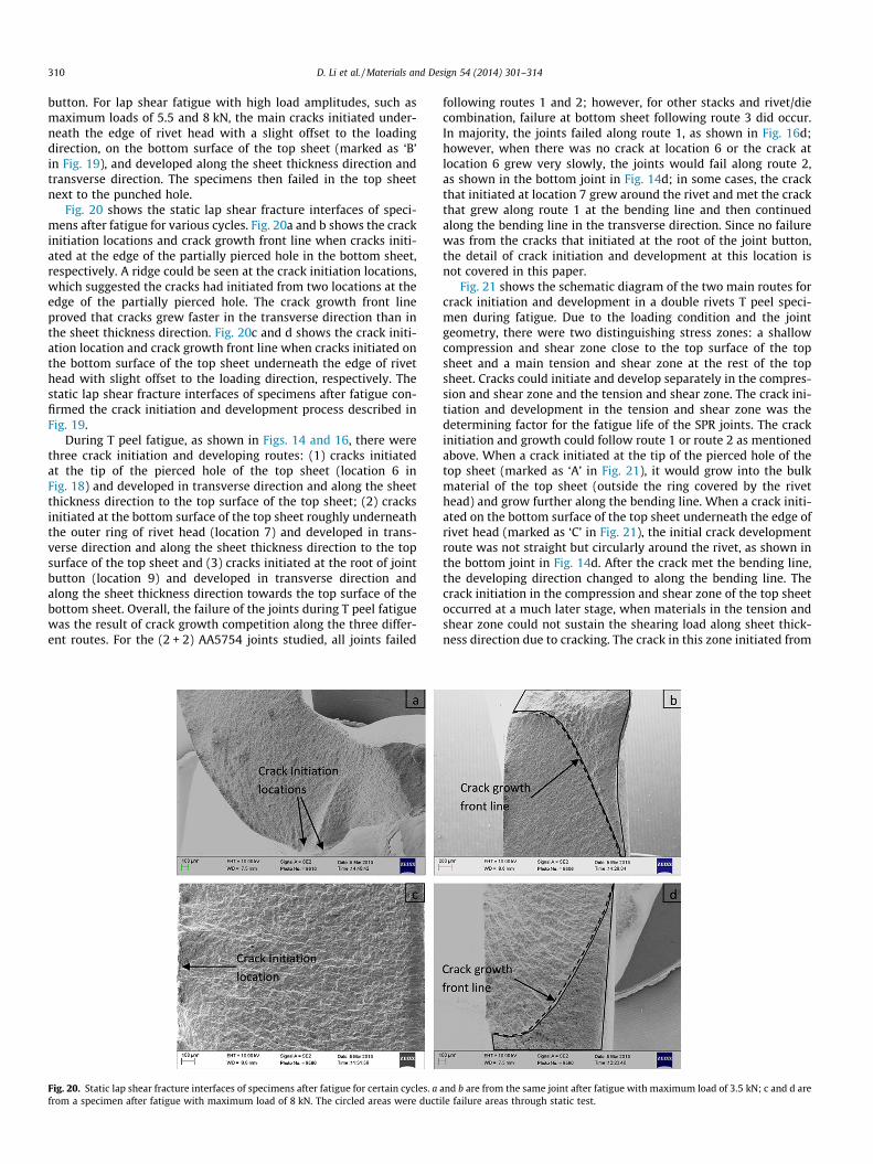
Fig. 20 shows the static lap shear fracture interfaces of speci-mens after fatigue for various cycles. Fig. 20a and b shows the crackinitiation locations and crack growth front line when cracks initi-ated at the edge of the partially pierced hole in the bottom sheet,respectively. A ridge could be seen at the crack initiation locations,which suggested the cracks had initiated from two locations at theedge of the partially pierced hole. The crack growth front lineproved that cracks grew faster in the transverse direction than inthe sheet thickness direction. Fig. 20c and d shows the crack initi-ation location and crack growth front line when cracks initiated onthe bottom surface of the top sheet underneath the edge of rivethead with slight offset to the loading direction, respectively. Thestatic lap shear fracture interfaces of specimens after fatigue con-firmed the crack initiation and development process described inFig. 19.
During T peel fatigue, as shown in Figs. 14 and 16, there werethree crack initiation and developing routes: (1) cracks initiatedat the tip of the pierced hole of the top sheet (location 6 inFig. 18) and developed in transverse direction and along the sheetthickness direction to the top surface of the top sheet; (2) cracksinitiated at the bottom surface of the top sheet roughly underneaththe outer ring of rivet head (location 7) and developed in trans-verse direction and along the sheet thickness direction to the topsurface of the top sheet and (3) cracks initiated at the root of jointbutton (location 9) and developed in transverse direction andalong the sheet thickness direction towards the top surface of thebottom sheet. Overall, the failure of the joints during T peel fatiguewas the result of crack growth competition along the three differ-ent routes. For the (2 + 2) AA5754 joints studied, all joints failed
Fig. 20. Static lap shear fracture interfaces of specimens after fatigue for certain cycles. afrom a specimen after fatigue with maximum load of 8 kN. The circled areas were duct
following routes 1 and 2; however, for other stacks and rivet/diecombination, failure at bottom sheet following route 3 did occur.In majority, the joints failed along route 1, as shown in Fig. 16d;however, when there was no crack at location 6 or the crack atlocation 6 grew very slowly, the joints would fail along route 2,as shown in the bottom joint in Fig. 14d; in some cases, the crackthat initiated at location 7 grew around the rivet and met the crackthat grew along route 1 at the bending line and then continuedalong the bending line in the transverse direction. Since no failurewas from the cracks that initiated at the root of the joint button,the detail of crack initiation and development at this location isnot covered in this paper.
Fig. 21 shows the schematic diagram of the two main routes forcrack initiation and development in a double rivets T peel speci-men during fatigue. Due to the loading condition and the jointgeometry, there were two distinguishing stress zones: a shallowcompression and shear zone close to the top surface of the topsheet and a main tension and shear zone at the rest of the topsheet. Cracks could initiate and develop separately in the compres-sion and shear zone and the tension and shear zone. The crack ini-tiation and development in the tension and shear zone was thedetermining factor for the fatigue life of the SPR joints. The crackinitiation and growth could follow route 1 or route 2 as mentionedabove. When a crack initiated at the tip of the pierced hole of thetop sheet (marked as ‘A’ in Fig. 21), it would grow into the bulkmaterial of the top sheet (outside the ring covered by the rivethead) and grow further along the bending line. When a crack initi-ated on the bottom surface of the top sheet underneath the edge ofrivet head (marked as ‘C’ in Fig. 21), the initial crack developmentroute was not straight but circularly around the rivet, as shown inthe bottom joint in Fig. 14d. After the crack met the bending line,the developing direction changed to along the bending line. Thecrack initiation in the compression and shear zone of the top sheetoccurred at a much later stage, when materials in the tension andshear zone could not sustain the shearing load along sheet thick-ness direction due to cracking. The crack in this zone initiated from
and b are from the same joint after fatigue with maximum load of 3.5 kN; c and d areile failure areas through static test.
Fig. 21. Schematic diagram for crack initiation and development for a double rivets T peel specimen during fatigue. (A) Crack initiation location in the tension and shear zoneat the tip of the punched hole in the top sheet; (B) crack initiation location in the compression and shear zone at the edge of the punched hole in the top sheet; (C) crackinitiation location in the tension and shear zone underneath the edge of rivet head with a slight offset to the bent on the bottom surface of the top sheet. The crack growthlines for the compression and tension zones are not from the same stage: crack initiation at the compression and shear zone is later than that at the tension and shear zone.
D. Li et al. / Materials and Design 54 (2014) 301–314 311
the top surface at the edge of the punched hole (marked as ‘B’ inFig. 21) and then grew along sheet thickness direction to theboundary of the compression/tension zones and along transversedirection. For these two main crack initiation and developmentroutes, the material close to the compression/tension boundaryin the compression zone was always the last material to fail, atany fixed distance to the punched hole along transverse direction.
Fig. 22 shows the static T peel fracture interfaces of specimensafter fatigue for certain cycles. Fig. 22a–c is fracture interfaces fromthe same specimen after fatigue with maximum load of 0.7 kN atdifferent locations: Fig. 22a shows the punched hole with crack ini-tiation location at the tip of the punched hole; Fig. 22b and c showsthe fracture interfaces away from the punched hole, with Fig. 22bbeing closer to the hole. It can be seen that a strip of material closeto the compression/tension boundary in the compression zone re-mained during fatigue but was pulled apart during the followingstatic test. Fig. 22d shows the fracture interface of a specimen withthe crack initiation location at the tip of the punched hole in thetop sheet, after fatigue with a maximum load of 1.8 kN. The crack
Fig. 22. Static T peel fracture interfaces of specimens after fatigue for certain cycles. a–specimen after fatigue with maximum load of 1.8 kN. The circled areas were ductile fai
growth front line indicated that cracks grew faster along the trans-verse direction than along sheet thickness direction. The static Tpeel fracture interfaces of specimens after fatigue confirmed thecrack initiation and development process described in Fig. 21.
4.3. Influence of fretting on fatigue
For lap shear fatigue, the main fretting areas were between thetip of the punched hole in the top sheet and the edge of the par-tially pierced hole in the bottom sheet, as analysed in Fig. 17. Dur-ing a fatigue process, friction will make the contact interfacesrougher than that in the initial joint state. From the fracture inter-faces, it can be seen that the fretting area stayed similar during thefatigue process, but at higher applied loads fretting wear was widerin the transverse direction than at lower applied loads.
There are two tensile stress concentration locations during lapshear fatigue due to secondary bending as shown in Fig. 17: loca-tion 3 and location 4. From the fracture interfaces and joint crosssections, cracks at both of these two stress concentration locations
c are from the same joint after fatigue with maximum load of 0.7 kN; d is from alure areas through static test.
312 D. Li et al. / Materials and Design 54 (2014) 301–314
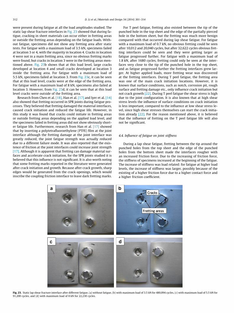
were present during fatigue at all the load amplitudes studied. Thestatic lap shear fracture interfaces in Fig. 23 showed that during fa-tigue, cracking in sheet materials can occur either in fretting areasor outside the fretting areas depending on the fatigue loads. With-out fatigue, specimens did not show any fretting area after statictests. For fatigue with a maximum load of 3.5 kN, specimens failedat location 3 or 4, with the majority in location 4. Cracks in location4 were not in a main fretting area, since no obvious fretting markswere found, but cracks in location 3 were in the fretting areas men-tioned above. Fig. 23b shows that at this load level, large cracksdeveloped at location 4 and small cracks developed at location 3inside the fretting area. For fatigue with a maximum load of5.5 kN, specimens failed at location 3. From Fig. 23c, it can be seenthat at this load level, cracks were at the edge of the fretting area.For fatigue with a maximum load of 8 kN, specimens also failed atlocation 3. However, from Fig. 23d, it can be seen that at this loadlevel cracks were outside of the fretting area.
Research from Chen et al. [18], Han et al. [17] and Iyer et al. [14]also showed that fretting occurred in SPR joints during fatigue pro-cesses. They believed that fretting damaged the material interfaces,caused crack initiation and reduced the fatigue life. However, inthis study it was found that cracks could initiate in fretting areasor outside fretting areas depending on the applied load level, andthe specimens failed in fretting areas did not show obviously short-er fatigue life. Furthermore, research from Han et al. [17] showedthat by inserting a polytetrafluoroethylene (PTFE) film at the jointinterface although the fretting damage at the joint interface wasgreatly reduced, the joint fatigue strength was actually reduceddue to a different failure mode. It was also reported that the exis-tence of friction at the joint interfaces could increase joint strength[17]. Although it is apparent that fretting can damage material sur-faces and accelerate crack initiation, for the SPR joints studied it isbelieved that this influence is not significant. It is also worth notingthat some fretting marks reported in the literature were generatedafter crack initiation and growth. Because after crack growth, sharpedges would be generated from the crack openings, which wouldinscribe the coupling friction interface to leave dark fretting marks.
Fig. 23. Static lap shear fracture interface after different fatigue, (a) without fatigue, (b) w91,200 cycles, and (d) with maximum load of 8 kN for 22,230 cycles.
For T peel fatigue, fretting also existed between the tip of thepunched hole in the top sheet and the edge of the partially piercedhole in the bottom sheet, but the fretting was much more benigncompared with that occurred during lap shear fatigue. For fatiguewith a maximum load of 0.7 kN, no obvious fretting could be seenafter 10,012 and 20,040 cycles, but after 32,622 cycles obvious fret-ting interfaces could be seen and they were getting larger asfatigue progressed further. For fatigue with a maximum load of1.8 kN, after 1680 cycles, fretting could only be seen at the inter-faces very close to the tip of the punched hole in the top sheet,and as fatigue progressed further the fretting interfaces grew lar-ger. At higher applied loads, more fretting wear was discoveredat the fretting interfaces. During T peel fatigue, the fretting areawas one of the main crack initiation locations. However, it isknown that surface conditions, such as notch, corrosion pit, roughsurface and fretting damage etc., only influence crack initiation butnot crack growth [22]. During T peel fatigue the shear stress is highdue to the joint configuration. It is also known that at high shearstress levels the influence of surface conditions on crack initiationis less important, compared to the influence at low shear stress le-vel, since high shear stresses themselves can start the crack initia-tion already [22]. For the reason mentioned above, it is believedthat the influence of fretting on the T peel fatigue life will alsonot be significant.
4.4. Influence of fatigue on joint stiffness
During a lap shear fatigue, fretting between the tip around thepunched holes from the top sheet and the edge of the punchedholes from the bottom sheet made the interfaces rougher withan increased friction force. Due to the increasing of friction force,the stiffness of specimens increased at the beginning of the fatigue.The increase of stiffness was load related: for fatigue at higher loadlevels, the increase of stiffness was larger, possibly because of theexisting of a higher friction force due to a higher contact force anda higher friction coefficient.
ith maximum load of 3.5 kN for 480,094 cycles, (c) with maximum load of 5.5 kN for
D. Li et al. / Materials and Design 54 (2014) 301–314 313
During the following fatigue process, the stiffness remained al-most constant, because the crack initiation was very slow in lapshear fatigue and the friction force could not be increased further.This period was also load related: for fatigue with lower load lev-els, the crack initiation would take much longer than that for fati-gue with higher load levels. Although research from Briskham [23]showed that the stiffness of SPR specimens did not have obviousdrop after long cracks appeared, our results showed that whencracks started to grow, the stiffness of specimens would start todrop until the specimens failed.
Compared with the secondary bending in lap shear tests, thebending in T peel fatigue tests was much larger. When a smaller fa-tigue load was applied, such as fatigue with a maximum load of0.7 kN, the bending was still in the elastic deformation region,and as a result after fatigue the shape of the specimens did nothave obvious change. But when a larger fatigue load was applied,such as fatigue with a maximum load of 1.8 kN, the bending ex-tended to the plastic deformation region, and as a result after fati-gue the specimens were severely bent. Due to this severe bending,the geometry of specimens changed, resulting in the increase of thespecimen stiffness at the beginning of fatigue. However, for thespecimens under fatigue with maximum load of 0.7 kN, becausethere was no obvious geometry change during fatigue, the stiffnessof the specimens did not have obvious change at the beginning offatigue.
For T peel fatigue at low load levels, such as with a maximumload of 0.7 kN, the stiffness of specimens started to gradually drop,due to the initiation and development of cracks in the specimensduring T peel fatigue tests. For T peel fatigue at high load levels,such as with a maximum load of 1.8 kN, the stiffness of specimensincreased immediately because of the joint geometry changecaused by the severe bending; then due to the initiation and devel-opment of cracks in the specimens, the stiffness of specimensstarted to gradually drop. At the late stage of fatigue when thespecimens were close to failure, the peel force was trying to pullthe top sheet material between the rivet head and the bottomsheet out of the gap between them with rotation around the pivot(edge of the rivet head). Due to the reason mentioned in Section 3.4,the joint became tighter and its stiffness started to increase. At thisstage, this tightening effect was competing with the influence ofcracking on stiffness. The tightening effect reached the maximumwhen the punched tip in the top sheet was squeezed to the nar-rowest gap through rotation, and then the influence from tighten-ing would reduce. With cracks developing further, the stiffness ofspecimens would start to drop again, and a sudden failure wouldoccur as the joints were overloaded.
4.5. Influence of fatigue on remaining static strength
During static lap shear tests, part of the applied force was sus-tained by the friction force between the tip around the punchedholes from the top sheet and the edge of the partially pierced holesfrom the bottom sheet. As a result, the overall force required tobreak a SPR lap shear joint is the sum of the friction force andthe force required to pull out the rivet from the top and/or the bot-tom sheets in a lap shear configuration. Due to the increasing of thefriction force during lap shear fatigue, the remaining static lapshear strength of the specimens increased. In the meantime, crackswere initiating and developing during fatigue, which would reducethe joint strength. So there was a competition between the weak-ening from cracking and strengthening from fretting, and whencracks had developed to a scale large enough, the static lap shearstrength of the specimens would start to drop. In this study, theremaining static lap shear strength was higher than that of asjoined specimens, even shortly before the specimens failed from
fatigue, which indicated the influence from fretting on remainingstatic lap shear strength was significant.
Compared with the friction in lap shear fatigue specimens, thefriction existing in T peel fatigue specimens were much smaller be-cause the pulling direction was almost parallel with the punchedhole and the contact force was much lower. As a result, the fric-tions in T peel specimens did not contribute much to the static Tpeel strength and subsequently had no obvious influence on thestatic T peel strength. Due to the initiation and development ofcracks in the specimens, the remaining static T peel strength ofspecimens started to gradually drop shortly after the beginningof T peel fatigue.
Discussion in Sections 4.4 and 4.5 shows that, for lap shearjoints, fatigue can increase the remaining static strength and alsothe joint stiffness at the beginning of fatigue, but on the other sidefor T peel joints, fatigue can reduce the remaining static strengthand also severely bend the joint at high load levels although withincreased stiffness. Results showed that apart from the slightlydropping of the stiffness of T peel joints at low load levels, the stiff-ness of the SPR joints studied was higher than their original stiff-ness during majority of their fatigue life. So if the main loadbearing structures of a vehicle are in a lap shear configuration withSPR joints, then due to the increased stiffness and remaining staticstrength the vehicle may have better driving performance and rid-ing comfort during majority of its using life than in its as-manufac-tured state.
5. Conclusions
Two key areas with respect to the fatigue of self-pierced rivetedaluminium lap shear and T peel joints have been studied: the crackinitiation and development mechanisms, and the influence of fati-gue on the stiffness and remaining static strengths of the joints.The following conclusions can be drawn:
(1) For lap shear fatigue, cracks could initiate on the bottom sur-face of the top sheet underneath the edge of rivet head withslight offset to the load direction or at the two intersectionsof bending line and the top edge of the partially pierced holein the bottom sheet depending on the applied load levels.
(2) For T peel fatigue, cracks could initiate and develop throughdifferent locations on the top or bottom sheet materials. Themain failure of the specimens studied was from crack initia-tion on the bottom surface of the top sheet underneath theedge of rivet head with a slight offset to the bent or at thetip of the punched hole in the top sheet.
(3) Overall the influence of fretting on fatigue strengths is con-sidered to be not significant.
(4) Fatigue increased the remaining static lap shear strength ofspecimens due to the increased friction force between thetip of the punched hole in the top sheet and the edge ofthe partially pierced hole in the bottom sheet through fret-ting; fretting also increased the stiffness of specimens atthe beginning of lap shear fatigue.
(5) On the other side, fatigue reduced the remaining static T peelstrength of specimens due to crack initiation and develop-ment; T peel fatigue at high load levels also increased thestiffness of specimens at the beginning of fatigue due togeometry change through large plastic deformations.
(6) For both lap shear and T peel, the stiffness of specimensstarted to drop once cracks started to grow during fatigue.However, apart from the slightly dropping of the stiffnessof T peel joints at low load levels, the stiffness of the SPRjoints studied was higher than their original stiffness duringmajority of their fatigue life.
314 D. Li et al. / Materials and Design 54 (2014) 301–314
Acknowledgements
The authors would like to thanks TSB, the European RegionalDevelopment Fund and the Advanced West Midlands Fund, UK,for the support of this research. The authors would also like tothanks Henrob Ltd. for providing the rivets for this research.
References
[1] Krause AR, Chernenkoff ARA. A comparative study of the fatigue behaviour ofspot welded and mechanically fastened aluminium joints. SAE world congress1995. Paper no. 950710.
[2] Booth GS, Olivier CA, Westgate SA, Liebrecht F, Braunling S. Self-piercingriveted joints and resistance spot welded joints in steel and aluminium. SAEworld congress 2000. Paper no. 2000-01-2681.
[3] Sun X, Stephens EV, Khaleel MA. Fatigue behaviors of self-piercing rivetsjoining similar and dissimilar sheet metals. Int J Fatigue 2007;29(2):370–86.
[4] Abe Y, Kato T, Mori K. Joinability of aluminium alloy and mild steel sheets byself piercing rivet. J Mater Process Technol 2006;177(1–3):417–21.
[5] Li D, Han L, Thornton M, Shergold M. An evaluation of quality and performanceof self-piercing riveted high strength aluminium alloy AA6008 for automotiveapplications, SAE world congress 2010. Paper No. 2010-01-0223.
[6] Hoang NH, Hopperstad OS, Langseth M, Westermann I. Failure of aluminiumself-piercing rivets: An experimental and numerical study. Mater Des2013;49:323–35.
[7] Hoang NH, Porcaro R, Langseth M, Hanssen AG. Self-piercing rivetingconnections using aluminium rivets. Int J Solids Struct 2010;47(3–4):427–39.
[8] Esfahani M, Durandet Y, Wang J, Wong Y. Effect of joining process on thecoatings of self-piercing rivets. Adv Mater Res 2012;488–489:1501–5.
[9] Han L, Chrysanthou A, Young KW. Mechanical behaviour of self-piercingriveted multi-layer joints under different specimen configurations. Mater Des2007;28(7):2024–33.
[10] Porcaro R, Hanssen AG, Langseth M, Aalberg A. The behaviour of a self-piercingriveted connection under quasi-static loading conditions. Int J Solids Struct2006;43(17):5110–31.
[11] Li D, Han L, Shergold M, Thornton M, Williams G. Influence of Rivet TipGeometry on the Joint Quality and Mechanical Strengths of Self-PiercingRiveted Aluminium Joints. Mater Sci Forum 2013;765:746–50.
[12] Li D, Han L, Thornton M, Shergold M. Influence of edge distance on quality andstatic behaviour of self-piercing riveted aluminium joints. Mater Des2012;34:22–31.
[13] Li D, Han L, Thornton M, Shergold M. Influence of rivet to sheet edge distanceon fatigue strength of self-piercing riveted aluminium joints. Mater Sci Eng A2012;558:242–52.
[14] Iyer K, Hu SJ, Brittman FL, Wang PC, Hayden DB, Marin SP. Fatigue of single-and double-rivet self-piercing riveted lap joints. Fatigue Fract Eng Mater Struct2005;28(11):997–1007.
[15] Fu M, Mallick PK. Fatigue of self-piercing riveted joints in aluminum alloy6111. Int J Fatigue 2003;25(3):183–9.
[16] Li B, Fatemi A. An experimental investigation of deformation and fatiguebehavior of coach peel riveted joints. Int J Fatigue 2006;28(1):9–18.
[17] Han L, Chrysanthou A, O’Sullivan JM. Fretting behaviour of self-piercingriveted aluminium alloy joints under different interfacial conditions. MaterDes 2006;27(3):200–8.
[18] Chen YK, Han L, Chrysanthou A, O’Sullivan JM. Fretting wear in self-piercingriveted aluminium alloy sheet. Wear 2003;255(7–12):1463–70.
[19] Sampò E. Modelling chassis flexibility in vehicle dynamics simulation, PhDthesis, in Faculty of Engineering and Physical Sciences, University of Surrey,2011.
[20] Helsen J, et al. Global static and dynamic car body stiffness based on a singleexperimental modal analysis test. In: Proceeding of ISMA 2010-USD 2010.Leuven, Belgium; 2010.
[21] Fleck NE, Shin CS, Smith RA. Fatigue crack growth under compressive loading.Eng Fract Mech 1985;21(1):173–85.
[22] Schijve J. Fatigue of structures and materials. 2nd ed. Springer; 2009.[23] Briskham P. Durability testing of riveted, bonded and hybrid aluminium joints
for automotive body structures. In: LATEST2 joining conference, 2011.