The influence of screw feeders on bin flow patterns
Y. Yu, P.C. Arnold Department of Mechanical Engineeriug. University of Wollongong. Wollongong, NSW, Australia
Received 20 October 1995
Abstract
Screw feeders are often used in bulk solid handling systems to control the feed from mass-flow bins with wedge or transition shaped hoppers. This requires good geometric design of the outlet-feeder combination in order for the bulk solids to be entrained over the full length of the outlet. Otherwise, unnecessary problems are likely to occur. Achieving an even flow pattern in the bin or hopper can minimize these problems. There are several methods to increase screw capacity in the direction of feed, e.g. stepped pitch, tapered shaft, tapered screw diameter; or a combination of these methods. In this paper a theoretical model for achieving a uniform flow pattern is proposed based on the pitch characteristic of screws. The limitations of some methods for increasing the screw cape~ity are discussed. Experimental studies on the flow pattern in a wedge hopper with a screw feeder are also included. Four screws of different configurations were investigated on a test fig. All the screws had increased screw capacity in the flow direction. In the experiments a dividing grid was fitted above the screw to form a central division over the axis of the screw to isolate each side into a number of divisions which matched the different pitches of the screw. The results from the experiments are presented and compared with the theoretical predictions.
Keywords: Screw feeders; Pitch characteristics: Bin flow patterns
1. In t roduc t ion
Many industrial processes require controlled feeding. Screw feeders are one of the most useful feeding devices whic t not only have good metering characteristics, but also use relatively simple eomponents and can be designed to feed reliably many kinds of bulk solids in a variety of applications. Screw feeders can be used for different hopper shapes and are commonly fitted to plane-mass-flow bins or hoppers with slotted outlets. This requires that specia~ precautions be taken in the design of the hopper outlet-feeder combination in order for the bulk solids to be withdrawn as evenly as possible over the full length of the outlet. If this is not the case the draw- down in the bin will be far from uniform and, in a worse case, material will only be withdrawn at the rear end of the bin. To minimize this problem methods are employed to increase the volume of the screw in the direction of flow. Common tech- niques arc to increase the pitch of the screw, decrease the shaft diameter, increase the screw diameter, or a combination of these.
Bates [ 1 ] studied the flow pattern developed by a screw feeder in a hopper. A series of tests on each combination of screw and material was undertaken to compare the different flow patterns. In later papers Bates reviews the requirements
for interfacing hoppers with screw feeders [ 2,3 ]. Carson [4] reviews desigq procedures that can help to improve screw feeder performance. He also discusses the interaction mech- anisms between proper bin design and optimum screw feeder design. More recently a theory has been proposed by Roberts [5] to evaluate the characteristics o f a given screw feeder. The core of his theory is the proposed criterion for uniform draw-down, which is used in later papers [6,7] to extend the concepts to predict the flow patterns generated in the hopper by a giver screw. Haaker et al. [ 8] discuss a theoretical base for the volumetric efficiency of screw feeders ar~ propose a method for optimal pitch design to increase tile screw capacity in the flow direction. In the present paper a theoretic~ model for a uniform flow pattern is proposed based on the pitch characteristic o f screws. The limitations of scme methods for increasing the screw capacity are discussed. Experimental studies on the flow pattern in a wedge hopper with a screw feeder are also included. Four screws o f different configura- tions were investigated on a test rig. All the screws had increased screw capacity in the flow direction. In the exper- iments a dividing grid was fitted above the screw to form a central division over the axis o f the screw to isolate each side into a number of divisions which matched the different pitches of '-he screw. The resalts from the experiments are presented and compared with the theoretical predictions.
Y. Yu, P. C. Arnold~Powder Technology 88 (1996) 81-87
2. Theory for a uniform flow pat tern
A screw feeder fitted to a plane-mass-flow bin is shown in Fig. 1. We assume the diameter of the screw flight, the diam- eter of the core or shaft, and the pitch to be functions of the conveying direction of lhe screw feeder. At any location x the relevant geometric variables of the screw are pitch P(x), outside diameter D(x) of the screw, and core or shaft diam- eter d(x).
The cross-sectional area is given by
A(x) =4[ D(x)2-d(x)2]
In one revolution, the screw advances one pitch, P(x). If the thickness of the screw flight is negligible, the maximum theoretical volume withdrawn per revolution is
Vt(x) =A(x)P(x)
This implies complete filling of the screw and no rotation of the material. In reality, however, the material rotates and follows a helical path at an angle with the plane perpendicular to the axis, as shown in Fig. 2.
Thus, the actual withdrawn volume is
V(x) =A(x)r/~(x)P(x) ( ! )
where r/v is the volumetric efficiency. The volumetric effi- ciency is composed of two comp,, =ents: the rotational effect and the fullness effect. For screw feeders operating at low speed, the fullness effect is very small and the screw can be considered to be operating 100% 'full'. The dominant factor influencing the volumetric efficiency is the rotational motion which is a function of the screw geometry as well as the coefficient of friction of the material on the flight face. The following equation for the volumetric efficiency is proposed:
tan/3c
tan c~ c + tan/3c
The equations for calculation of a¢ and/3¢ are [9]
Fig. I. A screw feeder with a plane-mass-flow bin.
i I,,i sa.cw exl.
I Fig. 2. Direction of material element motion.
In general, the pitch of a screw can be regarded as varying incrementally rather than continuously. Hence, along the feeding length the pitch can be expressed as
Pt =Xl P2=x2-xl
Pt. = pitch at feeder outlet
Within a particular pitch, Eq. ( 1 ) can be written as
V~(x) =PiA(x)~lv(x) i= 1 . . . . . L (2)
From Eq. (2), it can be seen that if a screw feeder has variable pitches, the transported volume is not a continuous function along the feed length but is also incremental. In considering the flow pattern in a hopper fitted with a screw feeder the withdrawn volume can be considered separately in each pitch. Within a pitch the average effective area is defined as
x,
Aai= I A,(x)a%(x) dx x,-i
The volume transported per revolution in pitch i is
V, = P, Aa, (3)
For many processes, the material should be withdrawn uniformly from the entire hopper outlet area; this requires a screw capacity which increases with length. To satisfy this requirement the volumetric transportation should be consis- tent with the following equations:
V2= VI + P2Aal =Aal (PI +P2)
A =A PI+---P2 a2 al P2
In general,
V i = V~_ l + P~Aal = Aal (Pi + P2 +"" + Pi)
tPt + P2 + " " + P~ A a/---- ga ~ Pi
(4)
and at the feeder outlet
E Yu, P.C. Arnold~Powder Technology 88 (1996) 81-87
L A ~ = A,, p'-~L (5)
Eq. (4) is the required criterion for uniform draw-down performance and Eq. (5) is the boundary conditiot~. From Eqs. (4) and (5) it can be concluded that the average effec- tive area in the first pitch has a very important influence on the performance of the whole screw. In actual applications it is difficult to provide the increasing capacity of every pitch to satisfy the criterion. A profile coefficient is introduced to allow the withdrawal performance of a particular screw to be compared with the ideal:
A.~-A.~_ , ( Pi- , / P~) fpi Aa ' (6)
fp = I for ideal uniform withdrawal performance and fp = 0 for no increment in a pitch.
3. Limitations of some design methods
Typically, screw feeders are designed with a constant-pitch screw in which the pitch is usually equal to the screw diam- eter. Unfortunately, a constant-pitch screw is not suited to a rectangular hopper outlet; it only withdraws material from approximately one pitch length near the back end of the bin outlet. There are three main methods to increase screw capac- ity with length, namely, stepped pitch, tapered shaft or tapered screw diameter (Fig. 3). The nomenclature in the following analysis is related to this figure.
3./. Stepped pitch
As shown in Fig. 3(a) , along the whole feed length thc cross-sectional area is constant and within a pitch the volu- metric efficiency is also constant, i.e.
Patio P'JPi-I Fig. 4. Profile coefficientfp for a stepped-pitch, uniform-diameter screw.
A(x) =A
~lv~( x ) = 71v~
According to Eq. (2) the volume transported per revolu- tion in pitch i is
V , = t ' , a m ,
Comparing this with the required criterion for uniform draw-down performance (Eqs. (4) and (5 ) ) , it can be seen that a screw with stepped pitch and uniform diameter cannot, theoretically speaking, provide a uniform withdrawal flow pattern, because 'there is no increment in the average effective area. In practice, the variable pitch range of a screw is limited. Based on experimental investigations and experience, the minimum pitch should not be less than one third oftbe screw diameter and the maximum pitch should be approximately one screw diameter for most materials. If the pitch is too small the pocket between the shaft and the first two flights is so narrow that the material compacts and rotates with the screw. This results in no material being fed into the adjacent section of the screw. Above the upper bound of the pitch, the flight forces the material to rotate excessively with the screw rather than move toward the discharge end and the volumetric efficiency is greatly decreased.
As a simple case, one can assume a constant volumetric efficiency. The profile coefficient in pitch i can be approxi- mated by
P~_, fpi = 1 P,
The range of the profile coefficient is shown in Fig. 4.
3.2. Tapered shaft, uniform pitch
The pitch is constant along th, vhole feed length as shown in Fig. 3(b) , i.e.
P! =P2 . . . . . PL = P
The volume withdrawn in pitch i is
V~ = PAai
Similar to the case in Section 3.1, a constant volumetric efficiency is assumed. As an example, the profile coefficient
Y. Y., P. C. Arnold~Powder Technology 88 (1996) 81--87
Fig. 5. Variation of f~,, with L/D and dn/D for a tapered-shaft screw (d/D = I/3 and P/D = 1 ).
1"0t ~ DI/D=-O.5 [
°., 1 • D~-o.~ I o.o _ i ,~ 0 . 2
0.0 3 4 5 6
Ratio L/D Fig. 6 Variation offp~ with L/D and Dn/D for a tapered-diameter screw (P/D o= 0.7 and d/D = I/3).
in the second pitch is considered in order to understand the effect of the feeding length L and the shaft diameter dt at the beginning of the first pitch on the profile coefficient. Their relationships are shown in Fig. 5. It can be seen that the profile coefficient is very sensitive to the ratio d ~ / D which deter- mines the volume withdrawn in the first pitch. When d n / D is less than 0.8 the profile coefficient is less ~han 0.5.
3.3. Tapered s c r e w diameter , uni form pi tch
The proposed assumptions are the same as in Section 3.2; again the profile coefficient in the second pitch is considered. The rel',~ionships between the geometric variables are shown in Fig. 6.
Because the narrow back et~d is prone to having arches form over it and it is difficult to fabricate properly the screw trough and the interface with the bin, the tapered-diameter screw is not recommended for most materials.
In the above discussion the volumetric efficiency of the screw feeder is neglected. However, the volumetric efficiency decreases with increase in the ratio of the pitch to the screw diameter. It also decreases with decrease in the ratio of the shaft diameter to the screw diameter. These negative effects on the profile coefficient are further exacerbated by the inclu- sion of volumetric efficiency.
4 . E x p e r i m e n t a l
The test rig shown in Fig. 7 consists of screws of four different configurations and a variable-geometry plane-flow
hopper with vertical end walls which allows both the hopper geometry and the slot opening width to be changed. The four test screws (Fig. 8) are listed as follows:
No. 1, stepped pitch and uniform diameter, No. 2, tapered shaft and stepped pitch, No. 3, variable-width ribbon flight and stepped pitch, No. 4, stepped shaft and stepped pitch. A dividing grid was fitted over the screw to form a central
division above the axis of the screw and isolate each zide into a number of divisions which matched the different pitches of each screw. The screw was driven by an electric motor via a shaft-mounted gear box which connected a transducer for recording the screw torque. The rotating speed of the screw was varied by frequency control of the drive motor. The screw speed or the amount of rotation was measured by a counter.
m ~ M ~ a
hopper
I I , , , , _
Fig. 7. Test rig for screw feeders.
5o.3 7s.3 loo.~ m.~ (a)
_~o 6s .3s .~ . j~ ,~ ton ~zs.6 ~b ~
50 .ca _/sol__ _.~s,Z.__l~.~ izs-6 ~. (C)
" i " f f ' ~ V ~ ; ~ V v , i v , ,
( d )
Fig. 8. Configurations of the test screws: (a) No. I, step~d pitch and uniform diameter; (b) No. 2. tapered shaft mid stepped pitch; (c) No. 3, ribbon flight and stepped pitch; (d) No. 4, stepped shaft and pitch.
Y. Yu, P.C. Arnold~Powder Technology 88 (1996) 81-87
White plastic pellets were used in the experiments. The measured flow properties were: Bulk density Pb 530 kg/m 3 Particle density Ps 893 kg/m 3 Mean equivalent diameter dm 3.7 mm Effective angle of internal friction 8 44 ° Wall friction angle on mild steel 0w 17 °
The effective angle of internal friction and the wall friction angle on mi! a - steel were determined by measurements with a Jenike-type shear tester.
The material was loosely poured into the hopper. After several revolutions of the screw the hopper was refilled and trimmed level to secure equilibrium conditions in the bulk material. Measurements of the fall of the level were then taken at each division after each two successive rotations of the screw. Preliminary trials confirmed that the flow pattern and total quantity withdrawn did not show a significant variation over a speed range from 10 to 80 rpm. Tests rep,.~ted here were carried out at 20 rpm.
5. Results
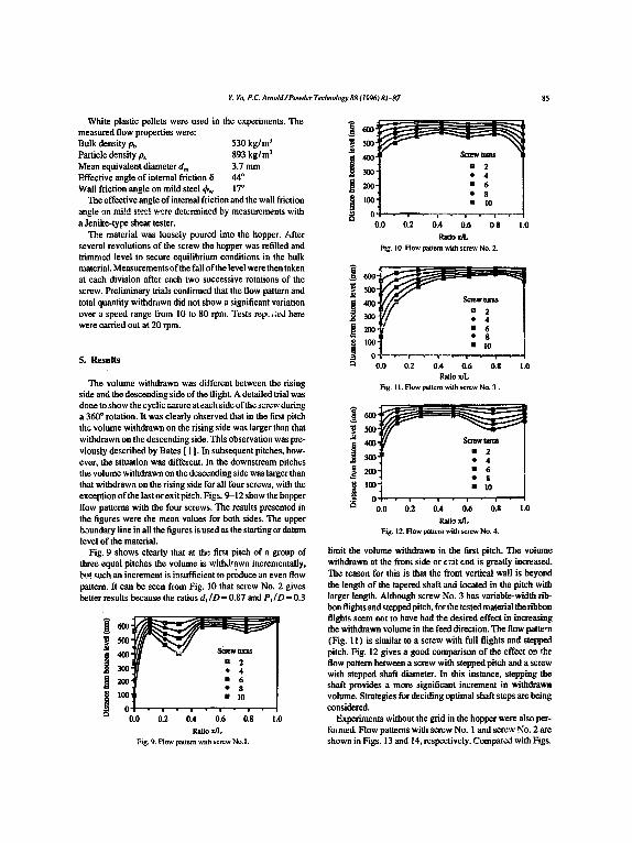
The volume withdrawn was different between the rising side and the descending side of the flight. A detailed trial was done to show the cyclic nature at each side of the screw during a 360 ° rotation. It was clearly observed that in the first pitch the volume withdrawn on the rising side was larger than that withdrawn on the descending side. This observation was pre- viously described by Bates [ 1 ]. In subsequent pitches, how- ever, the situation was different. In the downstream pitches the volume withdrawn on the descending side was larger than that withdrawn on the rising side for all four screws, with the exception of the last or exit pitch. Figs. 9-12 show the hopper flow patterns with the four screws. The results presented in the figures were the mean values for both sides. The upper boundary line in all the figures is used as the starting or datum level of the material.
Fig. 9 shows clearly that at the first pitch of a group of three equal pitches the volume is withdrawn incrementally, b~:t. ~nch an increment is insufficient to pr~luce an even flow pattern. It can be seen from Fig. 10 that screw No. 2 gives better results because the ratios d I /D ~ 0.87 and P ~ / D = 0.3
B 2 J : - 7 - ,~ :,oo.'1 " 6
* 8 I, t :l'0 O I • , - , • , - , •
0 .0 0.2 0.4 0.6 0.8 1.0 Ratio x/L
Fig. 9. Flow pattern with screw No.l.
600 - F - - - -
I'%] . . . . . I c i
0.0 0.2 0.4 0.6 0 8 !.0 Ratio xR.
Fig. 10. Flow pattern with screw No. 2.
J g, --i- I O.0 0.2 0.4 0.6 0.8 1.0
Ratio xlL Fig. l i. Flow pattern with screw No. 3.
~ o - I • 6
0.0 0.2 0.4 0.6 0.8 1.0
Ratio xlL Fig. 12. Flow pattt;~n with screw No. 4.
limit the volume withdrawn in the first pitch. The voiume withdrawn at the front side or e:~it end :s greatly increased. The reason for this is that the front vertical wall is beyond the length of the tapered shaft and located in the pitch with larger length. Although screw No. 3 has variable-width rib- bon flights and stepped pitch, for the tested material the ribbon flights seem not to have had the desired effect in increasing the withdrawn volume in the feed direction. The flow pa t t e r (Fig. 11) is similar to a screw with full flights and stepped pitch. Fig. 12 gives a good comparison of the effect on the flow pattern between a screw with stepped pitch and a screw with stepped shaft diameter. In this instance, stepping the shaft provides a more significant increment in withdrawn volume. Strategies for deciding optimal shaft steps are being considered.
Experiments without the grid in the hopper were also per- formed. Flow patterns with screw No. I and screw No. 2 are shown in Figs. 13 and 14, respectively. Compared with Figs.
E Yu. P.C Arnold~Powder Technology 88 (1996) 81-87
A
. , . . . . , 0 0.0 0.2 0.4 0.6 0.8 1.0
Ratio x/L Fig. 13. Flow pattern without grid for screw No. I.
~ e00 r. .= ~ _-_- _
J ,oo] :2 ~ 200-1 • 6
,00 t 0 ! - , - , - , - , -
r~ 0.0 0.2 0.4 0.6 0.8 1.0 Ratio x/L
Fig. 14. Flow pattern without grid for screw No. 2.
9 and 10, it can be seen that the profile of the material in the hopper was modified significantly. Comparing Figs. 9 and 13, the fluctuations in the profile indicated in Fig. 9 have been eliminated, while comparing Figs. 10 and 14, an almost com- pletely uniform draw-down has been achieved. This is con- sidered an interesting result which warrants further investigation.
Fig. 15 shows the results from the experiments and theo- retical predictions of the profile coefficients of the four screws. For screw No. 3 the comparison was made for a screw having full flights and the same stepped pitches. It can be seen that the variable-width ribbon flight did not have a strong influence on decreasing the effective cross-sectional area of the screw. Because the bottom of the grid was set 30 mm over the top of the screw flights, some cross-flow may h~ve
occurred between the dividing plates. Even though this could modify the hopper flow pattern, the measurements obtained showed good consistency with those of the theoretical approach.
6. Conclusions
Based on the discussion of the limitations of several design methods and the results from experiments, some conclusions can be made.
(i) For a screw feeder with stepped pitch, there is no continuous function for expressing the volume withdrawn along the whole feed length. The pitch characteristic of a screw feeder is introduced to aid in the consideration of the resulting hopper flow pattern.
(ii) The volume withdrawn in the first pitch of a screw has a great effect on the flow pattern. With the practical limits on pitch (PI /D at the beginning and PL/D at the end) it is impossible to achieve uniform withdrawal for screws with only variable pitch
(iii) Techniques such as stepped pitch and/or tapered shaft can increase the capacity of a screw feeder to provide uniform withdrawal in the feed direction, but these methods have their limits in application, especially in a wedge hopper with a long slotted outlet.
(iv) Ribbon flights may be good for sticky or cohesive materials where the gap between the screw and the shaft prevents material build-up, but, from the experiments, this type of screw is not effective in increasing the capacity of the screw in the flow direction when used with coarse free-flow- ing materials.
(v) Because of cross-flow of material, the actual condi- tions in a bin or hopper without a grid are modified. For some very free-flowing materials such modification may be sub- stantial. This phenomenon is receiving further consideration.
7. List o f s y m b o l s
A cross-sectional area of screw (m 2 ) A~ average effective area of transportation (m 2) d core or shaft diameter (m) D screw diameter (m) fp profile coefficient L feed length (m) P pitch length (m) V volume withdrawn per revolution (m 3) Vt maximum theoretical volume withdrawn per
revolution (m 3 )
Greek letter~
a¢ equivalent helix angle of flight (deg) /3c equivalent helix angle of element motion (deg) qSr angle of frction of material on flight surface (deg)
Y. Yu. P.C. Arnold~Powder Technology 88 (1996) 81--87
r/v volumetric efficiency p f coefficient o f friction o f material on flight surface
Refe rences
[ I l L. Ba~.es, Trans. ASME, J. Eng. Ind., 91 (1969) 295-302, [2] L. Bates, Bulk Solids Handl., 6 ( I ) (1986) 65-78. 131 L. Bates, Powder Handl. Process., 6 (2) (1994) 215-221. [4l J. Carson, Powder Balk Eng., (Dec.) (1987) 32-36, 41-42.
[5] A.W. Roberts, Proc. Bulk 2000 Conf., Oct. 1991, Institution of Mechanical Engineers, London, 1991, pp. I I 1-116.
[6] A.W Roberts, K.S. Manjunath and W. McBride, Trans. Mech. Eng. (Inst. Eng. Aust.). ME-18 ( I ) (1993) 67-73.
[ 7 ] K.S Manjunath and A.W. Roberts, Proc. Pawder andBulk Solids Conf., Chicago, IL~ USA, May 1994, pp. 171-188.
[ 8] G. Hanker, M.P. Poppelen. M.P. Jongejana and J.H. Bekhuis, Proc. Int. Syrup. Reliable Flow of Particulate Solids !1. Oslo. Norway, Aug. 1993, pp. 551-561.
[9] Y. Yu. Interim Res. Rep. 1. Department of Mechanical Engineering, University of Wollongong. Australia, Feb. 1994.