142
Yearbook: 2007-2008 CONCRETE TECHNOLOGY INSTITUTE OF The 12th Edition

Yearbook: 2007-2008
CONCRETE TECHNOLOGYINSTITUTE OF
The
12th Edition

Published by:THE INSTITUTE OF
CONCRETE TECHNOLOGY4 Meadows Business Park,
Blackwater, Camberley, Surrey GU17 9AB
Tel/Fax: 01276 37831Email: [email protected]
Website: www.ictech.org
ICT YEARBOOK 2007-2008
EDITORIAL COMMITTEE
Professor Peter C. Hewlett (Chairman)GROUP TECHNICAL ADVISOR FOR
JOHN DOYLE GROUP PLCPRINCIPAL CONSULTANT -
BRITISH BOARD OF AGRÉMENT LTD
Peter C. OldhamCHRISTEYNS UK LTD
Dr. Bill PriceLAFARGE CEMENT UK
Graham TaylorINSTITUTE OF CONCRETE TECHNOLOGY
Laurence E. PerkisINITIAL CONTACTS
Rights reserved. No part of this publication maybe reproduced or transmitted in any formwithout the prior written consent of the
publisher. The comments expressed in thispublication are those of the Author and not
necessarily those of the ICT.
ISSN 1366 - 4824£50.00
Engineering CouncilProfessional Affiliate

3
Yearbook: 2007-2008
CONCRETE TECHNOLOGYINSTITUTE OF
The
CONTENTS PAGE
PRESIDENT’S PERSPECTIVE 5By Bryan MarshPresident, INSTITUTE OF CONCRETE TECHNOLOGY
THE INSTITUTE 6
COUNCIL, OFFICERS AND COMMITTEES 7
FACE TO FACE 9 - 11A personal interview with Ian Ferguson
MILESTONES IN THE HISTORY OF CONCRETE TECHNOLOGY: 13 - 17THE HISTORY OF TRAINING AT THE C&CABy Duncan Pomeroy and Graham Taylor
ANNUAL CONVENTION SYMPOSIUM: 19 - 122PAPERS PRESENTED 2006128ADVANCED CONCRETE TECHNOLOGY DIPLOMA 123 - 130SUMMARIES OF PROJECT REPORTS 2006
RELATED INSTITUTIONS & ORGANISATIONS 131

4
55
PRESIDENT’S PERSPECTIVE
This time last year I wrote that we were inmid-stride of a momentous step in theforward march of the Institute. Grand
words indeed but hopefully not hollow ones. If allhas gone to plan, by the time you read this we willhave completed that momentous first step and besettled into a steady pace towards a new era ofstability and development following our mergerwith the Concrete Society.
We are now the ‘professional wing’ of theSociety but, just as importantly, we are still verymuch The Institute of Concrete Technology. Youwon't have seen much change on the outside butbehind the retained façade we are building arobust new structure designed, in the besttraditions of concrete technology, for bothstrength and durability. Probably, the mostobvious difference has been the retirement of ourExecutive Officer, Graham Taylor, after long anddistinguished service to the Institute which hegraciously extended to help us through our periodof transition.
The 2007 Annual Convention was anoutstanding technical success as, indeed, you willsee from the collected papers in this yearbook.The quality of the speakers, the depth and breadthof the topics they covered, and the chairmanshipof the event were first class. Attendance was,however, down on normal which was very
disappointing especially considering the hugeamount of voluntary work put in by the EventsCommittee. Our annual convention is the bestopportunity many members are likely to get in ayear for that vital Continuing ProfessionalDevelopment and ‘networking’, to say nothing ofthe late nights trying to tease industrial secretsfrom colleagues over a few halves of shandy. The2008 Convention promises to be just as good soplease come along and support the main ICTevent of the year - you won't be disappointed.And I'd like to extend a very big welcome to allmembers of The Concrete Society to come alongand find out what the ICT is all about and perhapsconsider membership. Better still, how abouttackling the Diploma in Advanced ConcreteTechnology? This is the foundation stone of theInstitute and still very much the jewel in ourcrown, if you will permit me to indulge in mixedmetaphors. It remains the prime qualification forfull membership and provides a route toprofessional status through the EngineeringCouncil. To become a holder of the diplomarequires demonstration of a thorough knowledgeand understanding of concrete technology in itswidest sense. There is probably no bettereducation in our field than preparation for theACT diploma and success in the examinations is anachievement of which one can be truly proud.
PRESIDENTINSTITUTE OF CONCRETE TECHNOLOGY
6
INTRODUCTIONThe Institute of Concrete Technology was
formed in 1972. Full membership is open to allthose who have obtained the Diploma inAdvanced Concrete Technology. The Institute isinternationally recognised and the Diploma hasworld-wide acceptance as the leading qualificationin concrete technology. The Institute sets higheducational standards and requires its members toabide by a Code of Professional Conduct, thusenhancing the profession of concrete technology.The Institute is a Professional Affiliate body of theUK Engineering Council.
In 2007 the ICT merged with the ConcreteSociety to become the professional wing of theSociety whilst retaining its own identity.
MEMBERSHIP STRUCTUREA guide on ‘Routes to Membership’ has been
published and contains full details on thequalifications required for entry to each grade ofmembership, which are summarised below:
A FELLOW shall have been a CorporateMember of the Institute for at least 10 years andshall have a minimum of 15 years appropriateexperience, including CPD records from the dateof introduction.
A MEMBER (Corporate) shall hold theDiploma in Advanced Concrete Technology andwill have a minimum of 5 years appropriateexperience (including CPD). This will have beendemonstrated in a written ‘Technical andManagerial/Supervisory Experience Report’. Analternative route exists for those not holding theACT Diploma but is deliberately more onerous.
AN ASSOCIATE shall hold the City and GuildsCGLI 6290 Certificate in Concrete Technology andConstruction (General Principles and PracticalApplications) and have a minimum of 3 yearsappropriate experience demonstrated in a writtenreport. An appropriate university degree exempts aGraduate member from the requirement to holdCGLI 6290 qualifications. Those who have passedthe written papers of the ACT course but have yetto complete their Diploma may also becomeAssociate members. All candidates for Associatemembership will be invited to nominate acorporate member to act as SuperintendingTechnologist.
A TECHNICIAN holding the CGLI 5800Certificate in Concrete Practice must also submit awritten report demonstrating 12 monthsexperience in a technician role in the concreteindustry. An alternative route exists for those whocan demonstrate a minimum of 3 yearsappropriate experience in a technician role. Allcandidates for Technician membership will beinvited to nominate a corporate member to act asSuperintending Technologist. There is no minimumage limit in this grade.
A GRADUATE shall hold a relevant universitydegree containing a significant concretetechnology component. All candidates forGraduate membership will be invited to nominatea corporate member to act as SuperintendingTechnologist.
The STUDENT grade is intended to suit twotypes of applicant.
i) The school leaver working in the concreteindustry working towards the Techniciangrade of membership.
ii) The undergraduate working towards anappropriate university degree containing asignificant concrete technology component.
All candidates for Student membership will beinvited to nominate a corporate member to act asSuperintending Technologist. There is no minimumage limit in this grade. There is a limit of 4 years inthis grade.
Candidates are not obliged to attend anycourse (including the ACT course) prior to sittingan examination at any level.
Academic qualifications and relevant experiencecan be gained in any order for any grade ofmembership.
Corporate members will need to be competentin the science of concrete technology and havesuch commercial, legal and financial awareness asis deemed necessary to discharge their duties inaccordance with the Institute’s Code ofProfessional Conduct.
Continuing Professional Development (CPD) iscommon to most professions to keep theirmembers up to date. All members exceptstudents, are obliged to spend a minimum of 25hours per annum on CPD; approximately 75% ontechnical development and 25% on personaldevelopment. The Institute’s guide on ‘ContinuingProfessional Development’ includes a record sheetfor use by members. This is included in theMembership Handbook. Annual random checksare conducted in addition to inspection at times ofapplication for upgraded membership.
ACT DIPLOMAThe Institute is the examining body for the
Diploma in Advanced Concrete Technology. Residential courses are run in South Africa andAustralia. The worldwide web-based course is runfrom the UK, starting in September of alternateyears. Further details of this course can be foundon the website: www.act-course.co.uk and the ICToffice has details of the others.
THE INSTITUTE

7
EXAMINATIONSCOMMITTEE
COUNCILADMISSIONS AND
MEMBERSHIPCOMMITTEE
FINANCECOMMITTEE
MARKETINGCOMMITTEE
EVENTSCOMMITTEE
COUNCIL, OFFICERS AND COMMITTEES - SUMMER 2007
Dr. J.J. ROBERTSChairman
G. TaylorSecretary
R.A. Binns
Dr. P.L.J. Domone
R. Gaimster(corresponding)
J. Lay
Dr. J.B. Newman
B. Raath (corresponding)
R. Ryle
Dr. R.P. West
J.D. Wootten
W. WILDChairman
C.D. Nessfield
B.K. Marsh
Dr. B.J. MAGEEChairman
G. TaylorSecretary
I.R. Berrie
D.G. King(corresponding)
R.J. Majek
C.D. Nessfield
M.S. Norton
Dr. B.K. MARSHPresident
K.C. SutherlandHon Secretary
W. WildHon Treasurer
R. A. Binns
M.D. Connell
I.F. Ferguson
M.G. Grantham
A.M. Hartley
B.J. Magee
R.J. Mangabhai
C.D. Nessfield
P.C. Oldham
M.D. CONNELLChairman
G. TaylorSecretary
Dr. W.F. Price
J.D. Wootten
I.F. FERGUSONChairman
G. TaylorSecretary
R.G. Boult
P.M. Latham
P.L. Mallory
P.C. Oldham
B.C. Patel
S.D. Pepper
G. Prior(corresponding)
R.S. Young
SCOTTISH CLUBCOMMITTEE
R.C. BROWNChairman
G. PriorSecretary
L.R. BakerTreasurer
J.G. Bell
I.A Callander
K.W. Head
J. Wilson
EXECUTIVE OFFICER
G. TAYLOR
TECHNICAL ANDEDUCATIONCOMMITTEE
R.A. BINNSChairman
J.V. TaylorSecretary
L.K. Abbey
M.W. Burton
Dr. A.J. Dowson
R.J. Greenfield
R. Hutton
C.B. Richards
S.M. Walton
A.T. Wilson(corresponding)

8

9
Q: Ian, due to your role as arranger of theannual convention and other events, yourface is now well known to many members.Before we talk about your work with theInstitute and the concrete industry, tell us alittle bit about yourself. You hail from bonnieGlasgow, I believe.
A: Aye laddie, Glasgow born & bred, whichhelped finely hone my gentle, caring, passive andgenerous nature. As well as my mother and sister,my father cared for very several off-licencepremises around Scotland, which helps explain myteetotal beliefs. When I finally grew older (malesget older, we never grow up!) I met the girl of mydreams, married and migrated south to milderclimes. In 1974 I joined Tarmac Construction inthe north east of England constructing heavy-dutyconcrete floors, heavily reinforced walls (thebuilding had to be resistant to the force ofexplosion – helps concentrate the mind!) and theusual foundation and road-base stuff. Theoutdoor life my job offered was great in thesummer, however it was an endurance test duringthe winter months. It wasn’t long before the callof precasting beckoned – the allure of shelteredaccommodation was too great to resist and so Ijoined Dow Mac Concrete Ltd at their Eaglescliffefactory where we cast prestressed bridge beams,railway sleepers, double-T beams together withsteel reinforced box culverts etc. I remained thereuntil 1986 when I joined Marshalls Mono Ltd asTechnical Manager at their Norton works, whichfactory later relocated to Eaglescliffe.
Q: So, you are now comfortably domiciledin Yorkshire. I understand that you haveestablished connections between work andfamily
A: Some 10 years ago, our company wasimplementing an Enterprise Resource Package andI was seconded to the modelling team for 2 years,
working at our Halifax office, after which I finallyrelocated to West Yorkshire, remaining at Halifaxas Technical & Research Manager andsubsequently Group Concrete Technologist.
We have always been a close-knit family; myson-in-law, Roy, joined Marshalls in 1994 workingwithin our production facility at Norton and laterEaglescliffe; once he had qualified in ConcreteTechnology & Construction and achievedAssociate Membership to the ICT, he wasappointed Laboratory Supervisor at Eaglescliffereporting to myself (unenviable position. I’d tellmy daughter if he didn’t do as I asked, she cangive grief big time; something I’d had years ofpreviously!). A position came up at our Halifax siteas Central Laboratory Manager, which Roy appliedfor and was appointed (though I didn’t interviewhim. I’m innocent – thought we had made goodour escape!). Alas the family were once morereunited and living in perfect harmony (Royreporting to me, I reporting to my daughter…)with concrete invariably the centre ofconversation (yes, we are that sad) around thedinner table.
Q: Your position as Group ConcreteTechnologist with a company whichpioneered and lead forward much semi-dryconcrete technology suggests that you havebeen involved in some innovativedevelopments. How important is newtechnology to you, and how do you see theneed for innovation clashing with therequirement to produce to National andEuropean standards?
A: Innovation is at the forefront of everythingwe at Marshalls do, it’s our life-blood and wepositively thrive on it. When I first joinedMarshalls, back in 1986, I had great pleasure inhaving the company of both Allan Dowson, whowas Head of Research & Development, and John
FACE TO FACE
WITH IAN FERGUSON
Ian Ferguson is the Group Concrete Technologist for Marshalls,based at the head office in Halifax. He has considerableexperience and expertise in precast technology and production, forboth wet cast and semi-dry processes.Ian represents Associate Members on the ICT Council, where hevoices opinions on matters which affect Associates and membersin general. Ian also chairs the ICT Events committee, whichorganises the Annual Convention and Technical Symposium, a taskwhich requires much effort in organising the programme,speakers, etc and the generally smooth running of this annual
event, together with the other technical meetings and events held by the Institute.He is also very active within the Concrete Society. Ian’s Face To Face meeting anddiscussion was held with Editorial Committee Member Peter Oldham at an ICT eventin Richmond, Yorkshire.

10
Wilson, our previous Technical Manager based atFalkirk in Scotland. Both colleagues affordedmuch knowledge of semi-dry concrete, thetechnology of which differs greatly fromconventional concrete. I found the subjectfascinating; a code to be cracked, new territory tobe discovered – 21 years on and I’m still learning!
The arrival of new National & Europeanstandards was a positive move for semi-dryconcrete as previous standards proved quiteprohibitive in materials choice. In those days therewere no durability tests identified to prove thatsuch products were fit for purpose and sorestrictions were put in place to ensure that bestpractice was maintained. The introduction of newstandards includes, amongst other tests, adurability test method and so materialsspecification is less prohibitive. This allowedfurther innovation to move forward, especially theneed to reduce CO2 emissions – a subject thatmyself, Marshalls and our wider customers arepassionate about.
Q: You are also obviously involved in thewet-casting and wet pressing of concreteunits as well as semi-dry production. Are anyof the various materials technologies andproduction methods of especial interest toyou?
A: It would be fair to say that I find concretein general, regardless of process type, interesting.I enjoy pushing concrete to its limits, the moreyou probe the more possible the impossiblebecomes. Concrete is a fascinating subject that isdynamic. We live in a constantly changingmodern world which demands ever-increasinginnovation that aids environmental and designrequirements; pressures are often high – evenintense at times, however the elation that successbrings is worth the effort.
Q: You appear to take great interest inthe social and information-sharing sides ofthe industry, being active on ICT Council,chairman of the ICT Events Committee, andwith an active role in the Concrete Society.These activities must take up much of yourtime; you obviously enjoy arranging andorganising?
A: I recall my father saying “if you wantsomething done, ask a busy man” and he wasone very busy man. I guess his lifestyle influencedme to some extent as he was always on the go(which meant the entire family were always onthe go!) and often included our extended familyand friends. I believe knowledge should be sharedand life should never exclude fun! Concrete hasoffered myself and my family a good life over theyears. I have gleaned knowledge from people
across the globe and very many of these havedeveloped into good friends and colleagues. Iview my involvement and activities within theindustry as a vehicle to give something back andto provide the opportunity of giving knowledgeand networking to both young and new entrantsinto our industry.
Q: And how much of this time goes intowhat is the major annual event, theConvention?A: Convention or Annual Symposium is verymuch the main focus of the Events Committee, afine band of dedicated and enthusiastic Institutemembers who, like me, live life on the edge (ofmadness!) and enjoy ever increasing challenges inlife. Firstly the location and date is set, withfurther time spent on developing a theme for theSymposium which should reflect the currentinterest that a wider audience would findattractive, followed by brain-storming sessions toidentify speakers who are experts in fieldsappropriate to the Symposium theme. This cantake up to 3 months; individual committeemembers take it upon themselves to personallycontact proposed speakers and makearrangements as necessary. A programme isprepared followed by marketing operations. Muchwork is carried out in the background in liaisonwith venue management and speakers, securingcopies of papers to be published as handouts onthe day. It does get a little hectic and can test thenerve - to quote Franklin D Roosevelt “happinesslies in the joy of achievement and the thrill ofcreative effort”.
Q: Your involvement with the ICT GolfSociety puts you onto the courseoccasionally. Is this simply a pleasant day out,or a task during which contacts can be madeand information gained?
A: I thought we weren’t going to mentionthis one! The Society meets twice a year, generallyimmediately prior to Convention and then againmid- to late- summer. I firmly believe busy peopleshould make time for fun; golf offers a way torelax and clear the mind with plenty of fresh air,exercise and self-discipline (it don’t mean a thingif you ain’t got that swing). It can be quite aneducation sharing quality time with a variety ofpeople from the various parts of our industry asboth Institute members and non-members alikejoin in. I’ve learnt much by spending three or fourhours with two or three people walking aroundsome fabulous golf courses – life is an educationto embrace regardless of its pursuit.
11
Q: Does your position on Council asrepresentative of the Associate Membersresult in many requests from Associates forinformation or assistance?
A: Oddly enough – no. With exception in part,I don’t believe Associates get involved in theirInstitute anywhere near enough. I see Associatesas highly valuable to the ICT, with much to giveand they represent the future of the Institute. Apersonal disappointment to me was the decisionnot to give them voting rights, which demoralisesAssociates much. I understand and accept thedemocratic view of our Corporate Members,however their number is in decline and I wonderif we have the balance right as “in the council ofmultitude is wisdom”. The Admissions andMembership Committee is tasked with reviewingentry requirement which I do hope is favourabletowards long-standing and practicing Associateswho, in my opinion, may never be afforded theopportunity to have an ACT course funded bytheir employer; a practice widely disposed of inour financially aware employment environment.
Q: Ian, what trends do you see in relationto concrete 2020?A: The sourcing of materials is becoming more
of an issue and, with pressure on ourenvironment, concrete will be expected tobecome carbon neutral. I believe these will besignificant drivers which will radically challengethe convention of concrete production in themedium to long term. It is inevitable thatsuppliers, specifiers and producers will developpartnerships in agreement to maximize secondaryaggregate use, together with multi-blend optionsof binder materials – combinations which willrequire the development of components that willafford such concrete to retain its excellentdurability, finish and aesthetic attributes thatconventional concrete can deliver today.
Q: What is your view on the merger withthe Concrete Society?
A: I believe that the future of the ICT lies inpartnership with the Concrete Society, who arewell established and respected within our industryboth here in the UK and internationally and,indeed, have significant membership, many ofwhom are ICT members. I see synergy betweenthe two organizations, with the ICT bringingprofessional affiliation and education and TCSoffering global marketing, information and servicethrough their excellent web presence, extensivelibrary resource and dedicated staff – a prosperousfuture is envisaged.
Q: And finally, Ian: for the youngermembers and associates, do you see a careerprofile in the area of concrete developmentand application? If so, would it have to bewith a large company such as you are with?
A: I have always considered myself to be quitefortunate to have the privilege my employersafford by way of encouragement, education andopportunity. That said, without enthusiasm,desire, patience and perseverance on my own parttowards concrete development, the former,arguably, may never have been presented. Beingpart of a large and forward thinking companysuch as Marshalls helps nurture innovation;however, I do believe that our younger membershave fabulous opportunities both now and in thefuture, regardless of organization size, so long asthat organization has a desire to flourishorganically. Concrete development is certainlyentering new territory which brings with itdemands for talented, enthusiastic upcomingconcrete technologists.
Ian, many thanks for this interestingconversation. It is apparent that you takemuch joy from, and interest in, the materialand technology we are all involved with, andI hope this continues with your involvementin the Institute’s affairs. On behalf of the ICTCouncil and Members, I would like to thankyou for your time and thoughts

12
13
The British cement makers have collaborated
on matters of mutual interest for many years. By
1917 they had considered how the sales of
Portland cement might be stimulated by the
provision of information and technical advice and
the Concrete Utilities Bureau (CUB) was formed
by a few of the largest cement companies to offer
technical advice to users, by means of leaflets,
brochures and articles in the press. The cement
makers also collaborated on certain industrial and
commercial matters through the Cement Makers’
Federation (CMF).
In 1924 the scope of the CUB was enlarged
and it combined with the British Portland Cement
Research Association (BPCRA) to form the British
Portland Cement Association (BPCA). This
continued to function until 1935 when the CMF
decided that sales of cement would benefit from
a more targeted propaganda department, funded
by a levy on cement deliveries that was not to
exceed four old pence per ton. This decision lead
the CMF members to form, in July 1935, the
Cement and Concrete Association, incorporating
the BPCA but being self-controlled. The original
offices, in Grosvenor Square in London, remained
their headquarters until the mid-1980s. The
organisation comprised technical advisory staff, a
library and a public relations unit which produced
exhibitions and publications and arranged lectures
and similar activities. There were several branch
offices staffed by engineers who could help to
solve problems locally.
The C&CA was a non-profit making
organisation to serve cement users by undertaking
research, developing new uses, improving
techniques, giving advice and encouraging the use
of good designs and methods. In the early years
the Association gave some financial support to
outside bodies undertaking research.
The first Director was Major R A B Smith and
amongst the early staff appointments was Philip
Gooding, who was there for over 40 years and
who was to have a great influence on promotional
and training policies. Stanley Boakes spent his
entire career with the Association and played a
major role in the early educational work and in the
presentation of practical advice to concrete users.
The Association was funded by the levy on
cement sales, which at the time totalled about 4.5
million tons per annum. There were about 20
British cement makers who comprised the entire
membership of the Association. Concrete
producers and users were given advice, usually
without charge, but were not directly involved
with the management of the Association and were
never able to become members. No public
funding was involved and, unlike other industry
bodies, the C&CA was completely independent of
government.
The technology of cement based materials has been developing since the firstconcrete mix was produced. Much of this technology was further improved withtime but much was forgotten (sometimes to be later ‘reinvented’). Somedevelopments have been accidental, such as the discovery of the benefits of airentrainment, some have been the result of foresight and endeavour, or commercialgain, whilst others have been born of necessity such as those for military andstructural reasons.
This series of articles - "Milestones in the history of concrete technology" - hasincluded diverse papers on advances in concrete technology for military and sportingconstruction and nuclear energy generation. Underlining such advances in trainingand education.
This article charts the history of training at the Cement and Concrete Association.Reference is made to other divisions of the C&CA in order to put training in itsproper context – as part of the Association’s overall strategy. We are indebted toDuncan Pomeroy, formerly a Director of C&CA, for permission to use his originalpublication ‘The C&CA and the British Cement Association 1935 – 1992.
MILESTONES IN THE HISTORY OF CONCRETE TECHNOLOGY
THE HISTORY OF TRAINING AT THE C&CA
Adapted from Duncan Pomeroy’s original paper by Graham Taylor
Introduction
14
During its first year, the Association published
21 brochures and 13 leaflets; by 1936 it
employed seventy staff, about one third of whom
were professionally qualified. This ethos of
stimulating cement sales by providing
technologically sound and practical guidance was
to dominate the operations of the C&CA
throughout its existence.
The war yearsDuring the first few years, the emphasis on the
work was little changed; there was considerable
lobbying for a higher proportion of concrete road
construction and for more farm buildings in
concrete. From the outset, C&CA worked with
government laboratories and the construction
industry to build cement sales through co-
operation and not through confidential studies
behind closed doors.
The threat of war affected the Association and
the use of concrete to construct air-raid shelters
and other defences received priority. At the
outbreak of war, the organisation placed itself at
the disposal of the Ministry of Home Security, and
throughout the war, the staff were mainly
engaged on technical work for civil defence. The
Association even went as far as to send sandwich-
board men out onto the streets to promote the
use of concrete in air-raid shelters.
During the war civil projects were not ignored.
There was work on the use of concrete railway
sleepers and the use of concrete for roads and
buildings on farms, to help farmers become more
efficient. Practical lectures on constructing
defences and repairing war-damaged buildings
were given.
At this time there was probably less than a
dozen ready-mixed concrete plants in the country
and most concrete was site-mixed, so there was a
need for training and education of site operatives.
During 1945 staff began to return to the
Association from the Ministry of Home Security,
with 72 in place by the end of the year – a
number little different from the pre-war peak.
The Meynell yearsSir Francis Meynell was appointed Director
General in 1946 and there followed a period of
rapid growth. He was a renowned expert on the
presentation of information, especially in print.
All the regional offices except Edinburgh had
closed during the war and this situation prevailed
for the next decade. In 1946 a small laboratory
was opened in Worcester Park and the internal
technical work of the Association started to grow
rapidly under a new Technical Director. Research
was, at first, primarily materials orientated. The
site at Wexham Springs was bought in 1946 and
the house used as a laboratory. Several outside
bodies co-operated with C&CA on research and
others were formed, such as the FIP (Féderation
Internationale de la Précontrainte).
The period up to 1950 was enormously
stimulating, with the engagement of a team of
young, highly qualified and enthusiastic staff, and
the great changes that were happening in the
concrete construction industry.
The flag-ship publication Concrete Quarterly
was launched in 1948 and the Magazine of
Concrete Research the following year.
New buildings were erected on the Wexham
Springs site from 1946 to 1960 to accommodate
the research and development activities. All the
buildings used different methods of concrete
construction in order to demonstrate the
possibilities of concrete to architects and others.
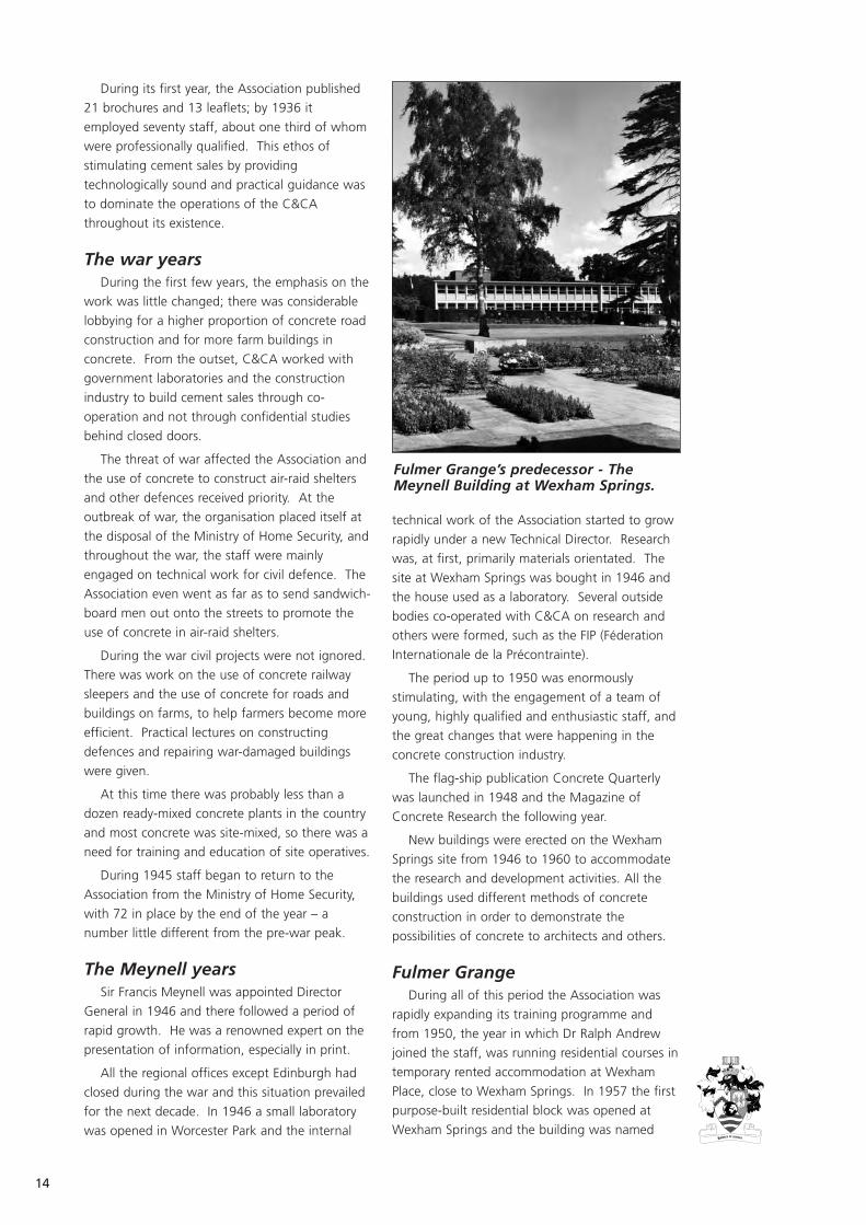
Fulmer GrangeDuring all of this period the Association was
rapidly expanding its training programme and
from 1950, the year in which Dr Ralph Andrew
joined the staff, was running residential courses in
temporary rented accommodation at Wexham
Place, close to Wexham Springs. In 1957 the first
purpose-built residential block was opened at
Wexham Springs and the building was named
Fulmer Grange’s predecessor - TheMeynell Building at Wexham Springs.

15
after the Director General, Sir Francis Meynell. In
that year there were 24 courses attended by 850
participants. This building remained the training
centre for ten years, until the opening of the
much larger facility at Fulmer Grange, which had
accommodation for 160 residential students.
When the Fulmer Grange complex was built
there was conflict with the local authority who
wanted to impose severe restrictions on the future
building programme of the Association. At one
time there was a threat of demolition of some of
the buildings and this affair was splashed across
the tabloid press. Fortunately, the then Director
General brought his diplomatic skills to bear and
local politicians were persuaded to reverse their
decision.
The existing house on the site became a social
centre for course participants, with a bar, snooker
room, library and sitting room, as well as offices
for the Director of Training and other members of
staff.
It is worth noting that the standard of
accommodation and catering were high – a
deliberate policy since participants on the courses
mainly remembered how well they were looked
after domestically; not that the lectures were
anything but good! Many of those who attended
courses fondly remember their welcome and the
care for their welfare. Early participants were
regularly introduced to the local hostelries, which
must have benefited significantly from the friendly
relationships developed with C&CA.
Colonel Buckmaster, who ran the British spy
service during the war, spent his childhood at
Fulmer Grange and was reputed to regularly run
home for tea when he was at Eton College, about
5 miles away. Later he returned to see what
C&CA had done to his old home and when
invited to go up to the attic, where the staff had
their offices, declined as he had never been to the
servants quarters before!
The golden yearsFurther buildings included the concrete
materials building, with the printing department
upstairs, workshops, stores and photographic
rooms in 1966 and the final one, the computer
block in 1970.
The Hon Leo Russell inherited a thriving
establishment when he took over as Director
General in 1958 and under his shrewd leadership
the Association continued to grow. The building
programme was completed, the regional offices
were re-opened in 1964. The headquarters
advisory staff was built up and research
flourished. Cement sales continued to grow,
reaching a peak of over 20 million tonnes per
annum by 1971. The cement industry was
A Fulmer Grange dormitory block and Fulmer Grange House.
16
changing; by 1958 there were 12 manufacturing
companies compared to the 20 pre-war. This
concentration was set to continue until there
were only three major cement producers in
Britain, who backed the C&CA when it merged
with the CMF in 1987 to form the British Cement
Association (BCA).
In materials research, hydration mechanisms
were seen as fundamental to understanding the
ways in which the properties of concrete could be
controlled to provide the characteristics required
by the user. The techniques established were to
prove invaluable when problems related to
concrete durability occurred. Mix design was
studied in depth, culminating in the joint
publication of Design of normal concrete mixes,
which demonstrated the close working and
mutual respect of the Association and
governmental organisations.
The Association campaigned to raise testing
standards and the testing of test machines,
including its comparative cube testing service.
An iso-thermal conduction calorimeter was
developed to study the effects of factors on the
heat output from cements. Creep and shrinkage
were studied from fundamental and practical
standpoints and the findings were used in British
and CEN Standards. The C&CA was always at the
forefront of development and research, including
high strength concrete and durability.
Many design rules were outlined or refined
following research in the structures division;
notably in bridge design and elements of
structural framed buildings, lightweight concrete,
fibre-reinforced concrete and crack widths.
The construction research section investigated
almost every aspect of concrete on the
construction site and even further – inspection
and maintenance and the re-use of concrete from
demolition. It lead on trench reinstatement, the
use of block paving , bridge corrosion from de-
icing salts, thermal insulation of houses and many
others.
TrainingOne of the original principal objectives of the
association was to inform and educate concrete
workers so that the best technology and practice
would be used to the ultimate benefit of the
cement manufacturing industry. This involved the
provision of lectures and demonstrations at every
level from the making and placing of concrete to
the latest knowledge, frequently based on the
Association’s research, on structural design,
construction practice or materials performance.
In the post-war years, the effort directed to
training grew and by the early 1950s courses of
several days duration were being held at Wexham
Place, together with practical demonstrations,
out-doors on site. The shell roof building
provided an area where these could be done
without the influence of bad weather. By 1954
the number of five-day courses had reached 17,
but there were many more shorter courses, and
lectures were being given throughout the country
by the technical and regional staff.
The first residential training centre, the Meynell
Building, opened in 1957. By 1961 there were 34
training courses a year, attended by over 1200
people, increasing to 40 courses during 1963.
This rapid rise in demand led to the acquisition of
the adjacent Fulmer Grange site and the
construction of the much larger residential
training facility that had 160 single bedrooms,
lecture and seminar rooms and a suite of
laboratories for demonstrations and hands-on
experience. By 1967 the number of courses run
per year reached 100 for the first time, ranging
from one to five days duration.
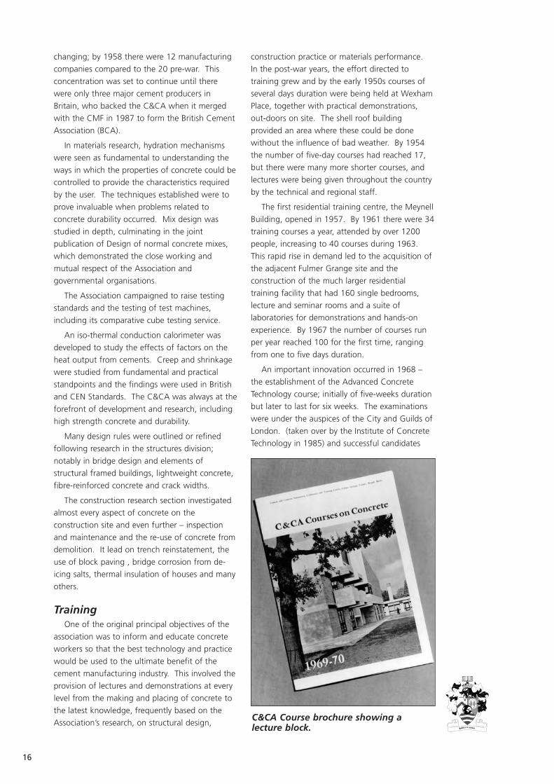
An important innovation occurred in 1968 –
the establishment of the Advanced Concrete
Technology course; initially of five-weeks duration
but later to last for six weeks. The examinations
were under the auspices of the City and Guilds of
London. (taken over by the Institute of Concrete
Technology in 1985) and successful candidates
C&CA Course brochure showing alecture block.
17
received a diploma. These diploma holders
founded the Association of Concrete
Technologists, which later became the Institute of
Concrete Technology. Participants on this course
were to come from many countries across the
world.
By 1979 over 50 000 participants had attended
C&CA courses and by 1985 this had jumped to
100 000, but by then there was a changing tide
in the industry and the demands for residential
courses began to decline. The Association, as
always, was ready to respond to change and they
had already introduced another innovation, the
correspondence course on ‘Concrete Technology
and Construction’. This proved highly successful
and in the first year 123 students took the course
and sat the City and Guilds examination. The
85% success rate considerably exceeded that for
the average candidate in the UK and overseas.
Sadly, the demand for residential courses
continued to fall and by 1987 a decision was
taken to close Fulmer Grange and to rely on
running training courses around the country.
During the next few years this policy seemed to
have been vindicated as there were more
participants attending the courses than in the
final years at Fulmer Grange. Many of the
training staff were retained in other divisions at
Wexham Springs and continued to provide the
main core of lecturers.
Training was a key undertaking by the BCA
during its early years but eventually it became
economically unviable and was handed over to
Thomas Telford Training in the mid-1990s.
The Advanced Concrete Technology course
continued at Imperial College in London for a few
years before moving to Nottingham University’s
campus. It is now a web-based course run from
the UK by Talent. Residential courses have been
held in Ireland and now run in South Africa and
Australia.
Some courses are still run by Thomas Telford
Training and by one or two individuals, as in-
house events.
Concrete Practice examinations are no longer
available from City and Guilds. Concrete
Technology and Construction (CT&C) distance
learning courses have suffered from lack of
funding but are being re-presented by a
combination of the National Construction College
at Bircham Newton and Isolearn in a more user-
friendly format. In recent times the Institute has
revised the range of syllabuses into four levels, to
reflect industry’s current training needs. Level 1
replaces Concrete Practice and occasional courses
are run for the examination provided by the
Institute, who are keen to ensure the continued
existence of all examination levels. Levels 2 and 3
are intended to replace CT&C – General Principles
and Practical Applications respectively and the
ACT will become Level 4.
As to the future, the merger of ICT with The
Concrete Society opens the door to a possible
expansion of concrete-related training activities.
ConclusionThose who took courses at Fulmer Grange
tend to remember their time there with nostalgia;
the food, the camaraderie and the lectures. Most
of the staff who were there at its closure in 1987
have now retired and it is difficult to envisage
how the valuable results it achieved will be
continued. The glimmer of hope is the occasional
reminiscence from a past student and a further
hope that he will have had an influence on those
following him.

18
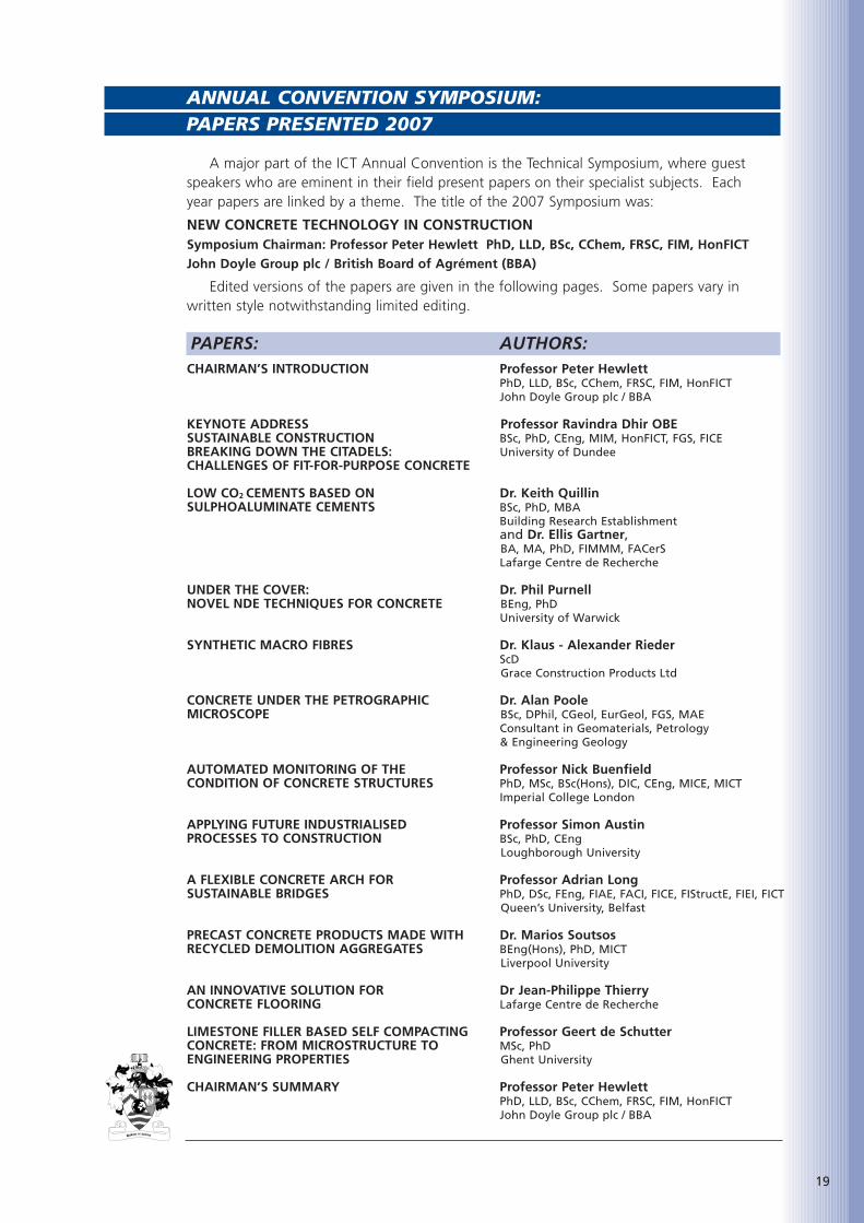
ANNUAL CONVENTION SYMPOSIUM: PAPERS PRESENTED 2007
PAPERS: AUTHORS:
A major part of the ICT Annual Convention is the Technical Symposium, where guestspeakers who are eminent in their field present papers on their specialist subjects. Each year papers are linked by a theme. The title of the 2007 Symposium was:
NEW CONCRETE TECHNOLOGY IN CONSTRUCTION Symposium Chairman: Professor Peter Hewlett PhD, LLD, BSc, CChem, FRSC, FIM, HonFICTJohn Doyle Group plc / British Board of Agrément (BBA)
Edited versions of the papers are given in the following pages. Some papers vary inwritten style notwithstanding limited editing.
CHAIRMAN’S INTRODUCTION Professor Peter Hewlett PhD, LLD, BSc, CChem, FRSC, FIM, HonFICTJohn Doyle Group plc / BBA
KEYNOTE ADDRESS Professor Ravindra Dhir OBESUSTAINABLE CONSTRUCTION BSc, PhD, CEng, MIM, HonFICT, FGS, FICEBREAKING DOWN THE CITADELS: University of DundeeCHALLENGES OF FIT-FOR-PURPOSE CONCRETE
LOW CO2 CEMENTS BASED ON Dr. Keith QuillinSULPHOALUMINATE CEMENTS BSc, PhD, MBA
Building Research Establishmentand Dr. Ellis Gartner,BA, MA, PhD, FIMMM, FACerSLafarge Centre de Recherche
UNDER THE COVER: Dr. Phil PurnellNOVEL NDE TECHNIQUES FOR CONCRETE BEng, PhD
University of Warwick
SYNTHETIC MACRO FIBRES Dr. Klaus - Alexander RiederScDGrace Construction Products Ltd
CONCRETE UNDER THE PETROGRAPHIC Dr. Alan PooleMICROSCOPE BSc, DPhil, CGeol, EurGeol, FGS, MAE
Consultant in Geomaterials, Petrology & Engineering Geology
AUTOMATED MONITORING OF THE Professor Nick BuenfieldCONDITION OF CONCRETE STRUCTURES PhD, MSc, BSc(Hons), DIC, CEng, MICE, MICT
Imperial College London
APPLYING FUTURE INDUSTRIALISED Professor Simon AustinPROCESSES TO CONSTRUCTION BSc, PhD, CEng
Loughborough University
A FLEXIBLE CONCRETE ARCH FOR Professor Adrian LongSUSTAINABLE BRIDGES PhD, DSc, FEng, FIAE, FACI, FICE, FIStructE, FIEI, FICT
Queen’s University, Belfast
PRECAST CONCRETE PRODUCTS MADE WITH Dr. Marios SoutsosRECYCLED DEMOLITION AGGREGATES BEng(Hons), PhD, MICT
Liverpool University
AN INNOVATIVE SOLUTION FOR Dr Jean-Philippe ThierryCONCRETE FLOORING Lafarge Centre de Recherche
LIMESTONE FILLER BASED SELF COMPACTING Professor Geert de SchutterCONCRETE: FROM MICROSTRUCTURE TO MSc, PhDENGINEERING PROPERTIES Ghent University
CHAIRMAN’S SUMMARY Professor Peter Hewlett PhD, LLD, BSc, CChem, FRSC, FIM, HonFICTJohn Doyle Group plc / BBA
19

20

It is my privilege to chair your
symposium today. We are here
to listen and learn. This, the
35th ICT Annual Symposium is
something of a landmark
technically.
I say that because there is much new concrete
technology that has been developed in the last
10 - 20 years and much being developed as we
meet. It is right that we should take stock and
adopt change where there is benefit and new
opportunity.
We have 11 presentations involving some 24
authors and co-authors within which there are at
least 8 Professors and 7 PhDs so we should not
be short on erudition. Within that mix we are
well endowed with engineers, and a sprinkling of
chemists, physicists, material scientists and
perhaps an engineering geologist.
The spread of subjects is wide and diverse,
demonstrating the adaptability of concrete on a
global scale.
We are presented with a technical feast today
so let us start the banquet with the keynote
address to be given by Professor Ravindra Dhir.
The subject is ‘Breaking down the Citadels:
Challenges of Fit-for-Purpose Concrete’.
21
CHAIRMAN’S INTRODUCTION
Professor Peter Hewlett PhD, LLD, BSc, CChem, FRSC, FIM, HonFICT
John Doyle Group plc / BBA

22

Ravindra Dhir is a professor at
the University of Dundee and
founding director of the
Concrete Technology Unit at
Dundee.
INTRODUCTIONConcrete has been the world’s premier
construction material since its first modern-day
use in the late 19th century, however, the past 30
years have seen a growing awareness amongst
engineers of the need to ensure durability in
concrete structures. This has arisen largely as a
result of the increasing incidence of premature
deterioration over the period and the substantial
repair and maintenance requirements that have
resulted[1]. While the specific problems
encountered have varied around the world, this
has very much become an issue of global
concern[2]. There has also been a growing
awareness of the importance of sustainability in
concrete construction and in particular of the
need for more effective and efficient use of virgin
and, as a result, recycled materials [3] and,
measures including landfill taxes and aggregate
levies have been introduced, at government level,
in order to promote and encourage these
practices[4].
Concrete is constantly evolving, and practices
and how the material is specified must also
evolve to ensure that it remains the sustainable
and competitive and durable solution to global
infrastructure needs. This paper examines the
current approach to concrete specification and
whether the citadels of concrete technology are
still valid for today’s concretes.
WHAT ARE THE CITADELS OF CONCRETE TECHNOLOGY?
Concrete specification for durability is primarily
governed by three limiting factors which have
been the stronghold of concrete performance for
many years:
• Water/cement ratio,
• Compressive strength,
• Cement content.
Since the patenting of Portland cement by
Joseph Aspdin in 1824, the relationship between
water, air and cement content have been
thoroughly researched. In 1896, Rene Féret
discovered a basic relationship between the ratios
of water and air plus cement to the strength of
concrete. Essentially this was a forerunner to
Abrams Law (1919) which is the governing
inverse relationship between water/cement ratio
and compressive strength still relevant today.
Developments in StandardsWater/cement ratio and compressive strength
have been present in the development of
standards from as far back as 1921[5]. The
introduction of somewhat vague guidance on the
three citadels appeared in CP114 during the
1940s and 50s, citing such terms as “1:2:4 mix
for a very good concrete” and that the water
content should ensure that concrete is
“sufficiently wet”. The standard did, however,
state that it was important to maintain the
water/cement ratio. As standards developed
through the 1960s (CP116) and 1970s (CP110),
the first links between the citadels and durability
were seen. Initially durability was linked to
strength and water/cement ratio; however,
minimum cement content was also seen as being
important. Exposure classes were also introduced
and linked directly to limiting factors. Further
developments in standards for concrete
specification in the 1980s and 1990s (BS8110
and BS5328)[6, 7] lead to the concept of trade-off
between concrete quality (defined by the limiting
factors) and cover depth to steel reinforcement.
However, changes are now taking place across
Europe with the introduction of EN 206-1[8] and
BS8500[9]. In recognition of how concrete has
changed over the past century, these standards
are now moving towards performance-based
specifications with specific degradation
mechanisms assigned to exposure classes.
23
KEYNOTE ADDRESS
SUSTAINABLE CONSTRUCTION BREAKING DOWN THE CITADELS:
CHALLENGES OF FIT-FOR-PURPOSE CONCRETE
Professor Ravindra Dhir OBE,
BSc, PhD, CEng, MIM, HonFICT, FGS, FICE
University of Dundee

24
However, the citadels remain with limiting factors
based on maximum water/cement ratio, minimum
compressive strength and minimum cement
content. The links between the citadels,
exposure conditions and cement type in
standards over the years are shown in Table1[10].
ARE THESE SUITABLE FOR 21st CENTURY CONCRETE?
The limiting factors of maximum water/cement
ratio, minimum compressive strength and
minimum cement content have served concrete
well for over 150 years with buildings such as
Weavers Mill, Swansea (Europe’s first reinforced
concrete structure) surviving for nearly 90 years.
However, there have been a number of instances
of failure through poor specification or
workmanship (eg the Montrose Bridge, built in
1930 and replaced in 2004 due to alkali silica
reaction, and the Tay Road Bridge, built in 1965
and undergoing continuous repairs since 1971).
The limiting factors have worked because they
are easy to specify and measure, can be
determined through the use of well established
and robust testing techniques and can provide
verifiable proof of what is in the concrete.
However, concrete has developed as a
material. Changes have taken place in the types
of constituent materials being used with additions
such as fly ash, ground granulated blastfurnace
slag, metakaolin and silica fume now being
specified in concrete. Recycled aggregates are
also being used as well as admixtures which
significantly modify fresh and hardened concrete
properties. There are now also increasing
demands on the engineering performance of
concrete, including self-compacting concrete,
pumpable and fibre-reinforced concrete as well as
requirements to adapt to changes in
functionalisation such as fire and impact
resistance, offshore environments, seismic loading
and use in nuclear applications.
Moreover, sustainability is now driving many
aspects of construction and concrete must assess
its carbon footprint by addressing important
issues such as embodied energy, use of natural
resources and absorbing recycled materials, whilst
at the same time exploiting some of its
environmentally friendly aspects such as thermal
mass.
MOVEMENT TOWARDS FITNESSFOR PURPOSE CONCRETE
As concrete evolves the question is raised as to
whether the limiting factor approach is suitable
or should we be moving toward ‘fit for purpose’
concrete? In order assess the suitability of the
citadels it is vital to understand the
interdependency of design and performance
when considering fitness for purpose. Design can
be defined as the conception of an idea to ensure
that a structure can withstand the demands
placed on it. Performance, on the other hand, is
a measure of the competency of the structure in
withstanding the demands and meeting the
expected level of service.
Defining DemandsTo determine whether we can achieve fitness
for purpose it is important to define clearly the
demands on concrete which must be met.
Table 1: Developments in standards for specifying concrete durability.
� � � � � � � �� � � � � � � �� � � � � � � �� � � � � � � �

Demands can come from a variety of areas, the
most obvious being structural integrity,
serviceability and durability. However, economics
will also play an important role and, as we move
towards a more sustainable society, embodied
energy, social impact and carbon footprint will
also be defining demands. It is also vital that the
demands are defined so that concrete can be
assessed for performance to see whether the
demands are being met.
Assessing PerformanceThe level of performance which is deemed to
be successful must also be defined clearly before
performance can be assessed. In terms of
concrete construction, there are a variety of levels
of performance which must be met and many of
these will depend on the demands which have
been defined. In current specification standards
(BS8500), performance levels are defined through
the length of time for the minimum intended
working life (eg 50 years, 100 years). However,
as sustainability is a key driver, performance levels
in the future may also be defined by such aspects
as the total carbon footprint of a concrete
structure, the embodied energy within the
structure or the whole life cost.
Once levels have been defined, we must be
able to measure performance in order to
determine whether they are being met. This is
currently where the limiting factor approach is
used; however, the use of other performance
indicators such as performance models,
sustainability indicators and life-cycle analysis
models may serve as better performance
measurement tools.
DO THE CITADELS ENSURE FITNESS FOR PURPOSE?
The increasing demands being placed on
concrete mean that ensuring the material meets
structural, durability, sustainability and economic
requirements is now paramount to the
construction industry. Although concrete as a
material has evolved significantly, the limiting
factors do little to encourage ‘fit for purpose’
concrete being achieved. Limiting the
water/cement ratio, compressive strength and
cement content may lead to prevention of the
use of sustainable materials such as recycled and
secondary aggregates. Figure 1 shows the
influence of recycled concrete aggregate (RCA)[11]
content on compressive strength; however,
although the current standards do not prevent
the use of recycled materials, the limiting factors
do not allow specifiers the freedom to use
combinations of recycled materials to achieve a
specific performance level.
Placing strict limitations on factors such as
strength, water/cement ratio and cement content
can lead to inhibitions on innovation. Novel
materials such as foamed concrete can often be
specified using factors outwith those in the
standards; however, the specifications limit their
use. Figure 2 (Page 26) examines the effect of
increasing fly ash content on concrete durability;
it shows that, as with many durability aspects,
increasing performance can be gained
independently of the water/cement ratio and/or
strength.
In addition, limitations placed on minimum
cement content can often inhibit increased
durability resistance as shown in Figure 3 (Page
26). This show that reducing the cement content
and optimising the fines content to obtain a
closed structure can lead to lower absorption,
lower permeability and a reduction in chloride
diffusion [12]. Although the limiting factors which
are currently placed on concrete do serve to
maintain a certain level of performance, they may
actually be preventing the development of more
sustainable, economic material.
CONCLUSIONConcrete as a material has changed
significantly over the past 150 years and
standards and specifications have also developed
to accommodate them. However, the industrial
climate is changing rapidly and a movement
towards ‘fit for purpose’ specifications is taking
place. Concrete now must respond to the
demands of a changing world such as (i) climate
change, (ii) carbon footprint issues, (iii) economic
25
Figure 1: Influence of recycled concreteaggregate content on compressivestrength and durability.

26
Figure 2: Influence of fly ash content on durability performance.
Figure 3: Effect on concrete durability of reducing cement content.
PFA Content, %* Assume Part 1 PFA price = 50% of PC price
D is the Chloride ion diffusion coefficient

pressures, (iv) client pressures, (v) increasing
demands from building insurance, and (vi) higher
performance requirements. The question remains
are we moving towards specifying fit for purpose
concrete or are we responding to these changing
demands?
Throughout Europe, there is a drive towards
probabilistic approaches to design in Eurocodes
and in particular performance based
specifications with the publication of the new fib
Model Code for Service Life Design[13]. This
initially focuses on chloride and carbonation-
induced corrosion as well as freeze-thaw attack;
however, can we be completely confident that we
can reliably populate the models for performance
specifications? We must now assess the test
methods in terms of measuring performance,
repeatability and reproduceability, sensitivity to
environmental conditions and cost, so that we
can standardise tools which will give us reliable
data to populate the models.
The current citadels of compressive strength,
water/cement ratio and cement content are in
danger of hindering the progress of concrete as
the world’s premier construction material.
Seismic shifts towards a performance-based
philosophy are now underway throughout
Europe; however, a focussed, coordinated
approach is required to ensure that concrete
emerges as the sustainable solution for new
construction projects.
New visions are required from the concrete
construction industry to embrace and drive the
changes needed in current specifications and
meaningful collaborative research and innovation
are paramount to success. Partnerships in
research across all communities on a large scale
are vital to ensure we move towards the creation
of a ‘fit for purpose’ approach to concrete
construction.
REFERENCES
1. The Concrete Society. Developments indurability design and performance-basedspecification of concrete. Concrete SocietySpecial Publication. CS 109, 1996, 69 pp.
2. SHARP, B.N. and SLATER, D. Design guidesand standards. Concrete in CoastalStructures. (Ed T.R. Allen), Thomas Telford,London, 1998.
3. Department of the Environment. MPG6Mineral planning guide for aggregatesprovision in England, HMSO, London, 1994.
4. UK Government. A better quality of life: astrategy for sustainable development in theUnited Kingdom. The Stationary Office,London, 1997.
5. Everyday Use of Portland Cement,Associated Portland Cement Manufacturers,1921
6. British Standards Institution. BS 8110: Part1. Structural use of concrete: Code ofpractice for design and construction.London, 1985 & 1997.
7. British Standards Institution. BS 5328: Part1. Concrete: Guide to specifying concrete.London, 1991 & 1997.
8. British Standard Institution. BS EN 206-1:Concrete – Part 1: Specification,performance, production and conformity.London, 2000.
9. British Standard Institution. BS 8500:Concrete – Complementary BritishStandard to BS EN 206-1 – Part 2.Specification for constituent materials andconcrete. London, 2002.
10. The Concrete Society. The influence ofcement content on the performance ofconcrete. Crowthorne, 2000, 48 pp.Report No CS125.
11. DHIR, R.K., PAINE, K., DYER, T.D. andTANG, M.C. Value-added recycling ofdomestic industrial and construction arisingsas concrete aggregate, ConcreteEngineering International, March 2004, Vol.8, No. 1, pp 43-48.
12. DHIR, R.K., MCCARTHY, M.J., TITTLE, P.A.J.and ZHOU, S. Role of cement content inspecifications for durability: cement contentinfluences. Proceedings of the Institution ofCivil Engineers., Structures and Buildings (Inpress), 2004.
13. FIB, “Model Code for Service Life Design ofConcrete Structures”, pp180, 2006.
27

28
Keith Quillin is a Principal
Consultant in the Centre for
Concrete Construction and has
worked at BRE since 1990. He
has particular expertise in
cement chemistry, concrete
durability and service life design and prediction of
concrete structures. Other work has included the
development of an environmental code of
practice for the use of pfa as a filling material for
stabilising disused mine workings. Keith has
worked on the long-term properties of
cementitious materials relevant to the
containment of radioactive and toxic waste and
has carried out research and modelling studies to
determine phase equilibria in the CaO-Al2O3-SiO2-
H2O system. Keith has an Honours degree in
Chemistry and a PhD in Physical Chemistry. He
also has an MBA from Henley Management
college.
Dr Ellis Gartner is Principal
Scientist at Lafarge Central
Research, near Lyon, France.
He obtained a PhD in Gas
Phase Reaction Kinetics from
the University of Cambridge in
1974 but his interest in
Construction Materials began at the BRE where
he worked for the three following years, (mostly
under the very tolerant supervision of Dr. Philip
Nixon!) In 1977 he joined the Portland Cement
Association (in Skokie, Illinois) as a Research
Chemist, later becoming Manager of Basic
Research. In 1985 he moved to the Washington
DC area to work in the Central Research
Laboratory of W. R. Grace and Co., where he led
a small research group that created much of
Grace’s new admixture technology (CBA, ADVA,
Eclipse, etc.) In 1996 he moved again, this time
to the Lafarge Central Research Laboratory, to
manage research in cement-admixture
interactions, a critical aspect of the early
development phase of Agilia self-placing
concretes. He is a Fellow of the American
Ceramic Society and the UK Institute of Materials,
and has over 50 scientific publications and 28
patents. His current main interests are in cement
hydration mechanisms and sustainable cement
and concrete technologies.
ABSTRACTThe production of clinkers rich in calcium
sulfoaluminate (CSA) requires less limestone and
less energy than the production of conventional
Portland cement clinkers. Consequently, CO2
emissions per unit of clinker are reduced.
Experimental results also show that CSA-based
cements can be formulated to produce durable
concretes with physical properties comparable to
those of common classes of Portland cement
concrete. Overall CO2 emissions with such
cements can be significantly lower than with
conventional cements based on Portland clinker.
Two main avenues of research were followed
with a view to balancing environmental impact,
manufacturing costs and physical performance:
1. Blends of calcium-sulfoaluminate-rich
cements with non-clinker materials such
as ground granulated blastfurnace slag
(ggbs) and calcium sulfate. Certain
blended cements of this type were found
to give concretes with good physical
properties. They were demonstrated to be
suitable for the manufacture of precast
concrete blocks,
2. Cements based on novel clinkers
containing activated belite, calcium
sulfoaluminate and calcium aluminoferrite.
Such clinkers can potentially be
manufactured from a wide range of raw
materials, emitting 20-25% less CO2 than
Portland cement clinker. Concrete
compressive strength development to 90
days was shown to be comparable with an
otherwise equivalent concrete made using
a conventional Portland cement (PC)
(42.5R).
However, developing new cements like these
for large scale use is an inherently slow process,
and a great deal more work is still required to:
• Confirm that such cements can be
manufactured industrially, with the desired
29
LOW-CO2 CEMENTS BASED ON CALCIUM SULFOALUMINATES
Dr Keith Quillin, BSc, PhD, MBA
Building Research Establishment and
Ellis Gartner, BA, MA, PhD, FIMMM, FACerS
Lafarge Centre de Recherche
30
CO2 emissions savings and low
environmental impact, and at an
acceptable cost
• Better establish the effects of
compositional and processing variables on
performance
• Optimise cements for performance in
various major use categories, in terms of
physical properties, raw materials
availability, manufacturing parameters, etc
• Develop the scientific understanding
necessary to explain the observed
performance, and thus to help predict the
effect of variations in conditions on such
performance
• Clearly establish the long term
performance of these materials in concrete
and provide data that will give users and
specifiers confidence in their durability
• Develop appropriate codes and standards
for their use in construction.
KEYWORDSCarbon dioxide, Calcium sulfoaluminate,
Belite, Durability, Compressive strength.
INTRODUCTIONGlobal cement manufacture (including both
‘pure’ and ‘blended’ Portland cements) has risen
from 594 million tonnes per annum in 1970 to
2284 million tonnes per annum in 2005 with
virtually all of this growth occurring in developing
countries. Global production is likely to increase
significantly over the coming decades as the
global population increases. Recent forecasts
have suggested that global cement production
could exceed 5 billion tonnes per annum by
2050.
Cement manufacture is energy intensive. The
raw materials must be finely ground and
homogenised, and then heated to about 1450ºC
to form Portland cement clinker. Upon cooling,
the hard nodules of clinker must then be finely
ground, with small amounts of other ingredients
such as gypsum, to make the finished cement .
Energy consumption as fuel and electricity
consequently represents about 65-70% of the
variable costs associated with Portland cement
manufacture [1],[2].
Cement manufacture also produces large
amounts of CO2 due directly to the calcination of
CaCO3 (about 1.2 tonnes of limestone are
required to produce one tonne of a typical
modern Portland cement clinker). The amount of
CO2 emitted per unit of Portland cement clinker
manufactured depends on a number of factors
such as clinker type, fuel and raw materials
compositions and the energy efficiency of the
specific kiln system. The amount of CO2
produced per unit of finished cement varies even
more, depending on cement composition (e.g.
content of clinker and non-clinker ingredients),
manufacturing efficiency, etc. For example, the
US Geological Survey quotes[3] a figure for the
USA of about 0.94 tonnes per tonne of Portland
cement clinker. Recent data[4] on global CO2
emissions from cement manufacture (including
the use of non-clinker ingredients) give an overall
average of 0.88 tonnes of CO2 per tonne of
cement. The same data indicate a value for
Europe of about 0.63 tonnes per tonne. These
data imply that about 2 Gt of CO2 per year are
currently emitted directly to the atmosphere due
to cement manufacture.
The pressure to reduce energy consumption
and CO2 emissions during cement manufacture
has led the industry to increase the extent to
which Portland clinker is substituted in
conventional cements by other ingredients that
are currently approved in the existing norms, such
as granulated blastfurnace slag (ggbs), pulverized
fuel ash (pfa), natural pozzolans and limestone.
However, until recently, there have been few
serious attempts to develop novel cements based
on alternative clinkers with intrinsically lower
manufacturing CO2 emissions than conventional
Portland cement clinkers.
A number of alternative cements have been
proposed to deal with perceived CO2 and energy
problems[5],[6],[7]. However, as well as
demonstrating appropriate physical properties
and durability when used in concrete, any
potential replacement cement must be based on
minerals available in quantities comparable to the
demand, and well-distributed world-wide.
Cements based on significantly less abundant
minerals are unlikely to be produced in quantities
large enough to have much impact on global CO2
emissions.
Some of the most promising alternative
cementing systems for general concrete
applications at ambient temperatures currently
appear to be those based at least in part on
calcium sulfates, the availability of which is
increasing due to the widespread implementation
of sulfur dioxide emission controls. These include
calcium sulfoaluminate (CSA) and belite-calcium
sulfoaluminate-ferrite (BCSAF) cements and

31
similar systems that make good use of the
potential synergies between hydrated calcium
silicates, sulfates and aluminates. Some such
cements have been normalised in China under
the generic name “The Third Cement Series”.
In this paper we report some encouraging
preliminary results obtained on two novel
cementing systems of this general type:
• CSA-rich clinkers blended with ggbs and
other non-clinker ingredients
• BCSAF clinkers which can be made in
conventional PC kilns.
BELITE-RICH CEMENTSBelite-rich cements can be made by burning
mixtures of limestone and clay in a similar process
to that used for PC manufacture. The theoretical
energy requirements and process CO2 emissions
for the manufacture of belite-rich cements are
lower than that for PC (the main hydraulic
component of which is alite, an impure form of
C3S).
The formation of a high percentage of alite in
clinker requires that a finely-ground and
homogenised mixture of raw materials be heated
to a minimum temperature of about 1400ºC in
the rotary kiln. However, belite, C2S, is formed
rapidly at above 1200ºC if the raw materials are
sufficiently finely ground and well-mixed, so
cements based mainly on belite can generally be
manufactured at significantly lower kiln
temperatures. Belite-based cements have a
further advantage over PC in that the amount of
CO2 produced by decarbonation is reduced. This
is because the CaO content of belite (65.1% by
weight) is lower than that of alite (73.7% by
weight). In fact, it is this lower CaO content that
really reduces the thermal energy required to
make belite, relative to alite. This is because the
decarbonation of limestone is highly
endothermic, and actually accounts for the
majority of the fuel consumption in a modern
energy-efficient cement kiln system. Differences
in maximum burning-zone temperature have only
an indirect effect on kiln thermal efficiency.
Belite-rich cements can produce concretes with
very good long term properties. However,
strength development is generally very slow in
comparison with alite-rich Portland cements due
to the inherently slow hydration of the usual
belite phase (C2S). In order to produce cements
suitable for most modern applications it is
therefore necessary to either produce a more
reactive form of belite or to add a more reactive
component to contribute to the early age
strength development.
The presence of Fe2O3 in the raw meal can
lead to the formation of ferrite (C4AF) and to the
partial substitution of Al2O3 in other alumina-rich
phases such as calcium sulfoaluminate. The
inclusion of higher levels of Fe2O3 increases the
range of raw materials that can be used in
manufacture and so has the potential to reduce
the cost. Fe2O3 also usually acts as a flux in the
clinkering process, which can help reduce the kiln
residence time.
The compositions of belite-based cements can
be altered through the inclusion of reactive
phases, such as calcium sulfoaluminate, C4A3S
(mineral name: yeelimite), that increase the early
strength. The reactive phase C4A3S (in some
cases together with CS and/or C4AF) hydrates to
produce ettringite as the main hydrate phase
responsible for the early strength. The belite
component hydrates more slowly and is
responsible for the long-term strength.
C4A3S can be formed in a cement kiln at
temperatures between about 1000ºC and
1300ºC. The production of 1 tonne of C4A3S
generates only 216 kg of CO2 from limestone
decarbonation if one assumes that its sulfate
originates from calcium sulfate in the raw mix. (If
this sulfate originates from the combustion of
sulfur in fuel and its reaction with lime, then this
figure increases slightly, to 288kg of CO2 per
tonne of C4A3S; but it is still a low value.)
A simple calculation for a belite-sulfoaluminate
cement (assumed to contain 38% belite and 35%
C4A3S together with calcite calcium aluminoferrite
and calcium sulphate) suggests that limestone
decarbonation would only produce about 300 kg
of CO2 per tonne of cement. However, CO2
emissions arising from energy consumption must
be added to these figures. Whilst it is not
possible to accurately determine CO2 savings
arising from any reductions in energy use prior to
carrying out manufacture on a large scale it is
reasonable to assume that, within limits, energy
use is proportional to CaCO3 content of the raw
feed. Consequently, if such clinkers can be
made in modern energy efficient (preheater) kiln
systems, overall CO2 emissions can be assumed to
be reduced roughly in proportion to the reduction
in process CO2 emissions.
EXPERIMENTALAn experimental programme was carried out
to assess the performance of concretes made
-
-
-
-
-
-
-

32
using various CSA-based cements. The mix
design used in each case was as follows:
Total binder content: 300 kg/m3
Free water: binder ratio: 0.55
Total aggregate: cement ratio: 6.1:1
20-10 mm Thames Valley 35%
10-5 mm Thames Valley 25%
5-0 mm Thames Valley 40%
No admixtures were used. Concretes were
subjected to a standard curing regime involving
24 hours curing in moulds under damped hessian
prior to storage in the following environments:
• Water at 20ºC
• Water at 5ºC
• Water at 38ºC
• Air (20ºC, 65% RH)
• External sheltered
• External unsheltered
• 4% CO2, 65% RH, 20ºC (accelerated
carbonation)
Compressive strength determinations were
carried out on 100 mm cubes in accordance with
BS1881: Part 116[8]. The hydrated phases present
in the samples were identified by X-ray
diffractometry (XRD), with a Siemens D500
diffractometer using Cu Ka radiation and
operating at 40 KV and 30 mA. Data were
accumulated over one scan of 2ø between 5º and
50º. Assignments of lines were made by
comparisons with JCPDS files. Conduction
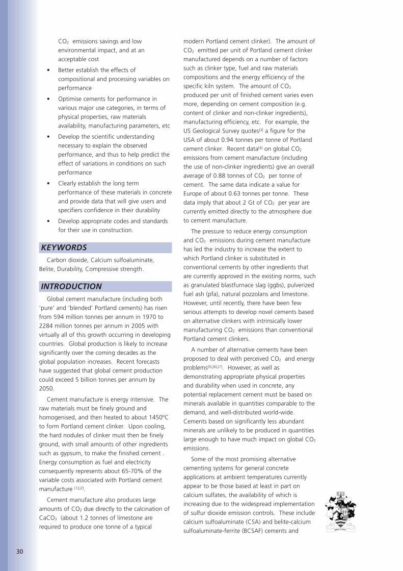
calorimetry was carried out using a Wexham
isothermal conduction calorimeter.
Carbonation depth was measured on 75 x 75
x 200 mm prisms made using the same mix
designs as used for compressive strength
development. Specimens for accelerated
carbonation were stored in water to 28 days
followed by 28 days conditioning at 20ºC and
65% RH prior to testing (carbonation occurred
over this period, as shown by the carbonation
depth at 0 days). The samples were then
exposed to a carbon dioxide enriched atmosphere
with a CO2 level of 4% at 20ºC and 65% RH.
Carbonation depths were measured at 2-weekly
intervals as described above. Specimens for
natural carbonation were cured under damp
Hessian and polythene to 1 day prior to placing in
the following exposure conditions:
a. Indoors at 65% RH and 20ºC
b. Outside sheltered
c. Outside unsheltered
Carbonation depths were determined by
spraying freshly fractured surfaces of concrete
specimens with a phenolphthalein indicator
solution and measuring the depth of the coloured
region at 5 points along each edge of the
specimen before averaging.
CSA-GGBS BLENDSThe properties of concretes made using a
range of CSA cements were studied. The
compositions of some of the cements used are
shown in Table 1. Theoretical CO2 savings
relative to pure PC concretes depend on the
composition but can be over 70% for the
compositions studied.
XRD analyses showed that the cements were
composed of various proportions of yeelimite,
belite, anhydrite and gypsum with small amounts
of calcite and possibly tricalcium aluminate.
Studies have included compressive strength
development and durability to 2 years. The CSA
cements were used neat and in blends with other
components such as ggbs, pfa and anhydrite.
Conduction calorimetry outputs on cements A to
D and B2 are shown in Figure 1.
Early age compressive strength data for
concrete made using neat CSA cements in water
at 20ºC are shown in Figure 2. 90-day strengths
are comparable with otherwise equivalent
concrete made using a typical
British PC (type CEM I 42.5R).
Strength development in CSA
cements blended with ggbs and
anhydrite are shown in Figure
3. From these results it is clear
that CSA-rich clinker on its own
is not a good activator for ggbs.
However, combinations of CSA
with calcium sulfate show good
strength development
Oxide content (wt%)
Oxide Cem A Cem B Cem C Cem D B2
SiO2 8.35 4.86 8.19 5.71 9.9
Al2O3 25.6 34.2 24.5 35.9 33.2
Fe2O3 2.84 2.46 2.70 2.47 1.0
CaO 42.0 40.7 42.4 40.9 47.0
SO3 13.8 12.0 13.1 9.30 7.9
Table 1: Compositions of CSA cements.
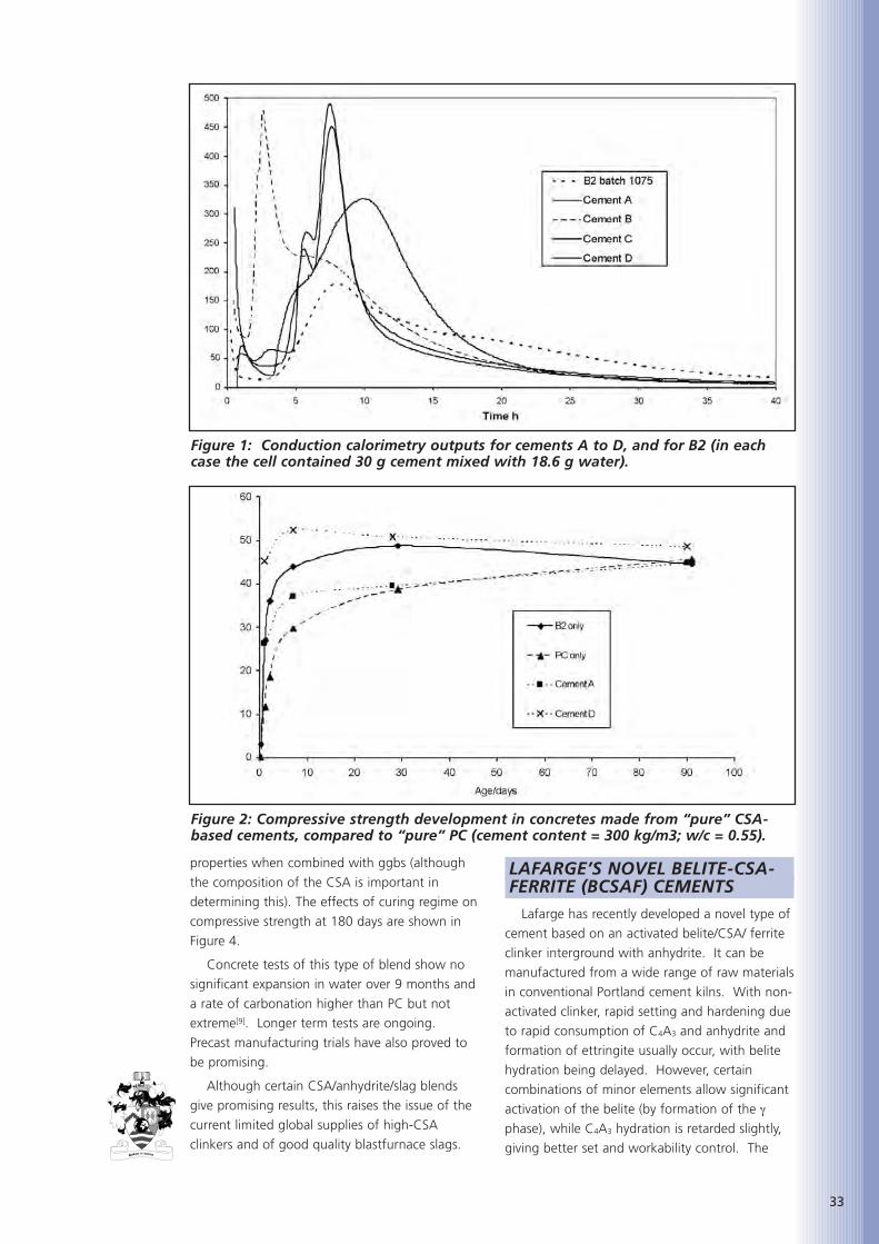
33
Figure 1: Conduction calorimetry outputs for cements A to D, and for B2 (in eachcase the cell contained 30 g cement mixed with 18.6 g water).
Figure 2: Compressive strength development in concretes made from “pure” CSA-based cements, compared to “pure” PC (cement content = 300 kg/m3; w/c = 0.55).
properties when combined with ggbs (although
the composition of the CSA is important in
determining this). The effects of curing regime on
compressive strength at 180 days are shown in
Figure 4.
Concrete tests of this type of blend show no
significant expansion in water over 9 months and
a rate of carbonation higher than PC but not
extreme[9]. Longer term tests are ongoing.
Precast manufacturing trials have also proved to
be promising.
Although certain CSA/anhydrite/slag blends
give promising results, this raises the issue of the
current limited global supplies of high-CSA
clinkers and of good quality blastfurnace slags.
LAFARGE’S NOVEL BELITE-CSA-FERRITE (BCSAF) CEMENTS
Lafarge has recently developed a novel type of
cement based on an activated belite/CSA/ ferrite
clinker interground with anhydrite. It can be
manufactured from a wide range of raw materials
in conventional Portland cement kilns. With non-
activated clinker, rapid setting and hardening due
to rapid consumption of C4A3 and anhydrite and
formation of ettringite usually occur, with belite
hydration being delayed. However, certain
combinations of minor elements allow significant
activation of the belite (by formation of the γ
phase), while C4A3 hydration is retarded slightly,
giving better set and workability control. The
34
Figure 5: Compressive strength development in equivalent concretes made usingLafarge’s BCSAF cement (B3) and PC (cement content = 300 kg/m3; w/c = 0.55).
Figure 4: Compressive strengths in different environments at 180 days.
Figure 3: Compressive strength development in concretes made fromCSA/ggbs/anhydrite blends, compared to a PC/slag blend (cement content = 300kg/m3; w/c = 0.55).
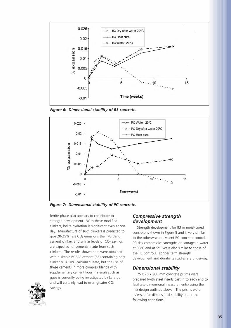
35
ferrite phase also appears to contribute to
strength development. With these modified
clinkers, belite hydration is significant even at one
day. Manufacture of such clinkers is predicted to
give 20-25% less CO2 emissions than Portland
cement clinker, and similar levels of CO2 savings
are expected for cements made from such
clinkers. The results shown here were obtained
with a simple BCSAF cement (B3) containing only
clinker plus 10% calcium sulfate, but the use of
these cements in more complex blends with
supplementary cementitious materials such as
ggbs is currently being investigated by Lafarge
and will certainly lead to even greater CO2
savings.
Compressive strengthdevelopment
Strength development for B3 in moist-cured
concrete is shown in Figure 5 and is very similar
to the otherwise equivalent PC concrete control.
90-day compressive strengths on storage in water
at 38ºC and at 5ºC were also similar to those of
the PC controls. Longer term strength
development and durability studies are underway.
Dimensional stability75 x 75 x 200 mm concrete prisms were
prepared (with steel inserts cast in to each end to
facilitate dimensional measurements) using the
mix design outlined above. The prisms were
assessed for dimensional stability under the
following conditions:
Figure 6: Dimensional stability of B3 concrete.
Figure 7: Dimensional stability of PC concrete.

36
1. Storage in water at 20ºC
2. Storage in air at 20ºC and 65% RH (after
28 days water curing at 20ºC)
3. Storage in water at 20ºC following heat
curing at 90ºC for 4 hours
The results are shown in Figure 6. Results for
PC concrete stored under similar conditions are
shown in Figure 7.
CarbonationB3 concrete carbonated more rapidly than the
PC control under accelerated carbonation
conditions. Carbonation depths of 6 mm and 3
mm were measured for B3 and PC concretes
respectively after 91 days. However, there was
little difference in the rate of natural carbonation
in dry and external sheltered environments after
91 days. Longer term tests are underway.
Future tests will examine steel corrosion risks
directly.
CONCLUSIONSIt is difficult to change cement manufacturing
technology to greatly reduce CO2 emissions
because few alternative raw materials are widely
available in sufficient quantities. Even if the
materials are available, transportation costs can
be high.
However, our results show that it is possible,
under the right conditions, to manufacture
cements having equivalent performance to
Portland cements but with significantly lower CO2
emissions per unit of clinker, which implies also
the possibility for lower CO2 emissions per unit
volume of concrete.
Cements based on C4A3 plus ferrites, calcium
sulfates and either ggbs or activated belite are a
promising option. They can tolerate high sulfate
contents and hydrate to form mainly ettringite,
C-S-H & AFm phases. Preliminary concrete tests
of two alternative approaches to this have shown
promising strength and durability results, but
much more work is needed to establish sufficient
data to allow for normalisation of such cements
and their acceptance in general construction
applications. In developing a new cement for
large scale use a number of key objectives would
need to be met:
1. CO2 emissions and energy consumption
from manufacture needs to be as low as
possible. Other emissions (e.g. NOx and
SOx) also need to be tightly controlled,
2. The cement must be fit for purpose when
used in concrete, mortar, etc.
For example:
• Concrete made using it needs to have
handling characteristics that are
appropriate for a high-volume
construction material. It must be
consistent with H&S legislation, be
readily mixable using conventional
concrete mixing equipment, have
handling and setting times that allow
easy placement, but yet gain strength at
a reasonable rate (under typical curing
conditions) so to allow subsequent work
to progress rapidly
• Characteristics such as strength
development, durability, etc., must be
comparable to those of existing
construction cements (particularly
Portland cements)
3. Raw materials must be cheap and readily
available locally. Ideally waste and by-
product materials from other sectors
should be consumed in making such
cements
4. Other processing costs also need to be
acceptable, such that the final cost of
such cements is low enough to be
competitive as a means of reducing
cement-related industrial CO2 emissions,
(as opposed, for example, to the proposed
separation of CO2 from cement plant
exhaust gases and its liquefaction for
underground sequestration).
Whilst it is to some degree possible to tailor
the properties of a cement to a particular
application, the aim here is to develop a material
for bulk use as with Portland cement.
Consequently, appropriate codes and standards
for a new class of cements will need to be
developed. This will require a major investment
in collecting and analysing appropriate data and
developing the codes and standards themselves.
REFERENCES
1. LIVESEY,P., Challenges for the cementindustry, p321 Concrete for environmentalenhancement and protection, ed.DHIR,R.K., and DYER,T.D., Spon, London,1996.
2. European cement association (Cembureau);‘Energy is a sensitive factor in cementmanufacture’; www.cembureau.be, 2000.

3. van OSS,H.G., ‘Background Facts and IssuesConcerning Cement and Cement Data’, USGeological Survey Open-File Report 2005-1152, 2005.
4. PRICE,L., & WORRELL,E., Global energy use,CO2 emissions and the potential forreduction in the cement industry, IEACement Energy workshop, Paris, September2006.
5. GARTNER,E., ‘Industrially InterestingApproaches to ‘Low CO2’ Cements’. Cem.Concr. Res. 34 [9] 1489–1498, 2004.
6. QUILLIN,K., ‘Low energy cements’, BREReport 421, 1999.
7. LAWRENCE,C.D., ‘The production of lowenergy cements’, in Lea’s Chemistry ofCement and Concrete, 4th Edition, Ed.HEWLETT,P.C., Arnold, London, 1998.
8. BS 1881: Part 116: 1983: Method fordetermination of compressive strength ofconcrete cubes, British Standards Institution,London, 1983.
9. QUILLIN,K., ‘Low carbon belite-calciumsulfoaluminate cements’, to be published2007.
37

38
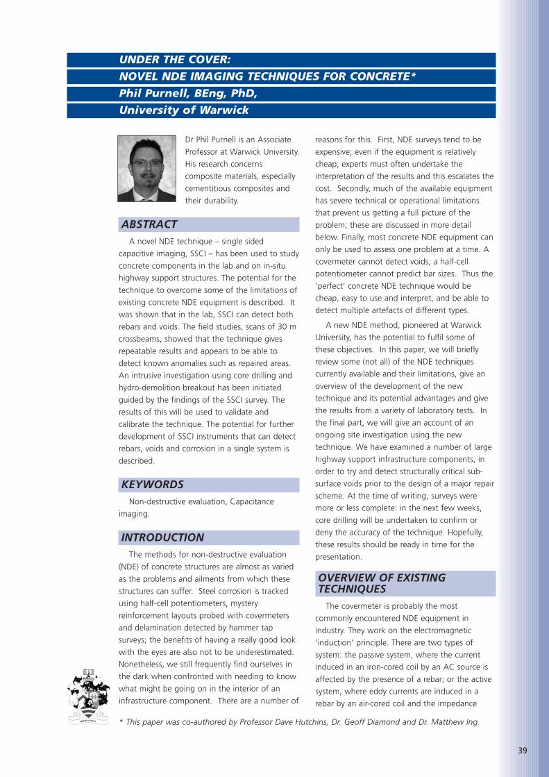
Dr Phil Purnell is an Associate
Professor at Warwick University.
His research concerns
composite materials, especially
cementitious composites and
their durability.
ABSTRACTA novel NDE technique – single sided
capacitive imaging, SSCI – has been used to study
concrete components in the lab and on in-situ
highway support structures. The potential for the
technique to overcome some of the limitations of
existing concrete NDE equipment is described. It
was shown that in the lab, SSCI can detect both
rebars and voids. The field studies, scans of 30 m
crossbeams, showed that the technique gives
repeatable results and appears to be able to
detect known anomalies such as repaired areas.
An intrusive investigation using core drilling and
hydro-demolition breakout has been initiated
guided by the findings of the SSCI survey. The
results of this will be used to validate and
calibrate the technique. The potential for further
development of SSCI instruments that can detect
rebars, voids and corrosion in a single system is
described.
KEYWORDSNon-destructive evaluation, Capacitance
imaging.
INTRODUCTIONThe methods for non-destructive evaluation
(NDE) of concrete structures are almost as varied
as the problems and ailments from which these
structures can suffer. Steel corrosion is tracked
using half-cell potentiometers, mystery
reinforcement layouts probed with covermeters
and delamination detected by hammer tap
surveys; the benefits of having a really good look
with the eyes are also not to be underestimated.
Nonetheless, we still frequently find ourselves in
the dark when confronted with needing to know
what might be going on in the interior of an
infrastructure component. There are a number of
reasons for this. First, NDE surveys tend to be
expensive; even if the equipment is relatively
cheap, experts must often undertake the
interpretation of the results and this escalates the
cost. Secondly, much of the available equipment
has severe technical or operational limitations
that prevent us getting a full picture of the
problem; these are discussed in more detail
below. Finally, most concrete NDE equipment can
only be used to assess one problem at a time. A
covermeter cannot detect voids; a half-cell
potentiometer cannot predict bar sizes. Thus the
‘perfect’ concrete NDE technique would be
cheap, easy to use and interpret, and be able to
detect multiple artefacts of different types.
A new NDE method, pioneered at Warwick
University, has the potential to fulfil some of
these objectives. In this paper, we will briefly
review some (not all) of the NDE techniques
currently available and their limitations, give an
overview of the development of the new
technique and its potential advantages and give
the results from a variety of laboratory tests. In
the final part, we will give an account of an
ongoing site investigation using the new
technique. We have examined a number of large
highway support infrastructure components, in
order to try and detect structurally critical sub-
surface voids prior to the design of a major repair
scheme. At the time of writing, surveys were
more or less complete: in the next few weeks,
core drilling will be undertaken to confirm or
deny the accuracy of the technique. Hopefully,
these results should be ready in time for the
presentation.
OVERVIEW OF EXISTING TECHNIQUES
The covermeter is probably the most
commonly encountered NDE equipment in
industry. They work on the electromagnetic
‘induction’ principle. There are two types of
system: the passive system, where the current
induced in an iron-cored coil by an AC source is
affected by the presence of a rebar; or the active
system, where eddy currents are induced in a
rebar by an air-cored coil and the impedance
39
UNDER THE COVER:
NOVEL NDE IMAGING TECHNIQUES FOR CONCRETE*
Phil Purnell, BEng, PhD,
University of Warwick
* This paper was co-authored by Professor Dave Hutchins, Dr. Geoff Diamond and Dr. Matthew Ing.
40
measured. Both systems can successfully
determine cover depth and rebar size in many
situations; but, if the rebar is deeper than about
60 mm into the concrete or the reinforcement
layout is congested then the covermeter can give
misleading readings, or fail to detect the steel at
all. If there are two or more layers of
reinforcement on top of one another, then the
covermeter will generally only detect the top layer
as lower layers are ‘screened’ e.g. [1].
Ultrasonic techniques have also been used to
assess concrete structures for many years [2]. The
time of flight of ultrasonic pulses – or, the speed
of sound in the concrete – can be correlated to
the strength of the concrete fairly well, either in
an absolute sense or more commonly in a relative
sense (i.e. looking for ‘low spots’ or ‘hot spots’).
To work properly, access is required to both sides
of a component so that a signal can be sent from
one transducer to another through the concrete.
This is not always possible. The transducers –
generally based on piezoelectric technology – also
need a good contact with the concrete, which
often requires surface preparation and couplants.
Imaging in concrete using ultrasound is very
difficult as it relies on the acoustic mismatch
between internal features, such as voids and
rebars, and the concrete. The problem is that this
mismatch tends to be similar to that between the
cement paste and the aggregate, causing
scattering of the signals and poor quality images[3]. Some success has been achieved at Warwick
with non-contact scanning ultrasound using
special transducers and powerful signal
processing [4], but from an imaging point of view
this is currently lab based.
More exotic techniques employ technology
based on ground-penetrating radar (GPR)
technology, as used in geophysical exploration.
Radar waves are reflected from boundaries
between materials with different dielectric
constant. Because of the wavelength of radar,
resolution is limited to around 100 mm for
commercial systems. Interpretation of the
complex 2-D colour plots is also something of an
art form and rather subjective [5,6].
The half-cell potentiometer can be used to
infer the probability of corrosion of the steel from
the surface of the concrete, since the degradation
is an electro-chemical process involving corrosion
of steel in an electrolyte (the fluids in the pores of
the concrete). A half-cell is basically a tube
containing an electrode in a saturated solution of
its own ions (usually silver and silver sulphate)
with one end sealed and the other plugged with
a porous material. The porous end is pressed
onto the surface of the concrete and the other
end is connected, via a high-impedance
voltmeter, to either the reinforcing steel (which
needs to be exposed) or a static ‘reference cell’.
An electrolytic connection is therefore made via
the half-cell and the pore fluid in the concrete to
the steel and the voltage measured. This is done
on a grid and a contour map produced. Areas of
high negative voltage gradient dV/dx – not high
voltage itself, as espoused by many practitioners
– indicate high corrosion current and thus areas
of likely steel degradation. Although widely used
and very successful with rapidly corroding steel,
in areas of slow corrosion or heavily carbonated
concrete it can be difficult to get sensible and
stable readings. Furthermore, breaking out of the
concrete cover is required to make the electrical
connection and/or calibrate the potential gradient
Figure 1: Schematic of the capacitive imaging transducer layout.
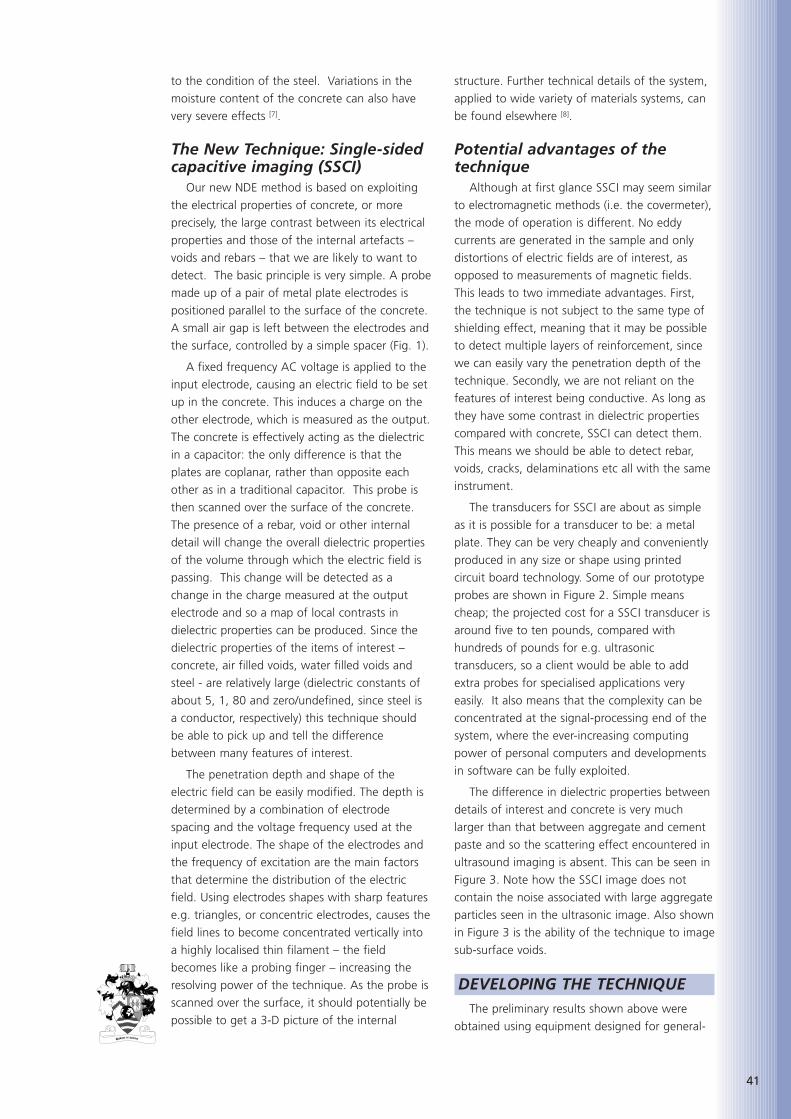
to the condition of the steel. Variations in the
moisture content of the concrete can also have
very severe effects [7].
The New Technique: Single-sidedcapacitive imaging (SSCI)
Our new NDE method is based on exploiting
the electrical properties of concrete, or more
precisely, the large contrast between its electrical
properties and those of the internal artefacts –
voids and rebars – that we are likely to want to
detect. The basic principle is very simple. A probe
made up of a pair of metal plate electrodes is
positioned parallel to the surface of the concrete.
A small air gap is left between the electrodes and
the surface, controlled by a simple spacer (Fig. 1).
A fixed frequency AC voltage is applied to the
input electrode, causing an electric field to be set
up in the concrete. This induces a charge on the
other electrode, which is measured as the output.
The concrete is effectively acting as the dielectric
in a capacitor: the only difference is that the
plates are coplanar, rather than opposite each
other as in a traditional capacitor. This probe is
then scanned over the surface of the concrete.
The presence of a rebar, void or other internal
detail will change the overall dielectric properties
of the volume through which the electric field is
passing. This change will be detected as a
change in the charge measured at the output
electrode and so a map of local contrasts in
dielectric properties can be produced. Since the
dielectric properties of the items of interest –
concrete, air filled voids, water filled voids and
steel - are relatively large (dielectric constants of
about 5, 1, 80 and zero/undefined, since steel is
a conductor, respectively) this technique should
be able to pick up and tell the difference
between many features of interest.
The penetration depth and shape of the
electric field can be easily modified. The depth is
determined by a combination of electrode
spacing and the voltage frequency used at the
input electrode. The shape of the electrodes and
the frequency of excitation are the main factors
that determine the distribution of the electric
field. Using electrodes shapes with sharp features
e.g. triangles, or concentric electrodes, causes the
field lines to become concentrated vertically into
a highly localised thin filament – the field
becomes like a probing finger – increasing the
resolving power of the technique. As the probe is
scanned over the surface, it should potentially be
possible to get a 3-D picture of the internal
structure. Further technical details of the system,
applied to wide variety of materials systems, can
be found elsewhere [8].
Potential advantages of thetechnique
Although at first glance SSCI may seem similar
to electromagnetic methods (i.e. the covermeter),
the mode of operation is different. No eddy
currents are generated in the sample and only
distortions of electric fields are of interest, as
opposed to measurements of magnetic fields.
This leads to two immediate advantages. First,
the technique is not subject to the same type of
shielding effect, meaning that it may be possible
to detect multiple layers of reinforcement, since
we can easily vary the penetration depth of the
technique. Secondly, we are not reliant on the
features of interest being conductive. As long as
they have some contrast in dielectric properties
compared with concrete, SSCI can detect them.
This means we should be able to detect rebar,
voids, cracks, delaminations etc all with the same
instrument.
The transducers for SSCI are about as simple
as it is possible for a transducer to be: a metal
plate. They can be very cheaply and conveniently
produced in any size or shape using printed
circuit board technology. Some of our prototype
probes are shown in Figure 2. Simple means
cheap; the projected cost for a SSCI transducer is
around five to ten pounds, compared with
hundreds of pounds for e.g. ultrasonic
transducers, so a client would be able to add
extra probes for specialised applications very
easily. It also means that the complexity can be
concentrated at the signal-processing end of the
system, where the ever-increasing computing
power of personal computers and developments
in software can be fully exploited.
The difference in dielectric properties between
details of interest and concrete is very much
larger than that between aggregate and cement
paste and so the scattering effect encountered in
ultrasound imaging is absent. This can be seen in
Figure 3. Note how the SSCI image does not
contain the noise associated with large aggregate
particles seen in the ultrasonic image. Also shown
in Figure 3 is the ability of the technique to image
sub-surface voids.
DEVELOPING THE TECHNIQUEThe preliminary results shown above were
obtained using equipment designed for general-
41

42
purpose use such as composites, aerospace
materials, food processing etc. Since we thought
that SSCI might be particularly useful in civil
applications, a project was set up to try and build
a prototype system. The project combined some
preliminary work by academics in the School with
a MEng final year group project, in both cases
pooling expertise from civil and electronic
engineering. Initially, the focus was on rebar
detection in the lab. In mid-2006, AmeyMouchel,
who provide long-term maintenance,
improvement and management services within
the transportation infrastructure sector, became
involved in the project and the focus shifted to
include detection of voids in-situ in highway
support structures. A number of structures in
their portfolio were identified where the
application of an SSCI survey might be of great
help as a pre-repair survey to ensure that before
deteriorated concrete is removed, any
construction voids that may exist within the
structure are detected and repaired, thus avoiding
any detrimental effect they would have on the
planned repair process. Areas identified as
potential voids or weak spots were to be core-
drilled in order to validate and calibrate the
technique. Time constraints were imposed owing
to access restrictions and contractual issues,
which meant that the laboratory and field trials
were forced to happen in parallel. As such, the
technique is still constantly evolving, and the
results presented here are preliminary; a snapshot
of progress to date.
Laboratory trialsTwo slabs were cast in the laboratory to act as
test beds for the prototype equipment. These are
shown in Figure 4. Both are 1m square and 120
Figure 2: Some prototype SSCI probes. Note sustainable recycling of packagingmaterials.
Figure 3: (a) Comparison between non-contact ultrasonic through transmissionimaging (top) and SSCI (bottom), 10 mm rebar embedded in 50 mm thick concreteslab. (b) Engineered hidden void in Thermalite block and corresponding SSCI scan.

mm thick, cast from C40 concrete with limestone
aggregate. Slab 1 was unreinforced, with a
stepped channel cast into the underside to
simulate a void. The channel ranged from 60 mm
to 90 mm deep (i.e. the cover over the void from
60 mm to 30 mm) with the step occurring in the
centre. Slab 2 was reinforced with two crossing
layers of 8 mm rebars, at 225 mm spacings, 100
mm below the surface (the stub ends of the bars
can be seen in the photos) i.e. the effective cover
was >90 mm, more than the normal 75 mm
maximum in Eurocode 2. Both slabs had lifting
steel cast in place (as can be seen in slab 2),
which was continuous along the length of the
slabs.
The prototype transducers were scanned over
the slabs using a 30 mm grid. Circuitry within the
system converted the charge signal to a voltage
and this was recorded. The results are shown in
figure 5. In the scan of slab 1 (left hand picture),
the wide dark area corresponds to the position of
the void, and the speckled grey areas at the
edges to the position of the lifting steel
reinforcement. Thus the technique appears to be
able to capture both rebars and voids in the same
pass. Some problems remain: the thin black
areas are artefacts caused by the contouring
process smoothing the transition from rebar areas
to plain areas, and the bulls-eye features in the
centre are caused by minor surface irregularities,
but these anomalies can be removed by image
processing: the raw results are presented here.
The scan for the reinforced slab is on the right. In
this case, solid grey areas correspond to
reinforcement and black/speckled areas to plain
concrete. The pattern of the crossing re-bars -
both layers – can clearly be seen and has been
detected at a depth of 100 mm, way beyond that
achievable with standard covermeters. Again, the
raw results are presented to demonstrate proof of
concept and image processing would produce
‘prettier’ images.
Both these results were taken using a 500 kHz
signal. Since then, modelling studies have
suggested that changing the frequency of the
scanning signal, as well as changing the depth of
penetration, also changes the sensitivity of the
technique to certain features; for example, high
43
Figure 4: Laboratory test slabs. Left: Slab 1, unreinforced slab with hidden steppedchannel. Right: Slab 2, Reinforced slab. The prototype equipment is fully containedwithin the toolbox shown.
Figure 5: SSCI results for laboratory slabs. Left: slab 1, Right: slab 2. Both scanstaken at 500 kHz.
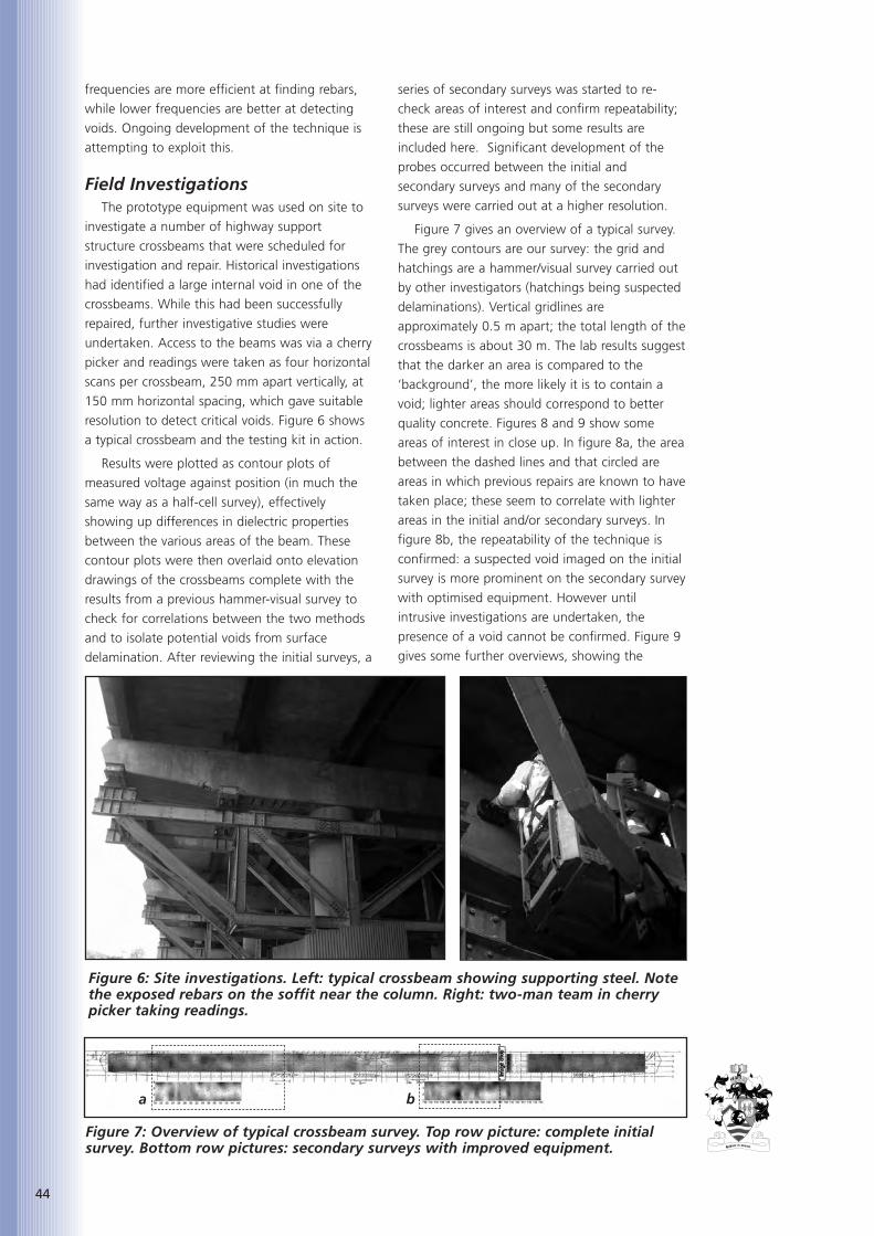
44
frequencies are more efficient at finding rebars,
while lower frequencies are better at detecting
voids. Ongoing development of the technique is
attempting to exploit this.
Field InvestigationsThe prototype equipment was used on site to
investigate a number of highway support
structure crossbeams that were scheduled for
investigation and repair. Historical investigations
had identified a large internal void in one of the
crossbeams. While this had been successfully
repaired, further investigative studies were
undertaken. Access to the beams was via a cherry
picker and readings were taken as four horizontal
scans per crossbeam, 250 mm apart vertically, at
150 mm horizontal spacing, which gave suitable
resolution to detect critical voids. Figure 6 shows
a typical crossbeam and the testing kit in action.
Results were plotted as contour plots of
measured voltage against position (in much the
same way as a half-cell survey), effectively
showing up differences in dielectric properties
between the various areas of the beam. These
contour plots were then overlaid onto elevation
drawings of the crossbeams complete with the
results from a previous hammer-visual survey to
check for correlations between the two methods
and to isolate potential voids from surface
delamination. After reviewing the initial surveys, a
series of secondary surveys was started to re-
check areas of interest and confirm repeatability;
these are still ongoing but some results are
included here. Significant development of the
probes occurred between the initial and
secondary surveys and many of the secondary
surveys were carried out at a higher resolution.
Figure 7 gives an overview of a typical survey.
The grey contours are our survey: the grid and
hatchings are a hammer/visual survey carried out
by other investigators (hatchings being suspected
delaminations). Vertical gridlines are
approximately 0.5 m apart; the total length of the
crossbeams is about 30 m. The lab results suggest
that the darker an area is compared to the
‘background’, the more likely it is to contain a
void; lighter areas should correspond to better
quality concrete. Figures 8 and 9 show some
areas of interest in close up. In figure 8a, the area
between the dashed lines and that circled are
areas in which previous repairs are known to have
taken place; these seem to correlate with lighter
areas in the initial and/or secondary surveys. In
figure 8b, the repeatability of the technique is
confirmed: a suspected void imaged on the initial
survey is more prominent on the secondary survey
with optimised equipment. However until
intrusive investigations are undertaken, the
presence of a void cannot be confirmed. Figure 9
gives some further overviews, showing the
Figure 7: Overview of typical crossbeam survey. Top row picture: complete initialsurvey. Bottom row pictures: secondary surveys with improved equipment.
a b
Figure 6: Site investigations. Left: typical crossbeam showing supporting steel. Notethe exposed rebars on the soffit near the column. Right: two-man team in cherrypicker taking readings.
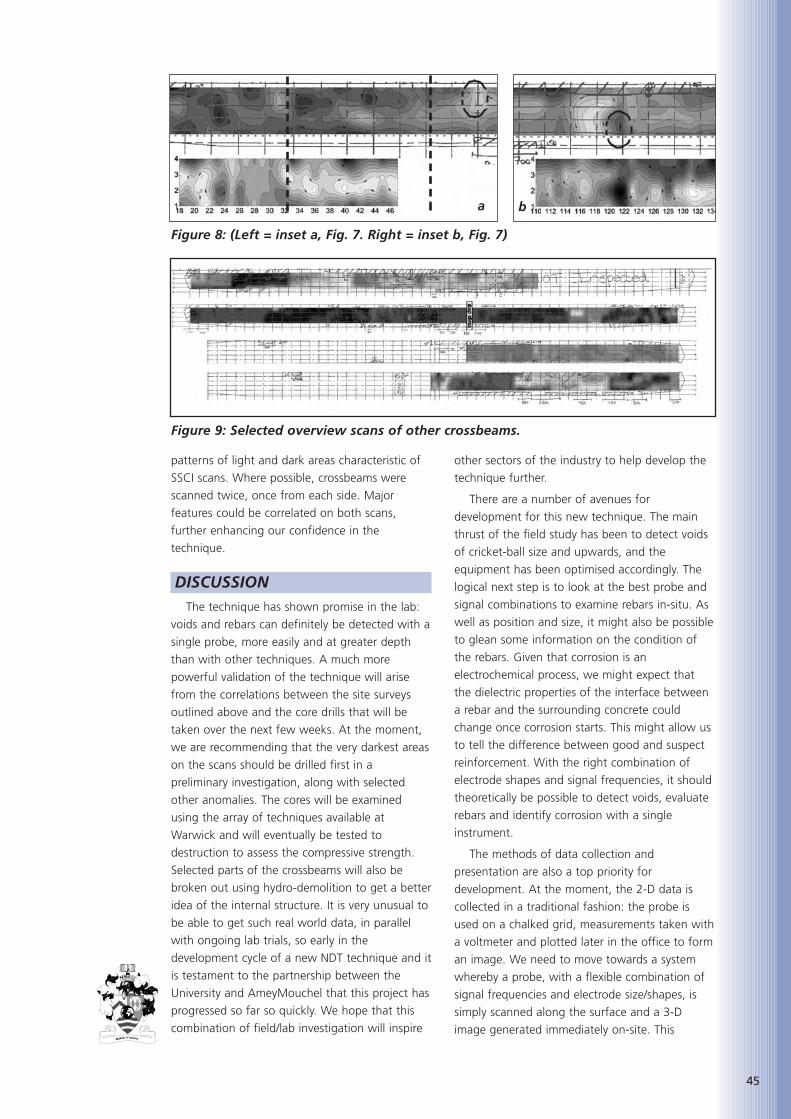
patterns of light and dark areas characteristic of
SSCI scans. Where possible, crossbeams were
scanned twice, once from each side. Major
features could be correlated on both scans,
further enhancing our confidence in the
technique.
DISCUSSIONThe technique has shown promise in the lab:
voids and rebars can definitely be detected with a
single probe, more easily and at greater depth
than with other techniques. A much more
powerful validation of the technique will arise
from the correlations between the site surveys
outlined above and the core drills that will be
taken over the next few weeks. At the moment,
we are recommending that the very darkest areas
on the scans should be drilled first in a
preliminary investigation, along with selected
other anomalies. The cores will be examined
using the array of techniques available at
Warwick and will eventually be tested to
destruction to assess the compressive strength.
Selected parts of the crossbeams will also be
broken out using hydro-demolition to get a better
idea of the internal structure. It is very unusual to
be able to get such real world data, in parallel
with ongoing lab trials, so early in the
development cycle of a new NDT technique and it
is testament to the partnership between the
University and AmeyMouchel that this project has
progressed so far so quickly. We hope that this
combination of field/lab investigation will inspire
other sectors of the industry to help develop the
technique further.
There are a number of avenues for
development for this new technique. The main
thrust of the field study has been to detect voids
of cricket-ball size and upwards, and the
equipment has been optimised accordingly. The
logical next step is to look at the best probe and
signal combinations to examine rebars in-situ. As
well as position and size, it might also be possible
to glean some information on the condition of
the rebars. Given that corrosion is an
electrochemical process, we might expect that
the dielectric properties of the interface between
a rebar and the surrounding concrete could
change once corrosion starts. This might allow us
to tell the difference between good and suspect
reinforcement. With the right combination of
electrode shapes and signal frequencies, it should
theoretically be possible to detect voids, evaluate
rebars and identify corrosion with a single
instrument.
The methods of data collection and
presentation are also a top priority for
development. At the moment, the 2-D data is
collected in a traditional fashion: the probe is
used on a chalked grid, measurements taken with
a voltmeter and plotted later in the office to form
an image. We need to move towards a system
whereby a probe, with a flexible combination of
signal frequencies and electrode size/shapes, is
simply scanned along the surface and a 3-D
image generated immediately on-site. This
45
a b
Figure 8: (Left = inset a, Fig. 7. Right = inset b, Fig. 7)
Figure 9: Selected overview scans of other crossbeams.
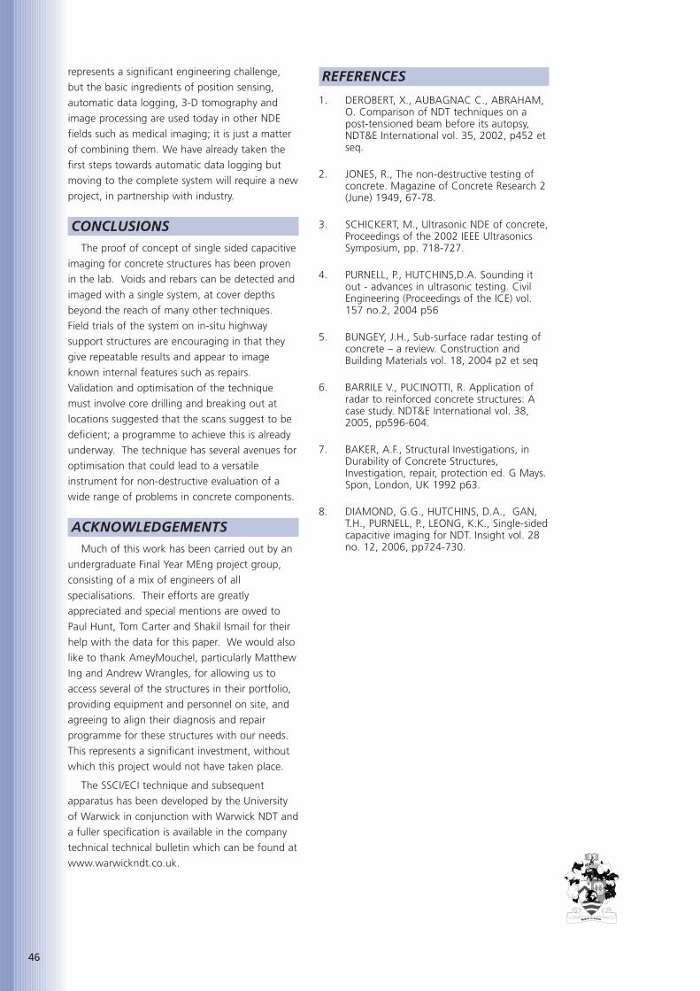
46
represents a significant engineering challenge,
but the basic ingredients of position sensing,
automatic data logging, 3-D tomography and
image processing are used today in other NDE
fields such as medical imaging; it is just a matter
of combining them. We have already taken the
first steps towards automatic data logging but
moving to the complete system will require a new
project, in partnership with industry.
CONCLUSIONSThe proof of concept of single sided capacitive
imaging for concrete structures has been proven
in the lab. Voids and rebars can be detected and
imaged with a single system, at cover depths
beyond the reach of many other techniques.
Field trials of the system on in-situ highway
support structures are encouraging in that they
give repeatable results and appear to image
known internal features such as repairs.
Validation and optimisation of the technique
must involve core drilling and breaking out at
locations suggested that the scans suggest to be
deficient; a programme to achieve this is already
underway. The technique has several avenues for
optimisation that could lead to a versatile
instrument for non-destructive evaluation of a
wide range of problems in concrete components.
ACKNOWLEDGEMENTSMuch of this work has been carried out by an
undergraduate Final Year MEng project group,
consisting of a mix of engineers of all
specialisations. Their efforts are greatly
appreciated and special mentions are owed to
Paul Hunt, Tom Carter and Shakil Ismail for their
help with the data for this paper. We would also
like to thank AmeyMouchel, particularly Matthew
Ing and Andrew Wrangles, for allowing us to
access several of the structures in their portfolio,
providing equipment and personnel on site, and
agreeing to align their diagnosis and repair
programme for these structures with our needs.
This represents a significant investment, without
which this project would not have taken place.
The SSCI/ECI technique and subsequent
apparatus has been developed by the University
of Warwick in conjunction with Warwick NDT and
a fuller specification is available in the company
technical technical bulletin which can be found at
www.warwickndt.co.uk.
REFERENCES
1. DEROBERT, X., AUBAGNAC C., ABRAHAM,O. Comparison of NDT techniques on apost-tensioned beam before its autopsy,NDT&E International vol. 35, 2002, p452 etseq.
2. JONES, R., The non-destructive testing ofconcrete. Magazine of Concrete Research 2(June) 1949, 67-78.
3. SCHICKERT, M., Ultrasonic NDE of concrete,Proceedings of the 2002 IEEE UltrasonicsSymposium, pp. 718-727.
4. PURNELL, P., HUTCHINS,D.A. Sounding itout - advances in ultrasonic testing. CivilEngineering (Proceedings of the ICE) vol.157 no.2, 2004 p56
5. BUNGEY, J.H., Sub-surface radar testing ofconcrete – a review. Construction andBuilding Materials vol. 18, 2004 p2 et seq
6. BARRILE V., PUCINOTTI, R. Application ofradar to reinforced concrete structures: Acase study. NDT&E International vol. 38,2005, pp596-604.
7. BAKER, A.F., Structural Investigations, inDurability of Concrete Structures,Investigation, repair, protection ed. G Mays.Spon, London, UK 1992 p63.
8. DIAMOND, G.G., HUTCHINS, D.A., GAN,T.H., PURNELL, P., LEONG, K.K., Single-sidedcapacitive imaging for NDT. Insight vol. 28no. 12, 2006, pp724-730.

Klaus-Alexander Rieder is a
principal scientist at W.R.
Grace, Cambridge, Mass. He
received his ScD in physics from
the Technical University of
Vienna, Austria, in 1995. He is
a member of ACI Committees 209, Creep and
Shrinkage in Concrete; 215, Fatigue of Concrete;
360, Design of Slabs on Ground; 446, Fracture
Mechanics; and 544, Fiber Reinforced Concrete.
He is also member of ASTM and currently
chairing task group E of C09.42. His research
interests include all durability aspects of concrete,
cracking of concrete, fracture mechanics, and the
development of high-performance fibres for
concrete applications. He has authored and co-
authored several papers and holds more than 10
patents in the field of fibre reinforcement.
ABSTRACTThis paper discusses various aspects of recent
developments in the field of synthetic macro
fibres. Different types of synthetic macro fibres
are introduced and their ability to increase the
post-cracking capacity of concrete. A simple
model is presented linking the material properties
of synthetic macro fibres to the material and
structural behaviour of concrete. In addition to
the short-term fibre material properties, some
long-term material property data are presented,
and their importance relative to the durability of
fibre-reinforced concrete is examined. Typical
applications of synthetic macro fibre reinforced
concrete are shown.
KEYWORDSSynthetic macro fibres, Steel fibres, Fibre-
reinforced concrete, Strength, Elastic modulus,
Toughness, Creep, Durability of cracked concrete,
Slab-on-ground, Steel decking.
INTRODUCTIONThe continued pressure to decrease costs
further for buildings and infrastructure, despite
the rising costs of raw materials and labour and
the creativity of architects in coming up with new
building designs, are only two reasons why the
construction industry is constantly looking for
new innovative materials and solutions. In the last
couple of years the well-documented rise in steel
prices, which is the second most used material
behind concrete, put even more pressure on
project managers and engineers to find ways to
reduce cost. Steel is used in beams, girders,
rebars, and mesh or fibres, just to name a few.
Steel fabric is mainly used to control drying
shrinkage and thermal cracking, for example in
slabs. To position the steel fabric properly in a
slab to provide optimum benefit to minimize
drying shrinkage cracking is very labour intense
and time consuming since the mesh needs to be
placed in the top third of the slab and thus needs
to be attached to closely spaced chairs. The
concrete also needs to be pumped from the
ready-mix truck since the already placed steel
fabric prevents the truck from discharging the
concrete where it is actually needed. It is also very
difficult to use laser screeds, which consolidate
and level the concrete and are especially efficient
when large concrete slabs are being poured.
The above-mentioned disadvantages have
lead to increased use of steel fibre reinforced
concrete, where deformed steel fibres are mixed
directly into concrete, replacing the steel fabric. It
has been demonstrated in the past through many
tests conducted by Universities [1, 2, 3, 4, 5, 6] and
thousands of completed projects that steel fibres
used at a sufficient dosage rate provide better or
equal crack control than mesh reinforcement in
applications such as industrial slabs. In addition to
the drying shrinkage crack control that steel fibre
reinforced concrete provides, it was shown that
the flexural capacity of slabs supported on
ground also increased. In order to achieve the
same benefit with mesh, a second layer of mesh
needs to be installed located in the bottom third
of the slab.
Despite the obvious benefits of steel fibre
reinforced concrete compared to conventional
steel fabric reinforcement, this technology also
has several shortcomings: to achieve an
homogeneous fibre distribution in the concrete,
most of the steel fibres need to be added to the
plastic concrete with special dispensers to avoid
fibre balling and nesting. When steel fibre
reinforced concrete needs to be pumped, there is
increased mechanical wear on the pump, hoses
47
SYNTHETIC MACRO FIBRES
Dr Klaus-Alexander Rieder, ScD,
Grace Construction Products Ltd

48
and finishing equipment and the pump pressure
needs to be increased. Although the high pH of
the concrete limits the corrosion of steel fibres
within the concrete, steel fibres close to the
concrete surface and in cracked concrete sections
will start to corrode, if the concrete gets in
contact with water, chlorides or acids. This effect
will lead to surface staining and in the worst-case
scenario in a cracked concrete section with a
crack width of more than 0.5 mm to a loss of
crack control capacity [7, 8, 9], unless of course
stainless steel fibres are used. Another potential
problem is related to steel fibres protruding out
of the concrete surface, which can be caused by
improper concrete placement or by concrete
spalling, abrasion or degradation. This can lead to
damage to vehicle tyres and could cause harm to
pedestrians and animals.
Synthetic Macro FibresRecent innovations in the field of fibre
reinforcement have led to the development of a
new class of fibres – the polymeric macro fibres,
which provide significant amounts of post-
cracking toughness or post-cracking flexural
strength to the concrete. This is in contrast to the
already well-accepted synthetic micro fibres,
which usually have a fibre diameter in the range
of 20 to 50 µm and are used only to control
plastic shrinkage cracking.
The polymeric macro fibres obviously cannot
corrode since most of them are made out of
polypropylene, polyethylene or a blend thereof.
They are usually much easier to handle than steel
fibres since the specific gravity of polypropylene is
about 12% that of steel. They maintain their
mechanical properties in high as well as in low
pH environments. The (equivalent) diameter of
these macro synthetic fibres ranges from 0.5 to 1
mm, with a tensile strength between 350 and
700 N/mm2. Depending on the fibre type used,
different dosage rates are needed to achieve a
residual flexural strength of at least 1 N/mm2. As
with steel fibre reinforced concrete, the more
synthetic macro fibres are needed to achieve a
certain toughness performance target, the higher
the impact of the fibres on the workability and
finishability of the concrete. Hence, the
workability needs to be restored using a
plasticizer or superplasticizer (NOT WATER), in the
concrete mix design.
In addition, due to the relatively low modulus
of elasticity of these polymeric macro fibres,
which is in the range of 3000 to 5000 N/mm2 (3
to 5 GPa), the performance of these fibres at
small crack openings is inferior to the
performance of deformed steel fibres, which have
a modulus of elasticity between 180 000 and 210
000 N/mm2 (180 to 210 GPa). However, since
most of the commercially available steel fibres are
designed to fail in fibre-pull-out mode (fibre pulls
out of the concrete matrix) rather than fibre-
failure mode, where the fibre breaks, the high
modulus of steel is only partly utilized when the
concrete starts to crack. This shortcoming does
not represent a big problem in many applications
such as shotcrete linings for mining tunnels, but it
is a significant shortcoming in applications such
as civil tunnels or slab on ground floors, where
large cracks are not acceptable to the engineer or
owner of the structure.
A New High PerformanceSynthetic Macro Fibre
Recently, a new synthetic macro fibre STRUX®
90/40 developed and patented by W R Grace
,and shown in Figure 1, was introduced to the
German construction market, where it recently
obtained DIBt (German Institute for Civil
Engineering) approval. The main components of
this polymeric fibre type (PP) are polypropylene
and polyethylene. This synthetic macro fibre's
mechanical and geometric properties are
significantly different from existing synthetic
macro fibres. The length of STRUX 90/40 is 40
mm with an aspect ratio (length divided by the
equivalent diameter) of 90 and a specific gravity
of 0.92. The fibre has a rectangular cross-section
with an average width of 1.40 mm and an
average thickness of 0.105 mm. The average
tensile strength of the fibre is 620 N/mm2 (MPa)
with a modulus of elasticity (chord modulus) of
9500 N/mm2 (9.5 GPa).
The ‘flat’ fibre design was chosen in part to
achieve a large fibre surface area to fibre volume
ratio in order to increase the mechanical bond
between the fibre and the cement paste. The
elastic modulus of this synthetic macro fibreFigure 1: Photograph of synthetic macrofibre STRUX 90/40.

nearly matches the elastic modulus of the cement
paste, where the fibre is embedded in, which
allows the fibre to transfer stresses across a crack
immediately after crack initiation has occurred.
Consequently, good crack control can be
achieved in concrete. Synthetic macro fibres with
either an insufficient bond or lower elastic
modulus first need to elongate before they are
able to transfer significant amounts of stresses
across widening cracks leading to larger crack
openings. This can be observed when measuring
the flexural performance (see Figure 2) using a
beam test set-up such as described in ASTM
C1609-06 [10] or JSCE-SF4 [11], which is being used
for designs of fibre reinforced concrete slab-on-
ground in CSTR 34 [12].
In the case of specimens containing lower
modulus crimped PP fibre, the stress drops
significantly right after the peak of the flexural
stress versus beam deflection. At larger beam
deflections, the post-cracking flexural strength
starts to increase again. At the same fibre
49
Figure 2: Flexural stress versus deflection curves measured according to ASTM C1609-06.
Figure 3: Flexural stress versus deflection curves measured according to DIN 1048 part 1.
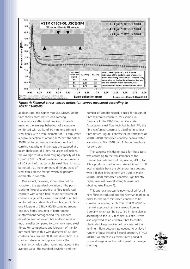
50
addition rate, the higher modulus STRUX 90/40
fibre shows much better load carrying
characteristics after initial cracking. It nearly
matches the average behaviour of a concrete
reinforced with 20 kg of 50 mm long crimped
steel fibres with a wire diameter of 1.3 mm. After
a beam deflection of around 0.25 mm the STRUX
90/40 reinforced beams maintain their load
carrying capacity until the tests are stopped at a
beam deflection of 3 mm. At larger deflections,
the average residual load carrying capacity of 4.6
kg/m3 of STRUX 90/40 matches the performance
of 40 kg/m3 of that particular steel fibre. It has to
be noted that there are many different types of
steel fibres on the market which all perform
differently in concrete.
One aspect, however, should also not be
forgotten: the standard deviation of the post-
cracking flexural strength of a fibre reinforced
concrete with a high fibre count per volume of
concrete is generally lower compared to a fibre
reinforced concrete with a low fibre count. Since
one kilogram of STRUX 90/40 contains around
185 000 fibres (resulting in better matrix-
reinforcement homogeneity), the standard
deviation even at lower fibre addition rates is
much smaller compared to commonly used steel
fibres. For comparison, one kilogram of the 50
mm steel fibre with a wire diameter of 1.3 mm
contains only around 2000 individual fibres. The
standard deviation is important since the
characteristic value which takes into account the
average value, the standard deviation and the
number of samples tested, is used for design of
fibre reinforced concrete, for example in
Germany. In the DBV (German Concrete
Association) steel fibre technical bulletin [13], the
fibre reinforced concrete is classified in various
fibre classes. Figure 3 shows the performance of
STRUX 90/40 reinforced concrete beams tested
according to DIN 1048 part 1: Testing methods
for concrete.
The concrete mix design used for these tests
was according to the requirements of the
German Institute for Civil Engineering (DIBt) for
‘Fibre products used as concrete additives’ [14] . If
local materials from the UK and/or mix designs
with a higher fines content are used to make
STRUX 90/40 reinforced concrete, significantly
higher residual flexural strength values are
obtained (see Figure 4).
This approval process is now required for all
new fibres introduced into the German market, in
order for the fibre reinforced concrete to be
classified according to EN 206. STRUX 90/40 is
the first approved synthetic macro fibre in
Germany which can be classified in fibre classes
according to the DBV technical bulletin. It was
also approved as an effective fibre to control
plastic shrinkage cracking of concrete. At the
minimum fibre dosage rate needed to achieve 1
N/mm2 of post cracking flexural strength, STRUX
90/40 is as effective as micro fibres added at
typical dosage rates to control plastic shrinkage
cracking.
Figure 4: Flexural stress versus deflection curves measured according to ASTM C1609-06.

During the DIBt approval process additional
tests were carried out, which confirmed the static
effectiveness of STRUX 90/40 in fibre reinforced
concrete particularly with regard to long-term
effectiveness. Some of these findings will be
presented later in this paper.
Large Scale Testing of ConcreteSlabs-on-Ground Reinforced withSTRUX 90/40
Before STRUX 90/40 was introduced
commercially to the North American market, a
large scale-testing programme was conducted at
the University of Illinois [15,16]. One purpose of that
study was to measure and compare the structural
response of plain, steel fibre, steel fabric and
STRUX 90/40 reinforced concrete slabs under
interior and edge loading conditions. Simply
supported small-scale beam tests had
demonstrated that STRUX 90/40 fibres could
significantly increase the post-cracking strength or
toughness of concrete matching the performance
of steel fibres [17]. However, the structural benefits
of STRUX 90/40 added to plain concrete were
unknown at that time. Since the fibre was
specially developed and optimized for such an
application, the structural benefits had to be
investigated.
Large-scale slab tests were also required to
determine if the beam toughness results could be
used to predict the flexural and ultimate capacity
of the synthetic STRUX 90/40 reinforced slabs in
the same manner as previous research had done
with steel fibres [1, 2, 5]. This type of testing was
essential for new fibre types since slab-on-
ground design codes such as the Technical Report
34 (TR 34) published by the Concrete Society [18]
are using beam toughness results such as the Re,3
value to predict the concrete slab’s ultimate
capacity and to calculate the required slab
thickness.
The slab dimensions selected for this study
were 2.2 m x 2.2 m x 0.127 m. The fully
supported slabs were tested under monotonic
loading conditions in displacement control to
better capture the response of the concrete
before and after cracking. Load-induced strains
were measured using embedded strain gauges,
which were placed at various locations before the
slabs were cast. The objectives of the strain
gauge placement were to measure compressive
and tensile stresses at the top and bottom of the
slab. Surface deflections of the concrete slabs
were measured by an array of Linear Variable
Displacement Transducers (LVDTs) as shown in
Figure 5, where the fully instrumented slab can
be seen before the load is being applied. Detailed
information and interpretation of all the test
results obtained from these experiments can be
found elsewhere [14, 15, 16] only a brief summary
and conclusions will be presented in this article.
The ultimate load carrying capacity of the plain
concrete slab is improved significantly with the
addition of STRUX 90/40. Compared to un-
reinforced concrete the flexural capacity under
centre load conditions increased by 25% for a
concrete slab reinforced with 3.0 kg/m3 STRUX
90/40 and 32% for a slab reinforced with 4.4
kg/m3 STRUX 90/40 (see Figure 6). STRUX 90/40
reinforced concrete also outperformed steel fabric
reinforced concrete (As=123 mm2/m).
51
Figure 5: Instrumented concrete slab supported on ground ready for testing.

52
The equivalent flexural strength ratio (Re,3)
indicated a similar increase in the flexural and
ultimate capacity of the fibre reinforced concrete
slabs over the plain concrete slab. Fibres help to
keep the slab in contact with the ground after
flexural cracking is reached enabling a better
redistribution of load. Embedded strain gauges
further confirmed that the load carrying capacity
of the fibre reinforced concrete slabs was
distributed over a larger area before flexural
cracking and thus allowed for a higher flexural
and ultimate capacity relative to the plain and
mesh reinforced concrete slabs.
The equivalent flexural strength ratio (Re,3)
indicated a similar increase in the flexural and
ultimate capacity of the fibre reinforced concrete
slabs over the plain concrete slab. Fibres help to
keep the slab in contact with the ground after
flexural cracking is reached enabling a better
redistribution of load. Embedded strain gauges
further confirmed that the load carrying capacity
of the fibre reinforced concrete slabs was
distributed over a larger area before flexural
cracking and thus allowed for a higher flexural
and ultimate capacity relative to the plain and
mesh reinforced concrete slabs. Figure 7 shows a
failure cracking pattern for a concrete slab
reinforced with STRUX 90/40 (a) and plain
concrete slab (b).
The synthetic macro fibre reinforced slabs and
the steel fibre reinforced slabs had overall similar
fracture behaviour. The load-deflection curves
also indicated that the structural ductility of the
synthetic macro and steel fibre slabs was similar.
Synthetic macro fibres as well as steel fibres did
not increase the tensile capacity of the concrete
slabs, which was consistent with findings from
previously published reports.
The findings from this study confirmed that
the post-cracking flexural strength measured on a
relatively small beam could be used to predict the
Figure 6: Load versus centre slab deflection curves of plain concrete, steel fabric andSTRUX 90/40 reinforced concrete slabs.
Figure 7: Cracking pattern of slabs: a) STRUX 90/40 reinforced concrete,b) plain concrete.

structural performance of STRUX 90/40 as well as
steel fibre reinforced concrete slabs-on-ground.
Since then many hundreds of jobs which utilized
STRUX 90/40 in lieu of conventional steel fabric
or fibres in slab-on-ground applications have
been completed successfully worldwide. A
summary of applications where STRUX 90/40 has
been used is presented at the end of this paper.
Long-Term Behaviour of STRUX90/40 Reinforced Concrete
As mentioned before, during the DIBt approval
process there was a special focus and
investigation on the long-term properties of
synthetic macro fibre reinforced concrete. Since
concrete floors are the main application for
STRUX 90/40, this paper will focus on the
findings relevant to that application. In general, it
has been found that polypropylene is very stable
in the concrete environment. Tensile strength
measurements of synthetic micro fibres
embedded for more than 30 years in concrete
showed minimal loss of strength compared to its
initial value. Accelerated ageing tests can be
performed such as the one described in
Acceptance Criteria for Concrete with Synthetic
Fibres (AC 32), which was published by the ICC
evaluation service. These tests confirmed that
STRUX 90/40 reinforced concrete maintains its
toughness performance long-term. It should be
noted that the above-mentioned evaluation does
not include testing of cracked fibre reinforced
concrete specimens under sustained load.
In the past, there was limited information
available about this topic; neither steel fibre
reinforced concrete nor synthetic macro fibre
reinforced concrete has been tested extensively to
determine the creep coefficient of cracked fibre
reinforced concrete (FRC). Recent studies
conducted by Bernard [19] on pre-cracked round
fibre reinforced panels, which he subjected to
various amounts of sustained loading, showed
that the creep coefficient of steel and STRUX
90/40 reinforced shotcrete were comparable.
However, another type of synthetic macro fibre
exhibited a significant amount of creep during
the test period. MacKay et al. [20] conducted a
study on creep of steel as well as synthetic macro
fibre reinforced concrete based on cracked
beams. The synthetic macro fibre investigated in
this programme had an elastic modulus of about
5 to 6 GPa. Although this macro fibre did not
creep as much as the one Bernard investigated,
the authors found that the creep coefficient of
steel fibre reinforced concrete investigated was
about 50% of that of synthetic macro fibre
reinforced concrete.
In 2005 an initiative was started to revise the
existing Guideline: ´Fibre Reinforced Concrete’
published by the Austrian Society for Concrete
and Construction Technology. It was agreed to
evaluate a standardized test procedure to
measure the creep behaviour of steel and
synthetic macro fibre reinforced concrete. With
the financial support of several fibre suppliers, a
testing programme was initiated. In order to
further investigate the difference in creep
behaviour between steel fibre and STRUX fibre
reinforced concrete, W R Grace started a test
programme to compare the creep of both
materials based on the recommendations of the
Austrian fibre committee.
Beams were cast at the Grace research
laboratory in Cambridge, Massachusetts, USA. A
typical floor mix design was used with a cylinder
compressive strength between 35 and 40 MPa.
STRUX 90/40 was dosed at 2.0 kg/m3, while 20
kg/m3 of a 60 mm long hooked end steel fibres
were added to the concrete. Since these were the
first tests of a larger series, the dosage rates were
not selected based on obtaining similar residual
load carrying capacities, but starting the tests
with the lowest recommended fibre dosage rates.
The 150 mm x 150 mm x 550 mm beams were
cured for 28 days in lime-saturated water before
being tested in four-point bending. Instead of a
final beam deflection of 3.0 mm, the test was
stopped at a beam deflection of 1.75 mm. In
addition, the relaxation of load response of the
cracked fibre reinforced concrete specimen was
recorded to determine the amount of elastic
energy stored in the specimen at a deflection of
1.75 mm. The specimen was then carefully
removed from the testing machine. Three
specimens of each fibre type with approximately
the same amount of residual flexural strengths
were selected and placed in a specially designed
loading frame shown in Figure 8. The calibrated
loading frame was loaded with weights until
50% of the residual flexural load carrying
capacity was reached.
This value was chosen by the Austrian fibre
committee as a starting value for the evaluation
of the creep behaviour of cracked fibre reinforced
concrete, because this stress represents the
maximum stress in the serviceability state, which
will occur in a concrete section according to the
current Austrian design guideline for fibre
reinforced concrete. The load is applied in four
53
54
point bending configuration and the beam
deflection is measured with a mechanical dial
gauge. Figure 9 shows the average deflection (in
mm) under sustained load over time of the two
fibre reinforced materials.
The elastic part of the deflection, which was
measured before, was subtracted from the long-
term creep measurement. As can be seen from
these results, both fibre materials exhibit similar
long-term creep behaviour. The deflection of the
STRUX reinforced concrete beams increases more
in the first couple of hours compared to the steel
fibre reinforced concrete beams. After that the
slope of the curves are nearly identical. Creep
measurement of these samples has been ongoing
for one year and will be continued. In the
meantime, a second creep frame has been
constructed so more tests can be conducted at
the same time.
Contrary to the common belief that steel fibre
reinforced concrete cannot creep since steel has a
low coefficient of creep, the results obtained so
far show that indeed cracked steel fibre
reinforced concrete does creep. This is not caused
by creep of the steel itself but by slow pull-out of
steel fibres out of the concrete matrix and the
interface which creeps. For synthetic macro fibres,
a combination of creep of the fibre material as
Figure 8: Loading frame to measure creep of cracked fibre reinforced concrete beams
Figure 9: Increase of beam deflection under sustained load (without elastic part).
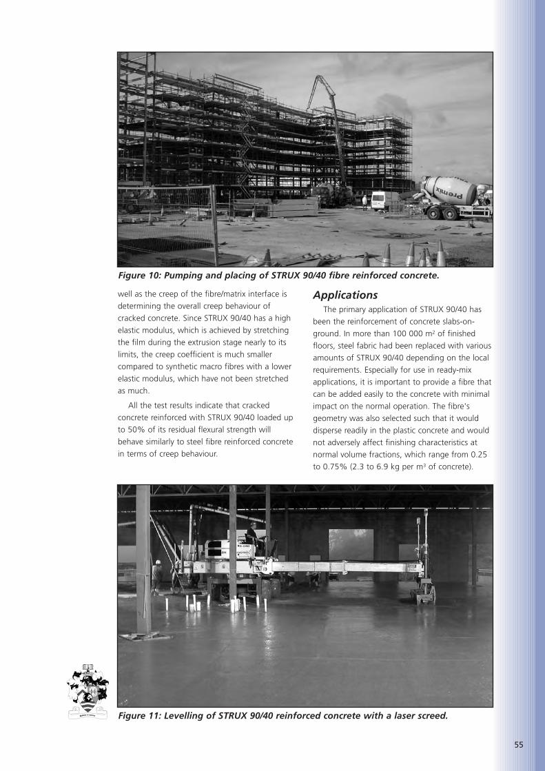
well as the creep of the fibre/matrix interface is
determining the overall creep behaviour of
cracked concrete. Since STRUX 90/40 has a high
elastic modulus, which is achieved by stretching
the film during the extrusion stage nearly to its
limits, the creep coefficient is much smaller
compared to synthetic macro fibres with a lower
elastic modulus, which have not been stretched
as much.
All the test results indicate that cracked
concrete reinforced with STRUX 90/40 loaded up
to 50% of its residual flexural strength will
behave similarly to steel fibre reinforced concrete
in terms of creep behaviour.
ApplicationsThe primary application of STRUX 90/40 has
been the reinforcement of concrete slabs-on-
ground. In more than 100 000 m2 of finished
floors, steel fabric had been replaced with various
amounts of STRUX 90/40 depending on the local
requirements. Especially for use in ready-mix
applications, it is important to provide a fibre that
can be added easily to the concrete with minimal
impact on the normal operation. The fibre's
geometry was also selected such that it would
disperse readily in the plastic concrete and would
not adversely affect finishing characteristics at
normal volume fractions, which range from 0.25
to 0.75% (2.3 to 6.9 kg per m3 of concrete).
55
Figure 10: Pumping and placing of STRUX 90/40 fibre reinforced concrete.
Figure 11: Levelling of STRUX 90/40 reinforced concrete with a laser screed.
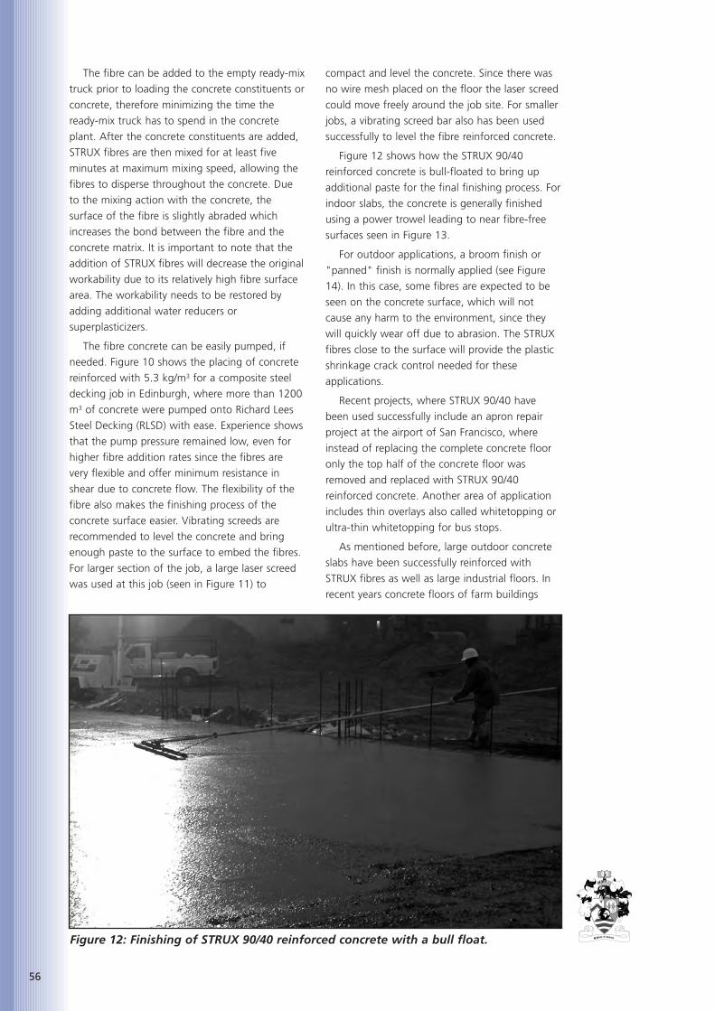
56
The fibre can be added to the empty ready-mix
truck prior to loading the concrete constituents or
concrete, therefore minimizing the time the
ready-mix truck has to spend in the concrete
plant. After the concrete constituents are added,
STRUX fibres are then mixed for at least five
minutes at maximum mixing speed, allowing the
fibres to disperse throughout the concrete. Due
to the mixing action with the concrete, the
surface of the fibre is slightly abraded which
increases the bond between the fibre and the
concrete matrix. It is important to note that the
addition of STRUX fibres will decrease the original
workability due to its relatively high fibre surface
area. The workability needs to be restored by
adding additional water reducers or
superplasticizers.
The fibre concrete can be easily pumped, if
needed. Figure 10 shows the placing of concrete
reinforced with 5.3 kg/m3 for a composite steel
decking job in Edinburgh, where more than 1200
m3 of concrete were pumped onto Richard Lees
Steel Decking (RLSD) with ease. Experience shows
that the pump pressure remained low, even for
higher fibre addition rates since the fibres are
very flexible and offer minimum resistance in
shear due to concrete flow. The flexibility of the
fibre also makes the finishing process of the
concrete surface easier. Vibrating screeds are
recommended to level the concrete and bring
enough paste to the surface to embed the fibres.
For larger section of the job, a large laser screed
was used at this job (seen in Figure 11) to
compact and level the concrete. Since there was
no wire mesh placed on the floor the laser screed
could move freely around the job site. For smaller
jobs, a vibrating screed bar also has been used
successfully to level the fibre reinforced concrete.
Figure 12 shows how the STRUX 90/40
reinforced concrete is bull-floated to bring up
additional paste for the final finishing process. For
indoor slabs, the concrete is generally finished
using a power trowel leading to near fibre-free
surfaces seen in Figure 13.
For outdoor applications, a broom finish or
"panned" finish is normally applied (see Figure
14). In this case, some fibres are expected to be
seen on the concrete surface, which will not
cause any harm to the environment, since they
will quickly wear off due to abrasion. The STRUX
fibres close to the surface will provide the plastic
shrinkage crack control needed for these
applications.
Recent projects, where STRUX 90/40 have
been used successfully include an apron repair
project at the airport of San Francisco, where
instead of replacing the complete concrete floor
only the top half of the concrete floor was
removed and replaced with STRUX 90/40
reinforced concrete. Another area of application
includes thin overlays also called whitetopping or
ultra-thin whitetopping for bus stops.
As mentioned before, large outdoor concrete
slabs have been successfully reinforced with
STRUX fibres as well as large industrial floors. In
recent years concrete floors of farm buildings
Figure 12: Finishing of STRUX 90/40 reinforced concrete with a bull float.
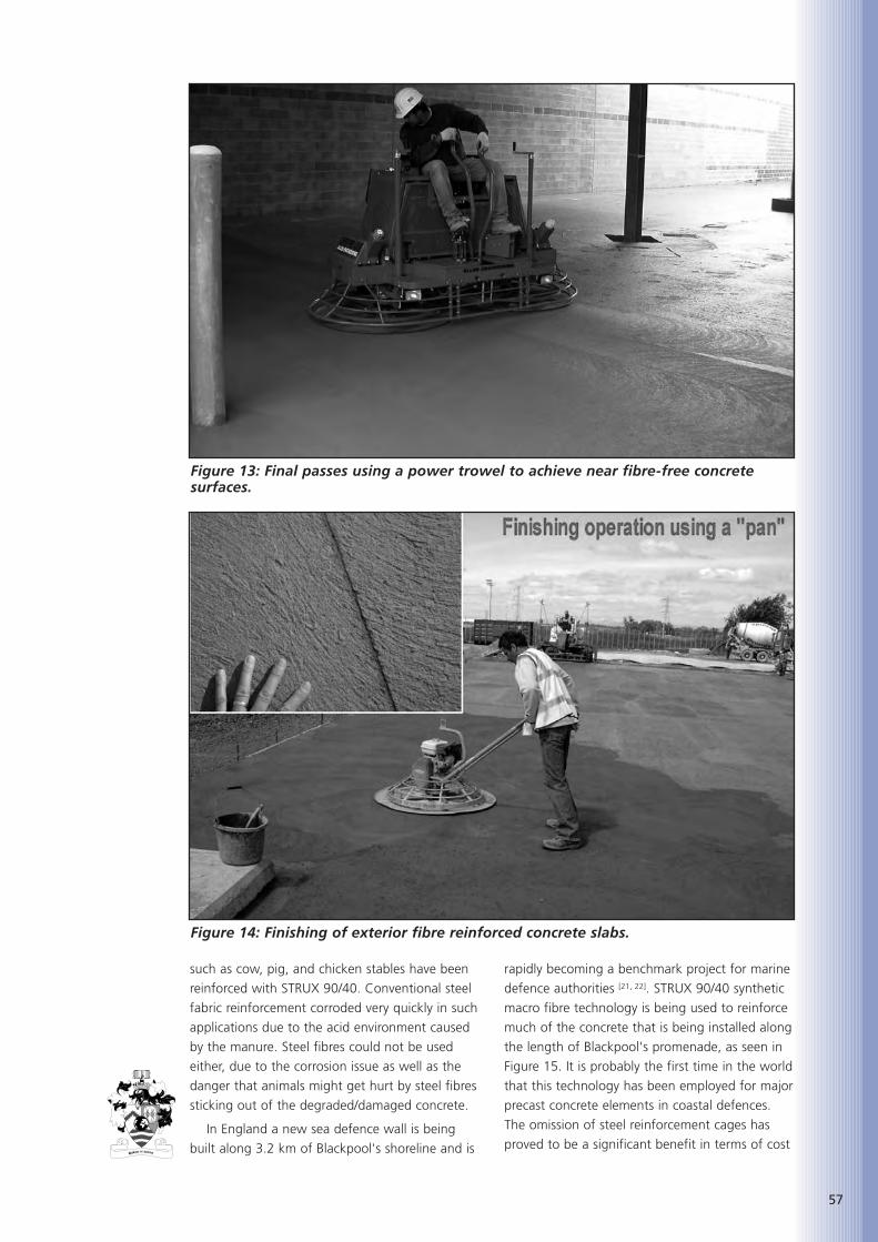
such as cow, pig, and chicken stables have been
reinforced with STRUX 90/40. Conventional steel
fabric reinforcement corroded very quickly in such
applications due to the acid environment caused
by the manure. Steel fibres could not be used
either, due to the corrosion issue as well as the
danger that animals might get hurt by steel fibres
sticking out of the degraded/damaged concrete.
In England a new sea defence wall is being
built along 3.2 km of Blackpool's shoreline and is
rapidly becoming a benchmark project for marine
defence authorities [21, 22]. STRUX 90/40 synthetic
macro fibre technology is being used to reinforce
much of the concrete that is being installed along
the length of Blackpool's promenade, as seen in
Figure 15. It is probably the first time in the world
that this technology has been employed for major
precast concrete elements in coastal defences.
The omission of steel reinforcement cages has
proved to be a significant benefit in terms of cost
57
Figure 13: Final passes using a power trowel to achieve near fibre-free concretesurfaces.
Figure 14: Finishing of exterior fibre reinforced concrete slabs.

58
and time. Using STRUX 90/40 also eliminated the
logistical issues of transporting and storing
tonnes of steel fabric on site. Pouring the
concrete into precast moulds off site, without the
problems surrounding the placement of steel
cages, has also speeded up that side of the
operation.
Another application for STRUX 90/40 is to use
it in composite elevated steel deck flooring. In the
USA and the UK, large-scale fire tests of fully
loaded composite steel decking with fibre
reinforced concrete were conducted
demonstrating that STRUX 90/40 can be used as
an alternative to conventional steel fabric
reinforcement in such applications. In the UK,
Richard Lees Steel Decking incorporated STRUX
90/40 in some of their composite steel decking
designs. The benefits for using STRUX fibre
reinforcement instead of steel fabric are obvious:
since no mesh needs to be stored on site, lifted
up several floors and placed onto the deck, the
construction time and labour savings are
significant.
It should be noted at this point that advice
should be sought whether the local building
codes allow the use of fibres before using fibre
reinforced concrete.
CONCLUSIONSA new generation of high performance
synthetic macro fibres are being increasingly used
in the construction market, primarily to replace
steel fabric reinforcement and steel fibre
reinforcement in concrete slabs-on-ground.
Extensive testing and field experience have shown
that STRUX 90/40 can be used in lieu of steel
fabric or steel fibres in most cases. In addition to
the control of plastic shrinkage, drying shrinkage
and thermal cracks, the flexural capacity of slabs-
on-ground is increased by adding STRUX 90/40 to
the concrete allowing either to increase the
allowable loading of the slab or to decrease the
slab thickness while maintaining the same flexural
capacity of the slab. STRUX 90/40 can be easily
added to the concrete, it disperses well in
concrete, and the fibre reinforced concrete can be
placed and finished with conventional methods.
Since STRUX 90/40 does not corrode and does
not provide any safety hazard, this technology is
an innovative solution to problems related to
concrete steel reinforcement in general.
REFERENCES
1. BECKETT, D. and HUMPHREYS, J.,‘Comparative Tests on Plain, FabricReinforced and Steel Fibre ReinforcedConcrete Ground Slabs’, Report No. TP/B/1,Thames Polytechnic School of CivilEngineering, Dartford, 1989
2. BECKETT, D., ‘Comparative Tests on Plain,Fabric Reinforced and Steel Fibre ReinforcedConcrete Ground Slabs’, Concrete, 1990,Vol. 24, No. 3, pp. 43-45
3. BECKETT, D., Van De WOESTYNE, T, andCallens, S., ‘Corner and Edge Loading onGround Floors Reinforced with Steel Fibers’,Concrete, 1999, Vol. 33, No. 3, pp. 22-24
4. BECKETT, D., ‘Concrete Ground Slabs: AnAppraisal of Corner Loading’, Concrete,2000, Vol. 34, No. 8, 3 pp.
5. FALKNER, H. AND TEUTSCH, M.,‘Comparative Investigations of Plain andSteel Fibre Reinforced Industrial GroundSlabs’, Institut Für Baustoffe, Massivbau undBrandschutz, Technical University ofBrunswick, Germany, 1993, No. 102, 70 pp.
Figure 15: STRUX 90/40 reinforced sea defence wall along Blackpool’s shoreline.

6. FALKNER, H., HUANG, Z., AND TEUTSCH,M., ‘Comparative Study of Plain and SteelFibre Reinforced Concrete Ground Slabs’,Concrete International, 1995, Vol. 17, No.1, pp. 45-51
7. NORDSTRÖM, E., ‘Steel fibre Corrosion inCracks, Durability of Sprayed Concrete’,Ph.D thesis, Luleå University of Technology,Sweden, 2000
8. BERNARD, S., ‘Durability of cracked fibrereinforced shotcrete’, Shotcrete – MoreEngineering Developments, Bernard (editor),Taylor and Francis Group, 2004, pp. 59-66
9. GRANJU, J.-L., BALOUCH, S. U., ‘Corrosionof steel fibre reinforced concrete from thecracks’, Cement and Concrete Research,2005, Vol. 35, pp. 572-577
10. American Society for Testing and Materials,ASTM C 1609-06, ‘Standard Test Methodfor Flexural Performance of Fiber-ReinforcedConcrete (Using Beam With Third-PointLoading)’, Vol. 4.02, 2006
11. Japan Society of Civil Engineers, JSCE-SF4,‘Methods of Tests for Flexural Strength andFlexural Toughness of Steel Fiber ReinforcedConcrete’, Concrete Library International,1984, No. 3, Part III-2, pp. 58-61
12. The Concrete Society, ‘Concrete IndustrialGround Floors – A Guide to Design andConstruction’, Technical Report 34, ThirdEdition, UK, 2003
13. Deutscher Beton-Verein E.V. (DBV),‘Merkblatt Stahlfaserbeton’, 2001 (inGerman)
14. Deutsches Institut für Bautechnik (DIBt),“Zulassungsgrundsätze Faserprodukte alsBetonzusatzstoff“, Schriften des DeutschenInstituts für Bautechnik, Reihe B, Heft 18,2004 (in German)
15. ROESLER, J. R., LANGE, D. A., ALTOUBAT, S.A., RIEDER, K.-A., and ULREICH, G.,“Fracture behavior of plain and fiber-reinforced concrete slabs under monotonicloading,” ASCE Journal of Materials in CivilEngineering, 2004, Vol. 16, Sept./Oct., pp.452-460
16. ROESLER, J. R., ALTOUBAT, S. A., LANGE, D.A., RIEDER, K.-A., and ULREICH, G., “Effectof synthetic fibers on structural behavior ofconcrete slabs on ground“, ACI MaterialsJournal, 2006, Vol. 103, No. 1, pp. 3-10
17. ALTOUBAT, S. A., ROESLER, J. R., andRIEDER, K.-A., ‘Flexural capacity of syntheticfiber reinforced concrete slabs on groundbased on beam toughness results’, RilemProceedings PRO 39, Fibre-ReinforcedConcretes, BEFIB 2004, 6th RILEMSymposium on Fibre-Reinforced Concretes(FRC), Vol. 2, pp. 1063-1072
18. The Concrete Society, ‘Concrete IndustrialGround Floors – A Guide to Design andConstruction’, Technical Report 34, ThirdEdition, UK, 2003
19. BERNARD, S., ‘Creep of cracked fibrereinforced shotcrete panels’, Shotcrete –More Engineering Developments, Bernard(editor), Taylor and Francis Group, 2004, pp.47-57
20. MACKAY J., AND TROTTIER, J.-F., ‘Post-crack behavior of steel and synthetic FRCunder flexural loading’, Shotcrete – MoreEngineering Developments, BERNARD(editor), Taylor and Francis Group, 2004, pp.183-192
21. ‘Defender of the Lights, Blackpool’s newseafront’, New Civil Engineer (NCE) NewConcrete Engineering magazine, 2006,Sept., pp. 10-12
22. PERRY, B., ‘Synthetic macro fibres storm tothe front of coastal defence innovation’,Concrete magazine, 2006, Nov., pp. 72-73
59

60

Alan Poole began his career as
a geologist studying at
Nottingham and Oxford
Universities. He became a
lecturer, first at Swansea and
then at London University.
Since 1975 he has also worked as a consultant
specialising in aggregates, concrete and
armourstone and has particular research interests
in alkali-aggregate reaction and deterioration
mechanisms in concrete. He is involved in various
national and international technical committees,
and in working parties producing technical
reports. He is co-author of several technical books
on aggregates, armourstone, concrete and
applied petrography.
ABSTRACTSoon after 1856 when the polarizing
microscope was first developed the polarizing
petrological microscope was being used for the
study of cement mineralogy. Developments of
resins after the Second World War have made the
preparation of thin transparent slices of concrete
and related materials possible so that they are
suitable for examination under a microscope.
Consequently, petrological investigations have
been extended to cements, mortars, renders,
plasters and a wide range of related construction
materials as a matter of routine. These
procedures have been applied to problems of
specification compliance, materials identification
and quality, the quality of workmanship and
investigation of deterioration and failure in
concrete and other materials. A wide range of
petrological techniques from simple tests and
specific staining to more elaborate techniques
such as x-ray diffraction and scanning electron
microscopy are available to assist the
petrographer. Examples illustrating some of the
techniques applied to Portland cement clinkers
and to hardened concrete are presented.
KEYWORDSPetrology, Polarizing microscope, Cement
clinker, Portland cement concrete, Alkali-
aggregate reaction (AAR,ASR), Sulphate attack,
Ettringite, Pulverised fuel ash (PFA), Ground
granulated blastfurnace slag (ggbs),
Water/cement ratio, Petrographic techniques,
Petrographic thin sections.
INTRODUCTIONThe polarizing petrographic microscope,
though it is today a commonplace, economic and
routine method used for the examination of
cements, aggregates, hardened concrete, renders,
mortars and a wide range of related materials, is
a relatively recent addition to the investigative
techniques available to the civil engineer, the
specifier, architect and others involved in using
materials in the construction industry.
As with the development and use of cement
and concrete, the microscope also has a long
history. The magnifying convex lens was known
to the ancients, but the development of the two
lens compound microscope in 1621 attributed to
Cornelius Drebbel in London, perhaps marked the
beginning of microscopical examination of
materials. A landmark in its history was the
publication of ‘Micrographica’ by Robert Hook in
1665. However, it was not until 1856, after the
development of the achromatic lens by Van Deijl
in 1824, that a polarizing microscope was first
described by a mineralogist, S. Highley, in 1856.
The particular value of the polarizing microscope
arises from the property inherent in many
transparent minerals to resolve the plane of
polarized light causing interference colour effects
which are very useful for mineral identification.
THE EXAMINATION OF CEMENTS AND CONCRETE
Initially the polarizing microscope was used for
identification of crystalline chemicals, but by 1880
this type of microscope was in routine use for
mineralogical identification. Early investigators,
though hampered by poor resolution, soon
established the value of the polarizing microscope
for investigating artificial materials such as
cement clinkers and concrete. The first reported
use of the microscope for studying Portland
cement was by Le Chatelier [1] in 1882, a French
chemist interested in metallurgy and cements. He
used reflected light from a cut and polished
surface to identify Alite (tricalcium silicate) as the
principal phase in cement clinker. Later,
61
CONCRETE UNDER A PETROGRAPHIC MICROSCOPE
Alan Poole, BSc, DPhil, CGeol, EurGeol, FGS, MAE
Consultant in Geomaterials, Petrology & Engineering Geology

62
Törnebohm [2] (1897) successfully identified Alite,
Belite (dicalcium silicate), Celite (tetracalcium
alumino ferrite) together with a glassy residual
phase in clinker. More recent improvements in
polishing and etching techniques allowed Tavasci[3] in 1934 to be the first to identify and quantify
the proportions of these phases in polished
sections of clinkers. Figure 1 shows a modern
polished and etched specimen of clinker (the
colours obtained by the HF etching process assist
identification and are indicated on the left hand
side of the figure).
N. C. Johnson [4], as long ago as 1915, realized
the value of the polarizing microscope for the
investigation of concrete and wrote a series of
articles for the journal ‘Concrete and Concrete
Construction’ which was the forerunner of the
modern journal ‘Concrete’ published by the
Concrete Society. The specimen preparation
techniques were limited at that time so he was
only able to examine polished slabs of concrete
which he viewed through the microscope in
reflected light. He was principally concerned with
aggregate type identification, mix proportions
and the compaction of the concrete. Though
limited by the techniques available his papers
demonstrated the value of the microscope for
assessing mix design and concrete quality.
In more recent times improvements in lens
design have improved resolution dramatically, so
that today crystalline materials only a few microns
across can be identified readily. However, the
study of hydrated cements in the matrix of a
concrete remained difficult because of the
problem of preparing a thin transparent section
of concrete or mortar which had to be no thicker
than 30 microns. After the Second World War
various forms of cold-setting epoxy resins were
developed and these were used to impregnate
and so stabilize a thin layer of concrete thus
allowing the friable matrix and aggregate
particles to be firmly held together so that a thin
section of concrete perhaps 25 microns thick
could be manufactured. Large size thin sections
of concrete could be produced such as is shown
in Figure 2 and these enabled the microscope to
be used routinely to provide a wide range of
detailed information about a concrete or mortar
specimen.
Using the petrographic microscope and thin
sections of this type is now a routine method of
obtaining information about mix proportions,
aggregate types, cement type, admixtures if
included, water/cement ratio, hydration state and
concrete quality. It also enables the petrographer
Figure 1: Polished and HF etched Portland cement clinker in reflected light.
Blue: C2S
Brown: C3S
White: Ferrite
Grey: C3A
Figure 2: Large Format Jig and 150x100mm Thin Section.
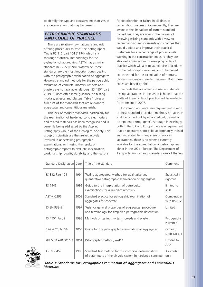
to identify the type and causative mechanisms of
any deterioration that may be present.
PETROGRAPHIC STANDARDS AND CODES OF PRACTICE
There are relatively few national standards
offering procedures to assist the petrographer.
One is BS 812 part 104 (1994) which is a
thorough statistical methodology for the
evaluation of aggregates. ASTM has a similar
standard in C295 (1998). Worldwide, these
standards are the most important ones dealing
with the petrographic examination of aggregates.
However, standard methods for the petrographic
evaluation of concrete, mortars, renders and
plasters are not available, although BS 4551 part
2 (1998) does offer some guidance on testing
mortars, screeds and plasters. Table 1 gives a
fuller list of the standards that are relevant to
aggregates and cementitious materials.
This lack of modern standards, particularly for
the examination of hardened concrete, mortars
and related materials has been recognised and is
currently being addressed by the Applied
Petrography Group of the Geological Society. This
group of scientists are themselves actively
involved in undertaking petrographic
examinations, or in using the results of
petrographic reports to evaluate specification,
workmanship, quality, durability and the reasons
for deterioration or failure in all kinds of
cementitious materials. Consequently, they are
aware of the limitations of current standard
procedures. They are now in the process of
reviewing existing standards with a view to
recommending improvements and changes that
would update and improve their practical
usefulness for a wider range of professionals
working in the construction industry. They are
also well advanced with developing codes of
practice which will aim to standardise procedures
for the petrographic examination of hardened
concrete and for the examination of mortars,
plasters, renders and similar materials. Both these
codes are based on the
methods that are already in use in materials
testing laboratories in the UK. It is hoped that the
drafts of these codes of practice will be available
for comment in 2007.
A common and necessary requirement in most
of these standard procedure methods is that they
shall be carried out by an accredited, trained or
‘competent petrographer’. Although increasingly,
both in the UK and Europe there is a requirement
that an operative should be appropriately trained
and accredited for many areas of work in
laboratories, there is no scheme currently
available for the accreditation of petrographers
either in the UK or Europe. The Department of
Transportation, Ontario, Canada is one of the few
63
Standard Designation Date Title of the standard Comment
BS 812 Part 104 1994 Testing aggregates. Method for qualitative and Statistically
quantitative petrographic examination of aggregates rigorous
BS 7943 1999 Guide to the interpretation of petrological limited to
examinations for alkali-silica reactivity ASR
ASTM C295 2003 Standard practice for petrograhic examination of Comparable
aggregates for concrete with BS 812
BS EN 932-3 1997 Tests for general properties of aggregates, procedure Limited
and terminology for simplified petrographic description
BS 4551 Part 2 1998 Methods of testing mortars, screeds and plaster Petrography
is limited
CSA A 23.2-15A 2003 Guide for the petrographic examination of aggregates Ontario,
Draft No 6.1
RILEM/TC-ARP/01/03 2001 Petrographic method, AAR 1 Limited to
AAR
ASTM C457 1990 Standard test method for microscopical determination Air voids
of parameters of the air void system in hardened concrete only
Table 1: Standards for Petrogaphic Examination of Aggregates and CementiousMaterials.

64
organisations currently exploring procedures for
the accreditation of petrographers involved in the
examination of aggregates and already has a
draft procedure in place.
The Applied Petrography Group are also
concerned that the highest standard of
petrographic reporting is maintained in the UK,
and they are aware that the quality of a report
will depend, in large measure, on the skill and
experience of the petrographer undertaking the
work. However, the cost of setting up and
maintaining a scheme of accreditation for
petrographers is a cause for concern since it is
unlikely to be met by the industry itself.
Nevertheless, the Group is exploring the
possibility of setting up a register of ‘competent
petrographers’ as a particular specialism within a
wider professional register. This work is ongoing
at the present time and it is hoped that some
means of ensuring the quality of the
petrographer and of a petrographic investigation
will be in place by the end of 2007.
PETROGRAPHIC EVALUATION OF CONCRETE AGGREGATES
The engineer, the architect, the contractor and
the client all require that the materials used
during construction meet the specifications and
are ‘fit for purpose’. This holds true for the
concrete used in a structure and for the materials
making up the concrete. Approximately 75% of
the volume of a concrete is composed of
aggregate. Whether the aggregate is coarse or
fine, a crushed stone, gravel, is recycled, or is
artificial, a simple petrographic examination is
undoubtedly the best way of ensuring that it
meets the quality requirements for its end use.
Provided that the sample selected is
representative of the aggregate to be used, the
petrographer will be able to identify the materials
it contains and provide a sensible appraisal of
other likely properties, such as relative density,
compressive strength, water absorption, particle
shape chacteristics and grading, without further
testing, though additional tests may be required
to comply with specification or contractual
requirements. This information can be obtained
from either a representative sample of aggregate,
or a slice of existing concrete (Poole, 2006) [5].
Figure 3 shows a cut and ground slab specimen
of concrete with the aggregates exposed. The
surface has been stained with acidified Alizarin
Red S, which stains the limestone pink (dark in
this photograph) while the dolomite, which
makes up the bulk of the coarse aggregate in this
slab, remains unstained (light). It is also clear that
the coarse aggregate is a crushed rock, is well
graded and that it tends to be ‘flaky’ in shape.
When a loose coarse aggregate sample is
being examined, the petrographer will examine
the particles directly, perhaps using a binocular
microscope or simple lens to examine individual
particles. However, when examining a fine
aggregate sample with a maximum particle size
of 4 or 5 mm, identification of individual grains is
not always easy. In such cases the petrographer
may mix a representative portion of the
aggregate with epoxy resin and cast it as a small
block. When the resin has set, the block may be
cut and lapped to make a transparent thin
section that allows individual grains to be
identified using a petrological microscope. In this
way, the mineralogy of the fine aggregate and
the proportions of the different mineral species
present can be established.
Petrological examination of loose aggregates
or of aggregate in a mortar or concrete is a
particularly effective method for checking
whether the aggregate contains even very small
amounts of contaminants or of deleterious or
unwanted materials such as soft or friable
particles, clay, coal, pyrite or other materials that
can cause problems when incorporated into a
concrete. Consequently it can provide a most
effective quality control method for concrete
aggregates.
PETROGRAPHIC EXAMINATION OF CONCRETE
As has already been noted no satisfactory
standard methods are currently available for the
petrographic examination of concretes, mortars
or related materials. However, this technique can
provide invaluable information over a wide range
Figure 3: Cut Slab of Concrete ShowingDolomite and Limestone CoarseAggregate.
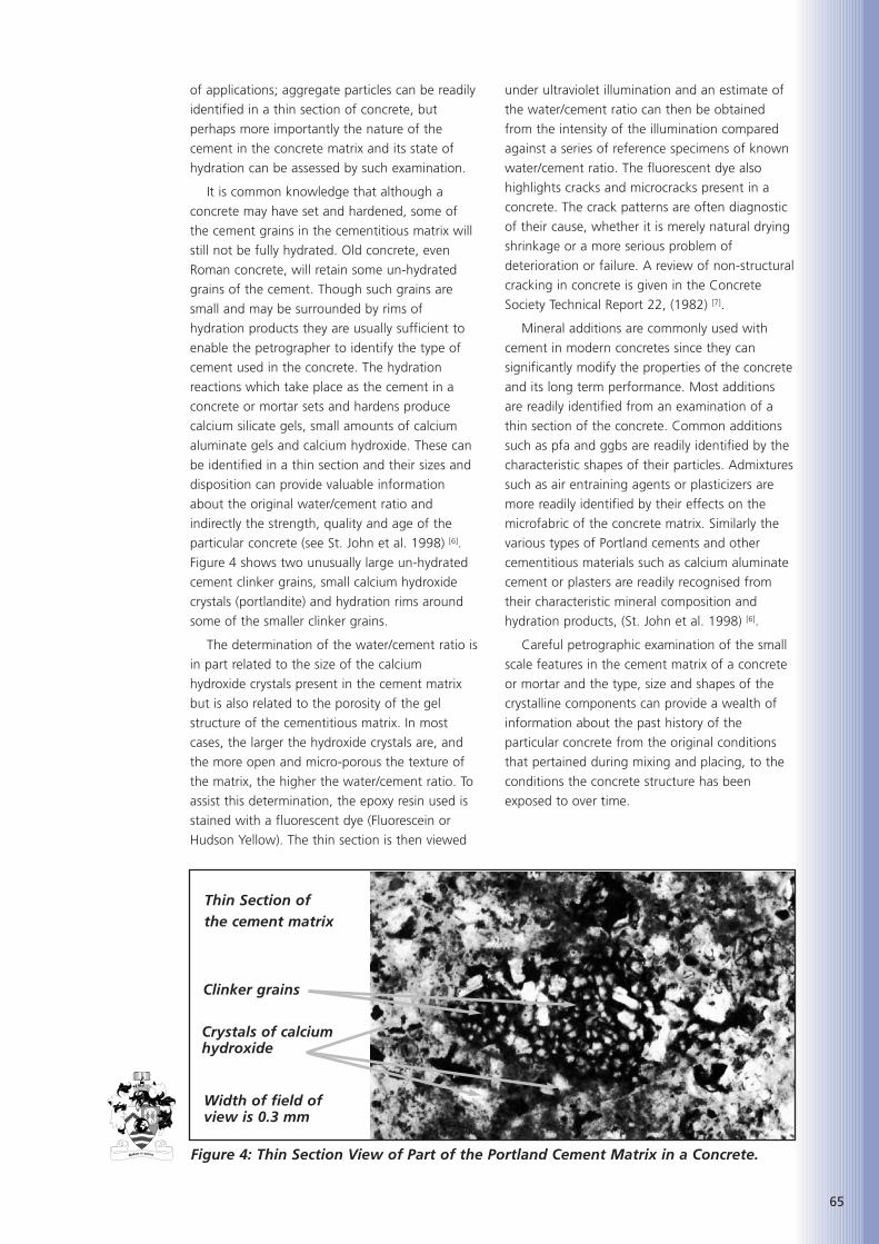
of applications; aggregate particles can be readily
identified in a thin section of concrete, but
perhaps more importantly the nature of the
cement in the concrete matrix and its state of
hydration can be assessed by such examination.
It is common knowledge that although a
concrete may have set and hardened, some of
the cement grains in the cementitious matrix will
still not be fully hydrated. Old concrete, even
Roman concrete, will retain some un-hydrated
grains of the cement. Though such grains are
small and may be surrounded by rims of
hydration products they are usually sufficient to
enable the petrographer to identify the type of
cement used in the concrete. The hydration
reactions which take place as the cement in a
concrete or mortar sets and hardens produce
calcium silicate gels, small amounts of calcium
aluminate gels and calcium hydroxide. These can
be identified in a thin section and their sizes and
disposition can provide valuable information
about the original water/cement ratio and
indirectly the strength, quality and age of the
particular concrete (see St. John et al. 1998) [6].
Figure 4 shows two unusually large un-hydrated
cement clinker grains, small calcium hydroxide
crystals (portlandite) and hydration rims around
some of the smaller clinker grains.
The determination of the water/cement ratio is
in part related to the size of the calcium
hydroxide crystals present in the cement matrix
but is also related to the porosity of the gel
structure of the cementitious matrix. In most
cases, the larger the hydroxide crystals are, and
the more open and micro-porous the texture of
the matrix, the higher the water/cement ratio. To
assist this determination, the epoxy resin used is
stained with a fluorescent dye (Fluorescein or
Hudson Yellow). The thin section is then viewed
under ultraviolet illumination and an estimate of
the water/cement ratio can then be obtained
from the intensity of the illumination compared
against a series of reference specimens of known
water/cement ratio. The fluorescent dye also
highlights cracks and microcracks present in a
concrete. The crack patterns are often diagnostic
of their cause, whether it is merely natural drying
shrinkage or a more serious problem of
deterioration or failure. A review of non-structural
cracking in concrete is given in the Concrete
Society Technical Report 22, (1982) [7].
Mineral additions are commonly used with
cement in modern concretes since they can
significantly modify the properties of the concrete
and its long term performance. Most additions
are readily identified from an examination of a
thin section of the concrete. Common additions
such as pfa and ggbs are readily identified by the
characteristic shapes of their particles. Admixtures
such as air entraining agents or plasticizers are
more readily identified by their effects on the
microfabric of the concrete matrix. Similarly the
various types of Portland cements and other
cementitious materials such as calcium aluminate
cement or plasters are readily recognised from
their characteristic mineral composition and
hydration products, (St. John et al. 1998) [6].
Careful petrographic examination of the small
scale features in the cement matrix of a concrete
or mortar and the type, size and shapes of the
crystalline components can provide a wealth of
information about the past history of the
particular concrete from the original conditions
that pertained during mixing and placing, to the
conditions the concrete structure has been
exposed to over time.
65
Figure 4: Thin Section View of Part of the Portland Cement Matrix in a Concrete.
Width of field ofview is 0.3 mm
Thin Section ofthe cement matrix
Clinker grains
Crystals of calciumhydroxide
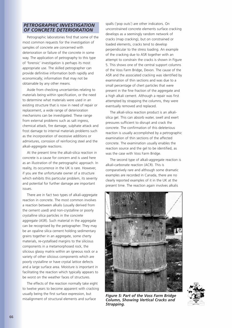
66
PETROGRAPHIC INVESTIGATIONOF CONCRETE DETERIORATION
Petrographic laboratories find that some of the
most common requests for the investigation of
samples of concrete are concerned with
deterioration or failure of the concrete in some
way. The application of petrography to this type
of ‘forensic’ investigation is perhaps its most
appropriate use. The skilled petrographer can
provide definitive information both rapidly and
economically; information that may not be
obtainable by any other means.
Aside from checking uncertainties relating to
materials being within specification, or the need
to determine what materials were used in an
existing structure that is now in need of repair or
replacement, a wide range of deterioration
mechanisms can be investigated. These range
from external problems such as salt ingress,
chemical attack, fire damage, sulphate attack and
frost damage to internal materials problems such
as the incorporation of excessive additions or
admixtures, corrosion of reinforcing steel and the
alkali-aggregate reactions.
At the present time the alkali-silica reaction in
concrete is a cause for concern and is used here
as an illustration of the petrographic approach. In
reality, its occurrence in the UK is rare. However,
if you are the unfortunate owner of a structure
which exhibits this particular problem, its severity
and potential for further damage are important
issues.
There are in fact two types of alkali-aggregate
reaction in concrete. The most common involves
a reaction between alkalis (usually derived from
the cement used) and non-crystalline or poorly
crystalline silica particles in the concrete
aggregate (ASR). Such material in the aggregate
can be recognised by the petographer. They may
be an opaline silica cement holding sedimentary
grains together in an aggregate, some cherty
materials, re-cystallised margins to the silicious
components in a metamorphosed rock, the
silicious glassy matrix within an igneous rock or a
variety of other silicious components which are
poorly crystalline or have crystal lattice defects
and a large surface area. Moisture is important in
facilitating the reaction which typically appears to
be worst on the weather faces of structures.
The effects of the reaction normally take eight
to twelve years to become apparent with cracking
usually being the first surface expression, but
misalignment of structural elements and surface
spalls (‘pop outs’) are other indicators. On
unconstrained concrete elements surface cracking
develops as a seemingly random network of
cracks (map cracking), but on constrained or
loaded elements, cracks tend to develop
perpendicular to the stress loading. An example
of the cracking due to ASR together with an
attempt to constrain the cracks is shown in Figure
5. This shows one of the central support columns
of the Voss Farm Bridge, Devon. The cause of the
ASR and the associated cracking was identified by
examination of thin sections and was due to a
small percentage of chert particles that were
present in the fine fraction of the aggregate and
a high alkali cement. Although a repair was first
attempted by strapping the columns, they were
eventually removed and replaced.
The alkali-silica reaction product is an alkali-
silica gel. This can absorb water, swell and exert
pressures sufficient to disrupt and crack the
concrete. The confirmation of this deleterious
reaction is usually accomplished by a petrographic
examination of thin sections of the affected
concrete. The examination usually enables the
reaction source and the gel to be identified, as
was the case with Voss Farm Bridge.
The second type of alkali-aggregate reaction is
alkali-carbonate reaction (ACR). This is
comparatively rare and although some dramatic
examples are recorded in Canada, there are no
clearly reported examples of it in the UK at the
present time. The reaction again involves alkalis
Figure 5: Part of the Voss Farm BridgeColumn, Showing Vertical Cracks andStrapping.
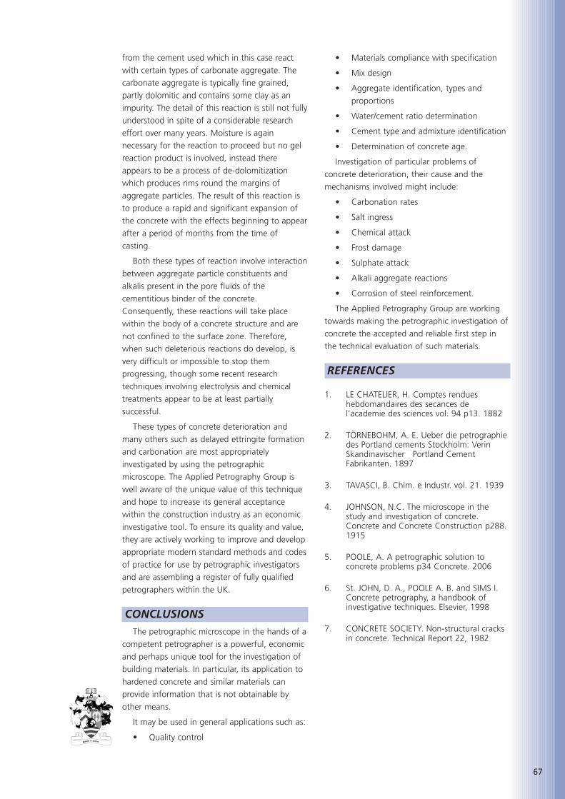
from the cement used which in this case react
with certain types of carbonate aggregate. The
carbonate aggregate is typically fine grained,
partly dolomitic and contains some clay as an
impurity. The detail of this reaction is still not fully
understood in spite of a considerable research
effort over many years. Moisture is again
necessary for the reaction to proceed but no gel
reaction product is involved, instead there
appears to be a process of de-dolomitization
which produces rims round the margins of
aggregate particles. The result of this reaction is
to produce a rapid and significant expansion of
the concrete with the effects beginning to appear
after a period of months from the time of
casting.
Both these types of reaction involve interaction
between aggregate particle constituents and
alkalis present in the pore fluids of the
cementitious binder of the concrete.
Consequently, these reactions will take place
within the body of a concrete structure and are
not confined to the surface zone. Therefore,
when such deleterious reactions do develop, is
very difficult or impossible to stop them
progressing, though some recent research
techniques involving electrolysis and chemical
treatments appear to be at least partially
successful.
These types of concrete deterioration and
many others such as delayed ettringite formation
and carbonation are most appropriately
investigated by using the petrographic
microscope. The Applied Petrography Group is
well aware of the unique value of this technique
and hope to increase its general acceptance
within the construction industry as an economic
investigative tool. To ensure its quality and value,
they are actively working to improve and develop
appropriate modern standard methods and codes
of practice for use by petrographic investigators
and are assembling a register of fully qualified
petrographers within the UK.
CONCLUSIONSThe petrographic microscope in the hands of a
competent petrographer is a powerful, economic
and perhaps unique tool for the investigation of
building materials. In particular, its application to
hardened concrete and similar materials can
provide information that is not obtainable by
other means.
It may be used in general applications such as:
• Quality control
• Materials compliance with specification
• Mix design
• Aggregate identification, types and
proportions
• Water/cement ratio determination
• Cement type and admixture identification
• Determination of concrete age.
Investigation of particular problems of
concrete deterioration, their cause and the
mechanisms involved might include:
• Carbonation rates
• Salt ingress
• Chemical attack
• Frost damage
• Sulphate attack
• Alkali aggregate reactions
• Corrosion of steel reinforcement.
The Applied Petrography Group are working
towards making the petrographic investigation of
concrete the accepted and reliable first step in
the technical evaluation of such materials.
REFERENCES
1. LE CHATELIER, H. Comptes rendueshebdomandaires des secances del’academie des sciences vol. 94 p13. 1882
2. TÖRNEBOHM, A. E. Ueber die petrographiedes Portland cements Stockholm: VerinSkandinavischer Portland CementFabrikanten. 1897
3. TAVASCI, B. Chim. e Industr. vol. 21. 1939
4. JOHNSON, N.C. The microscope in thestudy and investigation of concrete.Concrete and Concrete Construction p288.1915
5. POOLE, A. A petrographic solution toconcrete problems p34 Concrete. 2006
6. St. JOHN, D. A., POOLE A. B. and SIMS I.Concrete petrography, a handbook ofinvestigative techniques. Elsevier, 1998
7. CONCRETE SOCIETY. Non-structural cracksin concrete. Technical Report 22, 1982
67

68

Nick Buenfeld is a civil engineer
and concrete technologist
specialising in the durability of
concrete structures. Since
2000 he has been Professor of
Concrete Structures at Imperial
College London. He established and heads the
Concrete Durability Group, a multi-disciplinary
group of scientists and engineers aiming to
advance understanding of deterioration processes
and so develop more effective methods of design,
assessment and repair of concrete structures. He
has attracted research grants to the value of over
£4m and has authored/co-authored around 150
publications in refereed journals and conference
proceedings. He served for three two-year terms
on the ICT Council and in 2004 presented The
Seventh Sir Frederick Lea Memorial Lecture to the
Institute. He has been a member of many
national and international technical committees
producing guidance documents for industry and
is a Member of the Editorial Board of Magazine
of Concrete Research. He undertakes
consultancy assignments linked to his research
interests and has provided guidance to the
designers or constructors of many major projects
including the Jubilee Line Extension, the new Los
Angeles Cathedral and the Great Man-Made
River Project in Libya.
ABSTRACTImperial College and CIRIA have recently
investigated the state-of-the-art of automated
and intelligent monitoring of concrete structures
and have produced a Roadmap for the future
development of this field for the UK Department
of Trade and Industry (DTI). This paper discusses
the role of automated monitoring in the
management of concrete structures and describes
the main outputs of the DTI project including a
vision of how monitoring technology and its
application to concrete structures will develop in
the future.
KEYWORDSConcrete, Concrete structures, Automated
monitoring, Intelligent monitoring, Sensors, fibre
optics, MEMS, Wireless, Durability, Degradation,
Deterioration, Corrosion, Life prediction.
INTRODUCTIONA large proportion of the infrastructure of the
developed world is built in concrete and is
required to remain in service for at least 50 years.
Major bridges, dams, heritage buildings and
nuclear storage facilities are often expected to
have lives well in excess of 100 years. With
appropriate design, selection of materials and
construction practice it is possible to produce
concrete structures that will be adequately
durable in most exposure environments.
However, concrete structures do deteriorate and
the complex chemistry of cement, the use of steel
reinforcement and the variety of exposure
environments result in a number of, often
interacting, degradation processes. For most
structures deterioration is so slow that no early
intervention is required. However, deterioration
eventually becomes more rapid and repair or
replacement is required. This is costly in terms of
the materials and labour involved, the disruption
to users and other social costs. Unexpected
failures can have particularly severe financial,
environmental and safety implications.
As deterioration progresses, it becomes
increasingly expensive to rectify. Consequently it
is important to identify deterioration early,
determine its structural significance, and to
monitor the structure so that a timely
intervention is possible and so that more serious
problems may be avoided. Traditionally,
monitoring has been based on visual inspection.
However, increasingly sensors are being mounted
on structures and readings taken automatically to
provide real-time condition information. Where
Automated Monitoring of this kind is used to
explicitly provide information on current condition
and to assist in predicting the remaining life of a
component or structure it is referred to as
Intelligent Monitoring.
In 2004 the Department of Trade and Industry
(DTI) commissioned CIRIA and Imperial College to
investigate the state-of-the-art of the intelligent
monitoring of concrete structures and to produce
69
AUTOMATED MONITORING OF THE CONDITION
OF CONCRETE STRUCTURES
Professor Nick Buenfield, PhD, MSc, BSc(Hons), DIC, CEng, MICE, MICT
Imperial College, London
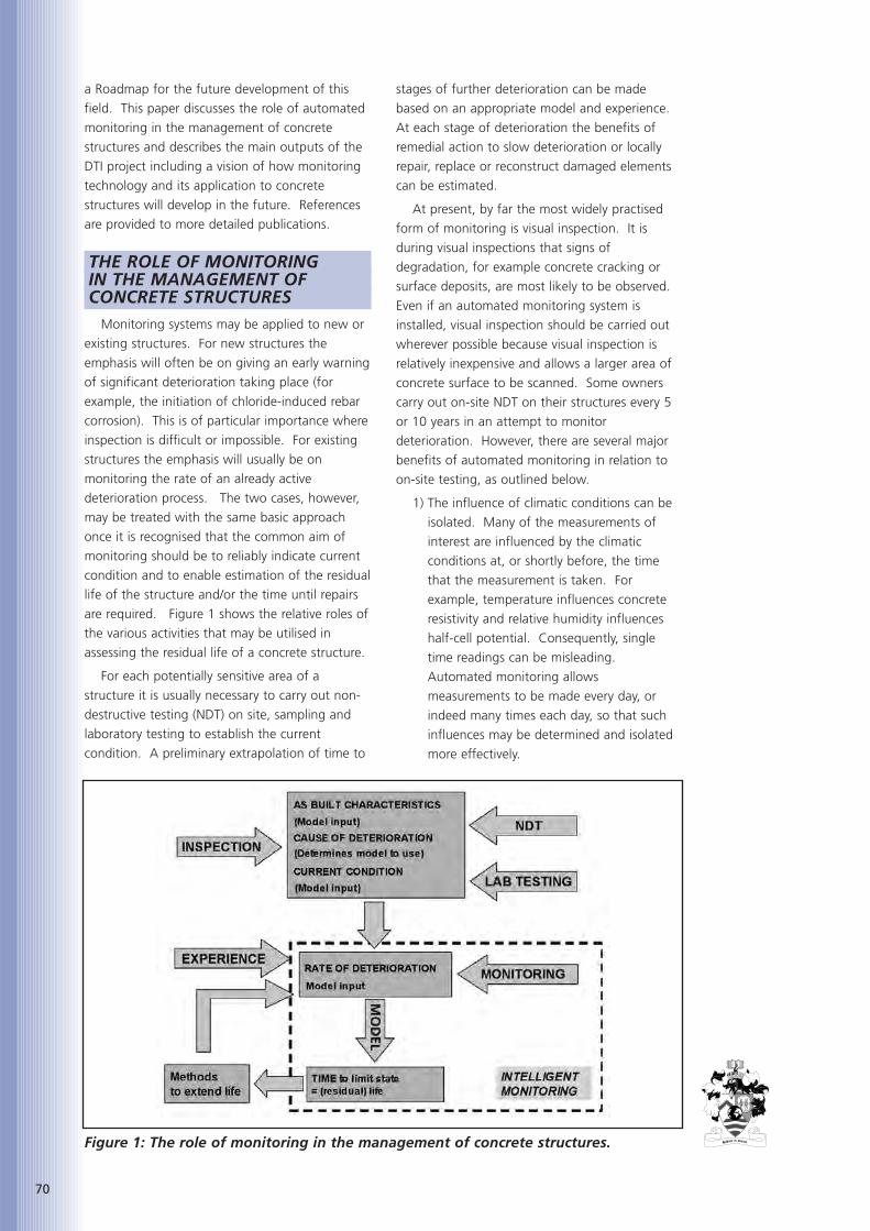
70
a Roadmap for the future development of this
field. This paper discusses the role of automated
monitoring in the management of concrete
structures and describes the main outputs of the
DTI project including a vision of how monitoring
technology and its application to concrete
structures will develop in the future. References
are provided to more detailed publications.
THE ROLE OF MONITORING IN THE MANAGEMENT OF CONCRETE STRUCTURES
Monitoring systems may be applied to new or
existing structures. For new structures the
emphasis will often be on giving an early warning
of significant deterioration taking place (for
example, the initiation of chloride-induced rebar
corrosion). This is of particular importance where
inspection is difficult or impossible. For existing
structures the emphasis will usually be on
monitoring the rate of an already active
deterioration process. The two cases, however,
may be treated with the same basic approach
once it is recognised that the common aim of
monitoring should be to reliably indicate current
condition and to enable estimation of the residual
life of the structure and/or the time until repairs
are required. Figure 1 shows the relative roles of
the various activities that may be utilised in
assessing the residual life of a concrete structure.
For each potentially sensitive area of a
structure it is usually necessary to carry out non-
destructive testing (NDT) on site, sampling and
laboratory testing to establish the current
condition. A preliminary extrapolation of time to
stages of further deterioration can be made
based on an appropriate model and experience.
At each stage of deterioration the benefits of
remedial action to slow deterioration or locally
repair, replace or reconstruct damaged elements
can be estimated.
At present, by far the most widely practised
form of monitoring is visual inspection. It is
during visual inspections that signs of
degradation, for example concrete cracking or
surface deposits, are most likely to be observed.
Even if an automated monitoring system is
installed, visual inspection should be carried out
wherever possible because visual inspection is
relatively inexpensive and allows a larger area of
concrete surface to be scanned. Some owners
carry out on-site NDT on their structures every 5
or 10 years in an attempt to monitor
deterioration. However, there are several major
benefits of automated monitoring in relation to
on-site testing, as outlined below.
1) The influence of climatic conditions can be
isolated. Many of the measurements of
interest are influenced by the climatic
conditions at, or shortly before, the time
that the measurement is taken. For
example, temperature influences concrete
resistivity and relative humidity influences
half-cell potential. Consequently, single
time readings can be misleading.
Automated monitoring allows
measurements to be made every day, or
indeed many times each day, so that such
influences may be determined and isolated
more effectively.
Figure 1: The role of monitoring in the management of concrete structures.
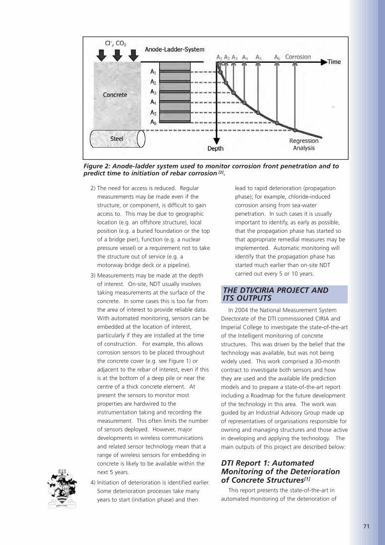
2) The need for access is reduced. Regular
measurements may be made even if the
structure, or component, is difficult to gain
access to. This may be due to geographic
location (e.g. an offshore structure), local
position (e.g. a buried foundation or the top
of a bridge pier), function (e.g. a nuclear
pressure vessel) or a requirement not to take
the structure out of service (e.g. a
motorway bridge deck or a pipeline).
3) Measurements may be made at the depth
of interest. On-site, NDT usually involves
taking measurements at the surface of the
concrete. In some cases this is too far from
the area of interest to provide reliable data.
With automated monitoring, sensors can be
embedded at the location of interest,
particularly if they are installed at the time
of construction. For example, this allows
corrosion sensors to be placed throughout
the concrete cover (e.g. see Figure 1) or
adjacent to the rebar of interest, even if this
is at the bottom of a deep pile or near the
centre of a thick concrete element. At
present the sensors to monitor most
properties are hardwired to the
instrumentation taking and recording the
measurement. This often limits the number
of sensors deployed. However, major
developments in wireless communications
and related sensor technology mean that a
range of wireless sensors for embedding in
concrete is likely to be available within the
next 5 years.
4) Initiation of deterioration is identified earlier.
Some deterioration processes take many
years to start (initiation phase) and then
lead to rapid deterioration (propagation
phase); for example, chloride-induced
corrosion arising from sea-water
penetration. In such cases it is usually
important to identify, as early as possible,
that the propagation phase has started so
that appropriate remedial measures may be
implemented. Automatic monitoring will
identify that the propagation phase has
started much earlier than on-site NDT
carried out every 5 or 10 years.
THE DTI/CIRIA PROJECT AND ITS OUTPUTS
In 2004 the National Measurement System
Directorate of the DTI commissioned CIRIA and
Imperial College to investigate the state-of-the-art
of the Intelligent monitoring of concrete
structures. This was driven by the belief that the
technology was available, but was not being
widely used. This work comprised a 30-month
contract to investigate both sensors and how
they are used and the available life prediction
models and to prepare a state-of-the-art report
including a Roadmap for the future development
of the technology in this area. The work was
guided by an Industrial Advisory Group made up
of representatives of organisations responsible for
owning and managing structures and those active
in developing and applying the technology. The
main outputs of this project are described below:
DTI Report 1: AutomatedMonitoring of the Deteriorationof Concrete Structures[1]
This report presents the state-of-the-art in
automated monitoring of the deterioration of
71
Figure 2: Anode-ladder system used to monitor corrosion front penetration and topredict time to initiation of rebar corrosion [2].

72
concrete structures. The report focuses on what is
currently practical (summarised in Table 1), but
also refers to methods under development.
Considerable detail is provided on the sensors
available to monitor structural change, reinforcing
steel corrosion, concrete moisture state,
temperature and chemistry and exposure
environment. The measurement principle,
advantages (in relation to competing techniques)
and limitations, the equipment used and potential
application areas are presented for each of the
main methods. The Appendices contain a mass
of useful information including datasheets for the
different generic types of sensor and monitoring
equipment (with a list of equipment
manufacturers/suppliers) and over 30 case studies
reporting on experience in applying monitoring
systems to various structures. Figure 2 is a
typical page from one of these case studies.
DTI Report 2: Service LifePrediction of Concrete Structuresbased on Automated Monitoring[2]
This report reviews a large number of models
for predicting the service life of concrete
structures and discusses which are most
appropriate for use with data derived from
automated monitoring. Models are empirical,
analytical or numerical in nature and it is this
characteristic that dictates the quantity and
availability of the required input parameters. An
overview is presented highlighting the main
differences between modelling approaches and
probabilistic techniques are presented and
discussed. The vast majority of service life models
presented in the literature and used by industry
have been developed independently of advances
made in the field of automated monitoring. In
many cases the role of intelligent monitoring is
restricted to providing only one or two of the
input variables and in a significant number of the
models reviewed, intelligent monitoring cannot
take any active role in the assessment process.
DTI Report 3: A Roadmap for theDevelopment of IntelligentMonitoring of ConcreteStructures[3]
A Roadmap is provides an informed view of
the future development of a particular field. It
may be used to identify bottlenecks and prioritise
future research funding. Developing a Roadmap
Table 1: Properties/behaviour that it would be beneficial to monitor automaticallyand what is currently feasible.
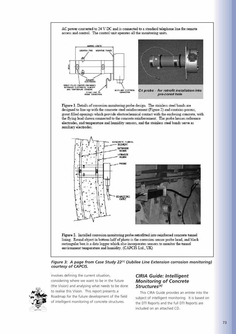
involves defining the current situation,
considering where we want to be in the future
(the Vision) and analysing what needs to be done
to realise this Vision. This report presents a
Roadmap for the future development of the field
of intelligent monitoring of concrete structures.
CIRIA Guide: IntelligentMonitoring of ConcreteStructures[4]
This CIRA Guide provides an entrée into the
subject of intelligent monitoring. It is based on
the DTI Reports and the full DTI Reports are
included on an attached CD.
73
Figure 3: A page from Case Study 22[1] (Jubilee Line Extension corrosion monitoring)courtesy of CAPCIS.

74
A VISION OF THE FUTUREIn developing the Roadmap, a Vision of the
future was required. This had to be a balance
between what is desirable and what is likely,
given that there are many factors involved
beyond the control of those involved with
concrete construction. This involved making
reasonable assumptions, especially about
technology development and incorporating the
requirements and opinions of stakeholders
including owners, consulting engineers and
contractors. This was informed by several
meetings and a workshop, involving the Industrial
Advisory Group, designed to capture these issues.
Ideally the Vision would be described at a specific
time, x years from now. It soon became clear
that the timing is largely dependent on factors
beyond the control of those with a direct interest
in monitoring and/or construction. These factors
include the development of communications
technologies, low power very long-life batteries
and emerging sensor technologies. Consequently
the focus was on identifying likely and desirable
trends, without being unrealistically specific about
their timing. Where it was necessary to be
specific about the Vision date, it was taken as
2020. The paragraphs below summarise key
aspects of this Vision.
In the future, Society is likely to demand that
the condition and risks for all significant
structures are certified, probably once some major
high profile structures have failed due to unseen
deterioration. There will be more pressure on
designers and constructors to produce
demonstrably durable structures and those
responsible for certification will require more
information about the changing condition of
structures. Much of this information will come
from automated monitoring.
Automated monitoring will be considered at
the design stage of most important structures. It
will be applied to structures where the
consequences of reaching a limit state are severe
and where access for visual inspection and testing
is difficult. This will include nuclear waste
repositories, major bridges, city tower blocks,
tunnels, pipelines and offshore platforms. In
many cases monitoring will be focussed on
particular potentially vulnerable details (for
example replaceable bearings) rather than the
whole structure. In some cases structures will be
designed to allow monitoring sensors to be
installed later in the life of the structure, thereby
avoiding sensors degrading or failing before
being useful.
Monitoring will be recognised as a means of
easing the specification of new materials (for
example, new concrete admixtures) with
potentially appropriate properties, but no track
record of real use.
Far more authoritative independent guidance
will be available concerning what is possible and
how to do it. Monitoring the built environment
will be a module on most undergraduate civil
engineering degree courses and specialised MSc
courses are likely to be offered. There will be a
greater number of specialist monitoring
consultants and contractors.
There will be few, if any, aspects of structural
change, rebar corrosion and moisture state that
cannot be measured now that will be measured
by 2020. However, improvements will have been
made to the methods available and their
implementation so that sensors will be more
easily and reliably installed, the measured results
will be more accurate with less drift and sensors
will be more durable. More independently
verified quantitative information will be available
concerning sensor resolution, accuracy, drift and
service life.
Figure 4: MEMS sensors. Left: Wireless tri-axial accelerometer combined with a datalogging transceiver (courtesy of MicroStrain). Right: Micro-sensor for measuringchloride, temperature, moisture and pH in concrete, under development (courtesy ofAdvanced Design Consulting, USA).
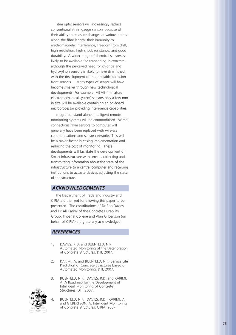
Fibre optic sensors will increasingly replace
conventional strain gauge sensors because of
their ability to measure changes at various points
along the fibre length, their immunity to
electromagnetic interference, freedom from drift,
high resolution, high shock resistance, and good
durability. A wider range of chemical sensors is
likely to be available for embedding in concrete
although the perceived need for chloride and
hydroxyl ion sensors is likely to have diminished
with the development of more reliable corrosion
front sensors. Many types of sensor will have
become smaller through new technological
developments. For example, MEMS (miniature
electromechanical system) sensors only a few mm
in size will be available containing an on-board
microprocessor providing intelligence capabilities.
Integrated, stand-alone, intelligent remote
monitoring systems will be commoditised. Wired
connections from sensors to computer will
generally have been replaced with wireless
communications and sensor networks. This will
be a major factor in easing implementation and
reducing the cost of monitoring. These
developments will facilitate the development of
Smart infrastructure with sensors collecting and
transmitting information about the state of the
infrastructure to a central computer and receiving
instructions to actuate devices adjusting the state
of the structure.
ACKNOWLEDGEMENTSThe Department of Trade and Industry and
CIRIA are thanked for allowing this paper to be
presented. The contributions of Dr Ron Davies
and Dr Ali Karimi of the Concrete Durability
Group, Imperial College and Alan Gilbertson (on
behalf of CIRIA) are gratefully acknowledged.
REFERENCES
1. DAVIES, R.D. and BUENFELD, N.R.Automated Monitoring of the Deteriorationof Concrete Structures, DTI, 2007.
2. KARIMI, A. and BUENFELD, N.R. Service LifePrediction of Concrete Structures based onAutomated Monitoring, DTI, 2007.
3. BUENFELD, N.R., DAVIES, R.D. and KARIMI,A. A Roadmap for the Development ofIntelligent Monitoring of ConcreteStructures, DTI, 2007.
4. BUENFELD, N.R., DAVIES, R.D., KARIMI, A.and GILBERTSON, A. Intelligent Monitoringof Concrete Structures, CIRIA, 2007.
75

76

77
Simon Austin is Professor of
Structural Engineering in the
Department of Civil and
Building Engineering at
Loughborough University, one
of the leading research centres
in the built environment. He is also the founder
director of Adept Management, a specialist
management consultancy. Prior to this he worked
for Scott Wilson Kirkpatrick & Partners and
Tarmac Construction.
He has undertaken industry-focused research
for over 25 years into design processes,
modelling, integrated working and management
techniques, information management, process re-
engineering, value management and structural
materials and their design. The latter includes the
building design process, behaviour and design of
structural elements and innovative sprayed and
cast concretes and mortars.
He is the author of over 200 publications and
holder of over 20 EPSRC funded research grants.
He is a member of various BSi and CEN
standards committees and a consultant member
of two trade associations. His research portfolio
has involved collaboration with many leading
companies and organizations in the construction
industry.
ABSTRACTConstruction has traditionally relied on
specifications and 2D drawings to convey material
properties, performance details and location
information. Advanced 3D solid modelling and
digital fabrication methods are growing in
construction. Iconic building design is driving the
industry towards a new era of the Building
Information Model (BIM) where a building is
modelled entirely using 3D solid CAD tools
containing all the required information for
construction. CNC machinery can utilise this
information to manufacture components enabling
highly bespoke and non-repeating components to
be cost competitive. Rapid Manufacturing
machines also use this information to build
components by selectively adding material rather
than the traditional subtractive or formative
processes. The BIM drives current machines for
the production of models for inspection or to
explore assembly issues. Recent developments are
scaling up these processes so that whole building
components can be built using a mega scale,
additive machine. This paper explores some of the
issues relating to the design of building
components and discusses issues on the
implementation of these process.
KEYWORDSFreeform construction, Rapid manufacturing,
Digital fabrication, Construction design.
INTRODUCTIONIn the manufacturing sector, automation using
industrial robots and machines that use direct
numerical control took hold in the 1960s. The
development of microprocessors delivered
computer numerical control in the 1970s and the
IT revolution in the 1980s brought computer
aided design software. In the 1990s advanced
parametric modelling was introduced and the
industry has enjoyed the development of the
integration of design and analysis tools and
machine control. All these technologies can be
found in construction[1,2,3]. The introduction of
CAD/CAM for the creation of large structural
components for freeform buildings is driving the
development of digital manufacturing
technologies for construction. However, cutting
edge designs for buildings are becoming
increasingly unrealisable using the current state-
of-the-art methods - new processes are required[4,5]. The control of material placement and
reducing the number and quantity of materials
will play a key role. The manufacturing sector is
turning to Rapid Manufacturing (RM) for
solutions, especially for the production of highly
personalised products [6]. The construction
industry is waking up to the potential that
automated additive technologies offer for solving
these problems. Ultimately, it is feasible that such
new processes will drive down the cost of existing
construction, while raising the bar of achievable
APPLYING FUTURE INDUSTRIALISED
PROCESSES TO CONSTRUCTION*
Professor Simon Austin, BSc, PhD, CEng,
Loughborough University
* This paper was co-authored by Richard Buswell, Alistair Gibb, Rupert Soar and Tony Thorpe.

78
construction design solutions. New technologies
are most likely to find niche applications initially
and will eventually filter down to the domestic
sector; exemplified by the Tunnelform system[7].
Over the last ten years there have been
attempts to selectively
bond sand and cement to create freeform
structures from traditional building materials[8].
RM has developed large mould making
processes[9] and the first viable largescale freeform
process for construction, Contour Crafting (CC),
has been demonstrated in the laboratory at the
University of Southern California[10]. Khoshnevis is
pushing for the commercialisation of this process
in the USA. It is capable of producing full scale,
freeform wall structures that would replace the
structural concrete block wall similar to that
found in UK house construction.
Contour Crafting, however, cannot take full
advantage of the extended functionality that can
be embedded within the wall structure if the
principles demonstrated by existing RM processes
are applied. Precise control of very small volumes
of build materials would allow the wall to be
constructed, ground up, with all the internal
pipework, conduits and channels in place,
removing structurally redundant material. The
implications of such an approach would lead to:
clever design solutions using geometric freedom;
a smaller number of build materials and a
reduction in the material resource required for the
construction process; simplify on-site operations
with a reduction in complex trade coordination;
force the resolution of interface issues, hence
reducing part count. Design would be complete
up front and this would mean that the structure
could be designed to be more easily disassembled
and recycled at the end of its life. In addition, the
acoustic, permeability and thermal characteristics
can be modified by ‘printing’ appropriate,
optimised geometry[11].
A concept domestic wall structure, designed
using Freeform Construction principles is depicted
in Figure 1.
New UK research at Loughborough University
is developing a process capable of delivering the
‘Wonderwall’ concept at full scale. This paper
gives details on additive processes and a
discussion of the differences between traditional
and Freeform Construction is given as
background information. The issues surrounding
design practice, design tools, and data and
information protocols are highlighted.
ADDITIVE TECHNOLOGIESThere are various names used to describe
essentially the same type of fabrication
technology; Additive Manufacturing, Rapid
Manufacturing, Rapid Prototyping and Solid
Freeform Fabrication. This method of making
physical components is delivered by many types
of processes; Thermojet, Selective Laser Sintering
(SLS), Stereolithography (SLA), 3D printing (3DP),
Fuse Deposition Modelling (FDM), are a few[12].
Typically each of the processes can use a range of
materials and all have advantages and
disadvantages, suiting them to particular tasks.
They all work ‘print’ 3D structures typically up to
500mm in the x, y and z directions. A design is
usually created using 3D CAD solid modelling. A
model is first tessellated in much the same way as
a Finite Element Analysis mesh is generated then
sliced into layers according the specific machine
parameters. Each slice is sent to a machine. The
machine builds the component by sequentially
creating and bonding each layer to its
predecessor to reproduce the 3D artefact.
Applications vary and can be found in the
literature and on the web sties of companies
offering Rapid Manufacturing services. A good
Figure 1: A concept application for Freeform Construction – 'WonderWall'.

79
source of further reading can be found at Castle
Island[13]. Many classification methods exist for
current RM processes. Application descriptions of
common RM processes are offered here for
discussion of the differences of these in a
construction context. Parallels are drawn between
these process, traditional construction methods
and both existing and conceptual Freeform
Construction technologies.
Comparison of additive processFigure 2 depicts the process of slicing the CAD
model and gives diagrams illustrating the
principal features of mentioned processes. Each
works on a layer-by-layer basis. The SLA and SLS
processes employ a laser; the latter cures a liquid
photo-sensitive resin, the former uses the laser to
melt a small area of powdered material that then
sets to form a solid. The surface finish and
fineness of detail is dependent on the material
properties and the width and intensity of the
laser. The laser ‘rasters’ across the build area with
a fine laser. To speed up the build process, both
processes outline the solid/liquid or powder
boundary on each layer with a fine laser beam
profile and then 'fill in' the area with a de-
Figure 2: Diagrams depicting several of the most commonly used Rapid prototypingprocesses.

80
focussed laser or open hatching strategy. As with
any process, control of operating parameters is
crucial for a successful build. SLS requires a
balance of laser intensity, traverse speed
penetration and time required to either melt or
sinter powder particles into a solid. These
parameters are similar with SLA but the phase
change mechanism is different. Even when these
parameters are tightly controlled, issues arise. For
example, the heat generated during the sintering
process leaves solidified components embedded
in a hot but loose powder ‘cake’. If broken open
too soon then thermal distortion will affect
dimensional tolerances. Table 1 compares the
various processes.
The ‘drop-on-demand’ processes of 3DP and
multi-jet deposition epitomise the idea of three
dimensional printing. All employ raster-based
deposition of either phase change building
materials or binder systems onto powders and
use standard inkjet printer technologies (both PZT
and bubble). Fused Deposition Modelling (FDM)
refers to a family of processes which extrude a
range of thermoplastic polymers to build up a
component in much the same way as squeezing a
tube of toothpaste would.
Rapid Manufacturing machines are designed
to build miniature, hand held and desktop sized
items. A site based construction process is
unlikely to use a laser-augmented approach
(SLA/SLS). In addition, the 'vat of material'
approach is unattractive, because of the
impractical issues associated with post-processing
what would be very large components(SLS/3DP).
This leaves processes that deposit material
through a deposition device (Thermojet/FDM). A
key point is that as you increase the build scale,
the volume flow of material will force the design
of a new process; it cannot simply be scaled up.
For build sizes in the order of 1 to 10 mm, the
build material can be deposited by a printer head
and still maintain a reasonable build speed. Using
the printer head to control deposition of a
curable liquid allows incredibly fine feature sizes,
Table 1 summarises the similarities and differences between the mentionedprocesses.
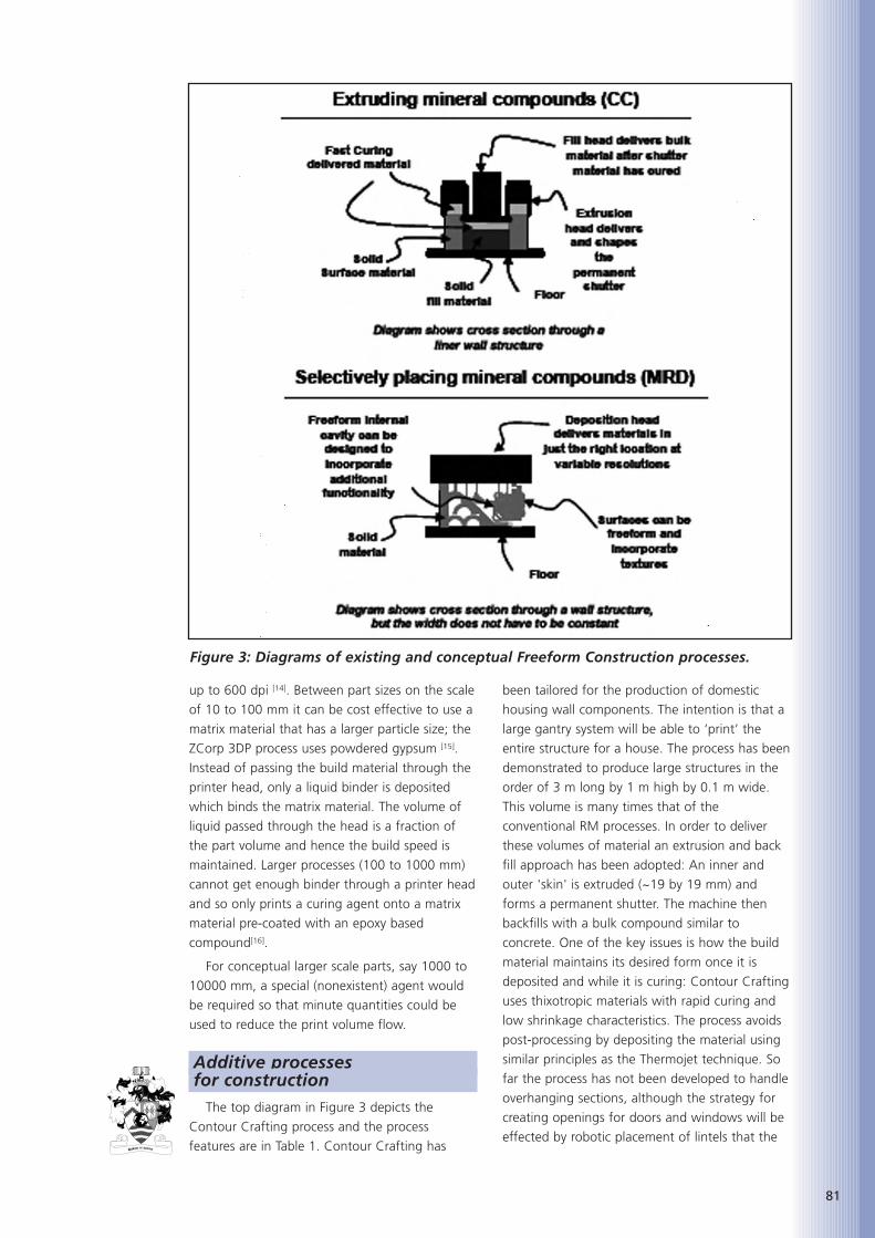
81
up to 600 dpi [14]. Between part sizes on the scale
of 10 to 100 mm it can be cost effective to use a
matrix material that has a larger particle size; the
ZCorp 3DP process uses powdered gypsum [15].
Instead of passing the build material through the
printer head, only a liquid binder is deposited
which binds the matrix material. The volume of
liquid passed through the head is a fraction of
the part volume and hence the build speed is
maintained. Larger processes (100 to 1000 mm)
cannot get enough binder through a printer head
and so only prints a curing agent onto a matrix
material pre-coated with an epoxy based
compound[16].
For conceptual larger scale parts, say 1000 to
10000 mm, a special (nonexistent) agent would
be required so that minute quantities could be
used to reduce the print volume flow.
Additive processes for construction
The top diagram in Figure 3 depicts the
Contour Crafting process and the process
features are in Table 1. Contour Crafting has
been tailored for the production of domestic
housing wall components. The intention is that a
large gantry system will be able to ‘print’ the
entire structure for a house. The process has been
demonstrated to produce large structures in the
order of 3 m long by 1 m high by 0.1 m wide.
This volume is many times that of the
conventional RM processes. In order to deliver
these volumes of material an extrusion and back
fill approach has been adopted: An inner and
outer 'skin' is extruded (~19 by 19 mm) and
forms a permanent shutter. The machine then
backfills with a bulk compound similar to
concrete. One of the key issues is how the build
material maintains its desired form once it is
deposited and while it is curing: Contour Crafting
uses thixotropic materials with rapid curing and
low shrinkage characteristics. The process avoids
post-processing by depositing the material using
similar principles as the Thermojet technique. So
far the process has not been developed to handle
overhanging sections, although the strategy for
creating openings for doors and windows will be
effected by robotic placement of lintels that the
Figure 3: Diagrams of existing and conceptual Freeform Construction processes.
82
deposition head can build off. The shutter
extrusion dimensions limit the feature size that
can be created and the process is given to
producing long, thin walls that can be curved
arbitrarily. The surface finish is trowelled as part
of the process and can achieve very high degrees
of smoothness. The practical wall system that the
Contour Crafted structure would be a part of,
would also need to be clad, insulated, finished
internally, have doors and windows fitted and
mechanical and electrical services, etc. added to
it. Currently the intent is to leave out sections of
the wall as it is ‘printed’ and post-fit services
modules that could be either accessible from the
outside (flush with the surface), or internal, being
built into the wall.
Contour Crafting represents the first
generation of Freeform Construction processes.
The next generation of technologies will be
capable of printing at variable resolutions. A
Multi-Resolution Deposition (MRD) device is
depicted at the bottom of Figure 3. MRD will
build objects at comparable scales and speeds to
Contour Crafting, but will be capable of fine
detailing that gives RM technologies their
strength. The likely specification and process
features will be:
• mineral based compounds (cost)
• selective deposition of material (minimising
post processing)
• feature size down to ~1 mm (control of
surface texture)
• variable deposition resolution (high speed
fill in)
• material shape holding (allow additional
layers while curing)
• high degree of self-supporting features
(minimises post processing)
• inclusion of internal voids and channels
(adding value through function)
• varying material properties through additives
(e.g. for moisture control)
• more freeform surfaces (greater design
freedom for free); and
• more reliable build time and precise
tolerances (machine control).
IMPLICATIONS FOR CONSTRUCTION DESIGN
The MRD Freeform Construction process has
been defined. This section discusses implications
for construction design and issues associated with
design process and information handling. A
conventional UK domestic dwelling wall is cited
here to highlight differences with the concept
wall depicted in Figure 1. This wall might
comprise (typically, from the inside out): 3 mm
coat of finishing plaster to create a hard smooth
finish; 12 mm render to remove imperfections
from the blockwork in preparation for the
finishing plaster; 100 mm load bearing concrete
block wall bedded using a sand/cement mortar;
50 mm cavity filled with an insulation eg, glass
fibre; 100 mm clay brick bedded in mortar, tied
to the internal leaf with steel ties. There are 8
materials listed here and typically 2 trades
required to erect and finish the wall; the
bricklayer and the plasterer. A complete ‘fully
functioning’ wall could include timber and glass
for the doors and windows, employing a
combination of glaziers and joiners; a joiner
would also finish the wall with timber skirting
boards and sills; plastic conduit for electrical
wiring, usually embedded beneath the plaster,
requiring an electrician and labourer; pipework
and panelled heating devices, usually surface
fixed by a plumber. The design now uses nearer
13 materials and 7 trades. In addition, damp-
proofing introduces another material and
openings in the structure require lintels and
usually some sort of temporary former, made in
timber, to guide the brickwork. Scaffold is needed
to elevate the site operatives to access higher
sections of the wall safely. The design becomes a
complicated series of interface resolution issues:
Damp proofing location and draining round
windows; closing cavities; lintel placement;
cutting bricks for openings and defining space;
weatherproofing round windows and doors. The
MRD process would aim to handle many of these
issues with a single operation, utilising reduced
numbers of materials. In the example given, this
process would replace the original 13 materials
with 5; the primary build material, glass, a
framing material, probably an insulating material
and some additive to the primary material for
moisture control. In addition, the thermal
performance could be enhanced[1] and material
resource could be minimised by simply not
printing structurally redundant sections; and there
could be more variation in design because it takes
no more effort or expense to print a curved
section that it does a straight one. The only costs
are; design time, machine setup and run time and
material consumption. It is also likely that self
supporting structures like arches will be employed
to form openings which would reduce the
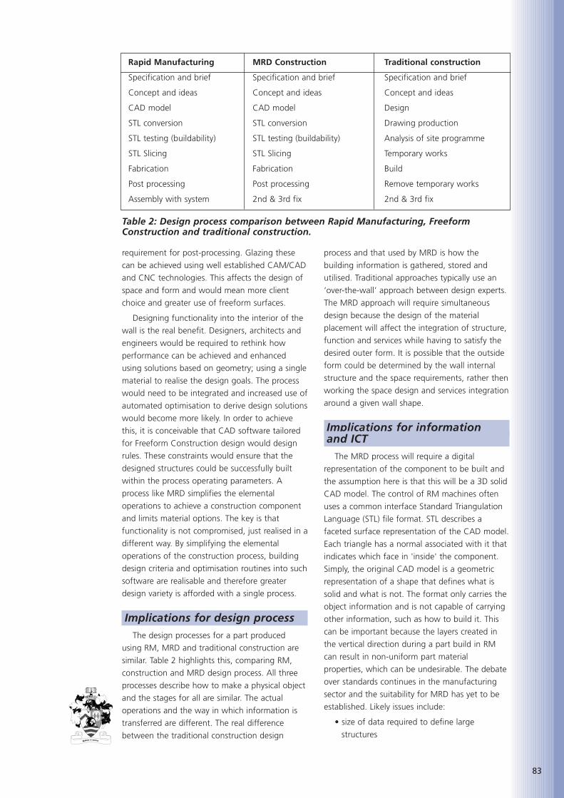
83
requirement for post-processing. Glazing these
can be achieved using well established CAM/CAD
and CNC technologies. This affects the design of
space and form and would mean more client
choice and greater use of freeform surfaces.
Designing functionality into the interior of the
wall is the real benefit. Designers, architects and
engineers would be required to rethink how
performance can be achieved and enhanced
using solutions based on geometry; using a single
material to realise the design goals. The process
would need to be integrated and increased use of
automated optimisation to derive design solutions
would become more likely. In order to achieve
this, it is conceivable that CAD software tailored
for Freeform Construction design would design
rules. These constraints would ensure that the
designed structures could be successfully built
within the process operating parameters. A
process like MRD simplifies the elemental
operations to achieve a construction component
and limits material options. The key is that
functionality is not compromised, just realised in a
different way. By simplifying the elemental
operations of the construction process, building
design criteria and optimisation routines into such
software are realisable and therefore greater
design variety is afforded with a single process.
Implications for design processThe design processes for a part produced
using RM, MRD and traditional construction are
similar. Table 2 highlights this, comparing RM,
construction and MRD design process. All three
processes describe how to make a physical object
and the stages for all are similar. The actual
operations and the way in which information is
transferred are different. The real difference
between the traditional construction design
process and that used by MRD is how the
building information is gathered, stored and
utilised. Traditional approaches typically use an
‘over-the-wall’ approach between design experts.
The MRD approach will require simultaneous
design because the design of the material
placement will affect the integration of structure,
function and services while having to satisfy the
desired outer form. It is possible that the outside
form could be determined by the wall internal
structure and the space requirements, rather then
working the space design and services integration
around a given wall shape.
Implications for informationand ICT
The MRD process will require a digital
representation of the component to be built and
the assumption here is that this will be a 3D solid
CAD model. The control of RM machines often
uses a common interface Standard Triangulation
Language (STL) file format. STL describes a
faceted surface representation of the CAD model.
Each triangle has a normal associated with it that
indicates which face in 'inside' the component.
Simply, the original CAD model is a geometric
representation of a shape that defines what is
solid and what is not. The format only carries the
object information and is not capable of carrying
other information, such as how to build it. This
can be important because the layers created in
the vertical direction during a part build in RM
can result in non-uniform part material
properties, which can be undesirable. The debate
over standards continues in the manufacturing
sector and the suitability for MRD has yet to be
established. Likely issues include:
• size of data required to define large
structures
Rapid Manufacturing MRD Construction Traditional construction
Specification and brief Specification and brief Specification and brief
Concept and ideas Concept and ideas Concept and ideas
CAD model CAD model Design
STL conversion STL conversion Drawing production
STL testing (buildability) STL testing (buildability) Analysis of site programme
STL Slicing STL Slicing Temporary works
Fabrication Fabrication Build
Post processing Post processing Remove temporary works
Assembly with system 2nd & 3rd fix 2nd & 3rd fix
Table 2: Design process comparison between Rapid Manufacturing, FreeformConstruction and traditional construction.

84
• quality of representation of surfaces
• how to handle multiple materials
• the transition from 2D to solid 3D modelling
• the effort in design and analysis
• machine control
• build information
• distribution of build 'knowledge' to machine
• interfacing with existing design tools
• units and tolerances and repeatability.
CONCLUSIONSAutomating construction will deliver benefits
as has been demonstrated in the manufacturing
sector. There are two options, one of which is to
automate human processes. This approach is
flawed for all except very specific tasks because
encoding the complexity of handling materials
coupled with the highly complex decision making
process exhibited by craftsmen is difficult. The
second option is to simplify the elemental
operations controlled by the computer (Pegna,
1997). Many of these simple operations can be
carried out in such a way as to produce a very
complex product. This is the essence of Rapid
Manufacturing and why the process is so suited
to the construction automation issue.
The industry will have to rethink how
components are designed to maximise the
benefits that a process such as MRD can deliver.
The design process will be computer based which
is a goal the industry is already moving towards.
The MRD device is the focus of ongoing research
at Loughborough University.
REFERENCES
1. HOWE, S. 2000, Designing for automatedconstruction. In Automation inConstruction, vol. 9, 259-276.
2. KOLAREVIC, B., 2003, Architecture in theDigital Age: Design and Manufacturing,New York & London: Spon Press - Taylor &Francis Group.
3. SCHODEK, D., BECHTHOLD, M., GRIGGS,K., KAO, K. and STEINBERG, M., 2005,Digital Design and manufacturing:CAD/CAM Applications in Architecture andDesign, First edn, Wiley and Sons, Hoboken,New Jersey.
4. EGAN, J., 1998, Rethinking Construction,Department of the Environment, London.
5. European Construction TechnologyPlatform, 2005, Strategic Research Agendafor the European Construction Sector:Achieving a sustainable and competitiveconstruction sector by 2030, EuropeanConstruction Technology Platform,www.ectp.org.
6. Invisalign, 2006, Invisalign home page[Online]. Available:www.invisalign.com/generalapp/gb/en/[2006, 03/21] .
7. The Concrete Centre 2004, HighPerformance Buildings: Using Tunnel FormConcrete Construction, The ConcreteCentre, Camberley, Surrey, UK.
8. PEGNA, J., 1997, Exploratory investigationof solid freeform construction. InAutomation in Construction, vol. 5, no. 5,427-437.
9. The American Foundry Society, ModernCasting [Online]. Available:http://www.moderncasting.com/archive/ProductInnos/2005/Prod_099_01.asp [2006,03/21] .
10. KHOSHNEVIS, B., 2002, AutomatedConstruction by Contour Crafting: RelatedRobotics and Information Sciences. InAutomation in Construction Special Issue:The best of ISARC 2002, vol. 13, no. 1, 2-9.
11. BUSWELL, R.A., SOAR, R.C., THORPE, A.and GIBB, A.G.F., 2007, FreeformConstruction: Mega-scale Rapidmanufacturing for Construction. InAutomation in Construction, vol. 16, no. 2,222-229.
12. WOHLERS, T. 2004, Rapid Prototyping,Tooling & Manufacturing: State of theIndustry, Wohlers Associates, Colorado,USA.
13. Castle Island, 2006, 7/6/06-last update,Castle Island's Worldwide Guide toRapidPrototyping [Homepage of Castle IslandCo.], [Online]. Available:http://home.att.net/~castleisland/ [2006,21/6/06] .
14. Objet Geometries Ltd. 2006, Objet Homepage. Available: www.2objet.com/ [2006,06/23] .
15. Z Corp 2006, Z Corp Home Page. Available:www.zcorp.com/ [2006, 06/23].
16. Prometal, 2006, Prometal Home page.Available: www.prometal-rt.com [2006,06/23] .

85
Adrian Long is the former
Dean of the Faculty of
Engineering and held the 1849
Chair of Civil Engineering for
30 years. He has over 40 years
of research experience, mainly
on the behaviour of reinforced and prestressed
concrete structures and concrete technology.
ABSTRACTThis paper describes the further development
of a novel flexible masonry concrete arch system,
which requires no centring in the construction
phase or steel reinforcement in the long-term.
The arch is constructed from a ‘flat pack’ system
by use of a polymer reinforcement for supporting
the dead load but behaves as a masonry arch
once in place. The paper outlines the construction
of a prototype arch and load testing of the
backfilled arch system with some comparisons to
the results from ARCHIE. The arch had a load
carrying capacity far in excess of the current
design loads.
KEYWORDS:Concrete, Masonry arch bridges, Polymer
reinforcement.
INTRODUCTIONOn the basis of aesthetics, durability and
strength the arch form of construction is ideal for
bridges; however its Achilles heel is the need for
centring. Thus if an arch system could be
developed which retained all the above attributes
but does not require centring, which currently
makes arch bridges non-competitive, the concept
would be highly attractive for engineers. This
was the main motivation for taking up the
challenge to develop such a system. A further
goal was to overcome persistent problems of
deterioration in existing bridges. For example
many reinforced concrete beam/beam and slab
bridges, whilst initially cost effective in the 1960s
and 70s, have been found to deteriorate relatively
quickly so that many have had to be replaced
well before half their expected design life. In
addition, this latter form of construction often
fails to meet European Standards for load
carrying capacity [1,2], whereas much older arch
bridges have proven to be very satisfactory both
from the viewpoint of strength and durability.
Therefore, this work supports the stated aim of
the UK Highways Agency [3] whereby
consideration shall be given to all means of
reducing or eliminating the use of corrodible
reinforcement indicating the use of plain concrete
structural elements. It also recommends the use
of the arch form of construction where ground
conditions permit.
In Northern Ireland, the total number of
bridges on motorways, trunk and non-trunk
roads is about 6400, of which 64% are masonry
arch structures. The maintenance of these
masonry structures is an annual exercise requiring
significant funding and staff resources and any
saving that can be achieved has significant
financial implications. Annual expenditure on the
maintenance and strengthening of minor
structures, the majority of which are masonry
arches, now amounts to about £5 million in
Northern Ireland alone. Thus an arch bridge
system with low or zero amount of corrodible
reinforcement, which is easy to construct, would
be highly desirable. In response to this challenge
an arch system which does not require centring
has been developed by staff at Queens University
Belfast working alongside Macrete Ireland Ltd
with the support of Invest Northern Ireland, a
Knowledge Transfer Partnership (KTP), the
Institution of Civil Engineers (ICE) and DRD Roads
Service NI. The prototype arch unit has been
manufactured by Macrete, lifted successfully and
monitored during backfill operations [4, 5]. This
paper provides more detailed information on the
development of the arch system and presents the
results of recent load testing of a prototype arch
with concrete backfill.
METHOD OF CONSTRUCTIONThe arch is constructed and transported in the
form of a flat pack using a polymer grid
reinforcement to carry the self weight during
A FLEXIBLE CONCRETE ARCH FOR SUSTAINABLE BRIDGES*
Professor Adrian Long,
PhD, DSc, FEng, FIAE, FACI, FICE, FIStructE, FIEI, FICT
Queen’s University Belfast
* This paper was co-authored by Su Taylor, Abhey Gupta, Jim Kirkpatrick, and Iain Hogg.

lifting but behaves as a masonry arch once in
place.
Basically there are two options for the
construction of the arch unit. The voussoirs can
be precast individually, laid contiguously
horizontally with a layer of polymer grid material
placed on top. An in-situ layer of concrete,
approximately 40 mm thick, is placed on top and
allowed to harden to interconnect the voussoirs.
Alternatively, the same unit can be made in a
single casting operation by using formwork with
wedge formers spaced to simulate the tapered
voussoirs. Both forms of construction are shown
in Fig. 1. The arch unit can be cast in convenient
widths to suit the design requirement, site
restrictions and available lifting capacity. When
lifted, the wedge shaped gaps close, concrete
hinges form in the top layer of concrete and the
unit is supported by tension in the polymer grid.
The arch shaped units are then placed on precast
footings and all self-weight is then transferred
from tension in the polymer to compression in
the arch.
Of the two options above, the first, based on
precast voussoirs, is preferred because with the
second it has been found that it is difficult to:
• Produce accurately machined wedges
which are sufficiently robust to be
anchored to the base form so that
movement does not take place during
casting,
• Remove the hardened concrete unit from
the complex formwork; e.g. uniform
lifting along the complete length is
required or turning upside down with the
possibility of damage when being turned
back after the formwork has been
removed.
MATERIALSControl samples of the polymeric
reinforcement were tested to ascertain the
material properties. The polymer grid is available
in a range of mesh sizes and strengths. The
manufacturer’s data sheet also gave the
longitudinal and transverse tensile strength in
kN/m. Table 1 summarises the results of material
tests carried out at Queen’s University Belfast. The
differences in the measured and specified values
for the tensile strength may be accounted for by
the differences in the test methods. The initial
0.35 m wide arch used a 100/15 Paragrid® but a
stronger grid, 150/15, was used in the 1 m
prototype arch for the lifting and placing of the
arch. The concrete used for casting the voussoirs
was the standard precast mix used by Macrete
Ltd with a 7-day compressive strength of ~40
N/mm2 and a 28-day compressive strength of ~55
N/mm2.
MANUFACTURE OF THE ARCH UNIT
A prototype arch unit of 5 m span, 2 m rise
and 2.5 m internal radius was constructed and
lifted. This arch required twenty-three voussoirs,
which were 1 m wide and 200 mm deep with a
40 mm slab interconnecting in situ screed. The
arch was lifted at approximately the quarter span
points with additional nominal support at the mid
span region. During lifting, the arch drags at
each end and the mid span point tends to sag;
hence the need for the additional support. When
the end cantilevers are fully effective they
produce a hogging moment in the mid span
region which assists in the formation of the arch.
During this operation a critical case occurs when
the arch is fully formed and suspended at the
lifting points. A maximum bending moment
occurs at the lifting points for the cantilever ends
86
Figure 1(a): Construction of arch unitusing pre-cast individual voussoirconcrete blocks.
Figure 1(b): Monolithic construction ofthe arch unit using a special form ofprecast wedges.
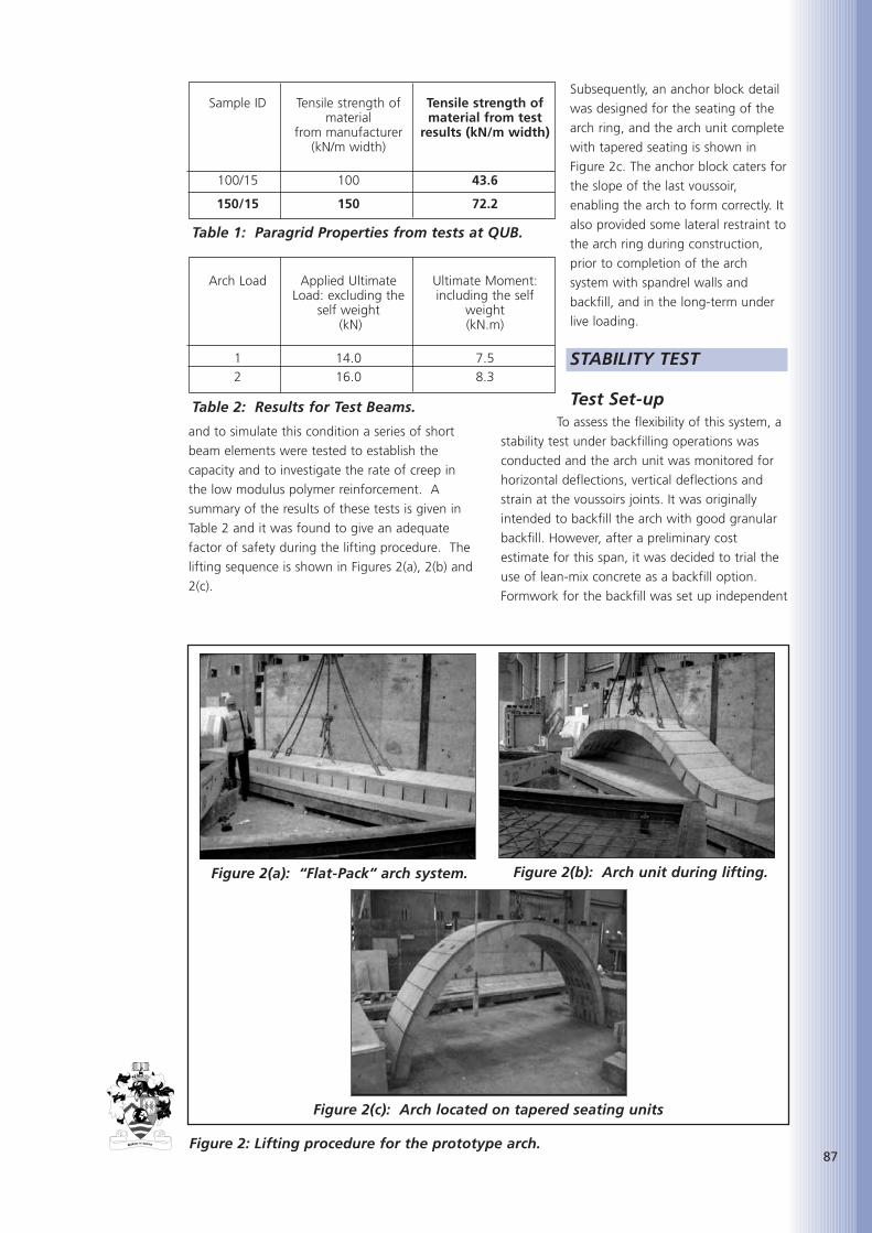
87
and to simulate this condition a series of short
beam elements were tested to establish the
capacity and to investigate the rate of creep in
the low modulus polymer reinforcement. A
summary of the results of these tests is given in
Table 2 and it was found to give an adequate
factor of safety during the lifting procedure. The
lifting sequence is shown in Figures 2(a), 2(b) and
2(c).
Subsequently, an anchor block detail
was designed for the seating of the
arch ring, and the arch unit complete
with tapered seating is shown in
Figure 2c. The anchor block caters for
the slope of the last voussoir,
enabling the arch to form correctly. It
also provided some lateral restraint to
the arch ring during construction,
prior to completion of the arch
system with spandrel walls and
backfill, and in the long-term under
live loading.
STABILITY TEST
Test Set-upTo assess the flexibility of this system, a
stability test under backfilling operations was
conducted and the arch unit was monitored for
horizontal deflections, vertical deflections and
strain at the voussoirs joints. It was originally
intended to backfill the arch with good granular
backfill. However, after a preliminary cost
estimate for this span, it was decided to trial the
use of lean-mix concrete as a backfill option.
Formwork for the backfill was set up independent
Arch Load Applied Ultimate Ultimate Moment: Load: excluding the including the self
self weight weight (kN) (kN.m)
1 14.0 7.52 16.0 8.3
Table 2: Results for Test Beams.
Figure 2: Lifting procedure for the prototype arch.
Figure 2(c): Arch located on tapered seating units
Figure 2(a): “Flat-Pack” arch system. Figure 2(b): Arch unit during lifting.
Sample ID Tensile strength of Tensile strength ofmaterial material from test
from manufacturer results (kN/m width)(kN/m width)
100/15 100 43.6
150/15 150 72.2
Table 1: Paragrid Properties from tests at QUB.

88
of the arch ring to allow free movement during
the placement of the concrete.
Test Procedure and ResultsThe backfilling operation was carried out by
placing approximately 250 mm deep layers of
concrete to each side of the arch and up to 1.5 m
in a horizontal distance from the back face of the
anchor block. The distribution of load to either
side of the arch ring was aimed at minimising the
effects of asymmetric loading. The depth of the
concrete was measured and the transducer and
strain gauge readings were recorded at each
increment of backfill load. The readings showed
a reasonably symmetric response to the
backfilling operation.
The maximum movement in the crown was
0.8 mm upwards in the back face and occurred
at the full height of the concrete backfill. This
was due to the lateral pressure of the wet
concrete creating an inwards movement at the
sides of the arch, which in turn caused the crown
to rise. As the concrete hardened, the lateral
pressure reduced and the deflection response at
the crown reversed in direction; that is, the
upward movement ceased and the crown
deflected very slightly downwards. The results of
the stability tests showed very little movement in
the arch ring and it was concluded that the arch
was stable under the backfilling operations.
LIVE LOAD TESTINGThe 1 m wide prototype flexible concrete arch
system, as shown in Figure 3, was tested in
accordance with the requirements of BS 8110 [6].
A simulated static wheel load was applied at the
mid span and third span of the arch ring. The
single wheel load, for the intended category of
bridge, is 57.5 kN. However, under both loading
conditions, six times the single wheel load, 350
kN, was applied without any signs of distress.
InstrumentationThe instrumentation set-up for the midspan
and third span load tests is shown in Figure 4.
Deflection transducers were used to monitor both
horizontal and vertical deflections and vibrating
wire strain gauges were used to measure crack
openings at the joints between voussoirs.
Testing ProcedureA typical test arrangement is depicted in Figure
4. A circular concentrated load was applied at
the loading position via a 300 mm diameter steel
plate bedded on soft board. An accurately
calibrated 500 kN hydraulic jack was used to
Figure 3: Test set-up for midspan loading.
Figure 4: Instrumentation and test set-up for arch ring and arch with backfill.
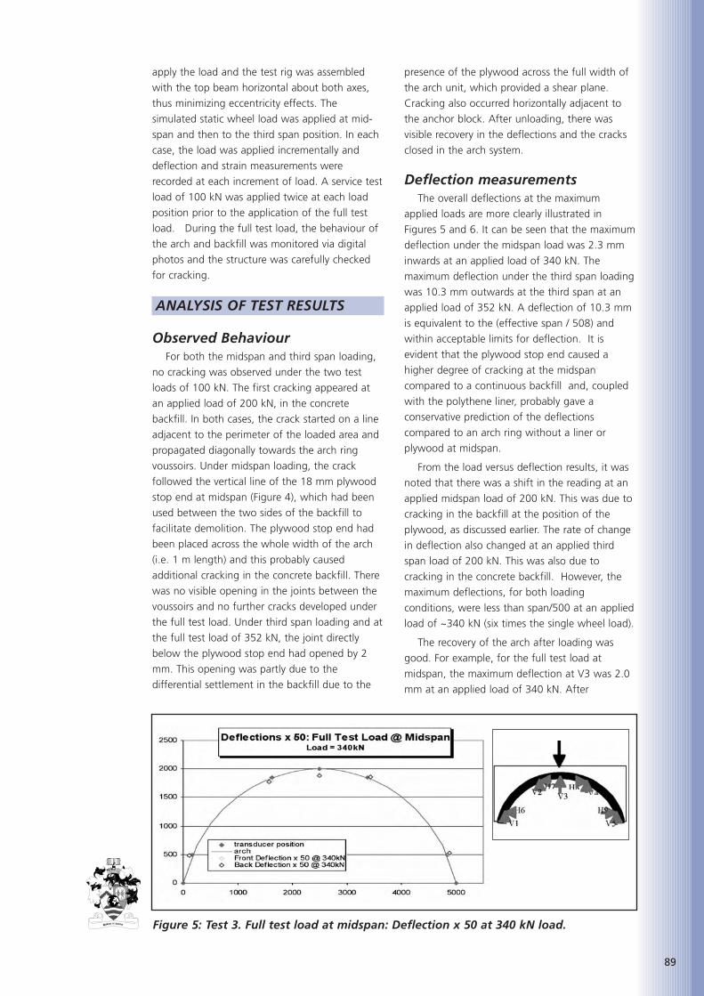
apply the load and the test rig was assembled
with the top beam horizontal about both axes,
thus minimizing eccentricity effects. The
simulated static wheel load was applied at mid-
span and then to the third span position. In each
case, the load was applied incrementally and
deflection and strain measurements were
recorded at each increment of load. A service test
load of 100 kN was applied twice at each load
position prior to the application of the full test
load. During the full test load, the behaviour of
the arch and backfill was monitored via digital
photos and the structure was carefully checked
for cracking.
ANALYSIS OF TEST RESULTS
Observed BehaviourFor both the midspan and third span loading,
no cracking was observed under the two test
loads of 100 kN. The first cracking appeared at
an applied load of 200 kN, in the concrete
backfill. In both cases, the crack started on a line
adjacent to the perimeter of the loaded area and
propagated diagonally towards the arch ring
voussoirs. Under midspan loading, the crack
followed the vertical line of the 18 mm plywood
stop end at midspan (Figure 4), which had been
used between the two sides of the backfill to
facilitate demolition. The plywood stop end had
been placed across the whole width of the arch
(i.e. 1 m length) and this probably caused
additional cracking in the concrete backfill. There
was no visible opening in the joints between the
voussoirs and no further cracks developed under
the full test load. Under third span loading and at
the full test load of 352 kN, the joint directly
below the plywood stop end had opened by 2
mm. This opening was partly due to the
differential settlement in the backfill due to the
presence of the plywood across the full width of
the arch unit, which provided a shear plane.
Cracking also occurred horizontally adjacent to
the anchor block. After unloading, there was
visible recovery in the deflections and the cracks
closed in the arch system.
Deflection measurementsThe overall deflections at the maximum
applied loads are more clearly illustrated in
Figures 5 and 6. It can be seen that the maximum
deflection under the midspan load was 2.3 mm
inwards at an applied load of 340 kN. The
maximum deflection under the third span loading
was 10.3 mm outwards at the third span at an
applied load of 352 kN. A deflection of 10.3 mm
is equivalent to the (effective span / 508) and
within acceptable limits for deflection. It is
evident that the plywood stop end caused a
higher degree of cracking at the midspan
compared to a continuous backfill and, coupled
with the polythene liner, probably gave a
conservative prediction of the deflections
compared to an arch ring without a liner or
plywood at midspan.
From the load versus deflection results, it was
noted that there was a shift in the reading at an
applied midspan load of 200 kN. This was due to
cracking in the backfill at the position of the
plywood, as discussed earlier. The rate of change
in deflection also changed at an applied third
span load of 200 kN. This was also due to
cracking in the concrete backfill. However, the
maximum deflections, for both loading
conditions, were less than span/500 at an applied
load of ~340 kN (six times the single wheel load).
The recovery of the arch after loading was
good. For example, for the full test load at
midspan, the maximum deflection at V3 was 2.0
mm at an applied load of 340 kN. After
Figure 5: Test 3. Full test load at midspan: Deflection x 50 at 340 kN load.
89
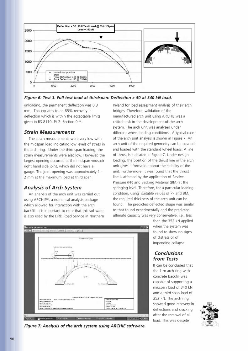
90
unloading, the permanent deflection was 0.3
mm. This equates to an 85% recovery in
deflection which is within the acceptable limits
given in BS 8110: Pt 2: Section 9 [6].
Strain MeasurementsThe strain measurements were very low with
the midspan load indicating low levels of stress in
the arch ring. Under the third span loading, the
strain measurements were also low. However, the
largest opening occurred at the midspan voussoir
right hand side joint, which did not have a
gauge. The joint opening was approximately 1 –
2 mm at the maximum load at third span.
Analysis of Arch SystemAn analysis of the arch unit was carried out
using ARCHIE[7], a numerical analysis package
which allowed for interaction with the arch
backfill. It is important to note that this software
is also used by the DRD Road Service in Northern
Ireland for load assessment analysis of their arch
bridges. Therefore, validation of the
manufactured arch unit using ARCHIE was a
critical task in the development of the arch
system. The arch unit was analysed under
different wheel loading conditions. A typical case
of the arch unit analysis is shown in Figure 7. An
arch unit of the required geometry can be created
and loaded with the standard wheel loads. A line
of thrust is indicated in Figure 7. Under design
loading, the position of the thrust line in the arch
unit gives information about the stability of the
unit. Furthermore, it was found that the thrust
line is affected by the application of Passive
Pressure (PP) and Backing Material (BM) at the
springing level. Therefore, for a particular loading
condition, using suitable values of PP and BM,
the required thickness of the arch unit can be
found. The predicted deflected shape was similar
to that found experimentally and the predicted
ultimate capacity was very conservative, i.e., less
than the 352 kN applied
when the system was
found to show no signs
of distress or of
impending collapse.
Conclusionsfrom TestsIt can be concluded that
the 1 m arch ring with
concrete backfill was
capable of supporting a
midspan load of 340 kN
and a third span load of
352 kN. The arch ring
showed good recovery in
deflections and cracking
after the removal of all
load. This was despite
Figure 6: Test 3. Full test load at thirdspan: Deflection x 50 at 340 kN load.
Figure 7: Analysis of the arch system using ARCHIE software.
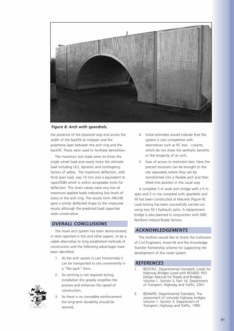
91
the presence of the plywood stop end across the
width of the backfill at midspan and the
polythene layer between the arch ring and the
backfill. These were used to facilitate demolition.
The maximum test loads were six times the
single wheel load and nearly twice the ultimate
load including ULS, dynamic and contingency
factors of safety. The maximum deflection, with
third span load, was 10 mm and is equivalent to
(span/508) which is within acceptable limits for
deflection. The strain values were very low at
maximum applied loads indicating low levels of
stress in the arch ring. The results form ARCHIE
gave a similar deflected shape to the measured
results although the predicted load capacities
were conservative.
OVERALL CONCLUSIONSThe novel arch system has been demonstrated,
in tests reported in this and other papers, to be a
viable alternative to long established methods of
construction and the following advantages have
been identified:
1. As the arch system is cast horizontally it
can be transported to site conveniently in
a “flat pack” form,
2. As centring is not required during
installation this greatly simplifies the
process and enhances the speed of
construction,
3. As there is no corrodible reinforcement
the long-term durability should be
assured,
4. Initial estimates would indicate that the
system is cost competitive with
alternatives such as RC box culverts,
which do not share the aesthetic benefits
or the longevity of an arch,
5. Ease of access to restricted sites. Here the
precast voussoirs can be brought to the
site separately where they can be
transformed into a flexible arch and then
lifted into position in the usual way
A complete 5 m wide arch bridge with a 5 m
span and 2 m rise complete with spandrels and
fill has been constructed at Macrete (Figure 8).
Load testing has been successfully carried out
using two 50 t hydraulic jacks. A replacement
bridge is also planned in conjunction with DRD
Northern Ireland Roads Service.
ACKNOWLEDGEMENTSThe Authors would like to thank the Institution
of Civil Engineers, Invest NI and the Knowledge
Transfer Partnership scheme for supporting the
development of this novel system.
REFERENCES1. BD37/01, Departmental Standard, Loads for
Highway Bridges (used with BS5400: Pt2)Design Manual for Roads and Bridges,Volume 1, Section 3, Part 14, Departmentof Transport, Highway and Traffic, 2001.
2. BD44/95, Departmental Standard, Theassessment of concrete highway bridges,Volume 1, Section 3, Department ofTransport, Highway and Traffic, 1995.
Figure 8: Arch with spandrels.

92
3. UK Highway Agency, BD 57/95 & BA 57/95,Design for Durability Design Manual forRoads and Bridges, Volume 1, Section 3,Department of Transport, Highway andTraffic, 1995.
4. TAYLOR, S.E., GUPTA, A., KIRKPATRICK, J.,LONG, A.E., RANKIN, G.I.B. and HOGG, I.,Development of a novel flexible concretearch system, 11th International Conferenceon Structural Faults and Repairs, Edinburgh,June 2006.
5. GUPTA, A., TAYLOR, S.E., KIRKPATRICK, J.,LONG, A.E. and HOGG, I. A FlexibleConcrete Arch System for Durable BridgesProceeding from IABSE Conference,Budapest, 2006.
6. British Standards Institute, BS 8110: Part 2:Structural use of concrete: Code of practicefor special circumstances Section 9:Appraisal and testing of structures andcomponents for construction, London,1985.
7. ARCHIE-M: Masonry Arch Bridges andViaduct Assessment Software, Version2.0.8, OBVIS Ltd. UK.
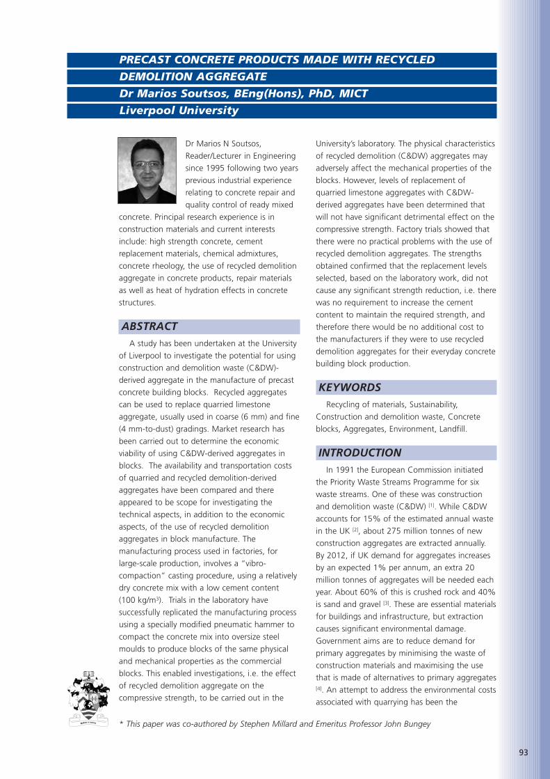
93
Dr Marios N Soutsos,
Reader/Lecturer in Engineering
since 1995 following two years
previous industrial experience
relating to concrete repair and
quality control of ready mixed
concrete. Principal research experience is in
construction materials and current interests
include: high strength concrete, cement
replacement materials, chemical admixtures,
concrete rheology, the use of recycled demolition
aggregate in concrete products, repair materials
as well as heat of hydration effects in concrete
structures.
ABSTRACTA study has been undertaken at the University
of Liverpool to investigate the potential for using
construction and demolition waste (C&DW)-
derived aggregate in the manufacture of precast
concrete building blocks. Recycled aggregates
can be used to replace quarried limestone
aggregate, usually used in coarse (6 mm) and fine
(4 mm-to-dust) gradings. Market research has
been carried out to determine the economic
viability of using C&DW-derived aggregates in
blocks. The availability and transportation costs
of quarried and recycled demolition-derived
aggregates have been compared and there
appeared to be scope for investigating the
technical aspects, in addition to the economic
aspects, of the use of recycled demolition
aggregates in block manufacture. The
manufacturing process used in factories, for
large-scale production, involves a “vibro-
compaction” casting procedure, using a relatively
dry concrete mix with a low cement content
(100 kg/m3). Trials in the laboratory have
successfully replicated the manufacturing process
using a specially modified pneumatic hammer to
compact the concrete mix into oversize steel
moulds to produce blocks of the same physical
and mechanical properties as the commercial
blocks. This enabled investigations, i.e. the effect
of recycled demolition aggregate on the
compressive strength, to be carried out in the
University’s laboratory. The physical characteristics
of recycled demolition (C&DW) aggregates may
adversely affect the mechanical properties of the
blocks. However, levels of replacement of
quarried limestone aggregates with C&DW-
derived aggregates have been determined that
will not have significant detrimental effect on the
compressive strength. Factory trials showed that
there were no practical problems with the use of
recycled demolition aggregates. The strengths
obtained confirmed that the replacement levels
selected, based on the laboratory work, did not
cause any significant strength reduction, i.e. there
was no requirement to increase the cement
content to maintain the required strength, and
therefore there would be no additional cost to
the manufacturers if they were to use recycled
demolition aggregates for their everyday concrete
building block production.
KEYWORDSRecycling of materials, Sustainability,
Construction and demolition waste, Concrete
blocks, Aggregates, Environment, Landfill.
INTRODUCTIONIn 1991 the European Commission initiated
the Priority Waste Streams Programme for six
waste streams. One of these was construction
and demolition waste (C&DW) [1]. While C&DW
accounts for 15% of the estimated annual waste
in the UK [2], about 275 million tonnes of new
construction aggregates are extracted annually.
By 2012, if UK demand for aggregates increases
by an expected 1% per annum, an extra 20
million tonnes of aggregates will be needed each
year. About 60% of this is crushed rock and 40%
is sand and gravel [3]. These are essential materials
for buildings and infrastructure, but extraction
causes significant environmental damage.
Government aims are to reduce demand for
primary aggregates by minimising the waste of
construction materials and maximising the use
that is made of alternatives to primary aggregates[4]. An attempt to address the environmental costs
associated with quarrying has been the
PRECAST CONCRETE PRODUCTS MADE WITH RECYCLED
DEMOLITION AGGREGATE
Dr Marios Soutsos, BEng(Hons), PhD, MICT
Liverpool University
* This paper was co-authored by Stephen Millard and Emeritus Professor John Bungey
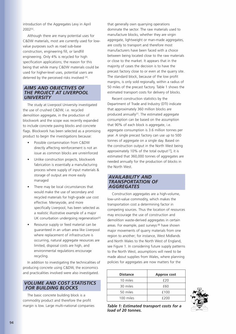
94
introduction of the Aggregates Levy in April
2002[5].
Although there are many potential uses for
C&DW materials, most are currently used for low-
value purposes such as road sub-base
construction, engineering fill, or landfill
engineering. Only 4% is recycled for high
specification applications; the reason for this
being that while many C&DW materials could be
used for higher-level uses, potential users are
deterred by the perceived risks involved [4].
AIMS AND OBJECTIVES OF THE PROJECT AT LIVERPOOL UNIVERSITY
The study at Liverpool University investigated
the use of crushed C&DW, i.e. recycled
demolition aggregate, in the production of
blockwork and the scope was recently expanded
to include concrete paving blocks and concrete
flags. Blockwork has been selected as a promising
product to begin the investigations because:
• Possible contamination from C&DW
directly affecting reinforcement is not an
issue as common blocks are unreinforced
• Unlike construction projects, blockwork
fabrication is essentially a manufacturing
process where supply of input materials &
storage of output are more easily
managed
• There may be local circumstances that
would make the use of secondary and
recycled materials for high-grade use cost
effective. Merseyside, and more
specifically Liverpool, has been selected as
a realistic illustrative example of a major
UK conurbation undergoing regeneration[6]
• Resource supply or feed material can be
guaranteed in an urban area like Liverpool
where replacement of infrastructure is
occurring, natural aggregate resources are
limited, disposal costs are high, and
environmental regulations encourage
recycling.
In addition to investigating the technicalities of
producing concrete using C&DW, the economics
and practicalities involved were also investigated.
VOLUME AND COST STATISTICSFOR BUILDING BLOCKSThe basic concrete building block is a
commodity product and therefore the profit
margin is low. Large multi-national companies
that generally own quarrying operations
dominate the sector. The raw materials used to
manufacture blocks, whether they are virgin
aggregate, lightweight or man-made aggregates,
are costly to transport and therefore most
manufacturers have been faced with a choice
between being located close to the raw materials
or close to the market. It appears that in the
majority of cases the decision is to have the
precast factory close to or even at the quarry site.
The standard block, because of the low profit
margins, is only sold regionally, within a radius of
50 miles of the precast factory. Table 1 shows the
estimated transport costs for delivery of blocks.
Recent construction statistics by the
Department of Trade and Industry (DTI) indicate
that approximately 360 million blocks are
produced annually[7]. The estimated aggregate
consumption can be based on the assumption
that 90% of each block is aggregate, i.e.
aggregate consumption is 3.6 million tonnes per
year. A single precast factory can use up to 500
tonnes of aggregate on a single day. Based on
the construction output in the North West being
approximately 10% of the total output [7], it is
estimated that 360,000 tonnes of aggregates are
needed annually for the production of blocks in
the North West.
AVAILABILITY ANDTRANSPORTATION OF AGGREGATES
Construction aggregates are a high-volume,
low-unit-value commodity, which makes the
transportation cost a determining factor in
competing sources. Thus the location of resources
may encourage the use of construction and
demolition waste-derived aggregates in certain
areas. For example, past surveys [8] have shown
major movements of quarry materials from one
region to another; for instance, West Midlands
and North Wales to the North West of England,
see Figure 1. In considering future supply patterns
to the North West, assumptions will need to be
made about supplies from Wales, where planning
policies for aggregates are now matters for the
Distance Approx cost
10 miles £20
30 miles £60
50 miles £100
100 miles £200
Table 1: Estimated transport costs for aload of 20 tonnes.
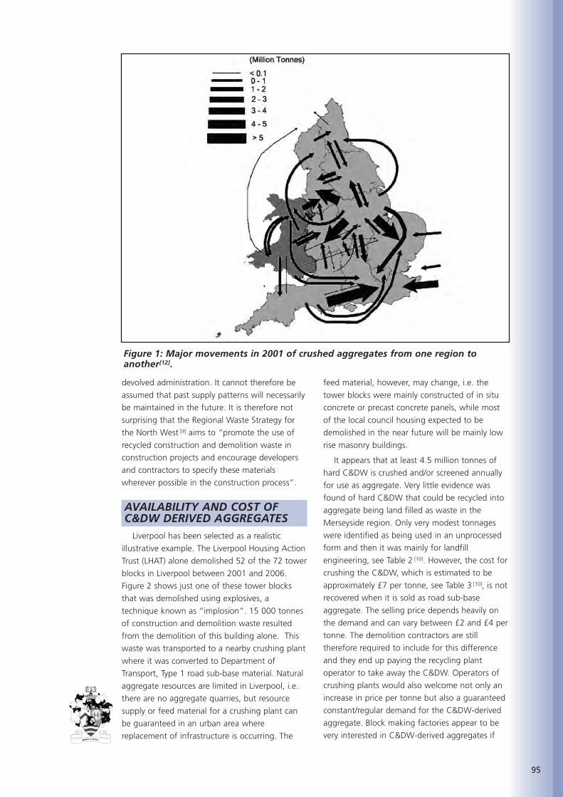
95
devolved administration. It cannot therefore be
assumed that past supply patterns will necessarily
be maintained in the future. It is therefore not
surprising that the Regional Waste Strategy for
the North West [9] aims to “promote the use of
recycled construction and demolition waste in
construction projects and encourage developers
and contractors to specify these materials
wherever possible in the construction process”.
AVAILABILITY AND COST OF C&DW DERIVED AGGREGATES
Liverpool has been selected as a realistic
illustrative example. The Liverpool Housing Action
Trust (LHAT) alone demolished 52 of the 72 tower
blocks in Liverpool between 2001 and 2006.
Figure 2 shows just one of these tower blocks
that was demolished using explosives, a
technique known as “implosion”. 15 000 tonnes
of construction and demolition waste resulted
from the demolition of this building alone. This
waste was transported to a nearby crushing plant
where it was converted to Department of
Transport, Type 1 road sub-base material. Natural
aggregate resources are limited in Liverpool, i.e.
there are no aggregate quarries, but resource
supply or feed material for a crushing plant can
be guaranteed in an urban area where
replacement of infrastructure is occurring. The
feed material, however, may change, i.e. the
tower blocks were mainly constructed of in situ
concrete or precast concrete panels, while most
of the local council housing expected to be
demolished in the near future will be mainly low
rise masonry buildings.
It appears that at least 4.5 million tonnes of
hard C&DW is crushed and/or screened annually
for use as aggregate. Very little evidence was
found of hard C&DW that could be recycled into
aggregate being land filled as waste in the
Merseyside region. Only very modest tonnages
were identified as being used in an unprocessed
form and then it was mainly for landfill
engineering, see Table 2 [10]. However, the cost for
crushing the C&DW, which is estimated to be
approximately £7 per tonne, see Table 3 [10], is not
recovered when it is sold as road sub-base
aggregate. The selling price depends heavily on
the demand and can vary between £2 and £4 per
tonne. The demolition contractors are still
therefore required to include for this difference
and they end up paying the recycling plant
operator to take away the C&DW. Operators of
crushing plants would also welcome not only an
increase in price per tonne but also a guaranteed
constant/regular demand for the C&DW-derived
aggregate. Block making factories appear to be
very interested in C&DW-derived aggregates if
Figure 1: Major movements in 2001 of crushed aggregates from one region toanother[12].

96
the price is lower than that of quarried
aggregate. Approximate aggregate ratios used for
concrete blocks as well as the range of prices per
tonne are shown in Table 4. Normally two sizes of
aggregates are used for concrete block making,
i.e. a 6 mm aggregate and a 4 mm-to-dust
aggregate. A conservative value of £7 per tonne
for 6 mm C&DW-derived aggregates would
satisfy both the operators of crushing plants and
the block making factories. There was therefore
scope for investigating a high-end value market
for C&DW.
PHYSICAL PROPERTIES OF C&DW AGGREGATES
If C&DW-derived aggregates are to be used in
precast concrete products, specific gravity,
absorption, fineness, and angularity are all
important physical properties that need to be
taken into consideration. In the Liverpool study
aggregate gradings have been obtained for
limestone quarried aggregates, supplied by a
block making factory, as well as recycled concrete
and masonry-derived aggregates supplied by local
demolition companies. The concrete C&DW that
was crushed to produce aggregates came from
the foundations of a multi-storey reinforced
concrete building while the masonry C&DW came
from the demolition of low-rise council houses. It
was expected that the detrimental effect of
masonry-derived C&DW aggregates on
compressive strength would be higher than that
of concrete-derived C&DW aggregates. It was
therefore considered prudent to investigate the
effects of concrete- and masonry-derived
aggregates separately, with the possibility of
interpolating to obtain the effects of a mixture of
the two. The percentage of masonry in the
mixture is likely to vary depending on what
contract, whether multi-storey buildings or
masonry houses, the demolition contractor has
secured.
As delivered from the crushing plant, the 4
mm-to-dust recycled masonry was found to be
much finer than natural quarried limestone while
the opposite was found to be true for the
concrete-derived aggregate. In order to obtain a
combined grading similar to that of natural
limestone, the proportion of masonry fines
needed to be reduced from 56% to 43% while
that of concrete fines needed to be increased
from 56% to 61%. However, the initial mixes
indicated that the concrete fines could be
reduced to 45% and still get the same texture on
the blocks as those made with limestone
aggregates. Both the concrete- and the masonry-
derived recycled aggregate had very high water
absorptions: around 10% for the coarse fraction
and up to 18% for the fine fraction.
EXPERIMENTAL WORKThe work described here is divided into three
series of tests; the first series was aimed at
replicating the industrial procedure for making
blocks while the second and third series aimed at
determining the effect of replacing quarried
limestone aggregate with concrete- and masonry-
derived aggregate respectively.
Figure 2: One of fifty-two tower blocks that were demolished in Liverpool between2001 and 2006.

97
Series I – Preliminary TrialsPurpose built moulds were designed and
fabricated in the workshop to enable full height
but half-length block specimens to be made. A
“compaction rig” was designed and fabricated to
produce specimens of the required density, size
and dimensional tolerance. The rig allowed the
vibration/compaction hammer drill to slide down
guide rods to a pre-determined height, see Figure
3. The moulds are oversized in height to allow
the uncompacted material to be placed in them.
The weight of wet material required to produce a
concrete block of approximately 20 kg when dry,
was estimated from previously determined
wet/dry density relationships. The
vibration/compaction hammer drill then
compacted the material to the required height of
215 mm, the height of factory-produced blocks.
Table 2: North West estimates for C&DW Material- Year 2001 [11].
Table 3: Costs for crushing C&DW [14].

Approximately ten tonnes of aggregate were
obtained from a precast concrete factory near
Buxton, Derbyshire. This comprised coarse (6 mm)
and fine (4 mm-to-dust) limestone aggregate.
Specimens were cast, with the proportions of
cement (100 kg/m3), water (30-60 kg/m3), and
coarse and fine aggregate (1250 and 1000 kg/m3
respectively), as given by the factory, to determine
the exact procedure required for replicating the
industrial process. These included:
• Water/cement ratio. The optimum water
cement ratio was found to be the lowest
that allowed a block to be cast and
demoulded immediately after casting
without the block disintegrating
• Curing regime. Laboratory made blocks
were covered in wet hessian and a
polythene sheet for the first 24 hours and
then air cured at ambient laboratory
conditions
• Fibreboard versus mortar capping. The
manufacturers use a predetermined ratio
of 1.06 between the strength of 28-day
mortar-capped blocks and that of 7-day
blocks tested with fibreboard packing on
the ends to simplify and speed up the
testing procedure. The ratio, obtained for
laboratory cast specimens, was very similar
to one used by the manufacturer
• Density. One of the critical parameters in
achieving a target compressive strength
appears to be the density of the concrete
block. A range of acceptable densities, i.e.
1850 to 2000 kg/m3, was provided by a
precast block manufacturer. Blocks made
in the laboratory with a dry density of
2000 kg/m3 achieved strengths above the
target minimum of 7 N/mm2 at 28-days.
Series II – Concrete-derivedaggregates.
After successfully having replicated the
industrial block-making procedure in the
laboratory, the replacement of quarried limestone
with concrete-derived aggregates was
investigated. The mix proportions of
natural limestone aggregate used by
a block making factory, shown in
Table 5 as the “CONTROL”, had to
be converted to volume, replaced by
an equal volume of C&DW recycled
material, and then converted back
into weight. This ensured that the
98
Aggregate Size % of total Approx costaggregates per tonne
used in the mix
4 mm to dust 50-60% £3 – 66 mm 40-30% £8 – 10
Table 4: Prices for quarried aggregates used inconcrete blocks.
Figure 3: Alignment compaction rig.

99
replacement was on a volumetric basis and was
required in order to take into account the
different densities of the recycled aggregates
compared to quarried limestone aggregates.
Blocks made with recycled concrete aggregates
therefore had marginally lower wet densities than
quarried limestone blocks, e.g., 1890 kg/m3 for a
block using 100% replacement of both 6 mm
and 4 mm-to-dust limestone aggregates with
recycled C&DW concrete-derived aggregates
compared to 2125 kg/m3 for a block using only
limestone aggregates.
Each series of mixes started with an initial
cement content of 100 kg/m3. It has been found
from trials that if the concrete mix holds together
after it is squeezed tightly in the hand then the
mix will have sufficient workability to be
compacted into the moulds. A handful of the
concrete mix was taken after mixing for three
minutes. If it did not hold together then
additional water was added. Two or three blocks
were then cast. An increment of additional
cement was then added, the concrete was re-
mixed for another two minutes, and a visual
inspection again determined whether it had
sufficient workability to be compacted into the
moulds. Incremental increase of the cement
content in this manner resulted in blocks with
various cement contents, water-cement ratios,
and therefore compressive strengths. Early age
strengths, i.e. 1-day, were sufficient to allow
moving and stacking of blocks as required in the
manufacturing process. All blocks were tested at
7-days using fibreboard end packing and the
conversion factor of 1.06 was used to convert
this strength to the equivalent 28-day strength.
All the values on the figures are the equivalent
28-day strengths.
Figure 4(a) shows that 100% replacement of
both coarse 6 mm and fine 4 mm-to-dust
quarried limestone aggregate with recycled
C&DW concrete-derived aggregates has a
considerable detrimental effect on the
compressive strength. The cement content would
need to be increased from 100 kg/m3 to
approximately 130 kg/m3 in order for the strength
to be at least 7 MPa.
It was believed that the fines fraction, i.e. 4
mm-to-dust, would be the one that would have
the biggest detrimental effect on the compressive
strength. Studies therefore aimed to replace
either the coarse fraction or the fines fraction
only, but not both, in order to quantify the
relative effects of each fraction. Promising results
were obtained for a 60% replacement of the
coarse fraction with C&DW concrete-derived
aggregate, i.e. there was no detrimental effect on
the compressive strength. However, increasing the
coarse fraction replacement to 100% appears to
have the same detrimental effect as replacing
both the coarse and the fine aggregate fractions
with C&DW concrete-derived aggregates. Figure
4(b) shows that replacing the fine aggregate
fraction only with C&DW concrete-derived
aggregate has more of a detrimental effect on
strength than the coarse aggregate replacement.
Higher than 30% replacement level of fine
aggregate is not recommended. Figure 5 shows
the compressive strength versus the percentage
of replacement of limestone aggregate with
coarse and fine concrete derived aggregates – (All
mixes had 100 kg/m3 of cement). It was
concluded that reasonable replacement levels
would be 60% for the coarse fraction and not
more than 30% for the fine fraction.
Series III – Masonry-derivedaggregates.
The replacement of newly quarried limestone
aggregate with masonry-derived aggregate has
been investigated independently from concrete-
derived aggregates. The lower density of
Table 5: Mix proportions for blocks made with CONCRETE-derived aggregates.
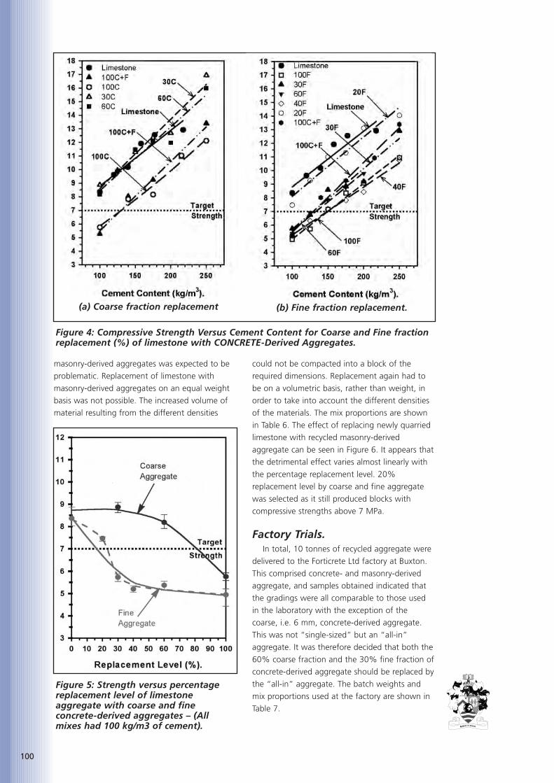
100
masonry-derived aggregates was expected to be
problematic. Replacement of limestone with
masonry-derived aggregates on an equal weight
basis was not possible. The increased volume of
material resulting from the different densities
could not be compacted into a block of the
required dimensions. Replacement again had to
be on a volumetric basis, rather than weight, in
order to take into account the different densities
of the materials. The mix proportions are shown
in Table 6. The effect of replacing newly quarried
limestone with recycled masonry-derived
aggregate can be seen in Figure 6. It appears that
the detrimental effect varies almost linearly with
the percentage replacement level. 20%
replacement level by coarse and fine aggregate
was selected as it still produced blocks with
compressive strengths above 7 MPa.
Factory Trials.In total, 10 tonnes of recycled aggregate were
delivered to the Forticrete Ltd factory at Buxton.
This comprised concrete- and masonry-derived
aggregate, and samples obtained indicated that
the gradings were all comparable to those used
in the laboratory with the exception of the
coarse, i.e. 6 mm, concrete-derived aggregate.
This was not “single-sized” but an “all-in”
aggregate. It was therefore decided that both the
60% coarse fraction and the 30% fine fraction of
concrete-derived aggregate should be replaced by
the “all-in” aggregate. The batch weights and
mix proportions used at the factory are shown in
Table 7.
Figure 4: Compressive Strength Versus Cement Content for Coarse and Fine fractionreplacement (%) of limestone with CONCRETE-Derived Aggregates.
(a) Coarse fraction replacement (b) Fine fraction replacement.
Figure 5: Strength versus percentagereplacement level of limestoneaggregate with coarse and fineconcrete-derived aggregates – (Allmixes had 100 kg/m3 of cement).
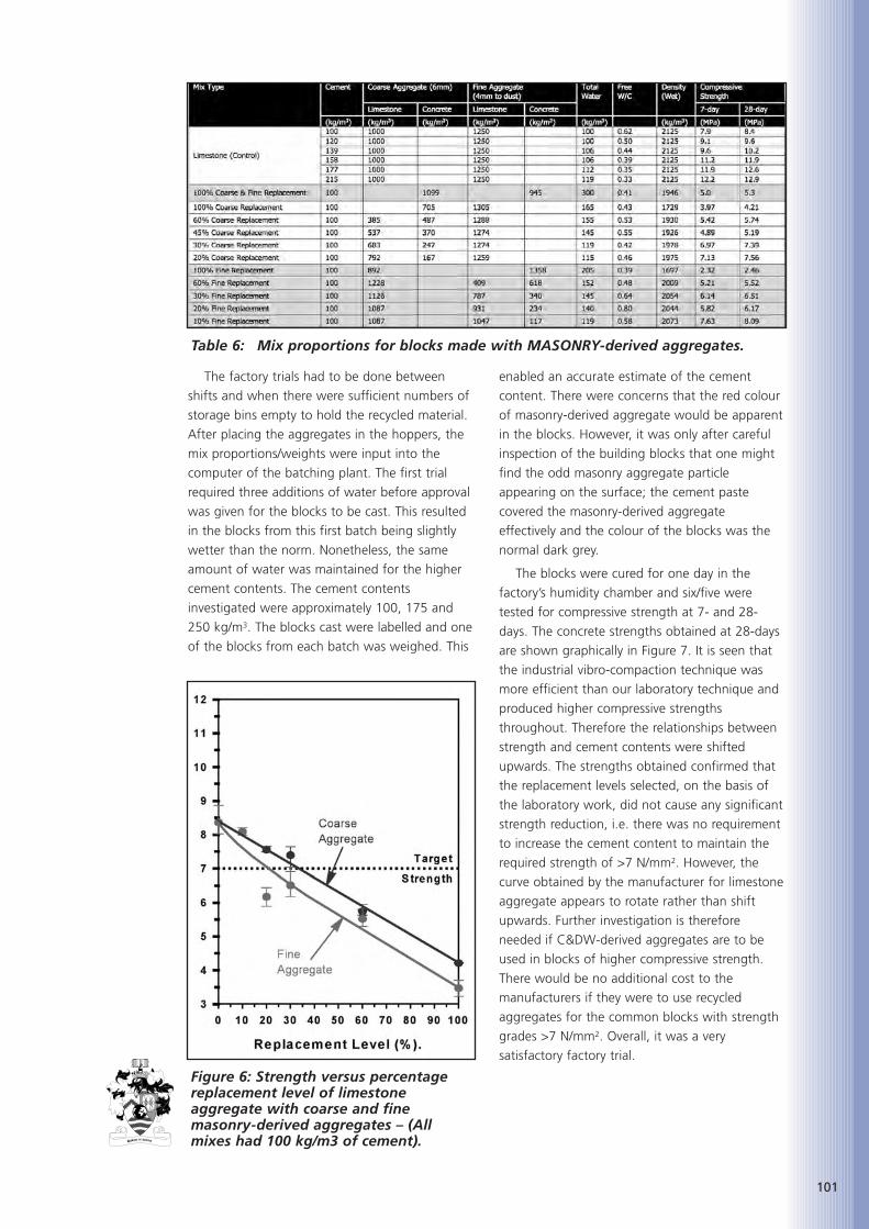
101
The factory trials had to be done between
shifts and when there were sufficient numbers of
storage bins empty to hold the recycled material.
After placing the aggregates in the hoppers, the
mix proportions/weights were input into the
computer of the batching plant. The first trial
required three additions of water before approval
was given for the blocks to be cast. This resulted
in the blocks from this first batch being slightly
wetter than the norm. Nonetheless, the same
amount of water was maintained for the higher
cement contents. The cement contents
investigated were approximately 100, 175 and
250 kg/m3. The blocks cast were labelled and one
of the blocks from each batch was weighed. This
enabled an accurate estimate of the cement
content. There were concerns that the red colour
of masonry-derived aggregate would be apparent
in the blocks. However, it was only after careful
inspection of the building blocks that one might
find the odd masonry aggregate particle
appearing on the surface; the cement paste
covered the masonry-derived aggregate
effectively and the colour of the blocks was the
normal dark grey.
The blocks were cured for one day in the
factory’s humidity chamber and six/five were
tested for compressive strength at 7- and 28-
days. The concrete strengths obtained at 28-days
are shown graphically in Figure 7. It is seen that
the industrial vibro-compaction technique was
more efficient than our laboratory technique and
produced higher compressive strengths
throughout. Therefore the relationships between
strength and cement contents were shifted
upwards. The strengths obtained confirmed that
the replacement levels selected, on the basis of
the laboratory work, did not cause any significant
strength reduction, i.e. there was no requirement
to increase the cement content to maintain the
required strength of >7 N/mm2. However, the
curve obtained by the manufacturer for limestone
aggregate appears to rotate rather than shift
upwards. Further investigation is therefore
needed if C&DW-derived aggregates are to be
used in blocks of higher compressive strength.
There would be no additional cost to the
manufacturers if they were to use recycled
aggregates for the common blocks with strength
grades >7 N/mm2. Overall, it was a very
satisfactory factory trial.
Table 6: Mix proportions for blocks made with MASONRY-derived aggregates.
Figure 6: Strength versus percentagereplacement level of limestoneaggregate with coarse and finemasonry-derived aggregates – (Allmixes had 100 kg/m3 of cement).

102
CONCLUSIONSThe location of aggregate resources may
encourage the use of C&DW-derived aggregates
in certain areas. It is believed that Liverpool,
selected as an illustrative example of a city whose
regeneration calls for demolition and major
reconstruction, can benefit from a high value end
use of C&DW-derived aggregates.
Eleven million tonnes of C&DW material arose
in the North West in 2001. About five million
tonnes were crushed and/or screened for use as
aggregates, mainly for road sub-base. The rest of
the C&DW material was used for landfill
engineering, e.g., landfilling of quarry voids. Very
little evidence was found of hard C&DW that
could be recycled into aggregate being landfilled
as waste. However, the cost of crushing the
C&DW, which is estimated to be approximately
£7 per tonne, is not recovered when it is sold as
road sub-base aggregate. The selling price
depends heavily on the demand and can vary
between £2 and £4 per tonne. The demolition
contractors are still therefore required to include
for this difference and they end up paying the
recycling plant operator to take away the C&DW
Table 7: Batch weights and mix proportions used during the factory trials at Buxton.
Figure 7: 28-day strengths of blocks with limestone replacement (%).
(a) “All-in” CONCRETE-derivedaggregates
(b) 20C/20F MASONRY-derivedaggregates
103
(approximately £2 to £3 per tonne). Operators of
crushing plants would also welcome not only an
increase in price per tonne but also a guaranteed
constant/regular demand for the C&DW derived
aggregate. Block making factories will be
interested in C&DW-derived aggregates if the
price is lower than that of quarried aggregate.
Technical aspects of the replacement ofquarried limestone aggregates with concrete-derived aggregates in the production of blocksneed also be considered. The experimental part ofthis work has shown that the industrial “vibro-compaction” technique used by industry forcasting concrete blocks can be replicated using apneumatic hammer drill. This enabledinvestigations, i.e. the effect of C&DW-derivedaggregate on the compressive strength, to becarried out in a laboratory. Levels of replacementof quarried limestone aggregates with C&DW-derived aggregates have been determined thatwill not have significant detrimental effect on thecompressive strength. The levels for concrete-derived aggregate were determined to be 60%for the coarse fraction, i.e. 6 mm, and 30% forthe fine fraction, i.e. 4 mm-to-dust. The levels formasonry-derived aggregate were determined tobe 20% for the coarse fraction, i.e. 6 mm, and20% for the fine fraction, i.e. 4 mm-to-dust.
Factory trials showed that there were nopractical problems with the use of recycleddemolition aggregates. The strengths obtainedconfirmed that the replacement levels selected,based on the laboratory work, did not cause anysignificant strength reduction, i.e. there was norequirement to increase the cement content tomaintain the required strength, and thereforethere would be no additional cost to themanufacturers if they were to use recycleddemolition aggregates for their everyday concretebuilding block production.
ACKNOWLEDGEMENTSThe authors are grateful to the Veolia
Environmental Trust and the Flintshire Community
Trust Ltd (AD Waste Ltd) for funding this project.
The authors would also like to thank Dr. N. Jones,
Mr. K. Tang and Mr. A. Hatzitheodorou for their
assistance with laboratory work. The authors are
also grateful to the following industrial
collaborators for their in-kind contribution to the
project: Clean Merseyside Centre, Marshalls Ltd,
Forticrete Ltd, Liverpool City Council, Liverpool
Housing Action Trust (LHAT), RMC Readymix Ltd,
WF Doyle & Co. Ltd, and DSM Demolition Ltd.
However, the views expressed here are those of
the authors only and do not necessarily represent
those of the funding bodies or collaborators for
this project.
REFERENCES
1. Aggregates Advisory Service, ‘Constructionand Demolition waste – The EuropeanUnion priority waste streams programme’,Digest No. 011, 1999, p. 4.
2. Environment Agency, ‘Waste Production’,Extract from National SWMI report, WasteStatistics 1998-99, www.environment-agency.gov.uk/commondata/105385/swmiwprind.pdf, 1999, p. 14.
3. Office of the Deputy Prime Minister,‘Planning for the Supply of Aggregates inEngland’,www.odpm.gov.uk/stellent/groups/odpm_planning/documents/pdf/odpm_plan_pdf_605804.pdf October 2000, p.70.
4. HM Treasury, ‘Budget Report 2003: Buildinga Britain of economic strength and socialjustice’, Parliament Street, London SW1P3AG, Chapter 7,
5. www.hm-treasury.gov.uk/budget/bud_bud03/budget_report/bud_bud03_repchap7.cfm, 2003.
6. HM Treasury, ‘Summary of responses to theconsultation on the objectives of thesustainability fund under the aggregateslevy package’.
7. www.hm-treasury.gov.uk/consultations_and_legislation/summary_of_responses_ for_the_sustainability_fund_under_the_aggregates_levy_package_consultation/consult_susfund_index.cfm, Sept. 2000.
9. ‘Regeneration means demolition, MPs told’,New Civil Engineer, 30 Nov. 2000, p. 38.
10. Department of Trade & Industry (DTI),‘Construction Statistics Annual 2003’,www.dti.gov.uk/construction/stats/constat2003.pdf, p. 265, 2003.
11. British Geological Society, ReportCR/03/53N, ‘Collation of the results of the2001 aggregate minerals survey for Englandand Wales’, Keyworth, Nottingham NG125GG, p. 103, 2001.
12. Government Office for the North West,‘Regional Waste Strategy For the NorthWest’, Draft for consultation, http://set.iarna.co.uk/afs/downloads/documents/rws_summary.pdf, p. 43, 21 July 2003.
13. DAVIS, LANGDON and EVEREST, ‘Spon’sCivil Engineering and Highway Works PriceBook 2003’, Taylor & Francis Books Ltd, p.xiv, 2003.

104

105
Jean-Philippe Thierry is an
engineer in material scienceand
has worked for Lafarge since
2001 where he first studied the
fire behaviour of concrete from
conventional to UHPC. He then
worked briefly on fibre orientation before putting
the focus on concrete shrinkage. He is now in
charge of a concrete project and is especially
involved in its deployment.
ABSTRACTThis paper presents an innovative solution for
concrete flooring developed by Lafarge. Joint
spacing is pushed up to 20 m x 20 m without any
reinforcement needed in the concrete.
KEYWORDSConcrete, Flooring, Shrinkage, Drying, Joint
spacing, Reinforcement, Abrasion resistance,
Friction, Subbase.
INTRODUCTIONGround-bearing concrete slabs are often
subject to cracking. It is still important to
distinguish two possible causes:
• Differential settlement in the subbase on
which the slab is laying
• Intrinsic deformation of the concrete due
to drying shrinkage and thermal variations
in buildings.
The former is strictly related to subbase quality,
and especially to compaction homogeneity, which
will not be considered here. The latter is related
to the concrete, for which we propose an
innovative solution.
THE PROPOSED SOLUTIONThe main objective was to develop a solution
that would minimize the cracking risk of slabs.
The specification was to push joint spacing up to
20 m x 20 m, and, if possible, to remove
reinforcement.
Cracking implies that the stresses generated in
the slab are greater than the load capacity of the
concrete. There are two ways of solving this
problem.
Improve concrete propertiesFirst, we have to reduce the drying shrinkage
of the concrete. The best way to do this is to
reduce the quantity of free water remaining in
the concrete after hydration, while controlling the
early-age shrinkage. Typical drying shrinkage
values recorded on instrumented slabs are
between 150 and 250 µm/m.
Then we may also improve the load carrying
capacity of the concrete. Here the solution is
quite straightforward: we have to decrease the
water content. Fortunately, implications in terms
of concrete mix design are close to the ones
related to drying shrinkage. Combining these
two aspects allows us to reach high mechanical
performance: typically a flexural strength of
6MPa.
Ease the deformationsThe average failure strain of concrete in
tension is around 100 µm/m, so even if the
concrete exhibits very small drying shrinkage
deformation completely restraining them would
certainly induce cracking. We also have to take
care with preparatory work on the site and some
recommendations are made to reduce the risk of
cracking.
A ground-bearing slab is not free to move.
The subbase on which it sits is neither smooth
nor flat, so a frictional stress is induced at the
concrete/subbase interface. This stress depends
on the nature of the subbase (gravel, sand, plastic
sheeting, etc.) and on the vertical loading. Many
half-scale tests were carried out to optimise that
interface. A blinded, well-compacted gravel
subbase covered with elastic sheeting gave the
best performance. The stresses induced at the
interface were shown to be 2 to 5 times lower
than on a sand subbase.
SUPPLEMENTARY ADVANTAGESDuring the development phase, we had the
opportunity to place several small slabs. This
allowed us to perform several complementary
characterisations. Firstly, abrasion resistance; our
solution achieved AR Special Class without any
dry-shake on top of the concrete. The
measurements were taken several times by GT
AN INNOVATIVE SOLUTION FOR CONCRETE FLOORING
Dr. Jean-Phillipe Thierry
Lafarge Centre de Recherche

106
Certification, who also checked the pull-off
resistance (2.95 and 1.7 MPa) and the slip
resistance, which conformed to BS 8204-2.
In terms of durability, we measured a low
oxygen permeability (100 x 10m-18 m2), as well as
a low water porosity (9.9%). According to
French recommendations, our solution can be
considered as highly durable.
CONCLUSIONSWith all the work done in the last four years,
we are able to propose a solution that leads to a
low cracking risk and which allows thinner
unreinforced slabs to be designed with less
curling and higher abrasion resistance than
conventional reinforced slabs.

107
Geert De Schutter is full
professor at Ghent University,
Belgium. He is doing research
in the field of concrete
technology, at the Magnel
Laboratory for Concrete
Research, Department of Structural Engineering.
He is laureate of several national and
international awards, among which the important
Vreedenburgh Award in 1998 and the prestigious
international RILEM Robert L’Hermite Medal in
2001. Prof. G. De Schutter is chairman of RILEM
Technical Committee TC 205-DSC on Durability of
SCC. In September 2007, he is organising the
5th International RILEM Symposium on SCC, in
Ghent, Belgium.
ABSTRACTThis paper gives a compilation of the effect of
limestone filler on the hydration, microstructural
development, transport properties and durability
of self-compacting concrete. The effect of
limestone filler (ground calcium carbonate) is
studied in detail, and the importance with regard
to the ‘engineering level’ is outlined.
KEYWORDSself-compacting concrete, limestone filler,
ground calcium carbonate, hydration,
microstructure, transport properties, durability
INTRODUCTIONWith the development of self-compacting
concrete (SCC), a new field of applications has
been realised for ground calcium carbonate. In
order to obtain the key properties of self-
compacting concrete (flow ability, passing ability,
and stability), filler materials are added to the
concrete in large quantities. Besides the normal
cement content (around 300 kg per m3 of
concrete), ground calcium carbonate is added in
quantities of 200 to 300 kg per m3 of concrete.
Within concrete research, ground calcium
carbonate is commonly called limestone filler.
Because of the fundamentally new concept of
SCC, the structure of the material, as a result of
the hydration process, can show some differences
compared to traditionally vibrated concrete. In
order to have a good insight in the effect of
ground calcium carbonate on the properties of
the new cementitious material, a fundamental
study is realised concerning hydration,
microstructure development, and durability. The
effect of SCC is far more important that just
yielding self-compactability. High performance
cementitious materials can be obtained, with
excellent properties not only concerning strength
development, but also related to transport
properties and durability.
In this overview paper, some interesting results
are bundled concerning hydration, microstructure
development, and durability. The effect of
ground calcium carbonate (commonly called
limestone filler) is studied in detail, and the
importance with regard to the ‘engineering level’
is outlined. The results were obtained at the
Magnel Laboratory for Concrete Research.
Several researchers have been involved: Dr. A-M
Poppe, Dr G Ye, Dr K Audenaert, Dr V Boel, and
Dr X. Liu. Their contribution is greatly
acknowledged.
PART I: HYDRATION OFFILLER RICH SELF-COMPACTINGCONCRETE
IntroductionTo realise a concrete that is self-compacting, a
high flowability and a high segregation resistance
have to be combined into one concrete. This is,
as is commonly known, enabled by the use of
superplasticizers and viscosity enhancing agents
combined with high concentrations of fine
particles [1, 2]. As a consequence, these high
concentrations of powder materials (cement and
fillers) can lead to the development of a high
heat of hydration, which might cause problems
during hardening.
Experimental determination ofthe heat of hydration: isothermalhydration tests
To evaluate the heat generation in isothermal
conditions, conduction calorimetry is used. This
test is carried out on small samples of cement
LIMESTONE FILLER BASED SELF-COMPACTING CONCRETE:
FROM MICROSTRUCTURE TO ENGINEERING PROPERTIES
Professor Geert De Schutter, MSc, PhD
Ghent University

108
paste, thus excluding any influences of aggregate
particles. An extensive description of the
conduction method can be found in several
national codes, e.g. the Belgian Standard NBN
B12-213.
In order to be able to make a thorough study
of the heat generation, isothermal hydration tests
are carried out on pure cement as well as on
mixtures of cement and filler. Two different fillers
(a limestone filler originating from Marquise,
France and a quartzite filler originating from Mol,
Belgium) are combined with different portland
cements (CEM I 42.5 R, CEM I 52.5 and CEM I
52.5 HSR LA). In this first stage of the research,
these tests are carried out using no chemical
admixtures such as superplasticizers and viscosity
enhancing agents.
Table 1 gives the powder mixtures as used in
the tests. Four different compositions are
considered, each of which is repeated for the
different cement-filler combinations, and on three
different temperature levels (10°C, 20°C and
35°C). In this table some parameters of the
mixtures are given, such as w/c (water/cement
ratio), w/p (water/powder ratio) and c/p
(cement/powder ratio). In this, the powder
content p is the sum of both cement and filler
materials.
Results of isothermal hydrationtests
Figures 1 to 4 show the heat production rate q
(J/gh) as a function of time t, as experimentally
obtained in the isothermal hydration tests at
20°C (after elimination of the first 'wetting peak',[3, 4]). Similar curves are obtained for the tests at
10°C and 35°C. A more fundamental parameter
than time is the degree of hydration ·, defined as
the cement fraction that has reacted. Due to
difficulties in experimentally determining ·, in this
study the degree of reaction r is used as an
alternative parameter. defined as the fraction of
the heat of hydration that has been released at
any point during testing [3, 4, 5, 6].
In order to study the effect of the filler on the
heat development of the hydrating cement, some
numerical results are summarized in Table 2. In
these tables the mixture label starts with a
Mix 1 Mix 2 Mix 3 Mix 4
cement (g) 7.5 4.5 4.5 2.5
filler (g) - 3 3 5
water (g) 3.75 2.25 3.75 3.75
w/c 0.5 0.5 0.83 1.5
w/p 0.5 0.3 0.5 0.5
c/p 1.0 0.6 0.6 0.33
Table 1 : Composition of the powdermixes used in the isothermal tests.
Figure 1: Heat production rate formixtures with CEM I 42.5 R andlimestone filler at 20°C.
Figure 2 : Heat production rate formixtures with CEM I 52.5 and limestonefiller at 20°C.
Figure 3 : Heat production rate formixtures with CEM I 52.5 HSR LA andlimestone filler at 20°C.
Figure 4 : Heat production rate formixtures with CEM I 42.5 R andquartzite filler at 20°C.

109
number, referring to the composition given in
table 1. Furthermore, the mixture label refers to
the cement type and to the filler type (LF =
limestone filler, QF = quartzite filler). Table 2 gives
the maximum heat production rate qmax (J/gh) for
all different mixes at the three testing
temperatures.
DiscussionFrom the results given in the figures 1 to 4,
and from the corresponding results at different
temperatures, it can be clearly noticed that the
reaction mechanism of the hydrating cement in
some cases might be altered due to the presence
of the filler. This is clearly visible when looking
into the results obtained with CEM I 42.5 R
combined with limestone filler. When limestone
filler is added to the cement, the induction period
is shortened considerably and an extra hydration
peak occurs after about 22 hours for mixes 2 and
3, and after about 15 hours for mix 4. In this
latter case, the second, extra peak has a heat
production rate that is even slightly higher than
the first peak. At 35 °C this effect is even more
pronounced. This can lead to the conclusion that
the more limestone filler is added (and c/p is
decreasing) and the higher the testing
temperature is, the higher the production rate of
the extra peak is.
The alteration of the hydration reaction can
also be noticed for the tests with CEM I 52.5,
though much less pronounced. For CEM I 52.5
HSR LA an alteration of the hydration reaction
with the occurrence of a second hydration peak is
not found. Opposed to the limestone filler, the
quartzite filler does not seem to influence the
induction period, and, apart from a slight waving
of the curve of the hydration rate in some cases,
no extra peak is observed. Adiabatic tests carried
out on a few mixes of self-compacting concrete
confirmed the alterations in the reaction
mechanism found during the isothermal tests.
At this moment the driving force for the
change in hydration mechanism and the
occurrence of the extra hydration peak is not fully
clear. A few different hypotheses can be put
forward. In literature the influence of the filler
material, and in particular limestone filler, on the
hydration of the cement is in most cases
considered to be limited to the rate of the
reactions. Several authors mention that the
setting kinetic is improved, the dormant period is
reduced and the hydration process within the first
hours is accelerated [7, 8, 9, 10]. Kadri et al [11]
suppose that the filler particles promote sites of
heterogeneous nucleation to precipitate more or
less crystallized hydrates, and in this way
accelerate the hydration.
For the occurence of the second hydration
peak a few different hypotheses can be followed.
The noticed effect might be related to the
hydration of the C3A in the cement. Bensted [12]
Mixture qmax at 10°C qmax at 20°C qmax at 35°C
1/ 42.5R – LF 4.03 8.01 17.15
2/ 42.5R – LF 4.81 9.54 19.40
3/ 42.5R – LF 5.07 9.14 21.90
4/ 42.5R – LF 5.40 10.48 27.87
1/ 52.5 – LF 7.20 14.32 30.06
2/ 52.5 – LF 8.57 16.42 33.54
3/ 52.5 – LF 8.26 15.52 34.58
4/ 52.5 – LF 8.53 17.49 35.02
1/ 52.5HSR LA – LF 6.42 12.14 23.44
2/ 52.5HSR LA – LF 7.37 13.62 27.44
3/ 52.5HSR LA – LF 7.05 12.93 26.04
4/ 52.5HSR LA – LF 7.07 14.54 23.58
1/ 42.5R – QF 4.03 8.01 17.15
2/ 42.5R – QF 4.76 9.35 14.88
3/ 42.5R – QF 4.99 8.66 15.71
4/ 42.5R – QF 4.40 7.95 16.85
Table 2: Maximum heat production rate qmax (J/gh).

110
indicates that a C3A content of more than 12%
results in a visible extra hydration peak during a
20°C isothermal hydration test. In former
research [3, 4] it was observed that this hydration
peak, related to the transformation of ettringite
into monosulphate can also be noticed for
portland cements with lower C3A content (e.g.
7.5%) when tested at temperatures of 40°C to
50°C. This transformation might be activated by
the presence of the limestone filler, meaning that
the hydration peak can be found at lower
temperatures as well. For the case of portland
cement CEM I 52.5 HSR LA, no extra peaks can
be observed, nor for the pure cement, nor for the
mixes with the limestone filler. For this latter
cement, the C3A content is indeed very low
(2.5%), which might confirm the hypothesis.
Another approach is starting from the principle
that limestone filler is not inert and does not only
acts as an activator for some reactions, but
actually takes part in the hydration reactions.
Research carried out by Bonavetti et al [13]
revealed that in portland cements, the limestone
filler modifies the reactions. Three days after
mixing, monocarboaluminate was detected in the
hydrating paste. This compound was also found
by other researchers at different
times related to the C3A
content of the cement. This
hydration product is probably
supplied by the transformation
of monosulphoaluminate to
monocarboaluminate because
the last compound is more
stable. This reaction might
cause the second hydration
peak detected in the isothermal
hydration tests on CEM I 42.5 R
and CEM I 52.5. More details
about these different
hypotheses can be found in [14].
A more detailed investigation of
the maximum heat production
rates during the isothermal tests
(Table 2) leads to the finding that
this maximum rate also seems
influenced by the addition of the
limestone filler. Addition of the
limestone filler causes an increase
of the maximum hydration
production rate, this opposed to
the addition of quartzite filler,
where the maximum heat
production rate hardly changes
with varying c/p ratio. When
presenting the values of qmax at 20°C for the
cement-limestone combinations in a diagram as a
function of the c/p ratio, there seems to be a
linear relationship (Figure 5).
Hydration modelThe hydration rate of self-compacting concrete
can mathematically be described in an analytical
way, as mentioned in [14,15]. Comparison of the
proposed model with the experimentally obtained
results shows that the mathematical description
of the hydration proces leads to an accurate
prediction (Figure 6). Application of the hydration
model to concrete in adiabatic conditions also
shows a very good prediction capacity of the
temperature rise in the concrete.
PART II: MICROSTRUCTURE OF SELF-COMPACTING CONCRETE
IntroductionIn general, self-compacting concrete (SCC)
often incorporates limestone filler or fly ash to
ensure high fluidity and to reduce the
water/cement ratio (w/c). The major benefits in
using limestone in the SCC are both technical
Figure 5: Maximum heat production rate qmax at 20°C.
Figure 6: Hydration of mix 3, CEM I 42.5 R and LF.
qm
ax
q(J
/gh
)

111
and economical. Limestone filler was believed to
mainly produce a physical effect [16]. However,
several authors also reported that limestone filler
participates actively in the hydration process of
ordinary Portland cement rather than just acting
as a mere physical filler [17]. The aim of this part is
to experimentally examine the role of the
limestone powder in combination with Portland
cement by means of thermometric isothermal
conduction calorimeter, thermogravimetric
analysis and derivative thermogravimetric analysis
(TGA/DTA) and backscattering scanning electron
(BSE) image analysis. In order to do so, two SCC
mixtures with w/c 0.41 and w/c 0.48 both with
water/powder ratio (w/p) 0.27 were tested and
compared to a traditional cement paste (TC) with
w/c 0.48. Based on the experimental results, a
module has been added in the HYMOSTRUC3D[18,19] cement hydration microstructural model in
order to simulate the hydration and
microstructure of SCC. The simulation results
were discussed and compared with experiments.
Hydration and microstructuraldevelopment of SCC
The mix proportions of two SCC and one TC
cement pastes are listed in table 3. The hydration
process of self-compacting cement paste and
traditional cement paste was studied by
thermometric isothermal conduction calorimetry.
The development of microstructure was examined
by scanning electron microscopy and
thermogravimetric analysis and the derivative
thermogravimetric analysis. More details on the
experiments about SEM, TGA/DTA can be found
in [20].
Heat releaseThe rates of heat evolution of all cement
mixtures were measured using 10g samples and
appropriate amounts of mixing water. The heat
evolution and the degree of hydration of 3
mixtures are plotted in Figure 7. The degree of
hydration of SCC was calculated from the
hydration model developed by [4,14] and the
degree of hydration of TC was calculated
according to [18].
From Figure 7 left, the samples of SCC made
with limestone filler (SCC01 and SCC02) shows
higher heat release than traditional cement paste,
TC SCC01 SCC02
Portland cement I 52.5 350 400 400
Water 165 165 192
Limestone powder 200 300
Glenium 51 (liter) 3.2 2.7
Total powder content 350 600 700
Water/powder ratio 0.48 0.27 0.27
Water/cement ratio 0.48 0.41 0.48
Table 3: Mix proportions of the cement paste (kg/m3).
Figure 7: (left) Heat release of 3 different mixtures at 20°C in the first 100 hours and(right) the degree of hydration of 3 different mixtures in the first 200 hours at 20°C.
q(J
/gh
)
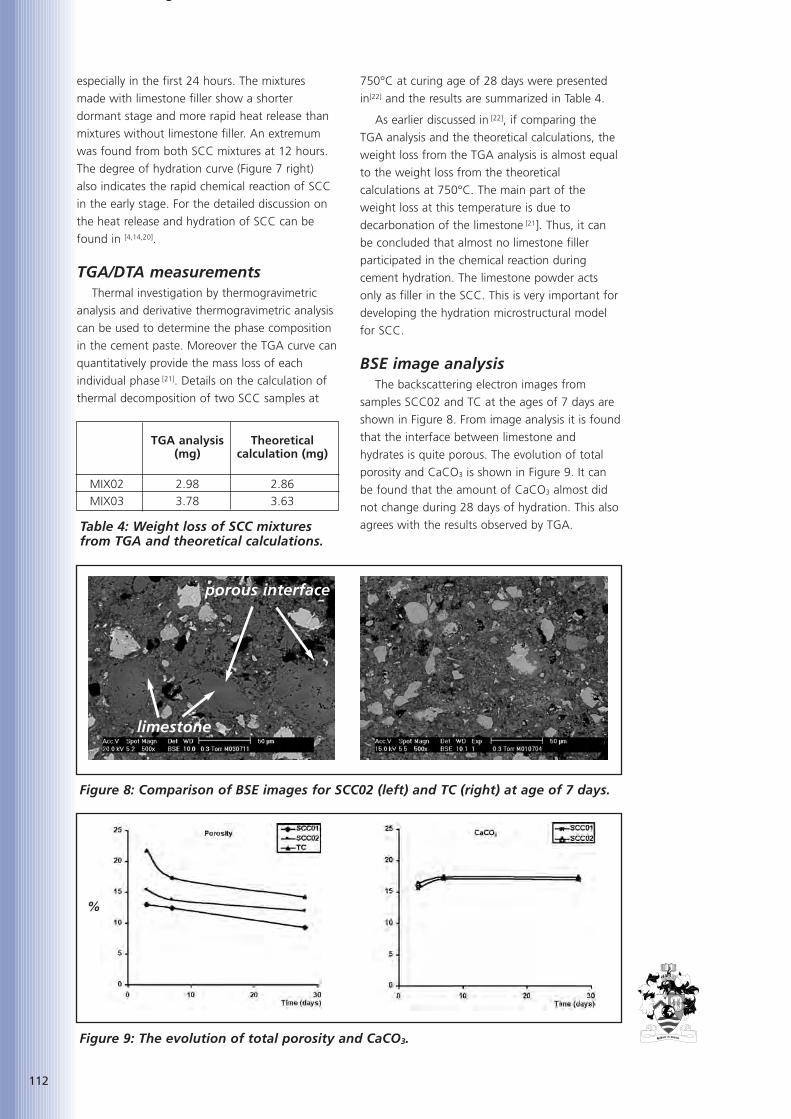
g
112
especially in the first 24 hours. The mixtures
made with limestone filler show a shorter
dormant stage and more rapid heat release than
mixtures without limestone filler. An extremum
was found from both SCC mixtures at 12 hours.
The degree of hydration curve (Figure 7 right)
also indicates the rapid chemical reaction of SCC
in the early stage. For the detailed discussion on
the heat release and hydration of SCC can be
found in [4,14,20].
TGA/DTA measurementsThermal investigation by thermogravimetric
analysis and derivative thermogravimetric analysis
can be used to determine the phase composition
in the cement paste. Moreover the TGA curve can
quantitatively provide the mass loss of each
individual phase [21]. Details on the calculation of
thermal decomposition of two SCC samples at
750°C at curing age of 28 days were presented
in[22] and the results are summarized in Table 4.
As earlier discussed in [22], if comparing the
TGA analysis and the theoretical calculations, the
weight loss from the TGA analysis is almost equal
to the weight loss from the theoretical
calculations at 750°C. The main part of the
weight loss at this temperature is due to
decarbonation of the limestone [21]. Thus, it can
be concluded that almost no limestone filler
participated in the chemical reaction during
cement hydration. The limestone powder acts
only as filler in the SCC. This is very important for
developing the hydration microstructural model
for SCC.
BSE image analysisThe backscattering electron images from
samples SCC02 and TC at the ages of 7 days are
shown in Figure 8. From image analysis it is found
that the interface between limestone and
hydrates is quite porous. The evolution of total
porosity and CaCO3 is shown in Figure 9. It can
be found that the amount of CaCO3 almost did
not change during 28 days of hydration. This also
agrees with the results observed by TGA.
TGA analysis Theoretical (mg) calculation (mg)
MIX02 2.98 2.86MIX03 3.78 3.63
Table 4: Weight loss of SCC mixturesfrom TGA and theoretical calculations.
Figure 8: Comparison of BSE images for SCC02 (left) and TC (right) at age of 7 days.
porous interface
limestone
Figure 9: The evolution of total porosity and CaCO3.
%
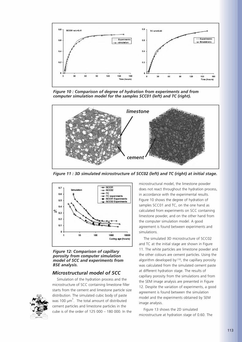
113
Microstructural model of SCCSimulation of the hydration process and the
microstructure of SCC containing limestone filler
starts from the cement and limestone particle size
distribution. The simulated cubic body of paste
was 100 µm3. The total amount of distributed
cement particles and limestone particles in the
cube is of the order of 125 000 – 180 000. In the
microstructural model, the limestone powder
does not react throughout the hydration process,
in accordance with the experimental results.
Figure 10 shows the degree of hydration of
samples SCC01 and TC, on the one hand as
calculated from experiments on SCC containing
limestone powder, and on the other hand from
the computer simulation model. A good
agreement is found between experiments and
simulations.
The simulated 3D microstructure of SCC02
and TC at the initial stage are shown in Figure
11. The white particles are limestone powder and
the other colours are cement particles. Using the
algorithm developed by [19], the capillary porosity
was calculated from the simulated cement paste
at different hydration stage. The results of
capillary porosity from the simulations and from
the SEM image analysis are presented in Figure
12. Despite the variation of experiments, a good
agreement is found between the simulation
model and the experiments obtained by SEM
image analysis.
Figure 13 shows the 2D simulated
microstructure at hydration stage of 0.60. The
Figure 10 : Comparison of degree of hydration from experiments and fromcomputer simulation model for the samples SCC01 (left) and TC (right).
Figure 11 : 3D simulated microstructure of SCC02 (left) and TC (right) at initial stage.
limestone
cement
Figure 12: Comparison of capillaryporosity from computer simulationmodel of SCC and experiments from BSE analysis.
%

114
particles with dark grey colour are limestone
powder. The calculated porosity of SCC02 and TC
at this hydration stage is 10% and 17.4%,
respectively. From Figure 13, it is noted that
limestone powder fills up the empty pore.
However, the porosity around the limestone filler
particles also is much bigger than the porosity
around the hydrated cement particles. This is
consistent with the experiments where the
interface between limestone filler and hydrates is
quite porous, even on the samples at the age of
28 days hydration.
PART III : EXPERIMENTAL DURABILITY EVALUATION OF SELF-COMPACTING CONCRETE WITH LIMESTONE FILLER
IntroductionAlthough SCC is a very promising cementitious
material, the actual application of SCC might be
somewhat riskful due to a lack of knowledge
concerning its actual durability. The degradation
mechanisms of a cementitious material are
greatly influenced by the permeability of the
material for potentially aggressive media and
there is an important interaction between ‘pore
structure’, ‘transport mechanism’ and
‘degradation’. The permeability itself is strongly
influenced by the pore structure of the material.
Furthermore, the ongoing degradation process
might have an influence on the pore structure of
the material. As the pore structure might be
different for SCC in comparison with traditional
concrete, due to the difference in composition,
some changes in durability behaviour might
occur. At this moment however, it is unclear how
significant these differences will be with regard to
the concrete in practice. A fundamental bottle
neck in this discussion is the lack of fundamental
insight in the transport behaviour of potentially
aggressive media in SCC. As the concept of SCC
is totally different from traditional concrete,
traditional models can not be extrapolated as
such without any verification. This is already
illustrated by the experimental and theoretical
investigation of hydration, carried out at the
Magnel Laboratory for Concrete Research.
According to [14] the hydration models valid for
traditional concrete have to be altered when
applied to SCC.
The transport mechanism in SCC, as well as its
relation with the durability of SCC is studied in
the Belgian research project ‘Transport properties
of potentially aggressive substances in self-
compacting concrete and relation with durability’,
sponsored by the Belgian Fund for Scientific
Research Flanders (F.W.O.-Vl.). The research
project is a cooperation between the Magnel
Laboratory for Concrete Research of Ghent
University, the Catholic University of Leuven, and
the Royal Military Academy of Brussels. The
ongoing research project has the following main
objectives: 1) theoretical and experimental study
of the transport behaviour of potentially
aggressive media in SCC; 2) experimental study of
the durability of SCC, and theoretical correlation
with the fundamental transport mechanisms.
Both objectives should lead to a better and
more fundamental knowledge of the durability
behaviour of the new cementitious material. In
this paper an overview of the first results on three
SCC mixtures and one traditional concrete (TC)
will be presented. An overview of the design and
methodology used for this project is given in[23,24].
Mixture proportionsIn the first stage, 4 concrete mixtures are
studied: 3 SCC and 1 TC. In the SCC mixtures, a
Figure 13: (left) 2D structure of SCC02 at a degree of hydration of 0.62, porosity10.0% (right) 2D structure of TC at a degree of hydration of 0.62, porosity 17.4%.
limestone
porousinterface

115
constant amount of fine particles (cement and
limestone filler) is considered: 600 kg/m3; as well
as a constant amount of sand and gravel,
respectively 853 kg/m3 and 698 kg/m3. The
amount of water is varied in order to obtain a
W/C ratio of 0.40, 0.46 and 0.55. For all mixtures
the same type of cement is used, namely Portland
cement CEM I 42.5 R. The amount of
superplasticizer (polycarboxylic ether) was
determined in order to obtain a suitable
flowability without segregation. Also the values
for the V-funnel (values between 5s and 10s), air
content (values between 1.5% and 3.0%) and
the U-box requiring self-levelling were measured.
For the TC mixture the same amount of cement
and water as for the SCC mixture 1 is taken. In
Table 5 the mixture proportions are given
together with the slump flow and the
compressive strength at 28 days measured on
concrete cubes 150 mm. Besides comparing
traditional concrete to self compacting concrete,
the influence of the W/C ratio is studied.
TRANSPORT PROPERTIESThe degradation mechanisms are greatly
influenced by the permeability of a material for
potentially aggressive substances. The penetration
of liquids and gasses in SCC is studied firstly by
means of basic tests, which should lead to the
determination of the fundamental parameters
governing the penetration behaviour of liquids
and gasses in SCC.
Water permeability Three concrete cubes 150 mm were stored in a
climate room at 20 ± 2°C and at least 90% r.h.
Until the age of 90 days. Then, from the centre
of each cube, one core, diameter 80 mm and
height 25 mm, was taken. Afterwards, these
cores were vacuum saturated in water and put in
the testing device. Water is present at the upper
side of the specimen and on the lower side there
is no water. Hence the pressure head is known
and the coefficient of permeability k [m/s] can be
calculated.
Capillary suctionThree concrete cubes 150 mm were stored in a
climate room at 20 ± 2°C and at least 90 % R.H..
At the age of 28 days, these cubes were stored
for two weeks at 35 ± 5°C and 40 ± 3% R.H..
The test was performed in an environment at 20
± 3°C and 60 ± 3% R.H.. The cubes were placed
on stable supports in water, so that the water
level is 5 ± 1 mm above the lower face of the
specimen. After 3, 6, 24, 72 and 168 hours the
mass of the specimens is determined. From these
results the sorptivity S [g/h] can be calculated.
Water absorption by immersion Three concrete cubes 100 mm were stored in a
climate room at 20 ± 2°C and more than 90%
R.H.. At the age of 28 days, these cubes were
stored for one week at 20 ± 3°C and 60 ± 3%
R.H.. Then the cubes are immersed in water until
the change in mass after 24 hours is less than
0.1%. The cubes are then placed in an oven at a
temperature of 105 ± 5°C until the difference in
mass after 24 hours is less than 0.1% and the
water absorption A [% of dry mass] was
determined.
Water vapour diffusion This method is based on DIN 52615
‘Bestimmung der Wasserdampfdurchlässigkeit von
Bau- und Dämmstoffen’. One cube 150 mm was
SCC1 SCC2 SCC3 TC1
CEM I 42,5 R [kg/m3] 360 360 360 360
limestone filler [kg/m3] 240 240 240
water [kg/m3] 165 144 198 165
river sand 0/5 [kg/m3] 853 853 853 640
river gravel 4/14 [kg/m3] 698 698 698 1225
superplasticizer [l/m3] 2.3 3.6 1.8
W/C [-] 0.46 0.40 0.55 0.46
W/(C+F) [-] 0.27 0.24 0.33 0.46
slump flow [mm] 685 740 820
compressive strength [N/mm2] 55 69 46 48
Table 5: Mix design.

116
made and stored in a climate room at 20 ± 2°C
and at least 90% R.H.. At the age of at least 28
days four cores with diameter 80 mm and height
20 mm were taken from this cube and further
stored at 20 ± 2°C and at least 90% R.H. until
the age of six months. The samples are put above
a reservoir with a saturated solution of a
hygroscopic salt NH4H2PO4 in water giving a layer
of air with a constant R.H. of 93% between the
sample and the water. The sample and the
reservoir are then put in a climate room at 20 ±
3°C and 60 ± 3% R. H.. In this way a constant
gradient of humidity has been created. The mass
of the testing device is measured on a regular
basis. This makes it possible to calculate the
decrease in mass of the water under the sample.
The water vapour diffusion coefficient D [m2/s]
can be calculated by analyzing the mass decrease
as a function of time.
Gas permeability The transport of oxygen is studied
fundamentally by means of a gas permeability
measuring instrument according the specifications
of RILEM TC 116-PCD "Permeability of concrete
as a criterion of its durability" [25]. One prism 400
x 400 x 100 mm is made and stored in a climate
room at 20 ± 2°C and more than 90% R.H.. At
the age of 28 days, three cores of 150 mm
diameter were drilled and from the centre of
these cores, samples with 50 mm height were
taken. Until the beginning of the test, at the age
of three months, the samples are stored in a
climate room at 20 ± 2°C and more than 90
%R.H.. In this paper, only the results of the tests
with an inlet pressure of 3 bar and at saturation
degree of 0% will be discussed. The drying of the
samples is performed according a fixed procedure
based on [26]. The apparent gas permeability kapp
[m2] can be calculated by means of a relationship
based on the Hagen-Poiseuille relationship for
laminar flow of a compressible fluid through a
porous body with small capillaries under steady-
state conditions [27,28].
Experimental results - DiscussionThe results of the tests on transport properties,
described above, are gathered in Table 6.
In general, the water permeability, water
absorption by immersion and the sorptivity of
SCC1 are compared to TC1 somewhat lower, but
the difference is rather small. The coefficient of
water vapour diffusion of SCC1 is lower than the
coefficient of TC1. The somewhat better
transport properties for liquid transport may be
due to the difference in porosity between SCC
and TC. A rather good relationship between the
capillarity porosity and the water permeability has
already been demonstrated [29]. The apparent gas
permeability of TC1 is about 5.5 times higher
than of SCC1. The much lower gas permeability
of SCC can also be noticed for the other SCC
mixtures.
Lowering the w/c ratio by decreasing the
amount of water decreases significantly the
values of the water transport properties. The
higher the amount of water, the bigger the
surplus of water not used by the hydration
process, causing a higher capillary porosity. Also
the gas permeability increases with an increasing
w/c ratio.
DURABILITYFrequently occurring degradation mechanisms
in which transport of aggressive substances is of
importance, are studied by means of several
experiments. Firstly, carbonation and chloride
penetration are investigated by means of tests
using special climate chambers and by immersion
in chloride containing solutions. Chloride
diffusivity was tested by means of an accelerated
method based on electrochemical principles.
Secondly, degradation mechanisms more
aggressive to the concrete itself were
investigated: physical degradation (frost, and frost
in combination with de-icing salts) and chemical
degradation (acid attack). The physical
degradation caused by carbonation and by
TC1 SCC1 SCC2 SCC3
water permeability K [10-11 m/s] 0.98 0.91 0.75 1.20
sorptivity S [g/h] 1.32 1.30 1.18 1.51
water absorption A [% of dry mass] 4.90 4.80 4.20 6.30
water vapour diffusion coefficient D [10-7 m/s] 2.95 2.00 1.71 3.03
apparent gas permeability kapp [m2] 3.018 0.544 0.271 1.382
Table 6: Transport properties.
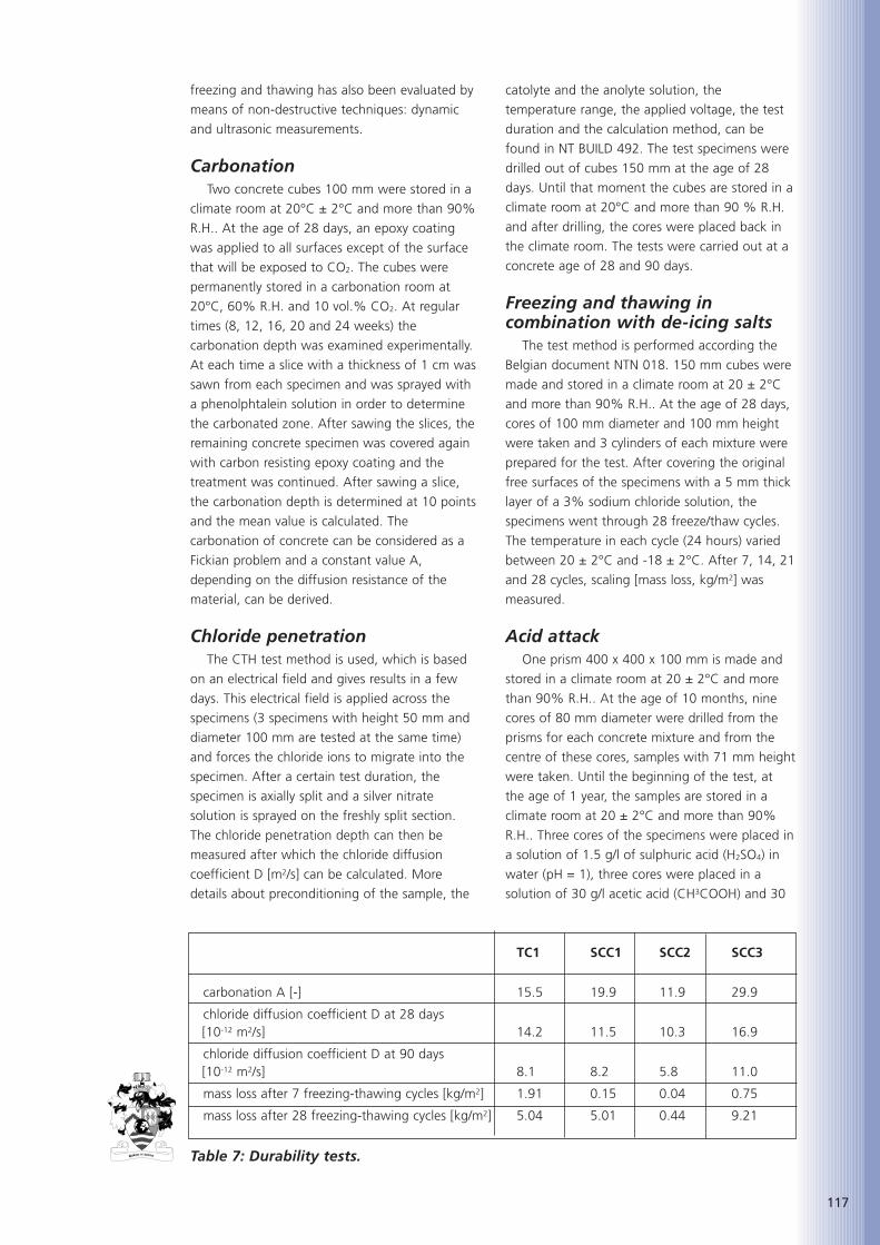
117
freezing and thawing has also been evaluated by
means of non-destructive techniques: dynamic
and ultrasonic measurements.
Carbonation Two concrete cubes 100 mm were stored in a
climate room at 20°C ± 2°C and more than 90%
R.H.. At the age of 28 days, an epoxy coating
was applied to all surfaces except of the surface
that will be exposed to CO2. The cubes were
permanently stored in a carbonation room at
20°C, 60% R.H. and 10 vol.% CO2. At regular
times (8, 12, 16, 20 and 24 weeks) the
carbonation depth was examined experimentally.
At each time a slice with a thickness of 1 cm was
sawn from each specimen and was sprayed with
a phenolphtalein solution in order to determine
the carbonated zone. After sawing the slices, the
remaining concrete specimen was covered again
with carbon resisting epoxy coating and the
treatment was continued. After sawing a slice,
the carbonation depth is determined at 10 points
and the mean value is calculated. The
carbonation of concrete can be considered as a
Fickian problem and a constant value A,
depending on the diffusion resistance of the
material, can be derived.
Chloride penetration The CTH test method is used, which is based
on an electrical field and gives results in a few
days. This electrical field is applied across the
specimens (3 specimens with height 50 mm and
diameter 100 mm are tested at the same time)
and forces the chloride ions to migrate into the
specimen. After a certain test duration, the
specimen is axially split and a silver nitrate
solution is sprayed on the freshly split section.
The chloride penetration depth can then be
measured after which the chloride diffusion
coefficient D [m2/s] can be calculated. More
details about preconditioning of the sample, the
catolyte and the anolyte solution, the
temperature range, the applied voltage, the test
duration and the calculation method, can be
found in NT BUILD 492. The test specimens were
drilled out of cubes 150 mm at the age of 28
days. Until that moment the cubes are stored in a
climate room at 20°C and more than 90 % R.H.
and after drilling, the cores were placed back in
the climate room. The tests were carried out at a
concrete age of 28 and 90 days.
Freezing and thawing incombination with de-icing salts
The test method is performed according the
Belgian document NTN 018. 150 mm cubes were
made and stored in a climate room at 20 ± 2°C
and more than 90% R.H.. At the age of 28 days,
cores of 100 mm diameter and 100 mm height
were taken and 3 cylinders of each mixture were
prepared for the test. After covering the original
free surfaces of the specimens with a 5 mm thick
layer of a 3% sodium chloride solution, the
specimens went through 28 freeze/thaw cycles.
The temperature in each cycle (24 hours) varied
between 20 ± 2°C and -18 ± 2°C. After 7, 14, 21
and 28 cycles, scaling [mass loss, kg/m2] was
measured.
Acid attack One prism 400 x 400 x 100 mm is made and
stored in a climate room at 20 ± 2°C and more
than 90% R.H.. At the age of 10 months, nine
cores of 80 mm diameter were drilled from the
prisms for each concrete mixture and from the
centre of these cores, samples with 71 mm height
were taken. Until the beginning of the test, at
the age of 1 year, the samples are stored in a
climate room at 20 ± 2°C and more than 90%
R.H.. Three cores of the specimens were placed in
a solution of 1.5 g/l of sulphuric acid (H2SO4) in
water (pH = 1), three cores were placed in a
solution of 30 g/l acetic acid (CH3COOH) and 30
TC1 SCC1 SCC2 SCC3
carbonation A [-] 15.5 19.9 11.9 29.9
chloride diffusion coefficient D at 28 days [10-12 m2/s] 14.2 11.5 10.3 16.9
chloride diffusion coefficient D at 90 days [10-12 m2/s] 8.1 8.2 5.8 11.0
mass loss after 7 freezing-thawing cycles [kg/m2] 1.91 0.15 0.04 0.75
mass loss after 28 freezing-thawing cycles [kg/m2] 5.04 5.01 0.44 9.21
Table 7: Durability tests.

118
g/l lactic acid (C3H6O3) in water (pH = 2.5), and
three cores were placed in water, all at a
temperature of 20°C. The variation of mass, due
to immersion, is followed by weighing the
specimens every week. The samples stay
immersed for a period of six weeks. After this
test, the samples are taken out from the solutions
and are put for two weeks in a climate room at
20 ± 2°C and more than 90 % R.H.. They are
prepared for a compression test in order to be
able to determine the remaining compressive
strength due to deterioration.
Experimental results - discussion The results of the tests on durability, described
above, are gathered in Table 7. SCC1 exhibits a
higher carbonation depth. At 28 days, the
chloride diffusion of SCC1 is lower than the
chloride diffusion of TC1. At 90 days, the chloride
diffusion is more or less the same. After 28
freezing-thawing cycles in combination with de-
icing salts, SCC1 and TC1 have an equivalent
mass loss. However at 7 days, the mass loss of
SCC1 is much lower. The mass loss in time
increased more rapidly for SCC1 than for TC1 for
immersion in a solution of lactic and acetic acid in
water. The mass loss of TC1 is bigger than that of
SCC1 for immersion in a solution of sulphuric
acid in water [30].
The carbonation depth and the chloride
diffusion increase with increasing w/c ratio.
Increasing the w/c ratio increases the mass loss
due to freezing and thawing in combination with
de-icing salts. The mass loss increases with an
increasing w/c ratio for immersion in a solution of
lactic and acetic acid in water. When the samples
are immersed in a solution of sulphuric acid in
water, the biggest mass loss is noticed for the
lowest w/c ratio [30].
Non-destructive testing has been performed
on SCC1 and TC1 subjected to carbonation and
freezing and thawing. For both mixtures, due to
carbonation no significant decrease of modulus
of elasticity was noticed. Due to freezing and
thawing there is a decrease in modulus of
elasticity, which was bigger for TC1 than for
SCC1.
Concerning durability of self-compacting
concrete, in relation with microstructure and
transport properties, more details can be found
in [31,32].
CONCLUSIONSIn some cases, the reaction mechanism of the
Portland cement is clearly influenced by the
addition of the limestone filler. The induction
period is shortened and an extra heat production
peak sometimes occurs, even at the lowest
testing temperatures. These phenomenons are
not found when a quartzite filler is used in the
mixes.
The heat production rate of the second peak is
clearly influenced by the presence of the
limestone filler. The higher the amount of filler
and the higher the testing temperature, the more
pronounced the peak is. A linear dependency of
the maximum heat production rate on the c/p
ratio can be accepted in a first approximation.
The hydration process and the microstructure
of SCC were investigated by heat release,
TGA/DTA and BSE imaging technique. It was
confirmed that the limestone powder in SCC acts
as accelerator during cement hydration at early
stage. However, from BSE image analysis and
TGA analysis, the total amount of limestone
powder did not change throughout the
hydration. Based on HYMOSTRUC3D model, the
microstructure of SCC was simulated and the
pore structure was analyzed. The evolution of
porosity simulated from the model agrees well
with the experiments from the BSE image
analysis. Further research will be paid on the
percolation of capillary porosity of SCC.
A first insight in the transport properties and
the durability behaviour of SCC has been
achieved. Further experimental research is going
on and it will be verified whether traditional
models concerning transport properties and
durability can be applied to the new cementitious
material.
REFERENCES
1. NOGUCHI, T. and MORI, H., State-of-the-artreport : Evaluation of fresh properties ofself-compacting concrete in laboratory andon site, in: OZAWA, K., OUCHI, M. (eds.),Proceedings of the international workshopon self-compacting concrete, Kochi 1998,p. 97-110.
2. OKAMURA, H. and OUCHI, M., Self-compacting concrete. Development, presentuse and future, in: SKARENDAHL, A.,PETERSSON, O. (eds.), Proceedings of thefirst International RILEM Symposium onSelf-compacting Concrete, Stockholm 1999,p. 3-14.
119
3. DE SCHUTTER, G. and TAERWE, L., Generalhydration model for portland cement andblast furnace slag cement, Cem Concr Res25 (3) (1995) 593-604.
4. DE SCHUTTER, G. Fundamental andpractical study of thermal stress inhardening massive concrete elements,Doctoral thesis (in Dutch), Ghent University,1996.
5. Van BREUGEL, K., Simulation of hydrationand formation of structure in cement basedmaterials, Doctoral thesis, TechnicalUniversity Delft, 1991.
6. Van BREUGEL, K., Numerical simulation ofhydration and microstructural developmentin hardening cement-based materials –theory, Cem Concr Res 25 (2) 1995, 319-331.
7. BILLBERG, P. Influence of filler characteristicson SCC rheology and early hydration, in:OZAWA, K., OUCHI, M. (eds.), Proceedingsof the Second International RILEMSymposium on Self-compacting Concrete,Tokyo 2001, p. 285-294.
8. SHARMA, R.L. and PANDEY, S.P., Influenceof mineral additives on the hydrationcharacteristics of ordinary portland cement,Cem Concr Res 29 (9) 1999, 1525-1529.
9. SARI, M., PRAT, E., LABASTIRE, J.F., Highstrength self-compacting concrete - Originalsolutions associating organic and inorganicadmixtures, Cem Concr Res 29 (6) 1999,813-818.
10. Kadri, E.H., Aggoun, S., Duval, R.,Influence of grading and diameter size ofadmixture on the mechanical properties ofcement mortars, in: Bilek, V., Kersner, Z.(eds.), Proceedings of the InternationalSymposium on Non-Traditional cement andconcrete, Brno 2002, p. 306-313.
11. Kadri, E.H., Duval, R., Effect of ultrafineparticles on heat of hydration of cementmortars, ACI Mater J 99 (2) 2002, 138-142.
12. Bensted, J., Some applications ofconduction calorimetry to cementhydration, Adv Cem Res 1 (1) 1987, 35-44.
13. Bonavetti, V.L., Rahhal, V.F., Irassar, E.F.,Studies on the carboaluminate formation inlimestone filler-blended cements, CemConcr Res 31 (6) 2001 853-859.
14. Poppe, A.M., Influence of fillers onhydration and properties of self-compactingconcrete, Doctoral thesis (in Dutch), GhentUniversity, 2004.
15. POPPE, A.M., DE SCHUTTER, G. ‘Analyticalhydration model for filler rich self-compacting concrete’, Journal of AdvancedConcrete Technology, Vol. 4, No. 2, June2006, 259-266.
16. VUK, T., et al. The effects of limestoneaddition, clinker type and fineness onproperties of Portland cement, Cement andConcrete Research, vol. 31 (1) 2001 pp.135-139.
17. PERA, J., et al, Influence of sinely roundlimestone on cement hydration, Cementand Concrete Research, vol. 21 (2) 1999 pp.99-105.
18. Van BREUGEL, K. ‘Simulation of Hydrationand Formation of Structure in HardeningCement-Based Materials’, PhD thesis, DelftUniversity of Technology, The Netherlands,1991.
19. YE, G. ‘Experimental study and numericalsimulation of the development of themicrostructure and permeability ofcementitious materials’, PhD thesis, DelftUniversity of Technology, The Netherlands,2003.
20. YE, G., LIU, X., DE SCHUTTER, G., POPPE,A.M., TAERWE, L., ‘Influence of limestonepowder used as filler in SCC on hydrationand microstructure of cement pastes’,Cement & Concrete Composites, 29, 2007,94-102.
21. BAZANT, Z.P., KAPLAN, M.F., Concrete athigh temperatures. Longman – Addison-Wesley, London, 1996.
22. YE, G., LIU, X., DE SCHUTTER, G., POPPE,A.M. and TAERWE, L., VANDEVELDE, P.,Phase distribution and microstructuralchanges of Self-Compacting Concrete atElevated Temperature submitted to Cementand Concrete Research 2005.
23. DE SCHUTTER, G., AUDENAERT, K., BOEL,V., VANDEWALLE, L., DUPONT, D.,HEIRMAN, G., VANTOMME, J.,D’HEMRICOURT, J., Transport properties inself-compacting concrete and relation withdurability: overview of a Belgian researchproject; 3rd international conference onSCC, 17/8/2003-20/7/2003, Reykjavik,RILEM - 2003. p. 799-807.
24. BOEL, V., AUDENAERT, K., DE SCHUTTER,G., HEIRMAN, G., VANDEWALLE, L.,DESMET, J., VANTOMME, J., ‘Transportproperties of self-compacting concrete withlimestone filler or fly ash’, accepted forpublication in Materials and Structures

120
25. RILEM, T.C., 116-PCD: Permeability ofConcrete as a Criterion of its Durability,Recommendations; Materials andStructures, Vol. 32, April 1999, pp 174-179
26. CARCASSÈS, M., ABBAS, A., OLLIVIER, J.-P.and VERDIER, J.; An optimisedpreconditioning procedure for gaspermeability measurement; Materials andStructures, Vol. 35, January / February2002, pp. 22-27
27. KHAN, M.I., ASCE M.; Permeation of HighPerformance Concrete; Journal of materialsin civil engineering, pp. 84-92; January /February 2003
28. KOLLEK, J.J.; The determination of thepermeability of concrete to oxygen by theCembureau method - a recommendation;Materials and Structures, Vol. 22; 1989, pp.225 - 230
29. AUDENAERT, K., DE SCHUTTER, G.; Waterpermeability of SCC; Advances in concretethrough science and engineering, Evanston,2004, CD-ROM, RILEM, paper 39 in sessionDurability, pp.9
30. BOEL, V., AUDENAERT, K., DE SCHUTTER,G.; Acid attack of self compacting concrete;ICCRRR 2005 (the International Conferenceon Concrete Repair, Rehabilitation andretrofitting), Cape Town, 2005.
31. AUDENAERT, K., Transport mechanisms inself-compacting concrete and relation withcarbonation and chloride penetration,Doctoral thesis (in Dutch), Ghent University,ISBN 90-8578-084-5, 2006.
32. BOEL, V., Microstructure of self-compactingconcrete in relation with gas permeabilityand durability, Doctoral thesis (in Dutch),Ghent University, ISBN 90-8578-113-2,2006.
121
Firstly the subject of new
concrete technology was
addressed excellently by the
speakers, albeit constrained by
the scale of the subject. We are
on a materials and technique
development escalator that will transform
concrete over the next 10 - 20 years. There are
many choices and options and there will be more.
I find that prospect exciting and motivating, I
hope you do too.
Of the 10 papers given, apart from the
keynote address, 4 were on performance
enhancement, 3 on assessment, 2 on
sustainability and 1 on design.
The keynote address by Professor Dhir gave
an historical framework about cement and
concrete. That gave the context of the
symposium and highlighted concrete's
adaptability and wide appeal as well as global
availability.
In addition, milestones in concrete's evolution
were identified, namely:
• Strength and w/c ratio,
• Durability,
• Modern specifications,
• Success and failures,
Removal of historical conventions and
replacement by modern thinking and materials
based on knowledge and proven performance.
It is important to identify the movers for
change within the construction industry so that
one can build confidence based on performance
retained in the long term.
The term citadel is very appropriate - this
stands for fortress, guarding or dominating.
Breaking down the conventions by way of
responsible and proven alternatives giving options
has to be right if concrete is to progress.
As to the other papers, they were of
substance and ongoing relevance and a number
of points should be made.
The search for low energy alternative cements
is addressing a global problem requiring global
solutions. I hope the patenting of such options
does not militate against widespread use. The
progress is noted and welcomed.
The development of site evaluation
techniques is important for performance,
reassurance and liability issues. There are still
problems of definition, interpretation and
quantification. As there were in the early days of
ground radar.
It is desirable to control the development of
the mechanical characteristics of concrete; control
the chemistry (new cement), control the physics -
macro fibres and related additions.
There was a fascinating paper on
petrographics and the development of dynamic
diagnostic techniques; assessing what is occurring
as it is occurring. This underwrites pre-emptive
maintenance. It is clear that this is happening in
the field of corrosion monitoring. We have seen
such instrumentation developments in motorcar
management systems. Might there be a similar
trend in buildings and construction? At this point
in the proceedings I became aware we were
being treated to a different way of thinking;
applying future industrialised processes to
construction - shades of Sir John Egan; rapid
prototyping in 2D and 3D as well as mega-scale
rapid manufacturing - a real flavour of
tomorrow’s world.
The lateral thinking continued with flexible
concrete arches. This is thinking outside of the
box - or rather outside of the arch! The idea is
beautifully simple and could have widespread
application.
Sustainability was raised for the second time in
the proceedings, dealing with recycled
aggregates. The first mention was of course the
low carbon dioxide releasing cements. We saw
the creation of an instant quarry by way of the
explosive demolition of a structure that was then
recycled.
Economics are a key factor with respect to
sustainability; perhaps some form of tax incentive
might improve competitiveness. The absence of
financial wellbeing will require legislation and/or
regulation if we want widespread application.
CEN TC350 and the Code for Sustainable Homes
(published in December 2006) may well demand
materials with a recycled content.
Concrete flooring is an important sector and
problems during use are unwelcome and can be
CHAIRMAN’S SUMMARY
Professor Peter Hewlett, PhD, LLD, BSc, CChem, FRSC, FIM, HonFICT
John Doyle Group plc / BBA

122
very disruptive. Automatic retrieval systems in
warehouses require flat and stable floors. Water
control is a factor but so is optimised particle
packing. This development could have a
significant impact.
It seemed right to finish the symposium with
self-compacting concrete since it has made a
major impact on practical concreting. I am sure
there will be variations of this concept, not least
of all cost containment. Low slump is one
convention or citadel we should discard.
We should not overlook the relationship
between novel and innovative materials that, of
themselves’ have benefit but have to be
incorporated into a design. The cost of running a
building far exceeds the initial cost to build and
therefore the retained performance is essential
and the design implications cannot be ignored.
The demands of modern construction will
require modern materials and concrete can be
that material - there is no alternative which has a
comparable engineering scale of use. Concrete is
no longer a simple composite, it is an interactive
and complex composite that can be manipulated.
The new technologies are only limited by our
imaginations.
I thank the ICT for bringing us together at this
symposium. I thank the speakers for stimulating
us and for producing detailed written papers that
will be published in the 07/08 ICT Yearbook. I
thank the exhibitors and you the audience who
have been engaged and attentive.


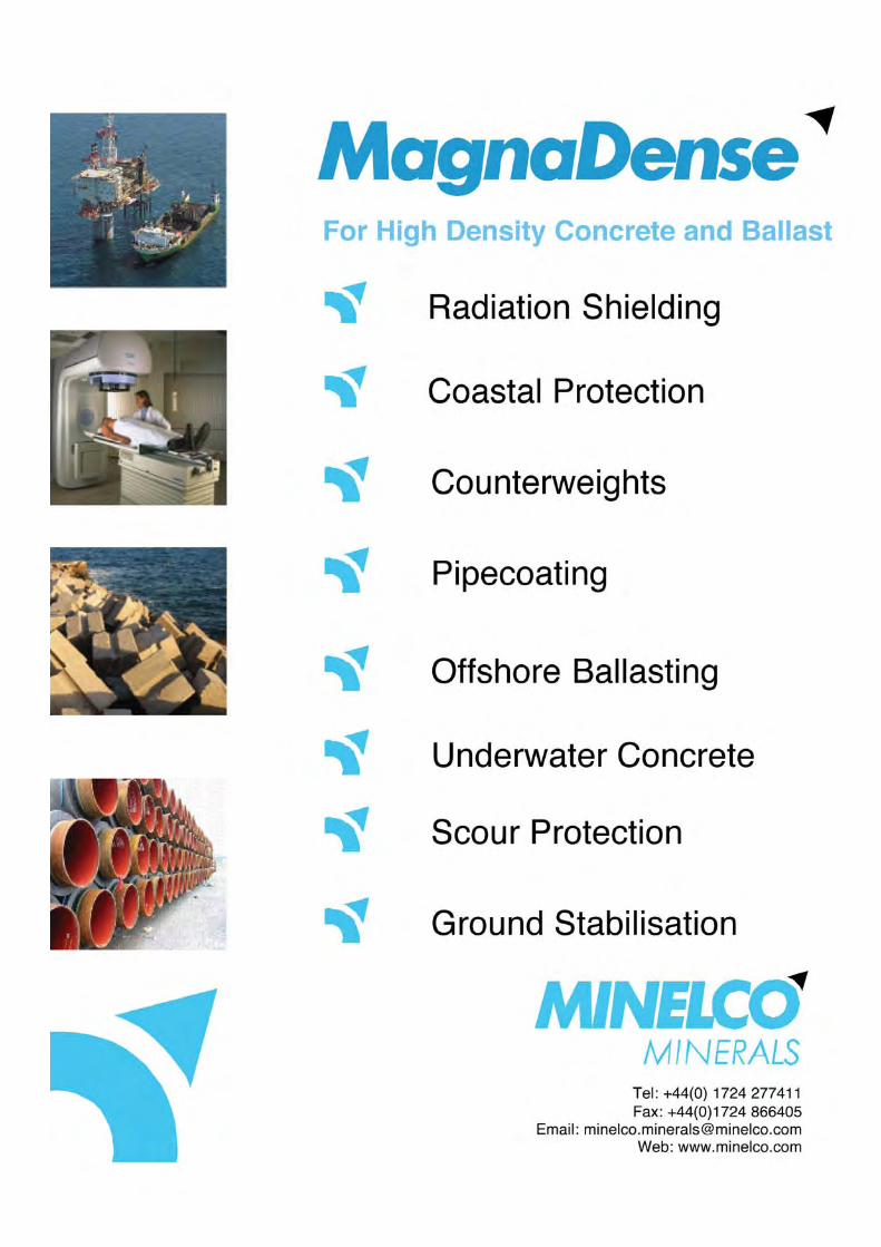


The Quality Scheme forReady Mixed Concrete
QSRMC
for quality concrete only the best is good enough
QSRMC’s Governing Board comprises designers, specifiers,purchasers, users and producers of ready mixed concrete
QSRMC’s expert staff have the experience and competence to ensureboth producers and consumers benefit from the highest standards
specify QSRMC by name
benefit from effective assurance
QSRMC 1 Mount Mews High Street Hampton TW12 2SH � 020 8941 0273Visit the quality concrete website: www.qsrmc.co.uk
For our certification services covering other products/systems: www.cpcert.co.uk

The event of the year
2008!
Put these dates in your diary NOW and we’ll see you there.
Full details will be circulated soon.
• Update
• Network
• Socialise
ICT ANNUAL
CONVENTION2008
Chesford Grange Hotel, Warwickshire
31 March to 2 April 2008
PROGRAMME31 March
Members Annual Meeting
1 AprilTechnical Symposium
R&D IN CONCRETE TECHNOLOGY- AN INTERNATIONAL VIEW
Convention dinner

Quattro (UK) Ltd is able to offer a range of servicesfrom convenient locations in West London.
Whatever your needs from aggregates to wastemanagement we have a solution.
We are pleased to offer a ‘one-stop’ service from our Park Royal Depot providing:
• Ready Mixed Concrete, for delivery or collection
• Primary and Reclaimed Aggregates
• Waste Transfer Facilities
For further information please contact our Sales Team
At Quattro (UK) LtdRegency Street
Off Victoria RoadPark Royal
LondonNW10 6NR
Tel: 020 8838 2648Fax: 020 8838 2741
Email: [email protected]
123
ADVANCED CONCRETE TECHNOLOGY DIPLOMA:
SUMMARIES OF PROJECT REPORTS 2006
The project reports are an integral and important part of the ACT Diploma.
The purpose of the projects is to show that the candidates can think about a topic or problem ina logical and disciplined way. The project normally spans some six months. Significant advances can bemade and several of the projects have evolved into research programmes in their own right.
Summaries of a selection of projects submitted during the 2005-2006 course are given in thefollowing pages.
PROJECT TITLE: AUTHOR:
AN EVALUATION OF THE PERFORMANCE OF Amit DawneerangenHIGH VOLUME FLY ASH CONCRETE
AN APPROPRIATE PIN PENETRATION TEST TO ESTIMATE Kevin Lester THE COMPRESSIVE STRENGTH OF CONCRETE
THE EVALUATION OF THREE POLYPROPYLENE FIBRES, AVAILABLE Andries P J Marais IN SOUTH AFRICA, DETERMINING THEIR ABILITY TO REDUCE: PLASTIC SHRINKAGE CRACKING, PLASTIC SETTLEMENT AND BLEEDING
EVALUATING SINGLE STAGE JAW CRUSHER VS. MULTI STAGE Suresh Rao M.CRUSHERS PRODUCED NAVI MUMBAI AGGREGATES PERFORMANCE IN CONCRETE
ANALYSIS OF THE EUROPEAN STANDARD EN 196-1 ‘METHODS David RevueltaOF TESTING CEMENT. PART 1: DETERMINATION OF STRENGTH’: ASSESSMENT OF THE INFLUENCE OF CEN STANDARD SAND
THE EFFECT OF (LETHABO) COARSE FLY ASH GRINDING ON Theo RoelofszSTRENGTH DEVELOPMENT AND WORKABILITY WHEN USED IN FLY ASH ACTIVATED CEMENT
A PRACTICAL APPROACH TO ACCELERATED STRENGTH N SurjooTESTING AND QUALITY CONTROL OF CONCRETE
A full list of earlier ACT projects, dating back to 1971 when the individual project was introduced as arequirement for the Advanced Concrete Technology Diploma examination, was published in the 2000 - 2001edition of the ICT yearbook.
Copies of the reports (except those that are confidential) are held in the Concrete Information Ltd (CIL) Libraryand these can be made available on loan. Subscribers to the CIL’s information service, Concquest, may obtaincopies on loan, free of charge. Requests should be addressed to: Concrete Information Ltd, 4 Meadows BusinessPark, Blackwater, Camberley GU17 9AB
ICT members may address their requests to: The Executive Officer, Institute of Concrete Technology at the sameaddress. Copies can then be obtained from CIL free of charge.

124
AN EVALUATION OF THE PERFORMANCE OF HIGH VOLUME FLY ASH CONCRETE
By: Amit Dawneerangen
SUMMARYThis project is an evaluation of the
performance of concrete mixes containingconventional and high volumes of South Africanfly ash. The stated objective is to “determine themaximum percentage of fly ash that will stillproduce an acceptable concrete in terms ofstrength, strength gain and durability by includinghigh range water reducing admixtures andaccelerators.”
The base cement type is, interestingly, notsimply a CEM I Portland cement but a slagcement with around 20% slag (similar to CEMII/A-S). Consequently, mixing the base cementwith fly ash produces the equivalent of a ternaryblended cement with compositions falling outsideEN 197-1. The fly ash content ranges from 20%to 70% of the total cementitious content.Various concrete mixes were investigated atwater/ binder ratios of 0.67, 0.56 and 0.45(water/binder = water/ (Portland cement + slag+fly ash)).
Concrete was tested for setting time, waterreduction, strength development and durability(as indicated by measurements of water sorptivity,air and oxygen permeability and chlorideconductivity).
It was found that the 28-day cube compressivestrength reduced with increasing fly ash contentfor any given level of water/binder ratio.Consequently, an increase in binder content isrequired compared to the base cement concrete.It was concluded that the cost-optimum mix for aC35 MPa grade concrete contained a binder with60% fly ash.
The early age strength development of thehigh volume fly ash mixes (fly ash content greaterthan 35% of total binder) was slower than thatof mixes with more conventional levels of fly ash.In contrast the strength gain between 7 and 28days and between 28 and 56 days was improved.At water/binder ratios below 0.56 acceptablelevels of compressive strength were produced.
In terms of durability related parameters it wasnoted that the air permeability measurements(using a Torrent Permeability Tester) fell into the‘good’ or ‘excellent’ categories except when thefly ash content was 70% and the water/binderratio was 0.67. Oxygen permeability tests andwater sorptivity measurements confirmed thepoor performance of the high fly ash highwater/binder mixes. The chloride conductivity testresults were quite variable but were again ratedas good or excellent at levels of fly ash below70%.
The report highlights the need for effectivecuring of high volume fly ash concrete (HVFA) inorder to develop optimum strength growth anddurability. It also recommends that tests areundertaken on concrete structures to confirm thefindings of the laboratory study.
The overall conclusion is that “ With thecurrent shortage of materials in the South Africanconstruction industry, consideration could begiven to the use of HVFA with 60% fly ash whichdisplays good compressive strength development,improved setting times using an accelerator, goodair permeability when effectively cured and agood durability test index performance. All thesefactors suggest that HVFA made from SouthAfrican raw materials will produce sound, durableconcrete capable of providing the South Africanconstruction industry with a cost-effectivesolution to its current situation”.

125
AN APPROPRIATE PIN PENETRATION TEST TO ESTIMATE THE COMPRESSIVESTRENGTH OF CONCRETE
By: Kevin Lester
SUMMARYA very large percentage of the cost of
construction is the cost of formwork. Ifformwork can be removed early it is possible tomaximise the number of uses and so makesavings. To be able to strip formwork, theconcrete must have gained sufficient strength tosafely support itself and any loads that it may besubject to.
Whilst a number of tests exist few are suitablefor measuring early strengths up to 10 MPa.Such determinations occur frequently. Forinstance in South Africa shotcrete when used aslining must achieve a compressive strength of 5MPa within eight hours.
Drilling cores is not practicable at low concretestrengths and pullout methods such as the LOKtest have the disadvantage of hiring equipmentand consumable costs.
Alternatives such as the Windsor Probe andWindsor Pin system are not a practical propositionin South Africa. However the Hilti Gun and theSchmidt Hammer are used although the latterrequires a hard surface to produce a reboundreading.
Faced with this situation the author decided tobuild a simple instrument for comparativeevaluation. Called the Leicester Pendulum it wasbased on the principle of a defined mass fallingthrough a given height, driving a pin into theconcrete. The instrument produced the sameenergy for every test, was simple to make anduse and required few consumables.
The project compared the ability of the HiltiGun, Windsor Pin, Leicester Pendulum and theSchmidt Hammer (including the N-type Hammer)to estimate in situ compressive strengths below10 MPa.
The results of the investigation suggest thatthe Hilti Gun, Windsor Pin and LeicesterPendulum may be suitable for estimating the in situ strength of concrete between 2-10 MPa.The N-type Schmidt Hammer was not suitable,because it did not give rebound readings at lowstrengths.

126
THE EVALUATION OF THREE POLYPROPYLENE FIBRES, AVAILABLE IN SOUTH AFRICA,DETERMINING THEIR ABILITY TO REDUCE: PLASTIC SHRINKAGE CRACKING, PLASTICSETTLEMENT AND BLEEDING
By: Andries P J Marais
SUMMARYThis project was carried out to compare the
effectiveness of three polypropylene fibres toreduce the occurrence of:
• Plastic shrinkage cracking
• Plastic settlement
• Bleeding
The fibres used were:
• Un-fluorinated 32µm polypropylene fibre(fibre A)
• Fluorinated 32µm polypropylene fibre(fibre B)
• 18µm polypropylene fibre imported fromAmerica (fibre C).
The testing of the fibres was carried out bycasting concrete slabs 995mm x 180mm x 50mmthick and testing the slabs in a wind tunnel at awind speed of 9m/s and temperature of 30°C forfive hours.
The following measurements were recordedand analysed:
• Time for first crack to appear
• Total number of cracks
• Maximum crack width
• Settlement in the mould
• Bleeding observations and testing.
The conclusions reached were:
1. When evaluated for plastic crack reducingand settlement reducing properties, fibreA had reduced capabilities whencompared to fibres B and C.
2. When evaluated for plastic crack reducingand settlement properties, there wereindications that fibre C was the mosteffective although taking regard of thetest methods used the difference betweenfibres B and C was marginal.
3. All three fibres reduced bleeding of theconcrete by more than 12%. Howeverfibre C performed better than fibres A and B.
4. On balance and under controlledreproducible conditions it was possible torank the fibre types according to theirplastic crack and settlement reducing andbleeding properties.
5. the ranking showed: Fibre C (18µm) > fibre B (32µm Fluorinated) > fibre A (32µm Un-fluorinated)

127
EVALUATING SINGLE STAGE JAW CRUSHER VS. MULTI STAGE CRUSHERS PRODUCEDNAVI MUMBAI AGGREGATES PERFORMANCE IN CONCRETE
By: Suresh Rao M.
SUMMARYThis project examines the effects of aggregates
produced using different types of crusher, on theperformance of concrete. In the Navi Mumbai(New Bombay) area, the majority of smalleraggregate producers utilise single stage jawcrushers (‘Category I producers’), whereas asmaller number of large producers (‘Category IIproducers’) now use multi stage crushers,combining primary jaw crushers with secondarycone crushers and tertiary vertical shaft impactcrushers.
A laboratory test programme was undertakento examine the effects of these different methodsof aggregate production on concreteperformance. For each aggregate (maximumaggregate size 20 mm), a series of concrete mixeswere made at cement contents (Portland cementonly) varying between 300 kg/m3 and 430 kg/m3.The concrete workability was targeted at a slumpof 100 mm and the admixture dosage wasmaintained at a fixed level of 1% by weight ofcement. The water requirement and strengthdevelopment were measured together with theproportion of fine aggregate required to achievea stable mix and uniformly combined aggregategrading.
Examination of the aggregate shapecharacteristics indicated that whilst the elongationindices of both Category I and Category IIaggregates were similar, the flakiness index of theCategory I aggregates was lower.
The results of the concrete testing showed thatthe water demand, at any given cement content,for the Category II aggregates was up to 8%lower than for the Category I aggregates. Alsothe optimum proportion of fine aggregate wasreduced.
In terms of concrete compressive strength, theCategory II aggregates performed better. For a28-day cube compressive strength of 45 MPa, thereduction in cement content when using theCategory II aggregates was typically around 25kg/m3 . However, it was also noted that thisdifference in cement content for a given strengthwas more pronounced at the higher strength,higher cement content end of the range ofcompositions studied.
The author points out that further studiesshould be carried out to confirm these findingswhen applied to other concrete properties such asflexural or tensile strength. It was also suggestedthat improved methods for the shapeclassification of aggregates are needed in order tounderstand better the causes of the observeddifferences in concrete performance.
128
SUMMARYThe inspiration for this project came from an
observation that when Spanish cement producerschanged the source of the standard sand used toproduce samples for cement strength testing,there was a distinct drop in strength. This wasdespite the fact that the new source of sandfulfilled all the requirements for such a sand in EN196-1.
The project report describes a detailedstatistical analysis of the acceptance proceduresfor the CEN Standard Sand in order to determinetheir reliability.
A source of sand for use in producing mortarprisms for cement strength testing must satisfytwo procedures:
• A certification test performed annuallycomparing the strength obtained for agiven cement on mortar prisms made withthe test sand with those made using theCEN reference sand. This test is performedon 20 sets of prisms for each of threecements (One from each of the EN 197-1strength classes 32,5: 42,5: 52,5). Therepeatability of the tests must be less than2%, expressed as coefficient of variation.If this is the case the difference in meanstrength (D) using the test sand and thereference sand must not exceed 5% of themean strength using the reference sand.
ANALYSIS OF THE EUROPEAN STANDARD EN 196-1 “METHODS OF TESTING CEMENT.PART 1: DETERMINATION OF STRENGTH”: ASSESSMENT OF THE INFLUENCE OF CENSTANDARD SAND
By: David Revuelta
• A verification test performed monthlycomparing the performance of the sandproduced each month with that of thesand used in the initial certification test.The test is performed on 10 sets of prismsusing cement from a single strength class.An analysis similar to the certification testis undertaken and D cannot be greaterthan 2.5% more than twice in a 12 monthperiod of sand production.
A statistical model was developed to analysethe certification and verification criteria for astandard sand described in EN 196-1 resulting inan ‘Operating-Characteristic Curve of the Test’(similar to the well known O-C curves of a sampleplan). This tool was used to show that the EN196-1 acceptance criteria were robust and able todetect even slight difference between a new sandsource and the CEN reference sand.
However, it was concluded that there were stillsome slight deficiencies in the requirements ofthe standard:
• The probability of acceptance changedepending on whether the proposed sandgenerates a higher or lower strength thanthe CEN reference sand (ie: the criteria areasymmetric)
• The standard does not state clearly thedifference between conformity criteria andacceptance criteria.

129
SUMMARYWith expanding construction activity in South
Africa, supplies of classified fly ash for use incement manufacture are becoming stretched.There are, however, abundant resources of coarseunclassified fly ash. The objective of this projectwas to investigate whether a ground, coarse flyash could be used as a substitute for classified flyash in the production of Portland-fly ash cement.
A coarse fly ash from Lethabo power station inSouth Africa (typically around 45% retained on45µm, SSA 2230 cm2/g) was ground in alaboratory mill to a fineness similar to that of aclassified fly ash (typically around 10% retainedon 45µm, SSA 2800 cm2/g). This ground materialwas then blended with an ISO EN 197-1 CEM I42,5N Portland cement to produce a CEM IV/APortland-fly cement with 40% fly ash. Bothmortars and concrete were produced using thiscement together with similar cements producedusing classified fly ash and un-ground coarse flyash
The results of the experimental programmerevealed that the grinding process destroyed ahigh proportion of the glassy spheres in the flyash. It also narrowed the particle size distributionof the fly ash (but not to the extent seen inclassified ash). Furthermore the grinding processintroduced ‘gaps’ in the particle size distributionnot seen in either the classified ash or the un-ground ash. These changes were reflected in theincreased water demand of the cementcontaining the ground ash. The standardconsistence of the cement pastes increased by17% when the ground ash was substituted forclassified material. However, there was still adegree of reduction in water demand comparedto a CEM I cement.
THE EFFECT OF (LETHABO) COARSE FLY ASH GRINDING ON STRENGTHDEVELOPMENT AND WORKABILITY WHEN USED IN FLY ASH ACTIVATED CEMENT
By: Theo Roelofsz
No significant effect of ash treatment (grindingor classification) was seen in the measurements ofsetting time.
Standard mortar prism strength tests (ISO EN196-1) carried out at a constant w/c ratioindicated that, compared to the un-ground ash,the cement made using ground fly ash showed a10% improvement in 28-day strength to a levelcomparable with cement containing classifiedash.
A similar situation was seen in the strength ofconcrete made at a fixed water/cement ratio. Theconcrete slump was, as expected, reduced whenthe ground ash cement was used. This clearlyindicated that the increase in cement waterdemand caused by the ash grinding process fedthrough to the concrete.
The overall conclusion from this work was thatthe increased mortar and concrete strengthsobtained using cement containing the ground ashwere not sufficient to overcome the effects of theincreased water demand. Consequently, using aground unclassified fly ash for the manufacture ofPortland-fly ash cement was not seen as anacceptable solution to the shortage of classifiedfly ash.
130
SUMMARYThe speed of modern construction makes the
use of 7-day strength results to predict 28-dayvalues questionable because the concrete towhich it relates might well be covered andinaccessible. As a result there is a need for arapid method of strength testing that can be usedas a quality control tool.
In the UK the current method is contained inBS 1881 Part 112: 1983 but its adoption in SouthAfrica has hardly progressed.
The primary objective of this investigation wasto assess whether a simple accelerated testingmethod could be adopted in South Africa toaccurately predict the 28-day strength of concreteat an earlier age.
This investigation was limited to using the55°C accelerated testing method:
• Two different types of cement/blends(100% CEM1 42.5N and 50-50% blend ofa CEM1 42.5N and ground granulatedblastfurnace slag were used
• The concrete incorporated a water-reducing admixture
• One type of crushed coarse aggregatefrom different batches was used
• A blend of crusher sand and fine fillersand was incorporated
• The strengths ranged from 10 MPa to 35MPa.
Other aspects that were considered were:
• A simple and feasible method that couldbe used under most working environmentswhere water and electricity were readilyavailable
A PRACTICAL APPROACH TO ACCELERATED STRENGTH TESTING AND QUALITYCONTROL OF CONCRETE
By: N Surjoo
• Judgement on the suitability of the regimefor practicable conditions
• The flexibility of the regime so that smalldeviations from the working instructionwould not significantly change thestrength results
• A warm water method (55°C) where thetemperature could be easily maintained
• Temperatures used were modest in orderto minimise health and safety risks.
The project concentrated on acceleratedconcrete specimen at 1 and 3 days. Conclusionsthat may be drawn:
1. Accelerated testing is a reliable method forquality control and estimating strengths atlater ages but requires a greater degree ofcontrol.
2. Cement type correlations may changefrom time to time.
3. The system used is basically simplealthough proper temperature control isnecessary for repeatable results.
4. The size of specimens and use ofadmixtures do not appear to affect theestimated strength relationship.
5. Considerable cost savings can beobtained.
6. It is recommended that the method beused for routine quality control ofconcrete.

ICT RELATED INSTITUTIONS & ORGANISATIONS
ASSOCIATION OFCONSULTING ENGINEERSAlliance House12 Caxton StreetLondon SW1H 0QLTel: 020 7222 6557www.acenet.co.uk
ASSOCIATION OF INDUSTRIALFLOORING CONTRACTORS33 Oxford StreetLeamington SpaCV32 4RATel: 01926 833 633www.acifc.org.uk
ASSOCIATION OF LIGHTWEIGHTAGGREGATE MANUFACTURERSWellington StRipleyDerbyshire DE5 3DZTel: 01773 746111
BRE (BUILDING RESEARCHESTABLISHMENT) LTDBucknalls LaneGarstonWatford WD25 9XXTel: 01923 664000www.bre.co.uk
BRITISH BOARD OF AGRÉMENTP.O.Box 195Bucknalls LaneGarstonWatfordHerts WD25 9BATel: 01923 665300www.bbacerts.co.uk
BRITISH CEMENT ASSOCIATION4 Meadows Business ParkStation Approach BlackwaterCamberley GU17 9ABTel: 01276 608700www.bca.org.uk
BRITISH PRECAST60 Charles StreetLeicester LE1 1FBTel: 0116 253 6161www.britishprecast.org.uk
BSI STANDARDSBritish Standards House389 Chiswick High RoadLondon W4 4ALTel: 020 8996 9000www.bsi.org.uk
BRITPAVEBritish In-Situ ConcretePaving Association4 Meadows Business ParkStation Approach BlackwaterCamberley GU17 9ABTel: 01276 33160www.britpave.org.uk
CEMENT ADMIXTURES ASSOCIATION38a Tilehouse Green LaneKnowleWest MidlandsB93 9EYTel: 01564 776362
CEMENTITIOUS SLAG MAKERS ASSOCIATIONCroudace HouseGoldstone RoadCaterhamSurrey CR3 6XQTel: 01883 331071www.ukcsma.co.uk
CIRIAConstruction Industry Research& Information Association
174-180 Old Street London EC1V 9BPTel: 020 7549 3300www.ciria.org.uk
CONCRETE ADVISORY SERVICE4 Meadows Business ParkStation Approach BlackwaterCamberley GU17 9ABTel: 01276 607140www.concrete.org.uk
CONCRETE BRIDGE DEVELOPMENT GROUP4 Meadows Business ParkStation Approach BlackwaterCamberley GU17 9ABTel: 01276 33777www.cbdg.org.uk
CONCRETE INFORMATION LTD4 Meadows Business ParkStation Approach BlackwaterCamberley GU17 9ABTel: 01276 608770www.concrete-info.com
CONCRETE REPAIR ASSOCIATIONTournai Hall, Evelyn Woods RoadAldershot GU11 2LLTel: 01252 357835www.cra.org.uk
THE CONCRETE CENTRE4 Meadows Business ParkStation Approach BlackwaterCamberley GU17 9ABTel: 01276 606800www.concretecentre.com
THE CONCRETE SOCIETY4 Meadows Business ParkStation Approach BlackwaterCamberley GU17 9ABTel: 01276 607140www.concrete.org.uk
CONSTRUCT4 Meadows Business ParkStation Approach BlackwaterCamberley GU17 9ABTel: 01276 38444www.construct.org.uk
CORROSION PREVENTION ASSOCIATIONTournai Hall, Evelyn Woods RoadAldershot GU11 2LLTel: 01252 357834www.corrosionprevention.org.uk
INSTITUTE OF CORROSIONCorrosion HouseVimy CourtLeighton BuzzardBeds LU7 1FG Tel: 01525 851771www.icorr.org
INSTITUTE OF MATERIALSMINERALS & MINING1 Carlton House TerraceLondon SW1Y 5DBTel: 020 7451 7300www.materials.org.uk
INSTITUTION OF CIVIL ENGINEERSOne Great George StreetLondon SW1P 3AATel: 020 7222 7722www.ice.org.uk
INSTITUTION OF HIGHWAYS& TRANSPORTATION6 Endsleigh StreetLondon WC1H 0DZTel: 020 7387 2525www.iht.org
INSTITUTION OFROYAL ENGINEERSBrompton BarracksChathamKent ME4 4UGTel: 01634 842669
INSTITUTION OFSTRUCTURAL ENGINEERS11 Upper Belgrave StreetLondon SW1X 8BHTel: 020 7235 4535www.istructe.org.uk
INTERPAVEConcrete Block Paving Association60 Charles StreetLeicester LE1 1FBTel: 0116 253 6161www.paving.org.uk
MORTAR INDUSTRY ASSOCIATION38-44 Gillingham StreetLondon SW1V IHUTel: 020 7963 8000www.mortar.org.uk
QSRMC1 Mount Mews High Street, HamptonMiddlesex TW12 2SHTel: 020 8941 0273www.qsrmc.co.uk
QUARRY PRODUCTS ASSOCIATION38-44 Gillingham StreetLondon SW1V IHUTel: 020 7963 8000www.qpa.org
RIBARoyal Institute of British Architects66 Portland PlaceLondon W1B 1ADTel: 020 7580 5533www.architecture.com
SOCIETY OF CHEMICAL INDUSTRY14/15 Belgrave SquareLondon SW1X 8PSTel: 020 7598 1500www.sci.mond.org
UNITED KINGDOM ACCREDITATION SERVICE21-47 High StreetFelthamMiddlesex TW13 4UNTel: 020 8917 8400www.ukas.org.uk
UNITED KINGDOM CAST STONE ASSOCIATION4 Meadows Business ParkStation Approach BlackwaterCamberley GU17 9ABTel: 01276 608771www.ukcsa.co.uk
UNITED KINGDOM QUALITY ASH ASSOCIATIONRegent HouseBath AvenueWolverhamptonWV1 4EGTel: 01902 576 586www.ukqaa.org.uk

TheINSTITUTE OF CONCRETE TECHNOLOGY
4 Meadows Business Park, Blackwater, Camberley, Surrey GU17 9AB
Tel/Fax: 01276 37831Email: [email protected] Website: www.ictech.org
THE ICTThe Institute of Concrete Technologywas formed in 1972 from the Associationof Concrete Technologists. Fullmembership is open to all those whohave obtained the Diploma in AdvancedConcrete Technology. The Institute isinternationally recognised and theDiploma has world-wide acceptance asthe leading qualification in concretetechnology. The Institute sets higheducational standards and requires itsmembers to abide by a Code ofProfessional Conduct, thus enhancingthe profession of concrete technology.The Institute is a Professional Affiliatebody of the UK Engineering Council. In 2007 the ICT merged with theConcrete Society to become theprofessional wing of the Society whilstretaining its own identity.
AIMSThe Institute aims to promote concretetechnology as a recognised engineeringdiscipline and to consolidate theprofessional status of practising concretetechnologists.
PROFESSIONAL ACTIVITIESIt is the Institute's policy to stimulateresearch and encourage the publicationof findings and to promotecommunication between academic andcommercial organisations. The ICTAnnual Convention includes a TechnicalSymposium on a subject of topicalinterest and these symposia are wellattended both by members and non-members. Many other technicalmeetings are held. The Institute isrepresented on a number of committeesformulating National and InternationalStandards and dealing with policymatters at the highest level. TheInstitute is also actively involved in theeducation and training of personnel inthe concrete industry and those enteringthe profession of concrete technologist.


