52
The Leader In Solid State Motor Control Technology Publication #: 890001-15-07 REDISTART DIGITAL RDB6 SERIES INSTRUCTION MANUAL BENSHAW

The Leader In
Solid State Motor ControlTechnology
Publication #: 890001-15-07
REDISTART DIGITAL
RDB6 SERIES
INSTRUCTION MANUAL
BENSHAW

Quick Start
General This quickstart guide provides the information necessary for the operator to set thestarter for basic operation. This manual should be read in its entirety before thestarter is put into service.
• Connect the incoming power connections to terminals L1, L2 and L3.• Connect the motor leads to T1, T2, and T3.• Connect the control wiring to TB1 on the control card, as shown in the following
diagram. USE ONLY THE START/STOP BUTTONS OR THE EXTERNALAUTO CONTROL.
• Turn on the power to the starter. The display should show the software releasenumber and then rdy. If not, refer to the starter diagnostics beginning on page38.
• See the programming chapter beginning on page 20 for a complete description ofprogramming procedures and parameter descriptions. The importantparameters to program are P1, P2, P3, P4, and P6.
• Provide a short Start/Stop sequence to the starter to check motor rotation. If themotor rotates backwards, swap any two power leads.
• Give a Start command and allow the motor to accelerate to speed.• If the motor doesn’t begin accelerating immediately, increase parameter P4. If it
takes off too quickly, decrease P4.• If the motor takes too long to accelerate, decrease P6. If the motor accelerates
too quickly, increase P6.
i
QUICK START GUIDE
.5AFU1
MOTORPOWER
UP TOSPEED
FAULT
CUSTOMER EXTERNALFIELD TRIPS
OPTIONAL
CONTROL
EXTERNAL AUTO
FAULT (L)
FAULT (N)EXTERNAL
EXTERNAL

Table of Contents
1. INTRODUCTION . . . . . . . . . . . . . . . . . . . . . . . . . . . . . . . . . . . . . . . 1
1.1 How To Use This Manual . . . . . . . . . . . . . . . . . . . . . . . . . . . . . . . . . . . 1
1.2 Product Description . . . . . . . . . . . . . . . . . . . . . . . . . . . . . . . . . . . . . . 2
2. TECHNICAL INFORMATION . . . . . . . . . . . . . . . . . . . . . . . . . . . . . . . 4
2.1 Physical Specifications. . . . . . . . . . . . . . . . . . . . . . . . . . . . . . . . . . . . . 4
2.2 Control Power . . . . . . . . . . . . . . . . . . . . . . . . . . . . . . . . . . . . . . . . . 4
2.3 Storage. . . . . . . . . . . . . . . . . . . . . . . . . . . . . . . . . . . . . . . . . . . . . . 5
2.4 EU Declaration of Conformity . . . . . . . . . . . . . . . . . . . . . . . . . . . . . . . . 6
2.5 Solid State Overload . . . . . . . . . . . . . . . . . . . . . . . . . . . . . . . . . . . . . . 7
2.6 Chassis Rating . . . . . . . . . . . . . . . . . . . . . . . . . . . . . . . . . . . . . . . . . 8
2.7 Standard and Heavy Duty Horsepower Ratings . . . . . . . . . . . . . . . . . . . . . . 8
2.8 Circuit Card Layout . . . . . . . . . . . . . . . . . . . . . . . . . . . . . . . . . . . . . . 10
2.9 Spare Parts . . . . . . . . . . . . . . . . . . . . . . . . . . . . . . . . . . . . . . . . . . . 11
3. INSTALLATION. . . . . . . . . . . . . . . . . . . . . . . . . . . . . . . . . . . . . . . . 12
3.1 Site Preparation. . . . . . . . . . . . . . . . . . . . . . . . . . . . . . . . . . . . . . . . . 12
3.2 EMC Installation guidelines . . . . . . . . . . . . . . . . . . . . . . . . . . . . . . . . . 12
3.3 Installation Procedures . . . . . . . . . . . . . . . . . . . . . . . . . . . . . . . . . . . . 13
3.4 CT Ratio Scaling Switches. . . . . . . . . . . . . . . . . . . . . . . . . . . . . . . . . . . 16
3.5 Hardware Deceleration Control . . . . . . . . . . . . . . . . . . . . . . . . . . . . . . . 17
3.6 Variable Voltage or Current Input . . . . . . . . . . . . . . . . . . . . . . . . . . . . . . 18
3.7 Door Mounted Display . . . . . . . . . . . . . . . . . . . . . . . . . . . . . . . . . . . . 18
4. OPERATING PARAMETERS . . . . . . . . . . . . . . . . . . . . . . . . . . . . . . . . 20
4.1 General Operating Parameter Information . . . . . . . . . . . . . . . . . . . . . . . . . 20
4.2 P1 - Motor Full Load Amps . . . . . . . . . . . . . . . . . . . . . . . . . . . . . . . . . . 21
4.3 P2 - Overload Multiplier . . . . . . . . . . . . . . . . . . . . . . . . . . . . . . . . . . . 21
4.4 P3 - Motor Thermal Overload . . . . . . . . . . . . . . . . . . . . . . . . . . . . . . . . 22
4.5 P4 - Initial Motor Starting Current . . . . . . . . . . . . . . . . . . . . . . . . . . . . . . 22
4.6 P5 - Maximum Motor Starting Current . . . . . . . . . . . . . . . . . . . . . . . . . . . 23
4.7 P6 - Motor Ramp Time . . . . . . . . . . . . . . . . . . . . . . . . . . . . . . . . . . . . 23
4.8 P7 - Motor Stall Time . . . . . . . . . . . . . . . . . . . . . . . . . . . . . . . . . . . . . 24
4.9 P8 - Deceleration Level 1 . . . . . . . . . . . . . . . . . . . . . . . . . . . . . . . . . . . 24
4.10 P9 - Deceleration Level 2 . . . . . . . . . . . . . . . . . . . . . . . . . . . . . . . . . . . 25
4.11 P10 - Deceleration Time . . . . . . . . . . . . . . . . . . . . . . . . . . . . . . . . . . . 25
4.12 P11 - Overcurrent Trip Level . . . . . . . . . . . . . . . . . . . . . . . . . . . . . . . . 26
4.13 P12 - Overcurrent Trip Time. . . . . . . . . . . . . . . . . . . . . . . . . . . . . . . . . 26
ii
TABLE OF CONTENTS

4.14 P13 - Undercurrent Trip Level. . . . . . . . . . . . . . . . . . . . . . . . . . . . . . . . 26
4.15 P14 - Undercurrent Trip Time . . . . . . . . . . . . . . . . . . . . . . . . . . . . . . . . 27
4.16 P15 - Line Phase Sensitivity . . . . . . . . . . . . . . . . . . . . . . . . . . . . . . . . . 27
4.17 P16 - Motor Current Imbalance . . . . . . . . . . . . . . . . . . . . . . . . . . . . . . . 28
4.18 P17 - Current Transformer Ratio . . . . . . . . . . . . . . . . . . . . . . . . . . . . . . 28
4.19 P18 - Meter Mode . . . . . . . . . . . . . . . . . . . . . . . . . . . . . . . . . . . . . . . 28
4.20 P19 - Meter Dwell Time . . . . . . . . . . . . . . . . . . . . . . . . . . . . . . . . . . . 29
4.21 P20 - Passcode . . . . . . . . . . . . . . . . . . . . . . . . . . . . . . . . . . . . . . . . . 29
4.22 P21 - 500% Current Kick Time. . . . . . . . . . . . . . . . . . . . . . . . . . . . . . . . 29
4.23 P22 - Starter Mode . . . . . . . . . . . . . . . . . . . . . . . . . . . . . . . . . . . . . . 30
5. OPERATING PROCEDURES . . . . . . . . . . . . . . . . . . . . . . . . . . . . . . . . 31
5.1 Pushbutton Functions . . . . . . . . . . . . . . . . . . . . . . . . . . . . . . . . . . . . . 31
5.2 Starting The Motor . . . . . . . . . . . . . . . . . . . . . . . . . . . . . . . . . . . . . . . 32
5.3 Operating Messages . . . . . . . . . . . . . . . . . . . . . . . . . . . . . . . . . . . . . . 35
5.4 Fault Codes . . . . . . . . . . . . . . . . . . . . . . . . . . . . . . . . . . . . . . . . . . . 36
5.5 Preventative Maintenance. . . . . . . . . . . . . . . . . . . . . . . . . . . . . . . . . . . 37
5.6 Starter Diagnostics . . . . . . . . . . . . . . . . . . . . . . . . . . . . . . . . . . . . . . . 38
5.7 Default Settings. . . . . . . . . . . . . . . . . . . . . . . . . . . . . . . . . . . . . . . . . 41
6. DISPLAY TEMPLATE . . . . . . . . . . . . . . . . . . . . . . . . . . . . . . . . . . . . 43
6.1 Door Mounted Display Template . . . . . . . . . . . . . . . . . . . . . . . . . . . . . . 43
7. INSIDE DELTA OPTION . . . . . . . . . . . . . . . . . . . . . . . . . . . . . . . . . . 44
TABLE OF CONTENTS
iii

1.1 How To Use This Manual
General Information The RediStart Digital motor starter operations manual provides the followinginformation:
• Specifications.• Installation site requirements.• Installation.• Programming.• Operation.• Diagnostics.
How to Use this Manual The operations manual is divided into five sections:• Introduction.• Technical information.• Installation procedures.• Operating parameters.• Operating procedures.
Each section contains subsections with detailed information on the relative topics.The subsections contain general information, details and any necessary precautionsabout the individual topics. The specific information contained in the subsections canbe found quickly and easily by reviewing the subject headings on the left margin.
Operations Manual The operations manual can be found on-line at:On-Line http://www.benshaw.com
The manual is available in Adobe Acrobat portable document format (pdf). Adobe andAcrobat are trademarks of Adobe Systems Incorporated.
Parameter Chart There is a parameter chart on page 41 of the manual. This parameter chart lists eachoperating parameter with its name, values and defaults. A space is provided on thechart for the user’s current parameter settings. When the operating parameters areset for the current application, they should be listed on the chart for future reference.
1
1. INTRODUCTION
1.2 Product Description
General Information The RediStart Digital motor starter is a microprocessor-controlled starter for single orthree-phase induction motors. The starter can be custom designed for specificapplications.
The starter offers:• Solid state design.• Current limited reduced voltage starting.• Closed-loop motor current control.• Programmable motor protection.• Programmable operating parameters.• Programmable metering.
Available in NEMA (National Electrical Manufacturers Association) specified framesizes, the starter may be used in numerous industrial applications. Each starter canoperate within applied voltage and frequency values of 100VAC to 600VAC (optional1000VAC) and 23 to 75Hz. This feature enables the RDB6 to be installed in a widerange of sites and countries.
The starter can be programmed for any motor FLA and all of the common motorservice factors. It enables operators to control both motor acceleration anddeceleration. It also protects the motor and its load from damage that could be causedby incorrect phase order wiring.
The starter continually monitors the amount of current being delivered to the motor.This protects the motor from overheating or drawing excess current. The starter willautomatically stop the motor if the line-to-line current is not within acceptable rangesor if the current is lost in a line.
Features The enhanced engineering features of the starter include:• Multiple frame sizes.• Universal voltage operation.• Universal frequency operation.• Programmable motor overload multiplier.• Controlled acceleration and deceleration.• Phase rotation protection.• Regulated current control.• Electronic motor thermal overload protection.• Electronic over/under current protection.• Single phase protection.• Line-to-line current imbalance protection.• Stalled motor protection.• Programmable metering.• Passcode protection.
2
1. INTRODUCTION

Optional Features Depending on the system configuration and customer specifications, the starter can becustomized to include:
• Door mounted keypad/display.• Over and under voltage relays.• Voltage unbalance sensors.• Over and under current relays.• Current unbalance sensors that also detect single-phase fault conditions.• Ground fault relays.• Motor protection systems.• Display indicator lights mounted on the cabinet.• External overload relays.• Meters or metering packages.• Circuit disconnecting devices.
Components The major components of the starter are:• Customized line and load lugs or pads.• Six (three-phase) or four (single-phase) SCRs with SIOV protection.• Printed circuit assembly control card.• Terminals for two-wire or three-wire 120VAC control.• Current feedback transformers.• An isolated heat sink with dual-SCR flat packs or a live heat sink with
puck-shaped SCRs.
LED Display A three character, alphanumeric LED display located on the control card (or on theoptional door mounted display) displays:
• Status information.• Operating parameters.• Fault codes.• Thermal Overload Content.• Motor current.• Motor current imbalance percentage.
Control Relays The starter has four control relays:• Start/Stop input relay.• Fault output relay.• UTS (up to speed) output relay.• Motor power output relay.
3
1. INTRODUCTION

2.1 Physical Specifications
General Information The physical specifications of the starter vary depending upon its configuration. Theconfiguration is determined by the applicable motor current and its specificapplication requirements.
Heat sink The starter uses one of two distinct types of heat sinks:• An isolated heat sink with dual SCR flat packs on RDB-27 to RDB-96 models.• A live heat sink with puck-style SCRs on RDB-124 to RDB-720 models.
Dimensions The chassis sizes are given in the following chart;
Catalog #Chassis Size
( H” x W” x D” )
RDB-27 14 x 10 x 6
RDB-40 14 x 10 x 6
RDB-52 16 x 10 x 7
RDB-65 16 x 10 x 7
RDB-77 16 x 10 x 7
RDB-96 16 x 10 x 7
RDB-124 16 x 12 x 9
RDB-156 16 x 12 x 9
RDB-180 18 x 12 x 10
RDB-240 20 x 14 x 10
RDB-302 20 x 14 x 10
RDB-361 20 x 14 x 10
RDB-477 35 x 16 x 12
RDB-590 35 x 16 x 12
RDB-720 35 x 16 x 12
2.2 Control Power
Chassis VA Requirements The power requirements for each starter size is given in the table:
Catalog #Transformer
Requirements (VA)
RDB-27 50
RDB-40 50
RDB-52 80
RDB-65 80
RDB-77 80
RDB-96 80
RDB-124 70
RDB-156 70
RDB-180 70
RDB-240 80
RDB-302 125
RDB-361 125
RDB-477 275
RDB-590 275
RDB-720 275
4
2. TECHNICAL INFORMATION

Total VA Requirements The power requirements of the complete starter package also depend on the otherdevices in the package. The VA requirements of some common devices are:
• 4” fan - 23VA• 6” fan - 42VA• Pilot Light - 3VA• Control Relay - 5VA
The VA requirements of the control card and any other devices in the package must beadded together. Multiply the total by 1.2 to get the minimum transformer sizerequired.
Control Terminals The TB1 terminal block has the following control terminal configuration:• TB1-1 Control power - Line.• TB1-2 Control power - Neutral.• TB1-3 Run relay holding contact.• TB1-4 Run relay line.• TB1-5 Run relay neutral.• TB1-6 Fault contact N.O. (not faulted).• TB1-7 Fault contact common.• TB1-8 Fault contact N.C. (not faulted).• TB1-9 Up-to-speed contact N.O. (not at full speed).• TB1-10 Up-to-speed contact common.• TB1-11 Up-to-speed contact N.C. (not at full speed).• TB1-12 Motor power N.O. (When motor is stopped).• TB1-13 Motor power common.• TB1-14 Motor power N.C. (When motor is stopped).• TB1-15 External trip input line (120VAC applied or trip occurs).• TB1-16 External trip input neutral.
• TB2-1 Internal power for potentiometer voltage control.• TB2-2 Voltage or current control signal input.• TB2-3 Voltage or current control signal common.
Output Contact Ratings Fault Relay:2A resistive, 1A inductive, 125VAC
Up-to-Speed Relay & Motor Power Relay:16A resistive, 8A inductive, 250VAC
2.3 Storage
General If the starter is to be stored for a significant period of time before being installed,certain storage environmental conditions must be maintained.
NOTE: The suggested maximum storage length is two years.
Environmental Conditions To protect the starter during the storage period the following environmentalconditions must be maintained:
• -40 degrees Fahrenheit to 158 degrees Fahrenheit (-40 degrees Centigrade to 70degrees Centigrade).
• 20% to 95% relative humidity (non-condensing).
The maximum acceptable temperature and humidity changes in 30 minutes are:• 10.8 degrees Fahrenheit (6 degrees Centigrade).• 10% humidity.
5
2. TECHNICAL INFORMATION

2.4 EU Declaration of Conformity
According to the EMC – Directive 89/336/EEC as Amended by 92/31/EEC and 93/68/EEC
Product Category: Motor Controller
Product Type: Reduced Voltage Solid State Motor Controller
Model Numbers: RDB6
Manufactures Name: Benshaw, Inc.
Manufacture’s Address: 1659 East Sutter RoadGlenshaw, PA USA15116
The before mentioned products comply with the following EU directives and Standards:
Safety: UL 508 Standard for Industrial Control Equipment covering devices for starting,stopping, regulating, controlling, or protecting electric motors with ratings of 1500volts or less.
EMC: EN 50081-2 Emissions Radiated/ConductedEN 55011/05.98+A1:1999
EN 50082-2 Immunity/Susceptibility which includes:EN 61000-4-2 Electrostatic DischargeEN 61000-4-3 Radiated RFEN 61000-4-4 Electrical Fast Transient/BurstEN 61000-4-6 Injected Currents
The technical files and other documentation are on file at Benshaw, Inc. and controlled by the Product EngineeringGroup. Benshaw, Inc. has internal production control systems that ensures compliance between the manufacturedproducts and the technical documentation.
The product is CE marked in April 2000.
Brian Seman Harry HagertyQuality Control Manager Advanced Controls and Drives Manager
Charles E. CookProduct Development Manager
6
2. TECHNICAL INFORMATION

2.5 Solid State Overload
General The starter incorporates an electronic overload which allows the user to select a class10, 20, or 30 overload. The following curves serve to define the different overloadclasses.
The thermal overload trip time will be lowered once the motor has been operated. Seepage 33 for a compete description of the overload operation.
7
2. TECHNICAL INFORMATION
1
10
100
1000
10000
100000
1 2 3 4 5 6 7 8 9 10
Current (Multiples of FLA)
Tim
e(S
eco
nd
s)
Class 30
Class 20
Class 10

2.6 Chassis Rating
CatalogNumber
NominalCurrent
(A)
115%CurrentRating
(A)
UnitWithstand
Rating(KA)
Fuse/Circuit Breaker Protected Rating
Fuse Class/CircuitBreakerCat.No.
Max FuseCurrent
Rating/TripPlug, A
Short CircuitRating, KA
RDB-27 27 31 5 Class J/T 5
RDB-40 40 46 5 Class J/T 5
RDB-52 52 59.8 5 Class J/T 5
RDB-65 65 75 5 Class J/T 5
RDB-77 77 89 5 Class J/T 5
RDB-96 96 110 10 Class J/T 10
RDB-124 124 179 10 Class J/T 10
RDB-156 156 143 10 Class J/T 10
RDB-180 180 207 10 Class J/T 10
RDB-240 240 276 10 Class J/T 10
RDB-302 302 347 18 Class J/T 18
RDB-361 361 415 18 Class J/T 18
RDB-477 477 549 30 Class J/T 30
RDB-590 590 679 30 Class J/T 30
RDB-720 720 828 30 Class J/T 30
2.7 Standard and Heavy Duty Horsepower Ratings
General There are 15 different RDB chassis sizes. Each frame size has two differenthorsepower ratings depending on the application.
Standard Duty Rating The standard duty horsepower rating is for normal motor starting. The standard dutyrating is a motor current that is 350% (3.5 times) of the full-load current for 30seconds. The standard duty rating table lists the maximum size of motor that can bestarted by each RDB unit.
Catalog #Nominal
Current (A)Horsepower Rating (hp for listed VAC)
208 220-240 440-480 600
RDB-27 27 7.5 10 20 25
RDB-40 40 10 15 30 40
RDB-52 52 15 20 40 50
RDB-65 65 20 25 50 60
RDB-77 77 25 30 60 75
RDB-96 96 30 40 75 100
RDB-124 124 40 50 100 125
RDB-156 156 50 60 125 150
RDB-180 180 60 75 150 200
RDB-240 240 75 100 200 250
RDB-302 302 100 125 250 300
RDB-361 361 125 150 300 400
RDB-477 477 150 200 400 500
RDB-590 590 200 250 500 600
RDB-720 720 250 300 600 700
8
2. TECHNICAL INFORMATION

Heavy Duty Rating The heavy duty rating is for heavy duty motor starting. The heavy duty rating is astarting current that is up to 500% (5 times) of the full-load current for 30 seconds.The heavy duty rating table lists the maximum size of motor that can be started byeach RDB unit.
Catalog #Nominal
Current (A)
Horsepower Rating (hp for listed VAC)
208 220-240 440-480 600
RDB-27 27 7.5 10 20 25
RDB-40 40 10 10 25 30
RDB-52 52 10 15 30 40
RDB-65 65 10 15 30 40
RDB-77 77 10 15 30 40
RDB-96 96 25 30 60 75
RDB-124 124 30 40 75 100
RDB-156 156 30 40 75 100
RDB-180 180 60 75 150 200
RDB-240 240 75 100 200 250
RDB-302 302 75 100 200 250
RDB-361 361 75 100 200 250
RDB-477 477 100 125 250 300
RDB-590 590 150 200 400 500
RDB-720 720 200 250 500 600
9
2. TECHNICAL INFORMATION

2.8 Circuit Card Layout
10
2. TECHNICAL INFORMATION
FU1 CONTROL
JP1 DECELTP3 GROUND
ASSEMBLY
TB1
TB1
TB1
TB1
TB1
TB1
TB2
TB3
LED7
DISP1
1 2ON
SW1-SW4PUSHBUTTONSWITCHES SWITCH
DIPS1
TP1
TB9
LED5,6
TB8
TB7
LED3,4
TB6
TB5
LED1,2
TB4
FUSE
OVERRIDE NUMBER
CONTROLPOWER
START/STOP
FAULTRELAY
UP TOSPEEDRELAY
MOTORPOWERRELAY
EXTERNALFAULT
ANALOGINPUT
CTINPUTS
POWERGOOD
LED
+5VDC
SCR6
SCRSTATUS
SCR3
SCR5
SCRSTATUS
SCR2
SCR4
SCRSTATUS
SCR1
TB2 +24VDC
CON1
DIAGNOSTICS UART
CON2
SW4SW3SW2SW1
PARAMETER UP DOWN ENTER
THERMAL RESET
DISP1
PWRGOOD
OVERRIDEDECEL
+VDC
GND
K2
K3
K4
FU1

2.9 Spare Parts
General The following lists the spare parts for the different starter sizes:
Part Number Description Used On Quantity
BIPCDMS control card all 1
BI-M-FU1 control card fuse all 1
BISCR5012X 50 amp dual flat pack SCR RDB-27, RDB-40 3
BISCR10012X 100 amp dual flat pack SCR RDB-52, RDB-65, RDB-77 3
BISCR13212X 132 amp dual flat pack SCR RDB-96 3
BISCR????? 218 amp puck style SCR RDB-124, RDB-156 6
BISCR6601218 660 amp puck style SCR RDB-180, RDB-240RDB-302, RDB-361
6
BISCR15001850 1500 amp puck style SCR RDB-477, RDB-590, RDB-720 6
BICT2881M 288:1 ratio current transformer RDB-27, RDB-40RDB-52, RDB-65
3
BICT8641M 864:1 ratio current transformer RDB-77, RDB-96RDB-124, RDB-156
3
BICT26401M 2640:1 ratio current transformer RDB-180, RDB-240RDB-302, RDB-361
3
BICT57601M 5760:1 ratio current transformer RDB-477, RDB-590, RDB-720 3
RSC-18 30A AC-1 rated bypass contactor RDB-27 1
RSC-32 45A AC-1 rated bypass contactor RDB-40 1
RSC-50 70A AC-1 rated bypass contactor RDB-52, RDB-65 1
RSC-65 80A AC-1 rated bypass contactor RDB-77 1
RSC-85 100A AC-1 rated bypass contactor RDB-96 1
RSC-100 150A AC-1 rated bypass contactor RDB-124 1
RSC-125 160A AC-1 rated bypass contactor RDB-156 1
RSC-150 210A AC-1 rated bypass contactor RDB-180 1
RSC-220 275A AC-1 rated bypass contactor RDB-240 1
RSC-300 350A AC-1 rated bypass contactor RDB-302 1
RSC-400 450A AC-1 rated bypass contactor RDB-361 1
RSC-600 660A AC-1 rated bypass contactor RDB-477, RDB-590 1
RSC-800 840A AC-1 rated bypass contactor RDB-720 1
BIOT Over temperature Switch all 1
11
2. TECHNICAL INFORMATION

3.1 Site Preparation
General Information Before the starter can be installed, the installation site must be prepared. Thecustomer is responsible for:
• Providing the correct power source.• Selecting the control mechanism.• Obtaining the connection cables.• Ensuring the installation site meets all environmental specifications for the
enclosure NEMA rating.• Installing the motor.
Connection Cables The connection cables for the starter must have the correct current NEC/CSA ratingfor the unit being installed. Depending upon the model, the connection cables canrange from a single #14 AWG conductor to four 750 MCM cables.
Site Requirements The installation site must adhere to the applicable starter NEMA/CEMA rating. Foroptimal performance, the installation site must meet the following specifications:
• Temperature: 32 degrees Fahrenheit to 104 degrees Fahrenheit (0 degreesCentigrade to 40 degrees Centigrade).
• Humidity: 20% to 95% non-condensing.• Airways: Clearances are provided around all heat sinks.• Altitude: Less than 3300 feet (1000 meters) above sea level.
NOTE: At altitudes greater than 3300 feet (1000 meters) above sea level, the startersize must be derated 1% for every 330 feet (100 meters) above this level.
Mounting The starter must be mounted so the heat sink fins are vertically oriented in an areathat does not experience excessive shock or vibration. All models require airwaypassages around the heat sink. During normal operation the heat sink may reach 194degrees Fahrenheit (90 degrees Centigrade). Do not install the starter in directcontact with any materials that cannot withstand these temperatures.
3.2 EMC Installation guidelines
General In order to help our customers comply with European electromagnetic compatabilitystandards, Benshaw Inc. has developed the following guidelines.
Attention: This product has been designed for Class A equipment. Use of the productin domestic environments may cause radio interference, in which case the installermay need to use additional mitigation methods.
Enclosure Install the product in a grounded metal enclosure.
Grounding Connect a grounding conductor to the screw or terminal provided as standard on eachcontroller. Refer to layout/power wiring schematic for grounding provision location.
Wiring Wire in an industrial application can be divided into three groups: power control andsignal. The following recommendations for physical separation between these groupsare provided to reduce the coupling effect;
• Different wire groups should cross at 90 degrees inside an enclosure.• Minimum spacing between different wiring groups in the same tray should be
six inches.• Wire runs outside an enclosure should be run in conduit or have shielding/armor
with equivalent attenuation.• Different wire groups should be run in separate conduits.• Minimum spacing between conduits containing different wire groups should be
three inches (8cm).
Filtering To comply with Conducted Voltage Limits a 0.33 uF L-G capacitor should beconnected to each line at point nearest to the incoming power.
12
3. INSTALLATION

3.3 Installation Procedures
General Information Installation of some models may require halting production during installation. Ifapplicable, ensure that the starter is installed when production can be halted longenough to accommodate the installation.
Before installing the starter, ensure:• The wiring diagram (supplied separately with the starter) is correct for the
required application.• The starter is the correct current rating for the motor being started.• All of the installation safety precautions are followed.• The correct power source is available.• The starter control method has been selected.• The connection cables have been obtained.• The necessary installation tools and supplies are procured.• The installation site meets all environmental specifications for the starter
NEMA/CEMA rating.• The motor being started has been installed and is ready to be started.• Any power factor correction capacitors (PFC) are installed on the power source
side of the starter and not on the motor side.
Failure to remove power factor correction or surge capacitors from the loadside of the starter will result in serious damage to the starter which will notbe covered by the starter warranty. The capacitors must be powered fromthe line side of the starter. The up-to-speed contact can be used to energizethe capacitors after the motor has reached full speed.
Safety Precautions To ensure the safety of the individuals installing the starter, and the safe operation ofthe starter, observe the following guidelines:
• Ensure that the installation site meets all of the required environmentalconditions (Refer to Site Preparation, page 12).
• LOCK OUT ALL SOURCES OF POWER.• Install circuit disconnecting devices (i.e., circuit breaker, fused disconnect or
non-fused disconnect) if they were not previously installed by the factory as partof the package.
• Install short circuit protection (i.e., circuit breaker or fuses) if not previouslyinstalled by the factory as part of the package. See page 8 for the fault ratingtable.
• Follow all NEC (National Electrical Code) and/or C.S.A. (Canadian StandardsAssociation) standards.
• Remove any foreign objects from the interior of the enclosure.• Ensure that wiring is installed by an experienced electrician.• Ensure that the individuals installing the starter have protective eye wear and
clothing.
The opening of the branch circuit protective device may be an indicationthat a fault current has been interrupted. To reduce the risk of electricalshock, current carrying parts and other components of the starter should beinspected and replaced if damaged.
13
3. INSTALLATION

Installation Procedures To begin installation:• Read and follow all of the installation safety precautions.• Procure the necessary installation tools and any supplies.• Ensure the site has sufficient lighting for safe installation.• Move the starter to the installation site. Ensure that the starter is positioned so
that the cabinet door has ample clearance, and all of the controls are accessible.• DO NOT install the starter in direct contact with any materials that cannot
withstand the heat sink maximum temperature of 194 degrees Fahrenheit (90degrees Centigrade). All models require airway passages around the heat sinkfor proper cooling.
If the starter is to be wall mounted:• Mount the starter on the applicable surface using the appropriate hardware.
NOTE: Moving some models may require more than one individual or liftingequipment (e.g., forklift, crane).
Control Wiring The control wiring should be connected to suit the customers needs. The controlterminals on the control card are as follows:
• TB1-1 Control Power - Line• TB1-2 Control Power - Neutral• TB1-3 Start/Stop Relay (K1) - Line ‘Seal-In’ Contact• TB1-4 Start/Stop Relay (K1) - Line• TB1-5 Start/Stop Relay (K1) -Neutral• TB1-6 Normally Open Fault Contact (not faulted)• TB1-7 Fault Contact - Common• TB1-8 Normally Closed Fault Contact (not faulted)• TB1-9 Normally Open UTS Contact (not UTS)• TB1-10 UTS Contact - Common• TB1-11 Normally Closed UTS Contact (not UTS)• TB1-12 Normally Open Motor Power Contact (no motor power)• TB1-13 Motor Power Contact - Common• TB1-14 Normally Closed Motor Power Contact (no motor power)• TB1-15 External Fault Input - Line• TB1-16 External Fault Input - Neutral
• TB2-1 Internal power for potentiometer voltage control.• TB2-2 Voltage or current control signal input.• TB2-3 Voltage or current control signal common.
NOTE: The up-to-speed contact works as a motor power contact when the starter isin any of the controller modes.
14
3. INSTALLATION

Power Wiring Thread the power and motor cables through the correct connector plate opening. Stripaway the motor cable insulation and apply anti-oxidation paste to the conductors, ifapplicable.
Attach the motor cables:• Use the T1 and T2 lugs or terminals for single-phase wiring.• Use the T1, T2 and T3 lugs or terminals for three-phase wiring.
Attach the power source cables:• Use the L1 and L2 lugs or terminals for single-phase wiring.• Use the L1, L2 and L3 lugs or terminals for three-phase wiring.
The following is a list of the recommended crimp-on wire connectors manufactured byPenn-union Corp.
Wire Size Part # Wire Size Part #
1/0 BLU-1/0S20 500 MCM BLU-050S2
2/0 BLU-2/0S4 600 MCM BLU-060S1
3/0 BLU-3/0S1 650 MCM BLU-065S5
4/0 BLU-4/0S1 750 MCM BLU-075S
250 MCM BLU-025S 800 MCM BLU-080S
300 MCM BLU-030S 1000 MCM BLU-100S
350 MCM BLU-035S 1500 MCM BLU-150S
400 MCM BLU-040S4 2000 MCM BLU-200s
450 MCM BLU-045S1
CT Mounting For larger starters, thread each incoming power cable through its applicable currenttransformer (CT). The CT must then be attached to the power wiring, at least threeinches from the power wire lugs, using two tie-wraps. The cables must be threadedthrough the CTs in the same direction to ensure normal operations (Refer to thewiring diagram supplied with the starter).
Finishing After all of the safety precautions and installation procedures have been completedverify that the following settings are correct for the application:
• Motor current transformer (CT) ratio scaling switches.• Hardware deceleration control (JP1).• Control mode (TB2) jumpers.
15
3. INSTALLATION
TOP VIEW DETAIL SIDE VIEW DETAIL
MUST BE A 3" (MIN.)
SPACE BETWEEN CT
AND TOP OF LUG
CUSTOMER MUST FASTEN CT
TO POWER WIRE WITH TWO 1/4"NYLON WRAPS TO PREVENT
MOVEMENT DURING RUNNING

3.4 CT Ratio Scaling Switches
General Information The motor current signal scaling is set according to the motor size and the applicationspecified when the starter is ordered. To ensure accurate operation, the motor currentsignal must be correctly scaled for the motor (and its application) being controlled bythe starter.
Motor current signal scaling may have to be changed if:• Motor size has been changed from the original specification.• Motor load has been changed from the original application.
Motor current signal scaling is accomplished by verifying the current transformerratio as supplied with the starter and then selecting the correct DIP switch settingfrom the chart on the following page for the current transformer ratio. The DIPswitches are:
• ON in the UP position• OFF in the DOWN position
NOTE: The applicable ratio is stamped on each CT. Adjust the DIP switches onlywhen there is no current being supplied to the motor, or the switches could bedamaged.
Confirm Switch Settings To verify or change the motor current signal scaling:• Compare the CT ratio stamped on each CT to the CT ratio listed on the wiring
diagram supplied with the starter to ensure the correct CTs are installed.• Inspect the control card to ensure that the DIP switches are in the correct
positions for the applicable CT ratio and the motor full-load current (FLA)rating.
Switch Settings P17 = CT Ratio P1 = Motor FLA Switch 1 Switch 272:11 2A to 3A Off/Down Off/Down72:11 5A to 8A On/Up Off/Down72:11 9A to 16A Off/Down On/Up72:11 12A to 21A On/Up On/Up144:12 4A to 7A Off/Down Off/Down144:12 10A to 17A On/Up Off/Down144:12 18A to 33A Off/Down On/Up144:12 23A to 43A On/Up On/Up288:1 8A to 14A Off/Down Off/Down288:1 19A to 35A On/Up Off/Down288:1 35A to 66A Off/Down On/Up288:1 46A to 87A On/Up On/Up864:1 22A to 42A Off/Down Off/Down864:1 55A to 105A On/Up Off/Down864:1 104A to 199A Off/Down On/Up864:1 136A to 263A On/Up On/Up2640:1 67A to 128A Off/Down Off/Down2640:1 167A to 322A On/Up Off/Down2640:1 315A to 610A Off/Down On/Up2640:1 416A to 804A On/Up On/Up5760:1 146A to 281A Off/Down Off/Down5760:1 364A to 704A On/Up Off/Down5760:1 688A to 1330A Off/Down On/Up5760:1 906A to 1600A On/Up On/Up
Notes:1 - Power wire is passed through 288:1 CT four (4) times.2 - Power wire is passed through 288:1 CT two (2) times.
16
3. INSTALLATION
Changing FLA If the actual motor FLA has been changed from the motor FLA documented on thepurchase order:
• Different CTs may have to be installed in the starter.• The DIP switch positions may need to be changed.• The current transformer ratio parameter may need to be changed (Refer to
current transformer ratio parameter, page 28).
3.5 Hardware Deceleration Control
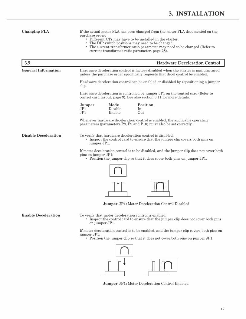
General Information Hardware deceleration control is factory disabled when the starter is manufacturedunless the purchase order specifically requests that decel control be enabled.
Hardware deceleration control can be enabled or disabled by repositioning a jumperclip.
Hardware deceleration is controlled by jumper JP1 on the control card (Refer tocontrol card layout, page 9). See also section 3.11 for more details.
Jumper Mode PositionJP1 Disable InJP1 Enable Out
Whenever hardware deceleration control is enabled, the applicable operatingparameters (parameters P8, P9 and P10) must also be set correctly.
Disable Deceleration To verify that hardware deceleration control is disabled:• Inspect the control card to ensure that the jumper clip covers both pins on
jumper JP1.
If motor deceleration control is to be disabled, and the jumper clip does not cover bothpins on jumper JP1:
• Position the jumper clip so that it does cover both pins on jumper JP1.
Jumper JP1: Motor Deceleration Control Disabled
Enable Deceleration To verify that motor deceleration control is enabled:• Inspect the control card to ensure that the jumper clip does not cover both pins
on jumper JP1.
If motor deceleration control is to be enabled, and the jumper clip covers both pins onjumper JP1:
• Position the jumper clip so that it does not cover both pins on jumper JP1.
Jumper JP1: Motor Deceleration Control Enabled
17
3. INSTALLATION

3.6 Variable Voltage or Current Input
General The starter can be also used as a voltage or current controller which will provide avoltage or current output proportional to an analog input signal. Parameter P22 -Starter Mode is used to set the operating mode (see page 30). The control options areas follows;
• Potentiometer voltage control using 1k� to 10k� potentiometer.• 4 to 20mA external input.• 0 to 5VDC external input.• 0 to 10VDC external input.
Changing from the minimum to maximum input will vary the output voltage from 0 toline voltage or current from 0 to the programmed motor FLA value.
NOTE: The analog voltage input is not an isolated input. The installation of anisolation board in the soft-starter cabinet is recommended for mixed wire runs(�120VAC in same wire-way) or for wire lengths over 20 feet.
Jumper Configuration Jumpers JP2, JP3, and JP4 are used to set the starter for the type of input controlthat is used. The jumpers are configured as follows;
Setting JP2 JP3 JP4
4-20mA External Control In 1-2 x
0-5VDC External Control Out 2-3 1-2
0-10VDC External Control Out 2-3 2-3
Potentiometer Control In Out x
x = not relevant to setting
Connections Terminal block TB2 is used for the variable voltage control input. The followingconnection configurations can be used for the variable voltage control;
3.7 Door Mounted Display
General The starter can be supplied with an optional door mounted display. The door mounteddisplay and buttons provides most of the functions of the circuit mounted display andbuttons plus it adds an overload reset pushbutton and 4 indicator LEDs for fault,up-to-speed, motor power, and overload. The door mounted display can also be fieldinstalled at a later date.
Door Template Door cut-out detail is provided on page 43 in this manual.
18
3. INSTALLATION

Interface Card The door mounted display requires the addition of an adapter card to the control card.The door mounted display is then connected to the circuit card with a 10 conductorribbon cable.
Door Display The door mounted display performs the same functions as the display and buttons onthe circuit card. In addition, the door mounted display adds an overload reset pushbutton. The door mounted display does not support the combination button pressesthat the circuit board display does.
19
3. INSTALLATION
CABLE CLAMPRIBBON CABLE
FRONT VIEW
SIDE VIEW
DMS REMOTE DISPLAYMOUNTING BRACKET
CON1 CONNECTORFROM DMS REMOTEDISPLAY INTERFACE BOARD
10 PIN ADAPTER
OVERLOADENTER
MOTOR
POW
ER
UP
TO
SPEED
FAULT
OVERLOAD
RESET
P
BENSHAW
DMS REMOTE DISPLAYMOUNTING PLATE
REMOVEABLE DMS REMOTEDISPLAY UNIT
MOUNTING HOLES
BACK VIEWDMS REMOTE DISPLAYMOUNTING BRACKETBACK VIEW
RIBBON CABLE
CABLE CLAMP
RIGHT HAND HINGELEFT HAND HINGE
RIGHT HAND HINGE
10 PIN ADAPTER
LEFT HAND HINGE
SIDE VIEW
CON1 CONNECTORFROM DMS REMOTE
DISPLAY INTERFACE BOARD
END VIEW
NYLON STANDOFF3 PLACES
THERMAL RESET
DMS REMOTE DISPLAYINTERFACE BOARDBIPC-300018
TOP VIEW
DMS REMOTE DISPLAYINTERFACE BOARD
BIPC-300018
DOWNPARAMETER UP ENTER DIAGNOSTIC UART
DMS BOARDBIPCDMS
CON1
SW2SW1 SW3 SW4
RXTXJ1
TB
3
N1O C2
BIPC-300018- -
S/N
2
K6
RIBBON CABLE
CON2
RIGHT HAND HINGE
RIGHT HAND HINGE
LEFT HAND HINGE
LEFT HAND HINGE
END VIEW
DMS REMOTE DISPLAYINTERFACE BOARD
BIPC-300018
NYLON STANDOFF3 PLACES
CON1
DMS REMOTE DISPLAYINTERFACE BOARDBIPC-300018
TOP VIEW
THERMAL RESETDOWN
SW2
PARAMETER
SW1
UP ENTER
SW3 SW4
DIAGNOSTIC UART
TB
3
ON
1 C2BIPC-300018- -
J1TX RX
2
S/N
DMS BOARDBIPCDMS
K6
RIBBON CABLE
CON2

4.1 General Operating Parameter Information
General Information To ensure the safe and reliable operation of the starter, it is essential that theoperating parameters are correctly programmed before the motor is started.
The operating parameters can be displayed on the control card’s three character LEDdisplay (or the optional door mounted display). The push buttons underneath thedisplay are used to verify and adjust the parameter values (Refer to the control carddiagram, page 9).
The operating parameters can be adjusted for specific applications. Once theoperating parameters are set for a specific application, document them on theoperating parameters chart (last page of this manual) for future reference.
Parameter Values Parameter values are displayed on the LED display on the control card. The pushbuttons underneath the display are used to verify and adjust the parameter value(Refer to the control card diagram, page 9).
NOTE: When verifying or adjusting the parameter value, if the push buttons are notused for 60 seconds, whatever is being displayed will disappear and the normaloperating message will reappear. Any parameter that was changed without pressingthe Enter button will not be stored.
Parameter values can be changed when the motor is running, but changing aparameter could affect the motor’s operation or cause a fault condition.
Incorrect Parameter Values If the decimal point furthermost to the right on the red LED display is blinking, thestarter has detected a condition which may prevent operation. To identify the pendingfault:
At the normal LED display:• Press the Enter button. The pending (fault if start is pressed) fault code will
appear.• Refer to fault codes, page 36, to determine the incorrect parameter value.• Press the Enter button to return to the normal LED display.
Parameter Verification To verify the parameter value in question:• Ensure the starter is powered-on.• Press the Parameter (P) button.• Press the Up or Down buttons until the parameter number is displayed.• Press the Enter button. The programmed parameter value will appear.• Verify that the displayed parameter value is the same as the desired value.
Parameter Adjustment If the displayed parameter value is correct then it does not need to be adjusted. If thedisplayed parameter value is not correct then it must be changed.
To adjust the parameter value:• Select the parameter value on the control card’s LED display (see parameter
verification above).• Press the applicable Up or Down button until the correct parameter value
appears.• Press the Enter button to program the new parameter value.
If the Enter button is not pressed within 60 seconds after the new parameter value isentered:
• The new parameter value will disappear. It will not be programmed.• The normal operating message will reappear.• The previously programmed parameter value will remain programmed.
NOTE: If it is desired not to set the new value, press the Parameter (P) button. Thiswill abort the parameter edit and return to the parameter menu. Press Parameter (P)again to return to the normal display.
20
4. OPERATING PARAMETERS
4.2 P1 - Motor Full Load Amps
Parameter Description The motor full load amps parameter must be the same value as the motor’s FLA. (Themotor’s FLA is stamped on the motor nameplate). See page 16 for the possible settingswith the CTs supplied and the different burden switch settings.
NOTE: If more than one motor is to be started by the same starter, the motor FLAparameter must be the sum of all of the individual motor full load amp ratings.
NOTE: At or above 1000 Amps, the actual FLA is displayed by the starter in units ofthousands of Amps (e.g., 1.00 = 1000A, 1.01 = 1010A, 1.20 = 1200A).
Parameter Values The motor FLA parameter values range from 1 Amp through 1200 Amps.• Parameter values from 1 Amp through 999 Amps are set in 1 Amp increments.• Parameter values from 1000 Amps through 1200 Amps are set in 10 Amp
increments.
NOTE: In current controller mode (Cn3) this parameter represents the 100% currentlevel.
Parameter Default The motor FLA parameter’s default value is 1 Amp.
4.3 P2 - Overload Multiplier
Parameter Description The motor overload multiplier parameter should be set to the same value as themotor’s service factor. (The motor’s service factor is stamped on the motor nameplate).
The motor overload multiplier affects the overload relay maximum trippingpercentage as indicated in the NEC article 430. The overload multiplier indicates themaximum continuous running motor current over that marked on the motornameplate. For example, a motor with a marked FLA of 126 amps and a 1.15 overloadmultiplier may be run at 126 x 1.15 = 150 amps continuous.
NOTE: P2 is not used in any of the controller modes.
Parameter Values The motor overload multiplier parameter values are:• 1.00• 1.05• 1.10• 1.15• 1.20• 1.25• 1.30• 1.35• 1.40
Parameter Default The motor overload multiplier parameter’s default value is 1.15.
21
4. OPERATING PARAMETERS

4.4 P3 - Motor Thermal Overload
Parameter Description The motor thermal overload parameter helps protect the motor from overheatingwithin the standard NEMA classification.
NOTE: When the motor thermal overload parameter is set to OFF, the starter doesnot provide motor thermal overload protection. In this case, an external means ofmotor protection must be provided.
NOTE: Verify the selected overload class is acceptable. Contact the motormanufacturer for stall time damage curves.
From a cold motor start:• A class 10 overload will trip the starter and activate the fault relay in 10
seconds at 600% of the Motor FLA.• A class 20 overload will trip the starter and activate the fault relay in 20
seconds at 600% of the Motor FLA.• A class 30 overload will trip the starter and activate the fault relay in 30
seconds at 600% of the Motor FLA.
Parameter Values The motor thermal overload parameter values are:• Class 10• Class 20• Class 30• Off
Parameter Default The motor thermal overload parameter’s default value is class 10.
4.5 P4 - Initial Motor Starting Current
Parameter Description The initial motor starting current parameter is the percentage of the full load amps(P1) initially delivered to the motor when it is started. It should be set to a level thatallows the motor to begin accelerating as soon as a start is commanded.
If the motor does not begin to accelerate immediately after a start is commanded, thenincrease this parameter value. If the motor begins accelerating too quickly when astart is commanded, decrease this parameter value.
NOTE: P4 is not used in any of the controller modes.
Parameter Values The initial motor starting current parameter values range from 50% to 400%.Parameter values are set in 5% increments (i.e., 55%, 60%, 65%).
Parameter Default The initial motor starting current parameter’s default value is 100%.
22
4. OPERATING PARAMETERS

4.6 P5 - Maximum Motor Starting Current
Parameter Description The maximum motor starting current parameter limits the amount of currentdelivered to the motor during motor start-up and normal motor operation. Its value isexpressed as a percentage of the full load amps (P1) setting.
During motor start-up the motor current may not reach this setting. The maximummotor starting current setting is reached only when it is required to start the load.
In all cases, the maximum motor starting current must be set high enough to enablethe motor to accelerate to full speed under all load conditions.
NOTE: The motor’s speed should be monitored during start-up to ensure that fullspeed is achieved with the set maximum motor starting current value.
The maximum motor starting current value may need to be reduced for constantcurrent applications in order to limit the motor’s peak starting current. If themaximum motor starting current is set below the initial current value, the starter willperform a constant current start, holding the current at the maximum motor startingcurrent parameter value.
NOTE: P5 is not used in any of the controller modes.
NOTE: Once the motor is up to speed, the starter does not attempt to regulatecurrent.
Parameter Values The maximum motor starting current parameter values range from 200% through600%. Parameter values are set in 5% increments (i.e., 205%, 210%, 215%).
Parameter Default The maximum motor starting current parameter’s default value is 600%.
4.7 P6 - Motor Ramp Time
Parameter Description The motor ramp time parameter sets the amount of time (in seconds) that the starterwill smoothly ramp from the selected initial motor current parameter value to theselected maximum motor current parameter value.
For many applications, the motor and the driven load do not require the set currentlevel or ramp time to achieve full speed. If the motor’s acceleration during start-up isacceptable, then no further adjustments are necessary.
NOTE: If the motor accelerates too quickly, increase ramp time. If the motoraccelerates too slowly, decrease ramp time.
NOTE: P6 is not used in any of the controller modes.
NOTE: If a motor ramp time parameter value of 0 seconds is selected with amaximum motor current parameter value of 600%, the starter will act as a solid statecontactor and the motor will start instantaneously without ramping. This is similar toa full voltage or across-the-line start.
Parameter Values The motor ramp time parameter values range from 0 seconds through 120 seconds.Parameter values are set in 1 second increments.
Parameter Default The motor ramp time parameter’s default value is 15 seconds.
23
4. OPERATING PARAMETERS

4.8 P7 - Motor Stall Time
Parameter Description The motor stall time parameter sets the amount of time (in seconds), from thebeginning of the ramp time that the starter will give the motor to achieve its fulloperating speed before the starter disconnects the motor’s current and displays a faultmessage.
NOTE: P7 is not used in any of the controller modes.
NOTE: Stall time must be greater than ramp time or a stall will always occur.
Parameter Values The motor stall time parameter values range from 0 seconds through 240 seconds.Parameter values are set in 1 second increments.
Parameter Default The motor stall time parameter’s default value is 30 seconds.
4.9 P8 - Deceleration Level 1
Parameter Description The motor deceleration level 1 parameter is the initial percentage of line voltagedelivered to the motor after a Stop command has been received.
NOTE: The motor deceleration level 1 parameter is not functional when the motordeceleration control jumper JP1 on the control card is in the disabled position or if themotor deceleration time (P10) parameter is set to OFF (Refer to motor decelerationtime parameter, page 25).
If the motor initially surges when a stop is commanded, decrease this parametervalue. If the motor has a large, sudden drop in speed when a stop is commanded,increase this parameter value.
NOTE: P8 is not used in any of the controller modes.
Parameter Values The motor deceleration level 1 parameter values range from 0% through 100%.Parameter values are set in 1% increments.
Parameter Default The motor deceleration level 1 parameter’s default value is 40%.
24
4. OPERATING PARAMETERS

4.10 P9 - Deceleration Level 2
Parameter Description The motor deceleration level 2 parameter is the final percentage of line voltagedelivered to the motor after a Stop command has been received, and the timedetermined by the motor deceleration time (P10) parameter has expired.
The motor deceleration level 2 parameter is not functional if the motor decelerationcontrol jumper JP1 on the control card is in the disabled position or if the motordeceleration time (P10) parameter is set to OFF (Refer to motor deceleration timeparameter, page 25).
If the motor is still rotating when the deceleration time has expired, decrease thisparameter value. If the motor stops rotating before the deceleration time has expired,increase this parameter value.
NOTE: P9 is not used in any of the controller modes.
Parameter Values The motor deceleration level 2 parameter values range from 0% through 100%.Parameter values are set in 1% increments.
NOTE: The motor deceleration level 2 parameter’s value must be less than the motordeceleration level 1 parameter’s value. If the deceleration level 2 parameter is sethigher than the deceleration level 1 parameter, the starter will swap the decelerationlevel 1 and deceleration level 2 settings when decel is commanded.
Parameter Default The motor deceleration level 2 parameter’s default value is 10%.
4.11 P10 - Deceleration Time
Parameter Description The motor deceleration time parameter sets the deceleration time from motordeceleration level 1 to motor deceleration level 2. Deceleration time is the amount oftime during which the starter will gradually reduce the amount of line voltage beingdelivered to the motor (after a Stop command has been received).
The motor deceleration time parameter is not functional when the motor decelerationcontrol jumper JP1 on the control card is in the disabled position.
When this parameter is set to any value other than OFF, the motor deceleration Level1 and motor deceleration Level 2 parameters must be programmed.
When the motor deceleration time parameter is set to OFF, the motor decelerationlevel 1 and motor deceleration level 2 parameters are disabled.
If the motor is still rotating when the deceleration time expires, increase thedeceleration time. If the motor stops rotating before the deceleration time expires,decrease the deceleration time.
NOTE: If the motor deceleration time parameter is set to OFF, the motor’sdeceleration is not controlled by the starter. If the motor needs to be stopped fasterthan the time it takes to coast to a stop, the deceleration control will not help.
NOTE: P10 is not used in any of the controller modes.
NOTE: If deceleration jumper JP1 is in place and deceleration time is programmed,the deceleration will not operate. The deceleration timer will block a restart attemptuntil it has timed out. This can operate as a blocked restart timer for up to 1 minute.This is useful for reversing starters or dual starters.
Parameter Values The motor deceleration time parameter values range from OFF to 60 seconds.Parameter values are set in 1 second increments.
Parameter Default The motor deceleration time parameter’s default value is OFF.
25
4. OPERATING PARAMETERS

4.12 P11 - Overcurrent Trip Level
Parameter Description The overcurrent trip level parameter sets the high current level trip point as apercentage of motor full load amps parameter P1. The overcurrent trip levelparameter takes effect after the motor is up to speed. This protection feature is alsoreferred to as mechanical jam protection.
NOTE: The overcurrent trip level parameter is not operational if the overcurrent triptime parameter (P12) is set of OFF.
Parameter Values The overcurrent trip level parameter values range from 50% through 400%.Parameter values are set in 5% increments.
Parameter Default The overcurrent trip level parameter’s default value is 50%.
4.13 P12 - Overcurrent Trip Time
Parameter Description The overcurrent trip time parameter sets the length of time that the load current cancontinuously exceed the overcurrent trip level before a fault is generated.
Parameter Values The overcurrent trip time parameter values range from OFF through 15 seconds.Parameter values are set in one second increments.
axx indicates the fault will auto-restart after tripping in xx seconds.txx indicates the fault will require manual reset after tripping in xx seconds.
Parameter Default The overcurrent trip time parameter’s default value is OFF.
Parameter Order a15
a14
.
.
.a02
a01
OFF
t15
t14
.
.
.t02
t01
4.14 P13 - Undercurrent Trip Level
Parameter Description The undercurrent trip level parameter sets the low current level trip point as apercentage of motor full load amps parameter (P1). The undercurrent trip levelparameter takes effect after the motor is up to speed.
NOTE: The undercurrent trip level parameter is disabled if the undercurrent triptime parameter P14 is set to OFF.
Parameter Values The undercurrent trip level parameter values range from 25% through 100%.Parameter values are set in 5% increments.
Parameter Default The undercurrent trip level parameter’s default value is 25%.
26
4. OPERATING PARAMETERS
4.15 P14 - Undercurrent Trip Time
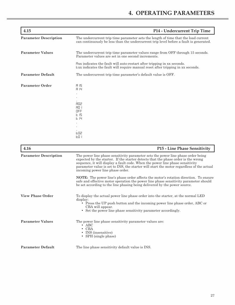
Parameter Description The undercurrent trip time parameter sets the length of time that the load currentcan continuously be less than the undercurrent trip level before a fault is generated.
Parameter Values The undercurrent trip time parameter values range from OFF through 15 seconds.Parameter values are set in one second increments.
axx indicates the fault will auto-restart after tripping in xx seconds.txx indicates the fault will require manual reset after tripping in xx seconds.
Parameter Default The undercurrent trip time parameter’s default value is OFF.
Parameter Order a15
a14
.
.
.a02
a01
OFF
t15
t14
.
.
.t02
t01
4.16 P15 - Line Phase Sensitivity
Parameter Description The power line phase sensitivity parameter sets the power line phase order beingexpected by the starter. If the starter detects that the phase order is the wrongsequence, it will display a fault code. When the power line phase sensitivityparameter value is set to INS, the starter will start the motor regardless of the actualincoming power line phase order.
NOTE: The power line’s phase order affects the motor’s rotation direction. To ensuresafe and effective motor operation the power line phase sensitivity parameter shouldbe set according to the line phasing being delivered by the power source.
View Phase Order To display the actual power line phase order into the starter, at the normal LEDdisplay:
• Press the UP push button and the incoming power line phase order, ABC orCBA will appear.
• Set the power line phase sensitivity parameter accordingly.
Parameter Values The power line phase sensitivity parameter values are:• ABC• CBA• INS (insensitive)• SPH (single phase)
Parameter Default The line phase sensitivity default value is INS.
27
4. OPERATING PARAMETERS

4.17 P16 - Motor Current Imbalance
Parameter Description The motor current imbalance parameter sets the percentage of acceptable differencebetween the line-to-line currents. If the difference exceeds the set percentage for morethan 10 seconds, the starter will issue a fault message and remove power from themotor.
NOTE: Current imbalances will be ignored if the average line current is < 40%.
Parameter Values The motor current imbalance parameter values range from 5% through 40%.Parameter values are set in 5% increments.
Parameter Default The motor current imbalance parameter’s default value is 20%.
4.18 P17 - Current Transformer Ratio
Parameter Description The current transformer ratio parameter is factory set to match the currenttransformers (CTs) installed in the package. The CTs are used to accurately measurethe line current being delivered to the motor.
NOTE: If the CTs installed in the package are changed to CTs with a different ratio,the current transformer ratio parameter must be changed. The CTs are custommanufactured by Benshaw. The applicable CT Ratio is stamped on the CT.
Parameter Values The current transformer ratio parameter values are:• 72 (72:1) - Wire passes through 288:1 CT four (4) times.• 96 (96:1) - Wire passes through 288:1 CT three (3) times.• 144 (144:1) - Wire passes through 288:1 CT two (2) times.• 288 (288:1)• 864 (864:1)• 2.64 (2640:1)• 2.88 (2880:1)• 5.76 (5760:1)
Parameter Default The current transformer ratio parameter’s default value is 288.
4.19 P18 - Meter Mode
Parameter Description The meter mode parameter sets what the display on the starter will indicate. Thestarter has the capability of displaying different metered values on the displaydepending on this parameter setting.
NOTE: When this parameter is set from 0 to 5, the user must press the Enterpushbutton, while the starter is running, to view the selected meter function.
Parameter Values The meter mode parameter values are:• 0 - Average phase current.• 1 - L1 phase current.• 2 - L2 phase current.• 3 - L3 phase current.• 4 - Maximum phase current.• 5 - Current imbalance level.• 10 - Automatically display average phase current when started.• 11 - Automatically display L1 phase current when started.• 12 - Automatically display L2 phase current when started.• 13 - Automatically display L3 phase current when started.• 14 - Automatically display Maximum phase current when started.• 15 - Automatically display current imbalance level when started.
Parameter Default The meter mode parameter’s default value is 10.
28
4. OPERATING PARAMETERS

4.20 P19 - Meter Dwell Time
Parameter Description The meter dwell time parameter sets the time between meter updates. Each time themeter updates, the starter will display the highest value reached since the lastupdate. This feature can be used to view the peak currents reached during starting orduring a repetitive process.
Parameter Values The meter dwell time parameter values are off or 2 to 30 seconds. The meter dwelltime is set in 2 second intervals.
Parameter Default The meter dwell time parameter’s default value is 2 seconds.
4.21 P20 - Passcode
Parameter Description The passcode feature allows the user to protect the parameters from unauthorizedmodifications.
When entering the parameter, if the display momentarily shows dis:• Parameter protection is disabled and parameters can be modified.• Use the Up and Down buttons to select a passcode.• When a passcode is entered, the display will show ena and the starter
parameters are protected.
When entering the parameter, if the P20 display momentarily shows ena:• Parameter protection is enabled and the starter parameters cannot be modified.• Use the Up and Down buttons to select the previously set passcode.• When correct passcode is selected and the Enter button is pressed, the display
will show dis and the starter parameters can be modified.• Once the proper passcode is entered and the display shows dis, the passcode
can be reset back to Off to disable passcode protection.
If a parameter change is attempted while the parameters are passcode protected, thedisplay will flash no and the parameter will not be changed.
Parameter Values The passcode parameter can be set to Off (disabled) or from 1 to 255.
Parameter Default The passcode parameter’s default value is Off (disabled).
4.22 P21 - 500% Current Kick Time
Parameter Description The 500% current kick time allows the user to program a 500% current override at thebeginning of the current ramp profile. This 500% current kick will be provided to themotor for the time programmed. The 500% current kick can be used to start a motorwith a very high break-away torque requirement.
NOTE: If current transformers are not used, the unit will do a full voltage kick in Cn1or Cn2 mode.
Parameter Values The 500% current kick time parameter can be set to Off or from 0.1 to 5.0 seconds in0.1 second intervals.
Parameter Default The 500% current kick time parameter’s default value is Off (disabled).
29
4. OPERATING PARAMETERS

4.23 P22 - Starter Mode
Parameter Description The starter mode parameter allows the user to set the operating mode of the starter.The starter can be operated in the closed loop current ramp motor starting mode or inan open loop voltage controller mode. The current ramp is used for standard motorstarting. The voltage controller is used for heater control or other similar applications.
See page 18 for a description of the control methods, hardware settings, and wiring.
When the starter mode is changed, the circuit card must be fully reset by pressing theParameter and Enter buttons simultaneously causing a circuit card reset.
NOTE: The starter will fault on F60 if < 4mA is read on TB2 in any of the 4-20mAmodes. If start is not commanded, a pending fault will be indicated.
Parameter Values The starter mode parameter can be set to• nor - Current ramp operating mode.• Cn1 - 4-20mA open loop voltage.• Cn2 - 0-5V/0-10V or potentiometer open loop voltage.• Cn3 - 4-20mA closed loop 0-100% FLA current mode.• Consult factory for tachometer feedback.
Parameter Default The starter mode parameter’s default value is nor.
30
4. OPERATING PARAMETERS

5.1 Pushbutton Functions
General Information The pushbuttons on the control card under the 7-segment display perform a numberof different functions.
Parameter Pushbutton The Parameter (P) pushbutton performs the following functions:• While in normal display mode:
- Enter parameter menu and exit.- Reset the CPU when pressed in conjunction with the Up pushbutton.
• While in parameter editing mode:- Abort editing of a parameter and return to parameter menu.
Down Pushbutton The Down pushbutton performs the following functions:• While in normal display mode:
- Toggle display of overload content.- Perform an emergency reset if pressed in conjunction with the Enter
pushbutton while OLL is displayed (card display only).• While in parameter selecting mode (Pxx on display):
- Move to previous parameter.• While in parameter editing mode:
- Decrease parameter value.
Up Pushbutton The Up pushbutton performs the following functions:• While in normal display mode:
- Toggle display of incoming line phase.- Reset the CPU when pressed in conjunction with the Parameter
pushbutton.• While in parameter selecting mode (Pxx on display):
- Move to next parameter.• While in parameter editing mode:
- Increase parameter value.
Enter Pushbutton The Enter pushbutton performs the following functions:• While in normal display mode:
- Display pending fault code if pressed when starter is stopped and theright dot is flashing.
- Perform an emergency reset if pressed in conjunction with the Downpushbutton while oll is displayed (card display only).
- Perform a thermal reset when olt is displayed.- Toggle the meter display when the starter is running.
• While in parameter selecting mode (Pxx on display):- Enter parameter editing mode.
• While in parameter editing mode:- Save displayed value and return to parameter selecting mode.
Overload Reset The overload reset performs the following functions (remote door display only).• While olt is displayed on the 7-segment display:
- Resets the thermal overload and allows the motor to be started.
31
5. OPERATING PROCEDURES

5.2 Starting The Motor
General Information For safe and reliable operation of the starter and the motor ensure:• All of the starting the motor procedures are conducted by a trained technician.• The starter has the correct voltage and current rating for the motor.• Any power factor correction (PFC) capacitors are installed on the power source
side of the starter and not on the motor side.• The starter has been installed correctly (Refer to Installation Procedures, page
13).• The operating parameters have been verified (Refer to Parameters, page 20).• The motor and its load are safe and ready to be started.• No personnel or equipment are near the motor.
CAUTION: Hazardous voltages may exist at the motor when power is applied to theterminals of the starter even if the starter is in the OFF state.
Starting the Motor As the motor is being started, it may be necessary to adjust the following parametersin order to achieve optimal motor performance and protection:
• Motor thermal overload class P3.• Initial motor current parameter P4.• Maximum motor current parameter P5.• Ramp time parameter P6.• Motor deceleration time parameter P10.• Power line phase sensitivity parameter P15.
When initially starting the motor, briefly initiate the Start command and then theStop command. Observe the motor to ensure:
• It begins to rotate slowly as soon as it receives the start command.• It rotates in the correct direction.
It the motor does not rotate:• Increase the initial motor current parameter (P4).• If the motor will not rotate, refer to the Starter Diagnostics on page 38.
If the motor rotates in the wrong direction:• LOCK OUT ALL POWER SOURCE(S).• Switch any two of the power or motor cable connections.• Repeat the start-stop sequence to ensure correct rotation.
If the motor begins to rotate in the correct direction (after an initial start and stopcommand).
• Apply a Start command.
As the motor is accelerating:• Observe the motor to ensure that it smoothly accelerates to full speed.• acc or the meter function is displayed on the control card LED display indicates
that the motor is accelerating.
When the motor achieves full operating speed:• uts or the meter function is displayed on the LED display on the control card.• The up to speed relay will energize.
When the starter is operating and the ramp time has expired:• run or the meter function is displayed on the LED display on the control card.
NOTE: If any other operating message is displayed, refer to Operating Messages,page 35. If a fault code is displayed, refer to Fault Codes, page 36.
Running Checks Measure the AC voltage between:• L1 terminal and T1 terminal.• L2 terminal and T2 terminal.• L3 terminal and T3 terminal.
32
5. OPERATING PROCEDURES

Ensure that each voltage measurement is less than 2 VAC.
Other Checks:• Measure the current on the motor cables to verify that the current on the motor
cables is balanced and each line is within acceptable amperage limits.• Measure the motor shaft speed with a tachometer to confirm that the motor is
operating at rated speed.
CAUTION: Hazardous voltages exist at the starter terminals. Use extremecaution when measuring the voltages.
Thermal Overload The thermal overload provides motor thermal protection. It is designed so that thepercentage of overload will follow the thermal content of the motor. The starter usesthe current to model the motor temperature. The starter also models the running heatin the motor by lowering the allowable overload time depending on the motor load (seepage 7 for the overload curves).
The thermal overload will settle at the following thermal content percentages,according to the motor load:
• 10% - When the motor current is between 0% and 50% of the FLA value.• 20% - When the motor current is between 50% and 75% of the FLA value.• 30% - When the motor current is between 75% and 100% of the FLA value.
Once the thermal overload has tripped, the starter will take the following times to cooldown, which are dependant on the class of the overload:
• Class 10 overload - 6 minutes• Class 20 overload - 12 minutes• Class 30 overload - 18 minutes
To ensure that the motor will not overheat during normal operations check the motorthermal overload content. At the normal LED display:
• Press the Down push button on the control card or remote door display.• The percentage of the motor’s total thermal capacity (i.e., the motor thermal
overload content) will appear on the red LED Display.• Ensure that the motor thermal capacity is not increasing past the hot running
value, as listed above, during normal operation. It will rise during starting andthen it should settle once the motor is up to speed.
• Press the Down push button on the control card or remote door display to returnto the normal LED display.
NOTE: If power to the control card is removed, all motor thermal overload contentinformation stored by the starter will be lost. Caution should always be used to ensurethat a thermally overloaded motor is not started as if it were a cold motor.
CAUTION: Except in emergencies, allow a thermally overloaded motor to cool beforerestarting it. This will prevent damaging the motor.
Resolving Overload Trips The National Electrical Code, article 430 Part C, allows for different overloadmultiplier factors depending on the motor and operating conditions.
NEC section 430-32 outlines the allowable overload multiplier (P2) for differentmotors as follows:
Motor Overload MultiplierService factor 1.15 or more 1.25Motor temp. rise 40°C or less 1.25All others 1.15
NEC section 430-34 permits further modifications if the overload multiplier (P2) is notsufficient to start the motor:
Motor Overload MultiplierService factor 1.15 or more 1.40Motor temp. rise 40°C or less 1.40All others 1.30
33
5. OPERATING PROCEDURES

Although the NEC doesn’t address the effect of the ambient temperature of the motorlocation, guidance can be derived by examining NEC limits. If the motor is operatingin an ambient temperature that is less than 40°C, then the overload multiplier can beincreased while still protecting the motor from exceeding it maximum designedtemperature. The following curve gives the ambient temperature vs the correctionfactor.
For example; If a motor operates at 0°C then a 1.36 correction factor could be appliedto the overload multiplier. This could give a theoretical overload multiplier of 1.36 x1.25 or 1.70. The highest legal value of overload multiplier is 1.40 so this could beused.
Overload Emergency Reset In emergency cases, when a thermally overloaded motor must be restarted before ithas cooled, and the power to the starter cannot be easily removed, the motor thermalcontent emergency reset can be used to delete motor thermal overload contentinformation from the starter so that the motor can be restarted.
To reset the motor thermal content in an emergency:• Press the Down button and Enter buttons simultaneously on the control card.• All motor thermal overload content information stored by the starter will be
deleted, and the motor may be restarted.
34
5. OPERATING PROCEDURES
1.00 1.500.500
100
40
60
80
20
Correction Factor
Tem
per
atu
re
Temperature vs Correction Factor

5.3 Operating Messages
General Information Operating messages are displayed on the three-character LED display on the controlcard. The LED display on the control card displays:
• Operating messages that indicate the status of the motor and/or starter.• Operating parameters that are programmed (Refer to page 20 for information on
operating parameters).• Fault codes that indicate a problem with the motor application or starter (Refer
to page 36 for information on fault codes).
Operating Messages The possible operating messages are as follows.
Message Meaning
no.l Line voltage is not present.
rdy Line voltage is present and the starter is ready.
acc Motor is accelerating after a start command has been received.
uts The motor has achieved full speed.
run Motor is operating at full speed, and ramp time is expired.
dCl A Stop command was received and the motor is deceleratingwith the set deceleration profile.
Ol OL will alternately blink with the normal display on the LEDdisplay when motor thermal overload content has reached90% to 99% of its capacity.
Oll The motor thermal overload content has reached 100%, andthe motor has been stopped. The motor cannot be restarted untilthe overloaded motor has cooled and OLt is displayed.
Olt The motor thermal overload content has been reduced to 60%or less, and the motor may be restarted.
ena Passcode protection is enabled.
dis Passcode protection is disabled.
oxx xx = overload thermal content in percentage. Press the Downbutton to toggle to this display.
cxx xx = pending fault
Fxx xx = fault code
no Attempted to change a passcode protected parameter.
. . . Three decimal places blink when remote display is active.
axx Automatically reset over/undercurrent fault after tripping in xxseconds.
txx Manual reset over/undercurrent fault after tripping in xx seconds.
35
5. OPERATING PROCEDURES

5.4 Fault Codes
General Information Fault codes will be displayed on the red, three-character LED display. Fault Codesindicate a problem with the starter or motor application.
Fault Reset To recover from a fault, perform a computer reset by pressing Parameter & Upbuttons simultaneously on the circuit board or by cycling the power to the controlcard.
Code Fault Possible Solutions
F1 Power line phase sensitivity parameter set to ABC for CBAline sequence.
Exchange any two incoming line connections or change thephase sensitivity parameter.
F2 Power line phase sensitivity parameter set to CBA for ABCline sequence.
Exchange any two incoming line connections or change thephase sensitivity parameter.
F3 System power is not three phase. Check for missing line or reset starter to single phaseoperation.
F4 System power is not single phase. Ground unused phase, check for missing line power, orreset starter to three phase operation.
F5 Line frequency is less then 25hz. Check the power line frequency to the starter.
Correct the power source.
F6 Line frequency is greater then 75hz. Check the power line frequency to the starter.
Correct the power source.
F23 Line current imbalance is greater than set currentimbalance level.
Correct the cause of the motor current imbalance orincrease the motor current imbalance parameter P16.
F24 Line currents became very unbalanced while the motorwas running.
Check line currents going through the currenttransformers for an unbalanced condition. Check thestarter for possible shorted SCRs
F29 Operating parameters have been lost. Load the default parameters. Verify all operatingparameters are set correctly.
F30 Three phase default parameters have been loaded. This is only a message, not a fault.
F31 Single phase default parameters have been loaded. This is only a message, not a fault.
F52 A Motor current greater than 12.5% was detected while themotor was stopped.
Check starter for shorted SCR’s or other problems whichwould lead to a current while stopped.
F54 An undercurrent trip has occurred. Check the undercurrent trip level parameter P13. Checkthe application for the undercurrent problem.
F55 An overcurrent trip has occurred. Check the overcurrent trip level parameter P11. Check theapplication for the overcurrent problem.
F60 No control Check if there is < 4mA on TB2 when in 4-20mA controllermode.
F70 Control power is too low. Correct low power condition.
F71 Motor current transformer scaling switches were changedwhile the motor was running.
Set switches to the correct positions. Changing theswitches while the motor is running may cause damage tothe switches.
F74 The motor stalled while accelerating. Verify that the parameters are set to allow proper motoracceleration (P1, P4, P5, P6, P7).
F75 External fault. Check for 120VAC input into TB1 terminals 15 and 16.
F77 Control card fault. Reset. Consult factory if fault persists.
F78 Control card fault. Reset. Consult factory if fault persists.
F90 Incorrect set-up. Full-load amps (P1), CT ratio (P17), or CT burden selectswitch set incorrectly.
F92 A shorted SCR was detected during acceleration. Check SCRs.
F97 Control card fault. Reset. Consult factory if fault persists.
F98 Line power was missing when Start command was given orwhile starter was operating the motor.
Check the incoming line power connections. Verify anyprotection or control devices are connected correctly andare operational.
F99 Load current very high. Check load for shorts and other faults that would cause ahigh current condition.
36
5. OPERATING PROCEDURES

5.5 Preventative Maintenance
General Information Preventive maintenance performed on a regular basis will help ensure that the startercontinues to operate reliably and safely. The frequency of preventive maintenancedepends upon the type of maintenance and the installation site’s environment.
NOTE: Preventive maintenance should always be performed by a trained technician.
Preventive Maintenance During Commissioning;• Torque all power connections during commissioning. This includes pre-wired
equipment.• Check all of the control wiring in the package for loose connections.
For the first month after the starter has been put in operation;• Re-torque all power connections every two weeks. This includes pre-wired
equipment.• Inspect the cooling fans after two weeks to ensure proper operation.
After the first month of operation;• Re-torque all power connections every year.• Clean any accumulated dust from the starter using a clean source of compressed
air.• Inspect the cooling fans every three months to ensure proper operation.• Clean or replace any air vent filters on the starter every three months.
NOTE: If mechanical vibrations are present at the installation site, inspect theconnections more frequently.
37
5. OPERATING PROCEDURES

5.6 Starter Diagnostics
General Information The diagnostic flowcharts on the following pages can be used to help locate the sourceof a problem with an operational motor. The numbered steps on the flowchartscorrespond to notes on the page after the flowcharts.
38
5. OPERATING PROCEDURES
Low or Missing
Line?
Phase Order
Fault
Thermal Trip?
InterlockOpen?
Wiring OK?High
Ambient?
In-Line OK?
Circuit
Breaker OK?
Fuses OK?
Does Problem
Still Exist
Bad Air
Circulation?
Motor
Overloaded?
Wiring OK?
Swap Any2 Power
Leads
Correct and
Wait to Cool
Replace
Control Card
Lower Motor
Load
Correct and
Wait to Cool
Correct
Wiring
Return To
Service
Replace
Circuit
Breaker
ReplaceFuses
Correct
Inline Fault
Correct
InterlockState
Correct PowerSource
Problem
Correct
Wiring
No
Yes
Yes
No
No
No
No
No
No
No
Yes
Yes
Yes
No
NoYes
Yes No
NoYes
Yes Yes
Yes
Yes
Yes
No
Return To
Service
3
4
Start
5
6
7 8
9
10
7
1
2
Goto Page 2

39
5. OPERATING PROCEDURES
Current
Imbalance Fault?
Wiring Good?
SCRs OK?
Motor
Winding Short?
All Gate
Pulses Present?
Replace
Control Card
Return to
Normal
Operation
Yes
Yes Yes
No
Yes Yes
No Yes
Yes
No
No
No
Yes
Yes
No
No
No
No
Motor Problem?
Repair or
Replace Motor
Contact
Benshaw
For Assistance
Replace
Control Card
Check JumpersParameters
and CTs
Correct Wiring
Replace
Defective SCRs
Does Problem
Still Exist?
Contact
Benshaw
For Assistance
CT Burden
Switches Set
Correctly?
Fuses Blown or
Breaker Tripped?
Replace Fuse
or Reset Breaker
From Page 1
11
7
12
13
14
12
15

Flowchart Details:
1. Fuses Determine if power line fuses have been installed, and if they are operating properly.
2. Circuit Breaker Determine if the circuit breaker is off, or if it has tripped and disconnected the linefrom the starter.
3. Power Line Voltage Verify that line voltage is present, and is the correct voltage.
4. Phase Order Fault If Fault Codes F1 or F2 are displayed on the control card LED display, exchange anytwo incoming power line cable connections.
5. Heat sink Switch Investigate whether a heat sink thermal switch contact is open.
6. Safety Device Determine if a safety device attached to the starter is disabling the start command.
7. Wiring Connections Verify that the wiring connections are correct and the terminations are tighten.
8. Air Temperature Investigate whether the air temperature surrounding the heat sink is too hot.
9. Air Circulation Determine if the air flow around the heat sink fins is being restricted, or if a fan hasfailed.
10. Motor Overload Determine if the motor’s load is too large for the motor size.
11. Current Imbalance Fault If Fault Codes F23 or F24 are displayed on the control card LED display, diagnoseand correct the cause of the current imbalance, or adjust the current imbalanceparameter P16 (Refer to page 28 for information on adjusting the parameter).
12. Motor Winding Problem Conducting a megger test of the motor may identify if the loss of current occurs at themotor.
NOTE: To avoid damaging the starter, disconnect the starter from the motor beforeconducting the megger test.
13. SCRs This step may help determine if a problem exists with the SCRs. Using a multi-meteror similar device, measure the resistance between:
• L1 terminal and T1 terminal.• L2 terminal and T2 terminal.• L3 terminal and T3 terminal.
The resistance should be more than 50k ohms.
Measure the gate resistance between the white and red of each twisted pair (6 total).The gate resistance should be between 8 and 50 ohms.
CAUTION: Hazardous voltages exist at the starter terminals. LOCK OUT ALL OFTHE SOURCES OF STARTER POWER before measuring the resistance.
14. Gate Pulses This step may help determine if the control card is operating correctly. Check for agate firing voltage between 0.3 and 1.5 volts when the card is operating.
15. Motor Current Determine if the motor current signal scaling is correct (Refer to page 16 forinformation on motor current signal scaling).
40
5. OPERATING PROCEDURES

5.7 Default Settings
General Information As a programming convenience, the operating parameters can be reset to their defaultvalues at any time.
If fault code F29 appears on the LED display on the control card, the previouslyprogrammed operating parameters have been deleted.
If the majority of actual operating parameter settings were the default settings fromwhen the starter was manufactured, then the parameters can be automatically resetto their default values using the reset default settings procedure.
NOTE: Any of the operating parameter settings that were customer specified mustbe manually reprogrammed as detailed in chapter 5 of this manual.
Default Values The operating parameter default settings are:
Parameter Description Default Programmed
P1 Motor Full Load Amps 1 Amp __________
P2 Overload multiplier 1.15 __________
P3 Motor Thermal Overload Class 10 __________
P4 Initial Motor Starting Current 100% __________
P5 Max. Motor Starting Current 600% __________
P6 Motor Ramp Time 15 seconds __________
P7 Motor Stall Time 30 seconds __________
P8 Deceleration Level 1 40% __________
P9 Deceleration Level 2 10% __________
P10 Deceleration Time Off __________
P11 Overcurrent Trip Level 50% __________
P12 Overcurrent Trip Time Off __________
P13 Undercurrent Trip Level 25% __________
P14 Undercurrent Trip Time Off __________
P15 Line Phase Sensitivity ins* __________
P16 Motor Current Imbalance 20% __________
P17 Current Transformer Ratio 288 __________
P18 Meter Mode 10 __________
P19 Meter Dwell Time 2 seconds __________
P20 Passcode dis __________
P21 500% Current Kick Time Off __________
P22 Starter Mode nor __________
* Single phase power line phase sensitivity (P15) default setting is SPH.
41
5. OPERATING PROCEDURES

Reset Default Settings If there is a reason that the user wants to quickly reset the parameters back to thedefault settings, then the reset default settings procedure can be performed. This willreset all the parameters to the default settings listed above. The reset can also beperformed to clear a passcode that has been forgotten.
To automatically reset the operating parameter to the default settings:
Single PhaseWhile the power to the control card is off:
• Hold the Parameter push button and the Down push button on the control card.
While continuing to hold the Parameter and Down push buttons.• Restore power to the control card.• Continue to hold the Parameter and Down push buttons until F31 appears on
the LED display on the control card.
When F31 appears on the LED display:• Stop holding the push buttons.• Remove power from the control card.• Restore power to the control card.• Verify that the LED display on the control card displays either:
- rdy (ready)- no.l (no line)
Three PhaseWhile the power to the control card is off:
• Hold the Parameter push button on the control card.
While continuing to hold the Parameter push button.• Restore power to the control card.• Continue to hold the Parameter push button until F30 appears on the LED
display on the control card.
When F30 appears on the LED display:• Stop holding the push button.• Remove power from the control card.• Restore power to the control card.• Verify that the LED display on the control card displays either:
- rdy (ready)- no.l (no line)
NOTE: If the LED display is blank or anything else is displayed, refer to thetroubleshooting section, beginning on page 38.
When either rdy or no.l appears on the LED display, all operating parameter defaultsettings will have been restored. Operating parameters that had been previouslyadjusted for specific applications must be reprogrammed as detailed in chapter 5 ofthis manual.
42
5. OPERATING PROCEDURES

6.1 Door Mounted Display Template
Display Template This drawing provides detail for the door mounted display cut-out. Drawing may notprint to scale. The cut-out can be made with a Green Lee knockout punch. The twohalves of the required punch are numbered 60075 and 60076.
43
6. DISPLAY TEMPLATE
HOLE SIZE: Ø 3/16"
DMS DISPLAY CUT-OUT TEMPLATE
(ACTUAL SIZE)
5 11/32"
325/3
2"
2 43/64"
157/6
4"
25/8
"
5 3/8"
15/1
6"
2 11/16"

The Benshaw Inside Delta Starter
An example of a soft starter for a 6 lead delta-connected motor is shown in Figure 1, where the power poles of the softstarter are connected in series with the line. The starter draws line current (Ia, Ib, Ic ).
An inside delta soft starter is shown in Figure 2, where the power poles are connected in series with the stator windingsof a delta connected motor. The starter draws phase current (ia, ib, ic ).
In a delta-connected motor, the average phase current is less than the average line current by a factor of 1.73. Bycomparison of Figures 1 and 2, the most obvious advantage of the inside delta starter is the reduction of current seen bythe soft starter. The soft starter current rating is downsized by a factor of 1.73, which is a significant savings in cost andsize.
An inside delta soft starter can be considered for motors with more than 6 leads, including 12 lead dual voltage motors.Refer to Figures 3 and 4, which show inside delta soft starter connections for a 12-lead motor.Figures 1 through 4 give the NEMA and IEC nomenclature for motor terminal markings.
There are differences between a line connected soft starter as shown in Figure 1, and the inside delta connected softstarter as shown in Figure 2, which need to be understood. These differences are discussed below.
By observation of Figure 2, access to all six stator-winding terminals is required for an inside delta application. In theline connected soft starter of Figure 1, access to only three leads of the stator windings of the motor is required. For a12-lead motor, all 12 stator terminals must be accessible.
One failed SCR on any phase of the inside delta soft starter will result in a single-phase condition. A shunt circuitbreaker is recommended to protect against this case.
The software for an inside delta application is different than the software for a standard soft starter. The firing of theSCR’s is based on the line-to-line voltage crossings. A thirty-degree phase shift in the inside delta application requires anadjustment when Benshaw starts and stops firing the gates of the SCR’s.
If a circuit breaker is the only means to disconnect the soft starter and motor from the line, then one leg of the motorleads in the inside delta soft starter is always electrically live when the circuit breaker is closed. This requires caution toensure these leads of the motor are not exposed to personnel.
45
7. INSIDE DELTA OPTION

46
7. INSIDE DELTA OPTION
FIGURE 2: INSIDE DELTA SOFT STARTER FOR A 6 LEAD MOTOR.
V
VV
A
C B
IA
IB
CI
CI
CV
BV
VA
AI
IB
bi
ai
ci
FIGURE 1: EXAMPLE OF A SOFT STARTER FOR A 6 LEAD
DELTA CONNECTED MOTOR
CT2
CT3
L1
L3
L2
6 (W2)
3 (W1)
5 (V2)2 (V1)
(U2) 4
(U1) 1
CT1
CT2
CT3
L2L3
L1
ib ic
ai
6 (W2)
3 (W1)
(U1) 1
2 5
CT1
(V2)(V1)
(U2) 4

47
7. INSIDE DELTA OPTION
CV
BV
VA
AI
IB
FIGURE 3: INSIDE DELTA SOFT STARTER FOR A 12 LEAD MOTOR
(HIGH VOLTAGE).
CT1
CT2
CT3
ic
12 (W6)
L3
L1
L2
ia
ib
11
(V6)(V5)
8
(V2)
52
(V1)
(U6) 10
(U2) 4
(U1) 1
(U5) 7
9 (W5)
6 (W2)
3 (W1)
C
CT3
BV
CT2
IB
L2
AV
CI
L1
L3
FIGURE 4: INSIDE DELTA SOFT STARTER FOR A 12 LEAD MOTOR
(LOW VOLTAGE).
CT1
AI
2
(V1) (V2)
5
(V5)
8
(V6)
11
IC
6
(W2)
(W1)
3(W6)
12
9
(W5)
(U2)
4
(U5)
7
(U6)
10(U1)
1
ai
ic
bi

Revision History;
Revision Date ECO#
00
01 Jan. 01/00
02 Feb. 01/00
03 Sept. 26/00
04 Feb. 22, 2001
05 Mar. 1, 2001
06 May 28, 2001
07 July 6, 2001
Document applies to starters that display a number beginning with 3 (3.x.x displayed) when power is applied.

Sales and Service
United States
Pittsburgh, PennsylvaniaDayton, OhioSyracuse, New YorkBoston, MassachusettsWilmington, DelawareCharlotte, North CarolinaJacksonville, FloridaBirmingham, AlabamaLos Angeles, CaliforniaDetroit, MichiganEagan, MinnesotaLaCrosse, WisconsinChicago, IllinoisSt. Louis, MissouriPhoenix, ArizonaSeattle, WashingtonDenver, ColoradaHouston, Texas
Canada
Listowel, OntarioToronto, OntarioMontreal, QuebecCalgary, Alberta
South America
Sao Paulo, BrazilSantiago, Chili
Singapore
BENSHAW Inc.
1659 East Sutter RoadGlenshaw, PA 15116Phone: (412) 487-8235Fax: (412) 487-4201
BENSHAW West
7820 East Evans DriveSuite 900Scottsdale, AZ 85260Phone: (480) 905-0601Fax: (480) 905-0757
BENSHAW Canada
Wallace Industrial ParkListowel, OntarioN4W 3G6Phone: (519) 291-5112Fax: (519) 291-2595
Visit us at:http://www.benshaw.com
BENSHAW PRODUCTS
Low Voltage Solid State Reduced Voltage Starters_ RSD/RSM6 - SSRV Non or Separate Bypass
_ RDB/RMB6 - SSRV Integral Bypass
_ RSM7 - SSRV + DC Injection Braking
_ RSM10 - SSRV + Reversing
_ RSM11 - SSRV + DC Injection Braking + Reversing
_ RSM10/12TS - SSRV Two Speed
_ WRSM6 - SSRV Wound Rotor
_ SMRSM6 - SSRV Synchronous
_ DCB3 - Solid State DC Injection Braking
Medium Voltage Solid State Reduced Voltage Starters_ 5kV - Induction or Synchronous to 10,000HP
_ 7.2kV - Induction or Synchronous to 10,000HP
_ 15kV - Induction or Synchronous to 60,000HP
Low Voltage - AC Drives_ Standard Drives to 1000HP
_ Custom Industrial Packaged Drives
_ HVAC Packaged Drives
_ 18 Pulse/IEEE 519 Compliant Drives
RSC Series Contactors_ SPO/SPE/SPD Motor Protection Relays
_ Enclosed Full Voltage, Wye Delta, Two SpeedPart Winding and Reversing Starters
Custom OEM Controls


![EX MV MX3 User Manual [May16] - Bensha EMV MX3 … · Safety Precautions Electric Shock Prevention • While power is on or soft starter is running, do not open the front cover. You](https://static.documents.pub/doc/80x56/5a7925967f8b9ac53b8b68a1/ex-mv-mx3-user-manual-may16-emv-mx3-safety-precautions-electric-shock-prevention.jpg)


