15
The LHC HVAC system Contents: -Layout and history of existing LHC HVAC system -Referential for improvement of existing system -Possible improvements -Conclusions
| Date post: | 15-Dec-2015 |
| Category: |
Documents |
| Upload: | mayra-warrington |
| View: | 216 times |
| Download: | 0 times |
The LHC HVAC system
Contents:
-Layout and history of existing LHC HVAC system
-Referential for improvement of existing system
-Possible improvements
-Conclusions
JIG, LHC Performance Workshop, Chamonix 2009
Layout and history of the LHC HVAC system
1. The LHC tunnel HVAC system is inherited from LEP. The LHC Project requested the installation of closed circuit underground units for cooling electronics (UAs, RRs, UJs, RF, Beam dumps) and modifications linked to the collimation area at Point 7.
2. Tunnel air handling units installed in surface bldgs. SUs, SUXs. Air supplied to underground via ducts in the PMs of the even points, discharged in UJs, air flows then in the LHC tunnel and is extracted by surface units at the odd points’.
3. The LHC tunnel HVAC system was not designed as a safety system.– There are safety related circuits (pressurisation of access modules and accessible
underground areas supplied from secured EL sources),
– Cold smoke extraction is not a safety system (no back-up power). Stop/start of the units in purge mode is manually done by the fire brigade.
– All systems for the ventilation of the underground have stand-by units (automatic switch over if fault). Faults and status signals transmitted to CCC/TI for CV piquet action (24/7).

Layout and history of the LHC HVAC system – technical changes
4. The LHC project has introduced changes to the LEP layout:
– UA galleries communicate with the RA tunnel (cable passages, shielding sealing) and tunnel air can go into the UAs. To prevent backflow to surface (via PM) ventilation doors have been installed in the UL tunnels.
– Technical areas (RF, UAs, RRs, Beam dump caverns) equipped with cooling units for new LHC equipment.
– The HVAC systems in the injection tunnels extract LHC air at SUI8 and SUI2. Independent from SPS system.
– Collimators at Pts 7 and 3 in tunnel flow. Depending on future RP measurements during the first year of operation an independent HVAC system could be installed at point 7. No plans for Pt.3
– Air in the TZ76 is no longer ducted (increase residence time requested by environmental radiological studies) and air from both sectors mixed. UJ76 and TZ76 no longer pressurised areas (new safety area at PM76).
HVAC layout
Point 32
Point 2
Point 1
Point 4Point 5
Point 6
Point 7
Point 8
SECTEUR 3-4
SECTEUR 2-3
SECTEUR 1-2SECTEUR 8-1 SECTEUR 7-8
SECTEUR 6-7
SECTEUR 5-6
SECTEUR 4-5
Point 33
PGCN2
TI 8TI 2
PMI 2
CessyEchenevex
Crozet
St Genis Prevessin
Meyrin
Ferney
Versonnex
Gex
N
STCV- 97- C:\CM/ LHCST01.DS4
PAM4
D
M
D
M
D
M
D
M
M
M
M
M
M
M
M
M
TUNNEL ACCESSIBLE
18 000 / 18 000 m3/h
18 000 / 18 000 m3/h
18 000 / 18 000 m3/h
27 000 / 18 000 m3/h
18 000 / 27 000 m3/h
18 000 /18 000 m3/h
18 000 /18 000 m3/h
18 000 /18 000 m3/h
M
M
9 000 m3/h 9 000 m3/h

HVAC layout
Point 32
Point 2
Point 1
Point 4Point 5
Point 6
Point 7
Point 8
SECTEUR 3-4
SECTEUR 2-3
SECTEUR 1-2SECTEUR 8-1 SECTEUR 7-8
SECTEUR 6-7
SECTEUR 5-6
SECTEUR 4-5
Point 33
PGCN2
TI 8TI 2
PMI 2
CessyEchenevex
Crozet
St Genis Prevessin
Meyrin
Ferney
Versonnex
Gex
N
STCV- 97- C:\CM/ LHCST01.DS4
PAM4
D
M
D
M
D
M
D
M
M
M
M
M
M
M
M
M
TUNNEL NON ACCESSIBLE
45 000 / 45 000 m3/h
36 000 / 36 000 m3/h
36 000 / 36 000 m3/h
45 000 / 36 000 m3/h
36 000 / 45 000 m3/h
36 000 /36 000 m3/h
36 000 /36 000 m3/h
36 000 /36 000 m3/h
M
M
9 000 m3/h 9 000 m3/h
ReferentialISO 17873 (Nuclear Facilities – Criteria for the design and operation for ventilation systems nuclear installations other than nuclear reactors) in force since 2007, not applied as no changes to the existing LEP system foreseen by LHC Project.
– The main purpose of the ventilation system is to improve the safety of the workers, the public and the environment by keeping them free of contamination.
– Definition of functions linked to safety • Confinement (dynamic) to counteract any defects in the static confinement and limit the egress of
contaminants,• Purification by conveying collected gases, dust, aerosols and volatiles towards collection points
(filters, traps, etc.),• Monitoring of the installation, by organising air flows to allow meaningful measurements and detect
spread of activated components during normal and abnormal conditions,• Cleaning/purging of the atmosphere by renewing the volumes of air (jndustrial hygiene),• Conditioning of the atmosphere to obtain optimum functioning of machines.
– The HVAC system ensures the safety functions are maintained in normal O&M conditions and may ensure some functions during abnormal or accidental situations, based upon a safety assessment of the installation.

Referential-Different volumes should remain distinct in all operation conditions,
-Confinement of experimental caverns important for fire/ODH reasons.
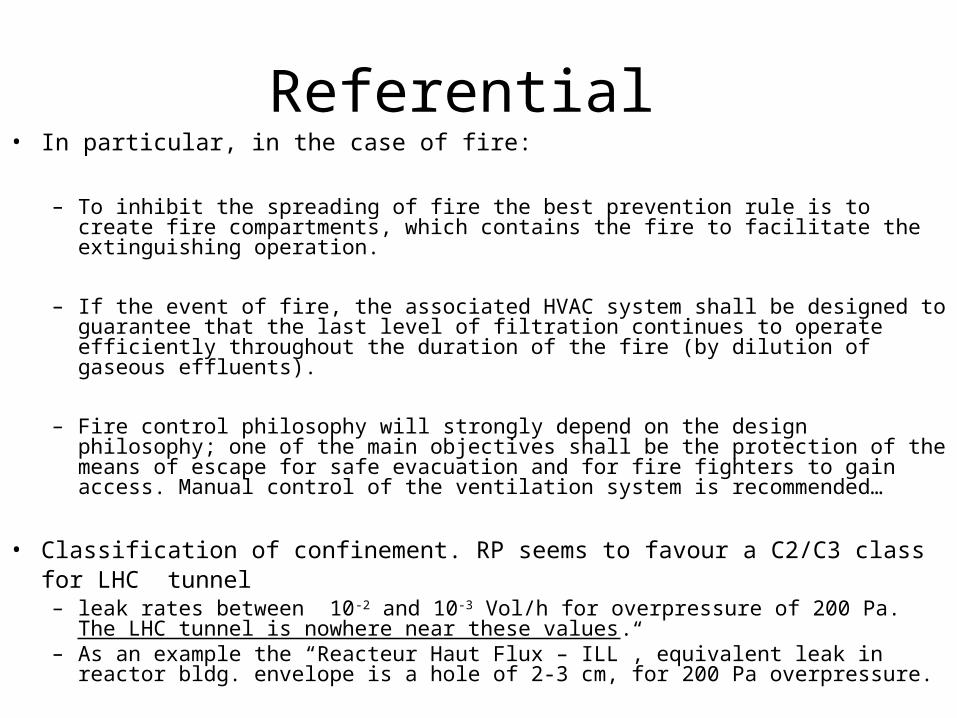
Referential • In particular, in the case of fire:
– To inhibit the spreading of fire the best prevention rule is to create fire compartments, which contains the fire to facilitate the extinguishing operation.
– If the event of fire, the associated HVAC system shall be designed to guarantee that the last level of filtration continues to operate efficiently throughout the duration of the fire (by dilution of gaseous effluents).
– Fire control philosophy will strongly depend on the design philosophy; one of the main objectives shall be the protection of the means of escape for safe evacuation and for fire fighters to gain access. Manual control of the ventilation system is recommended…
• Classification of confinement. RP seems to favour a C2/C3 class for LHC tunnel – leak rates between 10-2 and 10-3 Vol/h for overpressure of 200 Pa. The LHC
tunnel is nowhere near these values. – As an example the “Reacteur Haut Flux – ILL”, equivalent leak in reactor bldg.
envelope is a hole of 2-3 cm, for 200 Pa overpressure.

How to move closer to the present referential?
In view of the functions related to safety in ISO 17873, the main axes to develop should be:
• Confinement
• Availability/Reliability
• Filtration
• Monitoring
• Smoke extraction procedures

ConfinementThe confinement between adjacent underground areas depends largely on “architectural items” outside the HVAC system.
• No confinement between the UAs-RAs (openings for services). The UA is part of the LHC tunnel. Confinement of the LHC tunnel achieved by ventilation doors in the ULs.
• Confinement along the LHC tunnel arcs not possible with present HVAC layout. The use of booster fans as part of the design is strongly discouraged by the standards.
• Pressurised access modules have acceptable confinement. Door contacts should be installed and door closers regularly inspected and maintained. This item of major importance during shutdown periods.
• Experimental caverns and their underground accessible areas need further improvements in static confinement. CMS experience very positive.

Availability/Reliability
1. All underground ventilation systems feature redundancy of mechanical elements.
2. No back-up power supply.
All HVAC cut by emergency stop except shaft pressurisations and roof extraction fans SDs, SDXs, SMI. Major modifications necessary to provide the necessary power for tunnel HVAC supply and extraction, cold smoke extraction, etc.
3. Control system/power supply cubicles single point of failure.
“Retour d’experience”: Very few problems in the past.
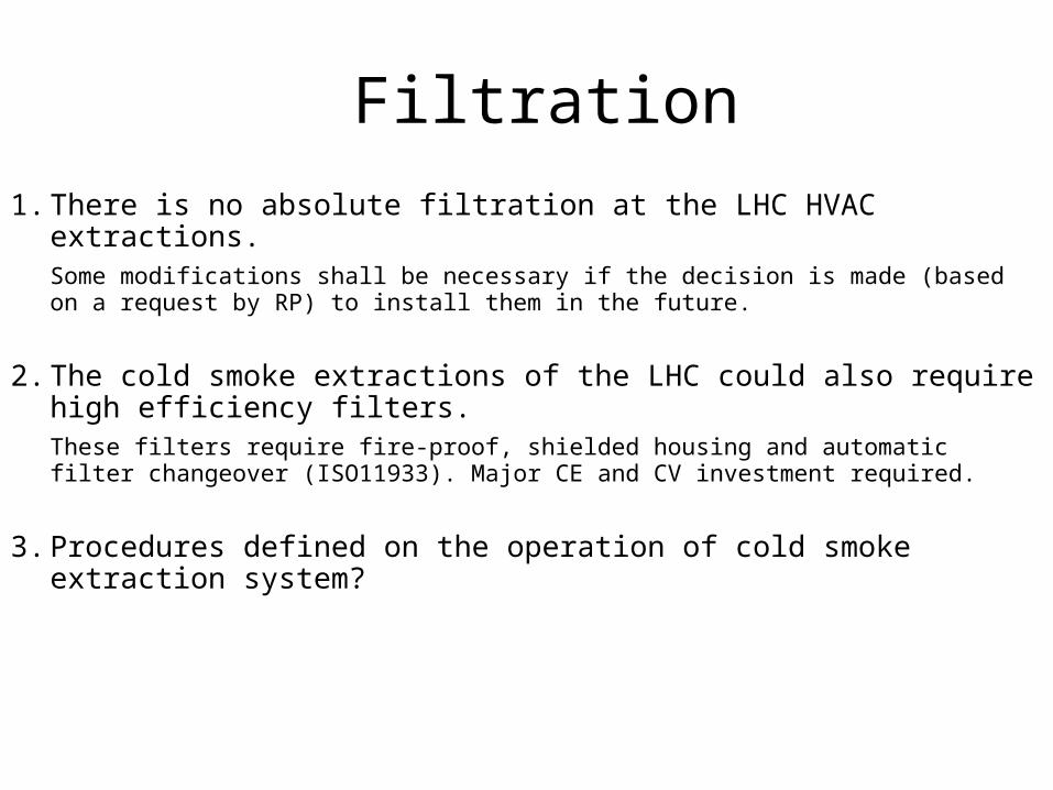
Filtration
1. There is no absolute filtration at the LHC HVAC extractions. Some modifications shall be necessary if the decision is made (based on a request by RP) to install them in the future.
2. The cold smoke extractions of the LHC could also require high efficiency filters. These filters require fire-proof, shielded housing and automatic filter changeover (ISO11933). Major CE and CV investment required.
3. Procedures defined on the operation of cold smoke extraction system?

Monitoring
1. Monitoring system for the HVAC parameters being completed. Operational parameters broadcast via DIP (Data Interchange Protocol).
2. The LHC HVAC system does not monitor the presence of flow in the arcs. A reliable solution not available but possibility to install independent functionality (L2) alarms for access shafts and accessible underground areas’ pressurisation wired to the MMD/DSS for increased safety.
For experiments the X control rooms can determine procedures based on this information.
For LHC tunnel the functionality alarms from the HVAC together with door contacts can be used as indirect means to determine if arc ventilated during shutdown periods.
3. HVAC monitoring independent of RAMSES measurements.
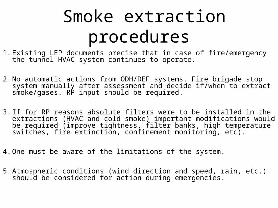
Smoke extraction procedures1. Existing LEP documents precise that in case of fire/emergency the tunnel
HVAC system continues to operate.
2. No automatic actions from ODH/DEF systems. Fire brigade stop system manually after assessment and decide if/when to extract smoke/gases. RP input should be required.
3. If for RP reasons absolute filters were to be installed in the extractions (HVAC and cold smoke) important modifications would be required (improve tightness, filter banks, high temperature switches, fire extinction, confinement monitoring, etc).
4. One must be aware of the limitations of the system.
5. Atmospheric conditions (wind direction and speed, rain, etc.) should be considered for action during emergencies.

Conclusions1. The existing LHC HVAC system is inherited from LEP. It has undergone
no upgrade to conform to new regulations.
2. Recent ISO standards provide a relevant referential for possible improvements. The major improvement axes would be:
– Confinement and filtration,– Availability and reliability,– Monitoring,– Procedures,
3. However full adherence to the ISO impractical and costly for the LHC.
4. Improvement of some aspects very affordable (door contacts, independent alarms).
5. Some modifications (filtration of smoke, back-up electrical supply) very costly and require careful consideration.


