EUROPEAN ORGANIZATION FOR NUCLEAR RESEARCH CERN ⎯ A&B DEPARTMENT Geneva, Switzerland November, 2006 AB-Note-2006-046 (CO) The LHC Logging Service Capturing, storing and using time-series data for the world's largest scientific instrument R. Billen, C. Roderick Abstract CERN, the European Laboratory for Particle Physics, is well underway in building the most powerful particle accelerator called LHC (Large Hadron Collider), which will probe deeper into matter than ever before. This circular 27-km long superconducting installation is extremely complex, and its functioning has to be closely monitored. The LHC Logging service is aimed to satisfy the requirement of capturing and storing of any relevant piece of information to track its variation over time. Web-deployed tools have been developed to visualize, correlate and export the data into dedicated off-line analysis tools. The quality of the data, the manageability of the service and the overall system performance are key factors for the service. Oracle technology has been used extensively to support this mission-critical service, which has proven already to be useful during the commissioning phase of individual subsystems of the LHC. The architecture, design and implementation of the LHC Logging service, based on Oracle Database, Application Servers and the Enterprise Manager, are described in this paper. Paper presented at the UKOUG Conference 2006 14-17 November 2006, Birmingham, UK brought to you by CORE View metadata, citation and similar papers at core.ac.uk provided by CERN Document Server
Transcript
EUROPEAN ORGANIZATION FOR NUCLEAR RESEARCH CERN ⎯ A&B DEPARTMENT
Geneva, Switzerland November, 2006
AB-Note-2006-046 (CO)
The LHC Logging Service
Capturing, storing and using time-series data for the world's largest scientific instrument
R. Billen, C. Roderick
Abstract CERN, the European Laboratory for Particle Physics, is well underway in building the
most powerful particle accelerator called LHC (Large Hadron Collider), which will probe deeper into matter than ever before. This circular 27-km long superconducting installation is extremely complex, and its functioning has to be closely monitored. The LHC Logging service is aimed to satisfy the requirement of capturing and storing of any relevant piece of information to track its variation over time. Web-deployed tools have been developed to visualize, correlate and export the data into dedicated off-line analysis tools. The quality of the data, the manageability of the service and the overall system performance are key factors for the service. Oracle technology has been used extensively to support this mission-critical service, which has proven already to be useful during the commissioning phase of individual subsystems of the LHC. The architecture, design and implementation of the LHC Logging service, based on Oracle Database, Application Servers and the Enterprise Manager, are described in this paper.
Paper presented at the UKOUG Conference 2006 14-17 November 2006, Birmingham, UK
brought to you by COREView metadata, citation and similar papers at core.ac.uk
1. Introduction............................................................................................................................................... 3 1.1. CERN............................................................................................................................................... 3 1.2. Accelerators and experiments .......................................................................................................... 3 1.3. The LHC Project .............................................................................................................................. 3
2. The LHC Logging Project ........................................................................................................................ 4 2.1. The need for time-series data logging .............................................................................................. 4 2.2. Initial system requirements .............................................................................................................. 4 2.3. Overall software environment.......................................................................................................... 4 2.4. Data sources ..................................................................................................................................... 4 2.5. Integration with other projects ......................................................................................................... 5
3. Oracle environment................................................................................................................................... 6 3.1. In-house usage and expertise of Oracle technology......................................................................... 6 3.2. Current boundary conditions............................................................................................................ 6 3.3. Anticipating technology evolution................................................................................................... 6
4. Architecture .............................................................................................................................................. 7 4.1. High-Level Software Architecture ................................................................................................... 7 4.2. Hardware and System Software ....................................................................................................... 8
5. Service Design & Implementation............................................................................................................ 9 5.1. Database Schema Design ................................................................................................................. 9 5.2. Database Schema Implementation ................................................................................................. 10 5.3. Data Loading API’s ....................................................................................................................... 10 5.4. Data Correlation and Extraction..................................................................................................... 11 5.5. Database Techniques Used ............................................................................................................ 12 5.6. Development Tools ........................................................................................................................ 13 5.7. Runtime environments ................................................................................................................... 13 5.8. Diagnostics & Error Handling ....................................................................................................... 13
6. Lessons learned: the good and the bad news .......................................................................................... 15 6.1. Handling huge data volumes.......................................................................................................... 15 6.2. Getting the data access right .......................................................................................................... 15 6.3. Knowing what’s going on .............................................................................................................. 15
7. Evolution and future direction ................................................................................................................ 16 7.1. Scalability....................................................................................................................................... 16 7.2. Planned upgrades ........................................................................................................................... 16 7.3. Unexplored possibilities................................................................................................................. 16
A. Terms ...................................................................................................................................................... 18 B. Abbreviations.......................................................................................................................................... 18
The LHC Logging Service
3
1. Introduction
1.1. CERN
CERN is the European Organization for Nuclear Research, the world's largest particle physics centre, located on both sides of the Franco-Swiss border near Geneva.
CERN is a laboratory where scientists unite to study the building blocks of matter and the forces that hold them together. CERN exists primarily to provide them with the necessary tools. These tools are accelerators, which accelerate particles to almost the speed of light
and detectors to make the particles visible.
Founded in 1954, the laboratory was one of Europe's first joint ventures and includes now 20 Member States.
Very soon, the work at the laboratory went beyond the study of the atomic nucleus, on into higher and higher energy densities. Therefore, from early on, we have been a high-energy physics institute. Because this activity is mainly concerned with the study of interactions between particles, the laboratory operated by CERN is commonly referred to as the "European laboratory for particle physics" and it is this latter title that really describes the current work of the Organization.
CERN does pure scientific research into the laws of nature. Since its creation, CERN has made many important discoveries for which CERN scientists have received prestigious awards, including Nobel prizes. CERN is also the birthplace of the World Wide Web.
1.2. Accelerators and experiments
Particles are extremely tiny, and to be able to see and study them, scientists need very special tools. They need accelerators – huge machines able to speed up particles to very high energies before smashing them into other particles.
Around the points where the "smashing" occurs, scientists build experiments which allow them to observe and study the collisions. These are instruments, sometimes huge, made of several kinds of particle detectors.
By accelerating and smashing particles, physicists can identify their components or create new particles, revealing the nature of the interactions between them.
The accelerator complex at CERN is a succession of machines with increasingly higher energies, injecting the particle beam each time into the next one, which takes over to bring the beam to an even higher energy, and so on. The flagship of the complex will be the Large Hadron Collider.
1.3. The LHC Project
The Large Hadron Collider (LHC) is a particle accelerator which will probe deeper into matter than ever before. The LHC is being built in a circular tunnel 27 km in circumference, 50 to 175 m underground, and is due to switch on in 2007.
The LHC will be one of the most complex installations ever built in a wide range of technologies such as civil engineering, ultra-high vacuum, magnets, electronics, and especially superconductivity. To keep the particles on track in the LHC, extremely strong magnetic fields need to be produced.
Superconductivity makes such fields possible, but a superconducting installation as large as the LHC will be a world première. The LHC will operate at about 290 degrees below room temperature, a few degrees above the absolute zero. With its 27 km circumference, the accelerator will be the largest superconducting installation in the world.
The LHC Logging Service
4
2. The LHC Logging Project
2.1. The need for time-series data logging
The LHC will be an installation of unprecedented complexity, with dense high-energy particle beams that can potentially damage the equipment of the machine itself. Hundred-thousands of signals coming from equipment surveillance and beam observation will be monitored to carefully examine the behaviour of this machine. Cryogenics temperatures, magnetic field strengths, power dissipation, vacuum pressures, beam intensities and positions are all parameters that will influence the correct functioning and performance of the installation as a whole. Each of the subsystems has its own data acquisition system to track parameter values over time. In order to be able to correlate this heterogeneous information, the data is “logged” in a central database. This allows end-users to visualize and extract any data, compare over time, examine trends, find patterns and discover relationships between apparently unlinked parameters.
The need and value for such centralized logging was already demonstrated on previous occasions: • LEP Logging: data logging for CERN’s previous flagship accelerator, the Large Electron-Positron
collider (LEP), operated from 1989 till 2000. • LHC-string Logging: data logging from the prototype LHC magnet test stand, operated from 2001
till 2003. Based on these experiences, the LHC Logging project was launched in October 2001. The first operational implementation was used in autumn 2003. Since then, the service has been evolving continuously to the current situation as described in this paper.
2.2. Initial system requirements
Typically there are two types of clients acting as data providers: equipment hardware related and particle beam related. The equipment data is progressively and increasingly available before the LHC start-up, as the individual subsystems go through their hardware commissioning. Beam data will only become available when the LHC will be fully commissioned with the green light to receive the first particles from the injecting accelerator chain.
The first interviews with the potential data providers resulted in some rough figures on data volumes. The exponential increase is foreseen to stabilise after the first year of beam operation around the level of 5 terabyte per year. The historic data of previous years would be kept on-line in the same data store, in order to facilitate data comparison over the lifetime of the LHC. Performance requirements on throughput and latency could not be quantified at the start of the project. Consequently, the design had to be correct, with scalability anticipated.
2.3. Overall software environment
During the 80’s and 90’s, the accelerator controls software environment was purely procedural, mainly with business logic implemented in the C programming language. A new strategic direction was chosen just before the millennium change, opting for Java object-oriented software for all custom application development. In addition, industrial solutions were introduced with supervisory control and data acquisition (SCADA) systems on top of programmable logic controllers (PLC).
Another paradigm shift concerns the deployment of the client applications, traditionally deployed and running on the client platform. Today, most applications run in a 3-tier architecture, many of which are Web-enabled with just the browser running on the end-user platform. The latter is the case for the graphical user interfaces (GUI) of the logging service.
2.4. Data sources
The data sources are very heterogeneous due to the specificities of the individual data acquisition systems. In order to have some standardization in the data capture process, a limited number of application programming interfaces (API) were developed and made available to the data providers. The APIs differ with respect to their data transfer mechanisms on which they are based:
The LHC Logging Service
5
• XML file based: to optimize bulk data loading from industrial systems, enforce parsing and validity checks of the submitted data.
• JDBC based: to serve Java clients and optimize frequent data input. • PL/SQL based: for transferring data already stored in an Oracle database.
These published APIs have to be rigorously used by the data providers, no other means for writing in the database is allowed.
2.5. Integration with other projects
The logging service is not an isolated tool to monitor the performance of the LHC and its subsystems. Its functionality needs to be combined with other services to get a more complete picture of the machine behaviour, especially when things go wrong. The Logging service is designed to be a steady, continuous, long-term data capturing tool, for a wide range of clients. On the other hand, it has to be considered as relatively slow. The most rapid entry point – the Measurement Service – deals with data input rates up to a few hertz. The following services have complimentary functionality:
• Post-Mortem service: collects and analyzes transient recordings, i.e. buffers of rapid data points (kilohertz range) from a set of crucial LHC subsystems, triggered by special events.
• Alarm service: centralizes notifications that indicate malfunctioning of any component to inform control room operators, and incite them for immediate action.
Two prerequisites to allow a smooth integration of the services have been enforced: coherent time-stamping and consistent identification of the data.
The LHC Logging Service
6
3. Oracle environment
3.1. In-house usage and expertise of Oracle technology
CERN was one of the first European companies to have purchased Oracle as data management systems in 1983 (version 2.3). Since then, many operational systems have been developed with the Oracle database as foundation, both in CERN’s administrative services and the domain of accelerator technology and controls. Given the accumulated investment and experience gained over two decades, the choice for Oracle as resource tier is a no-brainer.
3.2. Current boundary conditions
Oracle Server technology is the standard relational data management system (RDBMS) at CERN. Database administration (DBA) is taken care of by CERN’s information technology (IT) department, while database and software design is in the hands of decentralized software development teams. Depending on the requirements for each specific database service, the necessary hardware and system software infrastructure is established by IT. In general, only the terminal release of an Oracle version is deployed as operational production platform. From the original prototype development up to the current production environment, the logging service has been powered by Oracle9i.
3.3. Anticipating technology evolution
Starting relatively early with the project, some five years before the full blown operational use of the service, the evolution of the technology needed to be taken into account. In this context, a number of strategic decisions have been made right from the start. Basically, it boils down to going for the latest technology, as soon as possible:
• Database technology: the design and implementation details were made, based on the technology of Oracle9i, despite the fact that this version was not at our disposal at the project start. We have pushed the DBAs in the IT department to keep closer in step with the latest Oracle RDBMS release. Early 2007, it is anticipated to migrate to Oracle Database 10g Release 2, Enterprise Edition.
• Application Servers: with Java as the application platform for all new projects, an in-depth evaluation was made in 2003-2004 to compare J2EE deployment solutions. The final choice ended up between the standalone Oracle container for Java (OC4J) and the complete Oracle Application Server (OAS). Right from the start, the Logging project opted for the OAS, in order to benefit from the extended possibilities, ease of installation and maintenance and surely a better support.
• Enterprise Manager: Oracle’s Enterprise Manager allows simple monitoring, diagnostics and repair of the deployed service. Anticipating that these actions will be partially performed by control room operators in the future, this approach was immediately pursued. Only the application servers are currently monitored, while potentially the complete service, including the database, could be managed.
The LHC Logging Service
7
4. Architecture
4.1. High-Level Software Architecture
Figure 4.1 shows the software architecture of the Logging Service. Central to the service is the LHC Logging Database (LDB) where logged time series data will be stored beyond the lifetime of the LHC machine.
Figure 4.1 LHC Logging Service – Software Architecture
Time series data is sent to the LDB via one of three methods: • The first method is via dedicated Oracle application servers. This method involves sending data in
XML files over HTTP to a Java Servlet running on the application server. Users are authenticated and authorized; the XML data is parsed and then sent to the LDB using JDBC. This method is currently used by all data logging based on the PVSS industrial SCADA systems.
• The second method is via the dedicated Measurement Database (MDB), where time series data are logged at up to a 2Hz rate. Data is entered into the MDB by Java clients using a dedicated Java client API based on JDBC. This raw, unfiltered data is kept for 7 days. However, every 15 minutes a database process checks the data, and according to some criteria: derives aggregate values, determines data of interest, and transfers the resulting data set to the LDB using PL/SQL.
• The third method of data logging is directly via the PL/SQL API as used by the Measurement database. This method is used by the Technical Services department who have a dedicated Oracle database (similar to the MDB) used for capturing and short term storage of 14 days. Once per hour they transfer data of interest to the LDB.
The LHC Logging Service
8
One of the goals of the Logging Service is the ability to correlate data coming from different systems. As per data input, there are three methods of data extraction available:
• The main method for data extraction is via a Java Web application based on Struts, running on the Oracle application servers. This allows the extraction and correlation of data stored in either the LDB, or the MDB.
• In some cases there is a need to include logged data in application programs. Since these programs tend to be written in Java there is a Java API which is built around Java database connectivity (JDBC), and enables the extraction of data as Java objects.
• The third means of data extraction is via a read-only database account. This option is discouraged since it presents the dangerous possibility that end-users will write some inefficient SQL having a negative effect on the entire service.
4.2. Hardware and System Software
The following components make up the hardware core of the service, namely the database server and the applications servers.
The real application cluster (RAC) is composed of two SUN servers, sharing the disks that add up to 1.7 TB of raw storage capacity. Mainly due to the mirroring, the usable storage for data is however less than half. The system will be expanded in the future at the end of this year, to significantly increase the storage capacity.
The purpose of the RAC is to offer 365 x 24 to the database, and with dual ‘everything’ to avoid any single point of failure. Currently the MDB and LDB are instances running on the same Oracle RAC database.
The host computers for the application servers, used for data loading and extraction, are HP Proliant machines. As they are not clustered yet, the failover and load balancing is done manually. The initial memory size of 1 GB was increased to cater for the memory hungry Java processes.
In order to have an Oracle certified configuration, the native RedHat Linux operating system is installed on these hosts. This is exceptional with respect to the majority of the accelerator backend or front-end servers, where an adapted version of the operation system is installed with a set of additional facilities.
The gigabit Ethernet networks on which these hosts are hooked up is also ensured by the IT department.
Application Server hosts technical details Two HP Proliant DL380
Dual 2.8 GHz CPU 2.5 GB RAM Dual power supply
RedHat Linux ES release 3 Oracle Application Server 10g (9.0.4.2.0)
Database host technical details Two SUN Fire V240
Dual 1 GHz CPU 4 GB RAM Dual internal disks Dual power supply
SUN StorEdge 3510FC disk array 2-Gb fiber channel bus Dual RAID controller 1 GB cache 12 x 146 GB 10k rpm FC disks 24 x 300 GB 10k rpm FC disks (2007)
SUN Solaris 9 Veritas Volume Manager 3.5 Oracle9i Enterprise Edition Release 9.2.0.7.0
The LHC Logging Service
9
5. Service Design & Implementation
5.1. Database Schema Design
The main objective of the databases within the LS is to store time series data. Time series data is comprised of 3 essential pieces of information:
• An identifier: specifying what the data belongs to. • A timestamp: specifying the moment in time that the data corresponds to. • A value: specifying the measured value(s) at the given time.
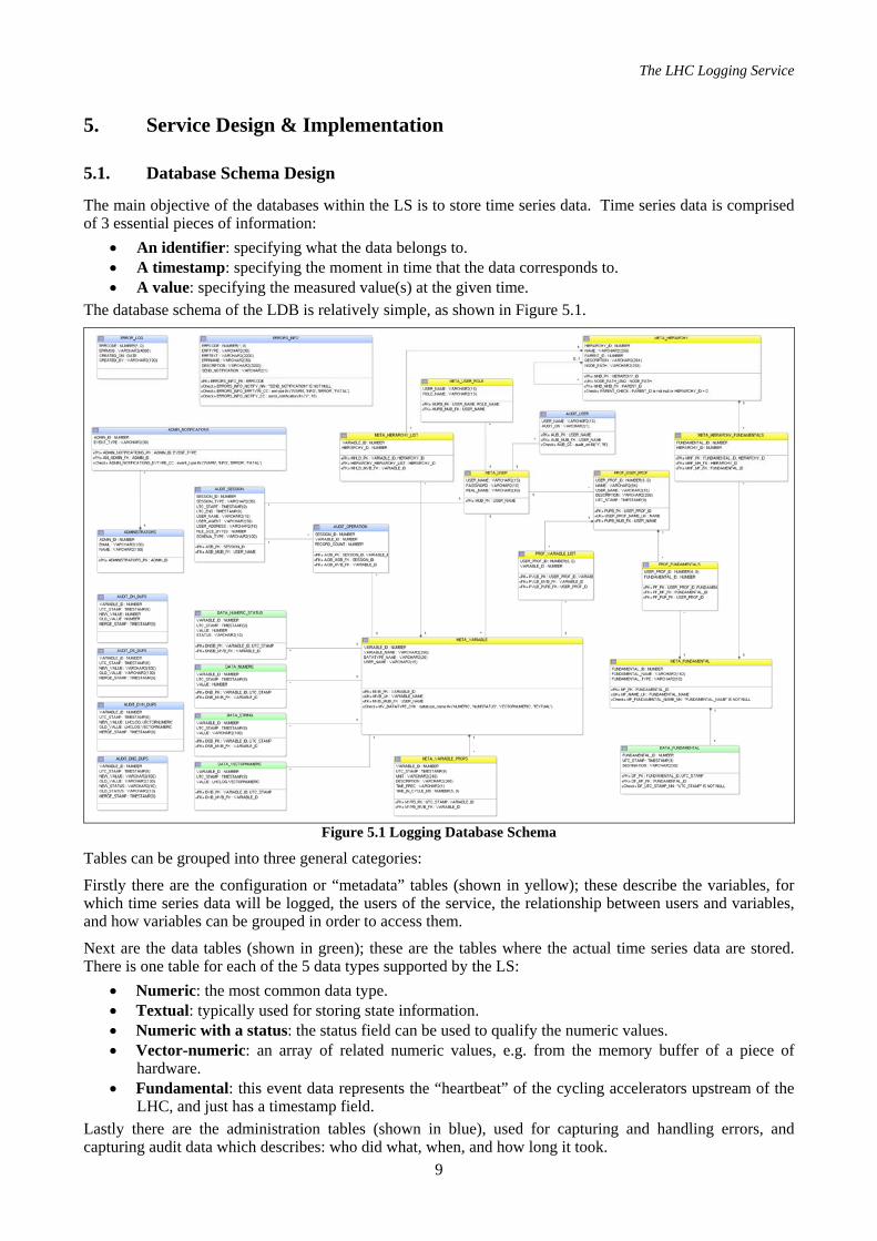
The database schema of the LDB is relatively simple, as shown in Figure 5.1.
Figure 5.1 Logging Database Schema
Tables can be grouped into three general categories:
Firstly there are the configuration or “metadata” tables (shown in yellow); these describe the variables, for which time series data will be logged, the users of the service, the relationship between users and variables, and how variables can be grouped in order to access them.
Next are the data tables (shown in green); these are the tables where the actual time series data are stored. There is one table for each of the 5 data types supported by the LS:
• Numeric: the most common data type. • Textual: typically used for storing state information. • Numeric with a status: the status field can be used to qualify the numeric values. • Vector-numeric: an array of related numeric values, e.g. from the memory buffer of a piece of
hardware. • Fundamental: this event data represents the “heartbeat” of the cycling accelerators upstream of the
LHC, and just has a timestamp field. Lastly there are the administration tables (shown in blue), used for capturing and handling errors, and capturing audit data which describes: who did what, when, and how long it took.
The LHC Logging Service
10
This simple schema design differs from logging system for the previous accelerator LEP, where dedicated tables for each type of entity producing time series data. The ‘data table per data type’ approach is supported by a recently introduced global naming scheme for all equipment, entities, signals, and parameters covering the whole CERN accelerator complex. The most obvious advantages of this approach are its scalability (there is no need to add more tables for new types of equipment), and the fact that the data are all stored together (which simplifies both data loading and extraction).
The MDB deals with the same type of data as the LDB, but it has some additional processing tasks concerning data derivation and data filtering prior to transfer to the LDB. Hence the MDB schema design includes all of the elements found in the LDB, plus some additional configuration tables to describe how time series data should be derived and filtered, and when it was last checked and logged.
5.2. Database Schema Implementation
To deal with the fact that vast amounts of data spanning more than 20 years will be stored in the LDB, range partitioning is employed for all tables which store time series data. Currently the partitions span month long periods. Having such partitions enables the Cost-Based Optimizer (CBO) to carry out partition elimination each time a user queries some time series data within a range that does not span all partitions.
Tablespaces for the time series data partitions are also mapped to one month periods. This allows the tablespaces for historic data to be flagged as read-only, which reduces the amount of time and resources required to backup the data.
The time series data tables are ‘skinny’ (3-4 columns), and because they will always be accessed by their primary keys (identifier and timestamp), and their data will not be updated – they are implemented as Index-Organized Tables (IOT). This reduces storage requirements and improves query performance compared to conventional heap tables, since there is no need to neither maintain nor query an additional index.
The time series data tables in the MDB are also implemented as range-partitioned Index-Organized Tables. However, in the MDB this approach is primarily for administration purposes. Since only 7-days of data are kept, the data is organized in daily range partitions, and a scheduled database process (DBMS_JOB) executes a procedure once per day – dropping the oldest partition, and adding a new partition. These partition maintenance operations use the UPDATE GLOBAL INDEXES clause (since 9i), avoiding the need to rebuild the global table index as a separate offline operation. It is worth noting that the table may contain several billion rows, depending on the actual operational scenario.
All time series data can be time stamped with up-to nanosecond precision, thanks to the use of the TIMESTAMP data type (since 9i). Most of the data has at least millisecond precision.
One of the time series data types supported by the LS is ‘Vectornumeric’ data. This is an array of numeric values, whose order must be preserved, and which will always be written and retrieved as an entire collection. For this reason it was decided that the Vectornumeric data would be stored in-line, as a VARRAY of NUMBER, next to its identifier and timestamp.
In addition to running a daily DBMS_JOB for partition maintenance, automated procedures are also executed on a regular basis to check the available storage, check for broken jobs, and to gather CBO statistics, and system usage statistics. The latter counts the number or records logged per user, per data type during the previous day. It also uses the analytic function LEAD to check changes to the logged values, and establish a count of the amount of repeating data (:NEW.logged_value = :OLD.logged_value).
5.3. Data Loading API’s
As seen in Figure 4.1, sending data to the LS involves passing via one of three categories of API: • XML: This is the original data loading API, and involves sending data conforming to one of three
XML schemas to a Java Servlet over HTTP. The Servlet uses a Java SAX XML parser, to extract the data as Java objects, and then the data is written to the database using the Oracle implementation of JDBC PreparedStatements with batch processing.
• Java: This API is intended for client–server data transfer, between Java clients and the MDB. The API forces clients to send data in batches (rather than row-by-row), and is again based on Oracle specific JDBC.
The LHC Logging Service
11
• PL/SQL: This API supports direct database to database transfer (e.g. MDB to LDB). Data is transferred as PL/SQL collections over a database link via an intermediate ‘data loading’ account. Data is inserted into the relevant data tables using PL/SQL bulk operations (BULK COLLECT and FOR ALL).
All API’s enforce user authentication and authorisation using database tables defining users, passwords, and roles. For the XML API running on the application server, the authentication and authorisation are implemented using the DataSourceUserManager class. The other APIs have custom implementations.
5.4. Data Correlation and Extraction
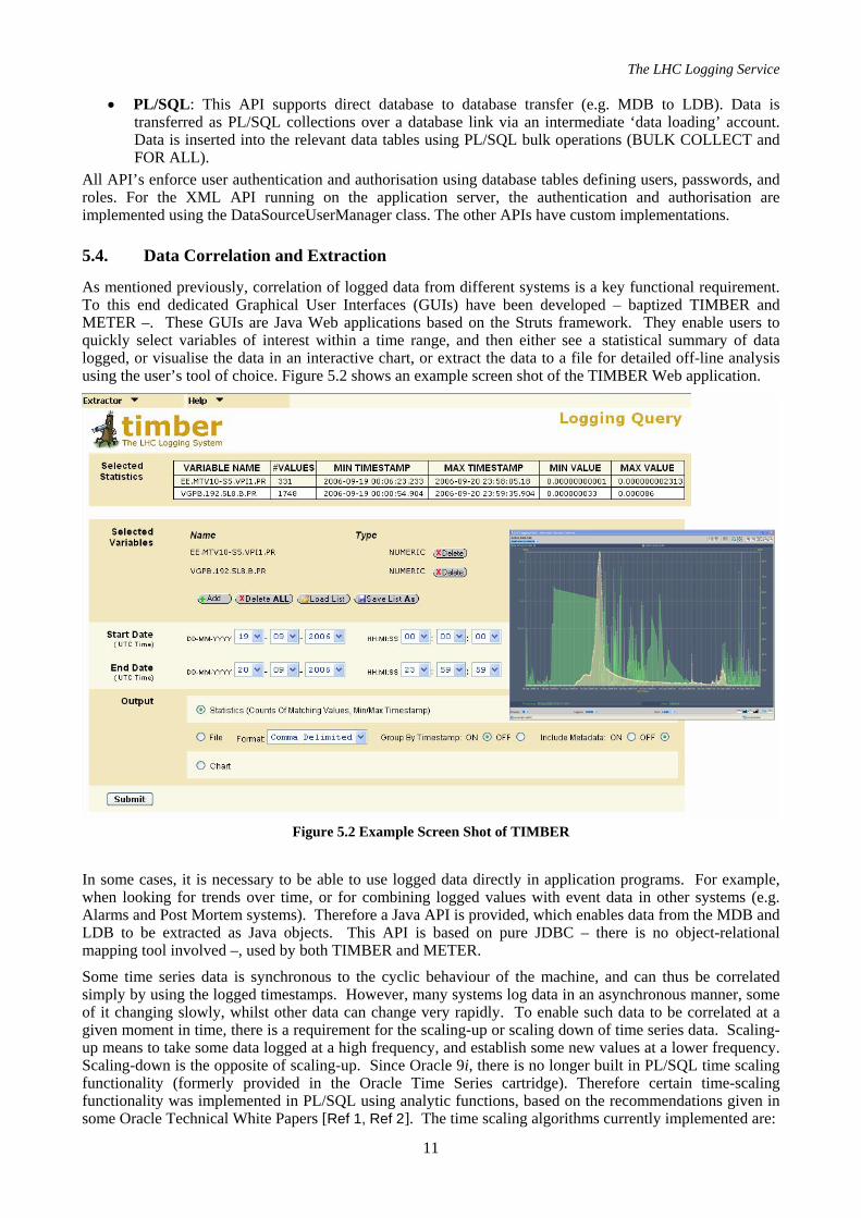
As mentioned previously, correlation of logged data from different systems is a key functional requirement. To this end dedicated Graphical User Interfaces (GUIs) have been developed – baptized TIMBER and METER –. These GUIs are Java Web applications based on the Struts framework. They enable users to quickly select variables of interest within a time range, and then either see a statistical summary of data logged, or visualise the data in an interactive chart, or extract the data to a file for detailed off-line analysis using the user’s tool of choice. Figure 5.2 shows an example screen shot of the TIMBER Web application.
Figure 5.2 Example Screen Shot of TIMBER
In some cases, it is necessary to be able to use logged data directly in application programs. For example, when looking for trends over time, or for combining logged values with event data in other systems (e.g. Alarms and Post Mortem systems). Therefore a Java API is provided, which enables data from the MDB and LDB to be extracted as Java objects. This API is based on pure JDBC – there is no object-relational mapping tool involved –, used by both TIMBER and METER.
Some time series data is synchronous to the cyclic behaviour of the machine, and can thus be correlated simply by using the logged timestamps. However, many systems log data in an asynchronous manner, some of it changing slowly, whilst other data can change very rapidly. To enable such data to be correlated at a given moment in time, there is a requirement for the scaling-up or scaling down of time series data. Scaling-up means to take some data logged at a high frequency, and establish some new values at a lower frequency. Scaling-down is the opposite of scaling-up. Since Oracle 9i, there is no longer built in PL/SQL time scaling functionality (formerly provided in the Oracle Time Series cartridge). Therefore certain time-scaling functionality was implemented in PL/SQL using analytic functions, based on the recommendations given in some Oracle Technical White Papers [Ref 1, Ref 2]. The time scaling algorithms currently implemented are:
The LHC Logging Service
12
• Scale-down repeat: This derives values at the chosen interval frequency, by repeating the last measured value just prior to each of the derived timestamp intervals. The measured values just before the derived timestamp intervals are established using the analytic function LAG.
• Scale-down interpolate: This derives values at the chosen interval frequency, by applying linear interpolation to the measured values just before and just after each of the derived timestamp intervals. The measured values just before and after the derived timestamp intervals are established using the analytic functions LAG and LEAD respectively.
• Scale-up MIN/MAX/AVG: This derives values at the chosen interval frequency by truncating the timestamps of the measured time series data to the start times of the derived intervals, and then applying the aggregate functions MIN, MAX, and AVG to the measured values, using GROUP BY timestamp.
The above algorithms are accessible as PL/SQL functions, which return a table (user defined SQL Types) containing the time scaled data which can be included in a SELECT statement. The table data is returned using the PIPELINED clause (since 9i) which allows data to be returned row by row, without the need to first wait for the complete set of time scaled data to be derived. An example of the usage of one of the above functions is given below:
SELECT stamp, min_value, max_value, avg_value FROM TABLE( TIME_SCALE.SCALEUP( 'data_numeric', -- Name of table containing time series data 'variable_id', -- Name of column containing variable ID 24288, -- ID of variable for which data is to be scaled 1, -- No. of intervals between generated timestamps 'HOUR', -- Type of interval between generated timestamps '2006-08-22 00:00:00', -- Desired start time for generated data '2006-08-22 23:59:59', -- Desired end time for generated data 'utc_stamp', -- Name of column containing the raw timestamps 'value' -- Name of column containing the raw values ) ) ORDER BY stamp;
5.5. Database Techniques Used
Each release of Oracle brings new features and techniques which can be used to simplify existing implementations and/or improve performance. The logging service takes advantage of several Oracle features to obtain simple and efficient solutions:
• MERGE statement (since 9i): This statement is used in data loading APIs for insert and updates of metadata in single batches. Although time series data should not be update in theory, in practice due to equipment errors or client software configuration errors – data can occasionally be sent more than once. In these situations, the batch of data is merged (so that data loading clients do not stop with an exception); and the event is logged in a separate table via an update trigger on the time series data tables. It is then possible to identify which client to contact concerning the duplicate data, and provide them with the names of the offending equipment.
• SQL Types: Several SQL types are used as tools for loading and querying data. For example, the Time Scaling PL/SQL package (described in 5.4) uses SQL types to represent tables of time series data which can be used in SQL queries.
• BULK PL/SQL operations: The PL/SQL data loading API uses the BULK COLLECT and FORALL constructs to load data in batches rather than a traditional row-by-row approach. In fact all collections in PL/SQL are loaded using the BULK COLLECT clause. This simplifies the code, and improves performance.
• INTERVAL data types (since 9i): INTERVAL data types represent units of time, and are used extensively in PL/SQL, SQL queries, and DBMS_JOB scheduling. They add clarity to code thanks to their intuitive nature, and they allow arithmetic to be carried out upon them. This latter functionality is used when analysing the audit data collected for data loading operations – making it simple to establish the elapsed time between consecutive data loading sessions for each client.
• Multi-table inserts (since 9i): When inserting metadata, there is sometimes a need to insert into one table, or another depending on a given value. The multi-table insert statement is a CASE like insert statement which makes such an operation simple – removing the need for procedural logic in the relevant data loading API.
The LHC Logging Service
13
• Analytic functions: Particularly those analytic functions employing a time window clause have been used extensively. They bring a new power to SQL, allowing data to be queried, and checks to be made in a way that would before only have been possible by using procedural code. This gives better performance, and reduces development time. In addition to being used in the time scaling PL/SQL code, analytic functions are also used in the filtering of MDB data being transferred to the LDB, and in the analysis of audit data.
5.6. Development Tools
The development can be split into two domains: Java development and PL/SQL development. The Java development covers data loading and extraction APIs and the data visualization and extraction GUIs.
JDeveloper 10.1.3 is used for all Java development.
The PL/SQL development covers the PL/SQL data loading API, system administration, error handling, data filtering (from measurement database to logging database), time scaling, auditing, and data derivation. Since its release, Oracle SQLDeveloper has become the tool of choice for PL/SQL development.
The code base shared between JDeveloper and SQLDeveloper makes switching between the two environments very natural.
5.7. Runtime environments
We are using three runtime environments, each containing the complete setup of data loading APIs, the database, and the Application Server(s) running multiple OC4Js:
• Development: This is used for developing and testing features to satisfy new requirements; or upgrading existing implementations to use new techniques or technologies.
• Test: This environment is identical to the production environment in terms of hardware and software deployment. It is used by new clients of the logging service – allowing them to validate their software against our system. It is also the opportunity for the behaviour of new clients to be validated – ensuring that they conform to the requirements of the logging service – i.e. they send data in bulk, at appropriate frequencies, with filtering applied and numeric values rounded to necessary precisions. Data logged in this environment will either be deleted after an elapsed time, or transferred to the production environment – depending on client requirements.
• Production: This environment is for clients who have passed ‘validation’ in the test environment, and wish to continue logging data – to be stored beyond the lifetime of the LHC machine.
5.8. Diagnostics & Error Handling
Diagnostics can be split into two domains – system diagnostics, and system usage diagnostics:
System diagnostics are also split into two areas: • Database diagnostics: ViewDB is an in-house tool which enables developers and system
administrators alike, to get an overview of how a database is performing, and drill down into user sessions to see who is doing what, from where, and how.
• Application server diagnostics: Oracle Enterprise Manager Application Server Control is used to monitor application server usage and performance, and to access server and application log files. It is also used to restart application server components, to edit configuration files, and to modify runtime parameters of Web applications running in the various OC4J instances.
System usage diagnostics: are implemented based on audit tables which are populated by the various data loading APIs, database triggers, and automated procedures which analyse logged time series data. The data contained in these tables is extremely useful, as allows system administrators to monitor how the usage of the system evolves over time, and thus plan for new system resources in advance of when they are required. The data also serves to identify:
• Clients which violate the LS usage policy or encounter configuration or equipment problems. • To see how the system is performing. • To see the causes of bursts of activity (differentiating between new systems coming online, or
potential client configuration errors).
The LHC Logging Service
14
Exception handling in any system is of utmost importance since it deals with abnormal situations. As systems grow in scale, exception handling becomes even more important – allowing system administrators to be aware of problems in the shortest of delays; to see the conditions which caused a problem to occur; and to be aware client related problems before they are reported by users, which in turn can improve the service. Exception handling also allows APIs to behave in a predictable manner. The LDB and MDB both use an adaptation of the exception handling framework proposed by S. Feuerstein in Oracle Magazine [Ref 3]. The actual exception handling framework used, deals with the definition, capturing, treatment, and notification of exceptions. When an exception occurs, the system administrators will be informed (depending on the severity of the exception), and they will be able to establish what the exception was, who (if anybody) encountered the exception, and when it occurred.
The LHC Logging Service
15
6. Lessons learned: the good and the bad news
6.1. Handling huge data volumes
Dealing with billion-row tables and still experiencing good query performance is undoubtedly related to decisions taken at design time to store time series data as range partitioned, index-organized tables. The partitioning of time series data tables in the MDB are also of benefit for administrative purposes – dropping old partitions instead of deleting old data. However, with such an approach, care must be taken not to continuously invalidate objects required by end users, which depend on the underlying partitioned tables.
A design decision was for the Logging Service to support arrays of numeric data – storing them using a user defined VARRAY type called Vectornumeric. Although this has the advantage of storing the data in it’s original order, and in-line with its identifier and timestamp, it is not to say that it without problems. User defined types are not supported over database links, which means their data must first be converted to equivalent PL/SQL types and then back again in order to transfer data. They can also be problematic for bulk data processing operations, where the size of the VARRAY can vary greatly between one record and another. In the case when a VARRAY is very large, there can be memory issues, or a negative impact on performance when using FOR ALL clause to insert data with PL/SQL. The only solution would appear to be to use a very low LIMIT clause, but this negates the potential benefits of using the bulk operation in the first place. Finally, in order to compare the contents of VARRAYS (e.g. for filtering unchanged values) it is necessary to write a custom comparator.
6.2. Getting the data access right
The LS deals with a variety of data providers, each sending different volumes of data at varying rates. Getting representative CBO statistics for such a large set of heavily skewed data is proving to be an ongoing challenge. In some cases problems have been experienced due to a combination of skewed data and bind variable peeking. In such cases, it has proven necessary to force the use of certain execution paths in order to improve performance until further investigation leads to a more appropriate solution.
There is undoubtedly an impedance mismatch between application developers and database developers, therefore the provision of data reading and writing APIs is essential. Left to their own devices, application developers would surely bring the Logging Service to its knees.
The world is surely a better place since the introduction of analytic functions, which have proven to be extremely useful – simplifying development, and improving performance.
6.3. Knowing what’s going on
As mentioned previously, the Enterprise Manager Application Server Control is used for diagnostic and configuration purposes. It is an intuitive tool, has proved to be reliable and fulfilled the requirements of the LS for application server administration. However, it seems that its functionality has changed in the subsequent version. Some nice new features are provided, but some of the features which are currently used are no longer provided (e.g. changing application runtime parameters for user auditing). Hopefully this will be rectified in the future, but for the time being this blocks the upgrade of the application server version.
The auditing functionality available in the LS is invaluable, and the importance of the role it plays cannot be overemphasized. Without the captured audit data, the system would be effectively running ‘in the dark’ with system administrators blind to what was happening.
The LHC Logging Service
16
7. Evolution and future direction
7.1. Scalability
One of the main worries for the control system as a whole is the risk that the services do not scale. For that reason, a campaign of scalability tests is being organized for each of the individual subsystems. Undeniably, the logging service is far from its final load. On the other hand, it is very difficult to make correct estimations of the final load in terms of required throughput and volume rates, due to a number of reasons:
• Not all subsystems are currently available. • Fine details of data pushing capabilities of each subsystem are not known yet. • Rationalization of information (e.g. filtering, data reduction) if of low priority to the data providers. • Peak loads may occur unexpectedly from inexperienced clients.
The only reasonable approach we can take is to increase the resources of the service, i.e. • Number of application servers to handle the increasing number of balanced client processes. • Increase the number of nodes in the database RAC cluster to sustain the database activity. • Optimize disk controllers’ activity to make sure that an I/O bottleneck is avoided.
In principle, nothing will be fundamentally changed to the overall system design or the database design.
7.2. Planned upgrades
It is assumed that the growth of system requirements is sufficiently spread over time, so that the necessary upgrades and extensions can be planned and scheduled.
The lead time for installing a new host, the deployment of a new application server and the replication of the operational software is in the order of a week. In case of an emergency, this could be reduced to one or two days. A spare host can be easily found in the existing computing pool.
The extension of the database capacity, server or disks, is in the order of two months, as it requires authorized purchase, delivery and installation of the necessary hardware. For the year 2007, an extra raw disk capacity of 7.2 TB will be installed. The overall situation will be revised for the period beyond 2007.
7.3. Unexplored possibilities
In addition to the planned modifications to cater for adequate performance and scalability, there are a number of routes that have not been explored yet:
• Clustering of application server hosts at software or hardware level. • Automatic load balancing between the database servers. • Data replication on a redundant system to ensure 100% uptime. • Application notification of data modifications to avoid intense polling by external applications. • Bringing in an Oracle consultant for system tuning.
The LHC Logging Service
17
8. Conclusion The Logging Project resulted in an operational Logging Service that is used by an increasing number of clients. Victim of this success, it is vital to monitor the behaviour of the clients and the overall performance of the service. The design has been validated but the implementation has evolved continuously, making use of Oracle technology and advanced features as much as possible. Scalability has been intrinsically anticipated within the design, additional hardware needs to be foreseen and plugged in to meet to demands in due time.
Database tuning can still be improved, especially the database statistics gathering strategy is not perfectly defined, due to lack of experience. If there is one thing that we would do differently, it would be avoiding the use of object-oriented concepts inside the database.
We are convinced to have followed the right path and are looking forward to the full exploitation of the Oracle-powered logging service when CERN’s flagship LHC will produce its first scientific results.
References [Ref 1] Oracle Technical White Paper, “Migrating from Oracle Time Series to SQL Analytic Functions:
Scaleup and Scaledown Without Calendars”, November 1999.
[Ref 2] Oracle Technical White Paper, “Migrating from Oracle Time Series to SQL Analytic Functions: Time Series Functions”, November 1999.
[Ref 3] Managing Exceptional Behaviour, By Steven Feuerstein, Oracle Magazine Part 1, May/June 2003 http://www.Oracle.com/technology/oramag/Oracle/03-may/o33plsql.html Part 2, July/August 2003 http://www.Oracle.com/technology/oramag/Oracle/03-jul/o43plsql.html
The LHC Logging Service
18
Annex: Glossary
A. Terms Logging The practice of recording sequential data chronologically Logging Service Servicing infrastructure to capture, store and render time-series data for the LHC, based
on an Oracle database, data input APIs and data rendering GUIs Struts Open-source framework for developing Java web applications. It uses and extends the
Java Servlet API to encourage developers to adopt a Model-View-Controller architecture Timestamp Date/time tag that goes with each individual data event that is logged
B. Abbreviations API Application Programming Interface: is the interface to allow data to be exchanged between
software applications CBO Cost Based Optimizer: the Oracle engine compares different execution plans for a given SQL
statement and chooses the most cost-effective one, based on table statistics CERN The European Organization for Nuclear Research: the world's largest particle physics
laboratory, providing the infrastructure needed for high energy physics research DBA Database Administrator: person responsible for the environmental aspects of a database GUI Graphical User Interface: interface between the end-user and the computer system with
graphical images and text to represent the information and actions available to the user. HTTP Hypertext Transfer Protocol: a method used to transfer information on the World Wide Web IOT Index Organized Table: database object whereby the data itself is stored in the index structure JDBC Java Database Connectivity: an API for the Java programming language that defines how a
client may access a database J2EE Java Platform, Enterprise Edition: a programming platform for developing and running
distributed multi-tier architecture Java applications, based on modular software components running on an application server
LDB The Logging Database: the resource tier of the Logging Service LEP Large Electron Positron collider: particle accelerator and collider located at CERN, currently
dismantled, operated from 1989 until 2000 LHC Large Hadron Collider: particle accelerator and collider located at CERN, currently under
construction, scheduled to start operation in 2007 MDB The Measurement Database: short-term persistence for Java applications, one of the input
channels of the Logging Database; constituent of the Logging Service OAS Oracle Application Server: Oracle’s software platform including web server and J2EE
containers, used for deploying J2EE based applications OC4J Oracle Containers for J2EE: Oracle implementation of J2EE containers OEM Oracle Enterprise Manager: computer application grid solution to manage sets of databases
and application servers PLC Programmable Logic Controller: a computer system used for automation of industrial
procedural extension to the SQL database language PVSS Commercial SCADA system for object-oriented process visualization and control, by the
Austrian company ETM RAC Oracle’s Real Application Cluster: multiple computers run the Oracle RDBMS software
simultaneously while accessing a single database, i.e. a clustered database RDBMS Relational Database Management System: a database management system based on the
relational model SAX Simple API for XML: provides a mechanism for reading data from an XML document SCADA Supervisory Control and Data Acquisition: a distributed measurement and control system to
monitor or to control industrial processes SQL Structured Query Language: computer language used to create, modify, retrieve and
manipulate data from relational database management systems XML Extensible Markup Language: a way of describing data by means of a general-purpose