The LHCb Muon System Michela Lenzi / INFN of Florence On behalf of LHCb muon group: CAGLIARI, CBPF, CERN, LNF, FERRARA, FIRENZE, PNPI, POTENZA, ROMAI, ROMAII 9 th International Conference on Advanced Technology and Particle Physics Villa Olmo, Como 17-21 October 2005 Outline: • Overview of the LHCb Muon Detector • Detector requirements • Chamber design and specifications • Chamber construction and quality control • Conclusions
Transcript
The LHCb Muon System Michela Lenzi / INFN of Florence
On behalf of LHCb muon group:CAGLIARI, CBPF, CERN, LNF, FERRARA, FIRENZE, PNPI,
POTENZA, ROMAI, ROMAII
9th International Conference on Advanced Technology and Particle PhysicsVilla Olmo, Como 17-21 October 2005
Outline:• Overview of the LHCb Muon Detector• Detector requirements• Chamber design and specifications• Chamber construction and quality control• Conclusions
9th International Conference on Advanced Technology and Particle PhysicsMichela Lenzi October 17, 2005
Muon system overview
M1 M2 M3 M4 M5
5 Muon stations M1 in front and M2-M5 behind the calorimeters
Angular acceptances: 20 (16) – 306 (258) mrad in bending (non-bending) plane --> geometrical acceptance of ~ 20% for muons from b decays
435m2 of detector area with 1380 chambers
Purpose: muon triggering and offline muon identification
9th International Conference on Advanced Technology and Particle PhysicsMichela Lenzi October 17, 2005
Requirements
• Good time resolution => high efficiency (>99%) per station in a time window of 20ns (96% in M1)
• High rate capability => up to 0.5 MHz/cm2 for inner chambers at L = 5 x 1032 cm-1 s-1
• Good ageing resistance over 10 years• Good spatial resolution => pt resolution of triggering muons < 20%
Provide a fully efficient and robust level-0 high Pt muon trigger (through a 5-fold coincidence of hits in all stations) and bunch crossing identification:
9th International Conference on Advanced Technology and Particle PhysicsMichela Lenzi October 17, 2005
The Muon system
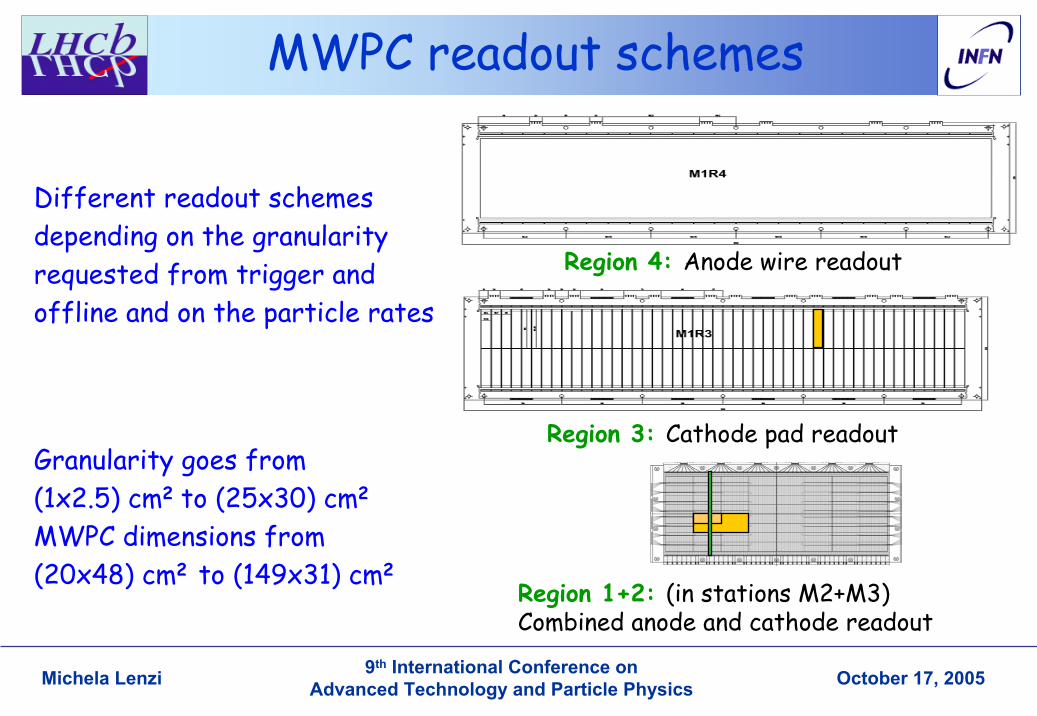
• 4 Regions/Station• Granularity shaped
according to particle density
• 20 different chamber dimensions for a total of 1380 chambers, mainly MWPC
• M1R1 triple-GEM – area = 1 m2 but
20% of triggering muons
– challenging for ageing, rate and time resolution
Region 4
Region 3
Region 2
4804
2002
1001
500
250
250
300 300 600 1200 2402
4003
Beam Pipe Sheilding
50mm x 250mm
25mm x�125mm
12.5mm x 63mm
6.3mm x�31mm
Logical channel
Logical channel
Logical pad
Reg 1
Chamber
9th International Conference on Advanced Technology and Particle PhysicsMichela Lenzi October 17, 2005
GEM detector: principle of operationThe GEM (Gas Electron Multiplier) is a thin (50 µm) metal coated kapton foil, perforated by a high density of holes (70 µm diameter, pitch of 140 µm)
By applying 400-500 V between the two copper sides, an electric field as high as ~100 kV/cm is produced into the holes which act as multiplication channels.
Gains up to 1000 can be easily reached with a single GEM foil. Higher gains are usually obtained by cascading two or three GEM foils.
Conversion &
A Triple-GEM detector is built by inserting three GEM foils between two planar electrodes, which act as the cathode and the anode.
But huge R&D on detector was needed!
9th International Conference on Advanced Technology and Particle PhysicsMichela Lenzi October 17, 2005
9th International Conference on Advanced Technology and Particle PhysicsMichela Lenzi October 17, 2005
Time resolution
• Optimum amplifier peaking time ~10ns• Intrinsic time resolution is less than 4ns
Time (ns) E
ntri
es
2.0mm pitch, wire readout
0
25
50
75
100
125
150
175
200
265 270 275 280 285 290 295 300 305 310 315
20ns
9th International Conference on Advanced Technology and Particle PhysicsMichela Lenzi October 17, 2005
Chamber Efficiency
HV (kV)
Eff
icie
ncy
(%)
2.0mm pitch, wire readout
25ns time window
20ns time window
15ns time window
70
75
80
85
90
95
100
2.3 2.4 2.5 2.6 2.7 2.8 2.9
WP
HV (kV)
Eff
icie
ncy
(%)
2.0mm pitch, cathode readout
25ns time window
20ns time window
15ns time window
70
75
80
85
90
95
100
2.3 2.4 2.5 2.6 2.7 2.8 2.9
WP
Cathode Efficiency: Anode Efficiency:
An efficiency perdouble gap > 95% is required. The logical OR of the two double gap ensures that ε > 99.8% per station will be reached.
9th International Conference on Advanced Technology and Particle PhysicsMichela Lenzi October 17, 2005
Status of construction• within 2 years ~ 1400 chambers have to be built in 6 production centers• ~ 45% of the chambers have been produced • Quality assurances (QA) is a key issue: test on 100% of production
9th International Conference on Advanced Technology and Particle PhysicsMichela Lenzi October 17, 2005
9th International Conference on Advanced Technology and Particle PhysicsMichela Lenzi October 17, 2005
Chamber specifications
Gas Gain variations:
Working point should not move out of the voltage plateau:from test-beams: plateau width ~ 150 V for 4-gap
lower limit ε>99% (2.55KV), upper limit: cluster size < 1.2 (2.7KV) Working point = 2620 V
Good bi-gap: maximum voltage change of ±50 V that corresponds to a gain change of a factor 1.4 double gap gain on 100% of area between [0.7G0, 1.4G0], where G0 is the 4-gap average
What chamber imperfections are allowed with this constraint?
9th International Conference on Advanced Technology and Particle PhysicsMichela Lenzi October 17, 2005
Quality controls
• Panel planarity: min 95 % of the surface within 50 min 95 % of the surface within 50 µµm, m, Max deviation < 100 Max deviation < 100 µmm
• Wire fixation bars thickness (half gap): min 95% within [2.45, 2.55] mm, min 95% within [2.45, 2.55] mm, all points within [2.42,2.58]all points within [2.42,2.58]
• Wire Pitch: min 95% within [1.95, 2.05] mm, all points within [1.90, 2.10]min 95% within [1.95, 2.05] mm, all points within [1.90, 2.10]• Wire Tension: all tension higher than 50 g, Max deviation < 0.1 Tall tension higher than 50 g, Max deviation < 0.1 T00
• Gas Leak Rate: leak rate < 2 mbar/hour (@5 mbar over pressure)leak rate < 2 mbar/hour (@5 mbar over pressure)• HV Conditioning and test: dark Current < 10 < 10 nAnA per gapper gap• Gas Gain Uniformity: double gap gain between [0.7G0, 1.4G0]• Cosmic rays test: detection efficiency > 95% in a 20 ns time window
Panel test:
Chamber test:
9th International Conference on Advanced Technology and Particle PhysicsMichela Lenzi October 17, 2005
Wire tension (1)
WTM hammer laser spot photodiode
WDM camera
The wire, mechanically excited by a mylar hammer, vibrates with its own fundamental frequency; the light of a laser beam is reflected on the wire and then detected by a photodiode whose signal is sent to a standard PC sound card and then analyzedT = 4µl2f0
2
Ferrara/Firenze
9th International Conference on Advanced Technology and Particle PhysicsMichela Lenzi October 17, 2005
Wire tension (1)
Time waveform Fast Fourier Transform
Wire number
Tens
ion
(g)
About 4 sec/wire with an accuracy of 0.2%
9th International Conference on Advanced Technology and Particle PhysicsMichela Lenzi October 17, 2005
Wire tension (2)
CERN, LNF, PN
PI
Example of wire mechanicalresonance peak:
The wire is forced to oscillate by a periodic HV applied to a sense wire place parallel and close to it.Maximum ∆C is automatically measured by a digital electronic circuit12 wires measured in parallel
1300 wires/hour
9th International Conference on Advanced Technology and Particle PhysicsMichela Lenzi October 17, 2005
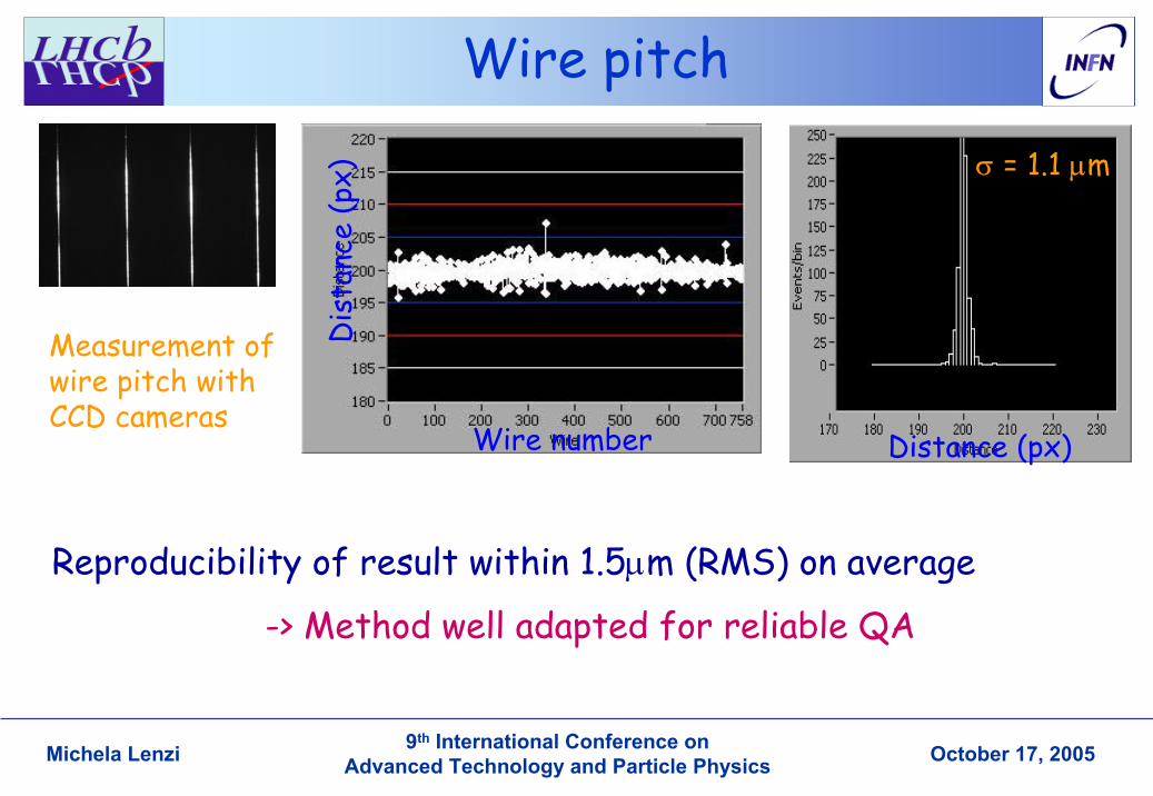
Wire pitch
Measurement of wire pitch with CCD cameras
Reproducibility of result within 1.5µm (RMS) on average
-> Method well adapted for reliable QA
Wire number
Dis
tanc
e (p
x) σ = 1.1 µm
Distance (px)
9th International Conference on Advanced Technology and Particle PhysicsMichela Lenzi October 17, 2005
Gap 1Gap 2Gap 3Gap 4
Gas gain uniformity
Corrections are applied for electron attenuation in different gaps and edge effects
Curr
ent
(nA
)
Pad number
Bi-gapAB
Bi-gapCD
Dou
ble
gap
gain
chamber number
9th International Conference on Advanced Technology and Particle PhysicsMichela Lenzi October 17, 2005
Cosmic ray test
95%
• 2 scintillator planes provide the triggers.• 4 chambers read out: 8 tracking layers.• 7 double-gaps are used to reconstruct the tracks and evaluate the efficiency of the 8th double-gap.
All tested double-gap arewell above the 95% threshold
chamber efficiency > 99% !!!
9th International Conference on Advanced Technology and Particle PhysicsMichela Lenzi October 17, 2005
Summary
• The LHCb Muon detector requirements are good time resolution, high efficiency, high rate capability, aging resistance• Extensive test have shown that our design of MWPC satisfies all the requirements• A trigger efficiency of 46% for b µX in the geometrical acceptance• All chambers are tested with automatic procedures• Construction is well advanced and the detector should be ready for the 1st LHC beams