The Linear Collider Alignment and Survey (LiCAS) Project Richard Bingham, Edward Botcherby, Paul Coe, John Green, Grzegorz Grzelak, Ankush Mitra , John Nixon, Armin Reichold University of Oxford Andreas Herty, Wolfgang Liebl, Johannes Prenting Applied Geodesy Group, DESY
Transcript
The Linear Collider Alignment and Survey (LiCAS) Project
Richard Bingham, Edward Botcherby, Paul Coe, John Green,Grzegorz Grzelak, Ankush Mitra, John Nixon, Armin Reichold
University of Oxford
Andreas Herty, Wolfgang Liebl, Johannes Prenting Applied Geodesy Group, DESY
7 March 2003
LiCAS Project: UCL Seminar 2
Contents
Introduction
Survey and Alignment of a Linear Collider
Survey Concept
LiCAS System Overview
Frequency Scanning Interferometry (FSI)
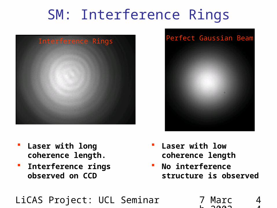
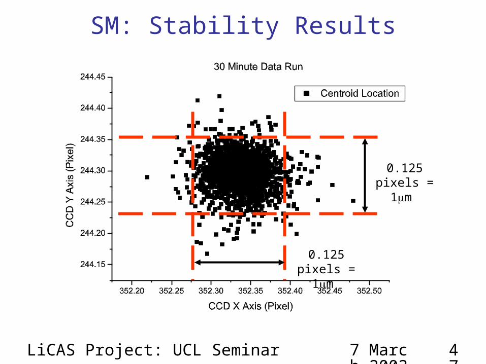
Straightness Monitors (SM)
Simulation of LiCAS performance
Summary
7 March 2003
LiCAS Project: UCL Seminar 3
Why do we need another collider ?
What’s wrong with the LHC ?• It’s a high energy, high luminosity hadron collider• Good as a discovery machine; eg: Higgs Hunting• But hadron colliders are messy
− Difficult to make precision measurements− Cannot determine quantum numbers of initial state
NEED A LEPTON COLLIDER
7 March 2003
LiCAS Project: UCL Seminar 4
Physics with a (Linear) Lepton Collider
LHC: Can see 120 GeV Higgs
LC: Can see 120 GeV Higgs more clearly
MH = 120 GeV, 3•104 pb-
1
S/B=3.6 (5.0 105 pb-1)
7 March 2003
LiCAS Project: UCL Seminar 5
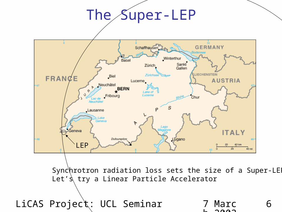
Why do we need a Linear Collider ?
Can’t we build a Super-LEP ?• Synchrotron Radiation
• For 1% Synchrotron radiation loss
4
/ RevE E
LEP II Super-LEP
Energy 180 GeV 500 GeV
E / Rev 1.5 GeV 5 GeV
Radius 4.3 km 255.8 km
Beam Energy
Bend Radius
7 March 2003
LiCAS Project: UCL Seminar 6
LEP
Synchrotron radiation loss sets the size of a Super-LEPLet’s try a Linear Particle Accelerator
The Super-LEP
7 March 2003
LiCAS Project: UCL Seminar 7
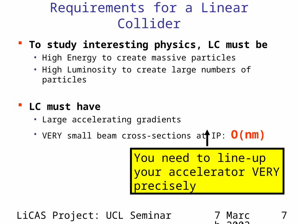
Requirements for a Linear Collider
To study interesting physics, LC must be• High Energy to create massive particles• High Luminosity to create large numbers of particles
LC must have• Large accelerating gradients
• VERY small beam cross-sections at IP: O(nm)
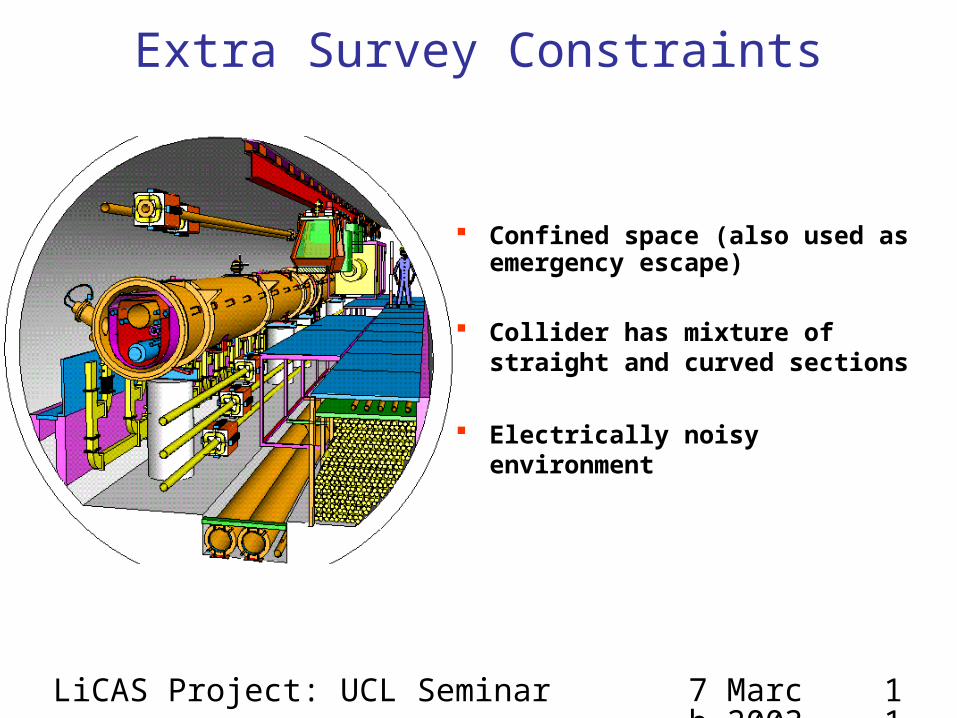
You need to line-up your accelerator VERY precisely
Accelerator Maintenance• If a component is replaced; the accelerator will be re-surveyed
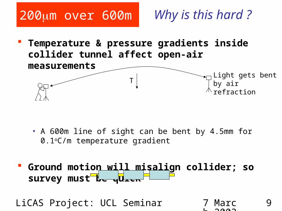
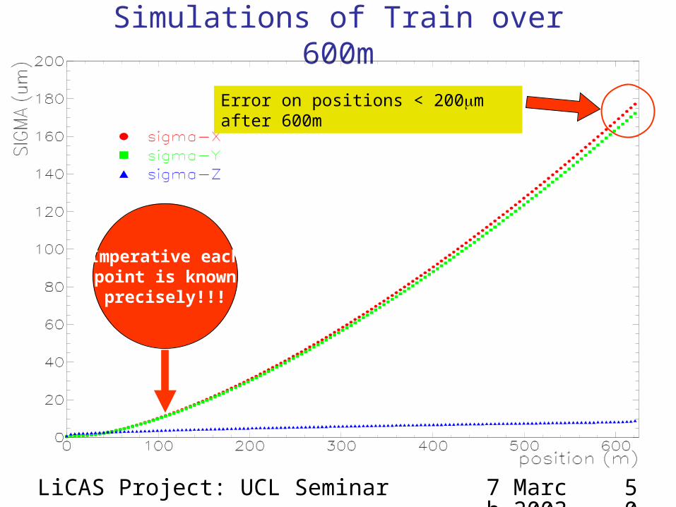
Each step has to achieve 200m over 600m precision
Accelerator Diagnostics• Check accelerator maintains alignment (& correct it)• Find out what went wrong
7 March 2003
LiCAS Project: UCL Seminar 13
Traditional Accelerator Surveys
A team of surveyors using theodolites, laser trackers, etc • Make precision measurements of accelerator site and
accelerator• A survey takes months to complete and requires a large team of
people.
But this approach is not suited to LC because:• Cannot achieve required accuracy • Slow• Manual• Large space required
7 March 2003
LiCAS Project: UCL Seminar 14
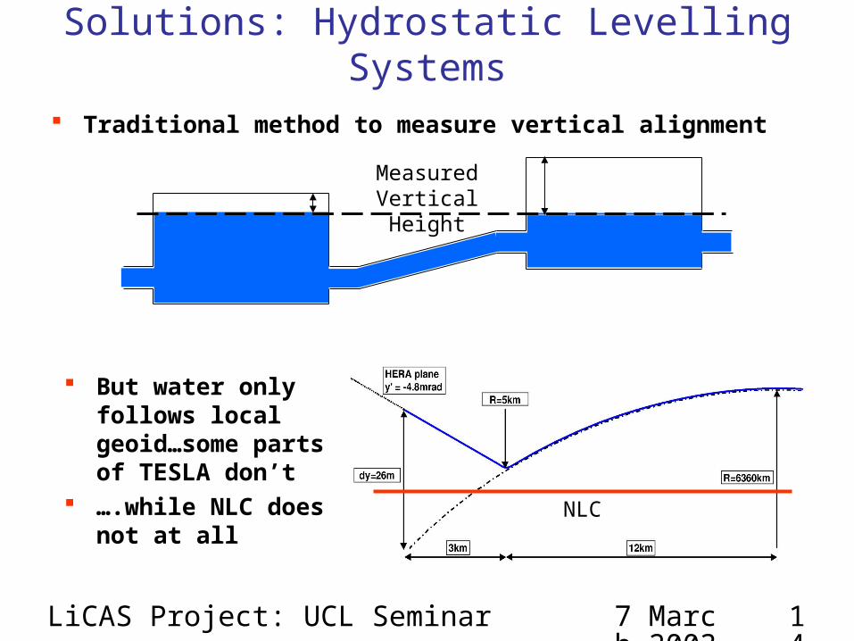
Solutions: Hydrostatic Levelling Systems
Traditional method to measure vertical alignment
But water only follows local geoid…some parts of TESLA don’t
….while NLC does not at all
Measured Vertical Height
NLC
7 March 2003
LiCAS Project: UCL Seminar 15
Other Solutions
Use a long stretched wire• The wire will sag under gravity: Only good for horizontal
alignment
Use a laser to align accelerator • In open-air, it will be refracted by temperature gradients• TESLA follows Earth’s geoid. So cannot be used for TESLA
7 March 2003
LiCAS Project: UCL Seminar 16
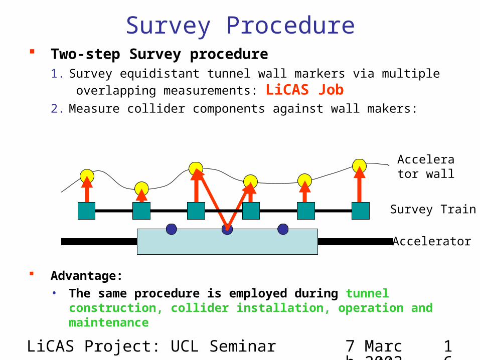
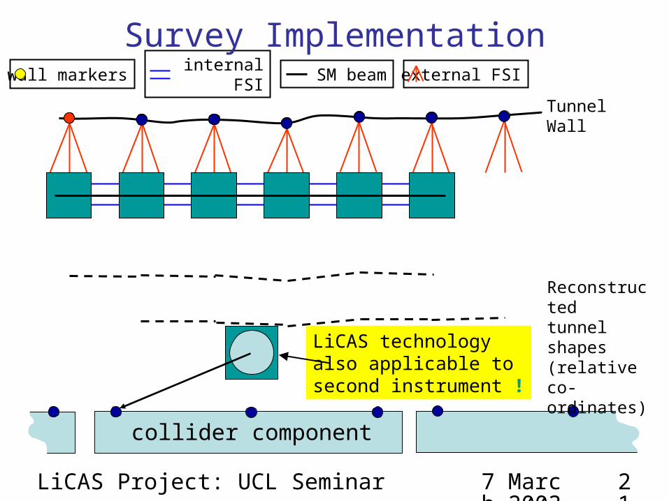
Survey Procedure Two-step Survey procedure
1. Survey equidistant tunnel wall markers via multiple
overlapping measurements: LiCAS Job2. Measure collider components against wall makers:
Advantage:• The same procedure is employed during tunnel
construction, collider installation, operation and maintenance
Accelerator wall
Survey Train
Accelerator
7 March 2003
LiCAS Project: UCL Seminar 17
Survey Train
A survey train is used to perform the first step• Mechanical concept developed by DESY Geodesy Group• LiCAS provides an optical metrology for the train
Survey Train carries two systems• Frequency Scanning Interferometry
− Makes 1D Length Measurements• Laser Straightness Monitors
− Measures transverse displacements and rotations
7 March 2003
LiCAS Project: UCL Seminar 18
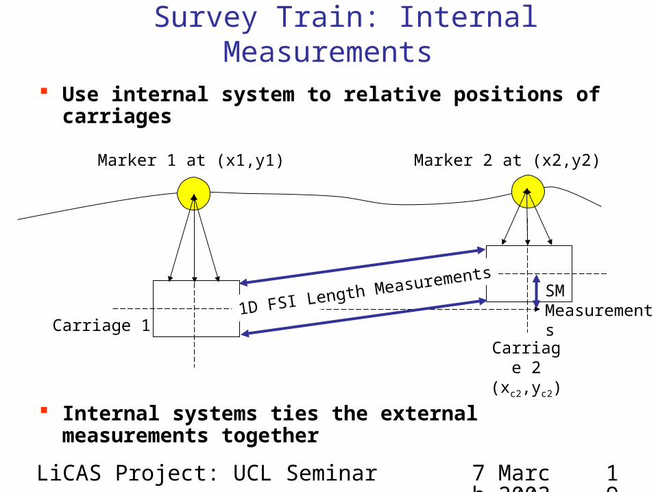
Each carriage measures the position of a reference marker in its own co-ordinates
Q: How to tie reference marker co-ordinates together
Survey Train: External Measurements
Carriage 1
Carriage 2
Marker 1 at (x1,y1) Marker 2 at (x2,y2)
1D FSI Length Measurements
7 March 2003
LiCAS Project: UCL Seminar 19
Use internal system to relative positions of carriages
Internal systems ties the external measurements together
Survey Train: Internal Measurements
Carriage 1Carriage 2
(xc2,yc2)
Marker 1 at (x1,y1) Marker 2 at (x2,y2)
1D FSI Length MeasurementsSM Measurements
7 March 2003
LiCAS Project: UCL Seminar 20
Survey Train: LiCAS Systems
An Optical metrology system for survey of a linear Collider• Fast, automated
LiCAS technologyalso applicable to second instrument !
Survey Implementation
7 March 2003
LiCAS Project: UCL Seminar 22
Frequency Scanning Interferometry Interferometric length measurement technique Require precision of 1m over 5m Originally developed for online alignment of the ATLAS SCT tracker
Tunable Laser
Reference Interferometer: L
Measurement Interferometer: D
Change of phase: GLI
Change of phase: Ref
time
IRef
time
IGLI
(Grid Line Interferometer (GLI))
Ref
GLI
L
D
7 March 2003
LiCAS Project: UCL Seminar 23
FSI: Length MeasurementGLI
Ref
GLI
Ref
GradientD
L
7 March 2003
LiCAS Project: UCL Seminar 24
FSI: Thermal Drift Cancellation
Thermal effects add subtle systematic errors to FSI− Nanometre movements can contribute micron errors (
Use two lasers tuning in opposite directions to cancel thermal drift
Expansion ofInterferometer
I
I
7 March 2003
LiCAS Project: UCL Seminar 25
FSI: Thermal Drift CancellationGLI
Ref
True Gradient
Measured G
radient with
Laser Tuning U
p
Measured Gradient with Laser Tuning Down
7 March 2003
LiCAS Project: UCL Seminar 26
FSI: 2-Laser Thermal Drift Cancellation
m mRange
20 30 40 50 60
417.0
417.4
Laser 1 Laser 2 Com bined
Est
imat
ed G
LI le
ngth
/ m
m
Tim e / h r
2 0 3 0 4 0 5 0 6 0
-4 0
-2 0
0
2 0
4 0
6 0
8 0
Tim e / hr
Warm ing
Coo ling
dT
/dt
(k
s)
-1
7 March 2003
LiCAS Project: UCL Seminar 27
FSI: ATLAS Implementation
7 March 2003
LiCAS Project: UCL Seminar 28
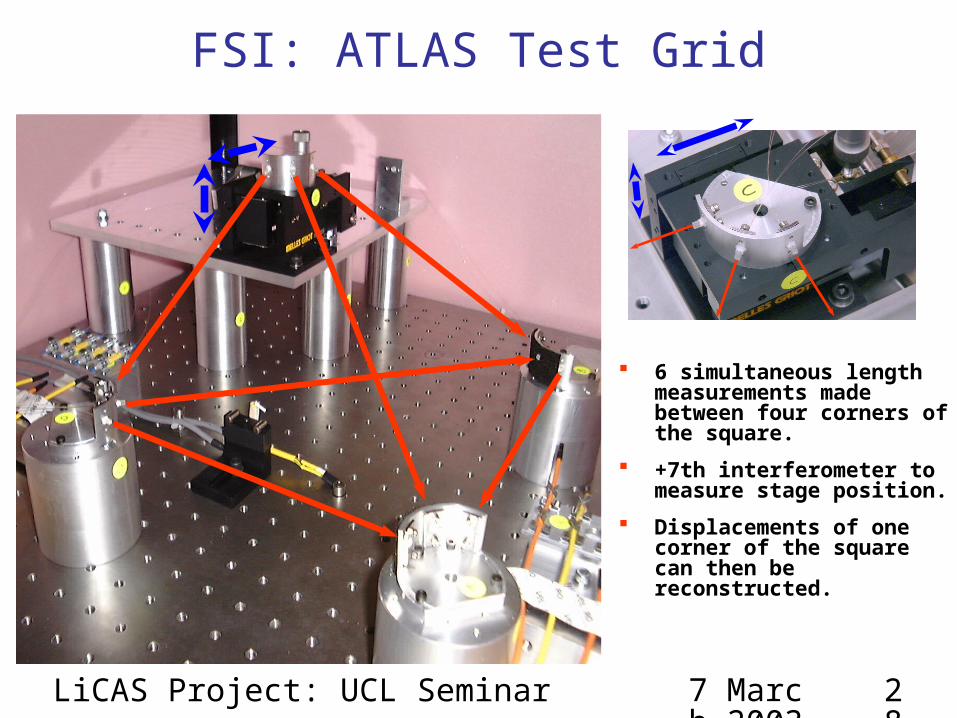
FSI: ATLAS Test Grid
6 simultaneous length measurements made between four corners of the square.
+7th interferometer to measure stage position.
Displacements of one corner of the square can then be reconstructed.
7 March 2003
LiCAS Project: UCL Seminar 29
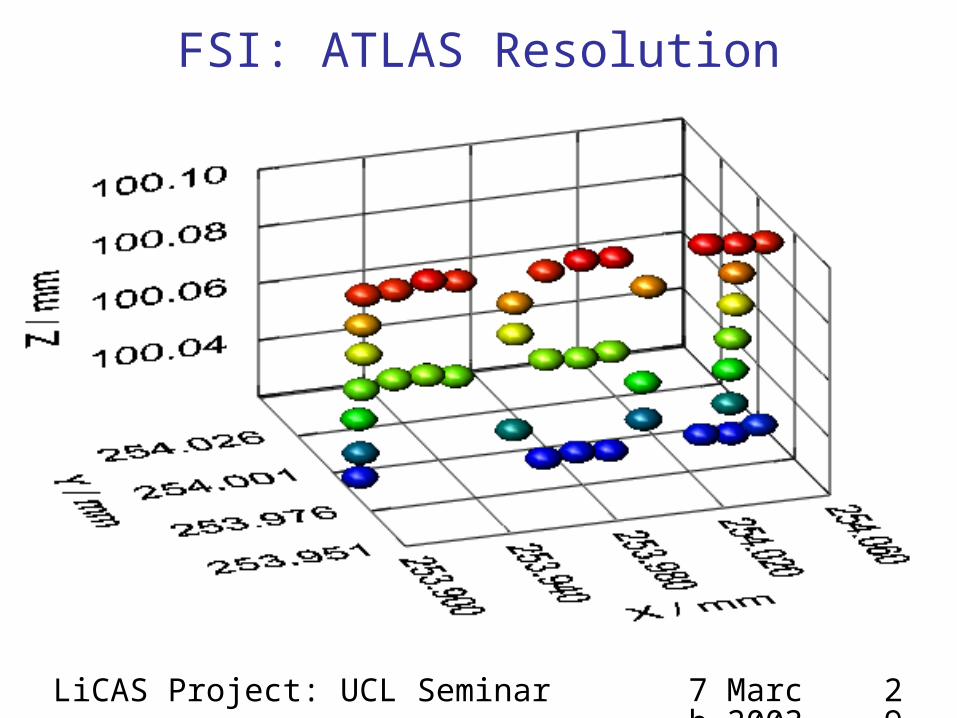
FSI: ATLAS Resolution
7 March 2003
LiCAS Project: UCL Seminar 30
1m
FSI: ATLAS Resolution
Stage is kept stationary
RMS 3D Scatter
< 1 m
Retro Reflector
ATLAS FSI SystemLaser 1
Laser 2
Reference Interferometer
piezodetector
C-Band Amplifier (1520-1570 nm)
L-Band Amplifier (1572-1630 nm)
Splitter Tree
LiCAS FSI System
1m GLI
Uncollimated Quill
APD
Collimated Quill
5m GLIADC
+AMPS
RAM To PC
f1
f2
Amplitude Modulation @ f1
Amplitude Modulation @ f2
Detectors
Demodulator
@ f1 , 1
Demodulator
@ f2 , 2
Demodulator
@ fn , n
7 March 2003
LiCAS Project: UCL Seminar 32
Erbium Doped Fibre Amplifiers EDFA are optical power amplifiers
• Used to amplify low power tunable laser• Standard equipment for Telecoms
− but will it work for FSI ?
Decay
Signal~1550nm
Pump980nm
4I15/2
4I11/2
4I13/2
Incoming Single Photon
Outgoing Photons
fluor
esce
nce
Wavelength / nm 1530 1610
Single Telecoms Channel
7 March 2003
LiCAS Project: UCL Seminar 33
Quill Collimation Refractive
Reflective
Quill end
RetroreflectorCollimation lens
Retroreflector
Reflective, off-axis paraboloid
Quill
7 March 2003
LiCAS Project: UCL Seminar 34
Laser 1
M1
M2
DetectorLaser 2
Demodulator
@ f1 , 1
Demodulator
@ f2 , 1
wa
vele
ng
th
time
1
2
wa
vele
ng
th
time
0
2
Vo
lts
time
Vo
lts
time
t0 t1
t0 t1
Amplitude Modulation @ f1
Amplitude Modulation @ f2
f1
f2
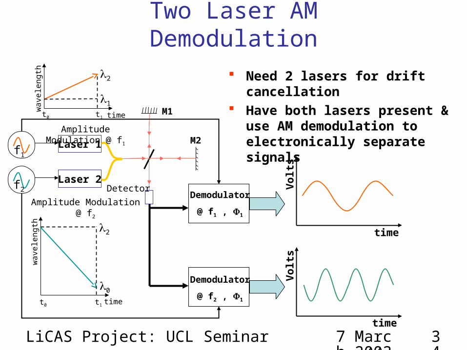
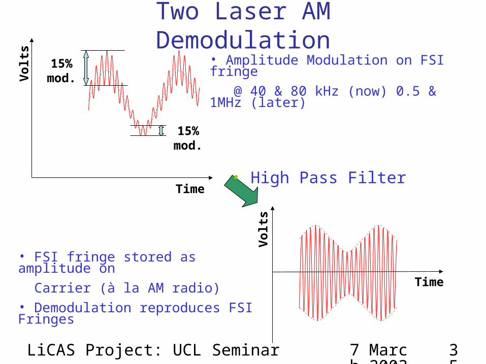
Two Laser AM Demodulation
Need 2 lasers for drift cancellation Have both lasers present & use
AM demodulation to electronically separate signals
7 March 2003
LiCAS Project: UCL Seminar 35
Vol
ts
Time
15% mod.
15% mod.
Time
Vol
ts
• Amplitude Modulation on FSI fringe
@ 40 & 80 kHz (now) 0.5 & 1MHz (later)
• FSI fringe stored as amplitude on
Carrier (à la AM radio)• Demodulation reproduces FSI Fringes
• High Pass Filter
Two Laser AM Demodulation
7 March 2003
LiCAS Project: UCL Seminar 36
Results of Demodulation
Demodulation of modulated laser does not effect interferometer signal
Both signals have same frequency !!
7 March 2003
LiCAS Project: UCL Seminar 37
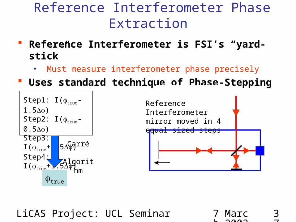
Reference Interferometer Phase Extraction
Reference Interferometer is FSI’s “yard-stick”• Must measure interferometer phase precisely