Spreadsheet Use for Partially Full Pipe Flow Calculations Course No: C03-052 Credit: 3 PDH Harlan H. Bengtson, PhD, P.E. Continuing Education and Development, Inc. 9 Greyridge Farm Court Stony Point, NY 10980 P: (877) 322-5800 F: (877) 322-4774 [email protected]
Transcript
Spreadsheet Use for Partially Full Pipe Flow Calculations Course No: C03-052
Credit: 3 PDH
Harlan H. Bengtson, PhD, P.E.
Continuing Education and Development, Inc. 9 Greyridge Farm Court Stony Point, NY 10980 P: (877) 322-5800 F: (877) 322-4774 [email protected]
Spreadsheet Use for Partially Full Pipe Flow Calculations
Harlan H. Bengtson, PhD, P.E.
COURSE CONTENT 1. Introduction The Manning equation is used for a wide variety of uniform open channel flow, including gravity flow in pipes, the topic of this course. Gravity flow will take place in pipes for partially full flow, up to and including full pipe flow, provided that the pipe isn’t pressurized. Equations are presented and discussed in this course for calculating the cross-sectional area of flow, wetted perimeter, and hydraulic radius for flow of a specified depth in a pipe of known diameter. Also included is a brief review of the Manning equation and discussion of its use to calculate a) the flow rate in a given pipe (diameter, slope, & full pipe Manning roughness) at a specified depth of flow, b) the required diameter for a specified flow rate at a target percent full in a given pipe, c) the normal depth (depth of flow) for a specified flow rate in a given pipe, d) the required pipe slope for a specified flow rate and depth of flow through a given pipe, and d) calculation of an experimentally determined value for the full pipe Manning roughness coefficient. This includes presentation and discussion of the equations for the calculations, example calculations, and screenshots of spreadsheets to facilitate the calculations. Examples include calculation with both U.S. units and S.I. units. 2. Learning Objectives At the conclusion of this course, the student will
• Be able to calculate the cross-sectional area of flow, wetted perimeter, and hydraulic radius for less than half full flow at a given depth in a pipe of given diameter.
• Be able to calculate the cross-sectional area of flow, wetted perimeter, and hydraulic radius for more than half full flow at a given depth in a pipe of given diameter.
• Be able to use Figure 6 in the course material to determine the flow rate at a
given depth of flow in a pipe of known diameter if the full pipe flow rate is known or can be calculated.
• Be able to use Figure 6 the course material to determine the average water
velocity at a given depth of flow in a pipe of known diameter if the full pipe average velocity is known or can be calculated.
• Be able to calculate the Manning roughness coefficient for a given depth of
flow in a pipe of known diameter, with a known Manning roughness coefficient for full pipe flow.
• Be able to use the Manning equation to calculate the flow rate and average
velocity for flow at a specified depth in a pipe of specified diameter, with known pipe slope and full pipe Manning roughness coefficient.
• Be able to calculate the normal depth for a specified flow rate of water
through a pipe of known diameter, slope, and full pipe Manning roughness coefficient
• Be able to calculate the minimum required pipe diameter for a specified flow rate of water through a pipe of known slope, full pipe Manning roughness coefficient and a target value for y/D.
• Be able to calculate the required pipe slope for a specified flow rate of water through a pipe of known diameter, depth of flow, and full pipe Manning roughness coefficient.
• Be able to calculate the value of the full pipe Manning roughness coefficient for a specified flow rate of water through a pipe of known diameter, slope, and depth of flow.
. • Be able to carry out the calculations in the above learning objectives using
either U.S. units or S.I. units.
• Be able to use Excel spreadsheets to make partially full pipe flow calculations.
3. Topics Covered in this Course
I. Manning Equation Review II. Hydraulic Radius - Less than Half Full Flow III. Hydraulic Radius - More than Half Full Flow
IV. Use of Variable n in the Manning Equation
V. Equation for Variable Manning roughness coefficient
VI. Flow Rate and Velocity Calculation
VII. Normal Depth Calculation Review
VIII. Normal Depth for Partially Full Pipe Flow
IX. Calculation of Required Pipe Diameter for Target Value of y/D
X. Calculation of Required Pipe Slope
XI. Calculation of Full Pipe Manning Roughness Coefficient
XII. Summary
XIII. References
4. Manning Equation Review The Manning equation, given below as Equation (1) and Equation (2), is the most widely used equation for uniform open channel flow calculations. Note that the Manning equation is a dimensional equation. That is, the U.S. units given below must be used for the U.S. version of the equation and the S.I. units given below must be used for the S.I. version.
U.S. version: Q = (1.49/n)A(Rh2/3)S1/2 (1)
The parameters in this equation for gravity pipe flow are as follows:
• Q is the volumetric flow rate passing through the channel reach in cfs • A is the cross-sectional area of flow normal to the flow direction in ft2
• S is the bottom slope of the channel** in ft/ft (dimensionless).
• n is a dimensionless empirical constant called the Manning Roughness
coefficient.
• Rh is the hydraulic radius = A/P.
• P is the wetted perimeter of the cross-sectional area of flow in ft. *You may recall that uniform open channel flow (which is required for use of the Manning equation) occurs for a constant flow rate of water through a channel with constant slope, size and shape, and roughness. Uniform and non-uniform flow are illustrated in the diagram on the next page. Uniform partially full pipe flow occurs for a constant flow rate of water through a pipe of constant diameter, surface roughness, and slope. Under these conditions the water will flow at a constant depth and velocity.
Figure 1. Uniform and Non-Uniform Open Channel Flow
**S is actually the slope of the hydraulic grade line. For uniform flow, the depth of flow is constant, so the slope of the hydraulic grade line is the same as the slope of the liquid surface and the same as the channel bottom slope. The channel bottom slope is typically used for S in the Manning equation. It should also be noted that the Manning equation is a dimensional equation. With the 1.49 constant in equation (1), the parameters in the equation must have the units shown in the list below the equation above. For S.I. units, the constant in the Manning equation changes slightly to the following:
Q = (1.00/n)A(Rh2/3)S1/2 (2)
Where:
• Q is the volumetric flow rate passing through the channel reach in m3s. • A is the cross-sectional area of flow normal to the flow direction in m2.
• S is the bottom slope of the channel in m/m (dimensionless).
• n is a dimensionless empirical constant called the Manning Roughness coefficient.
• Rh is the hydraulic radius = A/P.
• P is the wetted perimeter of the cross-sectional area of flow in m.
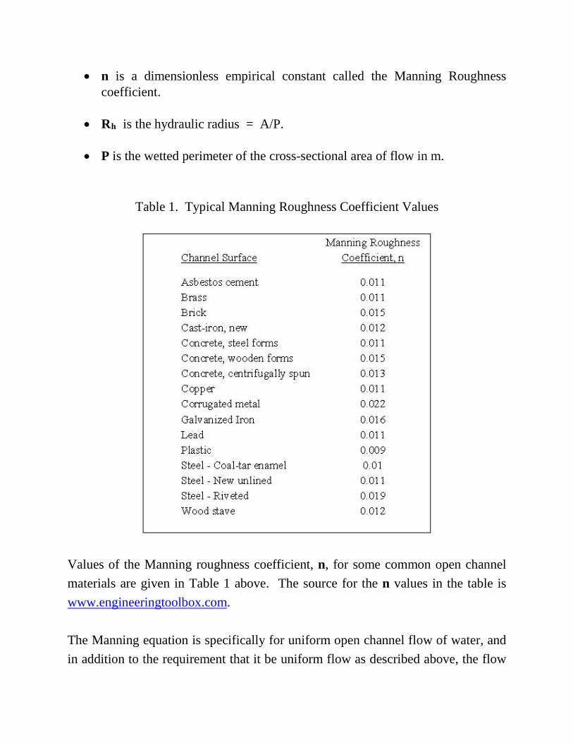
Values of the Manning roughness coefficient, n, for some common open channel materials are given in Table 1 above. The source for the n values in the table is www.engineeringtoolbox.com. The Manning equation is specifically for uniform open channel flow of water, and in addition to the requirement that it be uniform flow as described above, the flow
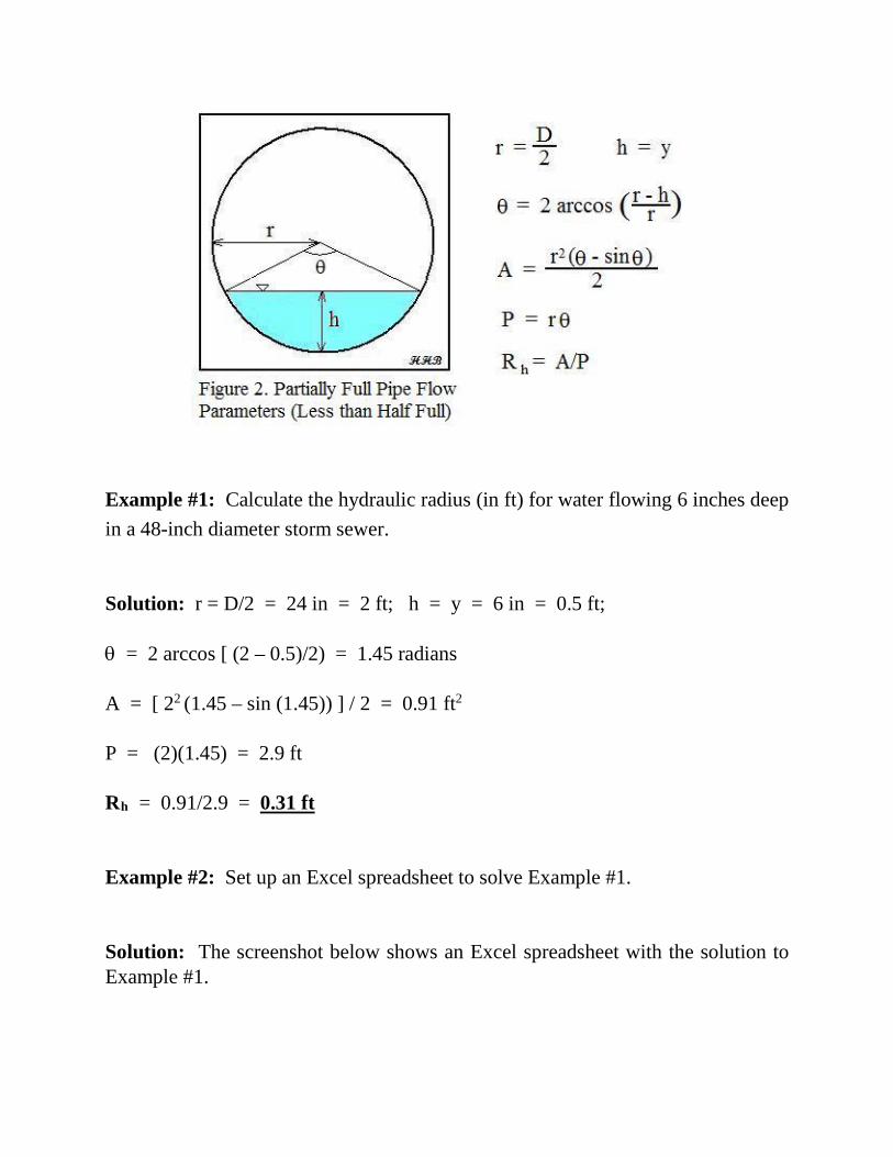
must be steady state flow and it must be turbulent flow in order to use the Manning equation. For steady state flow, there are no changes in velocity patterns or magnitude at any given pipe cross-section. Steady state flow occurs for a constant flow rate of water, while unsteady state flow occurs when there is a fluctuating flow rate of water. Open channel flow is typically laminar if the Reynolds number is less than 500 and it is turbulent if the Reynolds number is greater than 12,500. It may be either laminar or turbulent for Reynolds number between 500 and 12,500, depending on other factors such as the entrance conditions and the roughness of the pipe walls. The Reynolds number for open channel flow is defined as Re = ρVRh/µ, where ρ is the density of the flowing water, µ is the viscosity of the flowing water, V is the water velocity (= Q/A), and Rh is the hydraulic radius as defined above. For practical cases of water flow through a partially full pipe, the flow will almost always be turbulent. In order to be laminar flow, the flow would need to be a very thin layer along the bottom of the pipe. 5. Hydraulic Radius – Less than Half Full Flow The hydraulic radius is one of the parameters needed for Manning equation calculations. Equations are available to calculate the hydraulic radius for known pipe diameter and depth of flow. The equations are slightly different depending on whether the pipe is flowing less than half or more than half full. The calculations for less than half full pipe flow will be covered in this section and the calculations for more than half full flow will be covered in the next section. The equations needed to calculate the cross-sectional area of flow, A, the wetted perimeter, P, and the hydraulic radius, Rh, are shown below, along with a diagram showing the parameters for a pipe flowing less than half full. Note that the parameters r and h are used in the equations for A and P. For this case of less than half full flow, h is simply equal to the depth of flow y, while r is the radius of the pipe, which is D/2.
Example #1: Calculate the hydraulic radius (in ft) for water flowing 6 inches deep in a 48-inch diameter storm sewer. Solution: r = D/2 = 24 in = 2 ft; h = y = 6 in = 0.5 ft; θ = 2 arccos [ (2 – 0.5)/2) = 1.45 radians A = [ 22 (1.45 – sin (1.45)) ] / 2 = 0.91 ft2 P = (2)(1.45) = 2.9 ft Rh = 0.91/2.9 = 0.31 ft Example #2: Set up an Excel spreadsheet to solve Example #1. Solution: The screenshot below shows an Excel spreadsheet with the solution to Example #1.
Figure 3. Screenshot for Hydraulic Radius Calculation – Less Than Half Full The pipe diameter and depth of flow must be entered into the blue cells. Then the spreadsheet calculates the parameters in the yellow cells, using the formulas shown for Example #1, resulting in the same numbers shown in the solution to Example #1, with R = 0.31 ft as the final result. Example #3: Calculate the hydraulic radius (in m) for water flowing 20 mm deep in a pipe of 100 mm diameter. Solution: r = D/2 = 50 mm = 0.050 m; h = y = 20 mm = 0.020 m;
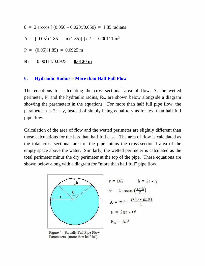
θ = 2 arccos [ (0.050 – 0.020)/0.050) = 1.85 radians A = [ 0.052 (1.85 – sin (1.85)) ] / 2 = 0.00111 m2 P = (0.05)(1.85) = 0.0925 m Rh = 0.00111/0.0925 = 0.0120 m 6. Hydraulic Radius – More than Half Full Flow The equations for calculating the cross-sectional area of flow, A, the wetted perimeter, P, and the hydraulic radius, Rh, are shown below alongside a diagram showing the parameters in the equations. For more than half full pipe flow, the parameter h is 2r – y, instead of simply being equal to y as for less than half full pipe flow. Calculation of the area of flow and the wetted perimeter are slightly different than those calculations for the less than half full case. The area of flow is calculated as the total cross-sectional area of the pipe minus the cross-sectional area of the empty space above the water. Similarly, the wetted perimeter is calculated as the total perimeter minus the dry perimeter at the top of the pipe. These equations are shown below along with a diagram for “more than half full” pipe flow.
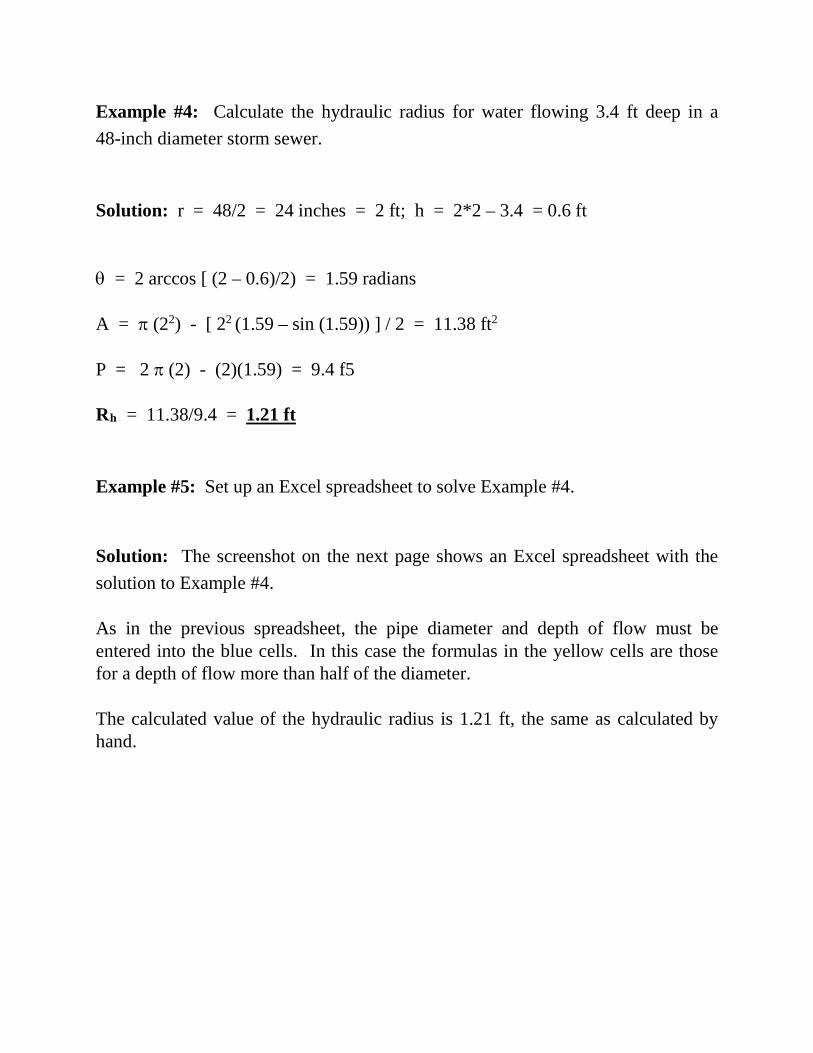
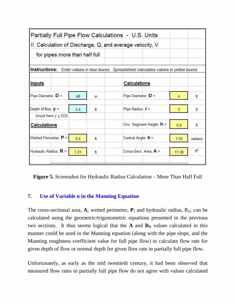
Example #4: Calculate the hydraulic radius for water flowing 3.4 ft deep in a 48-inch diameter storm sewer. Solution: r = 48/2 = 24 inches = 2 ft; h = 2*2 – 3.4 = 0.6 ft θ = 2 arccos [ (2 – 0.6)/2) = 1.59 radians A = π (22) - [ 22 (1.59 – sin (1.59)) ] / 2 = 11.38 ft2 P = 2 π (2) - (2)(1.59) = 9.4 f5 Rh = 11.38/9.4 = 1.21 ft Example #5: Set up an Excel spreadsheet to solve Example #4. Solution: The screenshot on the next page shows an Excel spreadsheet with the solution to Example #4. As in the previous spreadsheet, the pipe diameter and depth of flow must be entered into the blue cells. In this case the formulas in the yellow cells are those for a depth of flow more than half of the diameter. The calculated value of the hydraulic radius is 1.21 ft, the same as calculated by hand.
Figure 5. Screenshot for Hydraulic Radius Calculation – More Than Half Full 7. Use of Variable n in the Manning Equation The cross-sectional area, A; wetted perimeter, P; and hydraulic radius, Rh; can be calculated using the geometric/trigonometric equations presented in the previous two sections. It thus seems logical that the A and Rh values calculated in this manner could be used in the Manning equation (along with the pipe slope, and the Manning roughness coefficient value for full pipe flow) to calculate flow rate for given depth of flow or normal depth for given flow rate in partially full pipe flow. Unfortunately, as early as the mid twentieth century, it had been observed that measured flow rates in partially full pipe flow do not agree with values calculated
as just described above. T. R. Camp developed a method for improving the agreement between measured values of partially full pipe flow rate and values calculated with the Manning equation. He did this by using a variation in Manning roughness coefficient with depth of flow in the pipe as a fraction of the pipe diameter. That is, he used a variation in n/nfull as a function of y/D. His procedure is described in his 1946 article, “Design of Sewers to Facilitate Flow,” which is reference #1 at the end of this course. T. R. Camp’s work led to the graph below, which shows the variation of Q/Qfull, V/Vfull, and n/nfull as functions of the ratio of depth of flow to pipe diameter (y/D). The graph developed by Camp and shown in the diagram below appears in several publications of the American Society of Civil Engineers, the Water Pollution Control Federation, and the Water Environment Federation from 1969 through 1992, as well as in many environmental engineering textbooks. The graph below was prepared from values read off a similar graph in Steel and McGhee’s textbook (reference #5 at the end of this course). Prior to the common use of spreadsheets, which make calculations with the trigonometric/geometric equations for A, P, and Rh, relatively easy, use of the graph below was a widely used method of handling partially full pipe flow calculations. Vfull and Qfull can be calculated for full pipe flow conditions in a given pipe with the Manning equation. Then V and Q can be found for any depth of flow, y, in that pipe by reading values off the graph.
Figure 6. Flow in Partially Full Pipes Although the variation in Manning roughness coefficient, n, shown in the graph above, doesn’t make sense intuitively, it does work well in calculating values of flow rate, velocity, or normal depth that agree with empirical measurements. Keep in mind that the Manning equation was developed for flow in open channels with rectangular, trapezoidal, and similar cross-sections. It works very well for those channel shapes with a constant value for the Manning roughness coefficient, n. For partially full pipe flow, however, using the variation in n with depth of flow, as proposed by Camp, is a preferred method. Example #6: The flow rate and average velocity in a particular 21 inch diameter storm sewer when it is flowing full, have been calculated to be: Qfull = 9.12 cfs and Vfull = 3.79 ft/sec. Estimate the average velocity and flow rate in this storm sewer when it is flowing
a) at a depth of 8.4 inches and b) at a depth of 14.7 inches.
Solution: a) The depth/diameter ratio is: y/D = 8.4/21 = 0.4. From the “Flow in Partially Full Pipes” graph above (Figure 6), at y/D = 0.4: V/Vfull = 0.7 and Q/Qfull = 0.25. The flow rate and average velocity at y = 8.4 inches can now be calculated as follows: V = (V/Vfull)(Vfull) = (0.7)(3.79) ft/sec = 1.95 ft/sec Q = (Q/Qfull)(Qfull) = (0.25)(9.12) cfs = 2.28 cfs b) The depth/diameter ratio is: y/D = 14.7/21 = 0.7. From the “Flow in Partially Full Pipes” graph above (Figure 6), at y/D = 0.7: V/Vfull = 0.95 and Q/Qfull = 0.7. The flow rate and average velocity at y = 14.7 inches can now be calculated as follows: V = (V/Vfull)(Vfull) = (0.95)(3.79) ft/sec = 2.65 ft/sec Q = (Q/Qfull)(Qfull) = (0.7)(9.12) cfs = 6.38 cfs 8. Equation for Variable Manning Roughness Coefficient Although the “Flow in Partially Full Pipes” graph can be used to determine average velocity and flow rate for partially full pipe flow, as shown in Example #6, it would often be convenient to be able to make such calculations with an Excel spreadsheet. Equation (3) below allows that to be done. This equation fits the
graph of n/nfull as a function of y/D as shown in Figure 6. The source for Equation (3) is Reference #7 at the end of the course. n/nfull = 1 + (y/D)0.54 - (y/D)1.20 (3) Example #7: Water is flowing through a 12" diameter corrugated metal pipe at a depth of 4 inches. The Manning roughness coefficient for full pipe flow in the corrugated metal pipe is: nfull = 0.022. Calculate the Manning roughness coefficient, n, for the 4" deep flow in this pipe. Solution: The given parameters are depth of flow, y = 4 inches, and pipe diameter, D = 12 inches. Thus y/D = 4/12 = 0.3333. Substituting y/D into Equation (3) gives: n = 0.022[1 + 0.33330.54 - 0.33331.20] n = 0.028 The calculation of n for given values of D, y, and nfull, can conveniently be done with an Excel spreadsheet, once the formulas have been entered into the spreadsheet. Example #8: Set up an Excel spreadsheet to solve Example #7. Solution: The screenshot on the next page shows an Excel spreadsheet with the solution to Example #7. If the diameter, D; depth of flow, y; and full pipe flow value for the Manning roughness coefficient, nfull, are entered in the blue cells, the spreadsheet calculates
y/D, n/nfull, and finally the value of n for that depth of flow. The screenshot shows the solution, giving the same result as that calculated in Example #7: n = 0.028.
Figure 7. Screenshot for Calculation of n/nfull and n for given y/D
9. Flow Rate and Velocity Calculation The cross-sectional area, A; wetted perimeter, P; and hydraulic radius, Rh, can be calculated for known pipe diameter and depth of flow using the equations that were presented and discussed in Section 5 (for less than half full flow) or in Section 6 (for more than half full flow). Equation (6) can be used to calculate the Manning
roughness coefficient, n, for given nfull, y, and D. These values together with the pipe slope, S, can be used in the Manning equation to calculate the flow rate and velocity, as illustrated in the following example. Example #9: Calculate the flow rate and average velocity for the 4" deep flow in the 12" diameter corrugated metal pipe from Example #7, if the pipe slope is 0.0085. Solution: From the equations in section 5: r = D/2 = 12/2 inches = 6 inches = 0.5 ft h = y = 4 inches = 0.3333 ft θ = 2 arccos [ (r - h)/r ] = 2 arccos [ (0.5 - 0.3333)/0.5 ] = 2.462 radians A = r2(θ - sinθ)/2 = (0.52)[2.462 - sin(2.462)]/2 = 0.2292 ft2 P = rθ = (0.5)(2.462) = 1.231 ft Rh = A/P = 0.2292/1.231 = 0.1862 ft From Example #7: n = 0.028 Now the Manning equation can be used to calculate Q: Q = (1.49/n)A(Rh
2/3)S1/2 = (1.49/0.028)(0.2292)(0.18622/3)(0.00851/2) Q = 0.364 cfs V = Q/A = 0.367/0.2292 = 1.59 ft/sec As expected, this problem can be solved using an Excel spreadsheet. The screenshot on the next page shows an Excel spreadsheet with the solution to
Example #9. Using entered values for pipe diameter, D, depth of flow, y, the hydraulic radius is calculated by the spreadsheet as in Examples #1, 2, 3, 4, & 5. With the given values for D and y, together with the value for nfull, calculation of n/nfull and n is carried out as in Examples #7, 8, & 9. Finally, the above values together with the specified value for the pipe slope, S, are used in the Manning equation to calculate the flow rate, Q, and average velocity, V, in the pipe. This results in the same values for Q and V calculated in Example #9, Q = 0.364 cfs and V = 1.59 ft/sec. Example #10 illustrates a similar calculation using S.I. units. Example #10: Calculate the flow rate and average velocity for water flow 20 mm deep in a 100 mm diameter corrugated metal pipe (nfull = 0.022), if the pipe slope is 0.0085. Solution to Example 10: From the equations in section 5: r = D/2 = 100/2 mm = 50 mm = 0.05 m h = y = 20 mm = 0.02 m θ = 2 arccos [ (r - h)/r ] = 2 arccos [ (0.05 - 0.02)/0.05 ] = 1.854 radians A = r2(θ - sinθ)/2 = (0.052)[1.854 - sin(1.854)]/2 = 0.001117 m2 P = rθ = (0.05)(1.854) = 0.0927 m Rh = A/P = 0.001117/0.0927 = 0.01205 m
Figure 8. Screenshot for Calculation of Q and V for partially Full Pipe Flow For y/D = 20/100 = 0.2, from Eqn (3): n/nfull = [1 + 0.20.54 - 0.21.20] = 1.27 Now the Manning equation can be used to calculate Q:
Q = 0.000193 m3/s V = Q/A = 0.000193/0.001117 = 0.173 m/sec If the depth of flow is more than half of the pipe diameter, the calculation of flow rate and velocity will be the same as in the last two examples, except that the cross-sectional area, A; wetted perimeter, P; and hydraulic radius, Rh, will be calculated for the known pipe diameter and depth of flow using the equations that were presented and discussed in Section 6. Example #11: Calculate the flow rate and average velocity for 10" deep flow in the 12" diameter corrugated metal pipe from Example #7, if the pipe slope is 0.0085. Solution: From the equations in section 6: r = D/2 = 12/2 inches = 6 inches = 0.5 ft h = 2r - y = (2)(0.5) - 10/12 = 0.1667 ft θ = 2 arccos [ (r - h)/r ] = 2 arccos [ (0.5 - 0.1667)/0.5 ] = 1.682 radians A = πr2 - r2(θ - sinθ)/2 = π0.52 - (0.52)[1.682 - sin(1.682)]/2 = 0.6994 ft2 P = 2πr - rθ = 2*pi()*0.5 - (0.5)(1.682) = 2.300 ft Rh = A/P = 0.6994/2.300 = 0.3040 ft From Equation (3): n = 0.022[1 + (10/12)0.54 – (10/12)1.2] = 0.024 Now the Manning equation can be used to calculate Q: Q = (1.49/n)A(Rh
Q = 1.79 cfs V = Q/A = 1.55/0.6994 = 2.56 ft/sec 10. Review of Normal Depth Calculation For a constant flow rate through a channel with constant bottom slope, cross-sectional shape and size, and Manning roughness coefficient, the depth of flow will be constant at a depth called the normal depth. The procedure for determining the normal depth is the same for gravity flow through partially full pipes as it is for open channel flow with cross-sectional shapes like rectangular or trapezoidal. The normal depth can be determined by rearranging the Manning equation to: A(Rh
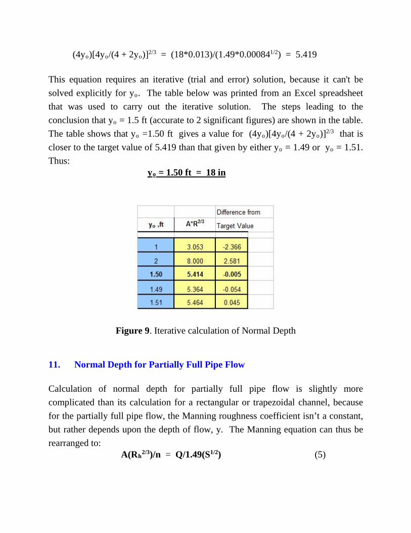
2/3) = Qn/1.49(S1/2) (4) For flow in a channel with specified Q, n, and S, the right side of the equation has a constant value that can be calculated. The left side of the equation can be written as a function of depth of flow, y, for specified channel shape and size. An iterative solution is typically required to find the value of y that makes the two sides of the equation equal. This type of calculation is illustrated in Example #12 below. Example #12: Determine the normal depth for water flowing at a rate of 18 cfs in a rectangular channel that has a bottom slope of 0.00084, bottom width of 4 ft, and Manning roughness coefficient of 0.013. Solution: For the given rectangular channel: A = byo = 4yo, P = b + 2yo = 4 + 2yo, and Rh = A/P = 4yo/(4 + 2yo) Substituting values and expressions into Equation (4), the rearranged Manning equation, gives:
(4yo)[4yo/(4 + 2yo)]2/3 = (18*0.013)/(1.49*0.000841/2) = 5.419 This equation requires an iterative (trial and error) solution, because it can't be solved explicitly for yo. The table below was printed from an Excel spreadsheet that was used to carry out the iterative solution. The steps leading to the conclusion that yo = 1.5 ft (accurate to 2 significant figures) are shown in the table. The table shows that yo =1.50 ft gives a value for (4yo)[4yo/(4 + 2yo)]2/3 that is closer to the target value of 5.419 than that given by either yo = 1.49 or yo = 1.51. Thus:
yo = 1.50 ft = 18 in
Figure 9. Iterative calculation of Normal Depth 11. Normal Depth for Partially Full Pipe Flow Calculation of normal depth for partially full pipe flow is slightly more complicated than its calculation for a rectangular or trapezoidal channel, because for the partially full pipe flow, the Manning roughness coefficient isn’t a constant, but rather depends upon the depth of flow, y. The Manning equation can thus be rearranged to: A(Rh
2/3)/n = Q/1.49(S1/2) (5)
The right side of this equation is constant and the left side is a function of the normal depth, yo, so iterative solution of this equation can be used instead of equation (4) to determine the normal depth for partially full pipe flow. Example #13: Find the depth of flow (normal depth) for 0.2 cfs of water flowing through a 12 inch diameter concrete pipe (nfull = 0.013) with a pipe slope of 0.0085. Solution: The given parameters are: D = 12 inches, Q = 0.2 cfs, S = 0.0085, and nfull = 0.013. The right side of equation (4) is:
Q/1.49(S1/2) = 0.2/(1.49*0.00851/2) = 1.456
The equations needed to calculate A(Rh
2/3)/n for a given value of yo are: r = D/2, and n/nfull = 1 + (y/D)0.54 – (y/D)1.2 and for y < D/2: h = y, θ = 2 arccos[(r – h)/r], A = r2(θ – sinθ)/2, and P = rθ, or for y > D/2: h = 2r - y, θ = 2 arccos[(r – h)/r], A = πr2 - r2(θ – sinθ)/2, and P = 2πr - rθ, r = D/2, The iterative solution can be done by hand to find the value of yo that makes A(Rh
2/3)/n equal to 1.456 to the degree of accuracy desired. However, the use of a spreadsheet makes the repetitive calculations much easier. Figure 10 is a screenshot of an Excel spreadsheet set up to solve Example #13. It uses IF statements (based on whether y is less than or greater than D/2) to calculate values
for θ, A, and P. It uses Excel’s “Goal Seek” tool to carry out the iterative solution, and shows the solution: yo = 0.188 ft = 2.25 in
Fig. 10. Screenshot of a Spreadsheet showing the solution to Example #13 12. Calculation of Required Pipe Diameter for a Target Value of y/D
The equations used for calculating the required pipe diameter for a target value of y/D are the same as those discussed and illustrated with examples for calculation of flow rate and velocity or normal depth in sections 9 and 11. An iterative solution, similar to that used to calculate normal depth, is needed for this calculation. For this case, also, the Manning equation is rearranged to the form: A(Rh
2/3)/n = Q/1.49(S1/2) The right side of this equation can be calculated from the specified values of Q and S. The iterative solution consists of selecting a value of D and calculating a value for the left side of the equation. This needs to be repeated until the left side of the equation is equal to the right side of the equation. Although this sounds rather straightforward, each iteration requires quite a few calculations. After assuming a value for D, the following calculations are needed.
y = (y/D)D r = D/2
If y < r, h = y If y > r, h = 2r – y
θ = 2 arccos[(r – h)r]
If y < r, A = r2(θ – sinθ)/2 If y > r, A = πr2 – r2(θ – sinθ)/2
After completing all of the above calculations, the value of (A*Rh2/3)/n can be
calculated to compare with the target value for that quantity. The whole process needs to be repeated until the calculated value of (A*Rh
2/3)/n is equal to the target value to the desired degree of accuracy. This is rather cumbersome to do by hand,
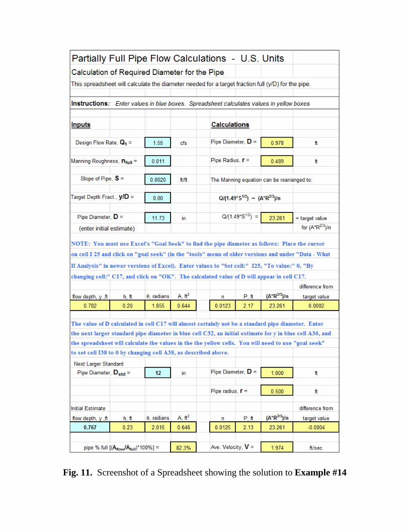
but it can be done quite conveniently with a spreadsheet as illustrated in Example #14 below. Example #14: Determine the diameter required for steel pipe (nfull = 0.011), at a slope of 0.002, carrying 1.55 cfs with a target y/D of 0.8. Solution: Figure 11 shows a spreadsheet screenshot with the solution to this example. The required inputs are shown in the blue cells as follows: design flow rate, Q; Manning roughness coefficient, nfull; pipe slope, S; the target value for y/D; and an initial estimate for the pipe diameter, D, in inches. The spreadsheet calculates the pipe diameter and radius in feet and calculates the value of Q/(1.49S1/2), which is the target value for (A*Rh
2/3)/n. The spreadsheet has a row of yellow cells with the formulas for the calculations shown above for the iterative solution. Carrying out the Excel “Goal Seek” process (as described on the spreadsheet) results in the initial estimate for pipe diameter being replaced the the calculated required minimum diameter. In this example, the required minimum diameter is 11.65 inches. The calculated required minimum diameter will almost certainly not be a standard pipe size, as noted in the comment on the spreadsheet. Thus, the last part of the spreadsheet shown, is calculation of the actual depth of flow, % full for the pipe area, and average velocity for the next larger standard pipe size, which for this example is 12 inches. Nominal diameters for standard U.S. pipe sizes ranging from 1/8 inch to 60 inches are as follows: 1/8, 1/4, 3/8, 1/2, 3/4, 1, 1 ¼, 1 ½, 2, 2 ½, 3, 4, 6, 8, 10, 12, 14, 16, 18, 20, 22, 24, 26, 28, 30, 32, 36, 40, 42, 44, 48, 52, 56, 60
Fig. 11. Screenshot of a Spreadsheet showing the solution to Example #14
Example #14 shows the calculation of minimum required pipe diameter for a case in which the target y/D is greater than 0.5. Calculations for a case in which the target y/D is less than 0.5, would be essentially the same, but would the equations used for h, Q, A, P, Rh, and n would be those for less than half full partially full pipe flow. The calculations for S.I. units would be the same as those just illustrated in Example #14, using the following units: Q in m3/s, A in m2, P in m, and Rh in m. Also, as noted previously, the constant in the Manning equation is 1.00 for S.I. units, instead of 1.49, so the rearranged form of the equation for use in the iterative calculations to determine required diameter is:
Q/(1.00*S1/2) = (A*Rh2/3)/n
Nominal diameters for standard S.I. pipe sizes ranging from 6 mm to 1500 mm are as follows: 6, 8, 10, 15, 20, 25, 32, 40, 50, 65, 80, 100, 150, 200, 250, 300, 350, 400, 450, 500, 550, 600, 650, 750, 800, 900, 1000, 1050, 1100, 1200, 1300, 1400, 1500 13. Calculation of Required Pipe Slope The required pipe slope can be calculated for specified pipe diameter, D; pipe flow rate, Q; depth of flow, y; and full pipe Manning roughness coefficient, nfull. The calculations will proceed in a manner very similar to those used for the other parameters in previous sections. In this case an iterative calculation is not needed, because the Manning equation can be solved for S in terms of the specified parameters listed above. When solved for S, the Manning equation becomes:
S = {Qn/[1.49A(Rh2/3)]}2 for U.S. units, and:
S = {Qn/[1.00A(Rh
2/3)]}2 for S.I. units The next example illustrates the calculation of required pipe slope for partially full pipe flow. Example #15: Determine the required pipe slope for water flowing at 2.3 cfs with a 6 inch depth of flow through a 48 inch diameter pipe that has a Manning roughness coefficient of nfull = 0.012. Solution: Figure 12 below shows a screenshot of a spreadsheet solution for this example. As shown in the screenshot, the given input values were entered in the four blue cells in the upper left part of the screenshot. The values in all of the other yellow cells were calculated by the spreadsheet. The calculation of the circular segment height, h, the cross-sectional area of flow, A, and the wetted perimeter, P, use IF statements to make the calculations, because the equations to be used for these parameters are different depending on whether it is less than half full or greater than half full flow. The rest of the calculated cells are straightforward use of the equations that have been presented and used in previous sections. The calculated value of the required pipe slope is 0.0030 ft/ft.
Fig. 12. Screenshot of a Spreadsheet showing the solution to Example #15
14. Calculation of Full Pipe Manning Roughness Coefficient The value of the full pipe Manning roughness coefficient can be calculated for specified pipe diameter, D; pipe flow rate, Q; depth of flow, y; and pipe slope, S. The calculations will proceed in a manner very similar to those used for the other parameters in previous sections. In this case an iterative calculation is not needed, because the Manning equation can be solved for n in terms of the specified parameters listed above. When solved for n, the Manning equation becomes: n = (1.49/Q)A(Rh
2/3)S1/2 for U.S. units, and: n = (1.00/Q)A(Rh
2/3)S1/2 for S.I. units The next example illustrates the calculation of the full pipe Manning roughness coefficient for partially full pipe flow. Example #16: Calculate the full pipe Manning roughness coefficient for a pipe if water flows at 0.065 m3/s, with a 150 mm depth of flow, through a 1200 mm diameter pipe with a slope of 0.0028. Solution: Figure 13 below shows a screenshot of a spreadsheet solution for this example. As shown in the screenshot, the given input values were entered in the four blue cells in the upper left part of the screenshot. The values in all of the other yellow cells were calculated by the spreadsheet. The calculation of the circular segment height, h, the cross-sectional area of flow, A, and the wetted perimeter, P, use IF statements to make the calculations, because the equations to be used for these parameters are different depending on whether it is less than half full or greater than half full flow. The rest of the calculated cells are straightforward use of the equations that have been presented and used in previous sections. The calculated value of the Manning roughness coefficient at the specified flow
conditions is 0.0137. For y = 150 mm and D = 1200 mm, y/D = 150/1200 = 0.125. n/nfull can thus be calculated as: n/nfull = 1 + 0.1250.54 – 0.1251.20 = 1.24 Thus, nfull = n/(n/nfull) = 0.0137/1.24 = 0.0111
Fig. 13. Screenshot of a Spreadsheet showing the solution to Example #16
15. Summary Calculation of flow rate and average velocity, or determination of normal depth at a given flow rate, for partially full pipe flow can be carried out with the Manning equation in a manner similar to such calculations for traditional open channel cross-sections, like rectangular or trapezoidal. Calculations for partially full pipe flow are complicated by two factors: i) the equations for calculating A, P and Rh are somewhat more complicated and ii) the Manning roughness coefficient must be considered to vary as a function of the ratio of depth of flow to diameter (y/D) in order to make accurate calculations. The equations needed and example calculations for partially full pipe flow are presented and discussed in this course. 16. References
1. Camp, T.R., “Design of Sewers to Facilitate Flow,” Sewage Works Journal, 18 (3), 1946
2. Chow, V. T., Open Channel Hydraulics, New York: McGraw-Hill,
1959.
3. Steel, E.W. & McGhee, T.J., Water Supply and Sewerage, 5th Ed., New York, McGraw-Hill Book Company, 1979
4. ASCE, 1969. Design and Construction of Sanitary and Storm
Sewers, NY
5. Goswami, I., Civil Engineering All-in-One PE Exam Guide: Breadth and Depth, 2nd Ed, Eqn 303.32) McGraw-Hill, NY, NY, 2012.
6. Bengtson, Harlan H., Partially Full Pipe Flow Calculations Spreadsheets, available as a paperback book or as an Amazon Kindle e-book.
7. Bengtson, Harlan H., “Partially Full Pipe Flow Calculations with Excel Spreadsheets.” An online article at: www.EngineeringExcelSspreadsheets.com
8. Bengtson, Harlan H., Uniform Open Channel Flow and The Manning
Equation, an online, continuing education course for PDH credit.