224
| Date post: | 08-Nov-2014 |
| Category: |
Documents |
| Upload: | chaitanya-raj-goyal |
| View: | 108 times |
| Download: | 3 times |


44 The Masterbuilder - September 2012 • www.masterbuilder.co.in
Solving Problems Caused by Moisture Vapor Transmission on Concrete Floors
Water, or more precisely water vapor, passing through a concrete slab on grade can cause the loss of adhesion, warping, peeling, unacceptable appearance of resilient floor coverings, and bubbles or efflorescence deposits beneath seamless flooring. While we are specifically discussing polymer type coatings and surfacings on concrete in this paper, any impermeable floor covering is detrimentally affected by moisture vapor transmission.
Moisture Migration
Excessive moisture in concrete slabs on grade usually originates from one or more sources:1
- Residual water in or below the slab remaining from the construction process
- Naturally occurring ground water from a permanent or seasonal high water table
- Water from irrigation systems, broken plumbing pipes, or other man-made sources
A slab may appear dry, but actually have a deleterious level
of moisture vapor passing through it. Moisture passing through the slab can carry alkaline salts from the ground or the concrete itself. According to authorities on the subject, the time required for slabs to dry out sufficiently so that floor coverings and finishes are not adversely affected ranges from four weeks to six months.
Excess moisture in or below the concrete slab is the cause for a large percentage of coating failures on concrete. While moisture in concrete during the application of a floor surfacing is an important criterion, it is not the ultimate cause of failure months or years later. Many epoxy materials can tolerate and bond to a concrete slab with a relatively high moisture content. It is the flow of moisture or moisture vapor, better described as moisture vapor transmission, that causes most adhesion problems. There are also reported cases of bond failures on above grade slabs, but almost all are related to moisture vapor transmission rather than moisture content. A good example would be an above grade concrete slab poured on a metal deck with no vents. Excess water pools on the metal deck and slowly comes to the surface as
Understanding the cause of moisture related bond failures on concrete surfaces is important in finding a solution. Failures can be vastly reduced with proper testing, evaluation, and surface treatment.
Vapor Pressure of Moisture in Air at Different Temperatures & Relative Humidities (RH) [from Concrete Construction/June 1996]Figure A: The driving force for moisture movement through a slab is the differential in vapor pressure between the above slab and below-slab environments. Use this graph to determine the vapor pressure of moisture in air at different temperatures and reletive humidity.
Flooring Vapor Transmission
Robert R. CainFounder, KRC Associate, Batavia, Ohio

www.masterbuilder.co.in • The Masterbuilder - September 2012 45
moisture vapor. The real area of greatest concern is slabs-on-grade and how to dry out and/or minimize the vapor transmission.
Although the curing process of concrete consumes water, it is only the first step in the drying process. This process depends on the relative humidity and temperature environ-ment inside the building, which in turn influences the rate of vapor transmission through and out of the concrete.
Vapor transmission depends on the vapor pressure of air. The vapor pressure difference between air in voids of the concrete and the air above the slab will in part determine the vapor transmission rate.
The vapor pressure of air can be determined from figure A if the relative humidity and temperature are known.2 To dry a slab, for example, the movement of moisture must be from the concrete to the air. If the environment at the bottom of the concrete has a relative humidity of 100 percent and temperature of 21°C (70°F), the vapor pressure of air within concrete will be about 2.48 kPa (0.36 psi). If the relative humidity and temperature inside the room are 60 percent and 27°C (80°F) respectively, air vapor pressure will be 2 kPa (0.29 psi).
High pressure moves to low pressure, so the pressure difference of 0.48 kPa (0.07 psi) is the driving force of moist air moving from the concrete to the room. Moisture passing through the slab can carry alkaline salts from the ground or the concrete itself. These salts will precipitate at the surface causing an upward force at the bond line. To forcedry the concrete, it is more desirable to lower the relative humidity in the room than to just raise the temperature. If any of the above conditions exist after the floor covering is installed, then the moisture becomes trapped under the covering and condenses.
Measuring Moisture Transmission
There are a multitude of tests used to establish moisture content and moisture vapor transmission.3 These include the Plastic Sheet Test (ASTM D-4263), Calcium Chloride Test, Gravimetric Testing, Radio Frequency Test, Nuclear Density Test, and Electro-Conductive Testing (moisture meter). Most of these tests are designed to determine the moisture content or locate areas of excessive moisture. Only two, however, determine the transmission of moisture. The Plastic Sheet Test (ASTM D-4263) will give a qualitative, wet/not wet answer and the Calcium Chloride Test (ASTM F- 1869-98) will provide a quantitative value.
The Calcium Chloride Test (ASTM F1869-98) uses a small dish of calcium chloride under an impermeable clear cover. By weighing the dish before and after a seventy-two hour exposure, you can quantify the amount of moisture flow in pounds per 1,000 ft² per 24 hours (kg per 90 m² per
24 hours). A value of 3 lbs. (1.4 kg) or less is believed to be acceptable to most flooring and coating manufacturers. Values on extremely wet floors have been recorded showing greater than 10 lbs. per 1,000 ft² per 24 hours (4.5 kg per 90 m² per 24 hours).
It is important to understand the difference between moisture vapor transmission and moisture content. You may have low moisture content and have a bond failure at some point in the future due to moisture vapor transmission through the slab. High moisture content in the slab will usually not cause a problem unless conditions are right to cause movement of that moisture to the surface. So it is moisture transmission to the surface, whether it is from high moisture content in the slab or under the slab, that causes the problem.
Water, more importantly, water vapor, will migrate to the surface when there is a higher vapor pressure in the concrete than in the air above the surface. In many cases, testing for moisture vapor transmission on new buildings is done prior to enclosing the building to allow the flooring contractor to proceed. Since the building is not enclosed, the conditions above the slab are similar to the slab itself and there is little moisture attraction to the surface and the test reads dry (less than 3 lbs. based on the calcium chloride test). When the building is enclosed, the air conditioning lowers the humidity and the temperature, which lowers the vapor pressure causing a gradient and creating a vapor drive.
The original theory on bond failures was that loss of bond was due to hydrostatic pressure caused by the vapor drive. However, this pressure is not caused by hydrostatic pressure. This pressure is caused by the upward movement of metal salts that gather at the surface and form silicates such as calcium and potassium in a typical alkali-silica reaction. All ingredients of such a reaction are present: amorphous silica, calcium hydroxide (lime), and moisture. Such reactions can cause pressures up to 1,500 psi, more than enough to cause bond failures in floor surfacings. By changing this combination, the pressures (and failures) are less common. Controlling the moisture migration is the best choice.
Controlling Moisture Transmission
The best way to control moisture vapor transmission is right at the beginning, from the subsoil to the concrete placement. When installing slabs-on-grade that are to receive an impermeable (non-breathing) coating or surfacing, an efficient vapor barrier must be used beneath the concrete.
The placement of a vapor barrier is also important. The American Concrete Institute (ACI) is vague about the ground moisture conditions requiring vapor barrier use.
Flooring Vapor Transmission

46 The Masterbuilder - September 2012 • www.masterbuilder.co.in
Section 302.IR-96, subsection 3.2.3 discusses the use of vapor retarders (barriers) and recommends the vapor retarder be placed under a minimum of 4 in. (100 mm) of compactible, granular fill (Section 4.1.5).4 This is done to assist in the curing of the slab.
If a vapor barrier is installed in this manner (under a granular fill), an extended period of time (much longer than thirty days and in some cases over a year) is required to dry adequately enough for an impermeable coating to be used on the surface.
When using an efficient vapor barrier to control moisture vapor transmission, it should be placed directly under the slab and be more efficient than sixmil poly, which is easily punctured during concrete placement. ACI 302.IR-96 now recommends that a minimum of 10 mils (0.25mm) be used. Once the vapor barrier has been chosen and is in place, a good quality concrete and good placement techniques are important. A low water to cement ratio (0.45 max), designed for high compressive strength and low permeability, are important. A wellplaced and properly-cured concrete slab will provide a hard, dense concrete surface of low permeability. The following job site conditions will minimize the excessive moisture transmission of a slab-on-grade:
- Place concrete directly over an efficient vapor barrier (greater than six-mil poly and puncture resistant).
- Use low water to cement ratios in the concrete mix (0.45 max) and 4 in. maximum slump.
- Adequately cure the slab for maximum surface strength and low permeability.
- Perform moisture transmission tests using the Calcium Chloride Test (ASTM F-1869-98) to quantify the degree of moisture transmission. Simulate in-use conditions of the building when running these tests. Only under a controlled environment will this test be meaningful.
Repairing Failures
The problem of moisture vapor transmission in concrete slabs on or below grade has been a recognized condition for many years. Called by a variety of names, such as hydrostatic pressure, osmosis, and capillary action, the problem is finally being defined properly to focus on solutions short of removing the concrete slab and starting over.
Several companies offer warranted treatments to the surface that are aimed at reducing or eliminating the problem. Floor coating manufacturers are also offering treatments to go under their systems for prevention of bond failure.
Some treatments that have shown promise are:
- A common remedy and repair is to use a breathable system, which allows the passage of moisture vapor
without interfering with the bond. These systems are typically some form of modified cementitious material.
- The use of penetrating primers and hardeners, which reduce the rate of moisture transmission, are effective if the initial transmission rates are not excessively high. In these cases, as in all scenarios, testing along the way is important. The three-pound per one thousand square feet per twentyfour hour figure is the goal.
- Semipermeable membranes are being used to reduce the moisture rate below three pounds. These systems are composed of a fiberglass mat or membrane impregnated with a resinous binder. The composition acts as a wick to diffuse moisture and prevent a build-up of salts. The membrane allows the moisture to be distributed laterally. Condensed moisture is also trapped and allowed to absorb back into the concrete as a liquid.
- Multiple phase systems are also being designed to reduce moisture vapor transmission in concrete. These systems use multiple applications of material which gradually reduces porosity and increases density in the concrete surface. This is followed by successive layers of semipermeable slurries which reduces vapor transmission to an acceptable level.
Conclusion
The problem of moisture in and under a concrete slab-on-grade is a problem of vapor transmission through the slab. The attraction or flow of moisture to the surface is the normal flow from a point of high vapor pressure to a point of low vapor pressure to create equilibrium. By controlling or lessening the rate of moisture transmission in slabs-on-grade, we can successfully use impermeable systems on these surfaces.
Once a moisture transmission problem is identified, it requires considerable time and testing to work through the sequence of treatments. Today’s technology, however, is slowly beginning to solve the problems associated with moisture vapor transmission.
Reference
- Butt, Thomas K., “Avoiding and Repairing Moisture Problems in Slabs-on –Grade,” The Construction Specifier, Dec. 1992, pp 107-122.
- Lidholm, Eric H., “Slab Moisture Testing: Is it Always Reliable?” Concrete Construction, June 1996, pp 480-486.
- Rode, Malcolm, and Wendler, Doug, “Method for Measuring Moisture Control in Concrete,” Concrete Repair Bulletin, March/April, 1996, pp 12-14.
- American Concrete Institute (ACI), “Guide for Concrete Floor and Slab Construction,” Section 302.IR-96 subsections 3.2.3 and 4.1.5.
Flooring Vapor Transmission


48 The Masterbuilder - September 2012 • www.masterbuilder.co.in
An Insight into Slip Resistance Floor through Anti Slip Floor Coatings
Slip resistance of floors and pavements is a measure of the ability of a surface to resist accidental slipping by pedestrians – in dry or wet conditions. There is
an expectation that surfaces will provide adequate slip resistance and this is increasingly being incorporated into regulations. Polished concrete floors is a generic term that describes a variety of exposed decorative concrete flooring
options often having a highly polished or gloss surface finish. With the increasing popularity of these types of finishes the issue of providing adequate slip resistance has become an important consideration. Various companies are doing extensive research in this area and have come up with wide range of anti-slip floor solutions. However all are not cost effective, like flooring option that involves anti-slip tiles
Sonjoy Deb, B.Tech,’Civil’
Associate Editor
“Slippery floors are a hazard to any business. Add wet conditions or potential spills and you’ve multiplied the risk to employees, equipment and customers. Non slip floor coating can help make flooring safer, regardless of what might get spilled. Slip resistant floor coatings can be used in a wide variety of places to offer more traction and stability.”
Floor Coatings Anti Slip

www.masterbuilder.co.in • The Masterbuilder - September 2012 49
will prove to be very expensive. This made construction agencies to find out a cost effective and aesthetic anti-slip treatment for floors. The result of this is various types of anti-slip coating materials. The best part of such materials is it can use the base cement concrete floors and some products can even give very attractive looks. Several con-struction projects where mass movement of pedestrian is involved like malls, hospitals, airports, schools are now adopting this technique.
Factors Influencing Slip Resistance
Pedestrian slip resistance is a complex subject, where the likelihood of a slip is a function of a variety of factors such as the surface (type and texture), the environmental conditions, and the individual users (their physical condition and footwear). The reasons for accidental falls on concrete surfaces can be divided into four categories:
(A) External factors: These are essentially hazards such as stepping (vertical displacement)at footpath cracks and other slab joints, slippery floor surfaces and slopes. These can be minimised through good design and installation practices, good cleaning and maintenance practices, safety audits, remedial policies, and mandatory legislation. Footwear may be considered an external factor, since inappropriate or excessively worn footwear maybe the prime cause of an accident.
(B) Internal factors: These include voluntary and involuntary responses of people to environmental factors such as distractions. Responses may also be influenced by stress, fatigue, medicinal and recreational drugs, and also by the person’s mood and the degree of preoccupation (which may be influenced by the nature of the activity being under-taken –carrying, pushing, rushing), and whether it imposes a temporary functional limitation, e.g. obscured vision or impaired balance.
(C) Environmental factors: These include lighting conditions, contamination of the surface (by water or other materials) and slopes. The risks can be minimised by good design practices (lower gradients, less glare) and staff training (response to spills, replacement of light bulbs).
(D) Pathological factors: These include ageing, impaired vision, physical disabilities, instantaneous health conditions (eg stroke, heartattack), and diseases (eg Parkinson’s disease).
Measuring Slip Resistance
While the surface roughness can be measured, the two common methods used to assess wet slip resistance are the wet pendulum test, which measures the frictional force offered by simulating a foot moving over a water-contaminated surface, and the ramp test, which determines the maximum gradient at which a person can just traverse
the surface, either barefoot (wet barefoot test) or in shoes (oil-wet test).
1. Wet Pendulum Test- This test (BS 7976: 1- 3 2002) is generally used in the laboratory for classifying the wet slip resistance of new flooring (pedestrian surface) materials. However, as the test instrument is portable Figure 1, it can also be used on site to assess the slip resistance of existing floors and pavements (BS 7976: 1- 3 2002).The instrument has a rubber slider attached to a spring-loaded foot at the end of a pendulum arm (leg). The pendulum arm is released from a horizontal position, allowing it to swing so that the slider contacts the wet pedestrian surface over a set distance of 126 mm. The extent to which the pendulum fails to reach its release height on the over swing is used as a measurement of the slip resistance. The reading on the scale is the Pendulum Test Value (PTV).BS 7976 has 3 parts, BS 7976-1 describes specification. BS 7976-2 describes preparation of sliders prior to testing, pre-test checks, testing procedure, temperature correction and essential information for reporting. BS 7976-3 describes the calibration method.
Figure 1: Wet pendulum test apparatus
PTV Range Slip Potential
0 to 24 High
25 to 35 Moderate
36+ Low
2. Ramp Tests- These tests use human subjects to sub-jectively assess the slip resistance of pedestrian surfaces under closely controlled conditions. The subjects walk forwards and backwards on a ramp Figure 2 while the operator progressively increases the angle of inclination, until the subjects reach the ‘zone of insecurity’ where they either experience slipping or sense that they will fall if the
Health and Safety Executive (HSE) classifies PTV’s as Follows
Floor Coatings Anti Slip

50 The Masterbuilder - September 2012 • www.masterbuilder.co.in
Figure 2: A ramp test being conducted
Figure 3: Anti-Slip Coating on Concrete
angle is further increased. The angles of inclination reached are used to assess the friction characteristics of the test surface. The test is not intended to provide guidance on the angle of ramps for which a particular classification is suitable.
There are two principal test methods under ramp test viz. wet barefoot test and the oil-wet test.
Achieving the desired Slip Resistance through Anti Slip Coatings
When specifying the slip resistance of polished concrete
surfaces, an optimization of appearance and required slip resistance needs to be made. For example, high gloss finishes may not achieve the required slip resistance for some applications. It is therefore important to consider the slip resistance offered by the combination of finish, texture and sealer (if present) so that the slip resistance and finish requirements can be realistically specified and achieved. The advice of a hard-flooring specialist may be sought regarding the appropriate combination of finish, texture and sealer for the slip resistance performance required. Concrete surface coating materials are playing a vital &cost effective role in this process. Refer Figure 3 for a slip resistance surface through Anti Slip coatings.
Type of Anti Slip Coating materials
Certain types of paint can lend a non slip function, they include an extra set of grit to be sprinkled as the paint dries, adding traction. There are two available types of anti-slip coating materials viz. Epoxy Resin Coatings and Polyurethane Coatings. Micro etching treatments is another way for achieving anti-slip characteristics in concrete floors. When applied, such treatment create millions of microscopic grooves and indents that provide slip resistance when the concrete is wet.
About Resin Coatings-A super hard non slip epoxy Resin coating that quickly cures to a slip resistant surface with a rough grit that is easy to use. It requires no tools for mixing of chemicals & provide a safe non-skid surface. This unique aerosol contains special synthetic grit with no sharp edges and it is available in several Non-Slip paint colors. Its needed to be spray painted on almost any hard surface and may need to be re-applied as needed. Aerosol paint leaves surface like a diving board surface. A slip-resistant, epoxy non slip coating that cures to a hard, flat, textured finish is designed for interior and exterior use on concrete and other surfaces where a slip-resistant finish is desired.
About Polyurethane Coatings- The Anti-Slip Polyurethane Floor Paint is a hard wearing polyurethane single pack paint designed to seal and color concrete floors. The product uses a high quality resin system with a fine textured finish so providing anti-slip properties for pedestrian traffic areas. Petrol and oil resistant, this product is ideal for general walkways, factory and garage floors and has excellent durability.
Surface Preparation
Poor surface preparation is the major cause of floor coatings failures. Using correct surface preparation methods and equipment is essential to secure the cleanliness and surface profile necessary for the good adhesion and performance of floor coating systems. Concrete and primed concrete surfaces must be clean and dry and free of contaminants
Floor Coatings Anti Slip


52 The Masterbuilder - September 2012 • www.masterbuilder.co.in
such as dust, dirt, grease, or oil. It is important that a suitable moisture barrier is in place for slabs on-grade. If a moisture barrier is not in place, seasonal variations in ground moisture can cause excessive hydrostatic pressure regardless of results measured prior to coating application. There are two types of surface, i. New/Bare concrete and ii. Previously painted concrete.
Methodology Adopted in Anti-Slip Coating of Concrete
The anti-slip aggregate can be applied in many different ways. There are two principal ways, however. Firstly, the aggregate can be added to the paint solution and it will then be an integral part of the paint when applied to the floor. The other option is to first apply paint to the floor and then spread the aggregate evenly over the paint in the quantity required. Depending on the situation, a second coat of paint is then normally applied over this aggregate finish to seal it and give color. Whichever methodology is used, this new anti-slip floor coating will enhance safety for pedestrians, and it is also useful where to give extra traction on slopes and ramps for forklift trucks etc.
The best anti-slip characteristics are obtained when the product is rolled. It is recommended to use a smooth napless solvent resistant roller on smooth surfaces. For irregular surfaces it is advised to use an adhesive/bristle core roller or short nap roller.
1. Pour a “strip” of coat on the concrete surface.
2. Roll in one direction only by pulling material toward applicators direction in slow straight strokes.
Use a modest amount of downward pressure. It is important that the rolled profile expose the maximum amount of non-slip aggregate. If aggregate is not properly exposed, the coating may become slippery when wet. Do not over-roll or press down too heavily. It is important to ensure that coating is even without any thick puddles. If applied too heavily the coating may not cure properly.
Health and safety aspects
These coating materials should not come into contact with skin and eyes or be swallowed. Ensure adequate ventilation and avoid inhalation of vapours. Some people are sensitive
Figure 4: Application of Anti-Slip coatings over various types of concrete floors.
Figure 5: Al GhanimGarrage in Kuwait
Figure 6: Tawaren Commercial Center, Riyadh, KSA
to resins, hardeners and solvents. Wear suitable protective clothing, gloves, and eye protection. If working in confined areas, suitable respiratory protective equipment must be used. The use of barrier creams provide additional skin protection. In case of contact with skin, rinse with plenty of clean water, then cleanse with soap and water. In case of contact with eyes, rinse immediately with plenty of clean water and seek medical advice. If swallowed, seek medical attention immediately do not induce vomiting.
Floor Coatings Anti Slip


54 The Masterbuilder - September 2012 • www.masterbuilder.co.in
Figure 7: Guangzhou International Finance Center, Guangzhou, China
Figure 8: This 10,000 m2 unit Factory was sprayed with this recycled coating material.
Figure 9: Application stages of recycled glass based coating material on concrete floor.
Examples of some specific areas of Application
Figure 4 shows application of Anti Slip coatings in Parking places and shopping complexes.
Example 1: Al Ghanim Garage, Kuwait - The World’s largest car repair garage, 31,000sq m of anti-slip coating application.
Example 2: Tawaren Commercial Center, Riyadh, KSA. 7,000 sq m of anti-slip coating application.
Example 3: Guangzhou International Finance Center, Guangzhou, China. 25,000 sq m of coating area in the parking place.
Green Concept
“Putting back what we take out” is a sense which every human being should have in his heart. In the anti-slip coating technology various companies are carrying out research to make it a more sustainable and green concept. In this a very recent research is invention of a coating material with 100% recycled glass added to the binder which is nontoxic, environmentally friendly and water based. This can be sprayed on in a single application to create a relatively smooth textured and stone like finish which gives anti-slip behavior to concrete floors. The product is of low maintenance and readily acceptable for all kinds of commercial, industrial or home building. It comes in avariety of colours and can be sprayed on new and old surfaces that need a decorative finish. Unlike paint or cement based renders and even epoxy that tends to fade, the crystals
are completely colour coated on all sides. Added to this, the crystals filter out the U/V to the underlying sides thus adding to the remarkable longevity of colour retention and even thermal property. Refer Figure 8 and 9 for the application of this coating material on concrete surface.
Conclusion
Anti-Slip floor coating is an emerging cost effective concept in construction industry. The concept will find a very wide spread application owing to its cost effectiveness and ability to provide aesthetic and colorful surfaces. The other major advantage of this product is that it uses the concrete floor as base. Implementation of green/sustainable concept on this material will make it more popular amongst other other products in this domain. Numerous researches is going on in its technological evolution. However specific standards needs to be put on place to have a stringent control on its production, application and lifespan.
Reference
- http://ppgamercoatus.ppgpmc.com/products/pdf/SFT-600-PDS_AI.pdf
- http://www.business.com/human-resources/non-slip-floor-coating/
- http://www.interstateproducts.com/nonslipproducts.htm- http://www.noskidding.com/ns_50378.htm- http://www.newventureproducts.co.uk/documents/PU_Anti_
Slip_Floor_Paint.pdf- http://ppgamercoatus.ppgpmc.com/products/pdf/SFT-600-
PDS_AI.pdf- http://www.arconsupplies.co.uk/pdfs/protective_coatings/
nitoflor%20fc130.pdf- http://www.robexfloorcoatings.co.uk/UserFiles/Technical%20
Data%20Sheets/Non-SlipConcreteFloorPaint.pdf- http://www.vubasupplies.co.uk/paints-coatings/slip-resistant/
non-abrasive-anti-slip-paint.html- http://www.nonslipcoating.com/concrete.htm- http://www.wayout.com.au/downloads/Eco_Crystal.pdf
Floor Coatings Anti Slip


66 The Masterbuilder - September 2012 • www.masterbuilder.co.in
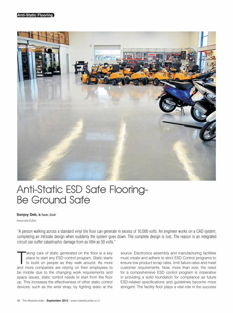
Anti-Static ESD Safe Flooring- Be Ground Safe
Taking care of static generated on the floor is a key place to start any ESD control program. Static starts to build on people as they walk around. As more
and more companies are relying on their employees to be mobile due to the changing work requirements and space issues, static control needs to start from the floor up. This increases the effectiveness of other static control devices, such as the wrist strap, by fighting static at the
source. Electronics assembly and manufacturing facilities must create and adhere to strict ESD Control programs to ensure low product scrap rates, limit failure rates and meet customer requirements. Now, more than ever, the need for a comprehensive ESD control program is imperative in providing a solid foundation for compliance as future ESD-related specifications and guidelines become more stringent. The facility floor plays a vital role in the success
Sonjoy Deb, B.Tech,’Civil’
Associate Editor
“A person walking across a standard vinyl tile floor can generate in excess of 10,000 volts. An engineer works on a CAD system, completing an intricate design when suddenly the system goes down. The complete design is lost. The reason is an integrated circuit can suffer catastrophic damage from as little as 50 volts.”
Anti-Static Flooring

www.masterbuilder.co.in • The Masterbuilder - September 2012 67
of any robust ESD control program. With its comprehensive product line, technical and contracting support, Protective Industrial Polymers is dedicated to providing fully compliant, turnkey ESD safe flooring solutions that provide peace of mind both today and in the future. ESD-safe flooring, in conjunction with ESD footwear has become a reality for today’s electronics industry. To meet this need, a variety of reportedly ESD-safe flooring materials have become commercially available which are intended to minimize the magnitude of charge generation.
ESD Basics
Electrostatic charge is typically generated when two dissimilar materials are brought into contact and then pulled apart, such as rubbing. When separated, one object will exhibit a net positive charge, the other a net negative charge. The exact magnitude of the charge is a function of the materials and of parameters such as surface texture, relative humidity, contact force, etc. The accumulation of charge causes a static potential to develop. A common example of frictional charging is the potential developed on a person walking across vinyl flooring or rolling a char across carpet. The magnitude of the voltage build-up is a function of flooring material, shoe sole material, relative humidity, weight of the person, the capacitance with respect to ground, etc. If the charged person then touches a sensitive electronic part, or if one grounds the part in the presence of a charged source, and Electrostatic Discharge (ESD) transient occurs that may damage or degrade the sensitive part.
Types of ESD Damage
ESD damage is of two types as mentioned below-
1. catastrophic failure resulting in the immediate destruction of an item
2. latent defect resulting in a reduced life expectancy of an item
Both types of damage can have serious financial impacts on businesses through increased quality-control failure rates for catastrophic events, and consumer product warranty claims for latent defects.
Ideal Dissipative Resistivity Range
Uncontrolled discharge of electrostatic potentials – ESD – is a major concern for manufacturers and assemblers of electronic products. Effective, reliable ESD control can generate significant cost savings and production efficiencies. Refer Figure 2 for the range.
Figure 1: Electrostatic Discharge generation through walking
Figure 2: The categories of electric conductivity of any object in terms of resistivity
Commonly used ESD safe Flooring materials
Anti-static grades of resin flooring are available in Types 3 to 8 (coatings, self-smoothing and trowel applied screeds). It is important for the specifier to understand that there is a wide range of products and properties available and to select the system that best meets the requirements for the working environment as a whole and to not treat the individual elements in isolation. Colour should be discussed with the flooring manufacturer, as there may be certain colour limitations on anti-static flooring due to the darkening effect of carbon. Some of the very commonly used ESD safe materials are as mentioned below.
A Conductive VinylB Dissipative VinylC Dissipative RubberD Conductive EpoxyE Dissipative. EpoxyF Dissipative QuartzG Dissipative UrethaneH Dissipative Acrylic
In addition to above various companies have come up with ESD safe tiles these days.
Experimental Apparatus and Procedures for testing ESD safe Flooring
Unfortunately, standardized test specifications and pro-
Anti-Static Flooring

68 The Masterbuilder - September 2012 • www.masterbuilder.co.in
cedures available for characterization of ESD flooring materials have not been a topic of concern until recent years. Of those specifications available, many are ill-defined or unrelated to ESD flooring, but adapted by the ESD industry while development of specific ESD flooring procedures are being formulated. Because of this, prototype test specifications were developed in cases where none currently exist, or modifications to traditionally accepted approaches of testing made when deemed appropriate. The critical aspect of this study was consistency. All floors were tested using identical test methodology, equipment & personnel. Test results should be considered on a com-parative basis. The following tests were performed or criteria reviewed during the course of the study:
Body Voltage Generation - There is no correlation between surface resistivity of a material and its ability to prevent charge generation. The abilities of a floor to inhibit charge generation and dissipate any accumulated charge are two properties that should always be considered during testing & evaluation. Charge generation caused by rubbing the sole of a shoe on various flooring had to be determined using a variety of shoes and personnel. Refer Figure 3 fir body voltage test configuration.
Figure 3: Body voltage test configuration
Surface Resistivity – As per ASTM D257, EOS/ESD-DS7.1 and NFPA 99, the point-to-point surface resistivity was checked using 5 pound conductive rubber electrodes connected to a voltmeter, spaced 3 feet apart using a 100 volt source. Refer Figure 4.
Appearance – The initial appearance, as well as weekly checks were performed. Color change, loss of finish, lifting, scuffing (see “scuffing”) bubbling, and dirt retention was
Figure 4: Surface resistivity test configuration
checked and each test site rated on a 1 – 10 scale with 1 being best.
Odor – For obvious reasons, the product was expected to have no offensive odor, as per ASTM D4078.
Resistance to Ground – Each of the floors were grounded and verified using a 100 volt source voltmeter and a five pound conductive rubber electrode, per NFPA 99 and EOS/ESD DS7.1. Refer Figure 5. The necessity of this particular test would depend upon the application. ESD flooring installed in an office area would not typically require grounding. However, in many manufacturing and assembly applications, the use of proper grounding would be essential if the operator were relying on the footwear and flooring as a source to ground.
Figure 5: Resistance to Ground Test Configuration
Static Decay – Static Decay tests were performed according to Fed Test Standard 101C, Method 4046, both with and without the addition of the human body. Current Federal test standards do not specify the introduction of a human body during testing. However, in order to properly
Anti-Static Flooring


70 The Masterbuilder - September 2012 • www.masterbuilder.co.in
analyze the floor’s ability to dissipate a charge on a human being, the introduction of an operator with and without ESD footwear was included in this study. Refer Figure 6.
Figure 6: Static decay test configuration
Scuff Resistance – Black marking resistance, as described in ASTM D 3714, is the ability of a floor to resist black marks usually caused by the impact of heels and soles of footwear, along with various type of wheels rolled across the surface.
Wear - AT&T, like most other companies, strives for flooring that requires very little maintenance or replacement. With the cost of flooring being particularly high, the necessity for replacement or recoating (in the case of “poured” and “rolled-on” flooring) was considered.
Required Maintenance - Most manufacturers of ESD flooring report very little required maintenance, such as an occasional sweeping and wet buffing with a water-and-cleaning mixture to get out ground-in dirt.
Slip-Resistance – For safety reasons, all floors must be UL certifiably slip resistant. This was accomplished using a portable Broom Grapper Machine, in lieu of laboratory testing, which entails the use of a James Machine or equivalent.
Installation Requirements of ESD Safe Flooring
All of the floors installed need to be connected to ground (typically using copper foil or wire). In addition, the tile & rubber flooring required to be installed using conductive adhesive. It should be noted that subfloor material may affect test results and hence care have to be taken for selecting different subfloor, such as concrete or wood. The epoxies & urethanes require more time & training to install than the tile or rubber floors. In addition, one of the epoxies & urethanes required evacuation of people in the immediate area due to strong odors. From a cost perspective, the
conductive adhesive used during tile & rubber installations are considerably more expensive than standard adhesive. It must be applied, in most cases, such that the layer of adhesive is spread evenly & thick enough to allow for even resistance across the surface of the flooring material.
Anti-Static Floor Finish Composition
The application and maintenance procedures and equipment for applying anti-static floor finish is basically the same as for standard floor finishes. Anti-static a/k/a electro-static discharge control (ESDC) floor finishes, however, have a different chemical structure that requires that special attention be paid to certain details when they are being applied and maintained. To provide static dissipation, anti-static finishes contain a special active ingredient. This active ingredient is not readily compatible with standard floor finish polymer chemistry. Producing a quality ESD finish requires that a finely tuned balance be achieved between having a sufficient concentration of the active ingredient to provide effective ESDC properties, while avoiding an unacceptable level of the side effects inherent when incorporating anti-static compounds into finishes. These side effects can include increased water sensitivity, reduced gloss, extended drying times and slipperiness. The cause of these side effects is the active ingredient’s tendency to absorb humidity present in the environment into the finish film. These hydrophilic properties help anti-static floor finishes to dissipate static charges. The consideration is that factors that inhibit regular floor finishes from drying and curing, like cool floor temperatures, high air temperatures coupled with high humidity and heavy coat application, also effect anti-static floor finishes, but to a much greater extent. This means that additional care and time must be taken when applying anti-static floor finishes.
Anti-Static Floor Finish Application Considerations
In order to achieve effective static dissipative properties, a sufficient amount of active ingredient must be present in the floor finish film. To obtain static dissipation on anti-static vinyl composition tile or antistatic epoxy floors, a minimum of two coats of StaticWorx Coat is necessary. On regular vinyl composition or other non anti-static flooring, a minimum of three coats is required. In order to function correctly, both immediately after application and over time, the anti-static active ingredient must effectively bond to the polymer chain. Once a floor finish is applied, film formation occurs in two phases.
1. The first phase involves the evaporation of the water from the finish. Most floor finishes, ESD safe and regular, contain between 75% and 84% water, which must leave the finish film before the second curing phase can start.
Anti-Static Flooring
www.masterbuilder.co.in • The Masterbuilder - September 2012 71
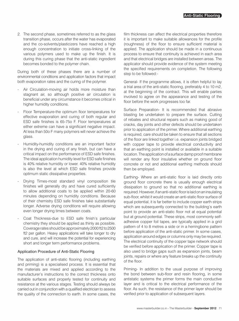
2. The second phase, sometimes referred to as the glass transition phase, occurs after the water has evaporated and the co-solvents/plasticizers have reached a high enough concentration to initiate cross-linking of the various polymers used to make up the finish. It is during this curing phase that the anti-static ingredient becomes bonded to the polymer chain.
During both of these phases there are a number of environmental conditions and application factors that impact both evaporation rates and the curing of the polymer.
- Air Circulation-moving air holds more moisture than stagnant air, so although positive air circulation is beneficial under any circumstance it becomes critical in higher humidity conditions.
- Floor Temperature-the optimum floor temperatures for effective evaporation and curing of both regular and ESD safe finishes is 65-75o F. Floor temperatures at either extreme can have a significant negative impact. At less than 50o F many polymers will never achieve the glass.
- Humidity-humidity conditions are an important factor in the drying and curing of any finish, but can have a critical impact on the performance of ESD safe finishes. The ideal application humidity level for ESD safe finishes is 40% relative humidity or lower. 40% relative humidity is also the level at which ESD safe finishes provide optimum static dissipative properties.
- Drying Times-most standard vinyl composition tile finishes will generally dry and have cured sufficiently to allow additional coats to be applied within 20-60 minutes depending on humidity conditions. Because of their chemistry ESD safe finishes take substantially longer. Adverse drying conditions will require allowing even longer drying times between coats.
- Coat Thickness-due to ESD safe finish’s particular chemistry they should be applied as thinly as possible. Coverage rates should be approximately 2000 ft2 to 2500 ft2 per gallon. Heavy applications will take longer to dry and cure, and will increase the potential for experiencing short and longer term performance problems.
Application Procedure of Anti-Static Flooring
The application of anti-static flooring (including earthing and priming) is a specialised process. It is essential that the materials are mixed and applied according to the manufacturer’s instructions to the correct thickness onto suitable surfaces and properly tested for continuity and resistance at the various stages. Testing should always be carried out in conjunction with a qualified electrician to assess the quality of the connection to earth. In some cases, the
film thickness can affect the electrical properties therefore it is important to make suitable allowances for the profile (roughness) of the floor to ensure sufficient material is applied. The application should be made in a continuous process to ensure that continuity is achieved in each area and that electrical bridges are installed between areas. The applicator should provide evidence of the system meeting the specified requirements on completion. The following step to be followed:-
General- If the programme allows, it is often helpful to lay a trial area of the anti-static flooring, preferably 4 to 10 m2, at the beginning of the contract. This will enable parties involved to agree on the appearance and testing of the floor before the work progresses too far.
Surface Preparation- It is recommended that abrasive blasting be undertaken to prepare the surface. Cutting of rebates and structural repairs such as making good of cracks, day joints and other defects should be undertaken prior to application of the primer. Where additional earthing is required, care should be taken to ensure that all sections of the floor are linked together i.e. expansion joints bridged with copper tape to provide electrical conductivity and that an earthing point is installed or available in a suitable location. The application of a surface damp proof membrane will render any floor insulative whether on ground floor concrete or not and additional earthing methods should then be employed.
Earthing- Where an anti-static floor is laid directly onto ground floor concrete there is usually enough electrical dissipation to ground so that no additional earthing is required. However, if an anti-static floor is laid on an insulating sub-floor, whilst it would create an anti-static floor surface of equal potential, it is far better to include copper earth strips which are subsequently connected to the building’s earth point to provide an anti-static floor not at equal potential but at ground potential. These strips, most commonly self-adhesive copper foil tapes, are typically applied in a grid pattern of 4 to 8 metres a side or in a herringbone pattern before application of the anti-static primer. In some cases, application around edges or columns only may be required. The electrical continuity of the copper tape network should be verified before application of the primer. Copper tape is also used to bridge gaps such as expansion joints, beam joints, repairs or where any feature breaks up the continuity of the floor.
Priming- In addition to the usual purpose of improving the bond between sub-floor and resin flooring, in some antistatic systems the primer forms the main conductive layer and is critical to the electrical performance of the floor. As such, the resistance of the primer layer should be verified prior to application of subsequent layers.
Anti-Static Flooring

72 The Masterbuilder - September 2012 • www.masterbuilder.co.in
Conclusion
Any industry where dust can present a problem or where stray electric currents are undesirable will have requirements for anti-static floors. The anti-static flooring has found tremendous application in the following industries (Refer some applications in Figure 7):-
- Electronic assembly,- Computers,- TV tubes,- Magnetic tape production,- Semi-conductor production of integrated circuits,- Micromechanics,- Gyroscopes, Miniature bearings,- CD or DVD players,- Optical lenses, Photographic film, Lasers,- Biotechnology,- Antibiotic production, Genetic engineering, Pharmaceutical
manufacture, Sterile disposables, Medical devices, Heart valves, Cardiac by-pass systems,
- Food & drink production,- Hospitals, Immunodeficiency therapy, Operating theatres- Clean rooms
Figure 7: Various Industrial Application of Anti-Static Flooring
Antistatic floors are more and more crucial to a production facility or storage facility today. Various available antistatic floor materials which can be installed on any sub base like asphalt, tiles, concrete, CBM etc. Different industries have varying requirements and standards vary from country to country. Many industries or organisations have their own internal standards for anti-static flooring. Requirements may relate to the antistatic or conductive nature of the flooring material to be used or to the anti-static characteristics of the finished floor. However specialized care needs to be taken as per the tests and standards mentioned here to any avoid mis-application.
Reference
- www.staticworx.com
- http://www.contec-aps.com/business-areas/industrial-flooring-roads-and-pavements/antistatic-flooring.html
- http://www.ecotileflooring.com/application-gallery.php?cat_id=2
- http://www.arts-ltd.co.uk/industrialfloorings/ucrete_antistatic_flooring.asp
- www.ferfa.org.uk
Anti-Static Flooring


74 The Masterbuilder - September 2012 • www.masterbuilder.co.in
Testing Interlayer Pull-off Adhesion in Concrete Floors by Means of Nondestructive Acoustic Method
In concrete floors there may occur all kinds of construction defects and damage. No adhesion at the topping/base interface is one of such defects. The degree of bonding
between the base and the topping depends on the proper preparation of the base surface. It is obvious that the durability of concrete floors greatly depends on this bond.
Pull-off adhesion fb, in practice determined by the seminondestructive pull-off method, is a measure of the interlayer bond. It should be noted that the effectiveness of the pull-off method depends on the number of cores drilled. According to [1], one core per 3 m2 of floor should be drilled. Such a high density of cores drilled has a significant adverse effect on the condition of the tested floor surface. After the tests the areas of the floor damaged by drilling have to be repaired, which is a major drawback of the pull-off method.
It has been demonstrated that the impulse response method is effective in locating noadhesion areas at the interlayer contact [2], but it is not known whether it is suitable for determining pull-off force fb. It could be applied for this purpose if the dependences between pull-off adhesion fb, determined by the seminondestructive pull-off method, and the values of the particular parameters registered using
the nondestructive impulse response method were reliably known. Then it would be possible to practically determine pull-off adhesion fb in any measuring point without harming the surface of the tested concrete floor. The present research was undertaken to determine the above dependencies.
Brief description of test methods
The nondestructive impulse response method consists in the generation of an elastic wave in the tested element by means of calibrated hammer tipped with rubber. The elastic wave frequency is in a range of 1-800 Hz. The tested element is hit with the hammer in selected measuring points. The signal of the elastic wave propagating in the element is registered by a geophone and simultaneously amplified by an amplifier. The registered signals are then processed using a dedicated software installed on a laptop (fig. 1a). Such parameters as: average mobility Nav , stiffness Kd, mobility slope Mp/N, mobility times mobility slope Nav•Mp and voids index v are registered to locate no-adhesion areas in a concrete floor [2]. The impulse response method is described in detail in [3-5].
In the case of the seminondestructive pull-off method, interlayer adhesion is determined through the measurement
The durability of concrete floors is to a large extent depends on the pull-off adhesion of the topping to the base. When making or repairing concrete floors it is highly important to properly prepare the interlayer bonding surface. The measure of the interlayer bond is the pull-off adhesion value. The latter is determined by seminondestructive pull-off tests. In this research the nondestructive acoustic impulse response method and the seminondestructive pull-off method were employed to test the interlayer pull-off adhesion in concrete floor models. The surface of the base layer in the latter had been prepared in four ways. The aim of the investigations was to find out whether it is possible to determine reliable dependencies between the particular acoustic parameters obtained from impulse response tests and the pull-off adhesion obtained from seminondestructive pull-off tests for different ways of preparing the surface of the concrete base.
Jerzy Hola1, Lukasz Sadowski1
1Institute of Building Engineering, Wroclaw University of Technology
Concrete Flooring NDT

www.masterbuilder.co.in • The Masterbuilder - September 2012 75
Fig. 1. a) impulse response method test set, b) pull-off method test set.
of the pulling off force by means of an actuator with a digital or dial pressure gauge. In order to test a concrete floor one must drill cores 50 mm in diameter and pull them off the base. The pulling off force value, displayed or indicated by the pressure gauge, is used to calculate pull-off adhesion fb [1]. Figure 1b shows the equipment used for testing by this method.
Range of tests
Tests were carried out on two 2500 2500 mm concrete floor models consisting of a 25 mm thick topping on a 125 mm thick base. The topping was made of C20/25 grade cement mortar. The base was made of grade C30/37 concrete and aggregate with a maximum grading of 8 mm. Prior to testing the elements had been stored at a temperature of 20 C 5 C in a laboratory. The base was laid on a 100 layer of sand. Impulse response and pull-off tests were carried out after the topping had cured for 90 days.
The aim of the tests was to find out if reliable dependencies between the particular impulse response parameters and pull-off adhesion could be established.
Four ways (denoted with Roman numerals from I to IV) of preparing the surface of the base were adopted (fig. 2). After the topping of the concrete floor model had been appropriately marked, 1500 1500 mm test areas were demarcated and a grid of points spaced at every 100 mm was marked on each of them, leaving a minimum margin of 500 mm from the edge. In total, 128 measuring points were marked. The columns and the rows were denoted with respectively letters from A to H and numbers from 1 to 16.
The nondestructive impulse response tests consisted in exciting an elastic wave in each point of the measuring grid by means of the calibrated hammer (fig. 3a). As a result, the characteristic acoustic parameters Nav, Kd and Mp/N (defined in fig. 2) were determined in each of the points.
The pull-off tests consisted in determining the adhesion of the topping to the base through the measurement of the pulling off force by means of the actuator with a digital pressure gauge. For this purpose cores 50 mm in diameter were drilled in the topping in the same points in which
Fig. 2. Ways of preparing concrete base surface and nondestructive method and seminondestructive method with parameters used.
Fig. 3. a) testing by nondestructive impulse response method, b) cores drilled in topping.
previously the impulse response tests had been carried out, and pulled off from the base (fig. 3 b).
Test results and their analysis
Selected statistical characteristics of the parameters determined by the nondestructive impulse response method and by the seminondestructive pull-off method are shown in table 1. The impulse response method yielded average mobility Nav ranging from 31.145 to 119.988 m/s•N for surface I, from 57.211 to 783.872 m/s•N for surface II, from 54.805 to 783.872 m/s•N for surface III and from 39.467 to 99.218 m/s•N for surface IV. The highest values of average mobility Nav were obtained for surface II and the lowest for surface I.
Stiffness Kd ranged from 0.004 to 0.119 for surface I, from 0.002 to 0.116 for surface II, from 0.003 to 0.115 for surface III and from 0.001 to 0.075 for surface IV. The highest values of stiffness Kd were obtained for surface I and the lowest for surface IV.
Concrete Flooring NDT

76 The Masterbuilder - September 2012 • www.masterbuilder.co.in
Mobility slope Mp/N ranged from 0.011 to 3.997 for surface I, from 0.0336 to 9.722 for surface II, from 0.603 to 12.777 for surface III and from 0.098 to 3.217 for surface IV. The highest values of mobility slope Mp/N were obtained for surface III and the lowest for surface IV.
The seminondestructive pull-off method yielded pull-off adhesion fb ranging from 0.662 to 1.299 MPa for surface I, from 0.306 to 0.688 MPa for surface II, from 0.204 to 0.891
Way of preparing surface of base
Parameter name I II III IV
Average mobility Nav
Average 69.049 361.573 245.078 72.807
Standard deviation 20.701 297.336 207.726 14.481
Minimum 31.145 57.211 54.805 39.467
Maximum 119.988 973.371 783.872 99.218
Stiffness Kd
Average 0.041 0.032 0.030 0.026
Standard deviation 0.034 0.030 0.033 0.020
Minimum 0.004 0.002 0.003 0.001
Maximum 0.119 0.116 0.115 0.075
Mobility slope Mp/N
Average 1.779 2.716 4.172 1.169
Standard deviation 1.174 2.230 3.545 0.696
Minimum 0.011 0.336 0.603 0.098
Maximum 3.997 9.722 12.777 3.217
Pull-off adhesion fb
Average 0.987 0.515 0.497 0.658
Standard deviation 0.118 0.086 0.137 0.204
Minimum 0.662 0.306 0.204 0.306
Maximum 1.299 0.688 0.891 1.274
Table 1. Selected statistical characteristics of parameters determined by nondestructive impulse response method and seminondestructive pull-off method.
MPa for surface III and from 0.306 to 1.274 MPa for surface IV. The highest average values of pull-off adhesion fb were obtained for surface I and the lowest for surface II.
The test results, in the form of dependencies between the values of parameters Nav, Kd and Mp/N and the value of pull-off adhesion fb, for the four ways of preparing the bonding surface are shown in figs 4-6. For each of the dependencies a regression line equation (derived by the
Concrete Flooring NDT


78 The Masterbuilder - September 2012 • www.masterbuilder.co.in
Fig. 4. Dependence between pull-off adhesion fb and average mobility Nav: a) surface I, b) surface II, c) surface III, d) surface IV.
least squares method) and determination coefficient r2 were determined.
Figure 4 shows the dependencies between pull-off adhesion fb and average mobility Nav.
It appears that regardless of base surface preparation
Fig. 5. Dependence between pull-off adhesion fb and stiffness Kd: a) surface I, b) surface II, c) surface III, d) surface IV.
method, the dependencies are similar, i.e. as average mobility Nav increases, pull-off adhesion fb decreases. Determination coefficient r2 assumes values from 0.7115 for surface I to 0.3417 for surface III.
Figure 5 shows the dependencies between pull-off adhesion fb and stiffness Kd. It appears that regardless of base surface preparation method, the dependencies are similar,
Concrete Flooring NDT

www.masterbuilder.co.in • The Masterbuilder - September 2012 79
i.e. as stiffness Kd increases so does pull-off adhesion fb. Determination coefficient r2 assumes values from 0.5600 for surface I to 0.4091 for surface II.
Figure 6 shows the dependencies between pull-off adhesion fb and mobility slope Mp/N. It
appears that regardless of base surface preparation method the dependencies are similar, i.e. as stiffness Kd increases, mobility slope Mp/N. decreases. Determination coefficient r2 assumes values from 0.6957 for surface I to 0.3719 for surface II.
Conclusions
The interlayer pull-off adhesion in two concrete floor models was determined by respectively the nondestructive acoustic impulse response method and the seminondestructive pulloff method. The aim of the tests was to find out if reliable dependencies between the particular parameters registered using the impulse response method and the pull-off adhesion determined by the pull-off method could be established.
The results of the tests show that regardless of the way of preparing the surface of the base the dependencies between pull-off adhesion fb determined by the seminondestructive pull-off method and the particular acoustic parameters determined by the nondestructive impulse response method are similar and can be described by rectilinear mathematical functions.
However, the values of determination coefficient r2, calculated for the determined dependencies are not too high and depend on the base surface preparation method. For example, the highest value (0.7115) of this coefficient was obtained for a ground surface covered with a bonding layer and parameter Nav and the lowest value (0.3417) was obtained for the raw postconcreting surface and parameter Nav.
Considering that the values of determination coefficient r2 yielded by the impulse response tests are not too high, it seems that several parameters, including the ones describing the topography of the base surface, should be taken into account simultaneously in order to increase the reliability of the nondestructive evaluation of the interlayer
Fig. 6. Dependence between pull-off adhesion fb and mobility slope Mp/N: a) surface I, b) surface II, c) surface III, d) surface IV.
Concrete Flooring NDT
80 The Masterbuilder - September 2012 • www.masterbuilder.co.in
pull-off adhesion in concrete floors. The parameters can be nondestructively determined before the topping is laid. Research towards this aim is underway and artificial neural networks are to be used in order to interrelate a larger number of parameters.
Acknowledgements
The above research was carried out as part of research project no. 0926/B/T02/2011/40 “New Nondestructive Way of Evaluating Interlayer Pull-off Adhesion in Concrete Floors by Means of Artificial Neural Networks” funded by the National Centre of Science in Cracow.
References
1. EN 12504-3:2006,Testing concrete in structures, Part 3:
Nondestructive tests, Determination of pull-off force (in Polish).
2. J Hola, L Sadowski and K Schabowicz, “Nondestructive identification of delaminations in concrete floor toppings with acoustic methods”, Automation in Construction, vol. 21, no. 7, 2011.
3. A Davis, “The non-destructive impulse response test in North America: 1985–2001”, NDT&E International, Vol. 36, p. 185-193, 2003.
4. N Ottosen, M Ristinmmaa and A Davis, “Theoretical interpretation of impulse response tests of embedded concrete structures”, Journal of Engineering Mechanics, Vol. 130, p. 1062-1071, 2004.
5. A Davis, B Hertlein, K Lim and K Michols, “Impulse response and impact-echo stress wave methods: advantages and limitations for the evaluation of highway pavement concrete overlays”, Conference on Nondestructive Evaluation of Bridges and Highways, Scottsdale, 88, 1996.
Concrete Flooring NDT


94 The Masterbuilder - September 2012 • www.masterbuilder.co.in
Industrial Flooring Installation Challenges
Heavy duty flooring systems and coatings can produce an aesthetically pleasing, chemical, wear resistant barrier that protects the concrete
substrates. Concrete floors can be expensive to replace or maintain if proper care is not taken to protect them.
Even though concrete can be a very strong, hard substrate, unprotected concrete is subject to deterioration. Concrete is very porous and can be subjected to chemical attack and physical abuse. Coatings and surfacings are used to protect concrete, improve appearance and provide ease of maintenance.
Seamless floors are manufactured “in place”. The chemical reaction of the polymeric materials must be controlled for successful installation. Failures and challenges can occur prior to, during or after the installation. Many of these problems can be prevented. When applying coatings and heavy duty flooring systems, it is important that the contractor strictly adhere to the application requirements for each product. Deviations from the manufacturer’s instructions and job site specifications may result in less than anticipated results. Avoiding these issues and preventing problems is the basis of an expert flooring contractor.
Substrate Evaluation
The first critical step in avoiding flooring problems is the evaluation of the substrate. Concrete, the primary substrate on which seamless flooring systems are applied, is porous. It breathes and absorbs liquids when exposed to the environment. This can present a problem both during and after the installation of a non-permeable fluid applied flooring system.
During the substrate evaluation process, responsible
parties must determine whether an effective vapor barrier exists below the slab, what potential contaminants are in the concrete and the overall soundness of the concrete, including joint and crack movement.
The effects of moisture vapor emissions from the slab must be thoroughly evaluated. Remove contaminants from the substrate prior to the installation. Mechanical surface preparation may remove some of the surface contamination, but chemicals and oils that penetrate the concrete substrate also must be removed or neutralized. Weak concrete must be replaced and spalls must be repaired with an appropriate mortar or compatible material to speed the repair and recoat times.
The foundation of any coating system is surface preparation. The purpose of surface preparation is to remove all contaminants such as concrete laitance, existing coatings, hardeners, sealers and curing compounds that can interfere with adhesion. Surface preparation also develops a surface profile to promote mechanical adhesion. Although there are many methods of surface preparation available, shot blasting is normally the preferred method.
System Recommendation
No two flooring projects are ever the same and never as simple as they may first appear. Many contractors are asked to make product and system recommendations. Representatives from the manufacture may assist in making these recommendations.
Many factors need to be considered when making any recommendations:
- Shut-down time- VOC’s and odor tolerance
Specifier’s and contractors not only need to properly evaluate the substrate, make proper system recommendations and pay attention to details during the installation, but they must also have an understanding of potential problems and their causes to aid in the successful installation of heavy duty floor coatings and systems. Understanding these issues minimizes problems and facilitates a successful installation.
James C. ZieglerArmorSeal, Cincinnati, Ohio
Flooring Installation

www.masterbuilder.co.in • The Masterbuilder - September 2012 95
- Chemical resistance- Wear and impact resistance- Longevity of the system- Thermal resistance- Slip resistance- Cleanabilty- Light reflectivity- Installation conditions such as temperature, humidity
etc.
Problem Recognition, Causes, Prevention and Remediation Contractors come across challenges everyday when applying industrial coatings and industrial flooring systems. Recognizing problems, causes, prevention and remediation is crucial for successful application.
Bubbles: Bubbles may appear as small as a pinhead or greater. They may appear throughout the entire coating or in clusters. (Figure 1)
not apply coating. Wait to apply materials when the air temperature is falling. Double priming may also be helpful or using a water-based epoxy primer to seal off entrapped air in the concrete.
Remediation: Thoroughly abrade affected coating with Figure 1, Bubbles
Remediation: Thoroughly abrade bubbled coating with sandpaper or a floor grinder, thoroughly vacuum area and solvent wipe with a strong, clean solvent recommended by the coatings manufacturer. Re-prime and recoat.
Outgassing: Air pockets in porous concrete escaping during the curing process, trapped in the film, creating bubbles. These bubbles typically have a pinhole that penetrates directly to the substrate. (Figure 2).
Cause: When the air temperature above the substrate is warmer than the substrate temperature and the humidity is lower, the air trapped in the pores of the concrete expands and the air moves out of the concrete creating bubbles.
Prevention: Check temperature and humidity conditions of the air and substrate. If the temperature is rising, do Figure 2, Outgassing
Cause Prevention Remediation
-Air entrainment in the resins during mixing and or application
-Use manufacture’srecommended equipment for mixing and application.When using 100% solids material, spread with a squeegee, back roll with a high quality, lint-free, medium nap roller and use a spike or spiney roller toimprove air release.
Thoroughly abrade bubbled coating with sandpaper or a floor grinder, thoroughlyvacuum area and solvent wipe with a strong, clean solvent recommended bymanufacturer. Reprime and recoat.
-Excessive heat
- Try to avoid elevatedtemperatures. Monitor the environmental conditions, air, substrate temperaturesand humidity. Condition materials for several hours prior to application.
-Direct sunlight
- Cover windows anddoorways to prevent direct sunlight exposure to thecoatings prior to, during and through the cure period.
Bubbles: Air bubbles may appear as small as a pinhead or greater. They may appear throughout the entire coating or in clusters.
Flooring Installation

96 The Masterbuilder - September 2012 • www.masterbuilder.co.in
sandpaper or a floor grinder and thoroughly vacuum area and solvent wipe with a strong, clean solvent recommended by manufacturer. Reprime using a high build, fast cure primer. Large craters may be patched with a quick set crack filler.
Poor Intercoat Adhesion: Poor intercoat adhesion occurs when one coating does not adhere to the previous cured coat. (Figure 3) Prevention: Check the manufacturer’s product data
sheet for recoat window times. Do not exceed the recoat window. If the recoat window has been exceeded, consult manufacture’s recommended recoat procedure.
Cause: When coatings are installed at temperatures less than 5oF above dew point, moisture may condense on the surface acting as a bond-breaker and could cause inter-coat adhesion problems.
Prevention: Check temperature and humidity of substrate and air to ensure the substrate temperatures are at least 5oF above the dew point.
Remediation: Mechanically remove any poorly bonded coating. This may be achieved by shot blasting, grinding or sanding. Existing coating must have a dull surface from the mechanical preparation. Vacuum and solvent wipe existing coating to remove any dust, debris or other contaminants. Reprime and recoat according to the manufacturer’s instructions.
Bond Failure at Substrate
Bond failure at the substrate occurs when the coating or flooring system delaminates at the bond line. (Figure 4).
Cause1: Inadequate surface preparation, preventing a good mechanical bond or leaving a surface contaminant, which acts as a bond breaker.
Prevention: The foundation of any coating or flooring
Cause Prevention Remediation
- When the air above the substrate is warmer than the substrate temperature and the humidity is lower, the air trapped in the pores of the concrete expands and the air moves out of the concrete creating bubbles.
-Check temperature and humidity conditions of theair and substrate. If thetemperature is rising do not apply coating. Wait to apply materials when temperature is falling. Double priming may also be helpful or use a water-basedepoxy primer to seal offtrapped air in the concrete.
Thoroughly abrade bubbled coating with sandpaper or a floor grinder, thoroughlyvacuum area and solvent wipe with a strong, clean solvent recommended bymanufacturer. Reprimeusing a high build, fast cure primer. Large craters may be patched with quick set crack filler.
Outgassing: Air pockets in porous concrete escaping during the curing process, trapped in the coating crating bubbles.
Figure 3, Poor Intercoat Adhesion
Cause 1: Improper preparation of the previous coating.
Prevention: Prior to applying multiple coats of material, the previous coating must be properly prepared and free from contaminants. These contaminants include dust, dirt, water or amine blush, and all contaminants must be removed prior to coating.
Cause 2: Recoating outside of recoat window. Most coatings have a range of time or recoat window when a subsequent coat can be applied without additional preparation.
Cause Prevention Remediation
-Improperly preparedprevious coating
-Prior to applying multiple coats of material, the previous coating must be properly prepared and free from contaminants. These contaminants include dust, dirt, water or amine blush,which must be removed prior to coating.
Mechanically remove any poorly bonded coating. This may be achieved by shot blasting, grinding orsanding. Existing coating must have a dull surface from the mechanical preparation. Vacuum and solvent wipe existing coating to remove any dust,debris or othercontaminants. Reprime and recoat according tomanufacture’s instructions
-Recoating outside of recoat window. Most coatings have a range of time when asubsequent coat can be applied without additional preparation.
-Check manufacture’sproduct data sheet for recoat window times. Do not exceed recoat window. If the recoat window has beenexceeded, consultmanufacture’srecommended recoatprocedure.
Poor Intercoat Adhesion: Poor intercoat adhesion is when one coating application does not adhere to the previous cured coating.
Flooring Installation


98 The Masterbuilder - September 2012 • www.masterbuilder.co.in
system is the surface preparation. The purpose of surface preparation is to remove all contaminants such as concrete laitance, existing coatings, hardeners, sealers and curing compounds that can interfere with adhesion and develop a surface profile to promote mechanical adhesion. Disbonding from the substrate at the termination or at transitions is related to the installation detail. Traffic edges require a keyed termination.
Figure 4, Bond Failure at Substrate
Figure 5, Poor Hardness or Tackiness
Remediation: Mechanically remove coating or flooring system. The substrate must then be prepared by following manufacturer’s recommend surface preparation guidelines.
Poor Hardness or Tackiness
After sufficient time, material has not developed proper hardness or may appear tacky on the surface. (Figure 5)
Cause: Applying coatings when temperatures are below recommended minimum range. When temperatures are below the manufacturer’s recommendation, materials may never completely cure.
Prevention: Strictly adhere to manufacturer’s recommended installation temperature guidelines. Monitor environmental
conditions and select the correct products for the application.
Cause: Improper mixing or measuring ratio.
Prevention: Use proper equipment, accurately measure components and mixing procedures in accordance with the manufacturer’s installation instructions. Mixing time, equipment, and procedures are very crucial and should not be deviated. Do not mix partial units if using small kits or different chemistries.
Remediation: Remove any soft spots, contamination or dirt from the surface. This may have to be scraped away using a floor scraper or hand tools. Once excess material has been removed, solvent wipe to remove any residue. Once removed, mechanically prepare surface and recoat.
Amine Blush or Greasy Film on the Surface.
Amine blush is a normal chemical reaction between amine-curing agents and carbon dioxide when in the presence of moisture forming a carbonate, which appears as a greasy film on the surface. This is especially true at low temperatures and high humidity. (Figure 6)
Cause: Amines react with carbon dioxide and moisture to create a greasy, oily film on the surface.
Cause Prevention Remediation
-Inadequate surfacepreparation preventing a good mechanical bond or leaving a surface contaminant, which acts as a bond breaker.
- Remove all contaminantssuch as the concretelaitance, existing coatings hardeners, sealers and curing compounds that caninterfere with adhesion and develop a surface profile to promote mechanical adhesion.
Mechanically removecoating or flooring system. Then the substrate must beprepared by followingmanufacturer’s recommend surface preparation guidelines.
Bond Failure at Substrate: Bond failure at the substrate occurs when the coating or flooring system delaminates at the bond line.
Cause Prevention Remediation
-Applying coatings when temperatures are below recommended minimum range. When temperatures are below manufacture’srecommendation, materials may never reach complete cure.
-Use proper equipment; accurately measure components and mixing procedures in accordance with manufacture’s installation instructions.
Remove any soft spots,contamination or dirt from the surface. After excess material has been removed, solvent wipe to remove anyresidue. Once emoved,mechanically preparesurface and recoat.
Poor Hardness or Tackiness: After sufficient time, material has not developed proper hardness or be tacky on the surface.
Flooring Installation

www.masterbuilder.co.in • The Masterbuilder - September 2012 99
Prevention: Check environmental conditions and apply materials when the temperature is a minimum 5oF above dew point and rising. Do not use propane heat in closed environments because they emit CO2.
Remediation: The amine blush or greasy film must be removed. Solvent wiping prior to the application of the next coat is also utilized, but it can leave residual contaminants if not thoroughly cleaned. It is best removed by using a hot water detergent scrub and rinse.
Fish-eyes
Fish-eyes are areas where the coating pulls away from the surface or previous coating. (Figure 7).
Cause: Contamination on the substrate or coated surface are frequently caused by blush, surface oils, animal fats, vegetable oil, grease, silicone or petroleum based products.
Prevention: Prior to application of any coating, the substrate must be inspected for any contaminants including dirt, debris, amine blush or residues.
Remediation: The surface must be thoroughly sanded
or abraded to remove the contamination and to roughen the previous coat. Once the surface is mechanically prepared, solvent wipe to remove any dust, dirt or residual contamination, prior to recoating.
Disbonding in Form of a Blister
Moisture vapor transmission will cause loss of adhesion and blistering. The moisture in the pores of concrete will migrate toward the warm, dry air above the substrate. (Figure 8).
Cause Prevention Remediation
Amines react with carbon dioxide and moisture to create a greasy, oily film onthe surface.
-Check environmentalconditions and applymaterials when thetemperature is a minimum 5°F about dew point. Do not use propane heat in closed environments.
Remove any soft spots,contamination or dirt from the surface. After excess material has been removed, solvent wipe to remove anyresidue. Once emoved,mechanically preparesurface and recoat.
Cause Prevention Remediation
-Contamination on thesubstrate or coated surface are frequently caused by blush, surface oils, animalfats, vegetable oil, grease, silicone and petroleum based products.
-Prior to apply any coating the substrate must be inspected for any contaminants including dirt, debris, amine blush or residues.
The surface must bethoroughly sanded orabraded to remove thecontamination and toroughen the previous coat. Once the surface is mechanically prepared, a solvent wipe to remove anydust, dirt or residualcontamination must be done prior to recoating.
Figure 7, Fish-Eyes
Amine Blush: Amine blush is a normal chemical reaction between amine-curing agents and carbon dioxide when in the presence of moisture form a carbonate, which appears as a greasy film on the surface.
Figure 6, Amine Blush
Fish Eyes: Fish-eyes are areas where the coating pulls away from the surface or previous coating.
Figure 8, Disbonding from Moisture Vapor Transmission
Flooring Installation


104 The Masterbuilder - September 2012 • www.masterbuilder.co.in
Figure 9. Color shading
Cause Prevention Remediation
-Moisture vaportransmission
-After surface preparation, the substrate must be tested for moisture vapor transmission with a calcium chloride test kits at “use”conditions. The resultsmust generally be less than 3 pounds of moisture per 1000 square feet per 24hours period. The coatings or flooring systems must also be installed at “use”conditions.
The flooring system must be removed. Raising the temperature and increasing the ventilation prior toretesting may help remove the excess moisture. Treating the surface with apenetrating silicate,siloxanes, or gel forming polymers may decrease thepermeability and inhibit the path of moisture.
Cause Prevention Remediation
-Using multiple lotnumbers.
-Check batches whilestaging the project. If there are multiple batch numbers, “boxing” batches together for uniform color.
Thoroughly abrade coating with sandpaper or a floor grinder, thoroughly vacuumarea and solvent wipe with a strong, clean solvent. Reprime and recoat.
-Improper mixing. - Always use proper mixing equipment when mixing industrial coatings and floorsurfacing products. Use a variable speed drill, Jiffy mixing blade, on low speed.Premix material prior toadding multiple components together. Once premixed,slowly pour omponentstogether and mix for 2 to 3 minutes and until uniform. Carefully follow manufacture’s instructions.
Disbonding in form of a blister: Moisture vapor transmission will cause loss ofadhesion and blistering. The moisture in the pours of concrete will migrate toward the warm, dry air above the substrate.
Cause: Moisture vapor transmission.
Prevention: After surface preparation, the substrate must be tested for moisture vapor transmission with a calcium chloride test kit at “use” conditions. The results must generally be less than 3 pounds of moisture per 1000 square feet per 24 hours period. The coatings or flooring systems must also be installed at “use” conditions.
Remediation: The flooring system must be removed. Raising the temperature and increasing the ventilation prior to retesting may help remove the excess moisture. Treating the surface with a penetrating silicate, siloxanes, or gel forming polymers may decrease the permeability and inhibit the path of moisture.
Color Shading
Uniform color but different shades of color, sometimes dark or light streaks appear in the film. (Figure 9).
Cause: Using multiple batch numbers.
Prevention: Check batches while staging the project. If there are multiple batch numbers, “boxing” batches together for uniformly of color.
Cause: Improper mixing.
Prevention: Always use proper mixing equipment when mixing industrial coatings and floor surfacing products. Use a variable speed drill, Jiffy mixing blade, on low speed. Premix material prior to adding multiple components together. Once premixed, slowly pour components together and mix for 2 to 3 minutes and until uniform. Carefully follow manufacturer’s instructions.
Remediation: Thoroughly abrade coating with sandpaper or a floor grinder. Thoroughly vacuum area and solvent wipe with a strong, clean solvent. Reprime and recoat.
Summary
Heavy duty flooring systems and industrial coatings require surface evaluation, accurate system selection and professional installation to prevent expensive problems. Taking the time and effort to understand the potential problems and implementing the correct measures to prevent them is the hallmark of a successful professional flooring installer.
Bubbles: Air bubbles may appear as small as a pinhead or greater. They may appear throughout the entire coating or in clusters.
Color shading: Difference in shades of color.
Flooring Installation


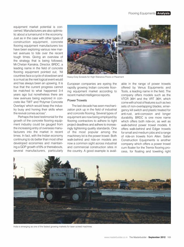


176 The Masterbuilder - September 2012 • www.masterbuilder.co.in
Effect of Silica Fume on Concrete at Different Curing Conditions
Concrete is a composite construction material composed of cement and other cementitious materials such as silica fume, fly ash and slag cement, aggregate
(generally a coarse aggregate made of gravels or crushed rocks such as limestone, or granite, plus a fine aggregate such as sand), water, and chemical admixtures. Silica fume (SF) is a byproduct of the silicon and ferrosilicon industry. Silica fume is a very reactive pozzolonic material because of its extreme fineness and very high amorphous silicon dioxide content. Mechanism of silica fume in concrete can be described basically under three roles: (i) pore-size refinement and matrix densification,(ii) reaction with free-lime, and (iii) cement paste–aggregate interfacial refinement. The mechanical properties and durability are improved because of the enhancement in interfacial or bond strength [1]. Mechanism behind is not only connected to chemical formation of C–S–H (i.e. pozzolonic reaction) at interface, but also to the microstructure modification (i.e. CH) orientation, porosity and transition zone thickness) as well.
Experimental work
General
Experimental work includes the determination of preliminary properties of ingredients of concrete, mix design process for determination of quantities of ingredients, tests for com-pressive strength and ultrasonic pulse velocity (USPV).
Materials
Different tests carried out on the materials in the experimental work are presented below.
Cement
Cement used in the investigation is Ordinary Portland Cement (OPC) of grade 53
- OPC confirming to Indian standards IS: 8112-1989 [2].
Coarse aggregates
The coarse aggregates of size 20mm MSA (maximum size
Bisetti Sameer Charan1, Dr. Bulu Pradhan2
1B.Tech Civil 4th Year, SRM University, Ramapuram 2Department of Civil Engineering, Indian Institute of Technology Guwahati
Several types of industrial byproducts are generated. With increased environmental awareness and its potential hazardous effects, utilization of industrial byproducts has become an attractive alternative to disposal. One such by-product is silica fume (SF), which is a byproduct of the smelting process in the silicon and ferrosilicon industry. Silica fume is very effective in the design and development of high strength high performance concrete. This paper presents the results of an experimental investigation on the effect of different amounts of silica fume (SF) and water to binder ratios (w/b) on the residual compressive strength and ultrasonic pulse velocity (USPV) of concrete after exposure to different curing conditions i.e. hot water curing (Temperature at 700C) and normal moist water curing at 7 days and 14 days. Several mixes were prepared based on dosage of silica fume at 0%, 5%, 7.5% and 10% by mass at different w/b ratios of 0.45, 0.50, and 0.55. 5%, 7.5%, 10% SF by mass are named as mixes M1, M2, and M3 at w/b ratio 0.45 cured at 14days. 10% SF by mass are mixes M4 and M5 at w/b ratio 0.50, 0.55 respectively at 7days curing and 0%SF (100% OPC) by mass are mixes M6 and M7 at w/b ratio 0.50, 0.55 respectively at 7days curing.It is observed that M1 at normal water (NW) curing has showed highest compressive strength and M1 at hot water (HW) curing has showed least compressive strength at 14days. And M6HW has showed highest compressive strength and M7NW has showed least compressive strength at 7days.It is observed that M1NW curing has showed highest ultrasonic pulse velocity and M3HW curing has showed least ultrasonic pulse velocity at 14days. And M6HW has showed highest ultrasonic pulse velocity and M7HW has showed least ultrasonic pulse velocity at 7days.
Research Study Silica Fume

www.masterbuilder.co.in • The Masterbuilder - September 2012 177
SF- Silica Fume
Table 2.1 Mix proportions of concrete mixes for different w/b ratios
of aggregate) and 12.5mm MSA are used in the proportion of 66% and 34% respectively by mass after many trial tests.
Fine aggregates
River sand was used as fine aggregates in the present study. The sieve analysis of sand was carried out as per the guidelines given in IS 383-1970. From the cumulative % passing values, it is observed that, the sand is confirming to grading zone-III at higher sieve size and zone-II at smaller sieve size as per IS 383-1970.
Super plasticizer
The super plasticizer used in the present study was Glenium 51 based on modified polycarboxylic ether (PCE) polymers. It gives the highest durability and performance for the concrete. In the present study 1% super plasticizer by mass of binder is used.
Mix proportioning of concrete
The mix proportioning of ingredients of concrete is done by using DOE (British method) with some modifications [3]. For the present investigation three different w/b ratios namely 0.45, 0.5, 0.55 have been selected. The mix proportioning method includes calculation of water content for the slump value (30-60 mm) followed by calculation of binder content and the wet density of the concrete corresponding to the specific gravity of combined aggregates. After that the fine aggregate (sand) and coarse aggregate contents are calculated.
Mix proportions of concrete mixes
The mix proportions for different concrete mixes are presented in Table 2.1. The water content used was 190 kg/m3 in all the mixes.
Preparation of specimens for Compressive strength test and Ultrasonic pulse velocity
The cubes of size 150mm x 150mm x 150mm were prepared
Mix type Binder Type w/b ratio Binder content (kg/m3)Mix proportion (by mass)
(Water: cement: sand: coarse aggregates)
M1 OPC + 5%SF
0.45 423 0.45 : 1 : 1.44 : 2.79M2 OPC + 7.5%SF
M3 OPC + 10%SF
M4 OPC + 10%SF 0.50 380 0.50 : 1 : 1.98 : 3.84
M5 OPC + 10%SF 0.55 345.45 0.55 : 1 : 1.83 : 3.56
M6 OPC 0.50 380 0.50 : 1 : 1.98 : 3.84
M7 OPC 0.55 345.45 0.55 : 1 : 1.83 : 3.56
from ordinary Portland cement, 20mm and 10mm aggregates and different dosage of silica fume at 5%, 7.5% and 10% by mass of total binder and super plasticizer at 1% by mass of total binder at varying w/b ratios of 0.45, 0.50 and 0.55. After 24 hours of preparation, the cubes were demoulded and then subjected to hot water curing (Temperature at 700C) and normal water curing for concrete mixes M1, M2, M3 for 14days and concrete mixes M4, M5, M6, and M7 for 7days. After completion of curing, the cubes were tested for ultrasonic pulse velocity (USPV) and compressive strength.
Ultrasonic Pulse Velocity Method
This test is done to access the quality of concrete by ultrasonic pulse velocity method as per IS- 13311 (part 1) – 1992 [4]. The underlying principle consists of measuring the time of travel of an ultrasonic pulse passing through the concrete being tested. The ultrasonic pulse velocity values were measured after placing the transmitting and receiving transducers on the two opposite faces of the cubes. Com-paratively higher velocity is obtained when concrete quality is good in terms of density, uniformity, homogeneity etc.
Compressive strength test
The compressive strength of cubes was determined in the compression testing machine. For each mix six cubes were tested in which three replicate cubes for hot water curing
Fig. 2.4 Ultrasonic Pulse Velocity Test Fig. 2.5 Compressive Strength test
Research Study Silica Fume

178 The Masterbuilder - September 2012 • www.masterbuilder.co.in
and three replicate cubes for normal water curing and the average values in MPa were reported.
Results and Discussion
Ultrasonic pulse velocity (USPV)
The USPV test was conducted on the cube specimens at the age of 14 days for mixtures M1 to M3 and 7 days for mixtures M4 to M7. The USPV values for the various mixes are presented in Table 3.1 for 14days cubes and Table 3.2 for 7days cubes. The plots of ultrasonic pulse velocity for different mixes are shown in Fig.3.1 and Fig 3.2 for 14days & 7days of curing respectively. From the results it was observed that the cubes which were cured in normal water exhibited more USPV values than the cubes cured in hot water (Temperature 700C). The mix M1NW (5% MS with w/b-0.45 at 14days normal moist water curing) has exhibited higher value of USPV whereas mix M7HW (OPC with w/b-0.55 at 7days hot water curing) has shown lower value of USPV.
Compressive strength
When silica fume is added to concrete, it results in higher compressive strength of the mix. This is mainly due to the production of additional C-S-H gel in pozzolonic reaction that results in denser microstructure of concrete. As already mentioned, the compressive strength was determined for concrete mixes M1 to M3at the age of 14 days and at the age of 7 days for mixtures M4 to M7. The compressive strength values for the various mixes are presented in Table 3.3 for 14days curing and Table 3.4 for 7days curing.
From the Fig.3.3 it is observed that the 14day compressive strength values of normal water cured concrete mixes with 5% SF & 7.5% SF were higher than that of the concrete mix cured with hot water. However the 14day compressive strength value of hot water cured concrete mix with 10% SF was higher than that of the concrete mix cured with normal water.
From the Fig.3.4 it was observed that the 7day compressive strength values of all the hot water cured concrete mixes were higher than that of all the concrete mixes cured with normal water. And 7day compressive strength value of hot water cured concrete mix with 100% OPC was higher than that of the concrete mixes with silica fume. This is because
Mix Type Ultrasonic Pulse Velocity (m/sec)
Hot Water Curing Normal Water Curing
M1 4210 4670
M2 3920 4650
M3 4030 4090
Table 3.1 USPV values of concrete mixes for 14days curing
Fig.3.1 USPV values of concrete mixes under hot water (Temperature at 700C) curing and normal water curing for 14days
Mix Type Ultrasonic Pulse Velocity (m/sec)
Hot Water Curing Normal Water Curing
M4 4100 4390
M5 4080 4130
M6 4570 4420
M7 3860 3990
Table 3.2 USPV values of concrete mixes for 7days curing
Fig.3.2 USPV values of concrete mixes under hot water (Temperature at 700C) curing and normal water curing for 7days
of the reason that the pozzolonic reaction of silica fume achieves in the later stage when compared to Portland cement.
Conclusions
In the present investigation, the performance of silica fume in concrete exposed to hot water and normal moist water curing have been evaluated. For this purpose, concrete cubes with different dosage of micro silica at 5%, 7.5%, 10% by mass of binder with super plasticizer at 1% by mass of binder were prepared and subjected to ultrasonic pulse velocity and compressive strength testing. From this the compressive strength and ultrasonic pulse velocity values are noted at 7days and 14days.
Research Study Silica Fume


180 The Masterbuilder - September 2012 • www.masterbuilder.co.in
Mix Type Compressive Strength (MPa)
Hot Water Curing Normal Water Curing
M1 31.5 39
M2 32.7 37.3
M3 37.6 36
Table 3.3 Compressive Strength values of mixes for 14days curing
Fig.3.3 Compressive strength for various mixes in hot water (Temperature at 700C) curing and normal water curing at 14days
Mix Type Compressive Strength (MPa)
Hot Water Curing Normal Water Curing
M4 29.9 28.6
M5 24.6 23.7
M6 31.4 22.7
M7 25.0 19.3
Table 3.4 Compressive Strength values for mixes at 7days water curing
Fig.3.4 Compressive strength for various mixes in hot water (Temperature at 700C) curing and normal water curing at 7days
The conclusions obtained from the present investigation are as follows,
1. The concrete made with 5% silica fume by mass of binder in normal water curing has showed highest
compressive strength and concrete with 5% silica fume by mass of binder in hot water curing has showed least compressive strength at 14days.
2. The concrete made with OPC at w/b ratio 0.50 in hot water curing has showed highest compressive strength and concrete with OPC at w/b ratio 0.55 in normal water curing has showed least compressive strength at 7days.
3. The concrete made with 5% silica fume by mass of binder in normal water curing has showed highest ultrasonic pulse velocity and concrete with 10% silica fume by mass in hot water curing has showed least ultrasonic pulse velocity at 14days.
4. The concrete made with OPC at w/b ratio 0.50 in hot water curing has showed highest ultrasonic pulse velocity and concrete with OPC at w/b ratio 0.55 in hot water curing has showed least ultrasonic pulse velocity at 7days.
References
1 Rafat Siddique (2011). “Utilization of silica fume in concrete: Review of hardened properties”. Resources, Conservation and Recycling 55 (2011) 923– 932.
2 IS 8112-1989 (reaffirmed 2005). “Specification for 43 grade ordinary Portland cement”, Bureau of Indian standards, New Delhi.
3 Jakkula raju (2011), “Chloride diffusion studies in concrete made with different types of binders”, Master of Technology thesis, Indian institute of technology Guwahati.
4 Nagavijay kanulla (2012), “Study on fresh and durability properties of self compacting concrete”, Master of Technology thesis, Indian institute of technology Guwahati.
5 Khayat, K. H., and P. C. Aitcin (1993). “Silica fume-A unique supplementary cementitious material”. Mineral Admixtures in Cement and Concrete. In S.N. Ghosh (ed) ABI Books Private Limited Vol. 4: 227–265.
6 Wong, Abdul Razak (2005), “Efficiency of calcite kaolin and silica fume as cement replacement material for strength performance”, Cement Concrete Research, Vol: 35.
7 Mazloom, M., A.A. Ramezanianpour and J.A. Brooks (2004). “Effect of silica fume on mechanical properties of high-strength concrete”, Cement Concrete Composites, 26: 347-357.
8 Bentur, Goldman, Cohen (1987). “Contribution of transition zone to the strength of high quality silica fume concretes”. Proc. Mater. Res. Soc. Symposium. 114, 97–103.
9 Behnood, Ziari (2008), “Effects of silica fume addition and water to cement ratio on the Properties of high-strength concrete after exposure to high temperatures”. Cement Concrete Composites. 30(2), 106–112.
10 Almusallam, Beshr, Maslehuddin, Al-Amoudi (2004). “Effect of silica fumes on the mechanical properties of low quality coarse aggregate concrete”. Cement Concrete Composites 26(7), 891–900.
Research Study Silica Fume


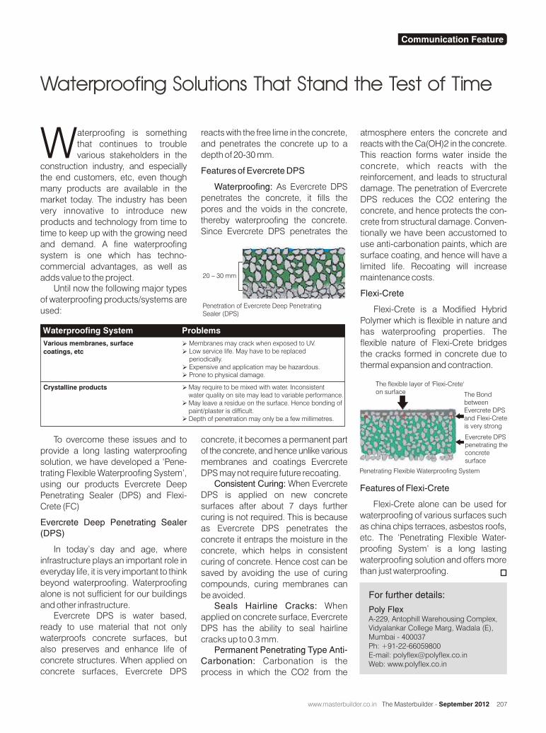


214 The Masterbuilder - September 2012 • www.masterbuilder.co.in
Double Skin Facades: Solution for Energy Efficient Building OperationsBhavani Balakrishna
Facade Double Skin
The building industry is one of the biggest consumers of energy across industries. Due to increasing concerns about depletion of fossil fuel reserves and
natural resources, the industry is constantly in the lookout for innovative building materials that can reduce the consumption of energy. One such promising invention is the Double Skin Facade (DSF). While DSFs have been used to a large extent in Europe for aesthetics and acoustics, a growing section of the building industry also believe that using DSFs in large buildings can improve the overall energy efficiency of a building by passive solar heat gain in winter, reducing thermal losses in winter, reducing overall solar heat gain (in summer) and support of natural ventilation (with the stack effect).

www.masterbuilder.co.in • The Masterbuilder - September 2012 215
Structure of a Double Skin Facade
The Belgium Building Research Institute describes the structure/layers of a Double Skin Façade System as the following
- An exterior glazing which is usually a hardened single glazing. This exterior façade can be fully glazed.
- An insulating interior double glazing unit. This could be clear, low E coating or solar control glazing. Generally, this layer is not completely glazed.
- The air cavity between the two panes - The width of the cavity can vary as a function of the applied concept between 200 mm to more than 2m. This width influences the way that the façade is maintained.
- The air cavity between the two panes can be totally natural, fan supported or mechanically ventilated. The five common ventilation modes are outdoor air curtain, indoor air curtain, air supply, air exhaust and buffer zone
- Automatically controlled solar shading is integrated inside the air cavity.The shading device is placed inside the cavity for protective reasons.
In most cases, the airflow through the glazing cavity is driven by natural buoyancy (hot air rises) aided by wind pressure differences,although some systems use small fans (often driven by photovoltaics). In hybrid systems, HVAC supply or exhaust air flows are directed through a glazing cavity before connecting with outside.Ventilated cavities may extend the height of the building, several stories, or be limited to a single storey.
DSFs can be categorized based on the type (geometry) of the cavity. In a box window type DSF, the horizontal and vertical partitioning divide the façade in smaller and independent boxes. In the shaft box type, a set of box window elements are placed inthe façade. These elements are connected
Facade Double Skin
What are Double Skin Facades?
Facades work as a building envelope – apart from lending character to the entire building, smart and innovative facades can provide significant energy savings. Innovations in glazing have already made heat absorbing glass, reflective glass and double glazing commonplace, with an associated set of aesthetic features. In the last few years, the architect and building community have been looking at combining these aesthetic elements with natural elements such as wind and climate along with intelligent mechanical solutions to make these facades more responsive to outdoor and indoor climates. Improved shading and solar control systems, greater use of automated controls, and integration with other building systems are some instances of such experimentation. The Double Skin Façade (DSF) is one example that can provide improved acoustics, better solar control and enhanced ventilation. The double skin facade incorporates the passive design strategies of natural ventilation, daylighting and solar heat gain into the fabric of the high-rise building.
A DSF typically has a pair of glass “skins” separated by an interstitial space – an air corridor or cavity. The air cavity between the layers of glass acts as insulation against temperature extremes, winds, and sound.
Sun-shading devices such as blinds (manual or automatic) are often located in the cavity between the two skins to prevent solar heat gains from entering the occupied space.On the external surface of glazing, vents are located top and bottom to prevent the void from overheating in the summer. In the winter, the vents are generally closed to trap heat in the void and reduce heat loss through the interior windows. In the mid-season condition, the inner curtain wall normally has operable windows for natural ventilation. An additional benefit is that modulating outer vents can be used to control the void temperature and thus extend the period suitable for natural ventilation.
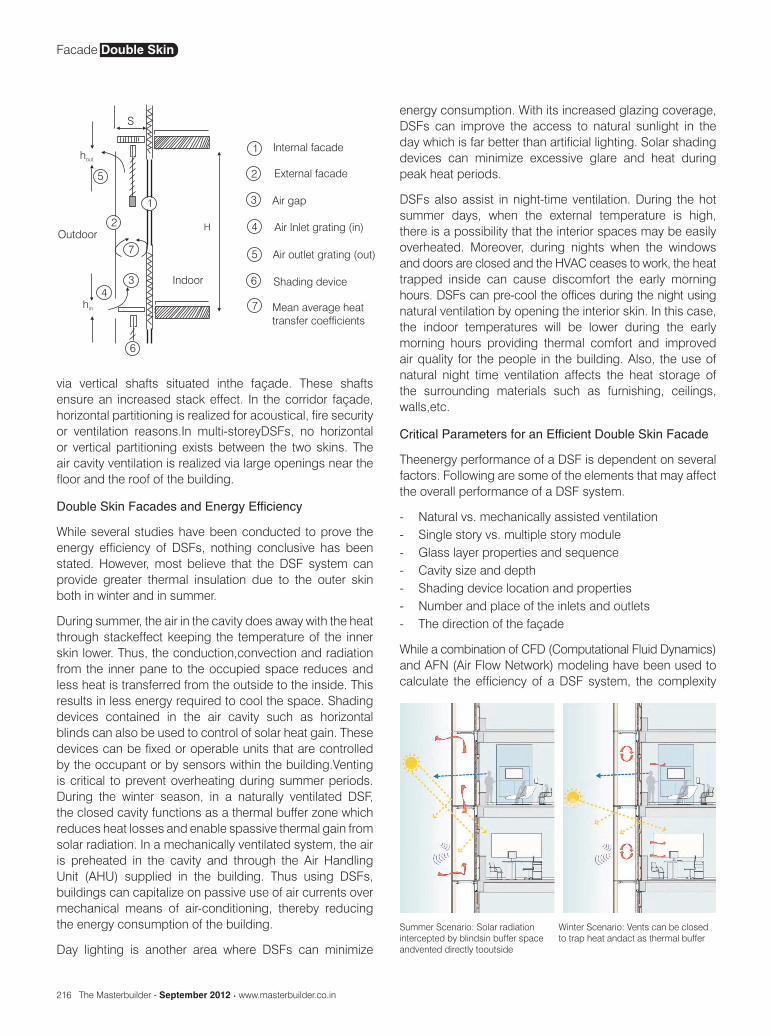
216 The Masterbuilder - September 2012 • www.masterbuilder.co.in
energy consumption. With its increased glazing coverage, DSFs can improve the access to natural sunlight in the day which is far better than artificial lighting. Solar shading devices can minimize excessive glare and heat during peak heat periods.
DSFs also assist in night-time ventilation. During the hot summer days, when the external temperature is high, there is a possibility that the interior spaces may be easily overheated. Moreover, during nights when the windows and doors are closed and the HVAC ceases to work, the heat trapped inside can cause discomfort the early morning hours. DSFs can pre-cool the offices during the night using natural ventilation by opening the interior skin. In this case, the indoor temperatures will be lower during the early morning hours providing thermal comfort and improved air quality for the people in the building. Also, the use of natural night time ventilation affects the heat storage of the surrounding materials such as furnishing, ceilings, walls,etc.
Critical Parameters for an Efficient Double Skin Facade
Theenergy performance of a DSF is dependent on several factors. Following are some of the elements that may affect the overall performance of a DSF system.
- Natural vs. mechanically assisted ventilation- Single story vs. multiple story module- Glass layer properties and sequence- Cavity size and depth- Shading device location and properties- Number and place of the inlets and outlets- The direction of the façade
While a combination of CFD (Computational Fluid Dynamics) and AFN (Air Flow Network) modeling have been used to calculate the efficiency of a DSF system, the complexity
Summer Scenario: Solar radiation intercepted by blindsin buffer space andvented directly tooutside
Winter Scenario: Vents can be closed to trap heat andact as thermal buffer
via vertical shafts situated inthe façade. These shafts ensure an increased stack effect. In the corridor façade, horizontal partitioning is realized for acoustical, fire security or ventilation reasons.In multi-storeyDSFs, no horizontal or vertical partitioning exists between the two skins. The air cavity ventilation is realized via large openings near the floor and the roof of the building.
Double Skin Facades and Energy Efficiency
While several studies have been conducted to prove the energy efficiency of DSFs, nothing conclusive has been stated. However, most believe that the DSF system can provide greater thermal insulation due to the outer skin both in winter and in summer.
During summer, the air in the cavity does away with the heat through stackeffect keeping the temperature of the inner skin lower. Thus, the conduction,convection and radiation from the inner pane to the occupied space reduces and less heat is transferred from the outside to the inside. This results in less energy required to cool the space. Shading devices contained in the air cavity such as horizontal blinds can also be used to control of solar heat gain. These devices can be fixed or operable units that are controlled by the occupant or by sensors within the building.Venting is critical to prevent overheating during summer periods.During the winter season, in a naturally ventilated DSF, the closed cavity functions as a thermal buffer zone which reduces heat losses and enable spassive thermal gain from solar radiation. In a mechanically ventilated system, the air is preheated in the cavity and through the Air Handling Unit (AHU) supplied in the building. Thus using DSFs, buildings can capitalize on passive use of air currents over mechanical means of air-conditioning, thereby reducing the energy consumption of the building.
Day lighting is another area where DSFs can minimize
Facade Double Skin


218 The Masterbuilder - September 2012 • www.masterbuilder.co.in
of different factors involved make it difficult to accurately predict the efficiency of a DSF.
Integrating an HVAC system with Double Skin Facades
There are now talks about how one can construct a “smart and intelligent building” that can integrate its HVAC/Building Management Systems (BMS) with the DSF to manipulate lighting, heating and ventilation requirements in the building. These could include windows and shading systems with optical and thermal properties that can dynamically change in response to climate and occupant preferences.These include motorized shades, switchable electrochromic or gasochromic window coatings.This combined with day lighting controls with 1-2 hour notification and pre-cooling of thermal mass using nighttime natural or mechanical ventilation through windows with 24-hour notification can significantly reduce cooling and lighting loads.
Executing a DSF System
Double-skin façades are significantly more expensive to install than conventional curtain wall systems considering only the cost of the installed façade.This is largely due to the engineering costs (mechanical and structural), the amount of special glass required, and the unfamiliarity of trades people with these systems thus leading to higher installation costs. If the design process fully integrates mechanical and architectural concerns from the beginning, these systems often require less mechanical (HVAC) systems and this also can compensate for the cost of the second façade.The design has also to take into account many different parameters connected both with the use of
building (building scheme and type, orientation, occupancy schedule, equipment etc.) and its location (climate, daylight availability, temperature, site & obstructions, latitude, atmo-spheric conditions etc.) before deciding on a DSF system
Conclusion
DSF was largely driven due to its aesthetics and acoustics. While there is a lot of speculation of about the performance of DSFs,based upon thermal performance analysis that have conducted so far,a double-skin façade perform better and provide some energy reduction, particularly on the heating side cycle, from a standard double glazed unit wall. However, nothing conclusive can be said as there are numerous parameters affecting the performance of a DSF.
References
- Tombazis A. N., (1996) on double elements in bioclimatic design in proceedings of 4thEuropean ConferenceSolar Energy in Architecture and Urban Planning,
- Saelens (2002) and E. Lee et al. (2002) in “High Performance CommercialBuilding Facades”
- Arons, D. (2000). Properties and Applications of Double-Skin BuildingFacades MSc thesis in Building Technology, Massachusetts Institute of Technology (MIT), USA
- Harrison and Boake, (2003) in the Tectonics of the Environmental Skin
- Li, D. H. W., and Lam, J. C. (2001) Evaluation of lighting performance in office buildings with day lighting controls
- www.jeffvaglio.com
Photo Courtesy
www.sydney-city.blogspot.in
Facade Double Skin


