42
The Material Point Method and its Uses in SCI Institute Related Research Projects Jim Guilkey With thanks to a whole lot of folks…
| Date post: | 21-Dec-2015 |
| Category: |
Documents |
| View: | 215 times |
| Download: | 1 times |
The Material Point Method and its Uses in SCI
Institute Related Research Projects
Jim Guilkey
With thanks to a whole lot of folks…
Outline
• Brief overview of the MPM algorithm
• SCI Related projects using MPM
• Algorithmic challenges
• Ongoing development
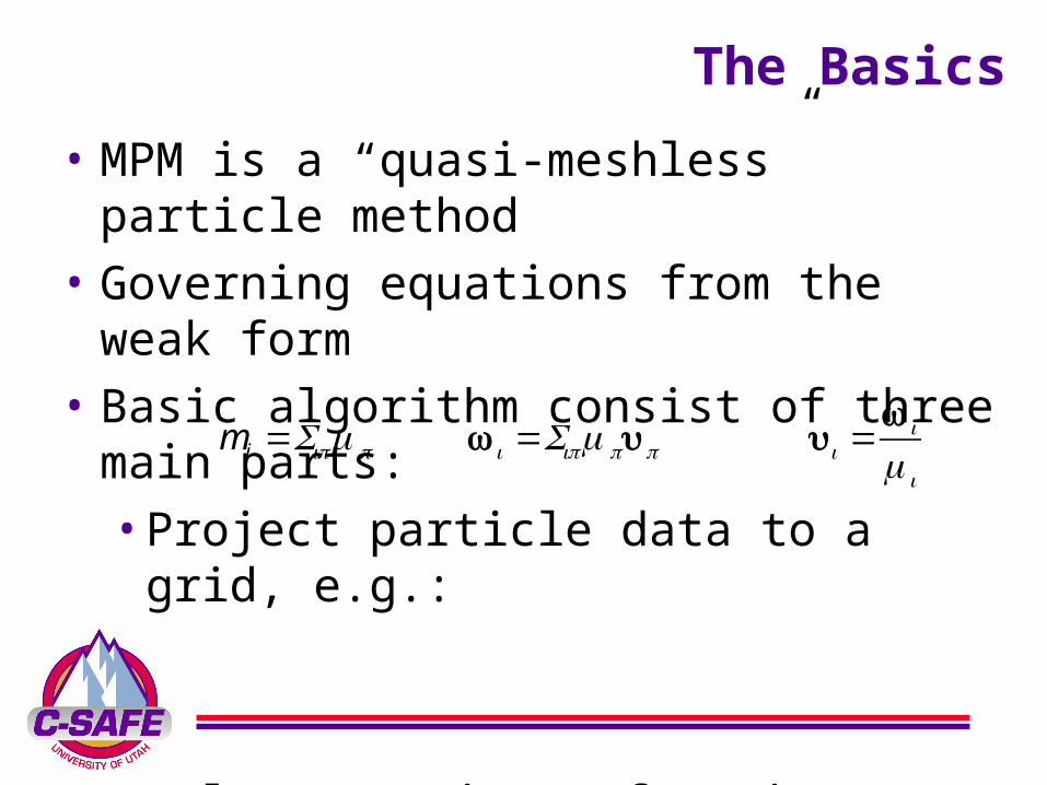
The Basics
• MPM is a “quasi-meshless” particle method
• Governing equations from the weak form
• Basic algorithm consist of three main parts:•Project particle data to a grid, e.g.:
•Solve equations of motion on the grid
•Update particles’ state based on changes of the nodal values
mi =Sipmp wi =Sipmpup ui =wi
mi

1. Discretize geometry with particles and define
an overlying computational grid. Particles
carry all state data (mass, vel, temp., etc.)
4. Particle positions/velocities updated incrementally from mesh solution.5. Discard deformed mesh.
Define new mesh and repeat
1
4
The Algorithm
2. Project particle state to nodes. Stress at particles computed based on gradient of the mesh velocity.
3. Divergence of particle stress gives an internal force on the nodes. Acceleration computed at nodes and integrated, giving updated mesh velocity and (in principal) position
5
2
3ai = finti + fexti( ) mi

MPM Features (the good ones)
• Discretization of complex
geometry is trivial
• Resetting the grid prevents
distortion issues
• Parallelization is
straightforward
• Contact is simple to implement
and fast• Particles interact via the grid, so cost is roughly linear in the number of particles
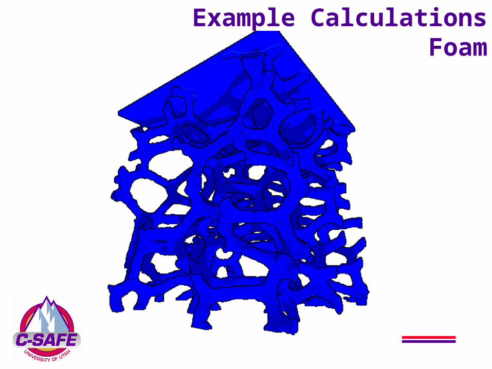
Example CalculationsFoam
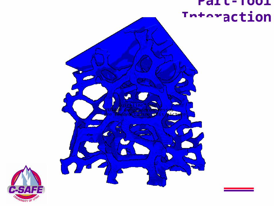
Part-Tool Interaction
QuickTime™ and aYUV420 codec decompressor
are needed to see this picture.
MPM in (or near) the SCI Institute
• C-SAFE (Parker, Berzins, Kirby,
et al.)
• Angiogenesis (Weiss)
• Virtual Soldier (Berzins, Kirby,
Johnson)
• Visualization•Ray Tracing (Parker, Bigler)•GPU Based Rendering
(Parker, Gribble, Stephenson)
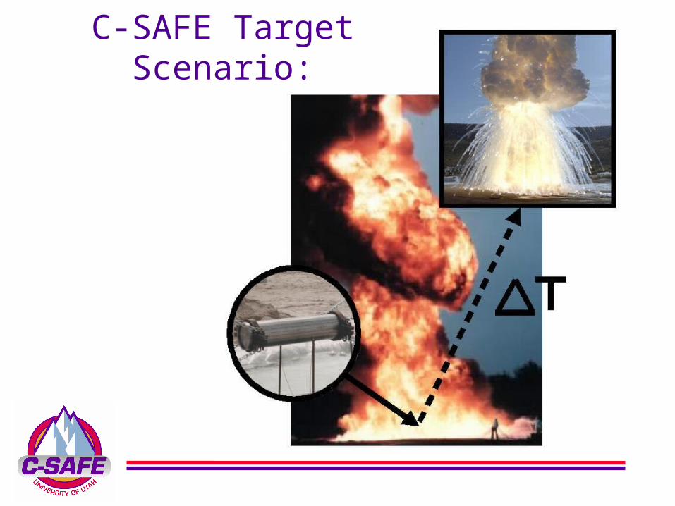
C-SAFE Target Scenario:
MPM Enhancements
• Incorporate MPM into a multi-material, compressible, finite volume CFD code
• One mesh for all material phases
• No surface tracking• Tightly coupled through a common pressure field and interaction terms in the governing equations

Common Reference Frame• ICE is a cell centered finite volume method• MPM uses particles and nodesTo establish a common frame of reference on one grid,solid phase data is projected to cell centers
Particle:Mass, volume,Temperature,Velocity, etc.
Node Centered:Mass, volume,Temperature,Velocity, etc.
Cell Centered:Density,Internal Energy,Momentum, etc.

Results
2003
QuickTime™ and aMotion JPEG A decompressor
are needed to see this picture.
Results 2005
QuickTime™ and aYUV420 codec decompressor
are needed to see this picture.
Span timescales separating calculation into three phase
• Run fire to “steady state”
• Use SS heat flux to compute heat conduction and thermal expansion in container
• Switch to full capability for explosion
Results 2005
Span length scaleswith AMR
• Run fire on a coarse level(s)
• Container at a fine level
• Still a ways to go here
Need to use both Strategies by Fall ‘06
QuickTime™ and aYUV420 codec decompressor
are needed to see this picture.

Angiogenesis and The Extracellular
MatrixDay 0
Day 4
Day 5

AngiogenesisMechanical Conditioning
By comparing the in vitro sprouting locations withthe computed stress field for a particular specimen, a
correlation between these phenomena can be found
Actuating Post
Fixed Anchor
Tensile Test AreaMedia
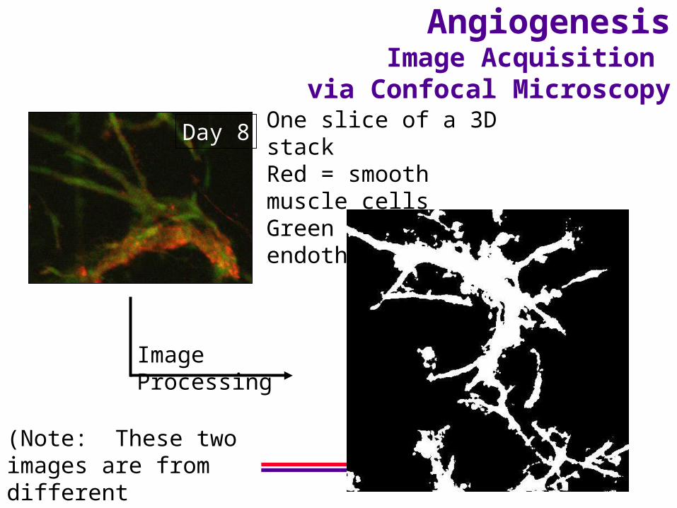
AngiogenesisImage Acquisition
via Confocal Microscopy
Day 8One slice of a 3D stackRed = smooth muscle cellsGreen = endothelial cells
Image Processing
(Note: These two images are from different datasets)
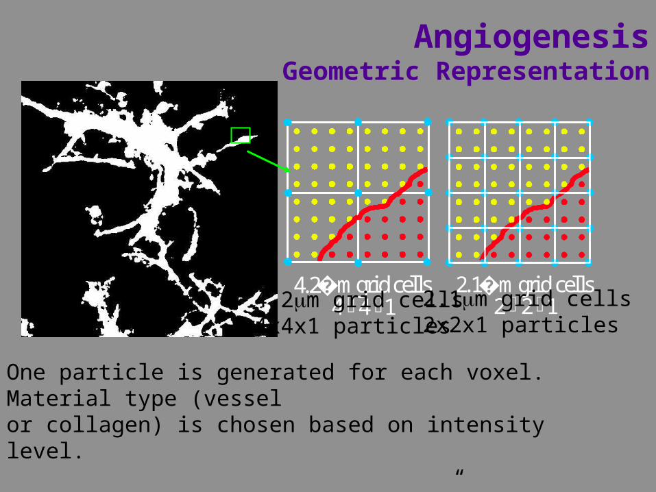
AngiogenesisGeometric Representation
4.2 �m grid cells4 4 1エ エ
2.1 �m grid cells2 2 1エ エ
8.4 �m grid cells8 8 1エ エ
One particle is generated for each voxel. Material type (vesselor collagen) is chosen based on intensity level.
For particle-based (aka “meshless” methods) creation of a suitablerepresentation is simple
4.2m grid cells4x4x1 particles
2.1m grid cells2x2x1 particles

AngiogenesisGeometric Representation
52 slices512 X 512 voxels each
525 m X 525 m X 52 m
QuickTime™ and aAnimation decompressor
are needed to see this picture.
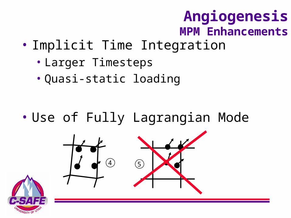
AngiogenesisMPM Enhancements
• Implicit Time Integration• Larger Timesteps• Quasi-static loading
• Use of Fully Lagrangian Mode
4 5

AngiogenesisWhy Fully Lagrangian?
QuickTime™ and aYUV420 codec decompressor
are needed to see this picture.
QuickTime™ and aYUV420 codec decompressor
are needed to see this picture.
QuickTime™ and aYUV420 codec decompressor
are needed to see this picture.
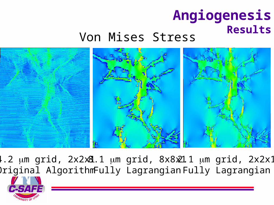
AngiogenesisResults
4.2 m grid, 2x2x1Original Algorithm
8.1 m grid, 8x8x1Fully Lagrangian
2.1 m grid, 2x2x1Fully Lagrangian
Von Mises Stress

AngiogenesisResults
Virtual SoldierWe need a medic!
• Simulations of projectile interactions with human tissue
• MPM Enhancements include:• Transversely isotropic material models
• Material failure models based on strain
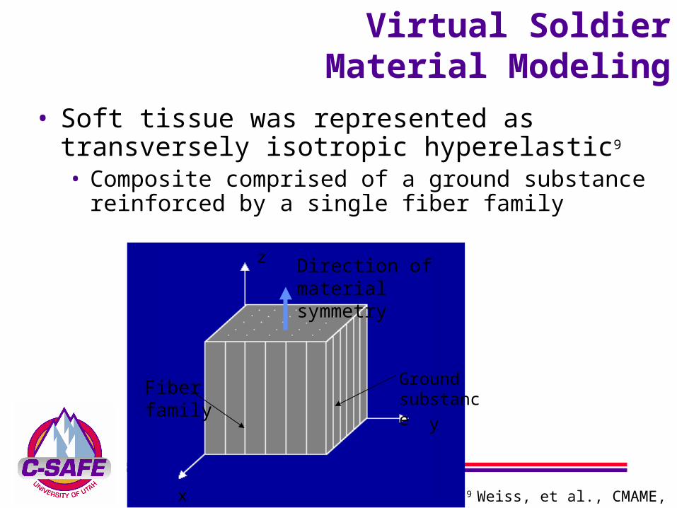
Virtual SoldierMaterial Modeling
Ground substance
x
y
z Direction of material symmetry
Fiber family
• Soft tissue was represented as transversely isotropic hyperelastic9
• Composite comprised of a ground substance reinforced by a single fiber family
9 Weiss, et al., CMAME, 1996

Virtual SoldierMaterial Modeling
• Modes of failure considered:
Matrix failure
Fiber failure
Total failure: both matrix and fibers have failed
Maximum Shear Criterion
Maximum Tensile Strain Criterion
> 50%
> 40%
σ fiber
σ volumetric σ matrix
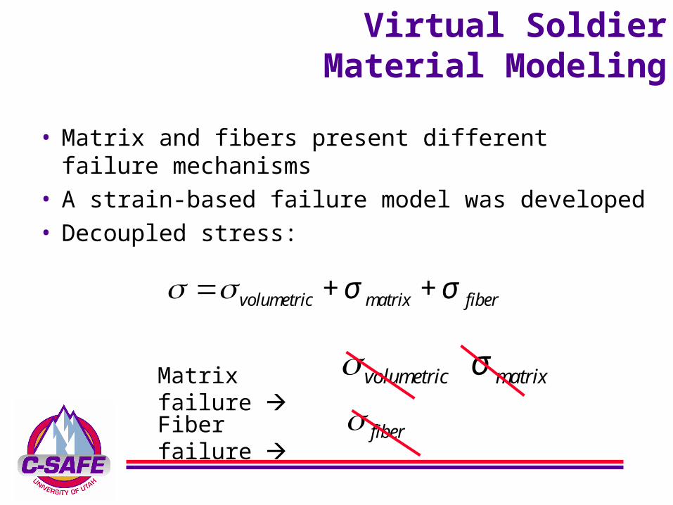
Virtual SoldierMaterial Modeling
• Matrix and fibers present different failure mechanisms
• A strain-based failure model was developed
• Decoupled stress:
Matrix failure
Fiber failure
σ =σ volumetric + σ matrix + σ fiber
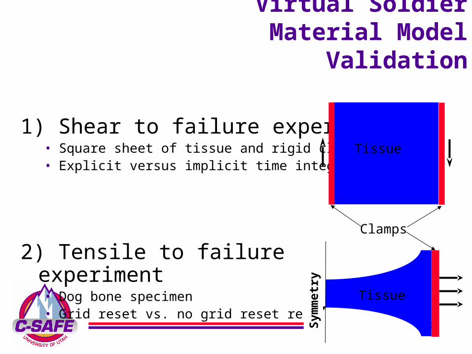
Virtual SoldierMaterial Model
Validation
1) Shear to failure experiment • Square sheet of tissue and rigid clamps • Explicit versus implicit time integration
2) Tensile to failure experiment• Dog bone specimen• Grid reset vs. no grid reset results
Tissue
Sym
met
ry p
lan
e
Tissue
Clamps
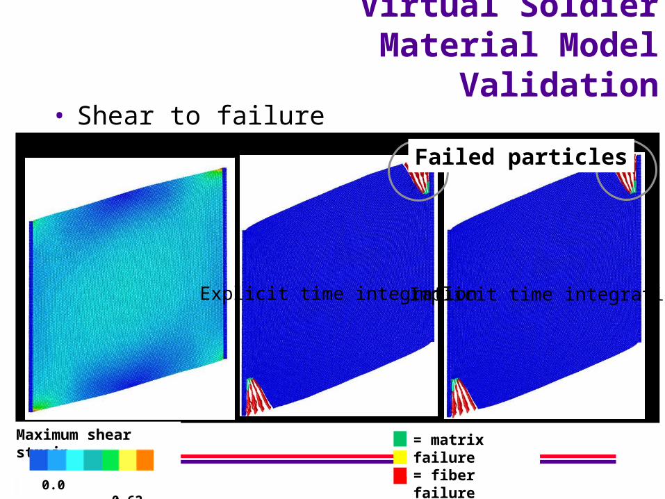
Virtual SoldierMaterial Model
Validation• Shear to failure
= matrix failure= fiber failure= total failure
Maximum shear strain
0.0 0.62
Explicit time integration Implicit time integration
Failed particles
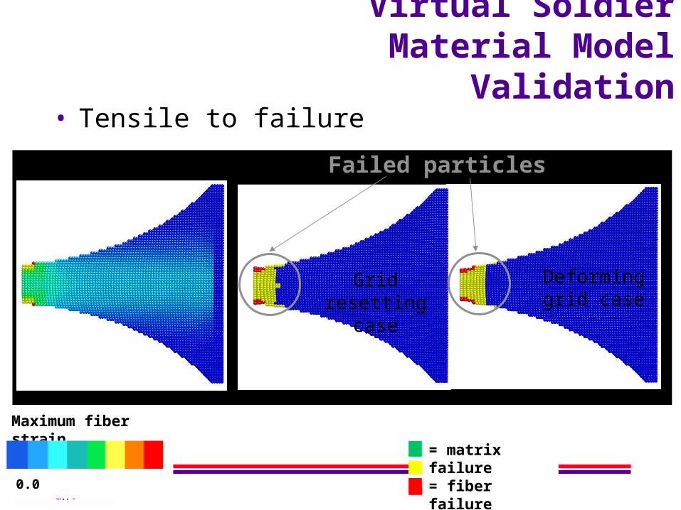
Virtual SoldierMaterial Model
Validation• Tensile to failure
= matrix failure= fiber failure= total failure
Maximum fiber strain
0.0 0.4
Failed particles
Grid resetting case
Deforming grid case
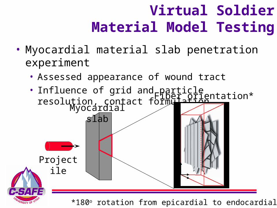
Virtual SoldierMaterial Model Testing
• Myocardial material slab penetration experiment • Assessed appearance of wound tract• Influence of grid and particle resolution, contact formulation
Projectile
Myocardial slabFiber orientation*
*180o rotation from epicardial to endocardial surface

Virtual SoldierMaterial Model Testing
• Frictional contact = 0.08
• Bullet speed 150 m/s
QuickTime™ and a decompressor
are needed to see this picture.

Virtual Soldier Model “Validation”
(aka Jeff and Mike go a huntin’)
Bullet entry wound
Heart

Virtual Soldier
Path Forward
fat layer
lungsheart
viscera hard tissue
fragment path
Torso Injury:

Particle Visualization
Ray TracingLocal Illumination Global Illumination
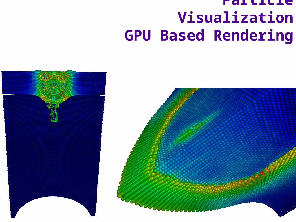
Particle Visualization
GPU Based Rendering

Conclusions• MPM offers an alternative to FEM for problems involving:
• Complex geometries
• Contact
• Material Failure
• Large Deformation
• MPM suffers from a number of numerical problems and lacks some of the theoretical underpinnings that support FEM
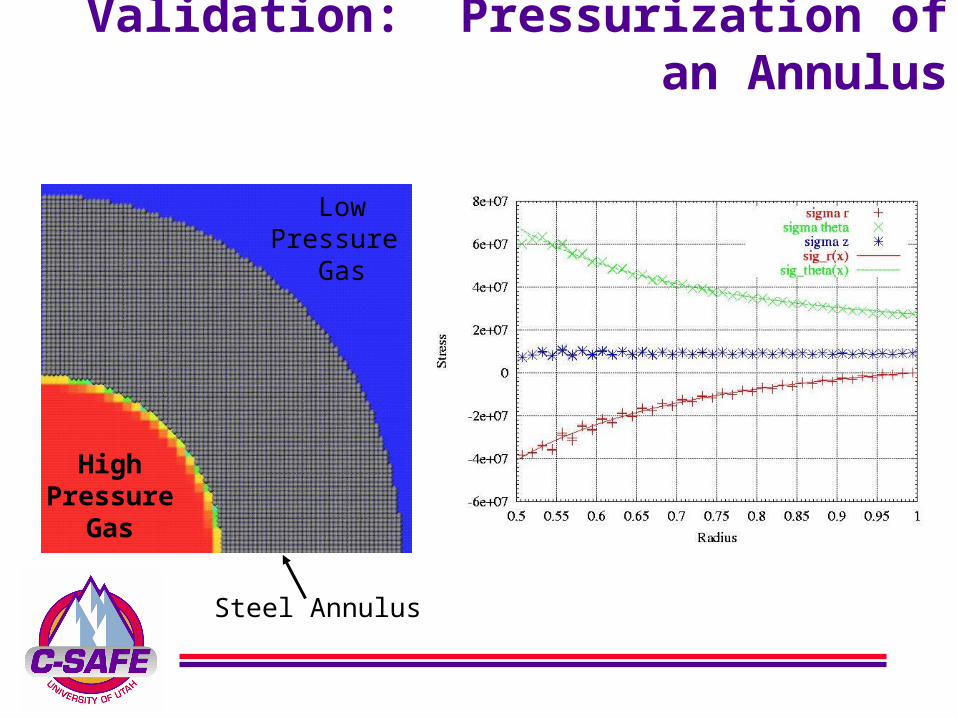
Validation: Pressurization of an Annulus
Steel Annulus
HighPressure
Gas
LowPressure
Gas
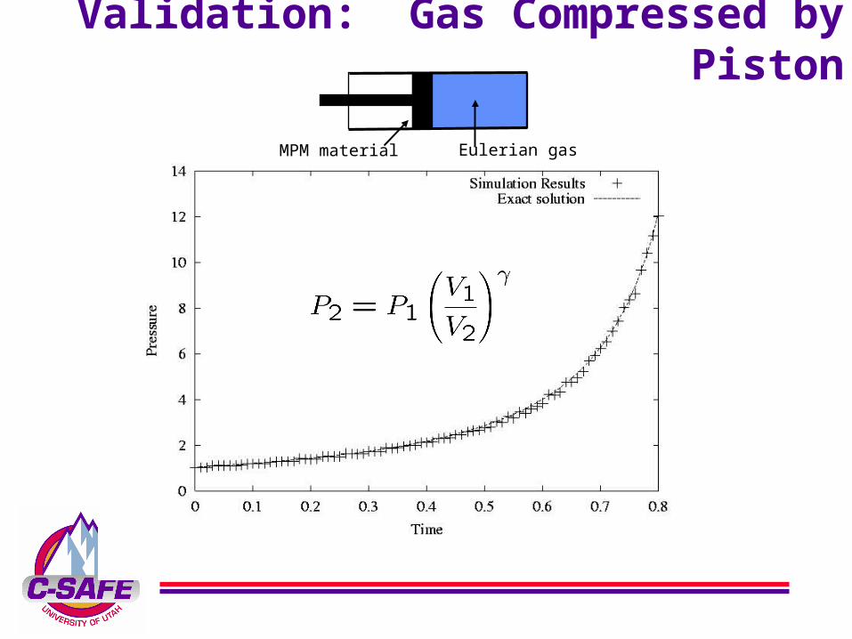
Validation: Gas Compressed by Piston
MPM material Eulerian gas
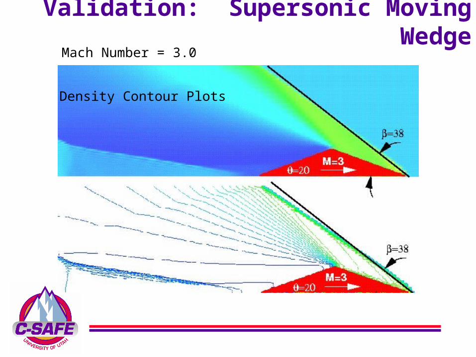
Validation: Supersonic Moving Wedge
Mach Number = 3.0
Density Contour Plots
Evolution of Heated Container, cont.
QuickTime™ and aMotion JPEG A decompressorare needed to see this picture.

Evolution of Heated Container, cont.
QuickTime™ and aPhoto - JPEG decompressorare needed to see this picture.


