The mechanical integrity of fuel pin cladding in a pulsed-beam accelerator driven subcritical reactor Ali Ahmad ⇑ , Geoffrey T. Parks Department of Engineering, University of Cambridge, Cambridge CB2 1PZ, United Kingdom article info Article history: Received 22 September 2011 Accepted 8 December 2011 Available online 5 January 2012 Keywords: Accelerator driven subcritical reactor Fixed field alternating gradient accelerator Pulsed-beam operation Thermal cyclic fatigue Fuel pin cladding integrity abstract The Accelerator Driven Subcritical Reactor (ADSR) is one of the reactor designs proposed for future nuclear energy production. Interest in the ADSR arises from its enhanced and intrinsic safety character- istics, as well as its potential ability to utilize the large global reserves of thorium and to burn legacy acti- nide waste from other reactors and decommissioned nuclear weapons. The ADSR concept is based on the coupling of a particle accelerator and a subcritical core by means of a neutron spallation target interface. One of the candidate accelerator technologies receiving increasing attention, the Fixed Field Alternating Gradient (FFAG) accelerator, generates a pulsed proton beam. This paper investigates the impact of pulsed proton beam operation on the mechanical integrity of the fuel pin cladding. A pulsed beam induces repetitive temperature changes in the reactor core which lead to cyclic thermal stresses in the cladding. To perform the thermal analysis aspects of this study a code that couples the neutron kinetics of a subcritical core to a cylindrical geometry heat transfer model was developed. This code, named PTS- ADS, enables temperature variations in the cladding to be calculated. These results are then used to per- form thermal fatigue analysis and to predict the stress-life behaviour of the cladding. Ó 2011 Elsevier Ltd. All rights reserved. 1. Introduction Accelerator Driven Subcritical Reactors (ADSR) are one of the possible future fission reactor systems under consideration that target sustainability, enhanced safety and economic competitive- ness. In addition, ADSRs can be used to incinerate problematic acti- nide waste and long-live radiotoxic fission products. Interest in ADSRs also arises from the possibility of deploying thorium in them. The use of thorium in an ADSR was first proposed by Bow- man (1998). Thorium is three to four times more abundant in nat- ure than uranium and under certain circumstances produces fewer minor actinides (International Atomic Energy Agency, 2005). The concept of an ADSR is based on the coupling of a particle accelerator that delivers a beam of protons of about 1 GeV energy to initiate spallation reactions in a heavy metal target and a sub- critical reactor fed by the spallation neutrons. The fact that the reactor core is inherently subcritical means that the reactor can be shut down simply by shutting off the accelerator. Among the accelerator technologies under consideration for deployment in an ADSR, the Fixed Field Alternating Gradient (FFAG) concept seems to be a promising candidate (Bungau et al., 2008). The FFAG offers better performance than a cyclotron in terms of its beam characteristics such as beam focusing and rapid acceleration (Mori, 2006). Moreover, FFAGs have a lower construction cost than linear accelerators (Takahashi, 2000). The FFAG was developed for rapid acceleration, which is ideal for systems requiring both high beam power and high repetition rates (Symon et al., 1956). An FFAG accelerator has already been coupled to a reactor core in Kyoto University Research Reactor Institute (KURRI) and studies of its performance conducted (Yamamoto and Shiroya, 2003; Tanigaki et al., 2006). An FFAG delivers accelerated protons in the form of discontinuous bunches, which in an ADSR would result in a pulsed spallation source. This, in turn, would lead to oscillations in the number of fission reactions within the subcritical core and there- fore in the core power. Temperatures in the core can, in conse- quence, also be expected to oscillate. This paper presents work done in coupling a fuel pin heat trans- fer model to a neutron kinetics model in order to study the dy- namic response of the fuel to pulsed-beam operation in an ADSR. This coupling was required to facilitate thermo-mechanical stress analyses, based on which the consequences of various accelerator beam transients can be quantified. The pulsed-beam delivery in FFAG accelerators will induce cyclic thermal stresses in the fuel pellets and cladding. This study focusses attention on the ther- mo-mechanical response of the fuel cladding as this is the barrier that prevents fission fragments from leaking into the coolant circuit. As long as the cladding maintains its integrity thermo- mechanical damage to the fuel pellets is of limited significance. The thermally induced stress variation in the cladding will determine the number of allowable cycles, both in normal 0306-4549/$ - see front matter Ó 2011 Elsevier Ltd. All rights reserved. doi:10.1016/j.anucene.2011.12.012 ⇑ Corresponding author. Tel.: +44 1223 748245; fax: +44 1223 332662. E-mail address: [email protected](A. Ahmad). Annals of Nuclear Energy 42 (2012) 35–42 Contents lists available at SciVerse ScienceDirect Annals of Nuclear Energy journal homepage: www.elsevier.com/locate/anucene
Transcript
Annals of Nuclear Energy 42 (2012) 35–42
Contents lists available at SciVerse ScienceDirect
The Accelerator Driven Subcritical Reactor (ADSR) is one of the reactor designs proposed for futurenuclear energy production. Interest in the ADSR arises from its enhanced and intrinsic safety character-istics, as well as its potential ability to utilize the large global reserves of thorium and to burn legacy acti-nide waste from other reactors and decommissioned nuclear weapons. The ADSR concept is based on thecoupling of a particle accelerator and a subcritical core by means of a neutron spallation target interface.One of the candidate accelerator technologies receiving increasing attention, the Fixed Field AlternatingGradient (FFAG) accelerator, generates a pulsed proton beam. This paper investigates the impact ofpulsed proton beam operation on the mechanical integrity of the fuel pin cladding. A pulsed beaminduces repetitive temperature changes in the reactor core which lead to cyclic thermal stresses in thecladding. To perform the thermal analysis aspects of this study a code that couples the neutron kineticsof a subcritical core to a cylindrical geometry heat transfer model was developed. This code, named PTS-ADS, enables temperature variations in the cladding to be calculated. These results are then used to per-form thermal fatigue analysis and to predict the stress-life behaviour of the cladding.
� 2011 Elsevier Ltd. All rights reserved.
1. Introduction
Accelerator Driven Subcritical Reactors (ADSR) are one of thepossible future fission reactor systems under consideration thattarget sustainability, enhanced safety and economic competitive-ness. In addition, ADSRs can be used to incinerate problematic acti-nide waste and long-live radiotoxic fission products. Interest inADSRs also arises from the possibility of deploying thorium inthem. The use of thorium in an ADSR was first proposed by Bow-man (1998). Thorium is three to four times more abundant in nat-ure than uranium and under certain circumstances produces fewerminor actinides (International Atomic Energy Agency, 2005).
The concept of an ADSR is based on the coupling of a particleaccelerator that delivers a beam of protons of about 1 GeV energyto initiate spallation reactions in a heavy metal target and a sub-critical reactor fed by the spallation neutrons. The fact that thereactor core is inherently subcritical means that the reactor canbe shut down simply by shutting off the accelerator. Among theaccelerator technologies under consideration for deployment inan ADSR, the Fixed Field Alternating Gradient (FFAG) conceptseems to be a promising candidate (Bungau et al., 2008). The FFAGoffers better performance than a cyclotron in terms of its beamcharacteristics such as beam focusing and rapid acceleration (Mori,
ll rights reserved.
: +44 1223 332662.
2006). Moreover, FFAGs have a lower construction cost than linearaccelerators (Takahashi, 2000). The FFAG was developed for rapidacceleration, which is ideal for systems requiring both high beampower and high repetition rates (Symon et al., 1956). An FFAGaccelerator has already been coupled to a reactor core in KyotoUniversity Research Reactor Institute (KURRI) and studies of itsperformance conducted (Yamamoto and Shiroya, 2003; Tanigakiet al., 2006). An FFAG delivers accelerated protons in the form ofdiscontinuous bunches, which in an ADSR would result in a pulsedspallation source. This, in turn, would lead to oscillations in thenumber of fission reactions within the subcritical core and there-fore in the core power. Temperatures in the core can, in conse-quence, also be expected to oscillate.
This paper presents work done in coupling a fuel pin heat trans-fer model to a neutron kinetics model in order to study the dy-namic response of the fuel to pulsed-beam operation in an ADSR.This coupling was required to facilitate thermo-mechanical stressanalyses, based on which the consequences of various acceleratorbeam transients can be quantified. The pulsed-beam delivery inFFAG accelerators will induce cyclic thermal stresses in the fuelpellets and cladding. This study focusses attention on the ther-mo-mechanical response of the fuel cladding as this is the barrierthat prevents fission fragments from leaking into the coolantcircuit. As long as the cladding maintains its integrity thermo-mechanical damage to the fuel pellets is of limited significance.The thermally induced stress variation in the cladding willdetermine the number of allowable cycles, both in normal
q coolant density (kg m�3)qc clad density (kg m�3)qf fuel density (kg m�3)ra stress amplituder0f fatigue strength coefficientA channel flow area (m2)b Basquin’s exponentCp coolant specific heat capacity (J kg�1 K�1)Cpc clad specific heat capacity (J kg�1 K�1)Cpf fuel specific heat capacity (J kg�1 K�1)hw clad-coolant heat transfer coefficient (W m�2 K�1)hg gap heat transfer coefficient (W m�2 K�1)K0 cyclic strength coefficientkc clad thermal conductivity (W K�1 m�1)kf fuel thermal conductivity (W K�1 m�1)
Kp fatigue plasticity coefficient_m coolant mass flow rate (kg s�1)
nc number of radial clad nodesnf number of radial fuel nodesq0 linear heat flux (W m�1)q00 surface heat flux (W m�2)q000 volume heat flux (W m�3)rc clad outer radius (m)rf fuel pellet outer radius (m)rg clad inner radius (m)Tb coolant bulk temperature (K)Tc clad outer surface temperature (K)
36 A. Ahmad, G.T. Parks / Annals of Nuclear Energy 42 (2012) 35–42
pulsed-beam operation and in the face of the larger transients in-duced by beam trips. The coupling between models of the reactorneutron kinetics and fuel pin heat transfer was achieved throughthe development of the PTS-ADS code. This code is described inthe next section.
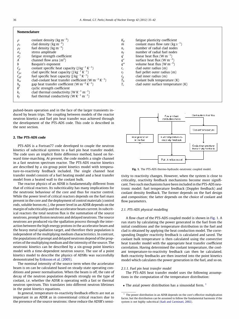
Fig. 1. The PTS-ADS thermo-hydraulic-neutronic coupled model.
1 The power distribution in an ADSR depends on the core’s effective multiplicationfactor, but the distribution can be assumed to follow the fundamental harmonic if thesystem is not highly subcritical (Kadi and Carminati, 2002).
2. The PTS-ADS code
PTS-ADS is a Fortran77 code developed to couple the neutronkinetics of subcritical systems to a fuel pin heat transfer model.The code uses an implicit finite difference method, based on for-ward time-marching. At present, the code models a single channelin a fast neutron spectrum reactor. The PTS-ADS reactor kineticsare described by a six-group point kinetics model with tempera-ture-to-reactivity feedback included. The single channel heattransfer model consists of a fuel heating model and a heat transfermodel from a heated wall to the coolant bulk.
The reactor physics of an ADSR is fundamentally different fromthat of critical reactors. Its subcriticality has many implications forthe neutronic behaviour of the core and thus for reactor control.While the power level of critical reactors depends on the fuel masspresent in the core and the deployment of control materials (controlrods, soluble boron etc.), the power level in an ADSR depends on themargin of subcriticality and the accelerator beam current. In subcrit-ical reactors the total neutron flux is the summation of the sourceneutrons, prompt fission neutrons and delayed neutrons. The sourceneutrons are produced via the spallation process through the inter-action between the high energy protons in the accelerator beam andthe heavy metal spallation target, and therefore their population isindependent of the multiplying medium characteristics. In contrast,the populations of prompt and delayed neutrons depend of the prop-erties of the multiplying medium and the intensity of the source. Theneutronic kinetics can be described by a six-group point kineticsmodel with a time-dependent neutron source. The use of a pointkinetics model to describe the physics of ADSRs was successfullydemonstrated by Eriksson et al. (2005).
The nominal intensity of the source term when the acceleratorbeam is on can be calculated based on steady-state operating con-ditions and power normalisation. When the beam is off, the rate ofdecay of the neutron population depends strongly on the type ofcoolant, i.e. whether the ADSR is operating with a fast or thermalneutron spectrum. This translates into different neutron lifetimesin the point kinetics equations.
In general, temperature-to-reactivity feedback effects are not asimportant in an ADSR as in conventional critical reactors due tothe presence of the source neutrons: these reduce the ADSR’s sensi-
tivity to reactivity changes. However, when the system is close tocriticality, reactivity feedback mechanisms become more signifi-cant. Two such mechanisms have been included in the PTS-ADS neu-tronic model: fuel temperature feedback (Doppler feedback) andcoolant density feedback. The former depends on the fuel designand composition; the latter depends on the choice of coolant andflow parameters.
2.1. PTS-ADS physical modelling
A flow chart of the PTS-ADS coupled model is shown in Fig. 1. Arun starts by calculating the power generated in the fuel from theinitial conditions and the temperature distribution in the fuel andclad is obtained by applying the heat conduction model. The corre-sponding Doppler reactivity feedback is calculated and saved. Thecoolant bulk temperature is then calculated using the convectiveheat transfer model with the appropriate heat transfer coefficientcorrelation. Having determined the coolant temperature, the cool-ant temperature-to-reactivity feedback can then be calculated.Both reactivity feedbacks are then inserted into the point kineticsmodel which calculates the power generation in the fuel, and so on.
2.1.1. Fuel pin heat transfer modelThe PTS-ADS heat transfer model uses the following assump-
tions in the computation of the temperature distribution:
� The axial power distribution has a sinusoidal form. 1
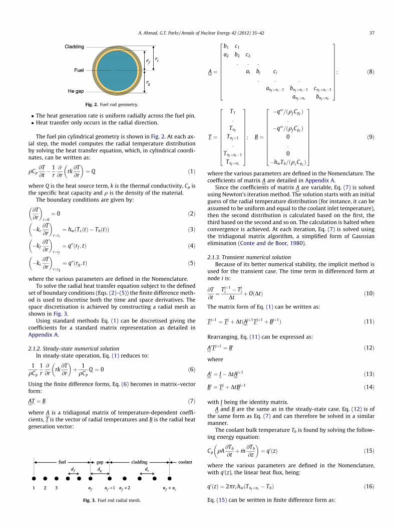
Fig. 2. Fuel rod geometry.
A. Ahmad, G.T. Parks / Annals of Nuclear Energy 42 (2012) 35–42 37
� The heat generation rate is uniform radially across the fuel pin.� Heat transfer only occurs in the radial direction.
The fuel pin cylindrical geometry is shown in Fig. 2. At each ax-ial step, the model computes the radial temperature distributionby solving the heat transfer equation, which, in cylindrical coordi-nates, can be written as:
qCp@T@t� 1
r@
@rrk@T@r
� �¼ Q ð1Þ
where Q is the heat source term, k is the thermal conductivity, Cp isthe specific heat capacity and q is the density of the material.
The boundary conditions are given by:
@T@r
� �r¼0¼ 0 ð2Þ
�kc@T@r
� �r¼rc
¼ hwðTcðtÞ � TbðtÞÞ ð3Þ
�kf@T@r
� �r¼rf
¼ q00ðrf ; tÞ ð4Þ
�kc@T@r
� �r¼rg
¼ q00ðrg ; tÞ ð5Þ
where the various parameters are defined in the Nomenclature.To solve the radial heat transfer equation subject to the defined
set of boundary conditions (Eqs. (2)–(5)) the finite difference meth-od is used to discretise both the time and space derivatives. Thespace discretisation is achieved by constructing a radial mesh asshown in Fig. 3.
Using standard methods Eq. (1) can be discretised giving thecoefficients for a standard matrix representation as detailed inAppendix A.
2.1.2. Steady-state numerical solutionIn steady-state operation, Eq. (1) reduces to:
1qCp
1r@
@rrk@T@r
� �þ 1
qCpQ ¼ 0 ð6Þ
Using the finite difference forms, Eq. (6) becomes in matrix–vectorform:
AT ¼ B ð7Þ
where A is a tridiagonal matrix of temperature-dependent coeffi-cients, T is the vector of radial temperatures and B is the radial heatgeneration vector:
Fig. 3. Fuel rod radial mesh.
A ¼
b1 c1
a2 b2 c2
: : :
ai bi ci
: : :
anfþnc�1 bnfþnc�1 cnfþnc�1
anfþnc bnfþnc
2666666666664
3777777777775
; ð8Þ
T ¼
T1
:
Tnf
Tnfþ1
:
Tnfþnc�1
Tnfþnc
2666666666664
3777777777775
; B ¼
�q000=ðqf CpfÞ
:
�q000=ðqf CpfÞ
0:
0�hwTb=ðqcCpc
Þ
2666666666664
3777777777775
ð9Þ
where the various parameters are defined in the Nomenclature. Thecoefficients of matrix A are detailed in Appendix A.
Since the coefficients of matrix A are variable, Eq. (7) is solvedusing Newton’s iteration method. The solution starts with an initialguess of the radial temperature distribution (for instance, it can beassumed to be uniform and equal to the coolant inlet temperature),then the second distribution is calculated based on the first, thethird based on the second and so on. The calculation is halted whenconvergence is achieved. At each iteration, Eq. (7) is solved usingthe tridiagonal matrix algorithm, a simplified form of Gaussianelimination (Conte and de Boor, 1980).
2.1.3. Transient numerical solutionBecause of its better numerical stability, the implicit method is
used for the transient case. The time term in differenced form atnode i is:
@T@t¼ Tjþ1
i � Tji
Dtþ OðDtÞ ð10Þ
The matrix form of Eq. (1) can be written as:
Tjþ1 ¼ Tj þ DtðAjþ1Tjþ1 þ Bjþ1Þ ð11Þ
Rearranging, Eq. (11) can be expressed as:
A0Tjþ1 ¼ B0 ð12Þ
where
A0 ¼ I � DtAjþ1 ð13Þ
B0 ¼ Tj þ DtBjþ1 ð14Þ
with I being the identity matrix.A and B are the same as in the steady-state case. Eq. (12) is of
the same form as Eq. (7) and can therefore be solved in a similarmanner.
The coolant bulk temperature Tb is found by solving the follow-ing energy equation:
Cp qA@Tb
@tþ _m
@Tb
@z
� �¼ q0ðzÞ ð15Þ
where the various parameters are defined in the Nomenclature,with q0(z), the linear heat flux, being:
q0ðzÞ ¼ 2prchwðTnfþnc � TbÞ ð16Þ
Eq. (15) can be written in finite difference form as:
38 A. Ahmad, G.T. Parks / Annals of Nuclear Energy 42 (2012) 35–42
CpqATjþ1
b;l � Tjb;l
Dt
" #þ Cp _m
Tjb;l � Tj
b;l�1
Dz
" #
¼ 2prchw Tjnfþnc ;l
� Tjb;l
� �ð17Þ
where l is the axial node index. Hence, rearranging Eq. (17):
Tjþ1b;l ¼Tj
b;lþDt2prchw
CpqATj
nfþnc ;l�Tj
b;l
� ��
_mqADz
Tjb;l�Tj
b;l�1
� �� �ð18Þ
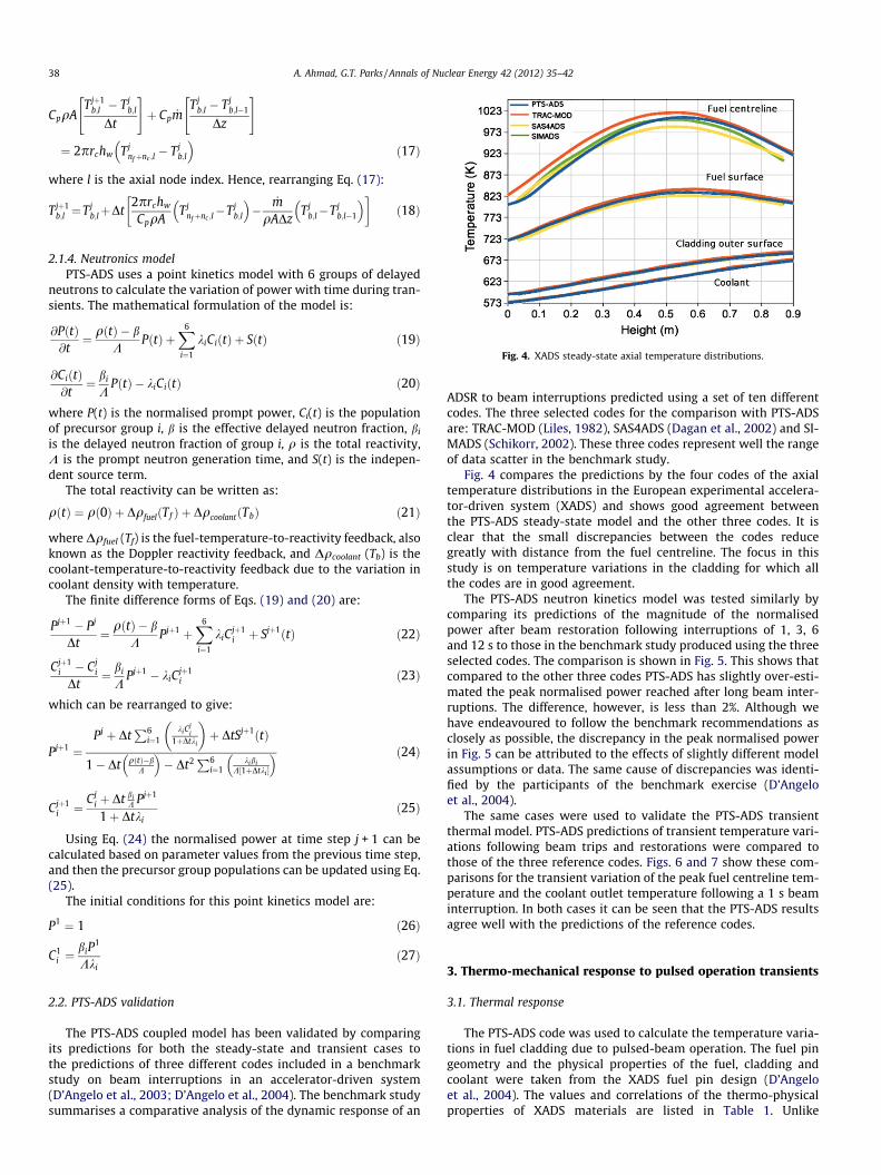
Fig. 4. XADS steady-state axial temperature distributions.
2.1.4. Neutronics modelPTS-ADS uses a point kinetics model with 6 groups of delayed
neutrons to calculate the variation of power with time during tran-sients. The mathematical formulation of the model is:
@PðtÞ@t¼ qðtÞ � b
KPðtÞ þ
X6
i¼1
kiCiðtÞ þ SðtÞ ð19Þ
@CiðtÞ@t
¼ bi
KPðtÞ � kiCiðtÞ ð20Þ
where P(t) is the normalised prompt power, Ci(t) is the populationof precursor group i, b is the effective delayed neutron fraction, bi
is the delayed neutron fraction of group i, q is the total reactivity,K is the prompt neutron generation time, and S(t) is the indepen-dent source term.
The total reactivity can be written as:
qðtÞ ¼ qð0Þ þ DqfuelðTf Þ þ DqcoolantðTbÞ ð21Þ
where Dqfuel (Tf) is the fuel-temperature-to-reactivity feedback, alsoknown as the Doppler reactivity feedback, and Dqcoolant (Tb) is thecoolant-temperature-to-reactivity feedback due to the variation incoolant density with temperature.
The finite difference forms of Eqs. (19) and (20) are:
Pjþ1 � Pj
Dt¼ qðtÞ � b
KPjþ1 þ
X6
i¼1
kiCjþ1i þ Sjþ1ðtÞ ð22Þ
Cjþ1i � Cj
i
Dt¼ bi
KPjþ1 � kiC
jþ1i ð23Þ
which can be rearranged to give:
Pjþ1 ¼Pj þ Dt
P6i¼1
kiCji
1þDtki
� �þ DtSjþ1ðtÞ
1� Dt qðtÞ�bK
� �� Dt2P6
i¼1kibi
K½1þDtki �
� � ð24Þ
Cjþ1i ¼
Cji þ Dt bi
K Pjþ1
1þ Dtkið25Þ
Using Eq. (24) the normalised power at time step j + 1 can becalculated based on parameter values from the previous time step,and then the precursor group populations can be updated using Eq.(25).
The initial conditions for this point kinetics model are:
P1 ¼ 1 ð26Þ
C1i ¼
biP1
Kkið27Þ
2.2. PTS-ADS validation
The PTS-ADS coupled model has been validated by comparingits predictions for both the steady-state and transient cases tothe predictions of three different codes included in a benchmarkstudy on beam interruptions in an accelerator-driven system(D’Angelo et al., 2003; D’Angelo et al., 2004). The benchmark studysummarises a comparative analysis of the dynamic response of an
ADSR to beam interruptions predicted using a set of ten differentcodes. The three selected codes for the comparison with PTS-ADSare: TRAC-MOD (Liles, 1982), SAS4ADS (Dagan et al., 2002) and SI-MADS (Schikorr, 2002). These three codes represent well the rangeof data scatter in the benchmark study.
Fig. 4 compares the predictions by the four codes of the axialtemperature distributions in the European experimental accelera-tor-driven system (XADS) and shows good agreement betweenthe PTS-ADS steady-state model and the other three codes. It isclear that the small discrepancies between the codes reducegreatly with distance from the fuel centreline. The focus in thisstudy is on temperature variations in the cladding for which allthe codes are in good agreement.
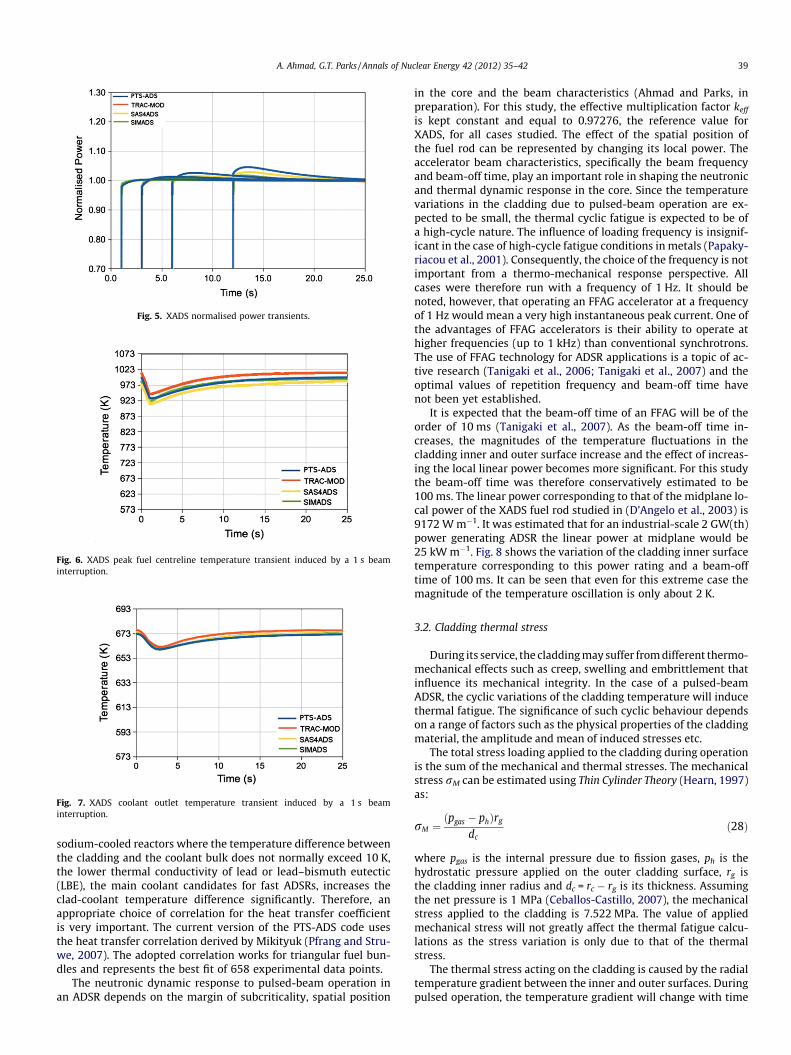
The PTS-ADS neutron kinetics model was tested similarly bycomparing its predictions of the magnitude of the normalisedpower after beam restoration following interruptions of 1, 3, 6and 12 s to those in the benchmark study produced using the threeselected codes. The comparison is shown in Fig. 5. This shows thatcompared to the other three codes PTS-ADS has slightly over-esti-mated the peak normalised power reached after long beam inter-ruptions. The difference, however, is less than 2%. Although wehave endeavoured to follow the benchmark recommendations asclosely as possible, the discrepancy in the peak normalised powerin Fig. 5 can be attributed to the effects of slightly different modelassumptions or data. The same cause of discrepancies was identi-fied by the participants of the benchmark exercise (D’Angeloet al., 2004).
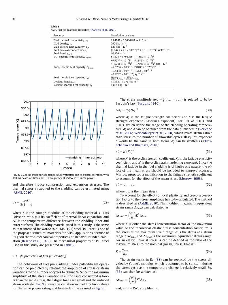
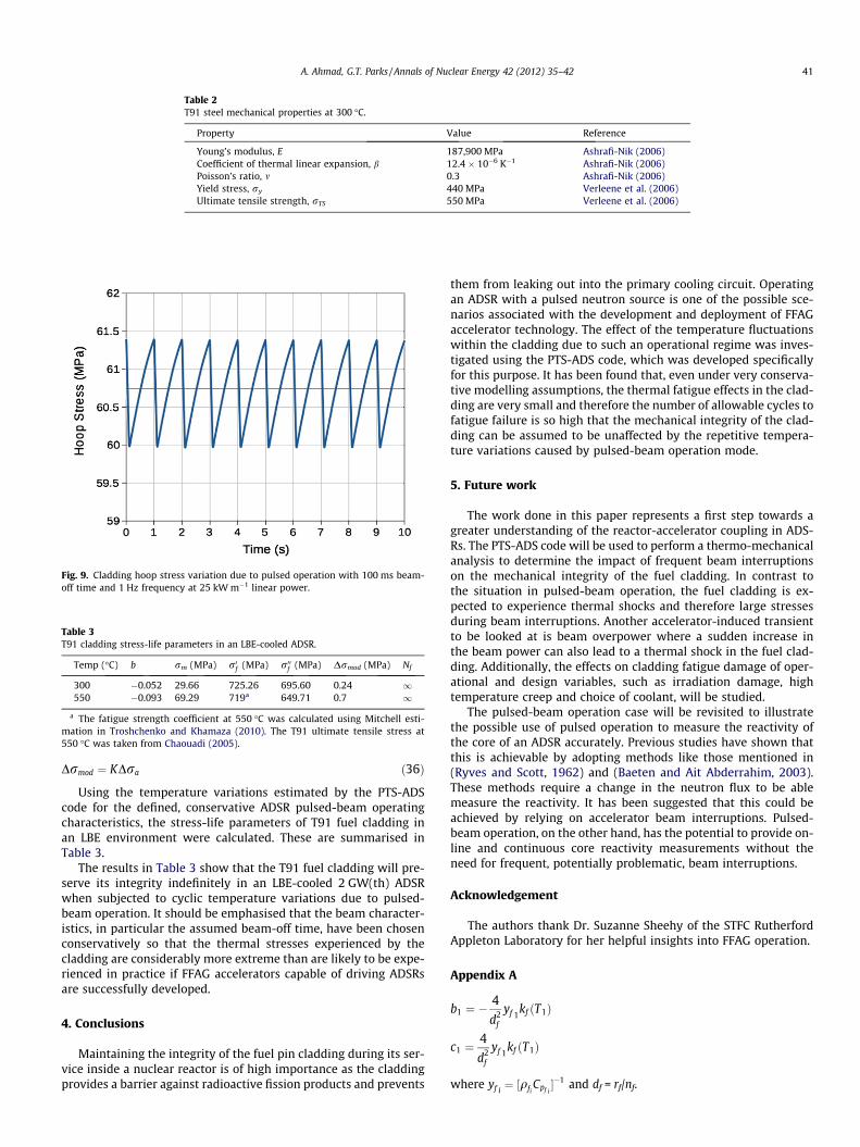
The same cases were used to validate the PTS-ADS transientthermal model. PTS-ADS predictions of transient temperature vari-ations following beam trips and restorations were compared tothose of the three reference codes. Figs. 6 and 7 show these com-parisons for the transient variation of the peak fuel centreline tem-perature and the coolant outlet temperature following a 1 s beaminterruption. In both cases it can be seen that the PTS-ADS resultsagree well with the predictions of the reference codes.
3. Thermo-mechanical response to pulsed operation transients
3.1. Thermal response
The PTS-ADS code was used to calculate the temperature varia-tions in fuel cladding due to pulsed-beam operation. The fuel pingeometry and the physical properties of the fuel, cladding andcoolant were taken from the XADS fuel pin design (D’Angeloet al., 2004). The values and correlations of the thermo-physicalproperties of XADS materials are listed in Table 1. Unlike
Fig. 5. XADS normalised power transients.
Fig. 6. XADS peak fuel centreline temperature transient induced by a 1 s beaminterruption.
Fig. 7. XADS coolant outlet temperature transient induced by a 1 s beaminterruption.
A. Ahmad, G.T. Parks / Annals of Nuclear Energy 42 (2012) 35–42 39
sodium-cooled reactors where the temperature difference betweenthe cladding and the coolant bulk does not normally exceed 10 K,the lower thermal conductivity of lead or lead–bismuth eutectic(LBE), the main coolant candidates for fast ADSRs, increases theclad-coolant temperature difference significantly. Therefore, anappropriate choice of correlation for the heat transfer coefficientis very important. The current version of the PTS-ADS code usesthe heat transfer correlation derived by Mikityuk (Pfrang and Stru-we, 2007). The adopted correlation works for triangular fuel bun-dles and represents the best fit of 658 experimental data points.
The neutronic dynamic response to pulsed-beam operation inan ADSR depends on the margin of subcriticality, spatial position
in the core and the beam characteristics (Ahmad and Parks, inpreparation). For this study, the effective multiplication factor keff
is kept constant and equal to 0.97276, the reference value forXADS, for all cases studied. The effect of the spatial position ofthe fuel rod can be represented by changing its local power. Theaccelerator beam characteristics, specifically the beam frequencyand beam-off time, play an important role in shaping the neutronicand thermal dynamic response in the core. Since the temperaturevariations in the cladding due to pulsed-beam operation are ex-pected to be small, the thermal cyclic fatigue is expected to be ofa high-cycle nature. The influence of loading frequency is insignif-icant in the case of high-cycle fatigue conditions in metals (Papaky-riacou et al., 2001). Consequently, the choice of the frequency is notimportant from a thermo-mechanical response perspective. Allcases were therefore run with a frequency of 1 Hz. It should benoted, however, that operating an FFAG accelerator at a frequencyof 1 Hz would mean a very high instantaneous peak current. One ofthe advantages of FFAG accelerators is their ability to operate athigher frequencies (up to 1 kHz) than conventional synchrotrons.The use of FFAG technology for ADSR applications is a topic of ac-tive research (Tanigaki et al., 2006; Tanigaki et al., 2007) and theoptimal values of repetition frequency and beam-off time havenot been yet established.
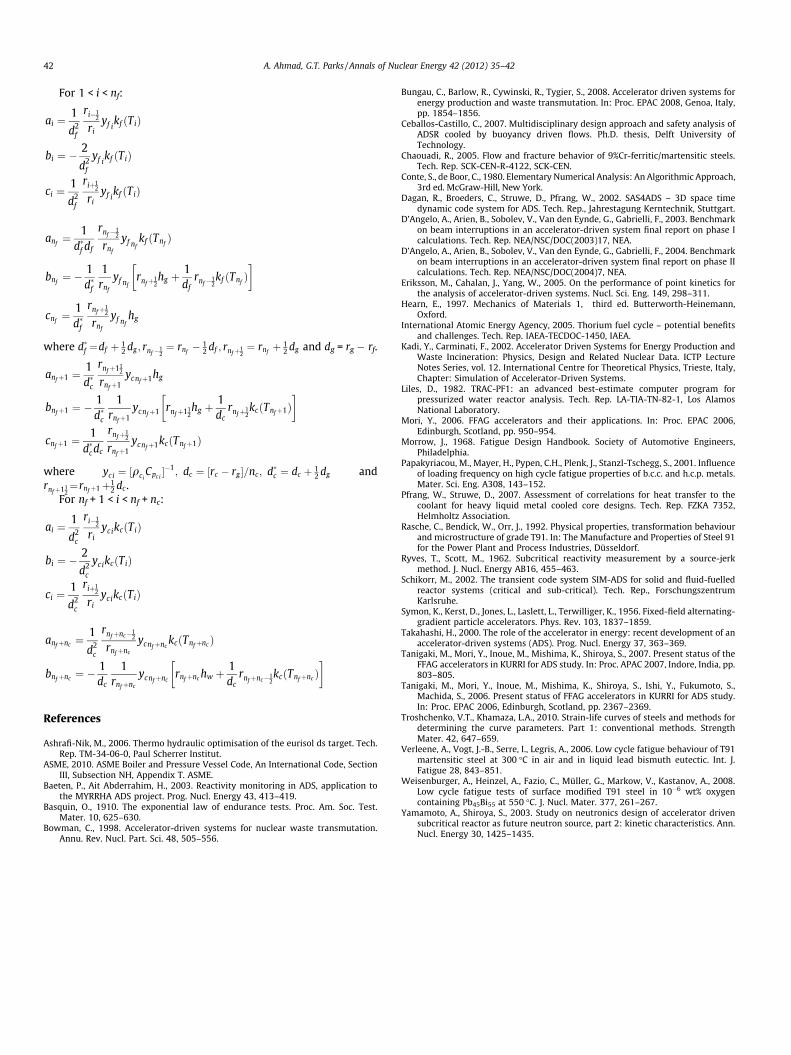
It is expected that the beam-off time of an FFAG will be of theorder of 10 ms (Tanigaki et al., 2007). As the beam-off time in-creases, the magnitudes of the temperature fluctuations in thecladding inner and outer surface increase and the effect of increas-ing the local linear power becomes more significant. For this studythe beam-off time was therefore conservatively estimated to be100 ms. The linear power corresponding to that of the midplane lo-cal power of the XADS fuel rod studied in (D’Angelo et al., 2003) is9172 W m�1. It was estimated that for an industrial-scale 2 GW(th)power generating ADSR the linear power at midplane would be25 kW m�1. Fig. 8 shows the variation of the cladding inner surfacetemperature corresponding to this power rating and a beam-offtime of 100 ms. It can be seen that even for this extreme case themagnitude of the temperature oscillation is only about 2 K.
3.2. Cladding thermal stress
During its service, the cladding may suffer from different thermo-mechanical effects such as creep, swelling and embrittlement thatinfluence its mechanical integrity. In the case of a pulsed-beamADSR, the cyclic variations of the cladding temperature will inducethermal fatigue. The significance of such cyclic behaviour dependson a range of factors such as the physical properties of the claddingmaterial, the amplitude and mean of induced stresses etc.
The total stress loading applied to the cladding during operationis the sum of the mechanical and thermal stresses. The mechanicalstress rM can be estimated using Thin Cylinder Theory (Hearn, 1997)as:
rM ¼ðpgas � phÞrg
dcð28Þ
where pgas is the internal pressure due to fission gases, ph is thehydrostatic pressure applied on the outer cladding surface, rg isthe cladding inner radius and dc = rc � rg is its thickness. Assumingthe net pressure is 1 MPa (Ceballos-Castillo, 2007), the mechanicalstress applied to the cladding is 7.522 MPa. The value of appliedmechanical stress will not greatly affect the thermal fatigue calcu-lations as the stress variation is only due to that of the thermalstress.
The thermal stress acting on the cladding is caused by the radialtemperature gradient between the inner and outer surfaces. Duringpulsed operation, the temperature gradient will change with time
Table 1XADS fuel pin material properties (D’Angelo et al., 2003).
Property Correlation or value
Clad thermal conductivity, kc 15.4767 + 0.003448T W K�1 m�1
Fuel specific heat capacity, Cpf214:65270:21 CpUO2
þ 55:56270:21 CpPuO2
Coolant density, q 11,112 � 1.375T kg m�3
Coolant specific heat capacity, Cp 146.5 J kg�1 K�1
Fig. 8. Cladding inner surface temperature variation due to pulsed operation with100 ms beam-off time and 1 Hz frequency at 25 kW m�1 linear power.
40 A. Ahmad, G.T. Parks / Annals of Nuclear Energy 42 (2012) 35–42
and therefore induce compression and expansion stresses. Thethermal stress rT applied to the cladding can be estimated using(ASME, 2010):
rT ¼EbDT
2ð1� mÞ ð29Þ
where E is the Young’s modulus of the cladding material, m is itsPoisson’s ratio, b is its coefficient of thermal linear expansion, andDT is the temperature difference between the cladding inner andouter surfaces. The cladding material used in this study is the sameas that intended for XADS: 9Cr-1Mo (T91) steel. T91 steel is one ofthe proposed structural materials for ADSR applications because ofits good thermo-mechanical properties and behaviour under irradi-ation (Rasche et al., 1992). The mechanical properties of T91 steelused in this study are presented in Table 2.
3.3. Life prediction of fuel pin cladding
The behaviour of fuel pin cladding under pulsed-beam opera-tion can be predicted by relating the amplitude of stress or strainvariations to the number of cycles to failure Nf. Since the maximumamplitude of the stress variation in all the cases considered is low-er than the yield stress, the fatigue loads are small and the inducedstrain is elastic. Fig. 9 shows the variation in cladding hoop stressfor the same power rating and beam-off time as used in Fig. 8.
The stress amplitude Dra ¼ 12 ðrmax � rminÞ is related to Nf by
Basquin’s law (Basquin, 1910):
Dra ¼ r0f ð2Nf Þb ð30Þ
where r0f is the fatigue strength coefficient and b is the fatiguestrength exponent (Basquin’s exponent). For T91 at 300 �C and550 �C which define the range of the cladding operating tempera-ture, r0f and b can be obtained from the data published in (Verleeneet al., 2006; Weisenburger et al., 2008) which relate strain ratherthan stress to the number of allowable cycles. Basquin’s exponentb would be the same in both forms. r0f can be written as (Tros-hchenko and Khamaza, 2010):
r0f ¼ K 0 Kp� n0 ð31Þ
where K0 is the cyclic strength coefficient, Kp is the fatigue plasticitycoefficient, and n0 is the cyclic strain hardening exponent. Since thethermal fatigue in the fuel cladding is of high-cycle nature, the ef-fect of the mean stress should be included to improve accuracy.Morrow proposed a modification to the fatigue strength coefficientto account for the effect of the mean stress (Morrow, 1968):
r00f ¼ r0f � rm ð32Þ
where rm is the mean stress.To account for the effects of local plasticity and creep, a correc-
tion factor to the stress amplitude has to be calculated. The methodis described in (ASME, 2010). The modified maximum equivalentstrain range D�mod can calculated as:
D�mod ¼r��r
� �K2D�max ð33Þ
where K is either the stress concentration factor or the maximumvalue of the theoretical elastic stress concentration factor, r⁄ isthe stress at the maximum strain range, �r is the stress at a strainrange KD�max, and D�max is the maximum equivalent strain range.For an elastic uniaxial stress, K can be defined as the ratio of themaximum stress to the nominal (mean) stress, that is:
K ¼ rmax
rmð34Þ
The strain terms in Eq. (33) can be replaced by the stress di-vided by Young’s modulus, which is assumed to be constant duringthe stress cycle as the temperature change is relatively small. Eq.(33) can then be written as:
Drmod ¼r��r
� �K2Dra ð35Þ
and, as �r ¼ Kr�, simplified to:
Table 2T91 steel mechanical properties at 300 �C.
Property Value Reference
Young’s modulus, E 187,900 MPa Ashrafi-Nik (2006)Coefficient of thermal linear expansion, b 12.4 � 10�6 K�1 Ashrafi-Nik (2006)Poisson’s ratio, m 0.3 Ashrafi-Nik (2006)Yield stress, ry 440 MPa Verleene et al. (2006)Ultimate tensile strength, rTS 550 MPa Verleene et al. (2006)
Fig. 9. Cladding hoop stress variation due to pulsed operation with 100 ms beam-off time and 1 Hz frequency at 25 kW m�1 linear power.
Table 3T91 cladding stress-life parameters in an LBE-cooled ADSR.
a The fatigue strength coefficient at 550 �C was calculated using Mitchell esti-mation in Troshchenko and Khamaza (2010). The T91 ultimate tensile stress at550 �C was taken from Chaouadi (2005).
A. Ahmad, G.T. Parks / Annals of Nuclear Energy 42 (2012) 35–42 41
Drmod ¼ KDra ð36Þ
Using the temperature variations estimated by the PTS-ADScode for the defined, conservative ADSR pulsed-beam operatingcharacteristics, the stress-life parameters of T91 fuel cladding inan LBE environment were calculated. These are summarised inTable 3.
The results in Table 3 show that the T91 fuel cladding will pre-serve its integrity indefinitely in an LBE-cooled 2 GW(th) ADSRwhen subjected to cyclic temperature variations due to pulsed-beam operation. It should be emphasised that the beam character-istics, in particular the assumed beam-off time, have been chosenconservatively so that the thermal stresses experienced by thecladding are considerably more extreme than are likely to be expe-rienced in practice if FFAG accelerators capable of driving ADSRsare successfully developed.
4. Conclusions
Maintaining the integrity of the fuel pin cladding during its ser-vice inside a nuclear reactor is of high importance as the claddingprovides a barrier against radioactive fission products and prevents
them from leaking out into the primary cooling circuit. Operatingan ADSR with a pulsed neutron source is one of the possible sce-narios associated with the development and deployment of FFAGaccelerator technology. The effect of the temperature fluctuationswithin the cladding due to such an operational regime was inves-tigated using the PTS-ADS code, which was developed specificallyfor this purpose. It has been found that, even under very conserva-tive modelling assumptions, the thermal fatigue effects in the clad-ding are very small and therefore the number of allowable cycles tofatigue failure is so high that the mechanical integrity of the clad-ding can be assumed to be unaffected by the repetitive tempera-ture variations caused by pulsed-beam operation mode.
5. Future work
The work done in this paper represents a first step towards agreater understanding of the reactor-accelerator coupling in ADS-Rs. The PTS-ADS code will be used to perform a thermo-mechanicalanalysis to determine the impact of frequent beam interruptionson the mechanical integrity of the fuel cladding. In contrast tothe situation in pulsed-beam operation, the fuel cladding is ex-pected to experience thermal shocks and therefore large stressesduring beam interruptions. Another accelerator-induced transientto be looked at is beam overpower where a sudden increase inthe beam power can also lead to a thermal shock in the fuel clad-ding. Additionally, the effects on cladding fatigue damage of oper-ational and design variables, such as irradiation damage, hightemperature creep and choice of coolant, will be studied.
The pulsed-beam operation case will be revisited to illustratethe possible use of pulsed operation to measure the reactivity ofthe core of an ADSR accurately. Previous studies have shown thatthis is achievable by adopting methods like those mentioned in(Ryves and Scott, 1962) and (Baeten and Ait Abderrahim, 2003).These methods require a change in the neutron flux to be ablemeasure the reactivity. It has been suggested that this could beachieved by relying on accelerator beam interruptions. Pulsed-beam operation, on the other hand, has the potential to provide on-line and continuous core reactivity measurements without theneed for frequent, potentially problematic, beam interruptions.
Acknowledgement
The authors thank Dr. Suzanne Sheehy of the STFC RutherfordAppleton Laboratory for her helpful insights into FFAG operation.
Appendix A
b1 ¼ �4
d2f
yf 1kf ðT1Þ
c1 ¼4
d2f
yf 1kf ðT1Þ
where yf i¼ ½qfi
Cpf i��1 and df = rf/nf.
42 A. Ahmad, G.T. Parks / Annals of Nuclear Energy 42 (2012) 35–42
For 1 < i < nf:
ai ¼1
d2f
ri�12
riyf i
kf ðTiÞ
bi ¼ �2
d2f
yf ikf ðTiÞ
ci ¼1
d2f
riþ12
riyf i
kf ðTiÞ
anf¼ 1
d�f df
rnf�12
rnf
yf nfkf ðTnf
Þ
bnf¼ � 1
d�f
1rnf
yf nfrnfþ1
2hg þ
1df
rnf�12kf ðTnf
Þ� �
cnf¼ 1
d�f
rnfþ12
rnf
yf nfhg
where d�f ¼df þ 12 dg ; rnf�1
2¼ rnf
� 12 df ; rnfþ1
2¼ rnf
þ 12 dg and dg = rg � rf.
anfþ1 ¼1d�c
rnfþ112
rnfþ1ycnfþ1hg
bnfþ1 ¼ �1d�c
1rnfþ1
ycnfþ1 rnfþ112hg þ
1dc
rnfþ12kcðTnfþ1Þ
� �
cnfþ1 ¼1
d�cdc
rnfþ12
rnfþ1ycnfþ1kcðTnfþ1Þ
where yci ¼ ½qciCpc i��1; dc ¼ ½rc � rg �=nc; d�c ¼ dc þ 1
2 dg andrnfþ11
2¼rnfþ1þ1
2 dc .For nf + 1 < i < nf + nc:
ai ¼1
d2c
ri�12
riycikcðTiÞ
bi ¼ �2
d2c
ycikcðTiÞ
ci ¼1
d2c
riþ12
riycikcðTiÞ
anfþnc ¼1
d2c
rnfþnc�12
rnfþnc
ycnfþnckcðTnfþnc Þ
bnfþnc ¼ �1dc
1rnfþnc
ycnfþncrnfþnc hw þ
1dc
rnfþnc�12kcðTnfþnc Þ
� �
References
Ashrafi-Nik, M., 2006. Thermo hydraulic optimisation of the eurisol ds target. Tech.Rep. TM-34-06-0, Paul Scherrer Institut.
ASME, 2010. ASME Boiler and Pressure Vessel Code, An International Code, SectionIII, Subsection NH, Appendix T. ASME.
Baeten, P., Ait Abderrahim, H., 2003. Reactivity monitoring in ADS, application tothe MYRRHA ADS project. Prog. Nucl. Energy 43, 413–419.
Basquin, O., 1910. The exponential law of endurance tests. Proc. Am. Soc. Test.Mater. 10, 625–630.
Bowman, C., 1998. Accelerator-driven systems for nuclear waste transmutation.Annu. Rev. Nucl. Part. Sci. 48, 505–556.
Bungau, C., Barlow, R., Cywinski, R., Tygier, S., 2008. Accelerator driven systems forenergy production and waste transmutation. In: Proc. EPAC 2008, Genoa, Italy,pp. 1854–1856.
Ceballos-Castillo, C., 2007. Multidisciplinary design approach and safety analysis ofADSR cooled by buoyancy driven flows. Ph.D. thesis, Delft University ofTechnology.
Chaouadi, R., 2005. Flow and fracture behavior of 9%Cr-ferritic/martensitic steels.Tech. Rep. SCK-CEN-R-4122, SCK-CEN.
Conte, S., de Boor, C., 1980. Elementary Numerical Analysis: An Algorithmic Approach,3rd ed. McGraw-Hill, New York.
Dagan, R., Broeders, C., Struwe, D., Pfrang, W., 2002. SAS4ADS – 3D space timedynamic code system for ADS. Tech. Rep., Jahrestagung Kerntechnik, Stuttgart.
D’Angelo, A., Arien, B., Sobolev, V., Van den Eynde, G., Gabrielli, F., 2003. Benchmarkon beam interruptions in an accelerator-driven system final report on phase Icalculations. Tech. Rep. NEA/NSC/DOC(2003)17, NEA.
D’Angelo, A., Arien, B., Sobolev, V., Van den Eynde, G., Gabrielli, F., 2004. Benchmarkon beam interruptions in an accelerator-driven system final report on phase IIcalculations. Tech. Rep. NEA/NSC/DOC(2004)7, NEA.
Eriksson, M., Cahalan, J., Yang, W., 2005. On the performance of point kinetics forthe analysis of accelerator-driven systems. Nucl. Sci. Eng. 149, 298–311.
Hearn, E., 1997. Mechanics of Materials 1, third ed. Butterworth-Heinemann,Oxford.
International Atomic Energy Agency, 2005. Thorium fuel cycle – potential benefitsand challenges. Tech. Rep. IAEA-TECDOC-1450, IAEA.
Kadi, Y., Carminati, F., 2002. Accelerator Driven Systems for Energy Production andWaste Incineration: Physics, Design and Related Nuclear Data. ICTP LectureNotes Series, vol. 12. International Centre for Theoretical Physics, Trieste, Italy,Chapter: Simulation of Accelerator-Driven Systems.
Liles, D., 1982. TRAC-PF1: an advanced best-estimate computer program forpressurized water reactor analysis. Tech. Rep. LA-TIA-TN-82-1, Los AlamosNational Laboratory.
Mori, Y., 2006. FFAG accelerators and their applications. In: Proc. EPAC 2006,Edinburgh, Scotland, pp. 950–954.
Morrow, J., 1968. Fatigue Design Handbook. Society of Automotive Engineers,Philadelphia.
Papakyriacou, M., Mayer, H., Pypen, C.H., Plenk, J., Stanzl-Tschegg, S., 2001. Influenceof loading frequency on high cycle fatigue properties of b.c.c. and h.c.p. metals.Mater. Sci. Eng. A308, 143–152.
Pfrang, W., Struwe, D., 2007. Assessment of correlations for heat transfer to thecoolant for heavy liquid metal cooled core designs. Tech. Rep. FZKA 7352,Helmholtz Association.
Rasche, C., Bendick, W., Orr, J., 1992. Physical properties, transformation behaviourand microstructure of grade T91. In: The Manufacture and Properties of Steel 91for the Power Plant and Process Industries, Düsseldorf.
Ryves, T., Scott, M., 1962. Subcritical reactivity measurement by a source-jerkmethod. J. Nucl. Energy AB16, 455–463.
Schikorr, M., 2002. The transient code system SIM-ADS for solid and fluid-fuelledreactor systems (critical and sub-critical). Tech. Rep., ForschungszentrumKarlsruhe.
Symon, K., Kerst, D., Jones, L., Laslett, L., Terwilliger, K., 1956. Fixed-field alternating-gradient particle accelerators. Phys. Rev. 103, 1837–1859.
Takahashi, H., 2000. The role of the accelerator in energy: recent development of anaccelerator-driven systems (ADS). Prog. Nucl. Energy 37, 363–369.
Tanigaki, M., Mori, Y., Inoue, M., Mishima, K., Shiroya, S., 2007. Present status of theFFAG accelerators in KURRI for ADS study. In: Proc. APAC 2007, Indore, India, pp.803–805.
Tanigaki, M., Mori, Y., Inoue, M., Mishima, K., Shiroya, S., Ishi, Y., Fukumoto, S.,Machida, S., 2006. Present status of FFAG accelerators in KURRI for ADS study.In: Proc. EPAC 2006, Edinburgh, Scotland, pp. 2367–2369.
Troshchenko, V.T., Khamaza, L.A., 2010. Strain-life curves of steels and methods fordetermining the curve parameters. Part 1: conventional methods. StrengthMater. 42, 647–659.
Verleene, A., Vogt, J.-B., Serre, I., Legris, A., 2006. Low cycle fatigue behaviour of T91martensitic steel at 300 �C in air and in liquid lead bismuth eutectic. Int. J.Fatigue 28, 843–851.
Weisenburger, A., Heinzel, A., Fazio, C., Müller, G., Markow, V., Kastanov, A., 2008.Low cycle fatigue tests of surface modified T91 steel in 10�6 wt% oxygencontaining Pb45Bi55 at 550 �C. J. Nucl. Mater. 377, 261–267.
Yamamoto, A., Shiroya, S., 2003. Study on neutronics design of accelerator drivensubcritical reactor as future neutron source, part 2: kinetic characteristics. Ann.Nucl. Energy 30, 1425–1435.