+ All Categories
Home > Documents > THE MERSEY GATEWAY PROJECT DELIVERY PHASE · the Mersey Gateway Project. EIA is required under...

THE MERSEY GATEWAY PROJECT DELIVERY PHASE · the Mersey Gateway Project. EIA is required under...

Date post: 11-Mar-2020
Category:
Upload: others
View: 12 times
Download: 2 times
Share this document with a friend
338
Report No. MG_REP_EIA_009 November 2011 Revision B ENVIRONMENTAL IMPACT ASSESSMENT CONTAMINATION OF SOILS, SEDIMENTS AND GROUNDWATER TECHNICAL ANNEX THE MERSEY GATEWAY PROJECT DELIVERY PHASE
Transcript

Report No. MG_REP_EIA_009

November 2011 Revision B

ENVIRONMENTAL IMPACT ASSESSMENT

CONTAMINATION OF SOILS, SEDIMENTS AND GROUNDWATER

TECHNICAL ANNEX

THE MERSEY GATEWAY PROJECT

DELIVERY PHASE

The Mersey Gateway Project Gifford

Contamination of Soils, Sediments and Groundwater

Technical Annex

Page i Report No. MG_REP_EIA_009

November 2011 Rev B

THE MERSEY GATEWAY PROJECT

ENVIRONMENTAL IMPACT ASSESSMENT

CONTAMINATION OF SOILS, SEDIMENTS AND GROUNDWATER

TECHNICAL ANNEX

C O N T E N T S

1. INTRODUCTION ................................................................................................................. 1

2. PROPOSED CONSTRUCTION WORKS ........................................................................... 3

3. PLANNING POLICY ......................................................................................................... 12

4. METHOD STATEMENT .................................................................................................... 30

5. REVIEW OF DESK STUDY INFORMATION ................................................................... 87

6. BASELINE ...................................................................................................................... 145

7. RISK ASSESSMENT ...................................................................................................... 242

8. MITIGATION AND ENHANCEMENT MEASURES........................................................ 271

9. MONITORING REQUIREMENTS ................................................................................... 307

10. SUMMARY ...................................................................................................................... 308

11. REFERENCES ................................................................................................................ 326

FIGURES

Figure 3.1 Group A and B Priority Sites: Widnes

Figure 3.2 Group A and B Priority Sites: Runcorn

Figure 3.3 Updated Priority Sites: Widnes

Figure 3.4 Updated Priority Sites: Astmoor Industrial Estate

Figure 4.1 Comparison of Results Obtained for Dissolved and Total Metal Analysis in

Groundwater

Figure 5.1 Groundwater Source Protection Zones

Figure 6.1 Variation in Groundwater Levels with Time for the Sherwood Sandstone in

Widnes

Figure 6.2 Variation in Groundwater Levels over Time for the Sherwood Sandstone in

Runcorn

Figure 6.3 Variation in Groundwater Level over Time for the Glacial Deposits

Figure 6.4 Variation in Groundwater Level over Time for the Estuarine Alluvium

Figure 6.5 Variation in Groundwater Level over Time for the Made Ground

Figure 6.6 Tidal Influence with Distance from the Estuary in Widnes

Figure 6.7 Concentrations of Conductivity, Sodium and Chloride in the Sherwood Sandstone

Figure 6.8 Conceptualisation of Scouring and Sediment Mixing

Figure 6.9 Comparison of 95th Percentile Metal Concentrations to ISQG and PEL

Figure 6.10 Comparison of 95th Percentile PAH Concentrations to ISQG and PEL

Figure 6.11 Variation in Metal Concentrations Over Time for Different Groundwater Horizons

Figure 6.12 Variation in Chlorinated Hydrocarbon Concentrations over Time in BH1003

The Mersey Gateway Project Gifford

Contamination of Soils, Sediments and Groundwater

Technical Annex

Page ii Report No. MG_REP_EIA_009

November 2011 Rev B

DRAWINGS

MG_REP_EIA_009/001 Site Location Plan

MG_REP_EIA_009/002 Reference Design

MG_REP_EIA_009/003 Mersey Gateway Project Areas

MG_REP_EIA_009/004 Gifford Exploratory Hole Location Plans Phase 1, 2 & 3

MG_REP_EIA_009/005 Gifford Exploratory Hole Location Plans Phase 4 & 4a

MG_REP_EIA_009/006 Gifford Exploratory Hole Location Plans Phase 5

MG_REP_EIA_009/007 Gifford Exploratory Hole Location Plans Phase 6 (Widnes)

MG_REP_EIA_009/008 Gifford Exploratory Hole Location Plans Phase 6 (Bridgewater Junction)

MG_REP_EIA_009/009 Gifford Exploratory Hole Location Plans Phase 6 (Central Expressway)

MG_REP_EIA_009/010 Monitoring Well Locations

MG_REP_EIA_009/011 Shallow Monitoring Well Installation

MG_REP_EIA_009/012 Deep Monitoring Well Installation

MG_REP_EIA_009/013 Extract from BGS Geological Map - Drift

MG_REP_EIA_009/014 Extract from BGS Geological Map - Solid

MG_REP_EIA_009/015 Extract from Environment Agency Groundwater Vulnerability Map

MG_REP_EIA_009/016 Former ICI Widnes Experimental Site Drainage Plan

MG_REP_EIA_009/017 Historical Exploratory Hole Location Plan

MG_REP_EIA_009/018 St Michaels Golf Course, Southern Route Geological Cross Section A-A

MG_REP_EIA_009/019 St Michaels Golf Course, Southern Route Geological Cross Section B-B

MG_REP_EIA_009/020 Ditton Junction to Victoria Interchange Geological Cross Section C-C

MG_REP_EIA_009/021 Anglo Blackwell to Gussion Transport Geological Cross Section C2-C2

MG_REP_EIA_009/022 Victoria Interchange to St Helens Canal Geological Cross Section D-D

MG_REP_EIA_009/023 Catalyst Trade Park North-South Geological Cross Section D2-D2

MG_REP_EIA_009/024 Catalyst Trade Park Southern Boundary Geological Cross Section D3-

D3

MG_REP_EIA_009/025 St Helens Canal to Widnes Warth, Geological Cross Section E-E

MG_REP_EIA_009/026 Mersey Estuary Geological Cross Section F-F

MG_REP_EIA_009/027 Runcorn Saltmarsh to Manchester Ship Canal Geological Cross Section

G-G

MG_REP_EIA_009/028 Manchester Ship Canal to Bridgewater Junction Geological Cross

Section H-H

MG_REP_EIA_009/029 Remote Junctions Central Expressway Geological Cross Section J-J

MG_REP_EIA_009/030 Remote Junctions Weston Link Junction and M56 Junction 12

Geological Cross Section K-K & L-L

MG_REP_EIA_009/031 Conceptual Ground Model Widnes

MG_REP_EIA_009/032 Conceptual Ground Model Runcorn

MG_REP_EIA_009/033 Groundwater Flow Direction in the Alluvium

MG_REP_EIA_009/034 Groundwater Flow Direction in the Sandstone

MG_REP_EIA_009/035 Exceedances of GAC for Arsenic in Soil

MG_REP_EIA_009/036 Exceedances of GAC for Lead in Soil

MG_REP_EIA_009/037 Soil pH

MG_REP_EIA_009/038 Exceedances of GAC for Water Soluble Sulphate in Soil

MG_REP_EIA_009/039 Sulphide Concentrations >50mg/kg in Soil

MG_REP_EIA_009/040 Concentrations of Ammoniacal Nitrogen in Soil

MG_REP_EIA_009/041 Total Petroleum Hydrocarbons above 50mg/kg in Soils

MG_REP_EIA_009/042 Tetrachloroethene Concentrations in Soil

MG_REP_EIA_009/043 Trichloroethene Concentrations in Soil

MG_REP_EIA_009/044 1,1,1-Trichloroethane Concentrations in Soil

MG_REP_EIA_009/045 1,2-Dichloroethane Concentrations in Soil

MG_REP_EIA_009/046 Chloroform Concentrations in Soils

MG_REP_EIA_009/047 Carbon Tetrachloride Concentrations in Soils

The Mersey Gateway Project Gifford

Contamination of Soils, Sediments and Groundwater

Technical Annex

Page iii Report No. MG_REP_EIA_009

November 2011 Rev B

MG_REP_EIA_009/048 Hexachlorobutadiene Concentrations in Soils

MG_REP_EIA_009/049 Hexachloroethane Concentrations in Soils

MG_REP_EIA_009/050 Exceedances of ISQG for Arsenic in Soils

MG_REP_EIA_009/051 Exceedances of ISQG for Cadmium in Soils

MG_REP_EIA_009/052 Exceedances of ISQG for Chromium in Soils

MG_REP_EIA_009/053 Exceedances of ISQG for Copper in Soils

MG_REP_EIA_009/054 Exceedances of ISQG for Lead in Soils

MG_REP_EIA_009/055 Exceedances of ISQG for Zinc in Soils

MG_REP_EIA_009/056 Elevated Concentrations of Arsenic in Groundwater

MG_REP_EIA_009/057 Elevated Concentrations of Iron in Groundwater

MG_REP_EIA_009/058 Elevated Concentrations of Vanadium in Groundwater

MG_REP_EIA_009/059 Elevated Concentrations of Zinc in Groundwater

MG_REP_EIA_009/060 Elevated Concentrations of Antimony in Groundwater

MG_REP_EIA_009/061 Elevated Concentrations of Cadmium in Groundwater

MG_REP_EIA_009/062 Elevated Concentrations of Copper in Groundwater

MG_REP_EIA_009/063 Elevated Concentrations of Mercury in Groundwater

MG_REP_EIA_009/064 Elevated Concentrations of Chromium in Groundwater

MG_REP_EIA_009/065 Elevated Concentrations of Lead in Groundwater

MG_REP_EIA_009/066 Elevated Concentrations of Nickel in Groundwater

MG_REP_EIA_009/067 pH Concentrations in Groundwater

MG_REP_EIA_009/068 Chloride Levels >40% above the Seawater Standard in Groundwater

MG_REP_EIA_009/069 Distribution of Ammonia in Groundwater

MG_REP_EIA_009/070 Benzene Concentrations above the EQS in Groundwater

MG_REP_EIA_009/071 Toluene Concentrations above the EQS in Groundwater

MG_REP_EIA_009/072 Xylene Concentrations above the EQS in Groundwater

MG_REP_EIA_009/073 Petroleum Hydrocarbons Exceeding DWS in Groundwater

MG_REP_EIA_009/074 Locations of LNAPL

MG_REP_EIA_009/075 Carbon Disulphide in Groundwater

MG_REP_EIA_009/076 1,2-Dichloroethane in Groundwater above the DWS

MG_REP_EIA_009/077 Sum of PCE and TCE Concentrations above the DWS in Groundwater

MG_REP_EIA_009/078 Carbon Tetrachloride Concentration above the DWS in Groundwater

MG_REP_EIA_009/079 Trihalomethane Concentrations above the DWS in Groundwater

MG_REP_EIA_009/080 Vinyl Chloride Concentrations above the DWS in Groundwater

MG_REP_EIA_009/081 1,1,1-Trichloroethane Concentrations above EQS in Groundwater

MG_REP_EIA_009/082 1,1,2-Trichloroethane Concentrations above EQS in Groundwater

MG_REP_EIA_009/083 1,2-Dichloroethane Concentrations above EQS in Groundwater

MG_REP_EIA_009/084 Carbon Tetrachloride Concentrations above EQS in Groundwater

MG_REP_EIA_009/085 Chloroform Exceeding Concentrations in Groundwater Exceeding EQS

in Groundwater

MG_REP_EIA_009/086 Hexachlorobutadiene Concentrations in Groundwater Exceeding EQS in

Groundwater

MG_REP_EIA_009/087 Tetrachloroethene in Groundwater Exceeding EQS in Groundwater

MG_REP_EIA_009/088 Trichloroethene in Groundwater Exceeding EQS in Groundwater

MG_REP_EIA_009/089 Free Phase DNAPL in Groundwater

MG_REP_EIA_009/090 PAH Exceeding 1.2µg/l in Groundwater

MG_REP_EIA_009/091 Total Pesticides in Groundwater

MG_REP_EIA_009/092 Soil PID Readings

MG_REP_EIA_009/093 Conceptual Site Model – St Michaels Golf Course

MG_REP_EIA_009/094 Conceptual Site Model – Gussion Transport

MG_REP_EIA_009/095 Conceptual Site Model – Catalyst Trade Park

MG_REP_EIA_009/096 Conceptual Site Model – Astmoor Industrial Estate and Wigg Island

The Mersey Gateway Project Gifford

Contamination of Soils, Sediments and Groundwater

Technical Annex

Page iv Report No. MG_REP_EIA_009

November 2011 Rev B

APPENDICES

Appendix A Halton Borough Council St Michaels Golf Course (North) Part IIA Determination

Appendix B Minutes of Meetings with Environment Agency and Local Authority Contaminated Land

Officer

Appendix C Reynolds Geoscience Geophysical Report

Appendix D BACTEC UXO Desk Top Threat Assessment

Appendix R BAE Systems Risk Assessment for UXO

Appendix S Radman Associates Documentary Review on Potential for Radiological Contamination

Appendix T Information on former Chemical Weapons Facility at Randle Island

Appendix E Norwest Holst Soil Engineering Ltd Report on a Ground Investigation for the New

Mersey Crossing Factual Report (Phase 1 & 2 Site Investigation)

Appendix F Geotechnics Ltd Runcorn Sands Site Investigation Factual Report (Phase 3)

Appendix G Soil Mechanics Phase 4 Site Investigation Factual Report

Appendix H Soil Mechanics Phase 4A Site Investigation Factual Report

Appendix I Fugro Seacore Phase 5 Marine Site Investigation Factual Report

Appendix J Soil Mechanics Phase 6 Site Investigation Factual Report

Appendix U AEG Phase 7 Site Investigation Factual Report

Appendix K Historical Ordnance Survey Maps and Envirocheck Reports

Appendix L Results of Chemical Testing

Appendix M Contamination Assessment Criteria

Appendix V Detailed Quantitative Risk Assessment for Controlled Waters

Appendix N Results of Groundwater Level Monitoring

Appendix O Results of Ground Gas Monitoring

Appendix P Review of Alternative Foundation Measures for Embankments

Appendix Q Preliminary Remediation Options Appraisal

The Mersey Gateway Project Gifford

Contamination of Soils, Sediments and Groundwater

Technical Annex

Page 1 Report No. MG_REP_EIA_009

November 2011 Rev B

1. INTRODUCTION

1.1.1 An Environmental Impact Assessment (EIA) was undertaken in 2008 to support the proposal for

the Mersey Gateway Project. EIA is required under European law by Council Directive

99/337/EEC and in United Kingdom law by a variety of legislation including the Town and

Country Planning (Environmental Impact Assessment) (England and Wales) Regulations 1999.

The site location plan is included as Drawing Number MG_REP_EIA_009/001.

1.1.2 As explained in Chapter 1 of the Further Application Environmental Statement the Council is

now advancing the Project including the Proposals to its delivery phase and in order to prepare

the Project for procurement of the Project Company and in response to consultation with the

Department for Transport, some modifications to the Reference Design proposals have been

made which are the subject of the Further Application. This Technical Annexe has been

updated to reflect these modificaitions.

1.1.3 This report forms provides technical environmental information to support and elaborate on the

Environmental Statement (ES). The ES summarises the outcome of the EIA process, which

included work to compile this document.

1.1.4 Information on historical land uses, environmental setting and previous investigations was

obtained for review. This information was used to design a series of site investigations within

the Project area (as defined by the ES) in order to identify the ground conditions and the

presence, or otherwise, of contamination.

1.1.5 This report presents the findings of the information review and site investigations and, in

particular comments on the ground conditions encountered. An assessment of the likely

significance of the contamination that was found was undertaken along with a review of

potentially viable mitigation measures. This report includes additional information arising from

research, monitoring, site investigation and assessment undertaken since the 2008

Environmental Statement (Orders ES), including data obtained for the Public Inquiry in 2009.

1.1.6 The work undertaken was intended to provide sufficient information to allow an assessment of

ground conditions and potential risks arising from contamination to be undertaken for the EIA

process. Further investigation will be required to provide design criteria and enable the design

and any mitigation measures to be finalised. This assessment enables the feasibility of

mitigation measures to be considered but not to conclude that a given solution is necessarily the

most appropriate. The information obtained has also formed the basis for the remedial

measures currently being developed as part of the advanced works.

1.1.7 The site investigations were undertaken as combined geotechnical and contaminated land

investigations. The overall approach to the investigation works has been in accordance with

BS5930 (1999) Code of Practice for Site Investigation (and amendments in 2010), and

BS10175 (2001) Code of Practice for the Investigation of Potentially Contaminated Sites (and

subsequent revision dated 2011) together with other relevant guidance. The work has been

undertaken with reasonable skill, care and diligence.

1.1.8 The assessment has been based on information obtained from exploratory holes located at

positions based on information obtained on the history of the study area, the proposals for the

Mersey Gateway Project including the Proposals and the standards current at the time each

phase of investigation was designed. However, ground conditions are only known in detail at

each exploratory hole location. The conditions between holes have been interpolated and,

therefore, the actual nature of the ground may differ from the interpretation in this document.

Similarly, chemical analysis has only been undertaken on samples recovered at the exploratory

The Mersey Gateway Project Gifford

Contamination of Soils, Sediments and Groundwater

Technical Annex

Page 2 Report No. MG_REP_EIA_009

November 2011 Rev B

hole positions and it is possible that further areas of contamination are present between the

exploratory holes. This approach is entirely appropriate for an assessment of this nature.

1.1.9 In line with current UK best practice the contamination assessments made in this report are risk

based and the proposed end uses on which these are based are defined in the report. If

proposals for the project change or alternative construction methods are proposed then the

levels of risk and impacts outlined in this report could vary.

1.1.10 The findings and opinions in this report are based upon information derived from a variety of

sources that can reasonably be assumed to be reliable. Information has been derived from the

public register using various databases that allow data to be accessed quickly and cost

effectively. Information sources for the database include the Environment Agency and other

statutory authorities.

1.1.11 It will be necessary for the findings of this report to be reviewed prior to construction

commencing to ensure that they remain valid. Whilst the levels of most soil contaminants are

unlikely to change significantly, the potential remains for there to be changes in the

concentrations of contaminants in groundwater over time. This will ensure that the mitigation

measures being deployed remain appropriate. In order to reflect this, a programme of

groundwater monitoring has been carried out. This has been updated by monitoring of key

wells as part of the preparation of the Further Applications ES.

The Mersey Gateway Project Gifford

Contamination of Soils, Sediments and Groundwater

Technical Annex

Page 3 Report No. MG_REP_EIA_009

November 2011 Rev B

2. PROPOSED CONSTRUCTION WORKS

2.1 Introduction

2.1.1 This section provides a review of the construction proposals and methods with particular

referene to where these require consideration of ground conditions.

2.1.2 Detailed information on construction proposals is contained within the Mersey Gateway Project

Construction Methods Report which is appended to Chapter 2 of the Environmental Statement.

The following text has been updated to include amendments from the Construction Methods

Report prepared for the Further Applications ES (referred to as the Project including the

Proposals), concluding with a summary of the residual effects following mitigation.

2.1.3 The proposals under the Further Applications can be summarised as follows:

a. Adoption of Open Road Tolling Technology from opening, as opposed the barrier tolling

authorised by the Permissions and Orders;

b. Redesign of the on and off slips at the formerly proposed Widnes Loops Junction to

remove the loops configuration from the proposals and provide a grade separated

roundabout junction;

c. Changes to the vertical alignment of the mainline of the Project as a result of other design

changes;

d. Adjustments to the alignment at Lodge Lane Junction to remove the need to replace the

existing busway bridge; and

e. Adoption of urban highways standards in some locations where rural standards had been

used.

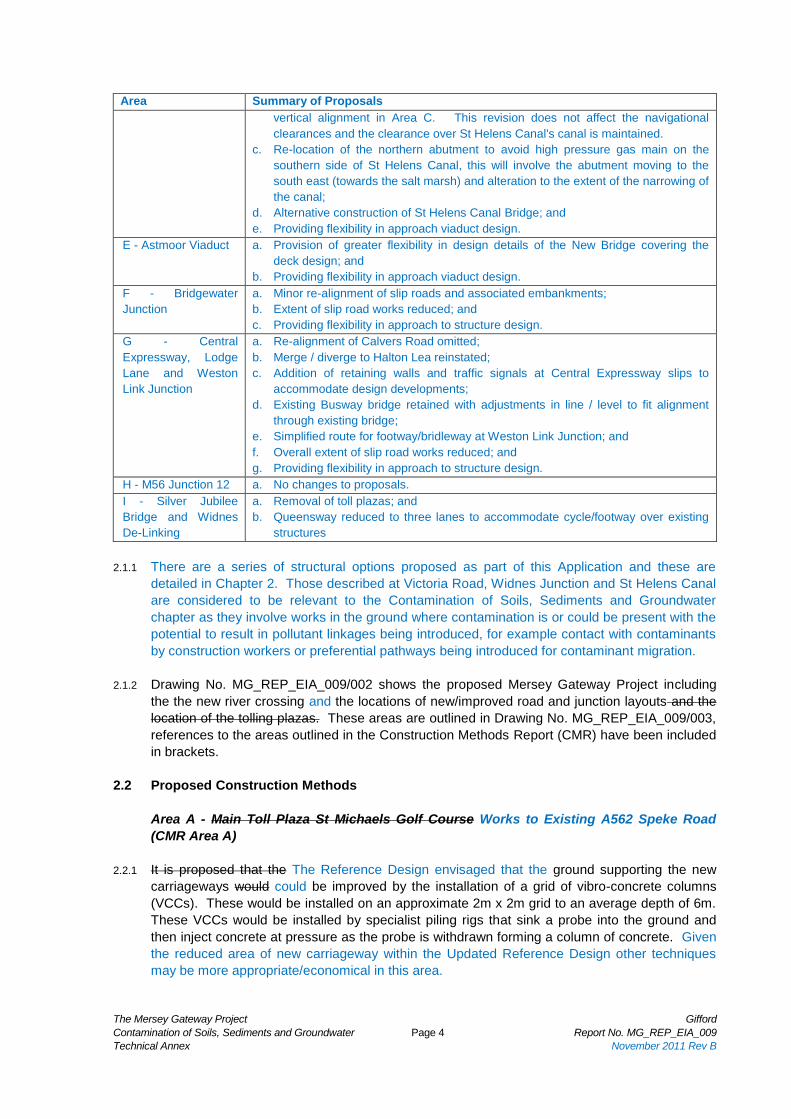
2.1.4 A description of the Proposals is provided in Chapter 2 of the ES: those relevant to

Contamination of Soils, Sediments and Groundwater are summarised in the following table:

Area Summary of Proposals

A – Speke Road a. Toll plazas removed;

b. Extent of overall works reduced to reflect removal of toll plazas;

c. Slip roads and embankments re-designed to reflect removal of toll plaza, low

retaining wall added on northern off slip; and

d. The reduced extent of the works means there will be no requirement for any

works that might affect either Stewards Brook or the Old Lane Subway.

B - Ditton Junction to

Freight Line

a. Toll plazas removed;

b. Slip roads and embankments re-designed to reflect removal of toll plazas;

c. Main alignment shifted north to reduce adverse effects during construction in

terms of disruption to road users; and

d. Providing flexibility in approach to structure design

C - Freight Line to St

Helens Canal

including the Widnes

Loops Junction

a. Toll plazas removed;

b. Junction, slip road and embankments re-designed (as roundabout) to reflect the

removal of the toll plazas;

c. Alternative construction of embankment / structures at Victoria Road;

d. Revisions to the alignment to take account of the changes including a reduction in

the vertical alignment and moving of the horizontal alignment to the south; and

e. Providing flexibility in approach to structure design.

D - Mersey Gateway

Bridge

a. Provision of greater flexibility in design details of the New Bridge covering the

deck design and cable arrangements including removal of potential provision for

future light rapid transit;

b. Revision to the northern abutment and the New bridge to tie into the lower

The Mersey Gateway Project Gifford

Contamination of Soils, Sediments and Groundwater

Technical Annex

Page 4 Report No. MG_REP_EIA_009

November 2011 Rev B

Area Summary of Proposals

vertical alignment in Area C. This revision does not affect the navigational

clearances and the clearance over St Helens Canal's canal is maintained.

c. Re-location of the northern abutment to avoid high pressure gas main on the

southern side of St Helens Canal, this will involve the abutment moving to the

south east (towards the salt marsh) and alteration to the extent of the narrowing of

the canal;

d. Alternative construction of St Helens Canal Bridge; and

e. Providing flexibility in approach viaduct design.

E - Astmoor Viaduct a. Provision of greater flexibility in design details of the New Bridge covering the

deck design; and

b. Providing flexibility in approach viaduct design.

F - Bridgewater

Junction

a. Minor re-alignment of slip roads and associated embankments;

b. Extent of slip road works reduced; and

c. Providing flexibility in approach to structure design.

G - Central

Expressway, Lodge

Lane and Weston

Link Junction

a. Re-alignment of Calvers Road omitted;

b. Merge / diverge to Halton Lea reinstated;

c. Addition of retaining walls and traffic signals at Central Expressway slips to

accommodate design developments;

d. Existing Busway bridge retained with adjustments in line / level to fit alignment

through existing bridge;

e. Simplified route for footway/bridleway at Weston Link Junction; and

f. Overall extent of slip road works reduced; and

g. Providing flexibility in approach to structure design.

H - M56 Junction 12 a. No changes to proposals.

I - Silver Jubilee

Bridge and Widnes

De-Linking

a. Removal of toll plazas; and

b. Queensway reduced to three lanes to accommodate cycle/footway over existing

structures

2.1.1 There are a series of structural options proposed as part of this Application and these are

detailed in Chapter 2. Those described at Victoria Road, Widnes Junction and St Helens Canal

are considered to be relevant to the Contamination of Soils, Sediments and Groundwater

chapter as they involve works in the ground where contamination is or could be present with the

potential to result in pollutant linkages being introduced, for example contact with contaminants

by construction workers or preferential pathways being introduced for contaminant migration.

2.1.2 Drawing No. MG_REP_EIA_009/002 shows the proposed Mersey Gateway Project including

the the new river crossing and the locations of new/improved road and junction layouts and the

location of the tolling plazas. These areas are outlined in Drawing No. MG_REP_EIA_009/003,

references to the areas outlined in the Construction Methods Report (CMR) have been included

in brackets.

2.2 Proposed Construction Methods

Area A - Main Toll Plaza St Michaels Golf Course Works to Existing A562 Speke Road

(CMR Area A)

2.2.1 It is proposed that the The Reference Design envisaged that the ground supporting the new

carriageways would could be improved by the installation of a grid of vibro-concrete columns

(VCCs). These would be installed on an approximate 2m x 2m grid to an average depth of 6m.

These VCCs would be installed by specialist piling rigs that sink a probe into the ground and

then inject concrete at pressure as the probe is withdrawn forming a column of concrete. Given

the reduced area of new carriageway within the Updated Reference Design other techniques

may be more appropriate/economical in this area.

The Mersey Gateway Project Gifford

Contamination of Soils, Sediments and Groundwater

Technical Annex

Page 5 Report No. MG_REP_EIA_009

November 2011 Rev B

2.2.2 The resulting grid of VCCs would could be overlain by a load transfer platform comprising

geosynthetics and imported granular fill material.

2.2.3 The carriageway pavement could be constructed directly on top of this granular capping layer.

Because of anticipated near surface ground contamination, a strip of the existing topsoil is not

envisaged.

2.2.4 A low reinforced concrete retaining wall will be constructed alongside the eastbound offslip to

avoid the widening to the north. The wall will be a maximum of 2m high.

2.2.5 The construction of culvert extensions for Stewards Brook would involve some excavation of

potentially contaminated material.

2.2.6 The toll plaza area would require a drainage system to carry rainwater to the balancing ponds.

This would include concrete drainage channels on either side of the main carriageway; these

would be formed in situ with minimal excavation. Two balancing ponds would be formed to the

south of the new carriageway on either side of Stewards Brook to control the drainage water

outfall flow rate into the brook. This water would not be allowed to drain into the ground. A

drainage system to carry surface water run-off to the drainage outfalls will be required. This

could include concrete drainage channels on either side of the main carriageway which could be

formed in-situ with minimal excavation. A kerb gully system could be considered although this

would require more excavation.

2.2.7 New services would be required for the new tolling facilities.

2.2.8 Finishing works would include street lighting, road signs and gantries, construction of the tolling

booths and associated facilities. and the erection of the tolling canopies potentially requiring

excavations for the installation of foundations. It is understood there will be no tunnel access to

the toll booths. This text has been removed as the proposed construction works no longer

include toll booths.

2.2.9 Area A includes part of the southern section of St Michaels Golf Course. The extent of the

permanent works in Area A is small, however, it has been included in this assessment on the

basis this area could be used as a construction compound.

Areas B1 to B2 - Ditton Junction to Freight Line (CMR Area B)

2.2.10 The proposed bridge at Ditton Junction would be a conventional structure and the deck could be

in concrete or steel/concrete composite of either in-situ or precast construction. The

foundations for the new bridge at the Ditton Junction would either be piled or on a combined

system of spread foundations and ground improvement. The pile caps or spread foundations

would be below finished ground level and would require excavation and the construction of

reinforced concrete elements. The abutment walls and wing walls would be of reinforced

concrete.

2.2.11 The new carriageway will be constructed on the embankment. A drainage system to carry

surface water run-off to the attenuation measures in the vicinity of the proposed Ditton Junction

would be required.

2.2.12 The ground that would supporting the new embankments on either side of the new bridge would

could be improved by the installation of a grid of vibro-concrete columns (VCCs). The resulting

grid of VCCs would could then be overlaid with geosynthetics and imported granular fill material.

The Mersey Gateway Project Gifford

Contamination of Soils, Sediments and Groundwater

Technical Annex

Page 6 Report No. MG_REP_EIA_009

November 2011 Rev B

2.2.13 Finishing works would will include street lighting, road marking, safety fencing, road signs and

gantries, installing communications equipment and construction of the tolling booths and

associated facilities., and the erection of the tolling canopies potentially requiring excavations for

the installation of foundations.

2.2.14 The re-aligned Ditton Road would will be constructed beneath the new bridge. Traffic signal

controlled junctions would will be formed with Ashley Way, Ditton Road and both of the new slip

roads. These works would will include major services diversions.

Area C - Freight Line to St Helens Canal (CMR Area C)

2.2.15 The elevated sections in this area would be formed by a combination of earthworks and

structures.

2.2.16 It is proposed assumed that the new bridge at the Freight Line would be a conventional portal

structure and the concrete deck beams cast integral with the reinforced concrete abutment

walls. Initially, railway protection fences would be erected to allow work to proceed safely

adjacent to the live railway. The foundations for this structure would be piled. The pile caps

would be below finished ground level and would require excavation and the construction of

reinforced concrete elements. The abutment walls and wing walls would also be of reinforced

concrete, constructed using excavators and a handling crane to move materials.

2.2.17 The Victoria Road Viaduct Bridge and embankments would share an abutment with between

the Bridge and the Freight Line Bridge would be phased to correspond with the availability of

the various sections of the site. Following site clearance, a piling platform would be formed at

each pier and abutment position and the piled foundations installed. The pile caps would then

be excavated and the piles would be broken down to the required cut off levels. The pile caps

and the viaduct columns would be of reinforced concrete.

2.2.18 The existing Victoria Road is a principal route for services between the centre of Widnes and

West Bank. Most of these should be able to remain in place, although protection measures may

be required during construction.

2.2.19 The section between the Freightline Bridge and Victoria Road could be formed using one of four

basic options:

i. Option 1: An embankment would be provided from the Freightline Bridge to the

edge of Victoria Road which would then be crossed by a two span bridge, landing on a

large abutment structure that separates the Victoria Road Bridge from the adjacent

Widnes Loops Junction.

ii. Option 2: A retained earth structure (such as reinforced earth walls or reinforced

concrete walls) would be provided from the Freightline Bridge to the edge of Victoria

Road which would then be crossed by a two span bridge, landing on a large abutment

structure that separates the Victoria Road Bridge from the adjacent Widnes Loops

Junction.

iii. Option 3: A cellular abutment would be formed on the east side of the freight line

bridge to support the end of a continuous viaduct that would extend eastward to cross

Victoria Road and land on a large abutment structure separating Victoria Road Bridge

from the adjacent Widnes Loops Junction.

The Mersey Gateway Project Gifford

Contamination of Soils, Sediments and Groundwater

Technical Annex

Page 7 Report No. MG_REP_EIA_009

November 2011 Rev B

iv. Option 4: An embankment from the Freightline Bridge to the edge of Victoria Road

which would then be crossed by a multi span viaduct which would also cross the west

side of the roundabout at Widnes Loops Junction. This Option is a variation of Option 1

in which the large abutment between Victoria Road and Widnes Loops junction is

replaced by an elevation bridge span. It could also be combined with the configurations

described in Options 2 and 3.

2.2.20 Victoria Road Viaduct Bridge would terminate on an abutment to the east side of Victoria Road.

This structure would also act as the west abutment for the Widnes Loops West Bridge. It would

be a cellular structure, approximately 28m 20m square in plan and 10m 9m in height,

comprising piled foundations, pile caps, abutment walls and wing walls.

2.2.21 Widnes Loops West Bridge would is assumed to be a 78m two span bridge approximately 40m

long carrying the new highway over the low circulatory carriageway level on and off-slip roads of

the junction. The east abutment of the Widnes Loops West Bridge would be a reinforced

concrete abutment with wing walls founded on piled foundations. The west end support would

be provided by the large abutment common with the east end support of Victoria Road Bridge.

The east end support would be provided by a reinforced concrete bank seat at the top of a

sloping batter. Intermediate supports would be rectangular piers. All foundations would be

piled.

2.2.22 Towards the centre of the Widnes Loops Junction there would be two single span bridges

allowing the on-slip road to pass beneath the main carriageway of the new road (Widnes Loops

East Bridge) and the on-slip itself before it merges with the main carriageway (Widnes Loops

Slip Road Bridge). These would be box structures with spans of approximately 20m that would

eliminate the need to excavate deep foundations. These would be founded on ground that had

been improved using the techniques described above. Widnes Loops East Bridge would be a

single span bridge approximately 25m long carrying the new carriageway over the low level

circulatory carriageway to the east of the junction. This deck would be of similar form to the

adjacent Victoria Road Bridge and would be constructed in situ on a scaffold falsework. The

abutments of the Widnes Loops West Bridge would be a reinforced concrete abutment with

wing walls founded on piled foundations.

2.2.23 Widnes Loops East Bridge is assumed to be a two span bridge approximately 40m long carrying

the new carriageway over the low level circulatory carriageway to the east of the junction. The

west end support would comprise a reinforced concrete bank seat. The east end support would

be a reinforced concrete full height abutment and wing walls. Intermediate supports would be

rectangular piers. All foundations would be piled. All of these elements would be of reinforced

concrete requiring steel fixing, shuttering, concrete placement and compaction activities.

2.2.24 It is proposed the ground that supporting the Widnes Loops Junction embankments, including

the main line embankment up to the St Helens Canal Bridge would be improved by, this could

involve the installation of a grid of VCCs. The resulting grid of VCCs could be overlaid with

geosynthetics and imported granular fill material.

2.2.25 The new carriageway would could cross the St Helens Canal on a three-span structure,

terminating on the estuary side of the canal on the North Abutment of the Mersey Gateway

Bridge. Alternatively, the Widnes approach structure could be extended across St Helens Canal

if a different desk option were to be adopted. The St Helens Canal would be temporarily in-filled

during construction, although an allowance would be required for the maximum drainage flow

rate of the canal involving the provision of a large diameter bypass pipe. These works would

also involve the realignment of Bowers Brook into a new culvert passing through the spans of

The Mersey Gateway Project Gifford

Contamination of Soils, Sediments and Groundwater

Technical Annex

Page 8 Report No. MG_REP_EIA_009

November 2011 Rev B

the new bridge.

2.2.26 The St Helens Canal Bridge would be founded on piled foundations. These would support

reinforced concrete pile caps and columns. It is assumed that abutments would need to be

situated on piles.

2.2.27 Finishing works would include street lighting, road marking, safety fencing, road signs and

gantries, installing communications equipment and construction of the tolling booths and

associated facilities., and the erection of the tolling canopies potentially requiring excavations for

the installation of foundations.

Area D – Mersey Gateway Bridge (CMR Area D)

Approach Viaducts

2.2.28 The approach viaduct piers would could be supported by groups of rotary bored cast in situ

concrete replacement piles. On the north bank, it is assumed that the piles would act in friction

founded in the glacial tills.

2.2.29 On the south bank, piles would could be taken to rockhead and the load would be carried

principally in end bearing. Although where rockhead is shallow enough, it may also be possible

to construct pad foundations within cofferdams. Based on the proposed pier spacings there

may be the need for one of the approach piers in this area to be would located on the eastern

edge of the Wigg Island Landfill.

2.2.30 The piled foundations for the approach viaducts would be groups of large diameter rotary bored

cast in situ concrete piles. In order to construct these, To construct the piles for the approach

piers, a stone piling platform would could be created at each pier position. Temporary pile

casings to support the excavation could be driven down, using vibration methods, to the level of

the glacial tills or the bedrock. The pile shaft could be excavated using an auger-piling rig. In

some locations, where a dry bore cannot be maintained, a supply of bentonite slurry is likely to

be required to support the excavation and to keep water out. The steel-reinforcing cage could

then be introduced followed by concreting of the pile using a tremmie pipe. Finally, the steel

casing could be withdrawn using vibration techniques.

2.2.31 Following completion of all piles in a group, a temporary cofferdam of steel sheet piles could be

installed to reduce the inflow of groundwater. These sheet piles could be installed by vibration

techniques. The cofferdam would are likely to be of minimum dimensions to allow the

construction of the pile caps, i.e. 12m by 14m, allowing as little as 1m working space around the

perimeter of the permanent pile cap. Groundwater would be pumped out of the cofferdam after

excavation and for the duration of the below ground works.

The Mersey Gateway Project Gifford

Contamination of Soils, Sediments and Groundwater

Technical Annex

Page 9 Report No. MG_REP_EIA_009

November 2011 Rev B

2.2.32 Excavation would be to a level just below the underside of the pile cap; this could be 4m below

existing saltmarsh level to allow for a 3.5m pile cap and 0.5m cover of re-instated saltmarsh

material. A thin layer of blinding concrete could be laid and the piles would then be broken

down to cut-off level. The pile cap‟s reinforcement cage could then be fixed, the shutters fitted

and the concrete cast. Finally, the top and side surfaces of the pile cap would have a

waterproofing membrane applied before backfilling with estuary sands and removing the

cofferdam. Surplus excavated material could be incorporated into the main works where

possible.

Towers

2.2.33 The towers could be supported by large diameter piles or rectangular barrettes. Barrettes are

large rectangular piles formed using conventional diaphragm walling equipment and techniques,

which can accommodate high horizontal forces, moments and vertical loads. These barrettes

would be taken down to rockhead within a piled cofferdam. The cofferdams would comprise

steel sheet piles constructed with piling plant on the adjacent jetty piers. Initially, cofferdams

would be filled with sand to form a platform from which the barrette piling plant would operate.

Bentonite slurry would be used during the construction of the barrettes. The barrettes would be

excavated by either clam-shell grabs or by a down-the-hole self driving technique such as a

Hydrofraise. Similar techniques would be used in relation to a solution involving large diameter

piles.

2.2.34 Working areas would need to be created on the jetty piers adjacent to the cofferdams to permit

plant operation. Alternatively, the cofferdam could be formed by the foundation itself as a ring

diaphragm wall. Because of the need to minimise interference within the water column, the top

of pile cap level would be established below the lowest natural channel level within the estuary,

this is likely to be about 5m below the bed level of the channel. This would also require the

removal of any cofferdam by extracting the sheet piles once construction of the tower shaft is

completed. The cofferdam itself is likely assumed to be circular (approximately 30m diameter)

with the sheet piles taken deep enough to permit excavation to approx 5 8 metres below datum

(-5m -3m AOD). The cofferdam would need jetty piers adjacent to the top to allow space for

plant, material storage and working areas.

Area E – Astmoor Viaduct (CMR Area E)

2.2.35 Following site clearance, a piling platform would be formed at each pier position and the piled

foundations would be installed. The pile caps would can then be excavated and the piles would

be broken down to the required cut off levels. Piling excavation arisings and the arisings of the

pile caps would could be re-used in the works. The pile caps and the viaduct columns would be

of reinforced concrete requiring steel fixing, access scaffolding, shuttering and concrete

placement and compaction activities.

2.2.36 Finishing works would include fitting parapets, kerbing, carriageway construction, street lighting,

road marking, safety fencing and road signs potentially requiring excavations for the installation

of foundations.

2.2.37 Piled foundations have been assumed. However, where the bedrock is at shallow depth

beneath this viaduct it may be possible to use spread foundations bearing directly on the

bedrock.

The Mersey Gateway Project Gifford

Contamination of Soils, Sediments and Groundwater

Technical Annex

Page 10 Report No. MG_REP_EIA_009

November 2011 Rev B

Area F – Bridgewater Junction (CMR Area F)

2.2.38 Piling platforms would be formed at each abutment and pier position of all three new bridges

and piled foundations would be installed. The pile caps would then be excavated and the piles

would be broken down to the required cut off levels. Cofferdams would be required for the

excavations adjacent to the Bridgewater Canal. Piling excavation arisings and the arisings of

the pile caps would be re-used in the works. The pile caps, abutments, wing walls and piers

would be of reinforced concrete construction.

2.2.39 The areas behind abutment and wing walls would be filled with imported granular fill material

prior to general embankment fill being placed and compacted.

Area G1 and G2 – Central Expressway, Local Distributor Roads, Lodge Lane Junction

and Weston Link Junction (CMR Area G)

2.2.40 The works along the Central Expressway would will be partial carriageway reconstruction works.

The existing hard shoulders would be excavated and a new carriageway would be constructed.

2.2.41 The replacement bridge for the footbridge is assumed to be formed using a long single span

steel structure on reinforced concrete abutments constructed within the cutting slopes.

2.2.42 At Lodge Lane Junction, a new bridge would be required. This would involve the formation of

either piled or spread foundations. Excavated material would be re-used in the works where

possible. The substructure would be of piled foundations and reinforced concrete piers. The

pile caps, abutments, wing walls and piers would be of reinforced concrete construction.

2.2.43 The road layout of Lodge Lane Junction would be modified to change the priority of the junction.

This would require earthworks in the formation of new embankments and highway carriageway

construction.

2.2.1 At Weston Link Junction the road layout would be modified to change the priority of the junction.

The free flow slip between Weston Link and southern leg of the Weston Point Expressway

would be widened and the straightened out to improve the alignment and capacity. A new link

would be constructed on the north side of the junction between the northern leg of the Weston

Point expressway and the Weston Link. These works would involve earthworks in the formation

of new embankments and highway carriageway construction. The existing bridge between

Weston Link and the northern leg of Weston Point Expressway would become redundant.

2.2.2 A new retaining wall would be required along the northern edge of this new slip road so that the

works would remain within the existing highway boundary. A new equestrian bridge would be

required across the new link on the north side of the junction to maintain an existing bridleway.

Also, a new retaining wall would be required along the northern edge of the new slip road so

that the works would remain within the existing highway boundary and mitigate impact on

existing services.

Area H – M56 Junction 12 (CMR Area H)

2.2.3 The new retaining wall on the south-east side of the existing roundabout would involve the

installation of a line of contiguous 750mm diameter bored concrete piles over a length of 75m

and 262m of inverted T concrete footing assumed to be 600mm wide by 150mm deep over a

length of 120m reinforced concrete retaining wall. The maximum retained height would be

approximately 11m8m. Also two embankments would be constructed with side slopes of 1 in 2

The Mersey Gateway Project Gifford

Contamination of Soils, Sediments and Groundwater

Technical Annex

Page 11 Report No. MG_REP_EIA_009

November 2011 Rev B

at either end of the retaining wall. The exposed faces of the retaining wall would be cast in

panel lengths of up to 15m.

2.2.4 To undertake the piling, a piling platform would first need to be established for the piling rig to

operate on. The excavated arisings from the piling would be re-used as general fill in the works.

An area would be required to store reinforcement cages prior to them being installed into the

pile shafts. The piles would be constructed from concrete.

2.2.5 The main retaining wall stems would be constructed of in-situ reinforced pre-cast concrete

panels. The ground would be excavated to the level of the base and a layer of blinding

concrete would be laid to establish clean and firm working platform. The contiguous piles would

be broken down to cut-off level. The base reinforcing steel would be fixed and shutters fitted

and concreting of the element would follow. The buried surface of the retaining walls would be

waterproofed before backfilling with imported granular fill. The construction of the

embankments to the required carriageway levels would follow to complete the ends of the

retaining wall. A parapet would be attached on top of the wall along its entire length

2.2.6 The new carriageway arrangements would be constructed by excavating to formation level and

by laying and compacting the various levels of carriageway pavement construction.

Area I – Silver Jubille Bridge and Widnes De-linking (CMR Area I)

2.2.7 The tollbooths on Queensway would be installed on the existing carriageway. The northern part

of Area I is located in the Gussion Transport site adjacent to Area B2. The embankment and

viaduct linking to the Widnes Eastern Bypass would be removed by excavation and the use of

concrete breakers. The main link to Ditton Junction would be downgraded to a single

carriageway following the line of the existing northbound slip road to Ditton Junction.

2.2.8 The material excavated from the Widnes Eastern Bypass and Queensway embankments would

be re-used in the works where possible.

The Mersey Gateway Project Gifford

Contamination of Soils, Sediments and Groundwater

Technical Annex

Page 12 Report No. MG_REP_EIA_009

November 2011 Rev B

3. PLANNING POLICY

3.1 Introduction

3.1.1 This section provides an overview and summary of the legislation and policies which have been

considered for the contaminated land assessment.

3.2 Legislation and Policies

3.2.1 This assessment takes into account the following local, regional and national policies and

legislation:

f. Part IIA of the Environmental Protection Act (EPA), 1990.

g. Water Framework Directive

h. The Water Resources Act

i. Groundwater Directive Environmental Permitting Regulations

j. Planning and Policy Statement 23 Planning Policy Statement 23: Planning and Pollution

Control. Annex 2 Development on Land Affected by Contamination. Office of the

Deputy Prime Minister

k. Draft National Planning Policy Framework

l. Regional Spatial Strategy Planning Guidance for the North West (RPG 13)

m. Halton Borough Council Contaminated Land Inspection Strategy

n. Halton Borough Council Unitary Development Plan (UDP)

3.2.2 A review of policy and legislation relating to waste management has not been included here as

this is considered within the Waste and Materials Chapter of the Environmental Statement.

3.2.3 The following review is based on information extracted from the respective legislation and policy

documents.

3.3 National Legislation and Policy

Part IIA of the Environmental Protection Act

3.3.1 Part IIA of the Environmental Protection Act provides a framework for the identification of

Statutory „Contaminated Land‟ and, where necessary, its remediation. Under Part IIA Local

Authorities are required:

a. to cause their areas to be inspected to identify contaminated land

b. to determine whether any particular site is contaminated land

c. to act as enforcing authority for all contaminated land which is not designated as a

„special site‟ (the Environment Agency are the enforcing authority for special sites)

3.3.2 The Environmental Protection Act provides the statutory definition of Contaminated Land for the

purposes of determining land that requires remedial action to be taken, as follows:

„Contaminated Land is any land which appears to the Local Authority in whose area it is

situated to be in such a condition, by reason of substances in, on or under the land, that:

Significant harm is being caused or there is a significant possibility of such harm being

caused; or

Pollution of controlled waters is being, or is likely to be, caused.‟

The Mersey Gateway Project Gifford

Contamination of Soils, Sediments and Groundwater

Technical Annex

Page 13 Report No. MG_REP_EIA_009

November 2011 Rev B

3.3.3 These definitions are intended to allow the identification and remediation land that is causing

an „unacceptable risk‟ to human health or the wider environment. The approach is based upon

the principles of risk assessment, using the concept of a contaminant, a receptor and a

pathway, which combine to form a pollutant linkage. The presence of a significant pollutant

linkage forms the basis of a formal determination that land is contaminated. As well as being

defined in Part IIA, unacceptable risk and the principles of risk assessment in statutory guidance

are set out in Annex 3 to DEFRA Circular 01/2006 which was issued to take into account the

extension of Part IIA, principally to include radioactivity.

3.3.4 Under the provisions concerning liabilities, responsibility for paying for remediation will, where

feasible, follow the „polluter pays‟ principle. In the first instance, any persons who caused or

knowingly permitted the contaminating substances to be in, on or under the land will be the

appropriate person(s) to undertake the remediation and meet its costs. However, if it is not

possible to find any such person, responsibility will pass to the current owner or occupier

3.3.5 In July 2008 further guidance on the legal definition of Contaminated Land was provided by

DEFRA. This guidance notes that since Part IIA came into force there has been uncertainty

over the interpretation of the definition of statutory Contaminated Land centred on two issues.

a. In the absence of a precise legal definition, what constitutes a significant possibility of

significant harm and what does not

b. How should decisions be taken in cases where it is not scientifically possible to estimate

risks accurately

3.3.6 The July 2008 DEFRA guidance advocated a risk based, case by case approach to deciding

whether a significant possibility of significant harm exists. It relied on local authorities assessing

risks on individual sites and then deciding whether, in their view, a given site involves a

significant possibility of significant harm. On this basis the local authority is expected to decide

whether the land is Contaminated Land. The authority must decide what constitutes a

significant possibility of significant harm

3.3.7 In December 2010 DEFRA and the Welsh Assembly Government released a consultation

document on proposed changes to the Statutory Guidance which forms a key part of the

contaminated land regime under Part 2A. The main aim of the changes were to clarify various

aspects of the Statutory Guidance, particularly as it relates to the legal definition of

“contaminated land” and broad outcome the regime aims to achieve, and make it more effective

at prioritising higher risk sites. The consultation on proposed changes closed in March 2011

and no changes to the regime have been issued to date.

3.3.8 Information obtained from the Council‟s Contaminated Land Officer in September 2007 (and

contained in Appendix A) shows that the northern section of St Michaels Golf Course (located

immediately to the north of the proposed route alignment, north of Speke Road and west of

Dundalk Road) has been determined as „Contaminated Land‟, as defined by Part IIA of the

Environmental Protection Act (1990). This site is a Special Site as defined in the Environmental

Protection Act (1990).

3.3.9 The determination by the Council is located in Appendix A. Table 3.1 shows the significant

pollutant linkages that were identified by the Council:

Table 3.1 – Significant Pollutant Linkages at St Michaels Golf Course (North)

The Mersey Gateway Project Gifford

Contamination of Soils, Sediments and Groundwater

Technical Annex

Page 14 Report No. MG_REP_EIA_009

November 2011 Rev B

Linkage No. Contaminant Pathway Receptor

001 Arsenic • Dermal Uptake • Ingestion of Soil

Golf Course User

002 Arsenic • Dermal Uptake • Ingestion of Soil

Golf Course Visitor

003 Arsenic • Dermal Uptake • Ingestion of Soil

Domestic Pets

004 Sulphates • Leaching from soil • Vertical Migration in Leachate • Lateral migration in groundwater

Stewards Brook

005 Sulphides • Leaching from soil • Vertical Migration in Leachate • Lateral migration in groundwater

Stewards Brook

006 Leachate Mixture • Leaching from soil • Vertical Migration in Leachate • Lateral migration in groundwater

Stewards Brook

007 Arsenic • Leaching from the soil • Vertical migration in Leachate • Lateral migration in groundwater

Minor Aquifer

008 Barium • Leaching from the soil • Vertical migration in Leachate • Lateral migration in groundwater

Minor Aquifer

009 Cadmium • Leaching from the soil • Vertical migration in Leachate • Lateral migration in groundwater

Minor Aquifer

010 Zinc • Leaching from the soil • Vertical migration in Leachate • Lateral migration in groundwater

Minor Aquifer

011 Sulphate • Leaching from the soil • Vertical migration in Leachate • Lateral migration in groundwater

Minor Aquifer

012 Sulphide • Leaching from the soil • Vertical migration in Leachate • Lateral migration in groundwater

Minor Aquifer

013 Iron • Leaching from the soil • Vertical migration in Leachate • Lateral migration in groundwater

Minor Aquifer

014 Leachate Mixture • Leaching from the soil • Vertical migration in Leachate • Lateral migration in groundwater

Minor Aquifer

3.3.10 Remediation has been undertaken on the northern section of St Michaels Golf Course to

improve the water quality in Stewards Brook and remove pathways from existing soil

contaminants to site users. The remediation works were completed 2010 and comprised

recapping using site won material from the re-alignment of Stewards Brook and imported

material to form a 350mm sand cap and 150mm topsoil. The former Stewards Brook alignment

is being used as a leachate collection facility with the periodic removal of leachate off-site.

The Mersey Gateway Project Gifford

Contamination of Soils, Sediments and Groundwater

Technical Annex

Page 15 Report No. MG_REP_EIA_009

November 2011 Rev B

3.3.11 It is understood that pollutant linkages have also been identified by the Council on the southern

part of St Michaels Golf Course. However, determination of this part of the golf course as

statutory „Contaminated Land‟ has not been progressed on the basis that a review on the

outcome of remediation on the northern part of the golf course will be undertaken first.

Water Framework Directive

3.3.12 The EC Water Framework Directive came into force on 22 December 2000 and establishes a

new, integrated approach to the protection, improvement and sustainable use of Europe‟s

rivers, lakes, estuaries, coastal waters and groundwater.

3.3.13 The Directive introduces two key changes to the way the water environment must be managed

across the European Community.

3.3.14 The first change relates to the types of environmental objectives that must be delivered.

Previous European water legislation set objectives to protect particular uses of the water

environment from the effects of pollution and to protect the water environment itself from

especially dangerous chemical substances. These types of objectives are taken forward in the

Directive‟s provisions for Protected Areas and Priority Substances respectively.

3.3.15 However, the Directive also introduces new, broader ecological objectives, designed to protect

and, where necessary, restore the structure and function of aquatic ecosystems themselves,

and thereby safeguard the sustainable use of water resources. Future success in managing

Europe‟s water environment will be judged principally by the achievement of these ecological

goals.

3.3.16 The second key change is the introduction of a river basin management planning system. This

will be the key mechanism for ensuring the integrated management of groundwater, rivers,

canals, lakes, reservoirs, estuaries and other brackish waters, coastal waters, and the water

needs of terrestrial ecosystems that depend on groundwater, such as wetlands.

3.3.17 The planning system will provide the decision-making framework within which costs and

benefits can properly be taken into account when setting environmental objectives. It will

ensure that proportionate and cost-effective combinations of measures to achieve the objectives

can be designed and implemented.

3.3.18 The Water Framework Directive introduces a holistic approach to water management. In

particular it aims to help deal with diffuse pollution which remains a major issue, especially

following tighter controls being exercised on most significant point source discharges. By

rationalising and updating the current water legislation a number of existing European directives

will be replaced.

3.3.19 Replaced by the end of 2007:

a. Surface Water Abstraction Directive – 75/440/EEC

b. Exchange of Information on Surface Water Decision – 77/795/EEC

c. Surface Water Abstraction Measurement / Analysis Directive – 79/869/EEC

The Mersey Gateway Project Gifford

Contamination of Soils, Sediments and Groundwater

Technical Annex

Page 16 Report No. MG_REP_EIA_009

November 2011 Rev B

3.3.20 Replaced by the end of 2013:

d. Freshwater Fish Directive – 78/659/EEC

e. Shellfish Waters Directive – 79/923/EEC

f. Groundwater Directive – 80/68/EEC

g. Dangerous Substances Directive – 76/464/EEC

The Water Resources Act

3.3.21 The Water Resources Act 1991 (WRA) came into effect in 1991 and replaced the corresponding

sections of the Water Act 1989.

3.3.22 The WRA sets out the responsibilities of the Environment Agency (formerly the National Rivers

Authority) in relation to water pollution, resource management, flood defence, fisheries, and in

some areas, navigation. The WRA regulates discharges to controlled waters, namely rivers,

estuaries, coastal waters, lakes and groundwater. This is distinct from the drainage of water or

trade effluent from trade premises into a sewer. Discharge to controlled waters is only permitted

with the consent of the Environment Agency. One of the aims of the Act is to ensure that the

polluter pays the cost of the consequences of their discharges.

3.3.23 Section 85 of the WRA states that „no person shall cause or knowingly permit any poisonous,

noxious or toxic material or solid waste to enter a controlled water‟. „Causing‟ means not only

deliberately releasing any polluting matter but also causing the pollution accidentally, by being

the operator of a plant or process.

3.3.24 Companies may also be liable for prosecution under Section 85, if they fail to take adequate

precautions to prevent unauthorised personnel discharging pollutants from the premises into

controlled waters. In addition to unauthorised discharges direct into controlled waters,

companies are held liable for an unauthorised discharge to controlled waters occurring via

surface water drains, or by discharge onto the land.

3.3.25 Failure to comply with the WRA is an offence subject to a fine not exceeding £20,000 and/or

imprisonment not exceeding three months if found guilty in a Magistrates Court. An unlimited

fine or prison sentence of up to two years may be imposed if the case is heard in a Crown

Court.

3.3.26 An offence is not committed where a discharge is made in accordance with a discharge

consent. The procedures for obtaining a consent from the Environment Agency are contained in

Schedule 10 of the Water Resources Act 1991 and the Control of Pollution (Applications,

Appeals, and Registers) Regulations 1996 – SI 1996/2971. Consents to discharge effluent are

subject to conditions such as biological oxygen demand, pH, temperature, concentration of

suspended solids and toxicity.

3.3.27 The abstraction of water from watercourses or groundwater is regulated under the WRA by the

Environment Agency. For a company or individual to abstract from controlled waters, a licence

has to be obtained from the Environment Agency. The procurement of a licence indemnifies the

company which is abstracting the water against any effect the authorised abstraction may have

on other existing rights to abstract water.

The Mersey Gateway Project Gifford

Contamination of Soils, Sediments and Groundwater

Technical Annex

Page 17 Report No. MG_REP_EIA_009

November 2011 Rev B

3.3.28 The Anti-Pollution Works Regulations (1999) were enacted into Section 161A of the WRA, to

enable the Environment Agency to serve works notices on polluters or prospective polluters.

The purpose of the regulations is to provide the Agency with additional powers to prevent water

pollution. Works Notices may be served on anyone who has „caused or knowingly permitted‟ or

potentially may „allow‟ polluting matter to enter controlled waters.

3.3.29 The Environment Agency is entitled to recover the costs of any investigations needed, to

determine the source of the pollution from the person(s) on whom the notice was served. In

these situations the Environment Agency conducts a risk assessment to determine whether or

not a Works Notice should be served.

3.3.30 The Water Resources Act 1991 (Amendment) (England and Wales) Regulations 2009 amended

Section 93 and Section 161 of the 1991 Act, a summary of the changes has been provided as

follows:

a. Section 93: extending controls on activities to include those which could cause harm to

controlled waters in addition to activities which risk or cause pollution, designating water

protection zones to limit pollution caused by specified activities, and revoking nitrate

sensitive areas.

b. Section 161: extending controls on activities to include those which could cause harm to

controlled waters and enabling the Environment Agency to carry out works where the

condition of any hydromorphological quality element of any controlled waters is

unsatisfactory.

Groundwater Directive

3.3.31 The Groundwater Regulations were introduced in 1998 to complete the implementation of the

EC Groundwater Directive (Protection of Groundwater against Pollution Caused by Certain

Dangerous Substances 80/68/EEC).

3.3.32 Anyone who disposes of listed substances or materials containing listed substances needs to

apply to the Environment Agency for an authorisation. This requirement was introduced on 1

January 1999. The EA will consider the application and, where the disposal is acceptable, they

will issue an authorisation with appropriate conditions. Only then can disposal can take place. In

some cases it may be necessary to refuse the application because of the risks of groundwater

pollution. It is a criminal offence to intentionally dispose of such substances onto or into land,

unless a Groundwater Authorisation or other relevant permit is in place.

3.3.33 The substances controlled under the Regulations fall into two lists:

a. List 1 substances are the most toxic and must be prevented from entering groundwater.

They include pesticides, sheep dip, solvents, hydrocarbons, mercury, cadmium and

cyanide.

b. List 2 substances are less dangerous, but entry of these substances into groundwater

must be restricted to prevent pollution. This list also includes metal, pesticides, solvents.

3.3.34 This text has been removed as the requirements have been incorporated into the Environmental

Permitting (England and Wales) Regulations 2010 below.

The Mersey Gateway Project Gifford

Contamination of Soils, Sediments and Groundwater

Technical Annex

Page 18 Report No. MG_REP_EIA_009

November 2011 Rev B

Environmental Permitting (England and Wales) Regulations 2010

3.3.35 The Environmental Permitting Regulations provided a consolidated system of permitting in

England Wales which affect all regulated facilities that are installations (outlined in Schedule 1

of the Regulations), mobile plant, waste operations (including mining waste operations),

radioactive substances activities, water discharge and groundwater activities.

3.3.36 Schedule 21 of the Regulations relates to water discharge activities discharge or entry to inland

freshwaters, coastal waters or relevant territorial waters of any poisonous, noxious or polluting

matter, waste matter,trade effluent or sewage effluent. Schedule 22 relates to discharge of

pollutants into groundwater. The pollutants controlled under the regulations fall into two lists:

a. Hazardous pollutants will need to be prevented from entering groundwater (unless

authorised). These comprising substances which are toxic, persistent and liable to bio-

accumulate including organohalogens, organophosphorous, organotin, cyanides,

arsenic, mercury and cadmium.

b. Non-hazardous are any pollutant capable of causing pollution other than a hazardous

substance. The input of these non-hazardous substances should be limited so as not to

cause pollution.

3.3.37 The Environmental Permitting Regulations amend and replace a number of previous regulations

which includes the system of consenting water discharges in the Water Resources Act 1991

and the groundwater permitting system in the Groundwater (England and Wales) Regulations

2009.

3.3.38 These regulations are enforced by the Environment Agency and Local Authorites.

Planning Policy Statement 23

3.3.39 Annex 2 of Planning Policy Statement 23 (PPS23) was issued in 2004 and provides guidance

on how the development of contaminated land is to be controlled through the planning process.

The document expands on the policy considerations the Government expects Regional

Planning Bodies and Local Planning Authorities to have regard to in preparing policies in

development plans and taking decisions on applications in relation to development on land

affected by contamination.

3.3.40 PPS23 is clear that the standard of remediation to be achieved through the granting of planning

permission for new development, including permission for land remediation activities, is the

removal of unacceptable risk and making the site suitable for use. As a minimum, after carrying

out the development and commencement of its use, the land should not be capable of being

determined as statutory „Contaminated Land‟ under Part IIA.

The Mersey Gateway Project Gifford

Contamination of Soils, Sediments and Groundwater

Technical Annex

Page 19 Report No. MG_REP_EIA_009

November 2011 Rev B

Draft National Planning Policy Framework

3.3.41 In July 2011, The Government issued the Draft National Planning Policy Framework (NPPF).

This document is aimed at simplifying the existing national policy documents (Planning Policy

Statements (PPS) and Planning Policy Guidance (PPG)) into one document, with the aim of

make the planning system accessible for communities and to promote sustainable growth.

3.3.42 Advice from the planning inspectorate on the Draft NPPF is:

“It is a consultation document and, therefore, subject to potential amendment. It is capable of

being a material consideration, although the weight to be given to it will be a matter for the

decision maker in each particular case. The current Planning Policy Statements, Guidance

notes and Circulars remain in place until cancelled.”

3.3.43 Paragraph 171 of the NPPF relates to preventing unacceptable risks from pollution and land

instability. This states that local policies and decisions should ensure that:

a. New development is appropriate for its location, having regard to the effects of pollution

on health, the natural environment or general amenity, taking account of the potential

sensitivity of the area or proposed development to adverse effects from pollution.

b. The site is suitable for its new use taking account of ground conditions, pollution arising

from previous uses and any proposals for land remediation.

3.3.44 The footnote to Paragraph 171 states that as a minimum, the land should not be capable of

being determined as contaminated land under Part IIA of the Environmental Protection Act

1990.

3.4 Regional Policy

Regional Planning Guidance for the North West

3.4.1 The Regional Planning Guidance for the Northwest (RPG13) was prepared by the Government

Office for the Northwest in 2003. The main purpose of RPG13 is to provide a regional spatial

strategy within which local authority development plans and local transport plans can be

prepared. It provides the broad development framework for the Region, identifying the scale and

distribution of housing development and the priorities for the environment, transport,

infrastructure, economic development, agriculture, minerals and waste treatment and disposal.

By virtue of being a spatial strategy it also informs other strategies and programmes. In

particular, it provides the longer-term planning framework for the North West Development

Agency‟s Regional (Economic) Strategy (R(E)S).

3.4.2 Chapter 9 „Ensuring High Environmental Quality‟ of RPG13 focuses on the environmental

concerns associated with derelict and contaminated land; air and water quality; waste

management and radioactive waste. Policy EQ1 of Chapter 9 deals with derelict land and

contamination issues.

The Mersey Gateway Project Gifford

Contamination of Soils, Sediments and Groundwater

Technical Annex

Page 20 Report No. MG_REP_EIA_009

November 2011 Rev B

Policy EQ1 Tackling Derelict Land and Contamination Issues

3.4.3 Policy EQ1 states that Local Authorities should work in partnership with the North West

Regional Assembly (NWRA), North West Development Agency (NWDA) and the Environment

Agency to identify and prioritise a major programme of schemes for the restoration and

remediation of derelict and contaminated sites. Wherever possible, priority should be given to

those sites which present the best opportunities to support urban renaissance and reduce

sources of pollution and environmental impact in the North West in line with the Core

Development Principles and in a manner that will support the Spatial Development Framework.

3.4.4 The North West‟s industrial heritage includes a legacy of derelict, contaminated and degraded

land and buildings. This derelict land – one quarter of that found in the country as a whole –

detracts from the image of an area, attracts crime and flytipping and discourages investment.

Reclamation and regeneration of such land can provide valuable land for housing, employment,

leisure, nature conservation and public open spaces, assist urban renaissance and vastly

improve the appearance of an area while easing pressure on greenfield sites and protecting

valuable environmental assets. Some areas classified as derelict may serve as important urban

green spaces and wildlife havens.

3.4.5 Part IIA of the Environment Protection Act 1990 provides a framework for local authorities and

the Environment Agency to ensure that unacceptable risks from land identified as contaminated

land in its current use are removed and to allocate and apportion the liability for the costs of

doing so.

3.4.6 The NWDA‟s Regional (Economic) Strategy includes a commitment to a review of land

reclamation in the North West. Programmes should be prioritised to return as much of this land

as possible to beneficial use.

Policy EQ3 Water Quality

3.4.7 Policy EQ3 states that measures to improve and sustain the quality of the Region‟s rivers,

canals, lakes and sea will be promoted. Local authorities and other regional agencies should

co-ordinate their strategies and programmes to:

a. maintain or improve the quality of groundwater, surface or coastal waters

b. avoid development that poses an unacceptable risk to the quality of groundwater,

surface or coastal water

c. ensure that adequate foul and surface water provision and infrastructure is available to

serve new development and minimise the environmental impact of discharges

d. ensure that adequate pollution control measures to reduce the risks of water pollution

are incorporated into new developments

e. discourage the proliferation of private sewage disposal facilities

f. locate development in locations where the necessary sewerage infrastructure will be

available or can be provided at an affordable cost and without environmental harm

g. discourage diffuse pollution of water from agriculture and from landfill sites

h. ensure that the construction of roads and other transport infrastructure does not

unnecessarily add to diffuse pollution.

The Mersey Gateway Project Gifford

Contamination of Soils, Sediments and Groundwater

Technical Annex

Page 21 Report No. MG_REP_EIA_009

November 2011 Rev B

3.4.8 Policy EQ3 also states that while some stretches of water in the North West represent notable

beauty and conservation spots, other areas, particularly in the southern parts of the Region,

have become derelict and polluted by urbanisation and industrialisation and require

improvement. The Region historically suffers from some of the poorest surface water quality in

England and Wales due to farming practices, industrial discharges and, significantly, sewerage

and the sewage treatment infrastructure, some of which dates back to Victorian times.

3.4.9 Policy EQ3 states that some 13% of the Region‟s watercourses, mainly in the Mersey Basin, are

classified as „poor‟ or „bad‟. The Policy notes that the combined sewer overflows are

unsatisfactory and many of the major wastewater treatment works do not have „river needs‟

consents and will add considerably to pollution. Bathing waters are noted to be another cause of

concern and several of the Region‟s beaches currently fail to meet EU Directive standards.

3.4.10 Policy EQ3 states the Environment Agency‟s Local Environment Action Plans (LEAPs) have

identified areas where water quality problems exist and development must not proceed before

the sewerage systems are able to deal with increased loads.

3.4.11 Diffuse pollution, especially from agriculture, is noted in Policy EQ3 to be a major challenge to

water quality. This can affect both the chemical and ecological quality of water, including bathing

water. This is becoming a proportionately more important consideration as pollution from point

sources is improved. In addition to agriculture, diffuse pollution can arise from other sources,

including roads.

3.4.12 Policy EQ3 also considers that emphasis should be placed on protecting the quality of

groundwater resources as once contaminated they can be difficult or even impossible to

remediate. Water pollution can result from failure to install adequate measures such as oil

interceptor facilities or trapped gullies to surface water systems that serve industrial, highway,

residential or commercial schemes. Sustainable Drainage Systems (SuDS) can help to reduce

the problem. If private sewage treatment facilities are not properly maintained, pollution can

result and the proliferation of small package treatment plants and septic tanks should be

discouraged in favour of first time rural sewerage. This text has been removed as Regional

Planning Guidance for the Northwest RPG13 no longer exists.

Regional Spatial Strategy

3.4.13 The Regional Spatial Strategy (RSS) for North West England was prepared by the Government Office for the North West in 2008 and provides a framework for development and investment in the region. It establishes a broad vision for the region and its sub-regions, priorities for growth and regeneration, and policies to achieve sustainable development across a wide range of topics from jobs, housing and transport to climate change, waste and energy. The RSS is part of the statutory development plan for every local authority in the North West

3.4.14 The Coalition Government intends to abolish Regional Spatial Strategies (RSS) under powers of the Localism Act 2011 (s109). Until the Secretary of State issues relevant order, to revoke whole or parts of the RSS, the RSS for the North West remains part of the statutory development plan

The Mersey Gateway Project Gifford

Contamination of Soils, Sediments and Groundwater

Technical Annex

Page 22 Report No. MG_REP_EIA_009

November 2011 Rev B

3.4.15 Policy DP7 relates to promoting Environmental Quality which states that environmental quality (including air, coastal and inland waters) should be protected and enhanced. This includes the following:

a. Reclaiming derelict land and remediaton contaminate land for end-uses to improve the

image of the region and use if land resources efficiently.

b. Maximising opportunities for the regeneration of derelict and dilapidated areas.

3.5 Local Policy

3.5.1 The Local Development Framework (LDF) is the overall name for the collection of planning documents that are currently being produced by the Council and which will eventually replace the Council‟s current statutory development plan, the Unitary Development Plan (UDP).

3.5.2 In May 2011, the Council published the Revised Proposed Submission Document and submitted it to Government for examination, which is scheduled for November 2011. The Core Strategy is not yet adopted, however given its advanced stage of development and the extent of public consultation in its preparation, it has been considered as being capable of carrying material weight.

3.5.3 The relevant sections of the saved UDP and Core Strategy have been discussed below:

Unitary Development Plan

3.5.4 Chapter 4 of the Council‟s Unitary Development Plan (UDP) covers Pollution and Risk, the

objectives outlined by the Council for this chapter comprise:

a. to reduce the potential of various land uses to cause continuing harm.

b. to improve the potential to create a safe, healthy and prosperous economy, environment

and society.

3.5.5 The UDP states „the quality of the environment in Halton Borough has improved dramatically in

recent years‟ and goes on to say „these improvements should not be jeopardised by allowing

new development which is likely to cause unacceptable pollution‟.

3.5.6 Part 2 of Chapter 4 in the UDP outlines the following Policies and Proposals relating to land

quality/contaminated land;

PR6 Land Quality

3.5.7 This policy states that “Development will not be permitted if it is likely to cause contamination of

the soil or sub-soil on a development site or on surrounding land uses as a result of pollution.

This includes consideration of:

a. The unacceptable effects of deposits and emissions.

b. Whether development, through its potential to pollute, is likely to have a serious impact

upon investment confidence.

c. The risk of damage to health”.

3.5.8 The justification provided for PR6 is that „it is essential to avoid the possibility of new land uses

which may themselves be a future source of land contamination‟.

The Mersey Gateway Project Gifford

Contamination of Soils, Sediments and Groundwater

Technical Annex

Page 23 Report No. MG_REP_EIA_009

November 2011 Rev B

PR7 Development Near to Established Sources of Pollution

3.5.9 This policy states that “Development near to existing sources of pollution will not be permitted if

it is likely that those existing sources of pollution will have an unacceptable effect on the

proposed development and it is considered to be in the public interest that the interests of the

existing sources of pollution should prevail over those of the proposed development. Exceptions

may be permitted where the applicant submits satisfactory proposals to substantially mitigate

the effects of existing sources of pollution on the development proposal.”

PR13 Vacant and Derelict Land

3.5.10 This policy stated that “Development and reclamation of derelict and vacant land will not be

permitted unless all of the following criteria can be satisfied:

a. Reclamation/decontamination works are carried out to ensure the safety and health of

people and the environment on and around the land.

b. The proposal is a suitable after use of the site.

c. Any proposal complies with other relevant policies within the Plan including urban

regeneration initiatives by the Council.”

3.5.11 Information posted on the Council‟s website on 4th

April 2008 indicates that Policy PR13 expired

after 6th April 2008 and has not been saved and was not considered in this assessment. In

terms of the implications of removing Policy RP13, the requirements relating to ensuring the

safety and health of people and the environment from contamination are included in PPS23 and

Part IIA. Therefore, these have still been considered as part of this assessment.

PR14 Contaminated Land

3.5.12 This policy states that “before determining any planning applications for development on or

adjacent to land which is known or suspected to be contaminated, the applicant will be required

to satisfy all of the following:

a. Submit details to assess the nature and degree of contamination (type, degree and

extent of contamination).

b. Identify remedial measures required to deal with any hazard to safeguard future

development and neighbouring land uses.

c. Submit details of a programme of implementation for the roll out and completion of

mitigation measures to be agreed with the Council.”

3.5.13 The Council state the requirement to undertake the above work will be controlled by either

planning conditions or, where necessary, by planning obligations.

3.5.14 The justification stated for PR14 is that „many sites in the Borough are known to be

contaminated, e.g. historical chemical works/tip, former landfill sites‟. The justification in the

UDP goes on to say „development on or near to contaminated land can cause the release of

contaminants which may result in significant harm to the local environment and population‟.

The Mersey Gateway Project Gifford

Contamination of Soils, Sediments and Groundwater

Technical Annex

Page 24 Report No. MG_REP_EIA_009

November 2011 Rev B

3.5.15 The UDP states that it is „therefore necessary to assess any risks and identify remediation

measures to make the land developable or to reduce harm to the existing environment, and so

that new receptors and pathways are not introduced‟. The UDP also states „The Council will

require that the implementation of mitigation measures is enforceable through either planning

conditions or by the forms of planning obligations‟.

PR15 Groundwater

3.5.16 This policy states that “Proposals that are likely to lead to an adverse impact on groundwater

resources in terms of their quantity, quality and ecological features they support will not be

permitted.”

3.5.17 The justification for PR15 is that „there are many developments that have the potential to pose a

direct or indirect threat to groundwater quality‟. PR15 states that „many of the types of

development likely to pose a risk to groundwater will fall under the requirements of the Town

and Country Planning (Environmental Impact Assessment) Regulations 1999. Where relevant,

environmental statements will fully address the potential impacts of any proposal upon the

groundwater environment. Wherever groundwater is vulnerable to land use activities the site-

specific considerations of both the geology and proposed operation controls must be considered

at the planning stage to ensure adequate protection‟.

3.5.18 The justification also notes „within the boundary of Halton a single major aquifer underlies

approximately two thirds of the area [Borough]. The groundwater is extensively exploited for

public and industrial supply and past over abstraction has led to saline intrusion from the

Mersey Estuary‟.

Core Strategy

3.5.19 Policy CS23 of the Core Strategy relates to managing pollution and risk. Part A“of Policy CS23 is about controlling development which may give rise to pollution and identifies the need to investigate potentially contaminated sites to identify the extent of contamination and risk to future uses. The policy states that development will only be permitted where the land has or will be made suitable for the proposed use. Where it is not possible to achieve the full remediation of a site, the policy states that the Council may seek soft-end or green uses.

Halton Borough Council Contaminated Land Inspection Strategy

3.5.20 Local Authorities are required undertake an assessment of contaminated land within their

administrative boundaries. This was intended to identify sites that potentially posed a risk and

to allow local authorities to rank them in terms of priority. On the basis of past site use, the

Council‟s Environmental Health Department have prioritised potentially contaminated sites for

inspection as to whether they should be determined as Contaminated Land, as defined in Part

IIA of the Environmental Protection Act (1990).

3.5.21 The Council‟s Contaminated Land Inspection Strategy was published in July 2001. The Strategy

sets out the broad characteristics of the Borough in terms of environmental setting, land use,

historical background and population. A review of the Contaminated Land Inspection Strategy

was published by the Council in 2006, which was the first formal review of the Strategy since its

publication in July 2001. Information contained within this 2006 review shows the following high

and medium priority sites within Runcorn and Widnes.

The Mersey Gateway Project Gifford

Contamination of Soils, Sediments and Groundwater

Technical Annex

Page 25 Report No. MG_REP_EIA_009

November 2011 Rev B

Figure 3.1 – Group A and B Priority Sites: Widnes

Figure 3.2 – Group A and B Priority Sites: Runcorn

The Mersey Gateway Project Gifford

Contamination of Soils, Sediments and Groundwater

Technical Annex

Page 26 Report No. MG_REP_EIA_009

November 2011 Rev B

3.5.22 Information obtained from the Council‟s Contaminated Land Officer in September 2007

indicates the sites within Astmoor Industrial Estate identified within the Contaminated Land

Inspection Strategy were based on historical mapping and their proximity to known receptors.

The Council have confirmed they hold no relevant site investigation data for this area.

3.5.23 The Council also indicate that the information within the published Contaminated Land

Inspection Strategy review document (2006) has been updated on their GIS database (and this

will continue to be updated as more information becomes available). The updated plan

obtained from the Council‟s GIS database for Widnes and Astmoor Industrial Estate in Runcorn

is as follows with the higher priority (Group A) sites shown in red and lower priority (Groups B

and C) sites in blue and green. It is understood that updates to these plans have not been

released since the Orders ES.

Figure 3.3 – Updated Priority Sites: Widnes

The Mersey Gateway Project Gifford

Contamination of Soils, Sediments and Groundwater

Technical Annex

Page 27 Report No. MG_REP_EIA_009

November 2011 Rev B

Figure 3.4 – Updated Priority Sites: Astmoor Industrial Estate

3.5.24 No priority sites have been identified by the Council within the Project area to the south of the

Astmoor Industrial Estate in Runcorn.

The Mersey Gateway Project Gifford

Contamination of Soils, Sediments and Groundwater

Technical Annex

Page 28 Report No. MG_REP_EIA_009

November 2011 Rev B

3.6 Consultations

3.6.1 Consultations have been undertaken with the following regulatory authorities regarding

contaminated land as part of the Mersey Gateway Project. Minutes produced by Gifford from

these meetings were copied to the regulators for comment, these minutes are included in

Appendix B.

a. Environment Agency (EA) Contaminated Land and Groundwater officers on:

19th September 2001

9th January 2002

6th November 2003

12th December 2006

30th January 2007

28th June 2007

7th August 2007

13th December 2007

5th November 2008

10th December 2008

20th March 2009

20th April 2010

20th July 2010

16th November 2010

16th December 2010

b. The Council‟s Contaminated Land Officer on:

26th September 2001

22nd

August 2006

3.6.2 The Contaminated Land Officer from the Council was also present at the meeting with the

Environment Agency on 13th December 2007 and 16

th December 2010.

3.6.3 Meetings have also been held with the Environment Agency and Council on 10th August 2011

and 20th September 2011 to provide updates on the progress of contaminated land

investigations and proposals for advanced works remediation.

3.6.4 Telephone and e-mail discussions have also been undertaken with the Contaminated Land

Officer at the Council as required to discuss issues relating to parts of Project area. The factual

data from the Phase 1 to 5 site investigations for the Mersey Gateway Project were sent to the

Council and Environment Agency in 2007.

3.6.5 The proposed locations and methodolody for the Phase 4 site investigation (which included the

locations for Phase 4A exploratory holes) were sent to the Environment Agency on 10th

September 2004 for comment. A copy of the Phase 4 exporatory holes were also e-mailed to

the Environment Agency on 20th January 2005. The proposals for the Phase 6 site investigation

were sent to the Council and the Environment Agency for comment prior to the site works

commencing. No comments were received on the proposals for either the Phase 4 or the

Phase 6 site investigations.

3.6.6 Electronic copies of all of the site investigation factual reports and chemical test data were sent

to the Environment Agency in 2007. No comments on the information submitted were received.

Regulators were also provided with the Orders ES and Technical Annex in 2008.

The Mersey Gateway Project Gifford

Contamination of Soils, Sediments and Groundwater

Technical Annex

Page 29 Report No. MG_REP_EIA_009

November 2011 Rev B

3.6.7 Consultations were undertaken with Remediation Contractors in 2006 and 2007 2006/2007 and

in 2009. The information obtained is included in Section 8.

The Mersey Gateway Project Gifford

Contamination of Soils, Sediments and Groundwater

Technical Annex

Page 30 Report No. MG_REP_EIA_009

November 2011 Rev B

4. METHOD STATEMENT

4.1 Introduction

4.1.1 This section provides a review of the methodologies adopted for the investigations and

assessments undertaken for the site investigations for the Mersey Gateway Project.

4.2 Methodology for EIA Assessment

4.2.1 The overall investigation strategy followed the guidance given in the following:

a. BS10175: 20012011. Investigation of Potentially Contaminated Sites – Code of

Practice.

b. BS5930: 1999. Code of Practice for Site Investigations (and amendments in 2010).

c. Highways Agency Design Manual for Roads and Bridges (DMRB).

d. Environment Agency, 2004. Contaminated Land Report (CLR) 11: Model Procedures

for the Management of Contaminated Land.

4.2.2 The overall strategy for the investigations involved the following:

a. Identifying and obtaining existing information on ground, groundwater and sediment

contamination held by the Council and third parties.

b. Establishing information gaps from historical investigations and obtaining additional

published information.

c. Preparation of Conceptual Models and undertaking of a Qualitative Risk Assessment.

d. Preparation of Health and Safety Plans for the Site Investigations.

e. Design of a phased intrusive investigation to fill information gaps and assess issues

identified during previous investigations.

f. Preparation of Contract Documents and tendering.

g. Undertaking Exploratory Site Investigations

h. Submitting samples for laboratory analysis and interpreting the results

i. Update of previous Conceptual Model and Qualitative Risk Assessment together with

Quantitative Risk Assessment where appropriate. A tiered approach has been adopted

for the risk assessment.

j. Assessing arisings from possible areas of excavation for hazardous waste.

k. Identifying potential mitigation measures.

l. Reporting via a Technical Annex to the Environmental Statement.

m. Monitoring of groundwater, ground gas and vapours during investigations with the

integration of new monitoring points into any ongoing monitoring programme as

appropriate.

4.2.3 The site investigations were undertaken to obtain information in order to establish the baseline

conditions in the Project area and to assess the potential impacts relating to the Project.

The Mersey Gateway Project Gifford

Contamination of Soils, Sediments and Groundwater

Technical Annex

Page 31 Report No. MG_REP_EIA_009

November 2011 Rev B

4.3 Review of Desk Study Information

4.3.1 A review of published information obtained on historical site uses and ground conditions for the

Mersey Gateway Project area and information obtained from previous investigations has been

undertaken.

4.3.2 Information on site history was obtained from the following sources:

a. Historical Ordnance Survey Maps and Envirocheck Reports from Landmark

b. Public Records Office at Kew

c. Catalyst Museum in Widnes

d. Halton Borough Council

e. Cheshire County Council Records Office

4.3.3 Published information on ground conditions was obtained from the British Geological Survey

and Environment Agency and from previous reports. The previous reports were obtained from

the Council.

4.3.4 When there were ammendments to the Project area, for instance the addition of toll plazas at St

Michaels Golf Course, then the review was extended to include such areas.

4.3.5 A review of the historical land uses based historical ordnance survey (OS) maps and ground

conditions from previous reports is included in Section 5.

4.3.6 An updated Envirocheck Report was obtained for the Project area in 2011. However, the

historical OS maps previously obtained from Landmark were still considered to be appropriate

for providing information on previous land uses on and adjacent to the Project area. Further

research was undertaken during the preparation for the Public Inquiry in 2009 along with a

documentary survey on the potential for radiological contamination at the former ICI Works

(Area C) in 2011.

4.3.7 The objective of the desk based studies was to establish the nature of both previous and current

land uses in the Project area and the likelihood or otherwise that these might have given rise to

contamination. In addition, these studies were intended to identify the likely nature of the

contaminants that could be present depending on the processes and activities carried out on

the land in question. This information was used to inform the design of the subsequent

investigations and the laboratory analysis that was carried out.

4.4 Introduction to Site Investigations

4.4.1 The site investigations comprised geophysical exploration and intrusive site investigation

methods.

4.4.2 The locations of the exploratory holes and geophysical transits were chosen in order to

investigate ground conditions within the vicinity of the proposed route and areas of possible

contamination highlighted from the historical investigation, reports and plans. The investigations

took account of the information available at the time the investigation was designed. The site

investigations have been undertaken in phases to take into account developing proposals for

the Mersey Gateway Project and to take into account information obtained on ground conditions

from preceding phases.

The Mersey Gateway Project Gifford

Contamination of Soils, Sediments and Groundwater

Technical Annex

Page 32 Report No. MG_REP_EIA_009

November 2011 Rev B

4.4.3 At the time that the Phase 1 to 3 intrusive investigations and geophysical works were designed,

it was acknowledged that the proposed route alignment was liable to change as more project

information, such as traffic information, ecology and population studies became available. The

methodology for these investigations was, therefore, designed such that the investigation could

consider a number of different alignments. For example, the sub-bottom geophysical profiling

along the southern channel of the estuary covered over 2km distance, from the existing Silver

Jubilee Bridge.

4.4.4 The geophysical and site investigations were undertaken in a series of stages, which allowed for

a review of data between each successive phase. The results from the site investigations were

used to improve the reliability of data interpretation from the geophysical surveys, and to provide

a reference to known ground conditions. An outline of the methodologies behind each type of

investigation is included below under the following headings:

a. Geophysical Investigation

b. UXO Desk Top Threat Assessment and Detailed Risk Assessment

c. Site Investigation

d. Groundwater, Ground Gas and Vapour Monitoring and Groundwater Sampling

4.4.5 The stages of the investigation works are summarised on Table 4.1 and 4.2:

Phase Objective Site

Investigation

Contractor’s

Reference

1 Saltmarsh Geophysical Investigation

To determine the depth and structure of bedrock beneath the areas of

saltmarsh on the banks of the Mersey Estuary

Phase 1

2 South Channel Geophysical Investigation

To determine the depth and structure of bedrock in the main southern

channel of the Mersey, between the key crossing points

Phase 2

3 Runcorn Sands Geophysical Investigation

To determine the depth to bedrock on the proposed crossing routes

over Runcorn Sands.

Phase 3

Table 4.1 – Phases of the Geophysical Investigation

The Mersey Gateway Project Gifford

Contamination of Soils, Sediments and Groundwater

Technical Annex

Page 33 Report No. MG_REP_EIA_009

November 2011 Rev B

Phase Objective Site

Investigation

Contractor’s

Reference

1 Land Based Site Investigation (2002)

To determine the ground and groundwater conditions in the areas north

of St Helens Canal and south of the Manchester Ship Canal (MSC) to

the junction with the Bridgewater & Daresbury Expressway.

Phase 1

2 Saltmarsh Site Investigation (2002)

To determine the ground and groundwater conditions beneath the

saltmarsh areas.

Phase 2

3 Runcorn Sands Site Investigation (2002)

To determine the ground and groundwater conditions at shallow depth

within the inter-tidal area of the estuary.

Runcorn Sands

Site Investigation

(Phase 3)

4 Additional Site Investigation (2005)

To determine the route specific ground and groundwater conditions in

the areas north of St Helens Canal, on Wigg Island and beneath the

saltmarsh areas.

Phase 4

4A Additional Site Investigation (2006)

To determine the route specific ground and groundwater conditions for

the Catalyst Trade Park and Spike Island.

Phase 4A

Catalyst Trade

Park Site

Investigation

5 Additional Site Investigation (2006)

To determine the route specific ground conditions within the estuary.

Phase 5 Estuary

Investigation

6 Additional Site Investigation (2007)

To determine the route specific ground and groundwater conditions

based on reference design. The area between Ditton Roundabout and

Speke Road in Widnes was added to the project area by the Council in

2006.

Phase 6

7 Additional Site Investigation (2010)

To determine the ground and groundwater conditions on land north of

Hutchinson Street and on Spike Island in Widnes. The work at

Hutchinson Street was undertaken to inform the acquisition of this site

and at Spike Island to assess off-site migration of contaminants in

groundwater. This data obtained has been included in Section 6

(Baseline).

Phase 7

Table 4.2 Phases of Site Investigation

4.5 Geophysical Investigation

4.5.1 The geophysical investigation was sub divided into three sections as follows:

a. Phase 1 – To determine the depth and structure of bedrock beneath three areas of

saltmarsh on the banks of the Mersey Estuary.

b. Phase 2 – To determine the depth and structure of bedrock in main southern channel of

the Mersey, between the key crossing points.

c. Phase 3 – To determine the depth to bedrock across the proposed crossing routes on

Runcorn Sands.

4.5.2 Two corridors were surveyed, an eastern and a western corridor. The locations of these

corridors are discussed in Section 6.2.

4.5.3 The positions of the various geophysical investigations are shown in Appendix C.

The Mersey Gateway Project Gifford

Contamination of Soils, Sediments and Groundwater

Technical Annex

Page 34 Report No. MG_REP_EIA_009

November 2011 Rev B

4.6 Methods employed for geophysical investigation

4.6.1 The following is a summary of the methods employed during the different phases of the

geophysical investigation. Further details are included in Appendix C.

4.6.2 Three main methods of geophysical surveying were used during the investigation, as follows:

a. Seismic Refraction Survey (Phases 1 & 3).

b. Seismic Reflection Survey (Phases 1 & 3).

c. Boomer Survey (Phase 2).

Seismic Refraction Survey

4.6.3 Seismic Refraction surveying relies on the contrasts in the acoustic transmissive properties of

earth materials to determine geological structure, with more dense materials exhibiting higher

seismic velocities. An energy source such an impacting hammer or explosive source (i.e.

Buffalo gun) was used to produce a shockwave, which travelled through the subsurface material

structure.

4.6.4 An array of geophones was then used to record the travel times of this wave from the source.

After processing, this information was used to provide a representation of the subsurface

geometry (known as the „seismic velocity structure‟).

Seismic Reflection Survey

4.6.5 The seismic reflection profiling used a similar approach to the refraction surveying, but the

results showed the physical structure of the subsurface materials rather than on the seismic

velocity structure.

4.6.6 The process relies on the capability to detect the reflected pulse, which requires a sufficiently

small attenuation of seismic energy. This method, therefore, can prove difficult where overlying

material causes deterioration of the energy pulse.

Boomer Survey

4.6.7 The Boomer Survey relates to the type of seismic source used for the marine geophysical

survey carried out in the southern channel of the estuary.

4.6.8 The acoustic pulse produced is from a „Boomer‟, using an electromotive plate or small capacity

airgun to produce a large acoustic source through the water column. The source is either hull

mounted or towed behind the survey vessel.

4.6.9 Instead of geophones being used to pick up the returning pulse, this method uses hydrophones,

towed behind the survey vessel in the water.

4.6.10 The profile produced utilises the principles of seismic reflection, producing a high-resolution

marine seismic reflection (or „sub-bottom‟) profile and can produce continuous sections to

depths of up to 100m beneath the riverbed.

The Mersey Gateway Project Gifford

Contamination of Soils, Sediments and Groundwater

Technical Annex

Page 35 Report No. MG_REP_EIA_009

November 2011 Rev B

4.7 Extent of Geophysical Surveys

4.7.1 A total of 24 refraction profiles were acquired from Phases 1 and 3 of the geophysical

investigation. A minimum of seven individual shots were taken to form each profile line, this

was intended to ensure adequate subsurface coverage. Where depth to bedrock was greater,

the shots per line were increased to 11 to 19 to ensure sufficient information was obtained at

the profile margins.

4.7.2 Twelve reflection profiles were acquired from Phases 1 and 3 of the geophysical investigation.

The ground conditions on Widnes Warth (north of the River Mersey) were well suited to

reflection surveying, however, at Wigg Island the conditions were found to be less favourable,

probably due to the presence of organic material. Organic material rapidly attenuates the high

frequency signals required for reflection surveys and results in reduced accuracy and definition.

4.7.3 The Phase 2 Boomer survey was undertaken where there was sufficient water depth to allow

the survey vessel to operate, this limited the survey to the main, southern channel of the River

Mersey.

4.7.4 The main objective of the seismic surveys was the identification of the bedrock surface across

the estuary and saltmarshes. One of the significant observations was the variation in seismic

velocity at the rockhead. This is interpreted as the gradual transition from completely weathered

sandstone to competent rock, and was particularly noted on the southern side of the estuary.

This aspect is discussed further in the Geophysics Report in Appendix C.

4.7.5 The weathering profile of the rockhead, and the different physical properties of the ground

measured by the geophysical techniques resulted in an interpreted variation in the rockhead of

+2.0m across the survey area.

4.7.6 For the western corridor, the geophysical results were found to be in general agreement

between the main reflector surface and the top of the weathered rock profile. The marine profile

data did not record the top of solid rock to compare against the terrestrial data. This was

attributed to the attenuation of the boomer source within the weathered material.

4.7.7 A nominal accuracy of +2.0m was attributed to the rockhead elevations obtained by the

geophysical surveys, based on a comparison between the geophysical and intrusive

investigation results. In areas with no intrusive investigation and consequently no local

elevation control for the geophysical modelling software, this accuracy would likely decrease to

+2.0m.

4.8 Unexploded Ordnance (UXO)

4.8.1 Information was requested by Gifford from the British Army (33 Explosive Ordnance Disposal

Regiment in Salisbury) in 2002 as to whether they held any records of unexploded ordnance in

the project area between Bowers Business Park in Widnes and Astmoor Industrial Estate in

Runcorn (the project area under investigation for the Mersey Gateway in 2002). No records

were obtained within the Project area.

The Mersey Gateway Project Gifford

Contamination of Soils, Sediments and Groundwater

Technical Annex

Page 36 Report No. MG_REP_EIA_009

November 2011 Rev B

4.8.2 A Desk Top Explosive Ordnance Threat Assessment was commissioned by the Council in 2006

prior to the Phase 5 Estuary investigation. This assessment was undertaken by BACTEC and

was based on the Mersey Gateway Project area between Junction 12, M56 and the proposal for

a new junction (Junction 11A) on the M56 in Runcorn and the Speke Road/St Michaels Golf

Course in Widnes. A copy of this report is located within Appendix D.

4.8.3 A detailed UXO risk assessment was prepared by BAE Systems in 2011 in accordance with

CIRIA C681 (2009) for the moderate risk areas identified by BACTEC for the construction

works. A copy of the BAE report is located within Appendix R.

4.9 Radiological Contamination

4.9.1 A review of the documentary evidence obtained relating to radiological contamination was

undertaken by Radman Associates for the former ICI Works in Area C. This was based on

identifying the historical work undertaken relating to radiological materials and the potential for

radiological contamination which included reviewing previous surveys. A copy of this report is

located within Appendix S.

4.10 Intrusive Site Investigations

4.10.1 The intrusive site investigations were undertaken to obtain information on the ground conditions,

the groundwater regime and the presence of contamination to establish the baseline ground

conditions within the study area and assess whether possible impacts could be introduced as

part of the proposed scheme. The factual reports from the site investigations are located in

Appendices E to J. The exploratory hole location plans for Phases 1 to 6 of the ground

investigation are shown on Drawing Nos. MG_REP_EIA_009/004 to MG_REP_EIA_009/009.

4.10.2 The site investigation works were undertaken by the following contractors and during the

following dates:

Table 4.3 – Contractors for the Site Investigations

Phase of Site Investigation Contractor Commencement

of Site Works

Completion of

Site Works

1 Land Based Intrusive Investigation Norwest Holst Soil

Engineering Ltd

30 April 2002 24 June2002

2 Saltmarsh Intrusive Investigation Norwest Holst Soil

Engineering Ltd

19 August 2002 21 September

2002

3 Runcorn Sands Site Investigation Geotechnics Ltd 1 October 2002

26 November

2002

10 October 2002

28 November

2002

4 Additional Site Investigation (2005) Soil Mechanics 10 January 2005 28 February 2005

4A Additional Site Investigation (2006) Soil Mechanics 16 January 2006 1 February 2006

5 Additional Site Investigation Fugro/Seacore 23 October 2006 11 November

2006

6 Additional Site Investigation Soil Mechanics 26 March 2007 22 May 2007

7 Additional Site Investigation Allied Exploration

and Geotechnics

Ltd

1 November 2010 5 November 2010

4.10.3 It had been intended the Phase 1 and 2 site investigations would commence during March 2002

within the land based areas and on the saltmarshes. However, concerns regarding the

possibility of disturbance to nesting birds meant the investigation was divided into two sections,

The Mersey Gateway Project Gifford

Contamination of Soils, Sediments and Groundwater

Technical Annex

Page 37 Report No. MG_REP_EIA_009

November 2011 Rev B

with the saltmarsh work (Phase 2) being delayed until the end of the nesting period. Access to

the saltmarshes in Widnes and Runcorn was also required for the Phase 4 site investigation in

2005 and required that these exploratory holes be completed before the start of the bird

breeding season.

4.10.4 The Phase 3 Runcorn Sands investigation differed from the earlier phases of the intrusive

investigation in that the objective of this investigation was solely to gain information on the river

alluvium at shallow depths (less than 5.0m below bed level at the time of the investigation). The

aims of the Phase 3 investigation were to identify the possible presence of contaminants and

the grading of sediments.

4.10.5 Table 4.4 outlines the number and type of exploratory holes that were undertaken during each

phase of the intrusive investigations:

Table 4.4 – Extent of the Intrusive Investigations

Phase

No. Light Cable

Percussion

Boreholes

No. Rotary

Boreholes (as

follow-on)

No. Window

Samples

No. Trial

Pits/Trenches

1 & 2 39 13 3 25

3 - - 26 -

4 17 7 9 -

4A 8 - 8 -

5 5 5 2 -

6 89 8 35 -

7 6 - 4 -

4.10.1 In July 2008 an investigation was undertaken by the Council to the south and west of the

Project area to assess migration of the Dense Non-Aqueous Phase Liquid (DNAPL) that has

been encountered on the Catalyst Trade Park site. This investigation was not linked to the

Project but was a result of the Council‟s assessment strategy under Part IIA. This investigation

comprised six cable percussion boreholes at Spike Island and sites close to the Catalyst

Museum which were considered to be areas that could have been affected by DNAPL.

4.10.2 Groundwater testing was undertaken by the Council and the results obtained have been

considered in the baseline assessment (Section 6).

4.11 Site Supervision during Site Investigations

4.11.1 Site supervision was undertaken by Gifford during all of the intrusive site works to provide on-

site liaison during the works, review the arisings and provide decisions on obtaining samples for

testing.

4.11.2 Engineers from the site investigation Contractors were present throughout their respective site

works to provide descriptions of the arisings. Preliminary logs were prepared on-site, based on

the samples obtained from the exploratory holes with the exception of the Phase 1 and 2 site

investigations where the driller‟s records were provided to Gifford during the investigation. Final

exploratory hole logs were prepared following completion of the site works.

4.12 Phase 1, 4, 4a, and 6 and 7 – Land Based Site Investigations

4.12.1 These investigations covered the area of Widnes to the north of the St Helens Canal and

Runcorn to the south of the Manchester Ship Canal. They also included two areas of Wigg

Island (to the south of the River Mersey) located north of the Manchester Ship Canal.

The Mersey Gateway Project Gifford

Contamination of Soils, Sediments and Groundwater

Technical Annex

Page 38 Report No. MG_REP_EIA_009

November 2011 Rev B

Investigations within the land based areas were undertaken during the Phase 1, 4, 4a and 6 and

7 site investigations.

4.12.2 The exploratory holes included light cable percussive boreholes (LCP), rotary boreholes and

windowless sampler holes to a maximum depth of 55.00m bgl (BH43 in Widnes drilled during

the Phase 4 investigation in 2005).

4.12.3 Trial pits and trenches were undertaken during the Phase 1 and 2 site investigations on Bowers

Business Park and the former ICI Muspratt Works as these areas of land were not in use at the

time of the investigation. Trial pits were also excavated towards the western boundary of

Thermphos, along with one adjacent to the Catalyst Trade Park and one between the Garston

to Timperly Rail Freight Line and the A557 Expressway. Two trial pits were excavated during

the Phase 2 investigation in an area of made ground located at the northern edge of Widnes

Warth. Trial pits were not undertaken during subsequent phases of the investigation to

minimise potential issues associated with re-instatement, particularly at operational sites and

allow for installing monitoring wells in exploratory holes.

The Mersey Gateway Project Gifford

Contamination of Soils, Sediments and Groundwater

Technical Annex

Page 39 Report No. MG_REP_EIA_009

November 2011 Rev B

4.12.4 The exploratory holes carried out in Runcorn and Widnes were as follows:

Table 4.5 – Phase 1 (2002) Exploratory Hole Groupings in Widnes

Widnes

Exploratory Hole ID Present Land

Owner/s

Present Land Use/s Previous Land

Use/s

BH1 Halton Borough

Council

Road Verge,

Bowers Business Park

Various works

BH7, 10, 9, 10A

TP15, 16, 17, 18, 19

Broadthorn Ltd No current usage –

soils recycling (at time

of intrusive

investigation)

Chemical Works,

including alkali

and phosphorous

BH1001, TP1002, TP1004 Thermphos (formerly

Rhodia)

Manufacture of Food

Additives

Chemical Works,

(alkali &

phosphorous),

Gas Works,

Waste disposal

BH4, 6

TP6, 10, 11, 12, 13, 14

Halton Borough

Council

Bowers Business Park Railway Branch

Lines

BH1003 St Modwen

Properties Plc

Open Land

BH1004, BH1005 Broadthorn Ltd Saltmarsh Chemical Works

(BH1004) &

saltmarsh

BH41, WS07 Thermphos (formerly

Rhodia)

Manufacture of Food

Additives

Works

BH43 Fallon Brothers Scrap Yard Works

BH38 Fallon Brothers Metal Recycling Works.

BH39 S.Evans & Sons Scrap Yard Works

BH50, WS15 Halton Borough

Council

Road verge Works

BH52 Halton Borough

Council

Traffic Island Works

BH53 Halton Borough

Council

Roundabout

(landscaped area)

Works

The Mersey Gateway Project Gifford

Contamination of Soils, Sediments and Groundwater

Technical Annex

Page 40 Report No. MG_REP_EIA_009

November 2011 Rev B

Table 4.6 – Phase 4 (2005) Exploratory Hole Groupings in Widnes

Exploratory Hole ID Present Land

Owner/s

Present Land Use/s Previous Land

Use/s

BH42, BH42A, BH42B,

BH44, BH45, BH46, BH47,

BH56, WS08, WS09,

WS10, WS10A, WS11,

WS12, WS13, WS14, WS21

St Modwen

Properties Plc

Business Park Works

BH55, BH57 Halton Borough

Council

Open Land Works

Table 4.7 – Phase 4A (2006) Exploratory Hole Groupings in Widnes

Exploratory Hole ID Present Land

Owner/s

Present Land Use/s Previous Land

Use/s

BH66, BH71 Thermphos (formerly

Rhodia)

Manufacture of Food

Additives

Works

BH65C, BH101 to BH108,

WS29 to WS47

St Modwen

Properties Plc

Business Park Chemical Works

BH100 Plumb Centre Car Park Works

BH97A BH99, Halton Borough

Council

BH95 Fallon Brothers Metal Recycling Works.

BH82 S. Evans & Sons Scrap Yard Works

BH79, BH81, BH83, BH85

to BH92, BH94, BH96,

BH98

Halton Borough

Council

Road Embankment/

verges

Railway, Works

BH51, BH54, BH58,

WS16A, WS17, WS20,

WS22

Gussion

Transport/Widnes

Tank Container

Services

Light industrial/

workshops, lorry and

container park

Works

BH59, BH60, WS23, WS24,

WS25

Former Anglo

Blackwell site - now

owned by the

Council

Storage – previously

used for metal Alloy

manufacture

Works

BH53A, BH77, BH78, BH80 Halton Borough

Council

Roundabout Works, railway

BH61 to BH64, BH67,

BH69, BH70, BH72 to

BH76, BH93, WS26, WS27

Halton Borough

Council

Roundabout, Road

Verge and Golf Course

Works

The Mersey Gateway Project Gifford

Contamination of Soils, Sediments and Groundwater

Technical Annex

Page 41 Report No. MG_REP_EIA_009

November 2011 Rev B

Table 4.8 – Phase 6 (2007) Exploratory Hole Groupings in Widnes

Exploratory Hole ID Present Land

Owner/s

Present Land Use/s Previous Land

Use/s

BH146 to BH148, WS52 to

WS55

Halton Borough

Council

Reclamation Yard Railway

BH149 to BH151 Halton Borough

Council

Open landscaped area Chemical Works

Table 4.25 – Phase 7 (2010) Exploratory Hole Groupings in Widnes

Runcorn

Exploratory Hole ID Present Land

Owners

Present Land Use Previous Land

Use

BH 28, 29 Highways Authority Road Verge

BH 22, 24, 25, 27 Astmoor Industrial

Estate

Various including car

parking, warehousing

& pharmaceuticals

Greenfield

Table 4.9 – Phase 1 (2002) Exploratory Holes Groupings in Runcorn

Exploratory Hole ID Present Land

Owners

Present Land Use Previous Land

Use

BH31 Manchester Ship

Canal Company

Road Verge

BH32, WS01 – 04 Halton Borough

Council

Open landscaped

area

Landfill

(landraise)

The Mersey Gateway Project Gifford

Contamination of Soils, Sediments and Groundwater

Technical Annex

Page 42 Report No. MG_REP_EIA_009

November 2011 Rev B

Table 4.10 – Phase 4 (2005) Exploratory Holes Groupings in Runcorn

Exploratory Hole ID Present Land

Owners

Present Land Use Previous Land

Use

BH30 Vantrunk Light industrial

(Astmoor Industrial

Estate)

Open land

BH84, BH113, BH117 Astmoor Industrial

Estate

Open land

BH68, BH119, BH120 Peel Holdings Bridgewater Canal

towpath

Bridgewater

Canal towpath

BH112, BH114, BH116,

BH118

Halton Borough

Council

Road and verges Road and verges

BH110, WS109 Halton Borough

Council Road verges Road verges

BH121 to BH126, WS48 to

WS51

Halton Borough

Council Road and verges Road and verges

BH127 to BH131 Halton Borough

Council Road verges Road verges

BH132 to BH135 Halton Borough

Council Road verges Road verges

BH136 to BH145 Halton Borough

Council, private land

Verges, field, garden

4.13 Overall Approach to Land Based Site Investigations

4.13.1 The exploratory holes were scheduled to reach sufficient depth in order to obtain information on

ground conditions relevant to that part of the proposed scheme.

4.14 Methodology for Boreholes – Light Cable Percussion (LCP)

4.14.1 All boreholes carried out during the Phase 1, 2, 4 to 67 site investigations were commenced

using LCP drilling techniques. These drilling rigs were trailer mounted and utilised cable-

operated tools to sample the soils encountered.

4.14.2 The sampling regime from boreholes comprised the following:

a. Disturbed samples (for geotechnical and contamination testing)

b. Bulk samples

c. U100 „undisturbed‟ tube samples

4.14.3 Samples were taken at intervals as directed by Gifford. Disturbed samples were obtained as

soon as each of the soil horizons was encountered and then at regular intervals throughout the

horizon, U100 tube samples were taken only in cohesive soils.

4.14.4 In granular soils, Standard Penetration Tests (SPT) were undertaken rather than U100 samples

to provide information on the in-situ density of the soil. Disturbed samples were also recovered

with each SPT.

The Mersey Gateway Project Gifford

Contamination of Soils, Sediments and Groundwater

Technical Annex

Page 43 Report No. MG_REP_EIA_009

November 2011 Rev B

4.14.5 Groundwater samples were recovered from monitoring wells on completion rather than during

drilling (see Section 4.28).

4.14.6 The LCP boreholes were advanced to either a specified depth, to a specified horizon or to the

top level of bedrock, depending upon their location and the information required at each

position. Where the borehole was extended into bedrock using LCP, the material was proved

by means of „chiselling‟. Boreholes that were not installed with monitoring wells were backfilled

with grout upon completion and the spoil removed for off-site disposal.

4.15 Methodology for Boreholes – Rotary

4.15.1 Boreholes were extended in the bedrock by means of rotary coring to produce an intact core

sample of the rock material. This was primarily undertaken to ensure that bedrock had been

proved, i.e. the material was not a boulder in the glacial till and to install groundwater monitoring

wells into the bedrock.

4.15.2 Cores were recovered from rotary boreholes for geotechnical testing.

4.16 Methodology for Window Sample Holes

4.16.1 The window sampler holes were advanced up to 10m bgl. The starting diameter of the window

sample tube was sufficient to allow a reduction in diameter at the base of any encountered

made ground. The window sample holes that were not installed with monitoring wells were

backfilled with grout upon completion and the spoil removed for off-site disposal.

4.17 Methodology for Trial Pits

4.17.1 Trial pits were excavated in areas of suspected made ground during the Phase 1 and 2 site

investigations in Widnes to allow for a visual inspection of the materials excavated and exposed

within pit walls. These trial pits and trenches were of shallow depth, typically less than 4.00m

bgl.

4.17.2 The trial pits were generally 3 to 4m in length and excavated to the maximum reach of the

excavator used, which depending on the machine was approximately 3.8m to 4.2m bgl. The

trial trenches were very similar to the pits, but ranged from 5.5m to 18m in length.

4.17.3 Disturbed samples were taken at intervals specified by Gifford.

4.17.4 The material excavated from the trial pits was placed on plastic sheeting to prevent

contamination of the underlying soils. Most of the trial pits undertaken were carried out within

made ground and did not encounter natural ground. Where this was the case, arisings were

used for backfilling the pit. Natural ground was encountered in the base of six trial pits, and was

excavated to a maximum depth of 2.10m below the made ground. Where natural ground was

encountered, the arisings were kept separate from the made ground, the materials were then

backfilled in the same order in which they were excavated. Where natural ground was involved,

this was replaced in the correct horizon, with the made ground placed above it. Any material

that not be used for reinstatement was disposed off-site at a suitably licensed facility.

The Mersey Gateway Project Gifford

Contamination of Soils, Sediments and Groundwater

Technical Annex

Page 44 Report No. MG_REP_EIA_009

November 2011 Rev B

4.18 Soil Sampling Methods

4.18.1 Samples for contamination testing were typically recovered from exploratory holes at 0.0-0.2m,

0.5m, 1.0m and then at 1m intervals or each change in horizon, unless specified by Gifford.

Samples were selected to be representative of the materials and/or contamination encountered.

When areas of contaminated materials were identified either by visual or olfactory means then

additional samples were recovered. Soil samples recovered for chemical testing were stored in

plastic tubs, glass amber jars and volatile organic compound (VOC) vials.

4.18.2 In accordance with BS10175 and chemical testing laboratory requirements (and later

requirements for MCERTS (see Section 4.18.3 below)) the Contractor was prepared a sample

report for each sample which was recorded on the laboratory Chain of Custody form. Copies of

the sample reports were maintained on site, and a copy of all sample reports was passed to the

Gifford site engineer at the end of each working day.

4.18.3 For the chemical testing of soil, where results are to be submitted to the Environment Agency

for regulatory purposes, it is a requirement that laboratories are accredited to the current version

of the European and international standard, ISO/IEC 17025 using the Monitoring Certification

Scheme (MCERTS) to deliver high quality environmental measurements. Accreditation of

MCERTS is undertaken by the United Kingdom Accreditation Service (UKAS). The MCERTS

performance standard was introduced in May 2003 for compliance by March 2005 and covers

performance targets, the selection and validation of methods, sampling pre-treatment and

preparation, participation in proficiency testing schemes, and the reporting of results and

information.

4.19 Cleaning of Equipment between Exploratory Holes and Sampling Events

4.19.1 The Contractor‟s method for forming exploratory holes was required to minimise the risks of

cross contamination between horizons, between exploratory holes and between samples.

4.19.2 The Contractor was required to wash all drilling and sampling equipment used in contaminated

ground between exploratory holes. The Contractor was also required to ensure that the

washing of equipment to prevent cross contamination did not result in any additional

contamination of soils or groundwater.

4.20 Prevention of Cross Contamination between Horizons

4.20.1 Where material suspected or known to be contaminated was encountered during the site

investigation the Contractor was required to immediately notify Gifford. Where the

contaminated material or suspected contaminated material was subsequently underlain by

material that may act as a barrier to the downward or lateral migration a bentonite seal was

installed before penetrating the barrier horizon. This approach required the use of multiple drill

string casing and the re-drilling of the bentonite seal.

4.20.2 If at any time concrete or other obstructions was encountered in made ground the Contractor

was required to inform Gifford.

The Mersey Gateway Project Gifford

Contamination of Soils, Sediments and Groundwater

Technical Annex

Page 45 Report No. MG_REP_EIA_009

November 2011 Rev B

4.21 Protective Measures for Boreholes in Contaminated Ground.

4.21.1 The minimum diameter of any LCP borehole was 150mm. However, if made ground was

suspected or known to be present the minimum initial diameter was increased to 200mm, this

then in turn allowed for a reduction in diameter when natural ground was encountered. In this

way contaminated soils and/or groundwater could be sealed off from contact with deeper

horizons.

4.21.2 An allowance was made for installing a seal of bentonite at the reduction of casing if required.

The number of reductions in casing size in each material was left to the discretion of the

Contractor, provided the casing diameter was not less 200mm in made ground and 150mm in

natural ground.

4.21.3 The Contractor was required to report to the Gifford as soon as material considered to be made

ground was encountered and to report further when the base of any made ground was reached.

This allowed Gifford to make a judgement on whether boreholes should proceed beyond the

base of the made ground and the need for casing reductions and bentonite seals.

4.21.4 The reduction in casing upon reaching natural ground was undertaken to reduce the potential

for contaminants in the made ground being carried into the underlying natural ground and for

the opening up of pathways for the flow of contaminated groundwater.

4.21.5 Upon completing the borehole it was either grouted to surface using a cement/bentonite

mixture, or a groundwater/ground gas monitoring well was installed. Arisings from the

boreholes were not permitted to be used as backfill material.

4.21.6 This approach was adopted for land based boreholes and those on the saltmarshes.

4.22 Disposal and Security of Arisings

4.22.1 The Contractor was responsible for arranging the collection and disposal of all arisings and/or

waters obtained during the site investigation to suitably licensed waste disposal facilities.

4.22.2 Where it was known or suspected that arisings may be contaminated, the Contractor was

required to ensure these were secured at the end of each working day to prevent contact by the

public or site staff.

4.23 Permeability Testing Methodology

4.23.1 A total of 24 in-situ falling head permeability tests were undertaken during the Phase 6 site

investigation in Widnes.

4.23.2 These permeability tests were undertaken during the drilling of boreholes by adding a column of

at least 1m of water rapidly into the hole and then monitoring the rate of water dissipation. Such

tests are known as falling or variable head tests. The calculation of soil permeability was

undertaken using the approach outlined in Section 24.4.6 of BS5930:1999 for variable head

permeability tests.

4.23.3 The results of the permeability testing are located in Section 6.22 and in the Soil Mechanics

Phase 6 Site Investigation Factual Report in Appendix J.

4.24 Phase 2 and 4 – Saltmarsh Investigations

The Mersey Gateway Project Gifford

Contamination of Soils, Sediments and Groundwater

Technical Annex

Page 46 Report No. MG_REP_EIA_009

November 2011 Rev B

4.24.1 Site investigations on the saltmarshes were undertaken during the Phase 2 and 4 site

investigations. The saltmarsh investigation methodology included LCP boreholes some of

which were advanced into the rock using a rotary rig, window samplers and the excavation of

trial pits into an area of made ground on Widnes Warth. The exploratory hole logs from the

Phase 2 and 4 investigations are located in Appendix E and G respectively. The saltmarsh

phase exploratory holes were as follows:

Table 4.12 – Phase 2 (2002) Saltmarsh Exploratory Holes in Widnes

Exploratory Hole ID Present Land

Owners

Present Use Previous Use

BH12, BH13, BH14,

BH1004, BH1005

TP20, TP21 WS1 to

WS3

Broadthorn Ltd Saltmarsh 1905 OS map shows BH1004 is

located on site of a former

chemical works

Table 4.13 – Phase 2 (2002) Saltmarsh Exploratory Holes in Runcorn

Exploratory Hole ID Present Land Owners

Present Use Previous Use

BH15, BH17, BH18A,

BH19-19C, BH20

Manchester Ship

Canal Company

(MSC) & Halton

Borough Council

Saltmarsh,

Public Open

Space

BH19 and BH20 located at a

former Chemical Works. BH18A

located on former Wigg Island

Landfill.

Table 4.14 – Phase 4 (2005) Saltmarsh Phase Exploratory Holes in Widnes

Exploratory Hole ID Present Land Owners

Present Use Previous Use

BH35 to BH40

WS5, WS6

Broadthorn Ltd Saltmarsh 1905 OS map shows BH40 and

WS6 located at site of a former

chemical works and tip

(respectively)

Table 4.15 – Phase 4 (2005) Saltmarsh Phase Exploratory Holes in Runcorn

Exploratory Hole ID Present Land

Owners

Present Use Previous Use

BH33, 34 (saltmarsh)

BH32

WS01-04 (Wigg

Island landfill)

MSC Company &

Halton Borough

Council

Saltmarsh,

Public Open

Space

Historical OS maps show BH32

and WS01-04 located at eastern

end of former tip associated with

former „Wigg Works‟ alkali

factory.

4.24.2 From the historical information obtained, the saltmarshes are thought to have had only very

limited use for industrial purposes so little made ground was expected. The possible exceptions

to this were two areas of raised ground on Widnes Warth located immediately south of St.

Helens Canal.

The Mersey Gateway Project Gifford

Contamination of Soils, Sediments and Groundwater

Technical Annex

Page 47 Report No. MG_REP_EIA_009

November 2011 Rev B

4.24.3 In addition to this historical OS maps show the Wigg Works (Alkali) to the west of the route

alignment on Wigg Island in Runcorn. This works was located towards the existing swing bridge

access to Wigg Island. To the east of former Wigg Works and immediately north of the

Manchester Ship Canal, is the former Wigg Island Landfill (landraise) which is located on former

saltmarsh. At the eastern end of this landfill is the site of the former Kemet works. Between the

former Kemet Works and Wigg Island Landfill is a spur of the former Latchford Canal. A more

detailed review on the site history is located in Section 5.

4.24.4 The saltmarshes are a sensitive wildlife habitat so steps were taken during this phase of the

ground investigation to ensure that the possibility of any damage and disturbance was

minimised. These measures are detailed below.

Saltmarsh Exploratory Holes

4.24.5 The methodology for the boreholes, window sample holes and trial pits was the same as that

used for the investigation of the land based areas. The positions of the saltmarsh exploratory

holes are shown on Drawing Nos. MG_REP_EIA_009/004 and MG_REP_EIA_009/005.

4.24.6 To minimise damage to the saltmarshes along the routes to the boreholes, the rigs were moved

by hand along wooden boards during the Phase 2 investigation and a semi-amphibious six

wheel drive „Supacat‟ vehicle with wooden boards underlain by plastic sheeting. At each

borehole position, a work area was laid out on boards, with plastic sheeting placed on top. A

bund was formed beneath the plastic sheeting around the work area to retain run-off water

arising from the borehole.

4.24.7 The majority of shallow saltmarsh boreholes were cased using 150mm diameter casing from

ground level, as made ground was not anticipated. BH18A and BH1004 were commenced with

casing of 200mm diameter as these were located on raised areas of fill. All of the Phase 4 site

investigation boreholes on the saltmarshes were commenced using 200mm diameter casing,

reduced to 150mm during drilling, on order to reach the scheduled depth. The exception was

BH40 which commenced using 250mm diameter casing as this borehole was located on a

raised area of made ground and was required to reach bedrock which a previous phase of site

investigations (BH1004) indicated would be in the region of 40m bgl.

4.24.8 All of the boreholes carried out on the saltmarshes were completed by the installation of either a

shallow or deep monitoring well.

4.25 Phase 3 – Runcorn Sands Investigation

4.25.1 The Runcorn Sands Investigation was undertaken on the exposed sand banks of the River

Mersey, bounded by the two active channels at the northern and southern edges of the estuary.

The sand banks were accessed at low tide from the West Bank area in Widnes. A crane was

used to lift vehicles and drilling equipment onto the foreshore from the promenade.

Geotechnics Ltd factual report which includes the exploratory hole logs is located in Appendix F.

4.25.2 The investigation was undertaken using a semi-amphibious six wheel drive „Supacat‟ vehicle

and rigid inflatable boat (RIB) to carry personnel and equipment onto the sand banks. As the

sand bank and its access routes cover rapidly at high tide the state of the tides determined on

which days the investigation could be undertaken.

4.25.3 Between 1st October and 10

th October 2002, 16 exploratory holes were drilled. The method of

investigation comprised the following:

The Mersey Gateway Project Gifford

Contamination of Soils, Sediments and Groundwater

Technical Annex

Page 48 Report No. MG_REP_EIA_009

November 2011 Rev B

a. Hand digging between 1.00 to 1.50m bgl followed by the installation of a plastic sleeve

to reduce potential for pit wall collapse;

b. Drilling by hand percussive boring, which allowed for the installation of casing to support

the sides of hole up to 3.00m bgl; and

c. Window sampling to depths of up to 5.00m bgl.

4.25.4 Dynamic sampling using window sampler tubes was used on the higher eastern end of the sand

bank as the sole method of drilling where ground conditions allowed. Each exploratory hole

was backfilled with arisings, although provision was made for material to be removed off-site

should olfactory or visual evidence of contamination be encountered.

4.25.5 Additional site investigation was undertaken between the 26th and 28

th November 2002 where a

further 10 exploratory holes were drilled. It was noted the sand banks had changed in profile

since undertaking the October 2002 site works; SS24 was now located on a low lying area

some 200m from the edge of a 2m high sand cliff on the north eastern end of the sand bank.

During the previous site works, the position of SS24 had been noted to be on the main sand

bank, within 10.00m of the sand bank cliff.

4.25.6 Access to the site in November 2002 was made using a rigid inflatable boat (RIB) to carry

personnel and the equipment to the sand banks each day. A hand held portable window

sampler was used to drill the exploratory holes.

4.25.7 Two exploratory holes were abandoned during the Phase 3 site investigation due to the

following reasons.

a. Extremely soft ground conditions at SS17.

b. SS23 was situated in an area covered by water at all states.

4.25.8 SS18 was relocated to SS18A due to the presence of very soft ground conditions at the original

location. SS25 to SS28 were moved from their original, proposed locations to coincide with

exposed sand banks during the site works. Therefore, SS25A to SS28A were relocated onto

low lying sand banks to the east, beyond the main channel.

4.25.9 The following samples were obtained:

a. Small disturbed samples were obtained for chemical analysis. These were typically

obtained from 0.20m bgl, 1.00m bgl, and then every 1.00m thereafter unless a change

in ground conditions was noted. Samples for chemical analysis were collected in both

1kg plastic tubs and also wide neck glass amber jars for organic analysis; and

b. Larger bulk samples were obtained mostly up to 1.00m bgl to undertake particle size

distribution (PSD) tests for the hydrodynamic modelling.

The Mersey Gateway Project Gifford

Contamination of Soils, Sediments and Groundwater

Technical Annex

Page 49 Report No. MG_REP_EIA_009

November 2011 Rev B

4.26 Phase 5 – Estuary Investigation

4.26.1 The site works for the Phase 5 Estuary Site Investigation were undertaken between October

and November 2006. This investigation was undertaken to obtain information on ground

conditions within the estuary along the proposed alignment. This comprised the following:

a. 5 no. cable percussion boreholes with rotary coring (up to 51m bgl)

4.26.2 The works were carried out from a „Skate 1‟ jack up platform. Drilling tools and casing were

washed between exploratory holes to reduce potential for cross contamination. The washing

process involved using a bucket of water from the estuary to remove any visual signs of

material. A second bucket containing clean water (mains water)/detergent mix was then used

before a third bucket of clean water. Wash waters were removed off-site for disposal.

4.26.3 Water and sediment samples were obtained from the boreholes for chemical testing.

4.26.4 Each sediment sample comprised a plastic tub, 250g glass jar and a VOC vial which were

obtained from each borehole at every 1m or change in strata until bedrock was encountered.

4.27 Groundwater and Ground Gas Monitoring Wells in Exploratory Holes

4.27.1 Two types of well were installed in exploratory for the purpose of monitoring groundwater and

ground gas as follows:

a. shallow wells – installed into the made ground and drift material (50mm diameter, with

the exception of WS6 which was installed with 25mm diameter well screen during the

Phase 4 investigation); and

b. deep wells – installed into bedrock (50mm diameter, although 90mm diameter well

screens were used in deeper boreholes during the Phase 2 investigation).

4.27.2 The monitoring well locations are shown on Drawing No. MG_REP_EIA_010. Drawing Nos.

MG_REP_EIA_009/011 and MG_REP_EIA_009/012 show the details for the deep and shallow

monitoring wells respectively.

Monitoring Well Construction

4.27.3 Monitoring wells installed during the Phase 1, 2 and 4 investigations were constructed using

HDPE.

4.27.4 Due to the presence of potentially aggressive ground conditions noted in parts of Widnes during

earlier phases of the investigation and the requirement for long term monitoring the wells

installed in Widnes during the Phase 4A and 6 site investigations were constructed using

stainless steel. Monitoring wells in Runcorn were constructed using HDPE.

The Mersey Gateway Project Gifford

Contamination of Soils, Sediments and Groundwater

Technical Annex

Page 50 Report No. MG_REP_EIA_009

November 2011 Rev B

Groundwater Monitoring Well Installations

4.27.5 The tables below shows the units into which each monitoring well was installed, along with the

depth to the base of the well screen as shown on the exploratory hole logs.

4.27.6 Phase 1 & 2 (2002) Site Investigation Monitoring Wells.

Table 4.16 – Formation and Depth of Monitoring Well Installations During Phase 1 & 2

Geological Unit & Borehole Descriptor Base of the Response Zone (m bgl)

Bedrock (Sandstone, except BH29)

BH1 37.50

BH14 40.90

BH15 23.50

BH22 16.00

BH24 20.00

BH25 18.00

BH1004 42.60

BH1005 24.80

BH29 (mudstone becoming siltstone) 6.40 (monitoring well dry)

Drift: Alluvium

BH7 10.00

BH10B 10.50

BH12 7.80

BH13 9.60

BH17 6.50

BH1003 10.00

Drift: Glacial

BH9 28.50

BH20 10.50

BH27 11.20

BH28 12.00

Made Ground

BH10A 3.00

BH18A 7.00 (monitoring well dry)

BH1001 4.00

The Mersey Gateway Project Gifford

Contamination of Soils, Sediments and Groundwater

Technical Annex

Page 51 Report No. MG_REP_EIA_009

November 2011 Rev B

4.27.7 Phase 4 (2005) Site Investigation Monitoring Wells.

Table 4.17 – Formation and Depth of Monitoring Well Installations During Phase 4

Geological Unit & Borehole Descriptor Base of the Response Zone from Exploratory

Logs (m bgl)

Bedrock (Sandstone)

BH31 20.00

BH32 22.00

BH34 27.00

BH35 26.10

BH37 38.00

BH40 46.00

BH43 55.00

Drift: Alluvium

BH33 7.00

BH36 11.60

BH38 9.00

BH39 9.00

BH41 10.20

WS2 5.00

WS3 5.00

WS5B 4.00

WS6 7.00

Drift: Glacial

BH48 19.00

BH49 20.00

Made Ground

BH50 2.00

BH52 5.00

BH53 6.00

WS07 3.50

WS15 2.50(response zone includes glacial deposits)

The Mersey Gateway Project Gifford

Contamination of Soils, Sediments and Groundwater

Technical Annex

Page 52 Report No. MG_REP_EIA_009

November 2011 Rev B

4.27.8 Phase 4a (2006) Site Investigation Monitoring Wells.

Table 4.18 – Formation and Depth of Monitoring Well Installations During Phase 4a

Geological Unit & Borehole Descriptor Base of the Response Zone from Exploratory

Logs (m bgl)

Drift: Alluvium

BH42 10.20

BH55 10.50

BH56 10.90

BH57 11.00

WS08 6.00

WS11A 5.50

Drift: Glacial

BH44 18.00

BH45 18.00

BH46 18.20

BH47 19.50

WS09 2.50

Made Ground

BH42B 3.00

WS10A 4.00

WS12 4.00

WS13 1.50 (response zone includes glacial clay)

WS14 2.00

WS21 1.50

The Mersey Gateway Project Gifford

Contamination of Soils, Sediments and Groundwater

Technical Annex

Page 53 Report No. MG_REP_EIA_009

November 2011 Rev B

4.27.9 Phase 6 (2007) Site Investigation Monitoring Wells.

Table 4.19 – Formation and Depth of Monitoring Well Installations During Phase 6 (continued

overleaf)

Geological Unit & Borehole Descriptor Base of the Response Zone from Exploratory

Logs (m bgl)

Bedrock

BHRC30 28.00

BHRC121 11.00

BHRC123 26.00

BHRC124 (piezometer) 13.00

BH84 (piezometer) 17.10

BH114 (piezometer) 13.10

Drift: Alluvium

BH62 6.00 (includes made ground)

BH75 7.00

BH103 7.50

BH107 10.00

BH108 10.20

WS22 4.80

WS30 7.00

WS31 6.60

WS32 6.00 (includes made ground)

WS41 7.00 (includes made ground)

WS38 6.80

Drift: Glacial

BH54E 26.20

BH63 10.00

BH64 8.50

BH65C 15.60

BH66B (piezometer) 19.00

BH68A (piezometer) 9.80

BH71 (piezometer) 19.00

BH77 (piezometer) 20.50

BH80 (piezometer) 20.50

BH82 19.00

BH95 (piezometer) 18.00

BH99 17.50

BH100A (piezometer) 17.60

BH101 (piezometer) 20.00

BH102 (piezometer) 17.90

BH104 (piezometer) 16.20

BH106 16.95

BH117 (piezometer) 12.50

BH119 4.30

BH120 4.00

BH122 (piezometer) 5.00

BH131A 6.00

BH133 10.00

BH135A 6.00

The Mersey Gateway Project Gifford

Contamination of Soils, Sediments and Groundwater

Technical Annex

Page 54 Report No. MG_REP_EIA_009

November 2011 Rev B

Table 4.20 (continued) – Formation and Depth of Monitoring Well Installations

During Phase 6

Geological Unit & Borehole Descriptor Base of the Response Zone from Exploratory

Logs (m bgl)

BH136 2.80

BH142 5.00

WS16A 3.00 (includes possible made gound)

WS50 5.00

WS51 6.00

Made Ground

BHRC140 6.30

BH53A 6.00

BH58 4.00

BH59 2.50

BH60 3.90

BH61 5.00

BH67A 5.00

BH69 7.00

BH70 9.00

BH72 9.00

BH73 7.00

BH74 5.00

BH76 5.00

BH78 5.50

BH93 4.00

BH97A 3.50

BH116 2.00

BH127 2.50

BH143 2.60 (includes glacial clay)

WS17 4.00

WS18 2.50

WS20 5.00

WS23 2.00

WS24 3.00

WS25 3.00

WS26 4.00

WS27 5.90

WS28 8.00

WS29 4.00

WS33 4.00

WS36 4.00

WS37B 3.00

WS40 4.00

WS42 4.00

WS43 3.00

WS44 3.00

WS46A 4.00

The Mersey Gateway Project Gifford

Contamination of Soils, Sediments and Groundwater

Technical Annex

Page 55 Report No. MG_REP_EIA_009

November 2011 Rev B

Table 4.26 – Formation and Depth of Monitoring Well Installations During Phase 7

Geological Unit & Borehole Descriptor Base of the Response Zone from Exploratory

Logs (m bgl)

Drift: Alluvium

BH146 3.50

BH149 10.0

BH150 10.0

BH151 10.0

WS53 4.00 (includes made ground)

Drift: Glacial

BH147 20.0

Made Ground

WS52 1.50

WS54 1.80

WS55 1.80

4.28 Groundwater Sampling

4.28.1 The following rounds of groundwater level monitoring, sampling and testing have been

undertaken:

a. Round 1: September 2002

b. Round 2: January/February 2003

c. Round 3: March 2003

d. Round 4: January/February 2004

e. Round 5: September 2004

f. Round 6: December 2004

g. Round 7: July 2005

h. Round 8: December 2005

i. Round 9: February 2007

j. Round 10: May 2007

k. Round 11: October/November 2008

l. Round 12: December 2008

m. Round 13: August 2010

n. Round 14: October 2011

4.28.2 It should be noted that groundwater samples have not been obtained from all of the monitoring

wells during every round as sampling was targeted to areas where problems had been found.

4.28.3 In addition to the rounds of groundwater sampling outlined above, groundwater samples were

also obtained from monitoring wells installed as part of the following phases of site investigation:

a. Phase 4: February 2005

b. Phase 4A: February 2006

c. Phase 6: May/June 2007

d. Phase 7: November 2010

4.28.4 In addition to the groundwater sampling outlined above, the Council undertook four rounds of

sampling from monitoring wells installed during their July 2008 investigation at Spike Island.

4.28.5 Additional groundwater monitoring was undertaken by Gifford on the following dates to check

the findings of groundwater monitoring relating to free phase contamination obtained during the

Phase 6 site investigation:

The Mersey Gateway Project Gifford

Contamination of Soils, Sediments and Groundwater

Technical Annex

Page 56 Report No. MG_REP_EIA_009

November 2011 Rev B

a. 23rd November 2007

b. 7th to 14th January 2008

4.28.6 A datalogger was installed by Gifford into various monitoring wells on and close to the

saltmarshes in Widnes and Runcorn in 2007 to measure changes in groundwater level over a

period of up to a week for each well. The data was correlated with tidal levels to assess the

impact of tidal changes upon the groundwater regime. Plots showing changes in groundwater

level are provided in Appendix N. The results are discussed in Section 6.19.

4.28.7 A total of 20 water samples were obtained for chemical testing during Round 14 from selected

wells in Area B, Area C, Area D (Widnes Warth and Spike Island) and Area I (reclamation yard

north of Hutchinson Street). These wells were selected to provide additional information in a

number of key areas for the baseline and to provide a second set of results for wells in Area I.

The Round 14 data has been considered within the baseline assessment.

4.29 Groundwater Sampling Methods

4.29.1 Groundwater samples were obtained during Round 1 by airlifting using a compressor. This was

method was not used during subsequent rounds due to the potential for cross contamination of

water samples by fuel or lubricants in the compressor. Groundwater samples were recovered

during Round 2 to 10 14 using a mechanically operated Waterra inertia pump (PP1 powerpack)

that was decontaminated between wells to reduce the potential for cross contamination

between sample locations. All purging and sampling was undertaken under the supervision of

Gifford. Groundwater levels were recorded prior to purging and sampling the wells.

4.29.2 The initial round of groundwater samples obtained from the monitoring wells installed during the

Phase 4 investigation were obtained using a Grundfos MP1 submersible pump. The exception

was WS06 on Widnes Warth which was installed with 25mm diameter standpipe with

piezometer tip it as it was not possible to install a 50mm diameter standpipe due to blowing

sand causing the hole to collapse when the casing was withdrawn. This exploratory hole was,

therefore, purged and sampled using waterra tubing.

4.29.3 A „Whale‟ pump was used during the Phase 6 site investigation to obtain water samples.

Although bailers were not normally permitted for obtaining groundwater samples, this method

was used on some monitoring wells installed during the Phase 6 investigation where only limited

quantity of groundwater was encountered and then only after attempts had been made to purge

and recover samples using the Whale pump.

The Mersey Gateway Project Gifford

Contamination of Soils, Sediments and Groundwater

Technical Annex

Page 57 Report No. MG_REP_EIA_009

November 2011 Rev B

4.29.4 A trial using a low flow (or micropurging) method to obtain groundwater samples was

undertaken on BH1003 and BH1004 during Round 8 in 2006. Low flow methods have the

potential to reduce the amount of water removed from wells during purging. In addition to

obtaining groundwater samples using low flow, these wells were subsequently sampled using

the Waterra interia pump. The results obtained from the field monitoring and subsequent

chemical testing did not indicate that groundwater chemistry had stabilised within the 90

minutes that the low flow purging was undertaken on each well. Therefore, this approach was

not subsequently adopted for purging and obtaining groundwater samples. These results are

included in Appendix L.

4.29.5 Sampling for free phase LNAPL was undertaken by Gifford in November 2007 and January

2008. Purging was not undertaken prior to sampling during this work so as to preserve any

potential floating free product within the well. The sampling comprised a single check valve

transparent bailer being lowered into each well to between 0.5m and 0.8m below the water table

in order to recover samples from each well. Disposable bailers were used and a new bailer was

used for each exploratory hole. This sampling allowed a visual observation to be made of the

water at the top of these wells to confirm whether LNAPL was present or not. If present,

samples of the LNAPL were decanted into sealed glass containers and sent to the laboratory for

analysis. Ground gas and water level measurements, including using an interface probe to

monitor for the presence of free product were also undertaken prior to obtaining water samples

from each well.

4.29.6 It should be noted that the apparent thickness of LNAPL within the monitoring well will be

greater than the true thickness of LNAPL in the surrounding material. This is because the void

formed by the monitoring well causes a depression in the water table allowing free phase

LNAPL to accumulate (if present).

4.29.7 DNAPL sampling was also undertaken in November 2007 and January 2008. Again, purging

was not undertaken prior to sampling to preserve possible free product in the base of the well.

The sample was obtained using a double check valve transparent bailer lowered to the base of

the well. This type of bailer allows fluid to pass through whilst it is being lowered in the well.

When the bailer is raised it prevents fluid from draining from the base and also prevents fluid

from entering the top of the bailer. This method allows an undisturbed sample of fluid to be

obtained from the base of a monitoring well and a visual inspection as to whether DNAPL may

be present. Disposable bailers were used and a new bailer was used for each exploratory hole.

Sample from the base of the bailer were decanted into sealed glass container and sent to the

laboratory for analysis. Ground gas and water level measurements, including using an interface

probe to monitor for the presence of free product was also undertaken prior to obtaining water

samples from each well. These results are located in Appendix OT.

4.29.8 Cross contamination was identified from the results of the chemical testing during Round 11 and

12 as a number of organic contaminants were present at locations where they had not

previously been identified. Dedicated sampling equipment was installed in monitoring wells

during Round 13 in order to reduce the potential for cross contamination. However, the results

from Round 11 and 12 have not been included in the assessment of contamination results as

they are not considered representative of the groundwater conditions.

The Mersey Gateway Project Gifford

Contamination of Soils, Sediments and Groundwater

Technical Annex

Page 58 Report No. MG_REP_EIA_009

November 2011 Rev B

4.30 Protocol for Developing/Purging of Monitoring Wells

4.30.1 All of the monitoring installations containing groundwater were „developed‟ where possible by

pumping to remove water associated with the drilling works, to reduce the effects of smearing

on the borehole wall and rotary flush deposition within aquifer materials. Development pumping

was undertaken for a minimum of 30 minutes or until clear water was obtained from the well.

4.30.2 Before any samples were recovered from monitoring wells, a check was undertaken for the

presence of Light Non-Aqueous Phase Liquids (LNAPLs) and Dense Non-Aqueous Liquids

(DNAPLs) using an interface meter and record the thickness of any free product. Probes were

cleaned between monitoring wells.

4.30.3 Prior to obtaining samples, each well was purged at a flow rate greater than that used for

sampling. Purging continued until at least three well volumes of water had been removed and

the pH, conductivity, dissolved oxygen and redox potential of the purged water had stabilised

(i.e. until three successive readings were within 10% of each other). The standard well volume

was defined as the volume of water within the standpipe and the gravel pack surround. The

purging of a minimum of three well volumes prior to obtaining a sample for testing has been

undertaken during all rounds of sampling from the Phase 1 site investigation onwards.

4.30.4 The Contractor was required to ensure that cross contamination between samples did not

occur. This comprised rinsing sampling equipment in clean water and suitable cleaning agent

between recovering individual samples.

4.30.5 The Contractor was required to prepare a sample report for each sample, with a copy of each

report being passed to Gifford at the end of each working day.

4.30.6 Groundwater arisings not sampled for analysis were collected for off-site disposal by the

Contractor to a licensed facility.

4.31 Soil and Water Sample Storage & Transportation

4.31.1 All soil and groundwater samples intended for contamination analysis were collected together in

cool boxes provided with frozen cool packs, a box was provided at each exploratory hole to

allow samples to be stored promptly. Samples were delivered to the analytical laboratory by

Gifford or collected from site on a daily basis by a courier.

4.31.2 Due to the warm weather during the Phase 2 and Phase 6 site investigations, samples were

stored in a refrigerator within the site portacabin until they could be collected by a courier.

Samples placed into glass jars for testing during Phase 4 and 5 site investigations were also

stored in a cool box and transferred to a refrigerator until collected from the site by a courier and

deliverd to the analytical laboratory.

The Mersey Gateway Project Gifford

Contamination of Soils, Sediments and Groundwater

Technical Annex

Page 59 Report No. MG_REP_EIA_009

November 2011 Rev B

4.32 Methodology for Ground Gas and Vapour Monitoring

4.32.1 Ground gas monitoring was undertaken by Gifford using an infrared landfill gas analyser

(Geotechnical Instruments GA94 and GA2000) from January 2003 onwards. Groundwater level

monitoring was also undertaken during each visit. As site investigations have been undertaken

using a phased approach, the number of rounds of monitoring for each well has varied

depending on when it was installed. Ground gas monitoring was undertaken by Gifford on the

following dates:

a. January 2003

b. February 2003

c. March 2003

d. July 2003

e. January 2004

f. November to December 2004

g. February 2005

h. September to October 2005

i. February 2006

j. April 2006

k. July 2006

l. November 2006

m. January 2007

n. October 2008

o. April 2010

4.32.2 Ground gas monitoring comprised measuring methane (% volume/volume (v/v)), carbon dioxide

(%v/v), oxygen (%v/v) and atmospheric pressure (millibars (mb)) during each visit. Hydrogen

sulphide (parts per million (ppm)) was monitored during three rounds in 2003 and then from

September 2005 onwards, carbon monoxide (ppm) has been measured from December 2005

onwards. Since November 2004 flow rates (litres/hour) have been recorded during ground gas

monitoring. The results of this ground gas monitoring are located in Appendix PT.

4.32.3 Ground gas monitoring was also undertaken by the respective Contractors following the

installation of monitoring wells during the Phase 4, 4A, and 6 and 7 investigations and the

results of this monitoring are located in Appendix G, H and J respectively.

4.32.4 Monitoring for volatile vapours was undertaken by Soil Mechanics and AEG on soil arisings

during the Phase 6 and 7 site investigations respectively using a photo-ionisation detector (PID)

to record concentrations (in ppm). Soil samples to be checked for volatile vapours were placed

into tubs and the lids closed. These samples were stored in cool boxes for transporting back to

the site office for testing and to keep the sample cool. All soil samples were checked for volatile

vapours on the same day as they were obtained. To undertake the vapour assessment, only

part of the sample container was opened slightly and the PID probe inserted into the tub. The

peak reading obtained from each sample was recorded on the exploratory hole logs which are

located in Appendix J and U.

The Mersey Gateway Project Gifford

Contamination of Soils, Sediments and Groundwater

Technical Annex

Page 60 Report No. MG_REP_EIA_009

November 2011 Rev B

4.32.5 Vapour monitoring was also undertaken by Gifford using a PID on monitoring wells installed

during the Phase 1 and 2 site investigation in March 2003 and subsequently on monitoring wells

installed at the Catalyst Trade Park during the Phase 4A site investigation in January 2006. To

undertake this monitoring, the PID was either connected to the gas tap on the monitoring well

using a narrow flexible pipe or a „needle‟ connected to the PID was inserted through the opened

gas tap. In both cases the aim was to obtain a seal between the PID and any vapours within

the monitoring well so as to obtain representative readings.

4.33 Radiological Screening Methodology

4.33.1 Radiological screening using a hand held scintillation counter was undertaken by the site

investigation contractor on made ground arisings by the site investigation contractor during the

Phase 4A and Phase 6 site investigations on exploratory holes located on and adjacent to the

Catalyst Trade Park. This was undertaken on the full depth of the made ground at all

exploratory hole locations within this area.

4.33.2 Following consultation with the Radiation Protection Advisor, Radman Associates, a limit of

twice background (as counts per second) was used to provide an indication of possible

radiological material. This was used as the level at which an exploratory hole would be

abandoned and relocated to minimise possible risks to site staff.

4.33.3 The background levels for the screnning were established in parts of the site where possible

radiological material or its use had not been identified from historical information (a review of

this historical information is contained in Section 5).

4.34 Soil and Water Contamination Analysis

4.34.1 The soil and groundwater samples obtained during the Phase 1 to 4 investigations and Round 1

to 7 groundwater sampling were submitted to Fugro Robertson Ltd (formerly Robertson

Research Laboratories) in Llandudno, North Wales for chemical analysis. A small number of

samples from the 2002 investigation and subsequent groundwater monitoring were forwarded

by Robertson to ALcontrol Laboratories (ALcontrol) in Chester at the request of Gifford for

analysis of specific determinands or to achieve specific detection limits.

4.34.2 Fugro-Robertson Ltd laboratories were acquired by ALcontrol on 7th July 2005 and the

contaminated land chemical testing laboratory in Llandudno was closed. Soil and water

samples obtained during the Phase 4A to 6 7 investigations and Round 8 to 10 13 groundwater

sampling were tested by ALcontrol in Chester.

4.34.3 Chain of Custody forms accompanied all soil and water samples sent to the laboratory.

4.34.4 Schedules of analysis were prepared by Gifford and forwarded to the relevant laboratory.

4.34.5 Analytical requirements were derived from a review of the materials encountered in the

exploratory hole combined with information obtained on the site history and ground conditions

for the specific area under consideration. Where there was no specific evidence of

contamination being present, or it was unlikely to be present on the basis of the sites past

history a generalised suite was adopted to cover metals, metalloids, non metals and organic

compounds.

4.34.6 In the Mersey Estuary and on the saltmarshes contamination was considered to be a possibility.

However, it was noted that this could have arisen from any one of the various contaminative

The Mersey Gateway Project Gifford

Contamination of Soils, Sediments and Groundwater

Technical Annex

Page 61 Report No. MG_REP_EIA_009

November 2011 Rev B

land uses around the estuary. Therefore, a wide-ranging suite of determinands was adopted,

including elements such as Polychlorinated Biphenyls (PCB) and pesticides that historically

could have been discharged onto the saltmarsh and into the estuary from the surrounding

industrial processes.

4.34.7 As the site investigations have been undertaken between 2002 and 2007 using a phased

approach, the methods of analysis scheduled by Gifford for some parameters (such as the

change from „total‟ to „speciated‟ polyaromatic hydrocarbons) was changed to take into account

changes in contaminated land guidance and to obtain more detailed information to allow an

assessment of the possible risks to be undertaken.

4.34.8 The parameters scheduled for analysis were based on information obtained about the site

history, information from previous site investigations and observations during the site works to

identify possible contaminants of concern.

4.34.9 Where the same parameter had been tested for more than once from a single sample, data

from the more accurate method (e.g. GC-MS rather than GC-FID) has been used for

assessment purposes.

4.34.10 A number of the groundwater samples tested by ALcontrol during the Phase 6 site investigation

and Round 10 monitoring reported results as „no determination possible (NDP)‟. ALcontrol state

this was due to either insufficient sample being left for re-extraction, precipitation of the samples

to form a solid after a dilutent was added, or an unsuitable sample (in the case of WS17 which

was noted by ALcontrol as being oily).

4.34.11 The methods of analysis are included with the analytical results in Appendix L.

Soil Testing Parameters

4.34.12 Soil samples were scheduled for chemical testing based on the following parameters:

a. CLEA metals 1

b. Barium

c. Boron

d. Vanadium

e. Aluminium

f. pH

g. Water soluble sulphate

h. Acid soluble sulphide

i. Total sulphate

j. Total organic carbon

k. Total cyanide

l. Free cyanide

m. Ammoniacal Nitrogen (as N)

n. Ammonia (as NH4)

o. Asbestos screen

p. Phosphate

q. Phosphorous

r. Total PAHs

1 CLEA metals: arsenic, barium, beryllium, cadmium, chromium (total), copper, lead, mercury, nickel,

selenium, vanadium, zinc

The Mersey Gateway Project Gifford

Contamination of Soils, Sediments and Groundwater

Technical Annex

Page 62 Report No. MG_REP_EIA_009

November 2011 Rev B

s. USEPA 16 PolyAromatic Hydrocarbons (PAHs)

t. Semi-Volatile Organic Compounds (SVOCs)

u. Volatile Organic Compounds (VOCs)

v. Total Petroleum Hydrocarbons (TPH)

w. Mineral Oils

x. TPH CWG (EC5-35) including BTEX and MTBE

y. TPH – Rapid Assessment Package (EC6-40)

z. Extractable Petroleum Hydrocarbons (EPH) (EC10-40)

aa. Gasoline Range Organics (GRO) (EC5-10)

bb. Polychlorinated biphenyls (PCBs)

cc. Organochlorine Pesticides

dd. Organophosphorous Pesticides

ee. Phenoxy Acid Herbicides

Soil Leachate Testing Parameters

4.34.13 Soil samples were scheduled for chemical testing based on the following parameters:

a. CLEA metals

b. Barium

c. Boron

d. Vanadium

e. Sulphate

f. Sulphide

g. pH

h. Hardness

i. EPH (EC10-EC40)

j. EPHCWG EC12-35

k. SVOCs

l. USEPA 16 PAH

Groundwater and Surface Water Testing Parameters

4.34.14 Water samples were scheduled for chemical testing based on the following parameters:

a. CLEA metals

b. Major Ions 2

c. Sulphide

d. Total organic carbon

e. pH

f. Conductivity

g. Barium

h. Boron

i. Vanadium

j. Iron

k. Manganese

l. Ammoniacal Nitrogen (as N)

m. Ammonia (as NH4)

n. Nitrate

o. Phosphate

p. Total PAHs

2 Major Ions: calcium, magnesium, sodium, potassium, bicarbonate, sulphate, chloride, nitrate.

The Mersey Gateway Project Gifford

Contamination of Soils, Sediments and Groundwater

Technical Annex

Page 63 Report No. MG_REP_EIA_009

November 2011 Rev B

q. USEPA 16 PAHs

r. SVOCs including tentatively identified compounds

s. VOCs including tentatively identified compounds

t. Total TPH

u. TPH CWG (c5-c35)

v. EPH (c10-c40)

w. GRO (c6-c10)

x. Organochlorine Pesticides

y. Organophosphorous Pesticides

z. Phenoxy Acid Herbicides

aa. Particle Size Distribution (PSD)

Free Product Analysis

4.34.15 Samples of free product, or of liquids potentially containing free product, obtained in November

2007 and January 2008 were scheduled for chemical testing based on the following

parameters:

a. Qualitative tests 3

b. Density measurement

c. Addition of Sudan (IV) (hydrophobic dye)

d. Addition of anhydrous copper sulphate (dissolves in water)

e. Miscibility with water

f. VOCs

g. SVOCs

h. Whole Oil Analysis (LNAPL)

4.35 Review of Testing Methods for Inorganic Contaminants

Metals/Metalloids

4.35.1 Analysis for metals, metalloids and other inorganic compounds was based on elements and

compounds identified from the historical information obtained or identified as having the

potential to be present. In areas of known historical industrial use, additional elements and

compounds were added to reflect the previous use/s of sites.

4.35.2 Elevated levels of selenium were recorded in a number of the results from the first round of

groundwater analysis and it is considered this was due to cross contamination from the

sampling equipment or containers. These results were not repeated in any of the subsequent

rounds of groundwater testing.

3 These tests were devised following discussions between Gifford and the laboratory to devise an appropriate

schedule to determine if samples of fluid were water or DNAPL. Therefore, qualitative tests were not covered by laboratory UKAS accreditation due to the non-routine nature of the tests.

The Mersey Gateway Project Gifford

Contamination of Soils, Sediments and Groundwater

Technical Annex

Page 64 Report No. MG_REP_EIA_009

November 2011 Rev B

4.35.3 Metals/metalloids in groundwater tested during the Phase 4A investigation and the Round 8 and

9 sampling visit were analysed for „total‟ metals rather than „dissolved‟ metals as during the

other rounds of testing. Information provided by ALcontrol indicates that samples tested for

„total‟ metals are subject to an acid digest which includes any sediment present within the

samples before being filtered, whereas sample tested for „dissolved‟ metals are filtered before

testing. The results for „total‟ metals can be significantly higher than for „dissolved‟ metals. The

results for „total‟ metals were not used in the assessment of the chemical test results as they

were not considered to be representative.

4.35.4 Some of the samples obtained from Round 9 field monitoring work were tested side by side for

both total and dissolved metals. Results were reported with those for Rounds 9 (total metals)

and 10 (dissolved metals) respectively and were used to assess the significance of using the

different methods. The concentrations of metal contaminants clearly show the results for „total‟

metals are significantly higher than those for „dissolved‟ metals, this is illustrated by results for a

selection of metals in Figure 4.1.

4.35.5 Following discussion with ALcontrol it has been established that the sample preparation method

would affect metal results only.

The Mersey Gateway Project Gifford

Contamination of Soils, Sediments and Groundwater

Technical Annex

Page 65 Report No. MG_REP_EIA_009

November 2011 Rev B

Figure 4.1 – Comparison of Results Obtained from Dissolved and Total Metal Analysis

1

10

100

1000

10000

100000

1000000

BH

1003

BH

1005

BH

12

BH

14

BH

24

BH

27

BH

32

BH

34

BH

36

BH

38

BH

45

BH

47

WS

05B

WS

07

WS

09

WS

13

WS

15

WS

3

Co

ncen

trati

on

As-Total ug/l

As - Dissolved ug/l

1

10

100

1000

10000

BH

1003

BH

1005

BH

12

BH

14

BH

24

BH

27

BH

32

BH

34

BH

36

BH

38

BH

45

BH

47

WS

05B

WS

07

WS

09

WS

13

WS

15

WS

3

Co

nc

en

trati

on

Cr-Total ug/l

Cr - Dissolved ug/l

1

10

100

1000

10000

100000

1000000

BH

1003

BH

1005

BH

12

BH

14

BH

24

BH

27

BH

32

BH

34

BH

36

BH

38

BH

45

BH

47

WS

05B

WS

07

WS

09

WS

13

WS

15

WS

3

Co

ncen

trati

on

Fe-Total ug/l

Fe - Dissolved ug/l

The Mersey Gateway Project Gifford

Contamination of Soils, Sediments and Groundwater

Technical Annex

Page 66 Report No. MG_REP_EIA_009

November 2011 Rev B

4.36 Review of Testing Methods for Organic Compounds

Organic Matter/Organic Carbon

4.36.1 In terms of organic compounds a number of Toluene Extractable Matter (TEM) tests and Total

Organic Carbon (TOC) were undertaken on samples from 2002 investigation. The TOC test

was used to indicate the total organic content of a sample. The TEM test is used to give an

approximate quantification of general hydrocarbons in a sample, but this is only a guide to the

possible presence of contamination since naturally occurring organic matter can contribute to

elevated results. All soil and sediment samples from the Phase 4 site investigation onwards

were screened for TOC as this information would be used within the risk assessment.

Volatile and Semi-Volatile Organic Compounds

4.36.2 Volatile organic compounds and semi volatile organic compounds (VOCs and SVOCs) suites of

contaminants were scheduled for testing on the basis of what was known of the site history and

from observations during the site investigations. In some cases additional compounds, carbon

disulphide for example, were subsequently added to analytical suites for specific sites where

further information became available or on the basis of findings in the field. The soil and water

analysis undertaken by ALcontrol Laboratories Ltd included carbon disulphide within the

standard list of VOCs.

Pesticides

4.36.3 A range of organochlorine pesticides were analysed for in soils and groundwater samples

obtained from the urban areas north of St Helens Canal, saltmarshes and the intertidal sand

bank. This suite was based on information obtained on the historical industrial processes

undertaken within the vicinity of the estuary, which included pesticide manufacture. Only the

near surface sediments from the saltmarshes were tested for these contaminants as this has a

high organic matter content and cohesive sediment fractions making this material likely to

concentrate contaminants.

4.36.4 Testing for organochlorine pesticides and phenoxy acid herbicides was included within the suite

of parameters during the Phase 6 site investigation and Round 9 and 10 14 groundwater

monitoring. This was based on information obtained on historical uses of the former ICI Widnes

Experimental Works on which the Catalyst Trade Park is located (ICI, 1996), which is discussed

in Section 5.

Polychlorinated Biphenyls (PCBs)

4.36.5 The PCB testing undertaken by Robertson comprised the total of the 7 most common

congeners, namely; 28, 52, 101, 118, 138, 153 and 180. Testing for PCBs by ALcontrol also

comprised the same seven congeners but reported as individual results rather than totals.

Polyaromatic Hydrocarbons

4.36.6 Samples tested as part of Phase 1 to 3 site investigations were tested for total Polyaromatic

Hydrocarbon (PAHs) to reflect contaminated land guidance current at that time (i.e. ICRCL

59/83, 1987 – this guidance was withdrawn in December 2002).

4.36.7 Due to changes in contaminated land guidance, speciated PAH were tested in samples

submitted during the Phase 4 to 6 investigations were tested for the United States

The Mersey Gateway Project Gifford

Contamination of Soils, Sediments and Groundwater

Technical Annex

Page 67 Report No. MG_REP_EIA_009

November 2011 Rev B

Environmental Protection Agency (USEPA) Priority 16 PAHs or as part of a SVOC suite to

obtain information on the individual PAHs present in samples.

Petroleum Hydrocarbons

4.36.8 Petroleum Hydrocarbons were tested as „mineral oils‟ and „total petroleum hydrocarbons‟ (TPH)

during Phase 1 to 3 investigations based on contaminated land guidance current at that time

(i.e. ICRCL 59/83, 1987).

4.36.9 Due to changes in contaminated land guidance and to obtain more information on hydrocarbons

encountered, samples for testing during Phase 4 were scheduled for total diesel range organics

(DRO) and petrol range organics (PRO). Samples submitted to ALcontrol during Phase 4A

investigation were tested for DRO (as Extractable Petroleum Hydrocarbons or EPH) and

gasoline range organics (GRO) and separated into the following carbon bands:

a. GRO 5-8

b. GRO 8-12

c. EPH 10-12

d. EPH 12-16

e. EPH 16-21

f. EPH 21-35

4.36.10 Benzene, toluene, ethyl benzene and xylenes (BTEX) compounds were tested separately

during the Phase 4 and 4A investigations, and also included as part of the VOC suite during the

Phase 1, 2, 4 and 4A investigations.

4.36.11 Samples from the Phase 6 investigation were tested by ALcontrol for petroleum hydrocarbons

using either Risk Based Assessment Package (RBAP) or Total Petroleum Hydrocarbons

Criteria Working Group (TPHCWG) suite as these tests provide more detailed information on

the petroleum hydrocarbons present in samples. Both test methods are undertaken using a gas

chromatograph with a flame ionisation detector (GC-FID). These tests remove naturally

occurring organic matter such as humic acid from the sample being tested so the results

reported are petroleum compounds. These tests separate hydrocarbon fractions into the

following:

a. RBAP (C6-40) by GC-FID (EZ Flash) aliphatics/aromatic split with carbon bands C6-

8,>8-10,>10-12,>12-16,>16-21,>21-40.

b. TPHCWG (C5-35) aliphatic/aromatic split with aliphatic carbon bands 5-6,>6-8,>8-

10,>10-12,>12-16,>16-21,>21-35 and aromatic carbon bands >C6-7,>7-8,>8-10,>C10-

12,>12-16,>16-21,>21-35).

4.36.12 Soil and water samples from Phase 7 and Rounds 10 to 14 were tested for TPHCWG.

The Mersey Gateway Project Gifford

Contamination of Soils, Sediments and Groundwater

Technical Annex

Page 68 Report No. MG_REP_EIA_009

November 2011 Rev B

4.37 Review of Groundwater Analysis – Specific Determinands

4.37.1 Three of the groundwater samples from Round 2 to 5 of the groundwater testing were sent to

ALcontrol for analysis to achieve lower detection limits for mercury and the United States

Environmental Protection Agency (USEPA) Priority 16 Polyaromatic Hydrocarbons (PAHs).

These samples were obtained from shallow monitoring wells installed in BH12, 13 and 17 on the

saltmarshes. An additional five samples from Rounds 2 to 5 of the groundwater sampling were

sent to ALcontrol for analysis of volatile organic compounds (VOCs) to analyse for the presence

of carbon disulphide which had been identified as a possible contaminant within the project

area.

4.38 Analytical Techniques

4.38.1 The analytical techniques used are shown on the certificates of analysis issued by Robertson

and Alcontrol. These methods can vary depending on the type of analysis requested for

individual parameters and analytical detection limits required.

4.39 Soil Leachate Testing Methodology

4.39.1 Leachate testing was undertaken on soil and sediment samples from the land based

investigations and saltmarshes using the method outlined by the former National Rivers

Authority (now Environment Agency R&D Note 301). The method comprises agitating 100 g of

soil (at natural moisture content) with 1000 ml of water for 24 hours (i.e. at a 1:10 ratio) and

filtering the subsequent leachate prior to specified analysis. This method is typically used for

inorganic or non/low volatility organics contaminants but not volatile compounds as these are

likely to be lost during the leachate preparation process.

4.39.2 Samples were selected for leachate testing on the basis of the initial soil testing results,

concentrating on samples tested which contained high levels of contamination.

4.39.3 The results of the chemical testing are included in Appendix L.

Leachate Testing on Saline Samples

4.39.4 The published information obtained for review indicates that salinity can affect metal solubility.

This is discussed in Section 5.4.

4.39.5 Discussions with the Environment Agency‟s laboratory indicated they could undertake soil

leachate testing using „standard‟ saline waters. However, this laboratory indicated there would

be problems calibrating the analytical machines for non-standard saline waters such as those

which could be encountered in the estuary.

The Mersey Gateway Project Gifford

Contamination of Soils, Sediments and Groundwater

Technical Annex

Page 69 Report No. MG_REP_EIA_009

November 2011 Rev B

4.39.6 Therefore, in order to assess whether this was likely to be an issue for samples recovered from

the saltmarshes and estuary, salinity (in parts per thousand (ppt)) was derived from conductivity

values using the Practical Salinity Scale (PSS) equation (from Report of the National Park

Service Vital Signs Monitoring Marine/Estuarine Workgroup, 2003). The general equations for

the PSS are given by Lewis (1980), and for a temperature of 25 °C have been simplified by

Schemel (2001) as follows:

25

6

2

52

3

432

1

21 RKRKRKRKRKKS

Where K1 = 0.0120, K2 = –0.2174, K3 = 25.3283, K4 = 13.7714, K5 = –6.4788, K6 = 2.5842 and

R is the conductivity ratio of the sample specific conductance divided by that of standard

seawater salinity at the same temperature (53.087mS/cm at 25 °C).

4.39.7 The average conductivity and salinity values derived for each area were as follows:

Table 4.21 – Summary of Average Conductivity and Salinity Values Across Project Area

Determinand Estuary North Saltmarsh

(Widnes Warth)

South Saltmarsh

(Astmoor)

Conductivity mS/cm 4.17 5.00 6.05

Salinity ppt 2.20 2.68 3.28

4.39.8 Tsai et al (2003) indicate that the affects of salinity on metal leachability are minimal in low-

salinity environments, i.e. in the 0-5ppt salinity range. The average sediment salinity estimated

from measured conductivity for the estuary and saltmarshes falls within this range.

4.39.9 Therefore, the use of saline water from the estuary for leachate tests was not considered

necessary.

The Mersey Gateway Project Gifford

Contamination of Soils, Sediments and Groundwater

Technical Annex

Page 70 Report No. MG_REP_EIA_009

November 2011 Rev B

4.40 Review of Potentially Hazardous Properties Associated with Contaminants Tested

4.40.1 The following table provides an overview of some of the hazardous properties associated with

the parameters tested. A review of particular issues relating to the parameters tested is outlined

in Section 4.34 to 4.37.

Table 4.22 – Summary of Possible Hazardous Properties

Contaminant Comments

Metals and

Metalloids

Metals/metalloids have the potential to cause harm to human health as they can be

toxic and some are carcinogenic. Some metals/metalloids are potentially ecotoxic

and they can also contaminate waters.

pH Acids and alkalis have the potential to cause harm to human health as they can

cause severe burns and can also be an irritant, harmful and toxic. pH can affect

buried concrete, and the environmental mobility of some contaminants. Acids and

alkalis can also be ecotoxic.

Sulphate and

Sulphide

Sulphate can affect the integrity of buried concrete. Some sulphate compounds can

cause harm to human health and be ecotoxic. Sulphides can be flammable and

very toxic if inhaled, they can also be excotoxic.

Cyanides Cyanides have the potential to cause harm to human health as they can be very

toxic. Cyanides can also contaminate waters, impact on buried plastic services and

water supplies and they are potentially ecotoxic.

Asbestos Asbestos has the potential to harm human health as they can be carcinogenic, they

can also be harmful and toxic.

Organic Carbon Organic carbon has the potential to affect the fate and transport of organic

contaminants. Materials with higher organic carbon can also produce ground gas.

Polyaromatic

Hydrocarbons

PAHs have the potential to cause harm to human health as they can be harmful,

carcinogenic, mutagenic, toxic for reproduction. PAHs can be ecotoxic, contaminate

waters, damage buried plastic services, and some can produce hazardous vapours.

Petroleum

Hydrocarbons

Petroleum hydrocarbons have potential to cause harm to human health as they can

be irritants, harmful, toxic, carcinogenic, toxic for reproduction, mutagenic and highly

flammable. They also have the potential to contaminate water, damage buried

plastic services, and they can produce ground gas and vapours.

SVOCs SVOCs have the potential to cause harm to human health as they can be irritants,

harmful, toxic and carcinogenic. Some SVOCs are ecotoxic. SVOCs can also

contaminate water, damage buried plastic services, and some can produce

hazardous vapours.

VOCs VOCs have the potential to cause harm to human health as they can be irritants,

harmful, toxic and carcinogenic. Some VOCs can be ecotoxic. VOCs can also

contaminate water, damage buried plastic services and water supplies, and they can

produce hazardous and flammable vapours.

PCBs PCBs can be harmful and very toxic to aquatic organisms and can cause long-term

adverse effects in the aquatic environment.

Pesticides and

herbicides

Pesticides and herbicides can be irritants, harmful, toxic, and some are carcinogenic

and they have the potential to cause harm to human health. Pesticides are also

ecotoxic and they can contaminate water.

The Mersey Gateway Project Gifford

Contamination of Soils, Sediments and Groundwater

Technical Annex

Page 71 Report No. MG_REP_EIA_009

November 2011 Rev B

4.41 Background Information on Soil Contamination Assessment Criteria

Guideline Values for Contamination Assessment

4.41.1 The assessment of contaminated land in the UK is based on a „suitable for use‟ approach for a

defined end-use. Current guidance advocates using a tiered approach for assessing the risk

from soil contamination starting with an initial screening exercise (referred to as Generic

Assessment Criteria (GAC) in this report and also known as Tier 1). The purpose of the

screening exercise is to identify areas of contamination above generic guideline levels where it

may be necessary to undertake a site specific risk assessment (sometimes referred to as Tier 2

and 3) or implement mitigation measures.

4.41.2 On this basis the guideline values used for the Tier 1 assessment have been sourced from the

following:

a. Soil Guideline Values (SGVs) derived using Contaminated Land Science Report

(CLR)10 SR3/Contaminated Land Exposure Assessment (CLEA) Model and other

similarly derived soil assessment criteria

b. Environmental Quality Standards (EQS) for List I and II substances from the Dangerous

Substances Directive

c. UK Drinking Water Standards (UK DWS)

d. Interim UK Marine Special Areas of Conservation (SAC) Sediment Quality Guidelines

e. Building Research Establishment (BRE) Special Digest 1 (2005)

f. Ministry for Agriculture Fisheries and Food (MAFF) Soil Code (1998)

g. CIRIA C665 Assessing Risks posed by Hazardous Ground Gas (2007) – this text has

been removed as toll booths and offices are no longer proposed

h. Health and Safety Executive Workplace Exposure Limits

4.41.3 Details of the above guideline values are provided in the following sections.

4.41.4 For the purposes of assessing the soil, leachate and groundwater results, concentrations which

were reported below the lower analytical detection limit were set at the analytical detection limit.

This approach is considered to be conservative, particularly where analytical detection is close

to or exceeds the assessment criteria or where significant number of results are below detection

(i.e. results may appear as false positives). All of the soil, leachate and groundwater data used

in the assessments in Section 6 was checked against the validated results received from the

analytical laboratory.

4.42 Soil Assessment Criteria for Human Health

4.42.1 The following approach has been used when assessing the soil contamination results:

a. Screen soil contaminants against GAC for a commercial/industrial land use derived

using site specific numerical mean for TOC and pH in made ground (on basis this

material is near surface and is most likely to be exposed in excavations)

b. Screen soil contaminants against assessment criteria derived for construction workers

using site specific numerical mean for total organic carbon and pH in made ground (on

basis this material is most likely to be exposed in excavations)

c. Contaminants exceeding the GAC for a commercial/industrial land use will be assessed

using statistical methods to assess mean value and identify possible outliers

The Mersey Gateway Project Gifford

Contamination of Soils, Sediments and Groundwater

Technical Annex

Page 72 Report No. MG_REP_EIA_009

November 2011 Rev B

4.42.2 Even where contaminants do not exceed the assessment criteria, particularly for construction

workers, consideration will need to be given during the works to possible risks from ingestion,

dermal contact and inhalation of contaminants in shallow groundwater in excavations.

4.42.3 The approach adopted is based on assessing whether potential impacts are likely to be

introduced during the construction and operational stages within the Mersey Gateway Project

area and do not necessarily represent remediation targets.

4.42.4 The soil assessment criteria for a commercial/industrial land use and construction workers has

been derived by entering data from the following sources into the CLEA UK version 1.06 model

(listed in order of preference and revised based on recent changes in guidance):

a. Published Soil Guideline Values (SGV)

b. Land Quality Management (LQM) Generic Assessment Criteria (GAC)

c. EIC/AGS/CL:AIRE GAC

d. Toxicological and fate and transport data derived from an internet based search and

following guidance outlined in CLR9 (2002) SR2 (2009)

4.42.5 The default exposure scenarions within the CLEA UK model has been used to derive the GAC

for a commercial/industrial land use (and site specific TOC and pH), a discussion on the use of

this approach is outlined in Section 4.43 below. The assessment criteria for construction

workers are discussed in Section 4.45 below. A more detailed discussion on the sources of

information listed above and derivation of the assessment criteria is included in Appendix MQ.

4.43 Basis for Using GAC for a Commercial/Industrial Land Use

Highways Agency Design Manual for Roads and Bridges (DMRB)

4.43.1 Guidance in Highways Agency Design Manual for Roads and Bridges (DMRB) Specification for

Highways Works Series 600 Earthworks Volume 1 (November 20062009 amendment) states

that unacceptable material (Class U1B) material excavated from within the site which unless

processed so that it meets the requirements (of Table 6/1 and Appendix 6/1) shall not be

included in the permanent works. Unacceptable material Class U2 shall not be used in the

permanent works.

4.43.2 Unacceptable material Class U1B is defined as contaminated materials, including controlled

wastes whose level of contamination is above that given in Appendix 6/14 or 6/15 of the Series

600 guidance but excluding all hazardous waste and radioactive waste. Class U2 material is

defined as hazardous waste and radioactive waste.

The Mersey Gateway Project Gifford

Contamination of Soils, Sediments and Groundwater

Technical Annex

Page 73 Report No. MG_REP_EIA_009

November 2011 Rev B

4.43.3 Guidance in the DMRB Specification for Highways Works Series 600 Earthworks Volume 2

(November 2004) states the definition of contaminated materials Class U1B is based on the

concept of risk assessment and is in accordance with the definition of contaminated land in the

EPA 1990 Part IIA. This guidance states that a „site specific risk assessment should be

undertaken for each earthwork section as the degree of exposure to living organisms or the

hydrogeological conditions can vary significantly within the scheme. However, appropriate

generic guideline values, which are based on a risk assessment model may be used as default

values. For human health the series of SGVs published by DEFRA and the EA may provide

suitable default values. Generic guideline values have been adopted at this stage.

4.43.4 The DMRB states that for general fills, the limiting values for harm to human health should

normally be based on the commercial/industrial end use category of guideline values as there is

a very low risk of exposure to the public from any contaminants in the fill. For landscaping fills,

phytotoxicity (toxicity to plants) should be considered. This approach has been used to screen

soil contaminants within this report.

Soil Guideline Values and ‘Unacceptable Intake’

4.43.5 In March 2002, the Department for Environment, Food and Rural Affairs (DEFRA) and the

Environment Agency published a package of technical guidance relevant to the assessment of

human health risks arising from long-term exposure to contaminants in soil. This guidance

superseded earlier work in respect of human health published by the Interdepartmental

Committee on the Redevelopment of Contaminated Land (ICRCL), and in particular, the Trigger

Values set out in ICRCL 59/83 (1987).

4.43.6 The CLEA package consisted of the main CLR 7 – 10 reports, the CLEA 2002 software and Soil

Guideline Values (SGVs) for limited number of individual substances which were considered by

DEFRA to represent the key instruments for generic assessment of the health risks from land

contamination. The approach represented a cross-government consensus on the technical

approach to undertaking such assessments and was based on the latest scientific knowledge

and thinking.

4.43.7 Updates to the CLEA model in the form of four CLEA Briefing Notes (1 to 4) were released by

the Environment Agency between 2004 and 2005 (CLEA Briefing Note 1 was revised in March

2005).

4.43.8 On 1st September 2005 the Department for Environment Food and Rural Affairs (DEFRA)

published Contaminated Land Advice Note (CLAN) 2/05 on Soil Guideline Values (SGVs) and

the Determination of Land as Contaminated Land under Part IIA. One of the main purposes of

CLAN 2/05 was to restate the basis upon which SGVs have been derived to help ensure they

was not used uncritically by Local Authorities for the determination of land as contaminated land

on the grounds of „significant possibility of significant harm‟ to human health.

4.43.9 CLAN 2/05 states that from discussions within the Soil Guideline Values Task Force (SGVTF) it

was apparent that there was a wide body of opinion that such concentrations would not

necessarily satisfy that legal test. This remains the case where the site corresponds to the

generic model used to produce an SGV and this view would also apply to any assessment

criteria or site specific criteria generated (in the absence of an SGV) using a published Health

Criteria Value (HCV) and the CLEA software (or other exposure model).

4.43.10 It should be noted that CLR7-10 and the related toxicological (TOX) and SGV reports do not

state that exceedance of an SGV, properly applied, would meet the legal test for Part IIA. CLAN

The Mersey Gateway Project Gifford

Contamination of Soils, Sediments and Groundwater

Technical Annex

Page 74 Report No. MG_REP_EIA_009

November 2011 Rev B

2/05 states that a key question is how far above an SGV the relevant soil concentration would

have to be to meet the „unacceptable intake‟ test. At the present time the published DEFRA/EA

technical guidance on risk assessment does not address this issue. This text has been

removed to reflect changes in guidance which are discussed below.

4.43.11 In November 2006, the DEFRA issued a discussion paper entitled Soil Guideline Values: The

Way Forward (DEFRA, 2006a). The paper sought views from key organisations and groups on

various ideas for how non-statutory technical guidance might be amended to make it more

useful to assessors carrying out risk assessments, and to make clearer when land qualifies as

contaminated land under Part 2A of the Environmental Protection Act 1990. This culminated in

DEFRA publishing the following documents:

a. Improvements to contaminated land guidance. Outcome of the “Way Forward” exercise

on Soil Guideline Values (DEFRA, 2008a);

b. Guidance on the legal definition of contaminated land (DEFRA, 2008b).

4.43.12 The EA produced new framework documents in 2009 that provided a methodology to help risk

assessors develop generic assessment criteria to evaluate whether a child or adult might be

exposed to harmful or potentially harmful levels of a chemical on a given site over a long period

of exposure. These comprised:

a. Updated technical background to the CLEA model (SR3) (EA, 2009a) which describes the technical principles of the Contaminated Land Exposure Assessment (CLEA) model, incorporating many of the updates to exposure assessment introduced in Soil Guideline Values: The Way Forward (Defra, 2006a) and other changes. SR3 replaces the former CLR10 (2002) report.

b. Human health toxicological assessment of contaminants in soil (SR2) (EA, 2009b) incorporates the updates to how the toxicity of chemicals in soil are assessed that were introduced in Guidance on the legal definition of contaminated land (Defra, 2008b) together with further guidance on chemical risk assessments for soil. SR2 replaces the former CLR8 (2002) report. Health Criteria Values (HCVs). HCVs describe a benchmark level of exposure to a chemical at which, unless stated otherwise, long-term human exposure to chemicals in soil is tolerable or poses a minimal risk.

c. CLEA software (version 1.06) and handbook (EA, 2009c, 2009d). The CLEA software is based on the modelling approach described in the framework report (Environment Agency, 2009a). The EA uses the CLEA software to derive SGVs. The software enables assessors to derive assessment criteria to assist in the evaluation of the risks posed to human health from chronic exposure to chemicals in soil in relation to land use.

4.43.13 SGVs are scientifically based generic assessment criteria that can be used to simplify the

assessment of human health risks arising from long-term and on-site exposure to chemical

contamination in soil. They do not, however, consider risks to construction workers or risks from

occupational exposure arising from activities in the work place.

4.43.14 SGVs are a screening tool for the generic quantitative risk assessment of land contamination.

They do not take account of other non soil based sources of contamination such as

contamination in groundwater, surface waters or drinking waters. They cannot be used to

evaluate risks to non-human receptors such as controlled waters, ecosystems, buildings and

services, domestic pets or garden plants.

4.43.15 SGVs are guidelines on the level of long-term human exposure to individual chemicals in soil

that, unless stated otherwise, are tolerable or pose a minimal risk to human health. They

The Mersey Gateway Project Gifford

Contamination of Soils, Sediments and Groundwater

Technical Annex

Page 75 Report No. MG_REP_EIA_009

November 2011 Rev B

represent “trigger values” – indicators that soil concentrations above this level may pose a

possibility of significant harm to human health.

4.43.16 The EA (March 2009) state that SGVs do not of themselves represent the threshold at which

there is a significant possibility of significant harm (SPOSH) and nor do they automatically

represent an unacceptable intake in the context of Part IIA of the Environmental Protection Act

1990. However, they can be a useful starting point for such an assessment. SGVs are not

derived explicitly to be used as remediation standards.

Contaminated Land Exposure Assessment (CLEA) UK Model

4.43.17 In November 2005 the EA released a Beta version of the CLEA UK software for a period of user

evaluation prior to final release. This software provided a tool to develop assessment criteria

either generically or on a site specific basis. In October 2006 the Environment Agency issued

the following statement:

„The Environment Agency has formally withdrawn the CLEA 2002 software. Launched in 2002 with the

original CLR technical package, the software is no longer compliant with current technical guidance (for

example, Briefing Notes 1 to 4) and lacks the versatility of the more recent CLEA UK beta version 1.0.

Since its release in November 2005, feedback from CLEA UK beta users has suggested that this

software has performed effectively in the majority of cases. It is therefore recommended by the

Environment Agency for use in human health risk assessment in conjunction with advice found on our

CLEA web pages.

CLEA UK is an aid to decision-making and does not replace the need for sound professional judgement

in risk assessment.‟

4.43.18 The Environment Agency also stated they would consider the formal status of the CLEA UK

beta software following the review of Soil Guideline Values being undertaken by DEFRA and

that changes to the model may need to be made to the existing software to comply with the Way

Forward approach. A new version of the CLEA UK model is planned for release although a

copy of the programme has not been obtained by Gifford for review. This text has been

removed to reflect changes in the CLEA model which are discussed below.

4.43.19 In 2009 the Environment Agency released new CLEA software (version 1.03 beta) and withdrew

the Beta version of the CLEA UK model. Further revisions to the CLEA model were released by

the EA in 2009 following a three month period of evaluation on version 1.03. CLEA version 1.04

was released in January 2009, and superseded by version 1.05 and then the current version,

1.06, in September 2009.

4.43.20 The CLEA software is based on the modelling approach described in SR3 (EA, 2009a). The EA

uses the CLEA software to derive SGVs and the software enables assessors to derive

assessment criteria to assist in the evaluation of the risks posed to human health from chronic

exposure to chemicals in soil in relation to land use.

4.43.21 The beta version of CLEA UK version 1.06 models has been used in the development of the

assessment criteria for human health within this report.

DEFRA CLAN 6/06

4.43.22 In November 2006 DEFRA published the following consultation document:

The Mersey Gateway Project Gifford

Contamination of Soils, Sediments and Groundwater

Technical Annex

Page 76 Report No. MG_REP_EIA_009

November 2011 Rev B

a. Assessing Risks from Land Contamination – a Proportionate Approach. Soil Guideline

Values: the Way Forward (CLAN 6/06).

4.43.23 CLAN 6/06 focuses on determination of land as contaminated land under the Park IIA regime

where there is a significant possibility of significant harm in relation to human health affects.

4.43.24 CLAN 6/06 states that „it has always been recognised that it may not be possible to provide a

complete set of generic guideline values for all contaminants outlined in CLR8‟ and that „some

contaminants will always require site specific evaluation of their particular behaviour and effect‟.

4.43.25 CLAN 6/06 also states „concerns were expressed about the limited number of SGVs and their

use. SGVs are intended to provide a means of assessing the impact of long term exposure to

contamination on human health‟. An additional concern was „current SGVs are not

proportionate or realistic – there is an overall perception across a number of different groups

that some, if not all of the published guideline values represent an overly stringent benchmark‟.

4.43.26 The guidance discussed and referred to in CLAN 6/06 was intended as an additional tool to

assist in the risk assessment process. CLAN 6/06 presented the emerging conclusions and

issues relating to the production of soil guideline values (SGVs). The purpose of the paper was

to allow wider stakeholder discussion on the emerging conclusions. The work focussed on the

way in which appropriate SGVs can be developed and used to facilitate the determination of

land as „contaminated land‟ under the Part IIA regime where there is a „significant possibility of

significant harm‟ (SPOSH) in relation to human health effects. DEFRA state there are no

proposals for developing SGVs for any other level of risk. CLAN 6/06 is only concerned with

potential risks to human health and does not relate to approaches taken for other wider

environmental risks such as pollution of controlled waters.

4.43.27 It is understood that the final outputs from the proposals outlined CLAN 6/06 were to include a

package of updated guidance documents and a number of the documents, or the scoping

exercises for the work involved and other preparatory work. CLAN 6/06 states „the aim is to

have completed improvements to current guidance by the end of December 2007, with

particular priority for the development and release of a new version of the CLEA UK software as

soon as possible‟. Gifford understand that draft versions of these updated guidance documents

have been released to a number of organisations for an initial review and comment. However,

copies of these documents have not been obtained by Gifford for review. It is understood there

has been a delay in publishing the response to CLAN6/06. This text has been removed to

reflect changes in guidance.

The Mersey Gateway Project Gifford

Contamination of Soils, Sediments and Groundwater

Technical Annex

Page 77 Report No. MG_REP_EIA_009

November 2011 Rev B

4.44 Statistical Testing Method for Commercial/Industrial Land Use Assessment

4.44.1 CLR7 (2002) describes two statistical tests for use when assessing the results of contamination

testing; the mean value test (or „t-test‟) and the maximum value test. The mean value test

involves determining a value, 95% Upper Confidence Limit (UCL) (the upper 95th percentile

bound), that the true average concentration within an averaging area will be less than with a

95% confidence level. The maximum value test is carried out to determine if the maximum

value in the data set represents an outlier, and therefore a potential hotspot of contamination

(Nathanail, 1994).

4.44.2 The assumption behind the statistics in the mean and maximum value tests in CLR7 is that

each sample represents an equal fraction of the averaging area (Nathanail, 2004). Nathanail

(2004) also indicates there is an implicit underlying assumption that samples are located on a

square regular grid pattern with each sample having the same area of influence and where

samples are not evenly spaced this is not true. The mean value test in CLR7 assumes samples

are drawn from the same population. The CLR7 mean and maximum value tests do not apply

to sampling patterns that have been targeted to investigate specific features or which are based

on judgemental sampling. This text has been removed as CLR7 has been withdrawn by the

Environment Agency. The current method of statistical assessment is discussed below.

4.44.3 The approach adopted for soil sampling on the Mersey Gateway has been based on both

professional judgement and targeted sampling such as to investigate specific historical features,

to delineate contaminants encountered during previous phases of investigation or specific

features associated with the Mersey Gateway Project. The majority of sample locations do not

conform to a regular grid, this is due in part to the linear nature of the scheme. In addition, the

ground conditions encountered, and in particular the made ground, have been shown to be

highly variable in nature and this includes within the individual areas identified in Widnes for

assessing the chemical test results which were largely based on identified historical land uses.

4.44.4 The data obtained from the Mersey Gateway investigations, and particularly from the made

ground, does not typically follow a normal distribution even when zoning areas into similar

historical land uses and considering similar soil types. The mean and maximum value tests

outlined in CLR7 are not considered an appropriate method for assessing the soil contamination

test results.

4.44.5 Therefore, A mean value test and an outlier test was undertakenusing the one-sided version of

Chebyshev‟s Theorem, as outlined in Chartered Institute of Environmental Health (CIEH) (2008)

in the Statistics Calculator version 1 prepared by ESI Ltd (2008) and has been used to derive

the 95% UCL for the soil contamination results for contaminants in shallow soils (made ground)

exceeding their respective GAC for a commercial land use. Area D was not included in the

statistical assessment on the basis the scheme would be on piers in this area.

4.44.6 The mean value test involves determining a value, US95 (the upper 95th percentile), that is the

true average concentration of a contaminant within a particular averaging area. This means that

the concentration of the contaminant within that averaging area will be less than the US95 value

with a 95% confidence level. The outlier test is then carried out to determine if the maximum

value in the data set represents a statistical outlier, which could indicate a potential hotspot of

contamination

4.44.7 Chebyshev‟s Theorem was incorporated into a spreadsheet to undertake the statistical

assessment. This spreadsheet included several tests for normality of the data which was used

to confirm that the Chebyshev UCL was appropriate rather than the CLR7 mean value test.

The Mersey Gateway Project Gifford

Contamination of Soils, Sediments and Groundwater

Technical Annex

Page 78 Report No. MG_REP_EIA_009

November 2011 Rev B

XLSTAT (Version 2007.06, released by Addinsoft Ltd) was used to produce the q-q‟ plots to

assess the normality of datasets. This text has been removed to reflect changes in the

approach used for the statistical assessment. However, Chebyshev‟s Thereom has been used

in the revised assessment as it is included within the ESI Statistics Calculator.

4.44.8 The statistical testing was applied areas where soil contaminants exceeded their respective

commercial/industrial GAC for human health. An assessment for outliers was also undertaken

on these parameters.

4.45 Basis of the Soil Assessment Criteria for Construction Workers

4.45.1 The human health risk assessment outlined above does not assess the possible risks

associated with exposure during the proposed construction works. The most potentially

exposed receptor was identified as a construction worker involved in ground works. No generic

UK guidelines for acceptable exposure to soil contaminants by construction workers have been

published. GAC for construction workers were derived using the CLEA UK model which has

now been withdrawn. The parameters used to derive the GAC were entered into the CLEA

version 1.06. However, it is not possible to directly enter all of the parameters from the CLEA

UK in CLEA version 1.06. The results obtained from the CLEA version 1.06 model are higher

for metals and a number of SVOCs, with significantly higher results derived for VOCs.

Therefore, the existing GAC have been retained on a precautionary basis as these are more

conservative.

4.45.2 The following assumptions have been used when assessing possible risks to construction

workers:

a. Exposed during construction activities only

b. Potential for high ingestion and inhalation exposures to surface and subsurface soil

contaminants

c. Short term exposure (from less than one year and up to three years)

4.45.3 The following pathways have been identified for construction workers involved in ground works:

a. Ingestion of soil and/or water

b. Dermal contact with soil and/or water

c. Inhalation of fugitive soil dust

d. Inhalation of vapours outside

4.45.4 The criteria for assessing potential risks to human health from ground gas are outlined in

Section 4.49 below. The following activities have been identified as likely to have the highest

potential to expose site workers to contamination:

a. Excavations for pile caps (including steel fixers)

b. Site strip and/or ground improvement

c. Laying of buried services

The Mersey Gateway Project Gifford

Contamination of Soils, Sediments and Groundwater

Technical Annex

Page 79 Report No. MG_REP_EIA_009

November 2011 Rev B

4.45.5 In order to assess which activity is likely to result in the highest risk, assessment criteria have

been derived for all three scenarios and new exposure scenarios created in the CLEA UK

model. The lowest of the assessment criteria values derived has been compared against the

results of the investigation. The assessment indicates that workers are most likely to be at risk

from soil contamination during excavations for pile caps and also service trenches. The

assessment criteria for construction workers have been based on those derived for pile cap

excavations.

4.45.6 The former CLEA UK model is was based on chronic exposure. Although it is possible that

exposure by workers to soil contaminants could occur over shorter durations, for the purpose of

this assessment exposure has been averaged over one year.

4.45.7 Whilst the former CLEA UK model (and other commonly used contaminated land risk

assessment models) does not specifically assess the possible risks to a receptor within

excavations, and in particular with regards to the inhalation pathway, this model has been used

to provide an indication of where possible risks could be introduced from soil contamination.

The approach adopted is similar to that outlined in USEPA (2002) guidance for developing site

specific soil screening levels for a construction scenario The USEPA indicate that the

conservative nature of their model for construction workers (i.e. it assumes all the contamination

is at the surface) makes it sufficiently protective of exposure to volatiles. The USEPA note that

sub-chronic toxicological data should be used for construction workers rather than data relating

to chronic exspoures, however they go on to note that sub-chronic values are not as widely

available (sub-chronic exposure for Superfund sites is defined as lasting from between two

weeks and seven years). The use of chronic toxicological values in this assessment is more

likely to be conservative as these values tend to be lower than those for sub-chronic or acute

exposure.

4.45.8 It should be highlighted that the assessment criteria derived for construction workers are not

remediation levels and have only been used to assess possible areas of risk from soil

contamination. The construction works will need to take into account the Workplace Exposure

Limits (WEL) which are provided by the Health and Safety Executive in order to help protect the

health of workers. WELs are concentrations of hazardous substances in the air, averaged over

a specified period of time referred to as a time-weighted average (TWA).

4.45.9 Although it is considered more likely the construction workers would be male it is possible that

female workers would be present.

4.45.10 In addition to deriving assessment criteria for construction workers using the CLEA UK model,

additional assessment criteria for the following have been derived for this receptor as these

exposure scenarios are were not included within the CLEA UK model. These are discussed

further in Appendix M:

a. Shorter exposure to lead in soil

b. Acute ingestion of free and complex cyanides in soil

c. Acute inhalation of hydrogen cyanide from soils

d. Acute ingestion of arsenic in soil

4.45.11 The approach and assessment criteria for construction workers are outlined in Appendix M.

The Mersey Gateway Project Gifford

Contamination of Soils, Sediments and Groundwater

Technical Annex

Page 80 Report No. MG_REP_EIA_009

November 2011 Rev B

4.46 Implications for Local Residents during Construction

4.46.1 Consideration has been given to the potential for fugitive emissions off-site of dusts and vapours

to impact on local residents or workers. Information obtained from Chapter 19 of the

Environmental Statement (Air Quality and Climate Change) indicates this is most likely to occur

within 200m of the construction works.

4.46.2 An assessment of the possible risks to local residents during the construction and operational

stages is discussed qualitatively in Section 7 of this report.

4.47 Other Soil Assessment Criteria

4.47.1 The following assessment criteria have been used to assess the risks to buried concrete,

potable plastic water pipes and plants in areas of soft landscaping:

a. Building Research Establishment (BRE) Special Digest 1 for concrete in aggressive

ground, Part 1: assessing the aggressive chemical environment (2005). This document

had been used to assess the significance aggressive ground conditions where concrete

is to be used. Special Digest 1 provides guidance on the specification of concrete for

installation in natural ground and in brownfield locations. Procedures are included for

ground assessment and concrete specification for sulphates, sulphides and acids.

b. Water Regulations Advisory Scheme (WRAS) Guidance on the Selection of Materials

for Water Supply Pipes to be laid in Contaminated Land (2002). United Utilities Water,

2011. Supplementary Guidance for the Selection of Water Pipes in Land Potentially

Affected by Contamination. This guidance note provides information for designers and

installers installating water supply pipes in land that may be contaminated and replaces

the former WRAS guidance previously used to assess these risks.

c. Ministry for Agriculture, Fisheries and Food (MAFF) 1998. The Soil Code (the Code of

Good Agricultural Practice for the Protection of Soil). This Code covers the possibility of

causing irreversible, or only slowly reversible physical, chemical or biological changes to

soils which would reduce their ability to grow plants for commercial, conservation or

recreational purposes and to support living organisms. On this basis it has been used

to assess risks to plants in areas of soft landscaping. The Code states that although

soils may be affected by a wide range of contaminants, problems usually arise from a

relatively small number of elements. Elements which can kill plants or reduce yields if

they are present in high concentrations include zinc, copper and nickel. These

contaminants are potentially phytotoxic.

Guidelines for Managing Water Quality Impacts within UK European Marine Sites

4.47.2 There are no standards for sediment quality in the UK with respect to ecological risk in an

estuarine environment. Therefore, the “Guidelines for managing water quality impacts within

UK European marine sites” outlined on the UK Marine SAC website

(www.ukmarinesac.org.uk/activities/water-quality/wq43.htm) have been used. These are based

on Canadian Guidelines and have been used make an initial assessment of risk from

concentrations of toxic substances in sediments to organisms. The guidelines comprise

threshold Interim Sediment Quality Guidelines (ISQGs) and Probable Effect Levels (PELs)

which were developed from the direct measurement of toxicity of sediments to a range of

aquatic organisms. A copy of the ISQGs and PELs are located in Appendix M.

4.47.3 The ISQG values are derived as a level at which effects may be observed in some sensitive

species, whereas the PEL is likely to cause adverse effects in a wider range of organisms. It

The Mersey Gateway Project Gifford

Contamination of Soils, Sediments and Groundwater

Technical Annex

Page 81 Report No. MG_REP_EIA_009

November 2011 Rev B

should be noted that the guidelines have not been validated for use in the UK as a proportion of

the test species are not indigenous to the UK and there may be fundamental differences in

sediment geochemistry between Canada and the UK. However, in the absence of UK

standards, these guidelines have been used to make an initial assessment of risk to organisms

from toxic substances in sediments. This guidance is intended for use by nature conservation

agencies and organisations with duties for the management of marine sites.

4.47.4 A statistical assessment has been undertaken to assess the variability in contaminant

concentrations between the mobile sediments in the estuary and those that could be scoured at

the bridge tower locations. This assessment was undertaken using the one sample t-test as

outlined in CIEH (2008) (and also included in CLR7 (2002) which has now been withdrawn) to

derive UCL0.95 values for contaminants . The CLR7 (2002) methodology has been adopted for

the estuary due to the similarity in the alluvial sediments and spacing of the exploratory holes

from which the data was obtained.

4.48 Groundwater and Soil Leaching Tests Assessment Criteria

4.48.1 The results of the groundwater and soil leaching tests have been compared against the

following criteria on the basis that the River Mersey and the major aquifer associated with the

Sandstone bedrock are the main receptors in the Project area:

a. Environmental Quality Standards under the Dangerous Substances Directive

(76/464/EEC) for Coastal and Estuarine waters

b. UK Drinking Water Standards (obtained from the Water Supply (Water Quality)

Regulations, 2000 2010), this has been abbreviated to as the DWS where referred to in

the text.

4.48.2 Where an EQS or DWS have not been published, and in the absence of other appropriate UK

guidance, the following have been used:

a. The Surface Water (Abstraction for Drinking Water)(Classification) Regulations 1996 (SI

1996/3001), which have been abbreviated to the UK SDWS

4.48.3 Environmental Quality Standards (EQS) are levels that are used to assess the risk of chemical

pollutant effects on water quality to the health of aquatic plants and animals in freshwater and

marine waters.

4.48.4 The Dangerous Substances Directive classified substances as List I and List II. Standards for

List I substances have been defined in „daughter‟ Directives to the EC Dangerous Substances

Directive.

4.48.5 The Dangerous Substances Directive required that standards for List II substances are derived

by the member states. The UK has had set EQS for List II substances which have been were

derived by WRc. For each of the List II substances, reports were are available which

describeing the data used to derive the standards and any uncertainties in the derivation.

Where there were are uncertainties arising from a lack of information on effects on saltwater

organisms, larger safety factors had been used in the derivation of the EQS. The Water

Framework Directive (2000/60/EC) has superseded the List I and List II substances with

“hazardous substances” and “non-hazardous pollutants”.

4.49 Ground Gas and Volatile Vapour Assessment Criteria

The Mersey Gateway Project Gifford

Contamination of Soils, Sediments and Groundwater

Technical Annex

Page 82 Report No. MG_REP_EIA_009

November 2011 Rev B

4.49.1 The concentrations of ground gas obtained from site monitoring visits have been compared with

the following guidance to provide an initial screen of the degree and extent of contaminants

present:

a. CIRIA Report C665: Assessing Risks Posed by Hazardous Ground Gases to Buildings

(2007)

4.49.2 This guidance has been used to assess risks from methane and carbon dioxide in areas where

toll plazas and offices are proposed. This assessment is based on multiplying the peak

methane and carbon dioxide readings against the peak borehole flow rate for each area to

obtain a Gas Screening Value to assess whether ground gas protection measures are likely to

be required for buildings: This text has been removed to reflect the removal of toll plazas and

offices from the proposed construction works.

a. HSE (2007) EH40/2005 Workplace Exposure Limits

4.49.3 These have been used to assess risks to construction workers from volatile vapours, carbon

dioxide, carbon monoxide and hydrogen sulphide within excavations. The long term (8 hour)

exposure limits have been used on the basis it is possible workers would be in excavations for

extended periods and these limits are lower than the short term (15 minute) exposure limits.

4.50 Detailed Quantititive Risk Assessment for Controlled Waters

4.50.1 A Detailed Quantitative Risk Assessment (DQRA) for controlled waters was undertaken in 2010

to assess the potential risks to surface water from free product identified in groundwater at

Gussion Transport (Area B2) and Catalyst Trade Park (Area C). This was based on

contaminants exceeding their assessment criteria or for which no appropriate assessment

criteria have been published.

4.50.2 The DQRA was undertaken using the Environment Agency‟s Remedial Targets Methodology

(2006) and Remedial Targets Worksheets (2006) to derive acceptable concentrations for

contaminants in the source areas based on a post-construction scenario for comparison against

the available chemical test results. The DQRA has been used to inform the requirement for

advance works remediation.

4.50.3 The DQRA has been included in Appendix V and a summary of the findings provided in Section

6.36.

The Mersey Gateway Project Gifford

Contamination of Soils, Sediments and Groundwater

Technical Annex

Page 83 Report No. MG_REP_EIA_009

November 2011 Rev B

4.51 Methodolody for Deriving the Conceptual Site Model

4.51.1 On the basis of the information gathered from the review of published information, previous

investigations and the various phases of intrusive investigation a Conceptual Site Model was

developed. This model was used to identify potential Source – Pathway – Receptor linkages

across the Project area which were then carried forward to the risk assessment process detailed

below.

4.51.2 The Conceptual Site Model was developed under the following overall headings:

a. Environmental settting

b. Ground conditions

c. Contamination

d. Construction proposals

e. Sources

f. Receptors

g. Pathways

4.51.3 The Conceptual Site Model is described in Section 7.2.

4.52 Risk Assessment Methology

4.52.1 The assessment of risk from contaminants in soil and groundwater, and from ground gas and

volatile vapours is based on the guidance provided in CIRIA C552 (2001). At this stage a

qualitative risk assessment has been undertaken for the Do-Nothing, Construction and

Operational Stages. A description of the risk assessment criteria from CIRIA C552 is outlined in

Section 7.6.

4.52.2 The assessment of potential risks is shown on Tables 7.4 to 7.9 in Section 7.

4.53 Methodology for Assessing Possible Mitigation Measures

4.53.1 Mitigation and enhancement measures have been based on the Mitigation Hierarchy shown in

Table 4.23 below (DETR 1997), these range from the most favoured to least favoured options:

Table 4.23 – The Mitigation Hierarchy

Mitigation Hierarchy

Avoid at source

Minimise impacts at source

Abate impacts on site

Abate impacts at receptor

Repair impacts

Compensate in kind

Other compensation and enhancement

4.53.2 Options for mitigation from as high up the hierarchy as possible should be considered first,

working down the hierarchy until some form of successful mitigation can be achieved. This

should be undertaken for impacts created during the design, construction and operation stages

of the project.

4.53.3 In some cases mitigation measures may themselves have an impact on other disciplines, such

as air quality and waste management. Where this is the case these impacts would also need to

be identified and mitigated where possible.

Most Favoured

Least Favoured

The Mersey Gateway Project Gifford

Contamination of Soils, Sediments and Groundwater

Technical Annex

Page 84 Report No. MG_REP_EIA_009

November 2011 Rev B

4.53.4 Mitigation is discussed in Section 8 and covers the following stages of the works:

a. Detailed Design.

b. Construction.

c. Operation.

Information on Remediation Techniques

4.53.5 A review was undertaken on remediation techniques that have previously been used within the

Project area or on adjacent sites where similar ground conditions and/or contaminants were

present. Information regarding remediation works at these sites has been obtained either

directly from the Council or from publicly available data sources, including the internet, CL:AIRE

and the University of Greenwich Centre for Contaminated Land Remediation. The use and

effectiveness of these remediation techniques have been considered within the Remediation

Technique Assessment.

4.53.6 Formal consultation was undertaken with remediation contractors in 2007 to establish the range

of techniques available in the UK market and the applicability of specific methods to the

Scheme. A second consultation was undertaken in 2009 with remediation contractors. This

was intended to build upon the findings of the first consultation and refine the estimated costs

and programme for remediation to inform the advanced works remediation in Area C.

4.53.7 The information obtained relating to remediaton techniques could also be used the Project

Company during the construction of the Project including the Proposals.

4.54 Assessment of Foundation Requirements

4.54.1 Information on foundations and proposed construction methods is required to inform the risk

assessment process, to identify whether remediation is required and to inform the waste

classification process.

4.54.2 The current plans for the Reference Design show foundations at structures to comprise piles

inserted by continuous flight auger (CFA) methods extending through the made ground or

alluvium to the glacial till or shallow bedrock. VCC are shown for areas of ground improvement.

However, it is possible different methods will be adopted by the Contractor or a combination of

methods adopted at different locations. It is possible that for embankment sections the

Concessionaire could adopt an approach that does not rely on ground improvement, such as

pre-consolidation or a lightweight embankment.

4.54.3 In order to undertake an assessment of potential risks from use of foundations or ground

improvement as part of the scheme and the potential for introducing preferential pathways, the

following guidance document has been used:

a. Environment Agency, 2001. Piling and Penetrative Ground Improvement Methods on

Land Affected by Contamination: Guidance on Pollution Prevention. Prepared by WS

Atkins for the Environment Agency National Groundwater and Contaminated Land

Centre (NC/99/73).

4.54.4 EA report (2001) outlines the following potential solutions for penetrative foundations in

contaminated land:

The Mersey Gateway Project Gifford

Contamination of Soils, Sediments and Groundwater

Technical Annex

Page 85 Report No. MG_REP_EIA_009

November 2011 Rev B

Table 4.24 – Environment Agency Recommended Solutions for Penetrative Foundations in

Contaminated Land

Foundation Solution Methods

Penetrative Ground

Improvement

Vibro replacement

Vibro concrete column

Displacement Pre-formed hollow pile

Pre-formed solid pile

Displacement cast in-place pile

Non-Displacement/

Replacement

Non-displacement cast in-place pile

Partially pre-formed pile

Grout or concrete intruded pile

4.54.5 EA (2001) indicates that displacement piles involve the pile being formed by displacing soil

without the removal of soil to the ground surface (although some of the larger displacement

methods can lead to heave at ground level). Smaller displacement piles can comprise either H

section, I section, hollow tube sections or hybrids such as auger piles. Larger displacement

piles may consist of pre-cast concrete, closed end steel tube or cast in-situ inside a casing or

preformed void.

4.54.6 Non-displacement or replacement piling techniques involve the extraction of a core of soil and

its subsequent replacement by the pile. The pile is typically formed by casting concrete in situ.

Displacement of the soil surrounding the pile is minimised and there is minimal radial or vertical

soil movement or densification as a result of this method. Excavated soil is brought to the

ground surface in the form of arisings, sometimes mixed with grout or concrete from the pile

formation itself.

4.54.7 Since non-displacement piling methods involve the formation of an excavated hole in which the

pile is formed or placed, the temporary support of the hole prior to placing the pile is often

required. A variety of methods have been developed for providing this temporary support,

including temporary and permanent casings and the use of bentonite (DoE and CIRIA, 1977).

The installation of these casings can cause the same effects on the soil as for small

displacement piles.

4.54.8 Ground improvement generally involves the improvement of the physical characteristics related

to load bearing and settlement performance of the soil in order for it to form a competent

bearing material in its own right. Penetrative ground improvement methods involve penetration

of the full depth of soil to be improved by equipment used for the ground improvement; by

contrast non-penetrative methods involve the application of compactive effort at the ground

surface.

4.54.9 The physical properties of the ground may be improved by densification alone, or by a

combination of densification and introduction of granular material which improves the stiffness of

the ground. Introducing columns of granular material can also speed up settlement as the length

of the drainage path is reduced thereby allowing faster dissipation of excess soil pore water

pressures. A comparatively recent development is the introduction of concrete, rather than

granular material, a method that may be considered a hybrid between ground improvement and

displacement piling.

4.54.10 For the purposes of this assessment it is assumed that foundations would comprise

replacement piles such as continuous flight auger (CFA) piles due to the anticipated working

loads. Ground improvement is also likely to be required and on the basis that vibro-concrete

columns are less likely than vibro-stone columns to introduce preferential pathways in

contaminated areas, these have been taken forward for consideration at this stage.

The Mersey Gateway Project Gifford

Contamination of Soils, Sediments and Groundwater

Technical Annex

Page 86 Report No. MG_REP_EIA_009

November 2011 Rev B

4.55 Methodology for Assessing Alternative Foundation Measures for Embankments

4.55.1 Alternative methods to VCC foundations have been considered as part of the embankment

construction in terms of engineering solutions. Alternative methods would need to consider

the potential for compression/consolidation of soft made ground and/or alluvial material

underlying the Project area as this could result in the „squeezing‟ out of a finite volume of

groundwater from under embankments. Such compression/consolidation also has the

potential to result in horizontal compression and hence heave of the ground adjacent to the

embankment. Where alternative solutions are proposed, it would be necessary to ensure

these would not lead to preferential pathways for contaminant migration being introduced

or risk inducing contaminant migration.

4.55.2 The assessment of alternative foundations for embankments is included within Appendix P.

The Mersey Gateway Project Gifford

Contamination of Soils, Sediments and Groundwater

Technical Annex

Page 87 Report No. MG_REP_EIA_009

November 2011 Rev B

5. REVIEW OF DESK STUDY INFORMATION

5.1 Introduction

5.1.1 This section provides a review of the information obtained on ground conditions, hydrogeology,

landfills and waste management, historical land uses and information on the Mersey Estuary for

the Mersey Gateway Project area derived from published information and previous

investigations.

5.1.2 The results from the chemical testing and monitoring undertaken as part of the Gifford site

investigations for the Mersey Gateway Project are discussed in Section 6 (Baseline). Much of

the information obtained for the Orders ES remains relevant. Where additional information has

been obtained this has been included in the text.

5.2 Published Information on Ground Conditions

5.2.1 This section provides a review of published information on ground conditions.

5.2.2 The ground conditions for the Project area have been obtained from the 1:50,000 scale British

Geological Survey (BGS) Solid and Drift editions, Sheet 97, which shows the area to be

underlain by Quaternary Drift deposits which overlie bedrock of the Triassic Sherwood

Sandstone Group. An extract of the map is shown on Drawing Nos. MG_REP_EIA_009/013

(Drift) and MG_REP_EIA_009/014 (Solid).

5.2.3 The underlying stratigraphy for the study area is outlined in Table 5.1:

Table 5.1 – General Stratigraphy for the Study Area

Strata Type Group/Formation Age Period

Recent

Deposits Made Ground & Fill Recent Recent

Drift Deposits

Marine & Estuarine Alluvium

Shirdley Hill Sand

Glacial Till

Flandrian to Recent

Flandrian

Devensian

Quaternary

Solid Strata

Lower Keuper Marl

Keuper Waterstones

Mercia

Mudstone

Group Scythian Triassic

Upper

Mottled Sandstone

Pebble Beds

Sherwood

Sandstone

Group

Solid Geology

5.2.4 The BGS solid geology map shows that Area A to G is underlain by sandstone bedrock from the

Upper Mottled Sandstone and Pebble Beds. Mudstones and siltstones of the Keuper

Waterstones are shown at the Central Expressway in Area G. Mudstones of the Lower Keuper

Marl are shown from the Lodge Lane Junction to M56 Junction 12 in Areas G and H in Runcorn.

5.2.5 The geological map shows the strata to have a general south easterly dip at a relatively shallow

angle of approximately 15 degrees.

5.2.6 There are two prominent faults within the Project area with further subsidiary faults to the south

of the Project area. The two larger sets of faults are shown to trend approximately north-south

and are positioned as follows:

The Mersey Gateway Project Gifford

Contamination of Soils, Sediments and Groundwater

Technical Annex

Page 88 Report No. MG_REP_EIA_009

November 2011 Rev B

a. Weston & Cronton Faults: Three sets of faults shown approximately at the existing

Silver Jubilee Bridge and eastern end of St Michaels Golf Course in Widnes.

b. Halton Fault: shown passing through the western end of Wigg Island (Runcorn) and the

former ICI Muspratt site (Widnes).

5.2.7 The locations of these faults are shown on Drawing No. MG_REP_EIA_009/014.

5.2.8 A buried channel of the River Mersey is shown on the BGS map cut into the sandstone bedrock.

This feature lies to the north of West Bank and is shown to present in parts of Areas A, B and C

and is the result of glacial erosion.

Drift Deposits

5.2.9 The BGS drift geology map shows Glacial Till (formerly known as Boulder Clay) overlying the

bedrock across much of the Project area. The glacial till is described as comprising clay

interbedded with discontinuous horizons of sand or sand and gravel. This is shown to form an

extensive sheet, which varies in thickness from the north to south side of the river. North of the

Mersey the glacial deposits are shown to be up to 40m thick although it is noted in the published

information that they may be thicker still in glacially eroded channels in the bedrock.

5.2.10 The BGS map shows the glacial till is likely to be present near surface in Widnes in the northern

part of Area A, beneath the northern part of the former Anglo Blackwell site in Area B2 and

beneath the Catalyst Trade Park in Area C. In Runcorn the BGS drift map indicates that the

glacial till is likely to be present near surface beneath the former Wigg East Works (also known

as the Kemet Works) on Wigg Island in Area D, and the area between the Astmoor Industrial

Estate and Bridgewater Junction in Areas E and F.

5.2.11 To the south of the River Mersey the bedrock is shown as being typically overlain by 10m to

20m of glacial till.

5.2.12 Glacial sand and gravel are shown at the surface on the BGS drift geology map around M56

Junction 12 in Area H.

5.2.13 The glacial deposits are shown as being overlain by marine and estuarine alluvium on the BGS

drift geology map. In the Project area in Widnes, alluvium is shown beneath Areas A to D on

Widnes Warth saltmarsh, the existing Thermphos UK Ltd site and the southern part of Catalyst

Trade Park, Gussion Transport and the southern part of the former Anglo Blackwell site, Ditton

Junction and St Michaels Golf Course (within Areas A to C). This alluvium in Widnes relates to

a previous course of the River Mersey which flowed to the north of West Bank. Alluvium is also

shown beneath Astmoor saltmarsh in Area D in Runcorn.

The Mersey Gateway Project Gifford

Contamination of Soils, Sediments and Groundwater

Technical Annex

Page 89 Report No. MG_REP_EIA_009

November 2011 Rev B

Made Ground

5.2.14 Made ground is material that has been placed by man and can be divided into those composed of reworked natural soils and those composed of man-made materials. The BGS maps do not show made ground within the Project area. However, information from historical OS maps and previous investigations indicates extensive past industrial development in parts of Runcorn and Widnes and, therefore, the possibility of similarly extensive deposits of made ground.

Galligu

5.2.15 Information obtained from the Council‟s website (www2.halton.gov.uk/

content/environment/environmentalhealth/contaminatedland/galligu?a=541) indicates that

„galligu‟ is the term given to waste deposits generated by the Leblanc Process (process

patented by Nicolas Leblanc in 1791). The Leblanc Process was used extensively within the

Borough during the late 19th and early 20

th century for the synthetic production of sodium

carbonate, which was an important compound used in the rapidly expanding alkali chemical

industry.

5.2.16 The Council indicate the Leblanc process involved the heating of sodium chloride (salt) and

sulphuric acid to form sodium sulphate, with the resulting product known as „salt cake‟. The salt

cake was then heated with coal and calcium carbonate (in the form of chalk or crushed

limestone) to produce a material known as „black ash‟.

5.2.17 The black ash reaction was a mixture of sodium carbonate, calcium sulphide and unreacted

coal. This material was then leached with warm water to extract the soda ash (essentially

sodium carbonate) which was then concentrated through evaporation. It was the material left

after the leaching process that was termed galligu. This was a mixture of calcium sulphide, with

lesser fractions of unburnt coal, coal ash and sodium sulphide.

5.2.18 The Leblanc process was inherently wasteful. It is known that for every tonne of soda ash

produced, two tonnes of waste material (galligu) were generated and three quarters of a tonne

of hydrochloric acid vapour was discharged to the atmosphere. For every tonne of salt used in

the process, three tonnes of coal were burned. The Council indicate that it has been estimated

that one million tonnes of coal were being burned annually at the height of Leblanc production.

5.2.19 The Council indicate that an estimated 10 million tonnes of galligu were tipped in Widnes

throughout the period when the Leblanc process operated. The galligu was disposed of in an

uncontrolled manner in the areas surrounding the factories, and was often used to level the land

and to fill in ditches and watercourses. The atmospheric hydrochloric acid vapour precipitated

out on the surrounding land and had a damaging effect on the nearby countryside and

buildings. The action of the hydrochloric acid on the galligu deposits also had the effect of

generating hydrogen sulphide gas (toxic in significant concentrations), with an unpleasant odour

of rotten eggs.

5.2.20 The Council indicate that further problems lay with the production of sulphuric acid that was

used in the salt cake manufacturing stage of the Leblanc process. Rather than using raw

elemental sulphur which was costly, iron pyrites was used. The sulphur was derived from

burning arsenopyrites which lead to the liberation of arsenic vapour and some galligu waste

deposits had elevated concentrations of arsenic. Owing to impurities in the raw materials used

in the Leblanc process other heavy metals were also left in the waste deposits.

5.3 Published Information on the Mersey Estuary

The Mersey Gateway Project Gifford

Contamination of Soils, Sediments and Groundwater

Technical Annex

Page 90 Report No. MG_REP_EIA_009

November 2011 Rev B

5.3.1 A review of the published information indicates that the present course of the River Mersey is

not that which it followed during previous interglacial and glacial periods. At that time, much of

the area would have consisted of exposed rock with an expanding ice sheet, thought to have

formed from the west. A combination of ice movement and glacial river flows is believed to

have directly eroded the rock forming deep valleys, now filled as „buried channels‟. D.E. Owen,

(1950) shows the suggested original course of the Mersey together with proven depths to

rockhead. It has been proposed that the greater depths to rockhead show the location of the

channel in pre-glacial and glacial periods. Although the ancient Mersey generally followed a

similar path to the present day river there is a significant postulated variation where the river

flowed north of West Bank rather than through the existing Runcorn Gap. Immediately west of

this point it then joined a wide confluence with the River Weaver (flowing from the south) before

flowing towards the present day Irish Sea.

5.3.2 T.A. Jones (1943) showed tentatively the ancient river course with the depths of rockhead

adjusted into metres. The former channel is shown within the proposed route alignment at

approximately the position of the St. Helens Canal. If this drawing is superimposed over the

exploratory hole location plan for the current investigation, the lower rockhead elevations used

by Jones as the basis for determining the ancient river course would be approximately 400m

south of those noted during investigations by Gifford (refer to Section 6).

5.3.3 D.E. Owen (1950) and R. Kay Gresswell (1964) suggested a greater width for the proposed

valley of the ancient Mersey. Owen (1950) shows the southern boundary approximately at

West Bank area of Widnes, where T.A. Jones marked his channel, with the northern boundary

approximately 1 mile to the north. The southern edge of this channel extends eastwards across

the study area passing through Randle Island (Runcorn), and along the southern edge of the

Fiddlers Ferry Power Station lagoons. The northern edge of this channel extends north of the

St Helens Canal into Widnes. These papers make numerous references to an irregular rock

head profile in this area.

5.4 Contaminant Distribution in Estuaries

5.4.1 The complex and dynamic nature of estuarine systems can influence contaminant distributions.

Therefore, a consideration has been given to recent research on estuaries and patterns of metal

contamination within their sediments.

5.4.2 Estuaries tend to form repositories for contamination (Loring et al, 1992 and Loring, 1990), and

heavy metal concentrations in sediment samples taken from around England and Wales were

found to be higher near the coast than offshore (Rowlatt et al, 1994). The cause of this is their

nature and position, having been the focal point for a wide variety of human activities (Ridgeway

et al, 2002), and also due to natural processes where mixing of saline and fresh waters occurs.

5.4.3 As a consequence of contaminant sorption and complexation by clays, oxyhdyroxides and

organic matter, there is a frequent association of contaminants with the fine-grained sediment

fraction (Ridgeway et al, 2002).

The Mersey Gateway Project Gifford

Contamination of Soils, Sediments and Groundwater

Technical Annex

Page 91 Report No. MG_REP_EIA_009

November 2011 Rev B

5.4.4 In high energy environments, where the sediments are reworked these tend to be coarse

grained and non-cohesive with little sorptive capacity and low depositional rates. In low energy

environments, a significant deposition of fine-grained sediments exists, providing a high sorptive

capacity for contaminants (Kersten et al, 2002). In addition to this, fluvial and estuarine

sediments become coated with micro-algal filaments, with different degrees of thickness

according to flow rate.

5.4.5 Trace metals and other chemicals adsorbed to these algal films and particles can become

desorbed and re-suspended in the water column, depending upon the energy of the system

(Schuwerak, 2007). Tsai et al (2003) notes that larger particles tend to have a smaller organic

matter content and, therefore, a lower potential for adsorbing contaminants.

5.4.6 The highest contaminant contents are found in the more quiescent reaches where sediments

are finer grained are less reworked by physical disturbance (Ridgeway et al, 2002).

5.4.7 Metal distribution in estuaries is a function of sediment type, i.e. the hydrodynamics of the

system, and does not reflect major input zones of metals. High concentrations of metals do not

denote source areas (Taylor, 1986).

5.4.8 Saltmarshes and shorelines are examples of low energy systems and consist largely of silts

whilst the intertidal zone of the estuary provides a high energy environment with coarser grained

sediments and a greater degree of sediment reworking.

5.5 Previous Studies in the Mersey Estuary

5.5.1 Previous studies on the Mersey Estuary have determined that sediments are affected by

elevated concentrations of metals (Rowlatt, 1988).

5.5.2 A high and consistent degree of inter-correlation between the silt fraction, organic carbon

content and concentrations of metals was observed from Mersey Estuary data by Taylor (1985),

although this relationship may only be accurate for total metals and not for individual species.

Later studies by Rowlatt (1988) also confirmed that the degree of contamination is a

consequence of the fines content in the sediments.

5.5.3 The increased concentration of contaminants in cohesive materials is considered to be

attributed at least in part to the greater surface area of these unconsolidated sediments (Taylor,

1974), but could also relate to complexation by organic matter (Taylor, 1986).

5.5.4 Taylor (1985) observed elevated metal concentrations within the top 2m of saltmarsh areas of

the Mersey Estuary with no evidence that benthic infauna were being affected by these elevated

metal concentrations. However, the precise area of study of benthic organisms is unknown.

5.5.5 Temporal variations assessed by Taylor (1986) using normalisation to eliminate the fines

content effects have shown, with the exception of chromium, an overall decline in metal

concentrations over time in the Mersey Estuary.

The Mersey Gateway Project Gifford

Contamination of Soils, Sediments and Groundwater

Technical Annex

Page 92 Report No. MG_REP_EIA_009

November 2011 Rev B

5.5.6 It is apparent that previous studies have proven a relationship between fines content and metal

concentrations, and that in the Mersey Estuary contaminant levels are greatest in the finer

grained sediments, and in particular the saltmarshes. However, over time the degree of metal

contamination in sediments has declined.

5.6 Hydrogeological Conditions

Groundwater Vulnerability

5.6.1 The Environment Agency 1:100,000 groundwater vulnerability map (Drawing No.

MG_REP_EIA_009/015) shows much of the route alignment in Widnes is directly underlain by a

minor aquifer with a major aquifer immediately to the north. Wigg Island is also shown as being

directly underlain by a minor aquifer as is the area around M56 Junction 12. A major aquifer is

shown near surface beneath the area at Astmoor Industrial Estate and Bridgewater Junction (in

Area E and F). A non-aquifer is shown near surface from the Central Expressway (in Area G1)

to the Weston Link Junction (in Area G2). The major aquifer represents the Sherwood

Sandstone and the minor and non-aquifers relate to drift geology. The major aquifer underlies

the minor aquifer.

5.6.2 A major aquifer is defined by the Environment Agency to be highly permeable formations

usually with a known or probable presence of significant fracturing. They are usually highly

productive and able to support large abstractions for public drinking water supply and

substantial industrial purposes.

5.6.3 Minor aquifers are defined as rocks which do not have a high primary permeability or as

formations of variable permeability. Although these aquifers seldom produce large quantities of

water for abstraction, they are important for local supplies and supplying base flow to rivers.

Non-aquifers are defined as formations which are generally regarded as containing insignificant

quantities of groundwater.

5.6.4 Overlying the major and minor aquifer the Groundwater Vulnerability maps shows drift deposits

of high leaching potential. These are defined by the Environment Agency as soils with little

ability to attenuate diffuse source pollutants and in which non-adsorbed diffuse source

pollutants and liquid discharges have the potential to move rapidly to underlying strata or to

shallow groundwater. However, the soils overlying the minor aquifer outside of Widnes Warth

and Wigg Island, and those overlying the major Sherwood Sandstone aquifer are shown as

urban areas where a worst case is assumed and soil information is based on fewer

observations. Low permeability drift is also shown on the groundwater vulnerability map at the

surface overlying the major aquifer within the proposed route alignment.

5.6.5 From April 2010 onwards the EA has revised the aquifer designations so that they are

consistent with the Water Framework Directive.

5.6.6 The revised aquifer classifications show much of the route alignment in Widnes to be directly

underlain by a Secondary (undifferentiated) aquifer with a Principal aquifer immediately to the

north in Area B. Wigg Island in Area D is shown as being directly underlain by a Secondary

(undifferentiated) aquifer. Secondary A and Secondary (undifferentiated) aquifers are shown in

the area around M56 Junction 12 in Area H. A Principal aquifer is shown near surface beneath

the area at Astmoor Industrial Estate and Bridgewater Junction in Areas E and F. The Central

Expressway to the area around M56 Junction 12 in Area H is shown as being underlain by a

Secondary B aquifer.

The Mersey Gateway Project Gifford

Contamination of Soils, Sediments and Groundwater

Technical Annex

Page 93 Report No. MG_REP_EIA_009

November 2011 Rev B

5.6.7 The Principal aquifer represents the Sherwood Sandstone bedrock, the Secondary B aquifer

mudstone bedrock, the Secondary A relates to glacial sand and gravel and the Secondary

(undifferentiated) aquifer to alluvium. Areas where aquifers are not shown are either

unproductive strata or areas where no drift is present, although the presence of glacial deposits

indicates they are likely to be unproductive strata in the Project area.

5.6.8 The Environment Agency provide the following definitions for the revised aquifer classifications:

a. Principal aquifers:layers of rock or drift deposits that gave high intergranular and/or

fracture permeability. They may support water supply and/or river base flow on a

strategic scale. In most cases, principal aquifers are previously designated as major

aquifers.

b. Secondary A aquifers: permeable layers capable of supporting water supplies at a local

rather than strategic scale, and in some cases forming an important source of base flow

to rivers. These are generally aquifers formerly classified as minor aquifers.

c. Secondary B aquifers: predominantly lower permeability layers which may store and

yield limited amounts of groundwater due to localised features such as fissures, thin

permeable horizons and weathering. These are generally the water bearing parts of the

former non-aquifers

d. Secondary (undifferentiated) aquifers: have been assigned in cases where it has not

been possible to attribute either category A or B. In most cases, this means that the

layer in question has previously been designated as both minor and non-aquifer in

different locations due to the variable characteristics of the rock type.

e. Unproductive strata: these are rock layers or drift deposits with low permeability that

have negligible significance for water supply or river base flow.

Aquifer Units

5.6.9 The following information has been obtained on the physical characteristics of the aquifers

within the Mersey Gateway Project area.

Sherwood Sandstone

5.6.10 The Sherwood Sandstone Group comprises the Helsby and Wilmslow Sandstone Formations

within the study area and as noted above, it is classed by the EA as a major aquifer.

5.6.11 In the study area, the Sherwood Sandstone aquifer comprises the layered Helsby Sandstone

over Wilmslow Sandstone Formations. The aquifer as such can be considered to consist of an

upper anisotropic dual porosity zone to -200mAOD (Helsby Sandstone) which is relatively

permeable and fractured, and a lower zone of lower hydraulic conductivity (Wilmslow

Sandstone) with only minor fracturing (University of Birmingham, 1981; Brassington, 1992; Allen

et al, 1997).

5.6.12 The Sherwood Sandstone Group forms the second most important UK aquifer, and is the most

important source of groundwater in northwest England. Groundwater is pumped from a number

of extraction wells, for the purposes of industrial and potable supply. Mukherjee et al (2005)

notes that where the water table falls below sea level, saline water flows into the aquifer.

Made Ground and Drift Deposits

5.6.13 Drift deposits in the project area comprise marine and estuarine alluvium together with glacial

sand, gravel and clay.

The Mersey Gateway Project Gifford

Contamination of Soils, Sediments and Groundwater

Technical Annex

Page 94 Report No. MG_REP_EIA_009

November 2011 Rev B

5.6.14 ICI (1999) indicate the glacial drift deposits of the study area do not form an aquifer of

importance and there are no records of its use for water supply in the vicinity of the Runcorn

Peninsula. However, ICI considered that these deposits do have an important hydrogeological

role since they largely determine the degree of hydraulic connectivity between the Permo-

Triassic Sherwood Sandstone aquifer and surface waters.

5.6.15 Hydraulic properties of the drift are reported to be highly variable. The glacial till was

considered by ICI (1999) to be effectively impermeable, and therefore inhibited recharge to the

sandstone aquifer where present in a significant unweathered thickness.

5.6.16 ICI considered the sands and gravels in the glacial drift to be of variable permeability and

porosity. Sand also constitutes lenses within the glacial till. The poorly sorted

fluvial/fluvioglacial deposits with high clay content are of low permeability. The cleaner, well

sorted deposits were considered to have greater potential to form horizons with high hydraulic

conductivity.

5.6.17 Shallow groundwater exists within the alluvial deposits of the proposed route alignment. These

deposits and the localised water tables associated with them are likely to be in hydraulic

continuity with surrounding watercourses, of which the most significant is the tidal estuary of the

River Mersey.

Fault Systems

5.6.18 Mohammed et al (2006) used groundwater chemistry to reveal different compartments of the

Sherwood Sandstone aquifer in the Liverpool area. As noted above the north-northwest to

south-southeast orientated faults (with vertical displacements of up to 300m) traverse the

Triassic and represent vertical margins of the discrete aquifer compartments.

5.6.19 Fault breccias could provide highly transmissive conduits, although the fault itself may be less

permeable and the surrounding rock may act as a barrier to groundwater flow perpendicular to

the fault (Allen et al, 1997).

5.6.20 Within the Permo-Triassic sandstone aquifer, faulting appears to have divided the aquifer into a

series of interconnected blocks, with restricted groundwater flow between the blocks due to the

juxtapositions of differing lithologies, granulation seams and fault-plane infill. The effects of

faulting have only become apparent when the aquifer has been subject to abstraction stress

(Seymour et al, 2006).

5.6.21 Mukherjee et al (2005) notes the dominant fault trend in this area to be approximately north-

south thus allowing saline intrusion in a northwards direction from the Mersey Estuary near to

Widnes. Mohammed et al (2006) have shown that where faults are approximately

perpendicular to the coastline (as in the Project area), the landward invasion by seawater is

more extensive.

The Mersey Gateway Project Gifford

Contamination of Soils, Sediments and Groundwater

Technical Annex

Page 95 Report No. MG_REP_EIA_009

November 2011 Rev B

Source Protection Zones

5.6.22 Source Protection Zones (SPZs) are zones designated by the EA around public water supply

abstractions and other sensitive receptors and are intended to protect groundwater resources

from potentially polluting activities.

5.6.23 The Environment Agency define the Zone 2 outer protection zone as an area where

groundwater takes up to 400 days to travel to the borehole, or 25% of the total catchment area

(whichever area is the greater). This travel time is the minimum amount of time the

Environment Agency considers pollutants need to be diluted, reduced in strength or delayed by

the time they reach the borehole.

5.6.24 The Zone 3 (total catchment) is considered by the Environment Agency as the total area

needed to support removal of water from the borehole, and to support any discharge from the

borehole. Although not located in the Project area, a Zone 1 (inner protection zone) is classed

by the Environment Agency as being the area where any pollution can travel to the abstraction

borehole within 50 days from any point. This applies at and below the water table. This zone

also has a minimum 50 metre protection radius around the borehole.

5.6.25 The Environment Agency website shows that the area from Catalyst Trade Park in Area C to St

Michaels Golf Course in Area A is located in a Zone 3 SPZ (total catchment), and the western

most part of the scheme at St Michaels Golf Course is located in a Zone 2 SPZ (outer protection

zone). The total and outer catchment zones identified relate to a series of abstraction boreholes

in the sandstone bedrock to the north of the scheme north of Widnes. Figure 5.1 shows the

source protection zones in Runcorn and Widnes from the Environment Agency website: This

text has been deleted to reflect current information provided on the EA‟s website relating to

SPZs.

5.6.26 Figure 5.1 below shows updated information from the Environment Agency website (accessed

in October 2011) which does not show the project area to be located in a SPZ.

Figure 5.1 – Groundwater Source Protection Zones (Updated)

Inner zone Outer zone Total catchment

The Mersey Gateway Project Gifford

Contamination of Soils, Sediments and Groundwater

Technical Annex

Page 96 Report No. MG_REP_EIA_009

November 2011 Rev B

Groundwater Abstractions

5.6.27 A number of abstraction boreholes have been identified from the updated Envirocheck Report

obtained in 2011 within 500m of the proposed scheme. These relate to abstraction of water for

industrial use. These are as follows:

Widnes

a. McKechnie Ltd to the south of Ditton Road (south of St Michaels Golf Course in Area

A). License status is listed as lapsed. The groundwater horizon abstracted is not listed.

b. Albright & Wilson Ltd (now Thermphos in Area C). License status is listed as revoked.

The groundwater horizon abstracted is not listed.

c. Fisons Ltd at West Bank Dock Estate (south of Area A and west of Area I). The license

is listed as lapsed. The groundwater horizon abstracted is not listed.

Runcorn

a. Two abstraction licences are operated by ICI Chemicals and Polymers Ltd and Ineos

Chlor Ltd, abstracting groundwater from the Rocksavage Works.

b. British Waterways Board from Weston Canal at Sutton Weaver. License status is listed

as revoked. Located approximately 500m south of the eastbound slip road at Junction

12 on the M56. This text has been removed as this information is not longer shown in

the updated Envirocheck Report.

5.6.28 The nearest groundwater abstraction identified from the Environment Agency website for

existing public or potable water supplies is 3km northwest of St Michael‟s Golf Course in Area A

near Upton in Widnes in the Sandstone bedrock.

5.6.29 Historical groundwater abstraction from the bedrock particularly for industrial purposes in the

Widnes area during the 1930s-1950s resulted in a substantial drawdown of the water table in

this unit. This may have formed an effective barrier to contaminant transport in the sandstone

bedrock towards public supply boreholes further north. Since the decline of industrial activities

in the 1970s-1990s and associated groundwater pumping, groundwater levels have rebounded

(ICI, 1999). It is also possible that groundwater levels in the bedrock were affected by coal

mining to the north of Widnes.

5.6.30 A number of Environment Agency monitoring wells have been identified within the sandstone

aquifer in the Widnes and Runcorn, although none are located within the Project area.

Groundwater sampling data from these monitoring wells was obtained from the Environment

Agency for review to determine existing groundwater quality in the sandstone. The data

obtained for review received includes the period between 1959 and 2007.

5.6.31 The data from the closest monitoring wells to the project area in Widnes has been assessed,

along with the data from the existing Rocksavage works in Runcorn. Three of these wells are

located close together approximately 1.5km to the east of the Catalyst Trade Park in Area C in

Widnes, and a further three are located between 0.8km and 1km to the south of St. Michaels

Golf Course.

The Mersey Gateway Project Gifford

Contamination of Soils, Sediments and Groundwater

Technical Annex

Page 97 Report No. MG_REP_EIA_009

November 2011 Rev B

5.6.32 The chemical test results for chlorinated solvents from these monitoring wells showed the

following:

a. The maximum concentration of trichloroethene (TCE) observed from this data was

6.06μg/l at a monitoring well at the Croda Bowman Works in Widnes (to the south of St

Michaels Golf Course) in December 2000. This concentration was below the UK DWS

of 10μg/l. Other chlorinated solvents identified at this location between 1967 and 2007

included tetrachloroethane, tetrachloroethene, carbon tetrachloride, chloroform, 1,1,1-

trichloroethane and cis-1,2-dichloroethene. The concentrations of these solvents were

all less than the concentrations for TCE. The most recent data shows a concentration

of 1.96μg/l for TCE from this location in July 2007.

b. Other Environment Agency monitoring wells located near the Croda Bowman Works did

not show any impact from chlorinated solvents, although TCE was identified by the

Environment Agency at another monitoring well at the Croda Bowman Works in 1993

(1.4μg/l).

c. None of the monitoring wells to the north east of Catalyst Trade Park have shown

chlorinated solvents to be present above the lower analytical detection limit, although

chloroform (1.9μg/l) was observed from monitoring undertaken at the ICI Mond site in

1993.

d. The maximum concentration of TCE observed beneath Runcorn was 7,160μg/l in 1995

at the „ICI Runcorn‟ site. However, the most recent observation in 2007 at this location

was 1,260μg/l.

e. This data shows the maximum TCE concentration of 2,800μg/l (in 1998) at the Kessler

Works in Runcorn.

f. For Runcorn, the most recent concentrations of TCE are below the highest

concentrations recorded previously.

5.6.33 The information obtained indicates the major aquifer (now referred to as a principal aquifer) in

the sandstone bedrock in parts of Widnes and Runcorn has been impacted by solvents derived

from historical activities. This data indicates the current level of impact by solvents within the

sandstone aquifer to be less than previously observed. However, there appears to still be some

impact within the bedrock to the south of St. Michaels Golf Course. There is no evidence in the

EA data of chlorinated solvents impact in the sandstone aquifer within monitoring wells located

approximately 1km from Catalyst Trade Park.

5.7 Landfills and Waste Management

5.7.1 This section outlines information obtained on existing and former landfills and waste

management sites within 500m of the project area. This section has been updated to reflect

more recent information provided within the updated Envirocheck Report obtained in 2011. The

changes shown relate to updates in the data provided in the Envirocheck Report.

The Mersey Gateway Project Gifford

Contamination of Soils, Sediments and Groundwater

Technical Annex

Page 98 Report No. MG_REP_EIA_009

November 2011 Rev B

5.7.2 The updated Envirocheck Report indicates that the southern section of St Michaels Golf Course

in Area A extending to boundary with Ditton Junction in Area B1 is a former registered landfill

site with licenses having been held by the Council and McKechnie Chemicals Ltd. This landfill

extends beyond the Project area boundary. The licenses for this site were surrendered in 1981

and 1979 respectively. The Envirocheck Report indicates these the sites was were licensed to

accept calcium sulphate, construction and demolition wastes, leblanc waste, mine and quarry

waste, distillation residues, industrial non-hazardous and inert waste, non-flammable waste,

potentially combustible waste, industrial effluent treatment sludge and used filter materials.

Ditton Junction in Area B1 is shown as being undertlain by a historical landfill which extends to

the east beneath the former Anglo Blackwell site in Area B2.

5.7.3 The Envirocheck Report shows part of the northern section of St Michaels Golf Course to be a

recorded landfill site, where deposited waste included inert, industrial, commercial and special

waste.

5.7.4 A former special waste transfer station site is shown to the west of St Michaels Road (approximately 200m west of Area A). This site was operated by Cleanaway Ltd and the license was surrendered in September 2002. Again, no further information is provided in the Envirocheck Report. This site accepted a wide range of waste types including household, commercial, inert, industrial non-hazardous.

5.7.5 A small former landfill is shown south of St Michaels Golf Course at the Alumina Factory. This

site accepted inert, industrial, special waste and liquid waste. The site last accepted waste in 1992.

5.7.6 With the exception of the landfills at St Michaels Golf Course, the Envirocheck Reports does not

have any records of landfills within 500m of the Project area in Widnes

5.7.7 The updated Envirocheck Report shows the former Anglo Blackwell site, Gussion Transport and

S Evans & Sons Scrapyard (Area B2) as being located in an area of historical landfill where

deposited waste included industrial waste.

5.7.8 S Evans and Sons Scrapyard in Area B2 is listed as a registered waste treatment or disposal site for electrical equipment, ferrous metals, fridges, gas cylinders, internal combustion engines, non-ferrous metals and vehicles.

5.7.9 The Fallon Bros site to the north of Hutchinson Street in the northwest of Area C is listed as a

licensed waste management facility for metal recycling site (vehicle dismantlers). The former Widnes Experimental Site in Area C (now Cataylst Trade Park) is shown as a former waste treatment site (for aqueous acidic and organic mixtures) and former Integrated Pollution Control site.

5.7.10 A former landfill is shown in the area south of Hutchinson Street (Area I) which is labelled as the

ICI Coal Stockyard. Deposited waste included industrial waste and liquid sludge. This part of Area I is also listed as having a mobile plant license issued to Powerbetter in 2003 which is understood to relate to soil treatment works

5.7.11 A historical landfill is shown to the west of Area I (west of MacDermott Road) at West Bank

Dock Estate where inert, industrial, commercial and household waste was deposited. The last input date is shown as 1979.

The Mersey Gateway Project Gifford

Contamination of Soils, Sediments and Groundwater

Technical Annex

Page 99 Report No. MG_REP_EIA_009

November 2011 Rev B

5.7.12 A former landfill shown as the ICI C and P Muspratt site is located in the northeast of Area C,

which extends eastwards beneath the Thermpos factory. This site is shown as having accepted industrial waste from 1852, although no completion date has been provided.

5.7.13 A former landfill is shown adjacent to Catalyst Trade Park (Area C) which extends south along

St Helens Canal. No information is provided on the waste accepted or when the site operated.

5.7.14 In Runcorn approach viaduct piers would be located on Wigg Island Landfill in Area D. This is listed in the Council‟s Contaminated Land Strategy (2001) as being part of the Wigg Works Tip which was opertated by ICI for inert process solids. The Contaminated Land Inspection Strategy also lists the area to west of the route alignment in Area D (towards the west of Wigg Island Community Park) as having operated between 1869 and 1960, with deposited wastes including inert and industrial waste.

5.7.15 The former Kemet Works, to the east of Wigg Island Landfill is also shown as an area of landfill

although no information is provided on the waste deposited.

5.7.16 The Envirocheck Report has records for another historical landfill site in Area D. The location is

shown on the Envirocheck Report immediately south of the former Kemet Works. The records

provided indicate this site operated between 1869 and 1960 and deposited material included

industrial waste. Another record in the Envirocheck Report for this location indicates the landfill

was licensed to ICI Ltd Mond Division for waste produced on-site. The status of the landfill is

shown as „record superseded‟. The records indicate the maximum input rate was greater than

250,000 tonnes per year and the authorised waste comprised the following:

a. Construction demolition wastes

b. Mainly calcium sulphate

c. Mercury contaminated waste

d. PVC

e. Razorite

f. Sludge containing 5% vermiculite foam

g. Spent catalyst (including chromium oxide)

h. Sulphur bearing debris and filter cake

i. Traces of chemical contamination from own operations

5.7.17 The Randle Island Landfill is located approximately 400m east of Area D and is also on Wigg

Island in Runcorn. The Envirocheck Report indicates this is an active site operated by Ineos

Chlor which is licensed to accept Special Waste and also material excluding inert waste.

Information on the EA website (www.environment-

agency.gov.uk/commondata/103601/haz_landfills_677379.xls) indicates the Randle Island

Landfill site is permitted to accept treated hazardous wastes arising from the chemical

manufacturing process. Information on the Ineos Chlor website

(http://www.ineoschlor.com/productinformation/hazardouswaste.shtml) indicates that Randle

Island is licensed to accept hazardous waste.

The Mersey Gateway Project Gifford

Contamination of Soils, Sediments and Groundwater

Technical Annex

Page 100 Report No. MG_REP_EIA_009

November 2011 Rev B

5.7.18 The updated Envirocheck Report shows all of Astmoor saltmarsh as being a former landfill

which operated from 1869 to 1960. No information has been provided on the waste accepted.

However, with the exception of the sites discussed above, the information relating to landfills in

the Envirocheck Report is not consistent with the historical records for this area. One of the

references in the Envirocheck Report for the Astmoor saltmarsh relates to the ICI Mond Division

for the Randle Island landfill which is located 400m east of Wigg Island in Area D. The status of

the landfill is shown as „record superseded‟. The records indicate the maximum input rate was

greater than 250,000 tonnes per year and the authorised waste comprised the following:

j. Construction demolition wastes

k. Mainly calcium sulphate

l. Mercury contaminated waste

m. PVC

n. Razorite

o. Sludge containing 5% vermiculite foam

p. Spent catalyst (including chromium oxide)

q. Sulphur bearing debris and filter cake

r. Traces of chemical contamination from own operations

5.7.19 The updated Envirocheck Report indicates this the Randle Island Landfill is still an active site

operated by Ineos Chlor which is licensed to accept Special Waste (hazardous waste)

5.7.20 The Envirocheck Report has records of a registered waste transfer site and a waste treatment

or disposal site on Astmoor Industrial Estate, licenses for both sites are shown as being

lapsed/cancelled/surrendered. The waste transfer site was located immediately north of the

Project area and the Daresbury Expressway on Chadwick Road. This license holder was

Autochem Ltd and the authorised wastes were solvents. No date for the issue or surrender of

the licence is provided in the Envirocheck Report. The waste treatment or disposal site was

located west of the Project area on Davy Road and the authorised waste comprised plastics

only. This license was issued in 1990 but no date for the surrender of the licence is provided in

the Envirocheck Report.

5.7.21 The updated Envirocheck Report has a record for a licensed waste management facility on

Astmoor Industrial Estate in Area E which relates to Statham Tyres & Co at Goddard Road.

The site is classed as a transfer station and the license was issued in 2008. A metal recycling

facility is also located at JFC Plastics on Hardwick Road at Astmoor Industrial Estate.

5.7.22 The Envirocheck Report has one record for a historical landfill on Astmoor Road to the west of

Area E at Astmoor Industrial Estate. This relates to the deposits of alum waste and the last

recorded use was in 1968.

5.7.23 The Envirocheck Report shows a landfill to the west of M56 Junction 12 in Area H which was

first used in 1962. This is shown as No.3 Lagoon although no other information was provided.

Additional lagoons are shown to the west of the Weaver Navigation, approximately 250m from

the Project area, which were operated by ICI Chemicals & Polymers Ltd. The licenses for these

sites are not shown as having been surrendered.

The Mersey Gateway Project Gifford

Contamination of Soils, Sediments and Groundwater

Technical Annex

Page 101 Report No. MG_REP_EIA_009

November 2011 Rev B

5.8 Contaminated Land Register Entries

5.8.1 This section has been inserted using information provided within the updated Envirocheck

Report obtained in 2011.

5.8.2 The Envirocheck Report shows the northern section of St Michaels Golf Course to be a Special

Site under Part IIA of the Environmental Protection Act 1990.

5.8.3 Consultation with the Contaminated Land Officer at the Council in 2011 indicates that

remediation works have been undertaken on the northern section of St Michaels Golf Course to

improve the water quality in Stewards Brook and remove pathways from existing soil

contaminants to site users which were completed 2010.

5.9 Pollution Incidents

5.9.1 This section has been inserted using information provided within the updated Envirocheck

Report obtained in 2011.

5.9.2 A number of pollution incidents are shown in the Envirocheck Report on or close to the Project

Area.

5.9.3 In Area A to C, the majority of these are Category 3 – minor incidents which relate to sewage.

In Area C there is a reference to spillage of industrial effluent in 1992 into Bowers Brook. In the

surrounding area there are also a number of references to leachate from the northern section of

St Michaels Golf Course, along with oils and chemicals in surface water.

5.9.4 On Widnes Warth in Area D there is reference to a Category 3 – minor incident involving

industrial effluent from spillage into Johnsons Brook.

5.9.5 To the south the River Mersey, there are a number of records of pollution incidents into the

Manchester Ship Canal involving chemicals, oil and sewage. On Astmoor Industrial Estate in

Area E, in addition to sewage, there are records of Category 3 – minor incidents involving

chemicals (paints/dyes) and solvents. There is also one record at Astmoor Indsutrial Estate of a

prosecution for contaminated water entering a nearby watercourse (hearing date is shown as

November 2005), although no further information has been provided.

5.9.6 At the Weston Link Junction in Area G2, there is one record for pollution of Weston Canal with

diesel following a road traffic accident in 1997. There are also two records of incidents involving

diesel in Area H both of which occurred in 1995.

The Mersey Gateway Project Gifford

Contamination of Soils, Sediments and Groundwater

Technical Annex

Page 102 Report No. MG_REP_EIA_009

November 2011 Rev B

5.10 Site Inspections

5.10.1 Site inspections were undertaken prior to each phase of investigation to assess the existing

land usage, ground cover and exploratory hole locations. The following land uses were

observed during the site inspections:

Widnes

a. Area A – closed golf course (St Michaels Golf Course) where ground cover comprised

grass with trees around the site boundary. A subway/tunnel is located to the west of

Area A below the Speke Road connected the northern and southern parts of the golf

course, although this has been blocked to prevent access.

b. Area B1 – Ditton Roundabout and access roads. Ground cover on the roundabout

predominantly comprised grass with hard surfacing for the access roads.

c. Area B2 – road tanker/container park (Gussion Transport) and industrial units (Widnes

Tanker Services), scrapyard (S.Evans & Sons). Ground cover at Gussion Transport

and the scrapyard comprised compacted hardcore with hardstanding only present

around the industrial units.

d. Area C – scrapyard with rough ground cover (Fallon Brothers), roads, light industrial

units (Catalyst Trade Park) and grassed area with an open culverted section of Bowers

Brook at Thermphos.

e. Area D – saltmarsh (Widnes Warth). Cover comprised saltmarsh vegetation, drainage

ditches and a canalised drainage channel (outfall to Bowers Brook).

f. Area I – highway embankments (A533 and A557), railway lines.

Runcorn

a. Area D – saltmarsh (Astmoor Saltmarsh). Cover comprised saltmarsh vegetation and

two areas of landraise towards the south of this area (Wigg Island Landfill and former

Kemet Works) separated by a surface water feature (spur to former Latchford Canal).

The Manchester Ship Canal was noted to the south of this area. The Wigg Island

Landfill forms part of a community park which extends west of this area.

b. Area E – industrial estate and access roads (Astmoor Industrial Estate).

c. Area F to H – highways (Bridgewater Junction to M56 Junction 12).

5.10.2 The Project area in Widnes and Runcorn is separated by inter-tidal sandbanks (Runcorn Sands)

in Area D. Alluvial silt deposits were noted where the River Mersey and saltmarshes meet.

5.10.3 The following areas have been identified within the route alignment with the potential to have

resulted in land contamination based on their current land uses:

a. Area A – former landfill at St Michaels Golf Course.

b. Area B2 – former Anglo Blackwell site, Gussion Transport, S.Evans & Sons Scrapyard,

Solar Petroleum (immediately east of Project area and the S.Evans & Sons Scrapyard).

c. Area C – Railway lines, Fallon Brothers Scrapyard, Catalyst Trade Park (ERF Building),

Thermphos.

d. Area D – former landfill at Wigg Island and Kemet Works.

e. Area E – Astmoor Industrial Estate.

5.10.4 No outcrops of bedrock were observed within the Project area. However, sandstone bedrock is

visible on the south bank of the Manchester Ship Canal near Guinness Berth in Runcorn (to the

west of the route alignment) and at the foreshore during lower tides at West Bank in Widnes.

The Mersey Gateway Project Gifford

Contamination of Soils, Sediments and Groundwater

Technical Annex

Page 103 Report No. MG_REP_EIA_009

November 2011 Rev B

5.10.5 St Michaels Golf Course in Widnes is currently closed to the public, a sign on the entrance gate

adjacent to Ditton Road indicated that the site was closed to the public due to contamination

although this area has not been secured to prevent access.

5.10.6 A spring with a white residue/precipitate was noted on the south bank of a tidal drainage

channel on Astmoor Saltmarsh. This spring was located adjacent to the north of the eastern

end of the Wigg Island Landfill approximately 20m west of the proposed route alignment.

During a walkover to determine exploratory hole locations for the Phase 4 investigation in 2004,

a small area of subsidence was noted in the cap on the Wigg Island Landfill. This was located

to the west of the route alignment and exposed black chemical waste underlying a clay cap

5.10.7 Whilst no additional formal site walkovers have been undertaken, visits have been undertaken

to parts of the Project area during meetings, monitoring visits and additional site investigation.

5.11 Review of Historical OS Maps

5.11.1 This section provides a review of the historical Ordance Survey (OS) maps obtained from

Landmark for the Project area. These historical maps are included in Appendix K.

5.11.2 The information on site history is discussed on the basis of the „areas‟ shown on Drawing No.

MG_REP_EIA_009/003.

Widnes

Area A & B1 – St Michaels Golf Course

5.11.3 St Michaels Golf Course was added to the Project area in 2006. Ditton Junction is located to

the east of the Golf Course. A review of historical OS maps dating from 1880 to 2004 obtained

from the Landmark Information Group has identified the following land uses on and adjacent to

the southern part of St Michaels Golf Course, Speke Road and Ditton Junction.

5.11.4 The 1849 OS map shows the site of St Michaels Golf Course to be fields. Marsh End Farm is

shown in the northern part of the existing golf course, with Birch House to the east of the site.

Ditton Marsh and Widnes Marsh are shown to the south of the site. Stewards Brook is shown

flowing through the site St Michaels Golf Course in an approximate north-northeast to south-

southwest direction. Stewards Brook is located outside of the Project Area, west of Area A.

The Brook appears to be culverted to the north of the site.

5.11.5 The 1893 (1:2,500) and 1894 – 1896 (1: 10,560) maps show the Sheffield and Midland Joint

Railway crossing the northern part of the site. A possible pond is shown to the south of the

railway. A north-south track/road is shown between Ditton Road and Marsh End Farm passing

beneath the railway line in the approximate location of the existing subway/tunnel connecting

the northern and southern parts of what is now St Michaels Golf Course. The area around the

existing Ditton Junction is shown as an area of possible fill.

5.11.6 The Liver Alkali Works is shown towards the southwest of Area A (adjacent to Ditton Road and

possibly extending to the south of the road), with Ditton Copper Works and a Vitriol Works

shown south of Ditton Road. An Alkali Works is shown in the area to the south west of the

existing Ditton Roundabout (south east of Area A). Further to the east and south east in Widnes

the area is shown as having been developed with railway lines, chemical works and housing.

The Mersey Gateway Project Gifford

Contamination of Soils, Sediments and Groundwater

Technical Annex

Page 104 Report No. MG_REP_EIA_009

November 2011 Rev B

5.11.7 The 1907 (1:2,500) OS maps shows water a course entering the site from the north before

turning to flow to the south east, this is in the approximate location of the existing Stewards

Brook.

5.11.8 The 1908 OS maps shows areas of possible fill as changes in slope in the west of the site and

also to the north in the northern part of what is now St Michaels Golf Course. A „Gasometer

(Disused)‟ is shown at the site of the Liver Alkali Works in the south west of Area A; the label for

this works is now shown to annotate the buildings to the south of the road together with two

Gasometers. The Vitriol Works to the south of Ditton Road is no longer labelled although

buildings remain. The Alkali Works to the south west of the existing Ditton Roundabout is now a

Metal Works, immediately to the west of this the Widnes Iron Works is marked.

5.11.9 No significant changes are shown on the 1911 OS map. The 1927 (1:2,500) OS maps show

areas of fill to the west of the current Stewards Brook, to the east of this Area A is shown as

marshy ground. To the south of the existing golf course site and north of Ditton Road, two

unlabelled buildings are shown along with fill material. Ditton Junction is also shown as fill.

5.11.10 The 1928 OS map shows an Alumina Works at the location of the former Vitriol Works, with

Newfoundland Timberyard to the west at the site of the former Liver Alkali Works. Fill material

is shown towards the west of the site and in the northern part of the existing golf course (west of

Marsh End Farm). Areas of fill are shown to the east of the existing Ditton Roundabout along

with a Corporation Depot. Fill is shown east of the railway lines located to the east of Area A.

5.11.11 The 1937 (1:2,500) OS maps shows fill material in the area between the north-south track/road

to Marsh End Farm and an unlabelled water course at the site (now Stewards Brook). The fill to

the east of Stewards Brook is more extensive and sludge beds are shown. The 1954 – 1956

OS maps do not show any significant changes.

5.11.12 The 1958-1959 (1:2,500) OS maps show a „works‟ on the area of fill to the east of Stewards

Brook/north of Ditton Road, on the area where two buildings were previously shown on the 1927

OS map. More extensive filling is shown to the east and west of Stewards Brook. A „Pit

(carbonate of lime)‟, timber yard and depot are shown towards the west of Area A. The possible

pond identified on the 1893 OS map is now labelled as a pond. More extensive filling is shown

in the northern part of what is now the golf course.

5.11.13 The 1964 OS map shows a smaller roundabout at the site of the existing Ditton Junction. The

existing northbound sliproad from Queensway to the Ditton Roundabout is shown leading to this

roundabout.

5.11.14 The 1967/1968/1969 (1:2,500) Composite OS map shows that the works to the south of Area A

is now a chemical works, „tanks‟ are labelled towards its northern and northwestern boundaries.

The southeast trending water course is now labelled as Stewards Brook; the previously labelled

water course is no longer shown. Ponds are shown to the east and west of Stewards Brook.

The A562 Speke Road is shown along the northern site boundary. Sludge beds and refuse tips

are shown on Area A; one of these sludge beds is on the site of the former pond. A dismantled

railway, slag heaps and refuse tip are shown in the northern part of what is now the golf course.

The north-south path is labelled as „old lane (path)‟ and passes beneath the Speke Road the

subway/tunnel.

The Mersey Gateway Project Gifford

Contamination of Soils, Sediments and Groundwater

Technical Annex

Page 105 Report No. MG_REP_EIA_009

November 2011 Rev B

5.11.15 The 1970/1977 OS map shows a timber yard, lime pits and a depot in the western part of Area

A.

5.11.16 The 1979 (1:2,500) OS map shows Area A to be a refuse tip, a pond is shown towards the

northern boundary of Area A at the location of a former sludge bed. The land to the north of

Speke Road is labelled as a golf course.

5.11.17 The 1984/1987/ 1990/1994 Composite OS map shows the western part of the site is now also

part of the golf course (1990 OS section). Fill material is shown to the east of the site extending

towards the Speke Road and Ditton Roundabout (on the 1987 OS section).

5.11.18 The 1988 (1:1,250) OS map shows the smaller roundabout previously identified has been

replaced by the existing Ditton Junction.

5.11.19 The 1993 (1:2,500) OS map shows Area A to be part of a golf course. The 2004 OS maps also

shows this area to be a golf course, the land to the east of Area A (and west of Ditton Junction)

is shown as open land.

Area B2 and I1– Ditton Junction to Freight Rail Line

5.11.20 This assessment is based on the area currently occupied by Ditton Roundabout, Gussion

Transport, former Anglo Blackwell site and S. Evans and Sons Scrapyard.

5.11.21 The 1893 (1:2,500) OS map shows the Project area was occupied by an Alkali & Sulphur Works

located towards the west of the existing Gussion Transport site, with a Chemical Works

occupying the centre and east of the Gussion site. A Caustic Drum Works and an Oil and

Grease Works are shown to the east of the existing S.Evans and Sons Scrapyard which is

shown as open land (possible area of fill). Railway lines are shown to the south of these sites.

To the south of these railway lines a Manure Works, the Viaduct Chemical Works and the

Mersey Copper Works are shown. Residential buildings are shown along Victoria Road.

5.11.22 The 1907 (1:2,500) OS map shows that the majority of the buildings previously shown on the

site of the former Alkali & Sulphur Works and Chemical Works are no longer present. A

chimney and two possible tanks are shown beneath the existing A533 Queensway road

embankment. The existing former Anglo Blackwell site is shown as open land to the north of

Ditton Road. A foundry is shown to the west of the iron and steel works (immediately east of the

existing S.Evans and Sons Scrapyard). An iron and steel works is shown on the site previously

occupied by the caustic drum works. The Manure Works to the south is shown as the Victoria

Chemical Works.

5.11.23 The 1927 (1:2,500) OS map shows a Corrugated Iron Works (Hay Gordons & Birmingham Iron

Company) on the site of the former Alkali & Sulphur Works and a Steel Alloy Works on the site

of the former Chemical Works at the existing Gussion Transport site. Buildings are shown on

the existing S.Evans & Sons scrapyard but their use is not shown. The former existing Anglo

Blackwell site is also shown as an area of fill. The former iron and steel works is now shown as

an iron keg and drum works. The Victoria Chemical Works to the south is shown as a

Corrugated Iron Works.

5.11.24 The 1937 (1:2,500) OS map shows the buildings at the existing S.Evans & Sons scrapyard to

be an Engineering Works. Two rectangular buildings are shown to the north of Ditton Road at

the former Anglo Blackwell site, the area around these buildings is still shown as fill. The

Corrugated Iron Works to the south is shown as being disused.

The Mersey Gateway Project Gifford

Contamination of Soils, Sediments and Groundwater

Technical Annex

Page 106 Report No. MG_REP_EIA_009

November 2011 Rev B

5.11.25 The 1958 and 1959 (1:2,500) OS maps shows all of the sites identified from the previous OS

maps as Works. Additional buildings are shown at the existing former Anglo Blackwell site. The

disused Corrugated Iron Works to the south of the site is no longer shown.

5.11.26 The OS map covering 1964, 1968 and 1971 shows the sites to the east of the S. Evans and

Sons Scrapyard as, from west to east, metal drum works, coal yard, engineering works and

motor oil works respectively.

5.11.27 The 1988 (1:1,250) OS map shows the area to be similar to the current land use. Many of the

railway lines/sidings to the south of the existing freight rail line have been removed, although

some are still present and this area is shown as a depot. A scrapyard is shown at the site of the

existing Fallon Brothers Scrapyard extending west to Victoria Road.

Area C

West of Victoria Road

5.11.28 This area currently comprises a reclamation yard in the western part (Area I2) with Fallon

Brothers Scrap Yard to the east in Area C.

5.11.29 The 1849 (1:10,560) OS map shows this area was unoccupied at this time. A railway line,

which is later recorded as the L & N W Railway Widnes Deviation, is shown along the northern

boundary.

5.11.30 Historical maps published between 1893 and 1971 show that the area was occupied by a

number of railway sidings and a goods station. Various residential and/or commercial

properties are also shown along Hutchinson Street and Victoria Road.

5.11.31 A number of railway sidings appear to have been removed from the site before 1988, when

historical maps show that the site was occupied by depot in the south and a scrap yard in the

north (which extended eastwards to Victoria Road). A garage and small depot are shown to

north of Hutchinson Street.

5.11.32 Ordnance survey plans of the area published in 1994 indicate that at the time of survey railway

sidings were no longer present on the site. The 1999 Ordnance Survey Plan shows the existing

A557 Widnes Bypass crossing the site on an embankment. Only the western end of the existing

Fallon Brothers Scrapyard is shown (to the west of the A557) on this map.

East of Victoria Road

5.11.33 This area is currently occupied by the Catalyst Trade Park and comprises a series of light

industrial units separated by hard landscaping (roads and car parking) and soft landscaping

(predominately grass and gravel). Within the route alignment at the Thermphos site the land

comprises predominantely grass cover, with Bowers Brook flowing through an enclosed channel

along the southern boundary. The existing Thermphos chemical works is located immediately

north of the route alignment.

The Mersey Gateway Project Gifford

Contamination of Soils, Sediments and Groundwater

Technical Annex

Page 107 Report No. MG_REP_EIA_009

November 2011 Rev B

Catalyst Trade Park

5.11.34 The 1849 1:10,000 scale OS map shows this area to be mostly fields with Widnes Oil Works is

shown adjacent to the existing swing bridge over the St Helens Canal.

5.11.35 The 1893 OS map shows the majority of this area to be occupied by a Chemical Works with

associated railway lines/sidings. A Resin Works is shown in the approximate area of the former

Widnes Oil Works. Railway lines are shown in the approximate location of the existing A557

Expressway beyond which are buildings associated with a Chemical Works.

5.11.36 The 1907 OS maps show the Chemical Works at the current Catalyst Trade Park to be the

Woodend Chemical Works. The former Resin Works is now shown as a Manure Works.

5.11.37 The 1927 OS map shows the former Woodend Chemical Works as the Gaskell Deacon Works

(Chemical) with the former Manure Works shown as an Alum Works. The land use appears

similar on the 1937 OS map although the buildings are not labelled.

5.11.38 The 1958 and 1959 OS maps show the large building towards the centre/south of the Gaskell

Deacon Works to have been removed and replaced by a number of smaller buildings. Railway

lines are still shown at the site.

5.11.39 The 1971 OS map shows the site to be occupied by a Chemical Works although much of the

site appears to be open land. A number of tanks are shown towards the west of the site. The

former railway lines are shown as dismantled. The Chemical Works is still shown to the north of

the current A557 Expressway.

5.11.40 The 1988 OS map shows additional buildings towards the west of the current site with more

tanks labelled towards the centre and east of the existing Catalyst Trade Park. The former

chemical works to the north of the site is no longer shown. The existing copse of trees between

the eastern end of the Catalyst Trade Park and St Helens Canal is now shown.

Thermphos

5.11.41 Immediately to the east of the Catalyst Trade Park is Thermphos UK Ltd which produces

speciality phosphates for use in a variety of applications. The former ICI Muspratt site is located

immediately to the east of Thermphos and Area C.

5.11.42 The 1849 OS map shows a chemical works in the southern part of the existing Thermphos site

with east-west orientated railway lines which cross the Thermphos site to the south of the

existing buildings.

5.11.43 The 1893 OS map shows an expansion of the chemical works and a gasometer in the south

west corner of the site surrounded by a possible area of fill. The site is labelled as the Muspratt

Works (Chemical) with an increased number of tanks and buildings shown on the 1907 OS map

where it is labelled as the Muspratt Works (No.1) (Chemical).

5.11.44 A significant number of buildings and tanks at the current Thermphos site are shown as having

been cleared on the 1927 OS map.

The Mersey Gateway Project Gifford

Contamination of Soils, Sediments and Groundwater

Technical Annex

Page 108 Report No. MG_REP_EIA_009

November 2011 Rev B

5.11.45 Alkali Works are shown occupying the western part of the former ICI Muspratt site immediately

to east of the current Thermphos site on the 1895 OS map. This site is shown as the Muspratt

Works No.2 on the 1928 OS map. The former Muspratt No.2 works site is shown to have

largely been cleared on the 1982 OS map.

Area D - Widnes Warth

5.11.46 Widnes Warth currently comprises saltmarshes, with Bowers Brook flowing in a north-south

open channel towards the Mersey Estuary. No developments are located in this area.

5.11.47 The 1893 OS map shows a building in the northwest corner of Widnes Warth. An area of fill is

shown to the east of this building on from the 1927 OS map onwards at the location of the

proposed northern abutment (immediately adjacent to the St Helens Canal). An area of fill is

also shown adjacent to the St Helens Canal to the east of the route alignment (and east of

Bowers Brook) from the 1895 OS map onwards. Bowers Brook appears on the 1982 OS map

although none of the 1:10,000 scale maps dating back to the 1960‟s show this area.

Runcorn

Area D to F - Astmoor Saltmarsh to Bridgewater Junction

5.11.48 Wigg Island Landfill forms part of the Wigg Island Community Park. No developments are

currently located within Area D to the north of Manchester Ship Canal. To the south of the

Manchester Ship Canal is the Astmoor Industrial Estate in Area E which comprises mostly light

industrial units, to the south of which is an existing junction to the A533 Expressway in Area F.

5.11.49 The 1881/1882 OS map (10:560) shows the area north of the existing Manchester Ship Canal

(which has not been constructed at that time) to be predominantly saltmarsh („Astmoor Salt

Marsh‟). The Latchford Canal is shown. The Old Quay Works (copper and alkali) is shown to

west of the Project area in Area D, towards the west of Wigg Island. Marsh Farm is shown east

of the Project area at the Astmoor Industrial Estate although the majority of this is shown as

open fields. The Astmoor Tannery is shown within the Project area along the north bank of the

Bridgewater Canal east of the Bridgewater Junction.

5.11.50 The 1899 OS map shows the Manchester Ship Canal in the approximate location of the former

Latchford Canal. A spur to the Latchford Canal in the project area is still shown, to the south of

this is a triangular area of land which appears to have been tipped on (this extends to the east

of the project area). Astmoor Salt Marsh is shown as “liable to floods”. The former Old Quay

Works is now shown as the Wigg Works (Alkali) with a limited area of tipping to the east of the

works. Finches Ferry is shown south of the Manchester Ship Canal and west of the Project

area.

5.11.51 The 1908 OS map shows the existing Latchford Canal spur as Canal (Disused). The former

Finches Ferry is now shown as Point Turn Bridge Ferry (Private).

5.11.52 The 1928 OS maps shows the area of tipping adjacent to the Wigg Works to have extended

eastwards although not into the Project area. The Point Turn Bridge Ferry is no longer shown.

The building at Astmoor Tannery is shown to have expanded northwards.

The Mersey Gateway Project Gifford

Contamination of Soils, Sediments and Groundwater

Technical Annex

Page 109 Report No. MG_REP_EIA_009

November 2011 Rev B

5.11.53 The 1938 OS map shows extensive development in the area between the Latchford Canal spur

and Manchester Ship Canal. The Point Turn Bridge Ferry (Private) is now shown again.

5.11.54 The 1954 OS map shows the development noted immediately north of the Manchester Ship

Canal to be the Kemet Chemical Factory. The tipping east of Wigg Works has extended

eastwards slightly further. A filter bed is shown north of Marsh Farm in the area of the existing

Astmoor Industrial Estate. Buildings (possible houses) are shown east of Marsh Farm.

5.11.55 The 1962 and 1963 OS maps (1:2,500) shows that the area of tipping noted to the east of the

Wigg Works has extended closer to the Project area. Development is shown to the east of the

Kemet Factory at Randle Island. An outfall is shown in the Project area extending from the site

of the Kemet Factory, over the Latchford Canal and into a drain on the saltmarsh. Halton Brook

is shown flowing northwest from the filter beds identified in the area of the Astmoor Industrial

Estate and towards the Manchester Ship Canal.

5.11.56 The 1968 OS map shows numerous buildings at Randle Island, the closest of which are

approximately 700m east of the Project area. The use of these buildings is not shown. The

land surrounding the works at Randle Island is approximately 380m east of the Project area at

its closest point.

5.11.57 The 1982 OS map shows a „refuse tip‟ in the Project area to the south of Astmoor Saltmarsh (at

the existing Wigg Island Community Park). The former Kemet Works is no longer shown. Part

of the Latchford Canal spur to the east of the Project area appears to have been infilled. The

former Wigg Works has been removed and a Warehouse is shown. The buildings at Randle

Island are shown as being „works (disused)‟ with the majority of the buildings having been

removed. To the south of the Manchester Ship Canal, the Astmoor Industrial Estate is shown

along with the Bridgewater Junction (the carriageway west of the Bridgewater Junction has not

been constructed at this stage). The former Astmoor Tannery and Marsh Farm are no longer

shown.

5.11.58 The 1994 OS map shows trees at the former refuse tip at the existing Wigg Island Community

Park and at the Kemet Factory. The area of the former works at Randle Island is shown as an

area of tipping with a series of possible lagoons or ponds towards the south of the site. The

tipping at Randle Island is shown approximately 380m east of the Project at its closest point.

Further development is shown at the Astmoor Industrial Estate. The A533 Daresbury

Expressway is shown to the west of the Bridgewater Junction.

Area G to H - A533 Central Expressway to M56 Junction 12

5.11.59 A review of the historical OS maps up to and including 1962 shows the majority of the Project

area to be fields. The existing road network is first shown on the 1974 OS map (1:2,500) with

the adjacent housing developments at Beechwood and Southgate shown on the 1980 OS maps

onwards.

The Mersey Gateway Project Gifford

Contamination of Soils, Sediments and Groundwater

Technical Annex

Page 110 Report No. MG_REP_EIA_009

November 2011 Rev B

5.12 Review of Information from Previous Investigations

Widnes

Area A and B1 – St Michaels Golf Course (South) and Ditton Junction

5.12.1 St Michaels Golf Course was added to the proposed Mersey Gateway Project area in 2006.

The information below on St Michaels Golf Course was obtained from a review of ground

conditions undertaken by Gifford for the Council in July 2006.

5.12.2 Information on ground conditions was obtained from the following:

Table 5.2 – Sources of Information on Ground Conditions

Title Author Date Client

Investigations of Contaminated Land at McKechnie

Site, Widnes

Environmental

Advisory Unit

June 1980 Cheshire County

Council

Report of Soils and Foundation Conditions Soils & Materials

Testing Ltd

September 1980 Cheshire County

Council

Report on a Ground Investigation at proposed

Industrial Development at McKechnies Land

Reclamation Scheme Phase II, Dutton Lane, Widnes

Sub Soil Surveys

Ltd

March 1982 Cheshire County

Council

Contamination Assessment: St Michael‟s Golf

Course, Widnes

EAC December 2003 Halton Borough

Council

Results of Ground Investigation at Widnes

Galvanising, Widnes

Sub Soils

Surveys Ltd

May 2004 Fleming Smith

Associates

St Michael‟s Golf Course, Widnes: Environment

Agency B.20(a) Documentary Review. Draft Report

Volumes 1 to 3

Atkins July 2005 Environment

Agency

Factual information comprising exploratory hole

location plan, logs and chemical test results (no

report)

AMEC August 2006 Halton Borough

Council

The Mersey Gateway Project Gifford

Contamination of Soils, Sediments and Groundwater

Technical Annex

Page 111 Report No. MG_REP_EIA_009

November 2011 Rev B

Ground Conditions at St Michaels Golf Course (South)

5.12.3 The information from the previous investigations indicates the ground conditions within the

proposed route alignment comprise the following:

Table 5.3 – Ground Conditions Identified from Previous Investigations

Strata Depth of Strata (m

bgl)

Description Groundwater levels

(m bgl)

Made Ground Top: Ground Level

Base: 3.8 – 8.0

(base not proved in

any trial pit to 0.6+

to 3.7+)

General infill, brick rubble, evidence of

„metallic‟ layers, Leblanc waste

Very soft to firm sandy clay with brick, soil,

stones, ash, wood and chemical waste with a

lower area of chemical waste

Widnes Galvanising Report (May 2004):

Concrete and sub-base (stone ash, sand,

brick and concrete) over slightly clayey to

clayey sandy chemical waste (galligu) with

occasional brick and stone

1.4 – 6.2 (not

encountered in all

exploratory holes)

Glacial Till Top: 3.8 – 8.0

Base: 15.2+

(base not proved at

any location)

Slightly sandy to sandy CLAY

Occasional organic sandy CLAY near

surface

11.2

5.12.4 None of the trial pits undertaken by the Environmental Advisory Unit (1980) within this area

proved the base of the made ground.

5.12.5 EAC (2003) indicated that groundwater in the locality of the northern area of golf course is

believed to flow to the north under the influence of industrial abstractions but did not state which

horizon they were referring to. EAC also note that “hydraulic gradients in the northern area

generally show migration out from the centre of the fill mass to the periphery and into the

northern part of Stewards Brook”. EAC considered that shallow groundwater in the made

ground was in hydraulic connection with surface water in Stewards Brook.

Atkins (2005) Documentary Review

5.12.6 The documentary review by Atkins (2005) identified the following potentially contaminating

historical activities in the southern part of St Michael‟s Golf Course:

a. LeBlanc wastes (galligu) from the manufacture of saltcake (main contaminants:

sulphide, sulphate, arsenic and acidity/alkalinity)

b. Pyrites waste from the manufacture of sulphuric acid (main contaminants: metals

including iron, copper and arsenic, acidity)

c. Barytes waste from the manufacture of bleaches (main contaminants: barium salts)

d. Ash waste from coal fired boilers (main contaminants: metals, sulphates)

The Mersey Gateway Project Gifford

Contamination of Soils, Sediments and Groundwater

Technical Annex

Page 112 Report No. MG_REP_EIA_009

November 2011 Rev B

5.12.7 The review by Atkins identified the following wastes as having been deposited in the southern

part of St Michael‟s Golf Course:

a. In the western area: LeBlanc and lime wastes

b. In the eastern area: sludges and other wastes from metal refining

5.12.8 The review by Atkins identified the following contaminants as having been encountered in soils

within the southern area from the „limited‟ investigations undertaken at that time:

a. High pH (alkalinity), sulphide, ammoniacal nitrogen, arsenic, barium, cadmium, copper,

lead and zinc

5.12.9 Atkins considered that the following chemicals of concern could be present in the northern part

of St Michael‟s Golf Course:

a. Boron, chromium, iron, lead, mercury, nickel, selenium, sulphate and chloride

5.12.10 Atkins considered that the following contaminants could be present in the dissolved phase

(groundwater and leachate):

a. ammoniacal nitrogen, chloride, sulphates, sulphides, arsenic, barium, cadmium,

chromium, copper, lead, mercury, nickel, selenium and zinc.

5.12.11 Atkins considered that hydrogen sulphide, carbon dioxide, methane and arsine gases could also

be present but no monitoring was undertaken to confirm this.

AMEC (2006) Factual Information

5.12.12 Factual information has been obtained from the Council from a site investigation undertaken at

St Michaels Golf Course in August 2006 by AMEC. This investigation comprised 15 cable

percussion boreholes that were drilled within the southern part of St Michaels Golf Course, of

which 11 were located on or adjacent to the proposed highways and toll plazas in the Project

area. These boreholes were drilled to a maximum depth of 10m bgl.

The Mersey Gateway Project Gifford

Contamination of Soils, Sediments and Groundwater

Technical Annex

Page 113 Report No. MG_REP_EIA_009

November 2011 Rev B

5.12.13 Ground conditions were reported as being made ground, peat, alluvium and glacial clay (base

not proved), a summary of the ground conditions is shown below.

Table 5.4 – Ground Conditions from AMEC (2006) Ground Investigation

Strata Depth of Strata (m

bgl)

Description Groundwater Strikes

(m bgl)

Made Ground Top: Ground Level

Base: 3.2 to 7.5

Variable CLAY, SILT SAND, GRAVEL, ASH

with inclusions of brick, ash, pottery, slag,

sandstone, plastic, glass, metal, wood

2.0 to 7.0

Alluvium Top: 3.0 to 7.5

Base: 4.0+ to 8.7

Base not proved in

BH10B

Soft to stiff organic CLAY, SILT or SAND

pseudofibrous plant matter, clay with

rootlets, slightly gravely or slightly to very

sandy.

Peat in BHS09

Alluvium not encountered in BHS04

4.0 to 4.9

Glacial Till Top: 3.8

Base: 7.0+

(base not proved)

Firm to stiff slightly sandy slightly gravely to

gravely CLAY

Not proved in BH10B

-

5.12.14 A total of 12 soil samples from three boreholes located on/adjacent to the proposed scheme

were subjected to a range of contamination testing. No assessment of the chemical testing

results by AMEC was included. A review of the soil testing results by Gifford indicates the

following potential contaminants of concern present above the lower analytical detection limit in

the made ground; arsenic, lead, zinc, total sulphate, sulphide and hydrocarbons.

5.12.15 „Availability‟ testing was undertaken on the soil samples to assess risks to plants from

metals/metalloids. The results of this testing indicate the concentrations of „available‟

metals/metalloids to be significantly lower than those of the „total‟ metals.

5.12.16 Groundwater samples from 10 monitoring wells installed on/adjacent to the proposed scheme

were tested by AMEC. No assessment of the chemical testing results by AMEC was included.

A review of the groundwater test results by Gifford indicates that indicates the following potential

contaminants of concern were above the lower analytical detection limit in the made ground;

arsenic, zinc, barium, sulphate, chemical/biochemical oxygen demand, pH and ammoniacal

nitrogen.

Sub Soil Surveys (1982) - McKechnie Chemicals

5.12.17 This investigation covered the McKechnie Chemicals site immediately east of the golf course

and west of Ditton Junction. The historical OS maps obtained by Gifford do not show any

previous development on this site, although it is shown as an area of fill on the 1987 OS map.

The Mersey Gateway Project Gifford

Contamination of Soils, Sediments and Groundwater

Technical Annex

Page 114 Report No. MG_REP_EIA_009

November 2011 Rev B

5.12.18 The ground conditions identified within the proposed route alignment can be summarised as

follows:

Table 5.5 – Ground Conditions Identified from Previous Investigations

Strata Depth of Strata (m bgl) Description

Made Ground Top: Ground Level

Base:1.8+ to 3.8

Soft to very soft sandy clay with bricks, soil, stone

ashes, wood to black clayey chemical waste with ashes

and white bands.

Glacial Till Top: 3.8

Base: 7.0+

(base not proved)

Firm to stiff slightly sandy slightly gravely CLAY to

sandy CLAY. Becoming stiff to very stiff sandy and

gravelly CLAY at depth.

Medium dense to dense slightly to very silty slightly

gravely fine to medium SAND

Interbedded Glacial Sand & Gravels and Glacial Till

5.12.19 Limited testing of soil and groundwater was undertaken as part of the Sub Soil Surveys

investigation, no samples were tested by Sub Soil Surveys from the trial pits. However, Sub

Soil Surveys obtained elevated concentrations of sulphate, sulphide, chloride, zinc, pH

(alkalinity) were obtained from made ground in BH4 which was located within the Mersey

Gateway Project area.

Area B2 & I1 – Ditton Junction to Freight Line

5.12.20 This Area comprises the existing sites of Anglo Blackwell (now owned by the Council), Gussion

Transport and S.Evans Scrapyard.

5.12.21 Additional information on the site history has been obtained from Hardie (1950) and the Catalyst

Museum in Widnes.

5.12.22 Historical OS maps published between 1893 and 1896 show the area to the south of Ditton

Road to have been occupied by an Alkali and Sulphur Works and a Chemical Works. The Alkali

and Sulphur Works was initially operated by the Desoto Alkali Company. It appears from the

records in the Catalyst Museum that the original intentions of the firm included soda-making, but

in 1873 the Directors thought it desirable, owing to the decreased demand for soda ash, to

restrict their activities to caustic soda, the works capacity for this material then being 130 tons

per month. A non-chemical activity of the firm on this site was brick making (Hardie, 1950).

5.12.23 The Desoto Alkali Company was wound up in 1886 and operations were carried on by the

Lancashire Alkali and Sulphur Company until 1981. Historical maps published in 1907 appear

to indicate that all buildings associated with the works were cleared from the site, with the

exception of two chimneys, two large circular tanks and several smaller tanks.

5.12.24 The Gussion Transport site was previously occupied by a Steel Alloy Works operated by High

Speed Steel Alloys Ltd (HSSA). The historical OS maps indicate the centre of former HSSA site

(shown as a Steel Alloy Works) would have been located towards the centre and east of the

existing Gussion Transport site. The record notes that the site was constructed in 1914 to

facilitate the production of tungsten metal powder for use in the manufacture of war munitions.

The first six years of operation were centred on the production of tungsten powder. A short term

increase in demand between 1919 and 1920 led to the extension of existing departments,

erection of new buildings and the installation of additional plant.

The Mersey Gateway Project Gifford

Contamination of Soils, Sediments and Groundwater

Technical Annex

Page 115 Report No. MG_REP_EIA_009

November 2011 Rev B

5.12.25 A review of information held by The Catalyst Museum in Widnes revealed a limited number of

historical records relating to High Speed Steel Alloys Ltd. Table 5.6 below provides a

description of the processes undertaken in the manufacture of Tungsten and Vanadium alloys

within each department.

5.12.26 Raw materials comprised “ore, fuel, alkali and acid”, although the exact specification of these

materials is not given. Raw materials were delivered to the site by rail, although by 1934 an

increasing use of road transport was being made. All ore and material received was stored

within a warehouse located in the north western corner of the site.

5.12.27 The original laboratory constructed in 1914 was extended in 1916 to accommodate the

technical needs of the site. A proportion of laboratory staff were engaged in analytical work

including the checking of raw materials, sampling and weighing of process intermediates and

the calculation of output efficiency. In addition to analytical work, the laboratory was also used

for research and investigative purposes. Facilities within the laboratory included a high

temperature furnace, a small ball mill, hydraulic press and equipment for the measurement of

hydrogen-ion concentration and electrolytic potential.

5.12.28 The information obtained indicates the works water supply was taken from a 250ft deep

borehole located within the centre of the site. This well is not shown on the historical OS maps.

Steam for boiling, blowing and agitating purposes was generated by two hand-fired Galloway

Boilers and was distributed to the various departments by a wrought iron steam main.

Table 5.6 – Description of HSSA Works, 1934 (continued overleaf)

Department Process

Mill Tungsten ores were crushed and concentrated by magnetic separation,

which also recovered any tin ore that was present. The refined concentrates

were ground in ball mills for subsequent treatment in the production of

tungsten metal and ferro tungsten.

Ores for the manufacture of vanadium compounds were calcined in a rotary

calciner and reverberatoy furnace.

A Ground tungsten ores were blended and mixed with soda.

Calcined vanadium ores were ground in ball mills and mixed with soda.

B The mixtures produced in Dept. A were heated in reverberatory furnaces.

C The tungsten ore melt from the furnance in Dept. B was broken in jaw

crushers and ground in ball mills before being conveyed to the next

department by small worm conveyors.

The vanadium ore melt was crushed and ground before being sent forward

to Dept. D.

D The ground tungsten ore melt was fed into “Montejus Dissolvers” which were

capable of boiling solutions under pressure. The tungsten was separated

from other constituents of the ore by filtering and the solution of tungstate of

soda was concentrated in tubular evaporators.

Vanadate of soda was obtained using a similar method.

E Tungsten trioxide was obtained by the addition of acid to the tungstate of

soda solution. The oxide was washed and excess water was removed

mechanically.

F Tungsten trioxide was dried, calcined and ground in a disintegrator before

being mixed with carbon.

Calcination of molybdenum ore also took place within this department, in

three „reverberatory‟ furnaces.

G Dept. G housed a small experimental furnace which comprised an

electrically heated rotary furnace. The lining and attached fittings were all

made of austenitic nickel chrome steel.

H The crude metal tungsten from the tunnel furnace was picked, ground

The Mersey Gateway Project Gifford

Contamination of Soils, Sediments and Groundwater

Technical Annex

Page 116 Report No. MG_REP_EIA_009

November 2011 Rev B

Department Process

washed and dried. The finished product was packed in drums for dispatch.

H1 Various grades of sodium tungstate were produced within this building.

E2 Vanadate of soda from Dept. D was pumped into precipitating vats. The

oxide was precipitated by acid and was washed, filtered, dried and ground

before being sent for reduction in the Ferro Dept.

Acid Plant The acid plant processed vanadiferous ores and residues which were more

readily attacked by acid then alkali in the preliminary stages of manufacture.

Fine Chemicals Various salts of metals of a greater degree of purity than that required for

metallurgical processes were manufactured within the „Fine Chemical No.1

and No.2 Depts‟.

Ferro Ferro vanadium, ferro tungsten, ferro molybdenum and alloys manufactured

using the „thermit‟ process were manufacture within this department. The

ores were mixed with different reducing agents and transferred to the „firing

section‟ where they were fired in special pots lined with magnesite. The

fused mass of slag and metal was allowed to cool before the pots were

emptied and blocks of metal cleaned before being returned to the mill where

they were crushed to the required size and packed for dispatch.

Electric

Furnace

The Electric Furnace Department consisted of a 35KVA High Frequency

Furnace and a small Arc Furnace, both used for experimental work.

Crucible Dept. The Crucible Dept. was installed for the manufacture of crucibles using

fireclay, Plumbago and “grog” (clay which has been fired and ground).

Tunnel Furnace

House

In the final stages in the manufacture of tungsten metal, tungsten trioxide

and the carbon mixture from Dept. F were fired in the tunnel furnace. Crude

metal from the fired product was then picked washed and dried.

The tunnel furnace was put into operation in 1917 to replace the use of open

kilns. The brick built furnace was heated by gas and was designed to allow

continuous working. Crucibles were carried though the furnace on firebrick

structures mounted on bogies which ran on rails.

5.12.29 Metals, alloys and compounds produced at the HSSA site in 1934 are listed in Table 5.7:

Table 5.7 – Metals, Alloys and Compounds Produced by HSSA, 1934

Metals Tungsten Powder, Chromium, Manganese, Molybdenum Powder,

Vanadium.

Alloys Ferro Tungsten, Ferro Vanadium, Ferro Molybdenum, Ferro

Chromium, Ferro Titanium, Cupro Manganese, Cupro Vanadium

Other Tungsten Carbides, Molyte, Calcium Molybdate.

Fine Chemicals Tungsten Tungsten Oxide, Tungsten Acid, Sodium

Tungstate, Sodium Para-Tungstate, Ammonium

Para-Tungstate, Calcium Tungstate, Lead

Tungstate, Barium Tungstate.

Vanadium Vanadic Acid, Vanadic Oxide, Vanadium

Pentoxide, Ammonium Meta-Vanadate, Sodium

Vanadate, Vanadyl Sulphate, Vanadyl Chloride.

Molybdenum Molybdic Acid, Molybdic Oxide, Ammonium

Molybdate, Sodium Molybdate, Calcium

Molybdate.

5.12.30 The 1937 historical OS map illustrates an additional Steel Alloy Works to the North of Ditton

Road, suggesting an expansion of the HSSA site on to the site currently occupied by the former

Anglo Blackwell site. Further buildings and structures are illustrated on historical maps

published between 1958 and 1971.

The Mersey Gateway Project Gifford

Contamination of Soils, Sediments and Groundwater

Technical Annex

Page 117 Report No. MG_REP_EIA_009

November 2011 Rev B

5.12.31 The British Steel Corporation (BSC) became the largest shareholders of High Speed Steel

Alloys Limited after the Second World War. In 1969 these shares were purchased by the British

Oxygen Company (BOC).

5.12.32 In 1975 BOC took over Blackwell Metallurgical of Garston, Liverpool, and Anglo Metallurgical of

Sheffield. The operations of both firms were transferred to the Widnes site, forming Anglo

Blackwell Ltd, and the remaining High Speed Steel Alloys chemical processes were transferred

to Murex in Rainham, Essex. The only process to remain at the site was the roasting of

molybdenum ore, the rest related to the production of aluminium alloys.

5.12.33 Historical maps published in 1982 indicate that the majority of works buildings previously

associated with HSSA had been cleared from the area to the south of Ditton Road. This

suggests that the formation of Anglo Blackwell Limited was accompanied by a reduction in the

extent of the site, with operations probably being transferred to the site to the north of Ditton

Road, where the former Anglo Blackwell is presently located.

5.12.34 The site located to the north of Ditton Road is currently occupied by the former Anglo Blackwell

works. A company leaflet dating from May 1982 stated that the products at that time included:

a. Grain refining alloys (Aluminium, Titanium, Boron)

b. Metal treatment alloys (aluminium, Silicon, Strontium etc)

c. Aluminium Master alloys

d. Alloys for the Copper industry

e. Alloys for the magnet, nickel, iron and steel industries (Ferro compounds etc)

5.12.35 The former Anglo Blackwell website stateds that they specialised in alloys for the aluminium

industry, and this includes a grain refiners, hardeners and speciality products such as

Aluminium Strontium and Aluminium Boron alloys.

5.12.36 The part of the site to the south of Ditton Road is now occupied by Gussion Transport and

Widnes Tank Container Services (referred to as the Gussion Transport site in this report).

High Speed Steel Alloys Ltd (1936) Historical Site Layout Plan

5.12.37 This plan was obtained from Cheshire Records Office and shows the former High Speed Steel

Alloys (HSSA) works which was located at the existing Gussion Transport site. A number of the

buildings shown in the north of this plan appear similar in outline to existing buildings at the

Gussion Transport site.

5.12.38 The buildings labelled on this plan include warehouses, mills, „ferro dept‟, fine chemicals dept, a

boiler house, a calcining house and calcium tungstate storage. A 500 gallon petrol tank and

600 gallon diesel oil storage tank are shown towards the northwest of the former HSSA site,

with a 340 gallon and two 600 gallon fuel oil storage tanks towards the south of the site.

Settling pits and acid wells are shown towards the south and east of the former HSSA site.

5.12.39 A 25,000 gallon water tower is shown towards the centre of the former HSSA site (south of the

buildings currently used by Widnes Tank Container Services). A circular feature is shown at the

south east corner of the water tower which, although not labelled, could be the former works

water well.

The Mersey Gateway Project Gifford

Contamination of Soils, Sediments and Groundwater

Technical Annex

Page 118 Report No. MG_REP_EIA_009

November 2011 Rev B

Previous Site Investigation Reports

Dames & Moore (July 1994)

5.12.40 The report covers a site investigation undertaken at the now former existing Anglo Blackwell site

to the north of Ditton Road in Widnes in 1994. This report was prepared for Anglo Blackwell Ltd

and is dated July 1994. The report notes that Anglo Blackwells‟ owners SKW, were looking to

divest the site and that Dames and Moore (D&M) had been commissioned to carry out a

preliminary environmental assessment.

5.12.41 D&M indicate the existing facility originally formed the No.2 site of the Anglo Blackwells

operations. The main plant (No.1site) at which the bulk of the process operations took place

was recorded as being located immediately south of Ditton Road (as noted above).

5.12.42 D&M noted that the site itself remained relatively undeveloped until the 1900s when the London

North Eastern Railway was constructed on an embankment on the northern boundary of the

site.

5.12.43 D&M noted that the main phase of the development of the site had taken place in 1913 when

High Speed Steels was established, producing tungsten and vanadium alloys primarily for

wartime armaments usage. The 1927 OS county series plan shows two buildings in the centre

of the No.2 site with a chimney on the western boundary. D&M noted that the site development

appeared to have occurred progressively from 1940 onwards with the establishment of the

meltshop on the western boundary, extension and addition of the two central buildings,

construction in the eastern part of the site and in 1950, an extension to the molybdenum plant

area in the centre of the site. D&M also indicated that High Speed Steels later sold the site to

BOC in 1960 when many former site activities were curtailed. The report indicates that BOC

merged three local aluminium companies in 1970 to form Anglo Blackwell‟s and that SKW of

Bavaria acquired the facility from BOC in 1980. This is consistent with information obtained by

Gifford. This site was extended in 1984 when Anglo Blackwell‟s purchased a strip of land to the

north of the site between the existing facility and Ashley Way (location of the former railway line)

from Cheshire County Council.

5.12.44 D&M noted that process operations originally undertaken at the site included molybdenum,

tungsten and vanadium processing. This involved a number of smelting and chemical

processes, the details of which were not fully known, to produce the various alloys required.

Smelting is understood to have generally been undertaken in the meltshop area in the western

part of the site and wet and dry vanadium and molybdenum processing in the central areas.

D&M noted that molybdenum processing ceased in 1991 and vanadium and tungsten at some

date prior to that.

5.12.45 The D&M report does not state the source of the historical information.

5.12.46 The D&M intrusive investigation comprised nine boreholes to depths of between 0.9m and 4.0m

bgl using a hand held window sampler. Six trial pits were also excavated to depths of between

1.7m and 2.4m bgl.

5.12.47 Galligu was encountered by D&M in TP1 to TP6, these were located towards the north of the

site.

The Mersey Gateway Project Gifford

Contamination of Soils, Sediments and Groundwater

Technical Annex

Page 119 Report No. MG_REP_EIA_009

November 2011 Rev B

5.12.48 D&M compared the results of the chemical testing to the ICRCL guidelines which were current

at the time. The main issues identified by D&M comprised localised contamination by

hydrocarbons and heavy metals, in particular arsenic, tungsten, vanadium and molybdenum.

Soils & Materials Testing Ltd (June 1989)

5.12.49 Exploratory hole logs for two boreholes drilled at the Gussion Transport site by Soils & Material

Testing in 1989 were obtained from the Council. The investigation comprised two boreholes to

a depth of 10.00m bgl to obtain geotechnical information for a proposed workshop extension at

Gussion Transport. This workshop is located in the northwest corner of this site.

5.12.50 Black silt sized chemical waste was described on both borehole logs from 1.50m to 4.00m bgl

overlying glacial clay. No information on contamination testing was included with the

information.

Ditton Road East, Widnes

5.12.51 This comprises the area south of Ditton Road and to the east of Gussion Transport, and

includes S.Evans and Sons Scrapyard with Premier Security, Fairview (windows, doors and

conservatories), Solar Lubricants and Renard Systems to the east of this scrapyard and just

outside of the Project area in Area B2.

Previous Reports – Solar Lubricants

Strata Surveys Ltd (April 1992)

5.12.52 Strata Surveys Ltd (SSL) state this report was undertaken on behalf of Cheshire County Council

for proposed reclamation of derelict land known as the Q8 Site on Ditton Road. This is now the

site of Solar Lubricants. The site investigation comprised eight boreholes drilled to depths of

6.0m to 10.10m bgl.

5.12.53 „Chemical odours‟ were noted on the borehole logs within the made ground and shallow glacial

deposits. Groundwater was encountered within the made ground.

5.12.54 Chemical testing was undertaken on seven groundwater samples and 26 soil samples. No

discussion on the results for groundwater was included in the report obtained. The results show

that elevated concentrations of sulphate were encountered in groundwater when compared to

the UK drinking water standards and EQS. All other results were at or below analytical

detection limit with the exception of phenol (3.3mg/l) and lead (0.2mg/l) in individual samples.

5.12.55 Locally elevated concentrations of sulphate (when compared to BRE Digest 250) and arsenic

were encountered in soil samples when compared by SSL to the ICRCL 59/83 threshold levels

which was current guidance at the time of the investigation. SSL noted „patchy contamination‟

with regards to nickel, copper and zinc which they indicate are phytotoxic. SSL considered 30%

of the samples tested for PAHs to be „uncontaminated‟, and the maximum value of 196mg/kg

was considered to be slightly contaminated but „well within the ICRCL action level of 500mg/kg‟.

During the review it was noted the peak concentration of arsenic was 1,028mg/kg which is twice

the current SGV for a commercial/industrial land use.

The Mersey Gateway Project Gifford

Contamination of Soils, Sediments and Groundwater

Technical Annex

Page 120 Report No. MG_REP_EIA_009

November 2011 Rev B

Caleb Brett Environmental (1999)

5.12.56 This report was based on samples obtained from the existing site of Solar Lubricants where

chemical testing was undertaken on six soil samples obtained from three boreholes at between

1.0m and 3.5m bgl. Caleb Brett Environmental (CBE) reported that the results showed locally

slightly elevated phenol and arsenic above the ICRCL 59/83 threshold levels and alkaline soils

along with elevated levels of sulphate. ICRCL 59/83 guidance was current at the time of the

investigation. The majority of the elevated toluene extractable matter encountered in one

borehole (BH3) was attributed to mineral oils by CBE.

5.12.57 CBE noted they were not supplied with the borehole logs or locations so a correlation of the

chemical test results with the ground conditions and site uses could not be undertaken.

Area C – Widnes Loops

Catalyst Trade Park and Widnes Eastern Bypass, Widnes

5.12.58 This area is currently occupied by the Catalyst Trade Park (owned by St Modwen Properties

Plc). This was the former site of the ICI Widnes Experimental Site (WES), which formed part of

the Gaskell Marsh group of works in Widnes. Information on the site history has been obtained

from Hardie (1950) and ICI (1996).

5.12.59 In 1855 Henry Deacon and Holbrook Gaskell entered into partnership to produce soda ash by

the Leblanc process (forming the Gaskell Deacon company). By 1865 the works were

decomposing 7,800 tonnes of salt per annum. ICI (1996) reported the site was first used as a

„chemical dump (galligu)‟ between 1849 and 1865 before which it was a „green field site‟.

5.12.60 The site was associated with scientific innovation including the development of the Weldon

process (1866) that contributed significantly to the production of bleaching powder. Gaskell

Deacon produced over a quarter of the bleaching powder in Widnes.

5.12.61 The Deacon process was also developed on this site. This process involved a more efficient

process of chlorine recovery; using hydrochloric acid passed over heated copper salts.

5.12.62 In 1890 the Gaskell Deacon Company joined approximately forty other alkali manufacturers in

forming the United Alkali Company and in 1891 the Central Laboratory or Hurter Laboratory was

founded at the site.

5.12.63 The Central Laboratory was located in the north and northwest of the existing Catalyst Trade

Park, beneath the existing A557 Expressway. In 1908 the United Alkali Company constructed a

Chief Engineers office in a new building behind the central laboratory, where all the principal

engineering functions of the company were centralised.

5.12.64 The Chief Engineers Office was closed in 1926, with the formation of ICI, to provide further

space for the Research Department. Further expansion of the research facility was undertaken

before World War II. A new “Main Building” was built in four stages; three before the war and

the fourth, the analytical laboratories, during the war. New semi-technical laboratories,

workshops and stores were also built and some of the existing buildings from Gaskell Deacon

works were adapted for research purposes.

The Mersey Gateway Project Gifford

Contamination of Soils, Sediments and Groundwater

Technical Annex

Page 121 Report No. MG_REP_EIA_009

November 2011 Rev B

5.12.65 Hardie (1950) notes that on 14th January 1930, the Gaskell-Deacon and Marsh Works were

amalgamated into one administrative unit named Gaskell Marsh. This source also notes that

the factories of the Gaskell-Marsh unit were primarily concerned with the production of sulphuric

acid and that a considerable amount of saltcake was produced as a by-product of the formic

acid process carried on at the Gaskell-Deacon Works. The Gaskell Marsh factories also

manufactured sodium sulphide, sulphite, bisulphite, thiosulphate, and „a number of other

products‟.

5.12.66 The Central laboratory was bombed on 10th August 1942 when a substantial part of the new

Main Building was demolished. A second bomb fell on the railway line close to the Victoria

Road level-crossing. Although it missed the laboratory, the fabric of the building was severely

damaged by the blast. Temporary repairs were made to allow the laboratory to continue

operating until the end of the war when permanent repairs were made.

Works Water Well

5.12.67 ICI (1996) note that a works water well was constructed prior to 1927 and was drilled to a depth

of 207m into the underlying Sherwood Sandstone aquifer. ICI state the well was disused and

the abstraction cancelled in 1961 probably as a results of high chloride concentrations in the

water (5,529mg/l in 1958 and 2,249mg/l in 1959). ICI indicated this well was either covered or

capped in the 1960s. ICI‟s plans show that it was located north of the Pioneer Building (now

Unit 3) but no details were available at the site or from Environment Agency on the capping of

the borehole. A site inspection by ICI in 1996 noted no evidence of this well at the surface.

5.12.68 Plans for the Mersey Gateway Project indicate this water well would be located beneath the

western edge of the proposed Widnes Loops embankment and associated structures.

Central Laboratory – Chemical Processes

5.12.69 Processes carried out in the Central Laboratory between 1891 and 1927 are thought to have

included (ICI, 1996):

a. Production of carbon tetrachloride from carbon disulphide and chlorine

b. Preparation of sodium nitrite

c. Evaluation of electrolytic cells, including the Castner, the Hargreaves–Bird and the

Ashcroft Cells.

d. Liquid chlorine

e. Production of chlorine from hydrochloric acid by electrolysis

f. Manufacture of alumina from bauxite

g. Electrolytic chlorates

h. Gas purification by Weldon mud

i. Manufacture of sulphur from hydrogen sulphide

j. Preparation of strontium hydroxide

k. The general chemistry of the Le Blanc Process

l. Extraction of bismuth from flue dust

m. Production of caustic soda from saltcake and oxalic acid

n. Preparation of manganates and permanganates

o. Preparation of ferrocyanides, sulphocyanides and cyanides

p. Electrolysis of fused zinc chloride

q. Production of sodium-lead alloy by electrolysis

r. Preparation of sodium hypochlorite

s. Sulphur recovery

The Mersey Gateway Project Gifford

Contamination of Soils, Sediments and Groundwater

Technical Annex

Page 122 Report No. MG_REP_EIA_009

November 2011 Rev B

t. Production of sulphur trioxide from sulphur dioxide and oxygen using platinised

asbestos

u. Copper refining by electrolysis

v. Manufacture of caustic soda from sodium carbonate by reaction with iron oxide

w. Reaction of calcium fluoride and silica at high temperatures

x. Electrolytic bismuth

y. Improved Solvay cell

z. Preparation of chlorine from sulphur dioxide, salt and air

aa. Lead acetate

bb. Extraction of vanadium values from ore

cc. Extraction of metallic tungsten from Wolfram ore

dd. Purification of caustic soda

ee. Preparation of lithophone

5.12.70 Records of processes investigated on a larger scale within the works are limited. However, ICI

(1996) note that prior to the formation of ICI in 1927 a number of processes were investigated

and developed within the Central Laboratory and then carried out on site. Details of these

processes are provided in Table 5.8 below:

Table 5.8 – Processes developed within the Central Laboratory and implemented within

the Gaskell Deacon site (ICI, 1996)

Process Date Plant location

Sodium cyanide from carbon

disulphide, ammonia, lime, and nitric

acid using the Raschen Process.

1894 – 1900 Site of existing Unit 3 of the

Catalyst Trading Estate.

Manufacture of formic acid by the

addition of sulphuric acid to hot sodium

formate.

1913 – 1960 Site of existing Unit 3 of the

Catalyst Trading Estate.

Acetone production Plant demolished by

1935

Between the sites of the

existing Unit 2 and Unit 3 of

the Catalyst Trading Estate.

Aluminium chloride manufactured

via the direct chlorination of molten

aluminium

Unknown Unknown

Chloroform manufacture from acetone

and bleach

Site to the NE of the existing

Unit 3 of the Catalyst

Trading Estate.

Manufacture of chlorinate rubber 1918 – 1928 Unknown

Acetic acid plant. Materials delivered by

rail included calcium acetate and

sulphuric acid

1896 – 1930 Unknown

Manufacture of formic acid Unknown Unknown

Manufacture of carbon tetrachloride Unknown Unknown

The Mersey Gateway Project Gifford

Contamination of Soils, Sediments and Groundwater

Technical Annex

Page 123 Report No. MG_REP_EIA_009

November 2011 Rev B

World War I

5.12.71 ICI note that work at the was not well documented during the first World War. Processes known

to have been dealt with on site at this time include (ICI, 1996):

a. Chlorosulphonic acid made for smoke generators and also used in the manufacture of

saccharine.

b. Sulphuric acid for the manufacture of explosives.

c. Dinitrophenol from chlorobenzene via dinitrochlorobenzene.

d. Ammonium perchlorate by electrolysis of sodium chlorate.

e. „War gases‟: chlorine, phosgene, arsenic trichloride, mustard gas and its intermediates

(in particular sodium sulphide, thionyl chloride, sulphure chloride etc), chlorhydrine and

thionyl.

World War II

5.12.72 During the period 1939 to 1945 ICI (1996) indicate that it is believed a number of „Ministry of

Defence‟ Classified projects were carried out on the site. Although ICI records of wartime

arrangements with the MoD have been destroyed or are not free for examination (ICI, 1996),

limited details are available with respect to the “Tube Alloy Project”, which involved early

development work for atomic energy and the atomic bomb.

5.12.73 Early work carried out between 1940 and 1945 included uranium extraction and metal

production processes which eventually led to the production of the rods used to fuel the first

atomic reactor pile at Harwell. These activities were carried out in the Central Laboratory and

Semi-Tech buildings, although the majority of the larger scale uranium extraction / production

was carried out in the former warehouse 2 which was located along the southern boundary of

the existing Catalyst Trade Park (between the existing Unit 6 and ERF building).

5.12.74 The extraction process involved the production of Uranium hexafluoride from Uranium ore and

subsequent separation of the Uranium-235 F6 (0.7%) and Uranium-238 F6 (99.3%)

components and then the subsequent recovery of the pure Uranium-235 metal from the gas.

The Uranium products, intermediates and raw materials were all brightly coloured and the

former employees who worked on the Uranium extraction on site talked of a blue dust (UF4)

which „covered everything and everybody who worked in the building‟ (ICI, 1996).

5.12.75 ICI note that „war gases were developed and manufactured throughout the Second World War‟.

ICI was the Governments largest industrial agent and the largest investment of all was in the

research, development and manufacture of war gases. The gases developed by ICI during

World War II were bromobenzylcyanide, diphenylchloroarsine, diphenylcyanoarsine,

phenylarsinic acid and thiodiglycol (for use in mustard gas) but ICI state there was „no

confirmation that any of these gases were developed at this site‟ and that „no shells were filled

with poisonous gas at this site‟.

The Mersey Gateway Project Gifford

Contamination of Soils, Sediments and Groundwater

Technical Annex

Page 124 Report No. MG_REP_EIA_009

November 2011 Rev B

Historical Effluent Management

5.12.76 ICI (1996) records indicate that effluent from the site was historically discharged directly to site

drains with little or no treatment. ICI (1996) make reference to various written records which

note the discharge of methanol from the chlorinated polymers plant and discharge of chloroform

and carbon tetrachloride to the River Mersey from their Widnes Works (which included the

Widnes Experimental Site and the Pilkington Sullivan Works located approximately 750m to the

east of the Catalyst Trade Park). The ICI (1996) report includes a plan showing site drains

associated with the former ICI Widnes Experimental Site, a copy of this plan is shown on

Drawing MG_REP_EIA_009/016.

5.12.77 ICI (1996) note that discussions with previous employees of the site revealed that it was

common practice for operators to dispose of waste material by pouring it onto unmade ground.

Former employees also recalled the use of soakaways within the site to dispose of the „full

range‟ of liquid wastes. ICI considered the positions of one of these soakaways to be to the

north-west of the Pioneer Building which it is thought relates to the existing Unit 3 in Catalyst

Trade Park.

5.12.78 The ICI (1996) report included records of a site walkover and „present site layout‟ plan. The site

layout plan showed a drum storage area, waste drum storage and empty drum storage and

solvent trap towards the western end and „tanks‟ (EDC or 1,2-dichloroethane) towards the

eastern end of the existing Unit 6. To the west of Unit 6 was the Semi Tech building. The

former Warehouse No.2 is shown to the east of Unit 6. To the east of Warehouse No.2 were

two tanks and to the north was an area of oil storage, a boiler house and a compressor house

(located east of the car park to Unit 6). A pressurised drum store was shown near the existing

ERF Building. Numerous buildings are shown at the site.

5.12.79 A site inspection was undertaken by ICI in 1996. Evidence of spills onto unprotected ground

were noted around the boiler and compressor houses and spills at the oil loading point had filled

the sump and spread onto a stoned area. ICI noted that drums of waste materials were stored

on paved areas at the No.3 lab (north of Unit 6) and Semi Tech building. No bund was present

at the empty drum storage compound and large cracks were noted in the bund to the tanks

formerly located towards the eastern end of Unit 6. ICI noted signs of leaks and corrosion to a

concrete slab south of the „Pioneer building‟ (now Unit 3).

5.12.80 ICI noted that trench excavations of up to 1m depth were undertaken in March 1996 across the

central section of the site (close to the former Gaskell Avenue) for the diversion of domestic

effluent. The trenches were excavated in made ground which comprised gravel, ash, brick,

concrete and galligu. The yellow colour of the made ground was considered by ICI to probably

have been caused by sulphides in the galligu. These excavations uncovered old brick and

concrete foundations considered by ICI to be from demolished plant, redundant drains and an

old brick culvert.

Previous Site Investigations

5.12.81 Information has been obtained from following site investigations previously carried out at the

site.

The Mersey Gateway Project Gifford

Contamination of Soils, Sediments and Groundwater

Technical Annex

Page 125 Report No. MG_REP_EIA_009

November 2011 Rev B

Tracero (1990) Radiological Survey

5.12.82 In March 1990 Tracero surveyed a proportion of the floor of the No. 2 Warehouse, the site of the

previous Uranium extraction plant, which was located to the east of the existing Unit 6 at

Catalyst Trade Park. The results of the investigation were not considered significant by

Tracero, no readings of Uranium-238 greater than the regulatory limit of 0.4Bq/cm2 were

recorded. Further work by Tracero highlighted radioactive „hotspots‟ on the site of the previous

„on-site car park, on the concreted area by the boundary fence‟, although the levels of radiation

recorded are not included within the ICI report.

5.12.83 ICI (1996) identified a number of further locations where radioactive contamination was

understood to exist within the site:

a. Thorium contamination was recorded within the surface layer of the sandstone wall

which bordered the public pathway know as „Soapwaste Walk‟.

b. Soil contamination comprising Thorium-232 (and daughters) and Uranium-238 (and

daughters) was identified to the south of the Semi Tech Building on the site of the

Thorium settling tank that was demolished in 1976. These Semi Tech buildings were

located towards the western end of Unit 6 at Catalyst Trade Park and are outside the

Project area.

Allot and Lomax (1990) Ground Investigation

5.12.84 In April 1990, Allott and Lomax (A&L) investigated the ground to the north of the Catalyst Trade

Park as part of works associated with construction of the Widnes Eastern Bypass. Phenols,

sulphide, lead, cadmium, mercury, arsenic and other heavy metals were identified within the

soils, although A&L noted that analysis of groundwater suggested that heavy metals were not

leaching from the soil. Uranium contaminated bricks were also excavated during the

investigation. ICI (1996) noted that uranium contaminated bricks were excavated during

preparation work by the Department of Transport (DoT) for the new by-pass (A557

Expressway), but that this area was sold to the DoT and was no longer part of the former ICI

Widnes Experimental Site.

5.12.85 Due to the nature and history of the site, A&L considered that metal contamination would be

highly likely to be present across the whole site. Further soil samples taken during excavation

works in the north-east of the site were found to contain various metals including mercury, lead,

arsenic and cadmium. „Chromia‟ catalyst contamination was also identified and strong

hydrocarbon smells were noted during excavation work along the main site road, which was

formerly the site of the Garston and Warrington Railway Line that passed through the site.

ABB Impell Ltd (1993) Survey of Bowers Brook

5.12.86 ICI (1996) make reference to a survey of Bowers Brook carried out by ABB Impell Ltd in

October 1993 which found „considerable radioactive contaminated material in silt‟ and that this

silt resulted in the blocking of part of the original culvert immediately upstream of the Widnes

Experimental Site outfall (Y drain) and the re-routing of a surface water drain from the Widnes

bypass. ICI considered the radioactive contamination came from the Thorium Ltd works located

downstream of the former ICI Widnes Experimental Site outfall.

The Mersey Gateway Project Gifford

Contamination of Soils, Sediments and Groundwater

Technical Annex

Page 126 Report No. MG_REP_EIA_009

November 2011 Rev B

5.12.87 Gifford note that Bowers Brook is tidal in the area between the outfall to the River Mersey

(located adjacent to the lock gates for the St Helens Canal at Spike Island) and the Catalyst

Trade Park. Manhole covers to Bowers Brook between the outfall and Catalyst Trade Park

have been sealed and/or covered and are no longer readily accessible. Further information on

Bowers Brook is contained within the Surface Water Quality Chapter of the Environmental

Statement (Gifford Ref: MG_REP_EIA_007).

Allot and Lomax (1994) Ground Investigation

5.12.88 Two factual geotechnical reports relating to the A557 Widnes Eastern Bypass prepared by Allot

& Lomax (1994) for the Highways Agency were reviewed. A radiological survey was

undertaken by IRAS in 1992 as part of these works, which included screening areas around

boreholes and the arisings. The monitoring was conducted to protect the site workers.

5.12.89 With the exception of BH S108, this report notes that dose rates at all locations were considered

„normal‟, and „did not identify material with significantly elevated levels of radioactivity‟.

Investigation of the area surrounding BH S108 identified „elevated levels of naturally occurring

radioactivity‟ within the bricks used between the former ICI visitor car park and public footpath.

These bricks are reported to have been subsequently removed. One other sample from this

borehole at 2.00m bgl was found to give elevated readings, around twice background. IRAS

considered this to be insignificant for short term exposures.

Ian Farmer Associates Ltd (2001) Ground Investigation

5.12.90 A site investigation was undertaken by Ian Farmer Associates Ltd (IFA) (July 2001) at the

request of the Halcrow Group Ltd and on behalf of Redman Heenan Properties Ltd on the

eastern end of the former ICI experimental works for the proposed HGV park (currently used by

ERF).

5.12.91 The site works comprised eight cable percussion boreholes to depths of between 10.45m and

20.45m bgl, two rotary augered boreholes to 9.00m bgl, and eight trial pits to depths of between

1.45m and 3.20m bgl to obtain samples for chemical analysis. Combined gas and groundwater

standpipes were installed in all boreholes with the exception of BH8. Ground conditions

comprised made ground over alluvium and glacial till, although the alluvium was not

encountered at all of the exploratory hole locations. The made ground was encountered at

depths of up to 5.40m bgl (in BH6, located in the south west corner of the site).

5.12.92 As this was a factual report a review of the chemical test results was not undertaken by IFA.

However, the results of the chemical analysis indicate that arsenic, copper, and zinc were

encountered above the lower analytical detetion limit in the made ground. Analysis for VOCs in

soil samples from boreholes showed the presence of trichloroethene, 1,1,1,2-tetrachloroethane,

1,1,2,2-tetrachloroethane, 1,2,3-trichloropropane, and 1,1,2-trichloroethane in the made ground

and in the underlying natural soils. The highest levels were 21mg/kg of 1,1,2-trichloroethane in

BH10 at 4.00m bgl, and 14mg/kg of 1,1,2,2-tetrachloroethane in BH9 at 7.00m bgl.

5.12.93 Samples from the trial pits showed elevated concentrations of arsenic, cadmium, lead, zinc, and

sulphate. The sample obtained from TP4 at 0.80m bgl contained 1,200mg/kg of cadmium,

9,600mg/kg of copper, 61,000mg/kg of zinc, and 21,000mg/kg of sulphate. The sample from

TP5 at 0.70m bgl showed 4,700mg/kg of diesel range organic hydrocarbons and 7,300mg/kg of

„heavy‟ hydrocarbons (no information was included on the carbon range covered by this

parameter).

The Mersey Gateway Project Gifford

Contamination of Soils, Sediments and Groundwater

Technical Annex

Page 127 Report No. MG_REP_EIA_009

November 2011 Rev B

5.12.94 Analysis of groundwater samples from BH4, BH6, BH7, BH8 and TP4 showed the presence of

total petroleum hydrocarbons (TPH) in the C20 to C40 range, with the highest concentration of

0.2mg/l, obtained from BH1.

Halcrow UK (2000) Factual Report on Ground Investigation

5.12.95 This report was prepared on behalf of St. Modwen Developments Ltd and comprises factual

information obtained from three phases of ground investigation undertaken at the location of the

existing Unit 6 at Catalyst Trade Park prior to its construction:

a. Phase I: Two boreholes and six trial pits (BH1, BH2, TP1 to TP6) on 12th and 13

th June

2000.

b. Phase II: Eleven trial pits (TPA to TPK) on 5th July 2000.

c. Phase III: Seven trial pits (TP2 to TP7b) on 24th July 2000.

5.12.96 As this was a factual report, a review of the chemical test results was not included by Halcrow

although the ICRCL 59/83 values were included with the test results for comparison. This

guidance was current at the time of this investigation.

Halcrow UK (2000) Factual Report on Ground Investigation - Phase I

5.12.97 Chemical testing for the Phase I investigation comprised an „ICRCL‟ suite and „VOC‟ suite

undertaken on five soil samples. NRA leachability and water testing were undertaken on five

samples (two leachate and three groundwater). The two boreholes were located towards the

south west (BH1) and east (BH2) of the existing Unit 6. Trial pits were undertaken within the

footprint of the proposed building. Made ground was encountered at all of the sample locations

with the following visual and/or olfactory evidence of contamination noted by Gifford from the

Halcrow exploratory hole logs:

a. Odour of „diesel‟ in the made ground and alluvium between 1.5m and 5.5m bgl in BH1

and 2.2m and 10.10m bgl.

b. TP3 recorded a seepage of „solvents‟ between 0.65m and 0.75m bgl, „strong odour of

solvents‟ between 1.4m and 2.40m bgl and an „odour of PAH‟ between 2.4m and 2.80m

bgl within the made ground.

5.12.98 When compared to the ICRCL values listed by Halcrow for playing fields, open spaces and

buildings locally elevated concentrations of arsenic, lead, copper, selenium, pH, total cyanide,

total sulphate and thiocyanate were noted. Testing of VOCs was undertaken on two samples of

made ground from TP3. Concentrations of VOCs (and in particular chlorinated solvents) above

lower detection were recorded, the highest concentrations were 6.2 and 8.2mg/kg of 1,2,4-

trichlorobenzene, and 2.9mg/kg of 1,2-dibromo-3-chloropropane and 1,1,1,2-trichloroethane in

TP3 at 2.8m bgl.

5.12.99 Water standards listed with the test results in the report are shown as the „NRA Upper Tame‟.

Comparison of the results against these standards shows exceedances of pH (TP3), sulphate,

arsenic, cadmium, selenium and zinc. No assessment criteria for VOC were included in the

report although the highest concentrations of VOCs were 1mg/l of 1,1,1,2-trichloroethane,1,1,2-

trichloroethane and 1,2-dibromo-3-chloropropane.

5.12.100 Halcrow noted that BH2 installed during the Phase I investigation was destroyed during

building construction. Only one round of monitoring was undertaken on BH1 in July 2000,

although Halcrow indicated they did not detect any ground gas.

The Mersey Gateway Project Gifford

Contamination of Soils, Sediments and Groundwater

Technical Annex

Page 128 Report No. MG_REP_EIA_009

November 2011 Rev B

Halcrow UK (2000) Factual Report on Ground Investigation - Phase II

5.12.101 Chemical testing for the Phase II investigation comprised an „ICRCL‟ suite, NRA leachability

suite and a „VOC‟ suite on eight soil samples along with the testing of five water samples

obtained from the interceptor pit, cooling towers, a drain (which Halcrow state is „of unknown

location‟), and groundwater from two trial pits. Made ground was encountered at all of the

sample locations and the following visual and/or olfactory evidence of contamination was noted

on the exploratory hole logs:

a. Seepage of „viscous light brown fluid‟ at 1.5m, groundwater ingress at 2.5m with

„extremely strong PAH odour‟, „occasional light to dark blue coating‟ on gravel in TPB

b. „Heavy ingress of orange coloured groundwater‟ at 1.3m (noted to be ruptured drain)

and „oil film on groundwater‟ in TPG

c. „Strong odour‟ to „extremely strong odours of PAH‟ were noted in TPA, TPC, TPD, TPE,

TPF, TPG, TPI and TPJ

5.12.102 When compared to the ICRCL values listed by Halcrow for playing fields, open spaces and

buildings elevated concentrations of arsenic, lead, copper, mercury, selenium, zinc, total

sulphate boron, sulphide and free sulphur were noted.

5.12.103 Concentrations of VOCs (and in particular chlorinated solvents) above lower detection were

recorded in all of the eight samples. The highest individual concentrations were 87mg/kg for

1,1,1,2-trichloroethane and 62mg/kg for hexachlorobutadiene in TPI (the sample depth is not

stated).

5.12.104 Water standards listed with the test results in the Halcrow report are shown as the „NRA

Upper Tame‟. Comparison of the results against these standards shows exceedances of pH,

sulphate, arsenic, chromium, copper, mercury, selenium, zinc, phenols, PAHs and ammonia in

groundwater and water obtained from the interceptor pit, cooling tower and a drain. No

assessment criteria were included for VOCs, although the highest concentrations of VOCs were

1.2mg/l of chloroform from the interceptor pit followed by 0.52mg/l of cis-1,2-dichloroethene

from TPA.

Halcrow UK (2000) Factual Report on Ground Investigation - Phase III

5.12.105 The Phase III investigation included testing of a „VOC‟ suite, NRA leachability suite, pH and

sulphate on nine soil samples and three water samples. Made ground was encountered at all of

the sample locations with the following visual and/or olfactory evidence of contamination noted

by Gifford on the exploratory hole logs:

a. „Strong‟ and „very strong odour of PAH‟ noted in TP2, TP5, T5A, TP6, TP7A and TP7B.

5.12.106 When compared to the ICRCL values listed by Halcrow for playing fields, open spaces and

buildings one elevated concentration sulphate from TP6 at 1.7m was noted. No assessment

criteria for VOCs were shown in the report although the highest concentration of VOCs to be

1,100mg/kg of 1,1,2,2-trichloroethane in TP5A at 0.6m bgl.

5.12.107 Comparison of the water results against the „NRA Upper Tame‟ water standards listed by

Halcrow in the report indicates elevated sulphate, arsenic, ammonia, total PAHs and Diesel

Range Organics. Although no water standards were included for VOCs, Gifford note the

highest concentrations to be 12mg/l of 1,1,1,2-tetrachloroethane in TP5A from a water sample

obtained at 2.3m bgl (made ground).

The Mersey Gateway Project Gifford

Contamination of Soils, Sediments and Groundwater

Technical Annex

Page 129 Report No. MG_REP_EIA_009

November 2011 Rev B

Halcrow UK Factual Report (2000) Drain Sampling

5.12.108 Drain sampling was carried out at Catalyst Industrial Estate by Halcrow on behalf of St

Modwen Developments Ltd. This report is dated August 2000. Halcrow note the aim of the

investigation was to sample and test the contents of the drains beneath the site for

contamination as part of the ongoing discharge consent. Halcrow noted this report was purely

factual and that no interpretation or conclusions had been made.

5.12.109 City Analytical Services collected the samples and tested them for a range of heavy metals

and „halocarbons‟ on two occasions in March and April. The plan provided in the report

indicates the drains sampled comprise the main drain, along with drains feeding into this, which

then appear to discharge into the X and Y outfalls from the former ICI Widnes Experimental Site

at Catalyst Trade Park.

5.12.110 Although no interpretation of the results was included in the report obtained, it was noted that

elevated concentrations of arsenic, copper, zinc were present when compared to the EQS for

coastal and estuarine waters. Consistently elevated concentrations of arsenic were noted with

the peak concentration being 0.7mg/l from Halcrow reference drain W6A5A1 (which appears to

be located near Unit 3).

5.12.111 Elevated concentrations of „halocarbons‟ above lower analytical detection were also

encountered including chloroform, carbon tetrachloride, 1,1,1-trichloroehane, trichloroethene,

1,1,2-trichloroethane, tetrachlorothene, 1,1,2,2-tetrachloroethane and 1,2-dichlorobenzene.

The highest individual „halocarbon‟ concentration was 1,1,2-trichloroethane (1.1mg/l) from drain

sample X1 which appears to have been obtained near to the existing site boundary and close to

the south west corner of Unit 6.

Halcrow Group Limited (2004) Ground Investigation

5.12.112 A ground investigation was undertaken in December 2003 on Unit 5 of Catalyst Industrial

Park for Redman Heenan Properties Ltd. The report is dated January 2004. The site

investigation comprised four boreholes to depths of 10.00m bgl. Ground conditions comprised

made ground which was encountered in all boreholes to between 1.7m and 2.0m bgl overlying

glacial clay to the base of the borehole (10m bgl).

5.12.113 The results of the soil testing were compared to the CLEA derived SGVs and Dutch

Threshold Values. Elevated concentrations of heavy metals such as lead, copper and zinc,

phenol and PAHs were encountered

5.12.114 The concentrations of heavy metals in groundwater were in the majority of cases below the

Water Supply Regulations (2000) and EQS except for a single arsenic, two ammonia and two

iron concentrations.

5.12.115 No visual or olfactory evidence of hydrocarbon or solvent contamination was recorded by

Halcrow for any of the soil samples.

Ian Farmer Associates (2002) Ground Investigation

5.12.116 Ian Farmer Associates Ltd (IFA), on the instruction of Halcrow Group Limited, undertook a

site investigation for Redman Heenan Properties Ltd at Catalyst Industrial Estate for Proposed

Nursery Units. This investigation was undertaken on the central and northern part of the

Catalyst Trade Park for proposed nursery units, the report obtained comprises factual

information. This report is dated May 2002.

The Mersey Gateway Project Gifford

Contamination of Soils, Sediments and Groundwater

Technical Annex

Page 130 Report No. MG_REP_EIA_009

November 2011 Rev B

5.12.117 The site investigation comprised four light cable percussion boreholes to depths of between

10.00m and 15.00m bgl and 10 window sample holes to depths of between 1.00m and 3.00m

bgl. Eight soil samples and two leachate samples were tested for the „ICRCL‟ suite along with

one soil TPH test and ammonia, BOD, COD and chloride on the leachate samples. The ICRCL

59/83 guidance was current as the time of the investigation.

5.12.118 Ground conditions comprised made ground over glacial clay. The base of the made ground

was encountered at depths of between 0.7m and 2.4m bgl. No visual or olfactory evidence of

contamination was encountered with the exception of a hydrocarbon odour and sheen in the

made ground from WS7 between 1.0m and 2.0m (base of hole).

5.12.119 No interpretation was included within the report, although elevated arsenic, lead and zinc

were noted in the soil samples when compared against soil guideline values for a residential

without plant uptake land use and phytotoxicity (zinc). Concentrations of lead, copper, nickel

and zinc in the leachate samples exceeded the EQS for coastal and estuarine waters.

Ian Farmer Associates (2004) Ground Investigation

5.12.120 A site investigation was undertaken by Ian Farmer Associates Ltd (IFA) for a new sub-station

adjacent to Unit 3 at Catalyst Trade Park on the 30th September on behalf of Bespoke

Construction Services Ltd. This report is dated October 2004. The investigation was

undertaken to determine the ground conditions and enable an assessment of contamination and

its risk in the short term to groundworkers excavating service trenches. The site works

comprised the excavation of five trial pits using a mechanical excavator to obtained soil samples

from the pits and two existing spoil heaps. A radiological survey was also undertaken on

excavations and existing spoil heaps by Radman Associates, no readings above background

were encountered.

5.12.121 Trial pits were excavated to 0.9m bgl and encountered concrete at the surface (in TP1 and

TP2) over made ground to the base of the trial pits. IFA noted strong odours of sulphur and

solvent in TP4 (between 0.35 and 0.9m bgl) and TP5 (between 0.7m and 0.9m bgl).

5.12.122 Chemical testing was undertaken on 10 soil samples and six soil leachate samples for

metals, USEPA 16 PAHs, cyanides, sulphates, sulphides, VOCs and SVOCs.

5.12.123 IFA compared the results of the chemical testing to CLEA derived SGVs (for a

commercial/industrial land use) and soil screening values (SSVs) determined by IFA or

internationally recognised guidance (USEPA Preliminary Remediation Goal). IFA noted

exceedances from trial pits and stockpiled material for arsenic (maximum of 7300mg/kg), lead

(maximum of 41,000mg/kg) and PAHs. Concentrations of PAHs in soil sample 3 (report does

not state which location this relates to) were significantly higher than the other samples tested

including 160mg/kg of benzo(a)pyrene, 480mg/kg of phenanthrene and fluoranthene, 400mg/kg

of pyrene, 190mg/kg of benzo(a)anthracene and 81mg/kg of naphthalene. Sample tested for

VOCs were all reported to be below analytical detection.

The Mersey Gateway Project Gifford

Contamination of Soils, Sediments and Groundwater

Technical Annex

Page 131 Report No. MG_REP_EIA_009

November 2011 Rev B

NSG Environmental Ltd (1999) Preliminary Radiological Survey

5.12.124 NSG Environmental Ltd (NSG), on the instruction of Halcrow UK, undertook a preliminary

radiological survey of the ICI Widnes Experimental Site. This report was dated October 1999.

Samples of silt and water were obtained from the X and Y drains leading to Bowers Brook,

these samples were noted by NSG as being generally from the upper (and most recent) layers

of silt in the manholes. Walk over surveys were undertaken by NSG using a mini-monitor Type

44A in the former Warehouse No.2 (east of Unit 6), the area adjacent to Soapwaste Walk and

the Northern Boundary fence.

5.12.125 The count rates were not considered significant by NSG with respect to statutory

requirements or health considerations at Warehouse No.2. However, NSG considered that the

mild steel plates could shield areas of higher activity especially as the highest count rates were

observed in the interface between the concrete floor and the steel plates.

5.12.126 The count rates were not significant with respect to statutory requirements or health

considerations in the Wall adjacent to Soapwaste Walk. However, the presence of one area

giving elevated readings suggested that other areas of activity could exist and the elevated

areas on the stone wall indicated traces of radioactive material. This wall was located at the

south west boundary of Catalyst Trade Park and outside of the Project area.

5.12.127 NSG considered the presence of stone chippings over the majority of the boundary fence

meant the count rate was low and that radioactive contamination could exist below the

chippings. The background count rate (5 counts per second) rose where the chippings were not

present and 80 counts per second was recorded in a „region of tarmac and railway lines‟ which

NSG considered was possibly due to slag used as filler within the tarmac. The location of this

survey is not shown in the NSG report.

5.12.128 NSG noted the count rates in the manholes were higher than the background at the surface,

although the levels were consistent with natural radiation from soil and brickwork. Elevated

readings (40 counts per second) were recorded in Manhole X1 which NSG considered indicated

possible radioactive contamination in the silt.

5.12.129 The levels of activity detected in the manholes were considered by NSG to be „below

regulatory levels‟. However, NSG considered that it was possible that if material were

excavated for removal then historical layers with higher levels of activity could be disturbed.

5.12.130 NSG considered the results of the analysis for uranium and thorium decay chains to be

„consistent with general background concentrations in natural soil‟ with the exception of X1 and

X3 although NSG considered these results to be significantly below levels requiring regulatory

control. Concentrations of caesium, cobalt and americium were detected close, but below the

regulatory control limit of 0.4Bq/g for these radionuclides (as outlined in the Radioactive

Substances Act, 1993).

Halton Borough Council - A557 Expressway

5.12.131 Anecdotal information obtained from Halton Borough Council in 2008 on the construction of

the A557 in the north of Area C indicates that at least some radioactive material from the former

ICI Widnes Experimental Site was encapsulated in concrete at depth during the construction of

the east abutment at Victoria Road.

The Mersey Gateway Project Gifford

Contamination of Soils, Sediments and Groundwater

Technical Annex

Page 132 Report No. MG_REP_EIA_009

November 2011 Rev B

5.12.132 Additional anecdotal information obtained in 2011 from a former Highways Agency project

engineer for the A557 indicates that radioactive material encountered at the former ICI Widnes

Experimental Site during the construction of the A557 could have been buried within the road

embankment. The material encountered is understood to have contained low levels of

radiation.

5.12.133 A summary of the findings from a review of documentary information by Radman Associates

relating to radiological contamination has been provided in Section 6.4 and included in

Appendix S.

Thermphos and Former ICI Muspratt Site, Widnes

5.12.134 Immediately to the east of the Catalyst Trade Park is the area is currently occupied by

Thermphos UK Ltd. The Thermphos plant is located immediately north and east of Area C.

The former ICI Muspratt site is located immediately east of Thermphos and east of Area C.

Previous reports

ICI (1995) Historical Review

5.12.135 Information on site history has been obtained from ICI C&P (1995) and Hardie (1950).

5.12.136 The ICI (1995) report was undertaken site to assess the type and extent of contamination

resulting from past site operations and subsequent effects.

5.12.137 The former Muspratt site was used for the manufacture of chemicals from about 1854 until

1968 and during this period the works manufactured a variety of chemicals including caustic

soda, bleaching powder and sodium sulphide. From 1968, ICI indicated that the site was

occupied by Tarmac Ltd and at the time of ICI preparing their report (1995) the site was leased

to Summerfield and Lang for the storage and handling of blast furnace slag and stone. At this

stage it was no longer used for chemical production with all process plant and most buildings

having been demolished.

5.12.138 The ICI (1995) report also describes operations on the eastern part of the adjacent Albright

and Wilson Works (now within Thermphos) which historically formed part of these works.

5.12.139 The production of chemicals on the Muspratt site began around 1865 when the site was

known as the Widnes Alkali Works (former Muspratt site), the main products manufactured were

caustic soda and bleaching powder. In 1868/69 some 2,500 tons of caustic were manufactured

and by the late 1880s this had risen to 40,000 tones per year with over 10,000 tons of bleaching

powder. ICI noted that Charles Lambert carried out copper smelting and vitriol manufacture in

the vicinity of the site in 1850, the vitriol area was leased to the works in 1878.

5.12.140 The manufacture of soda by the LeBlanc process began at the Wood End Works

(immediately west of Widnes Alkali Works) in 1851. This works subsequently became the

Muspratt No.1 Works and later Albright and Wilson (now Thermphos). It is considered possible

that waste from Wood End Works was tipped locally, possibly on the site previously occupied

Widnes Alkali Works (now former Muspratt site to east of Thermphos).

The Mersey Gateway Project Gifford

Contamination of Soils, Sediments and Groundwater

Technical Annex

Page 133 Report No. MG_REP_EIA_009

November 2011 Rev B

5.12.141 Chlorine gas was used for the manufacture of bleaching powder and also for potassium

chlorate. By 1890, Widnes Alkali Works were making 290 tons per year of potassium chlorate

and the Muspratt Wood End Works were making 70 tons per year in 1870 and 500 tons in 1890

along with 100 tons of sodium chlorate. ICI note that chlorate was a powerful oxidising agent

and frequently caused fires, the Muspratt works had a chlorate fire in 1870 and a serious

explosion in 1912, Widnes Alkali works had a chlorate fire in 1895.

5.12.142 ICI note that Widnes Alkali Works had about two miles of internal railway and small

locomotives were used for transporting chemicals around the works.

5.12.143 Plants to recover sulphur from the LeBlanc process had been installed at both works by

1890. In 1915/16 the production of sodium sulphide began at the Widnes Alkali Works. By

1921 soda and chlorine manufacture had ceased at the Muspratt and Widnes Alkali Works and

only two of the revolvers manufacturing sodium sulphide remained at Widnes Alkali Works.

5.12.144 In 1919 the Muspratt Wood End and Widnes Alkali Works combined becoming Muspratt

No.1 and No.2 respectively. In 1930 the Muspratt Works were amalgamated with the Gaskell

Marsh Works. Gaskell Marsh works made sodium sulphide, sulphite, bisulphite, thiosulphite

and a number of other products. In 1933 Albright and Wilson started the manufacture of

phosphorous on the Muspratt No.1 site.

5.12.145 The sodium sulphide plant was located at the eastern end of the Muspratt No.2 site. The

carbon disulphide plant was located at the west end of the Muspratt No.2 site in an area owned

and occupied at the time by Albright and Wilson (and now Thermphos car park), this plant was

shut down around 1968. ICI noted that carbon disulphide is heavier than water and found its

way into Bowers Brook where it reacted with acid to give off hydrogen sulphide. ICI records

indicate that carbon disulphide was stored in drums in the south east corner of the site. ICI also

noted that carbon disulphide is prone to explosion and an explosion was noted in a March 1953

site investigation borehole log from under the transformer house (the location of which is not

known, though ICI thought it was likely to have been located in the west area which formed part

of Albright and Wilson and is now part of Thermphos and outside of the Project area).

5.12.146 The chemicals identified by ICI as having been used and manufactured at the former ICI

Muspratt Site are as follows:

a. Carbon disulphide (or bisulphide)

b. Caustic soda

c. Sulphuric acid

d. Hydrochloric acid

e. Copper

f. Copper chloride

g. Arsenic

h. Nickel

i. Chromium

j. Benzene (ICI considered this was not likely to be present in significant quantities or

concentrations)

k. Thiophene (sulphur containing aromatic compound; C4H4S. ICI also considered this

was not likely to be present in significant quantities or concentrations)

l. Sodium cyanide (ICI had no records of its use but noted that it was added at some

sodium sulphide plants)

The Mersey Gateway Project Gifford

Contamination of Soils, Sediments and Groundwater

Technical Annex

Page 134 Report No. MG_REP_EIA_009

November 2011 Rev B

5.12.147 ICI indicated there was little information at the site regarding locations of chemical use,

storage, handling and waste disposal and it was therefore assumed the majority of sources of

contamination could be present in most areas of the site within the made ground or alluvium.

ICI (1995) Intrusive Investigation

5.12.148 Historical information on the ground conditions has been obtained from the following:

a. ICI C&P, July 1995. Muspratt Site, Widnes Soil and Groundwater Contamination

Assessment Stage II – Site Investigation Report (ref: 79759/13/02)

b. ICI C&P, July 1995. Muspratt Site, Widnes Soil and Groundwater Contamination

Assessment Stage III – Hazard Assessment (ref: 79759/13/03)

5.12.149 A site investigation was undertaken by ICI at the site of the former ICI Muspratt Site in 1995.

This site comprises the site previously occupied by Widnes Alkali Works and the Muspratt No.2

Works.

5.12.150 The ICI site investigation comprised samples of soils and groundwater from 11 trial pits up to

3.0m bgl, 34 surface scrapes, three samples of standing water, nine samples from Bowers

Brook, and 10 passive soil vapour probes with samples obtained being analysed for a range of

metals, sulphate, sulphide, cyanide, VOCs and total organic carbon (TOC). The soil vapour

probes were to assess carbon disulphide levels.

5.12.151 The base of the made ground was not proved in any of the trial pits. The possible presence

of Galligu and hydrogen sulphide odours are recorded on the trial pit logs. Shallow groundwater

was encountered between 0.9m and 2.9m bgl in eight of the 11 trial pits.

5.12.152 ICI compared the results of the soil testing to trigger concentrations in ICRCL 59/83 (1987)

and the water samples to Environmental Quality Standards. The ICRCL guidance was current

at the time of the investigation. ICI encountered elevated levels of soil contaminants in surface

scrape samples and trial pits, which included arsenic, barium, copper, lead, zinc, and TOC. The

ICI report noted that elevated total organic carbon (TOC) was likely to be associated with ash or

cinders in made ground, large amounts of unchanged coal in galligu, or locations where coal or

charcoal could be present, e.g. rail sidings or charcoal store. Localised elevated concentrations

of cadmium and mercury were also noted in samples from the trial pits.

5.12.153 Elevated levels of sulphate were recorded within groundwater samples, which ICI considered

to be associated with products historically used or manufactured on the site. Elevated

concentrations of arsenic, copper, nickel, zinc and cyanide were also recorded. Carbon

disulphide was encountered above analytical detection limit (<0.005mg/l) in one of the five

groundwater samples tested (TH3 at 0.135mg/l). ICI considered the groundwater contamination

to be fairly localised as the water in Bowers Brook had not been adversely affected by

groundwater. This section of Bowers Brook is located outside of the Project area.

5.12.154 ICI considered the concentrations of benzene and carbon disulphide in soil vapour were low.

5.12.155 It was noted that groundwater samples were obtained from trial pits by ICI. It is possible the

results obtained may not be representative of the ground conditions due to the potential for

cross contamination when obtaining the sample and due to the loss of possible volatile

contaminants from water during the trial pit excavation and subsequent sampling.

The Mersey Gateway Project Gifford

Contamination of Soils, Sediments and Groundwater

Technical Annex

Page 135 Report No. MG_REP_EIA_009

November 2011 Rev B

5.12.156 The ICI Stage I Historical Review (1995) noted the former carbon disulphide plant (now

located within Thermphos) was shut down around 1968. ICI noted that „carbon disulphide is

heavier than water and found its way into Bowers Brook„ and that „it settled in the hollows in the

invert of the Brook where it reacted with acid to give off hydrogen sulphide.

Halton Borough Council - Thermphos

5.12.157 Anecdotal evidence from the Council indicates that a carbon tetrachloride plant may

historically have been present in the south west of the Thermphos site. No information has

been obtained to confirm this, although a number of unnamed buildings were identified in this

area on the historical OS maps.

5.12.158 Anecdotal evidence has been obtained from Thermphos on the location of the carbon

tetrachloride plant. This indicates that it was located in the south of the site (within the Project

area). It is understood the location of this plant corresponds with a series of structures shown in

the south of the site on the 1958 and 1959 OS maps, which was located between railway lines

(no longer present) and Bowers Brook.

Bowers Brook

5.12.159 Information obtained from the Council (Mersey River Board drawing W.26.B) on Bowers

Brook indicates this is partly in a brick lined culvert and partly in an open channel. The Brook

flows in culvert in a general southerly direction through Bowers Business Park and the former

ICI Muspratt site towards the St Helens Canal. It passes beneath the canal (tumbling chamber)

and then flows in an open channel across the salt marshes to join the River Mersey. A further

section of the brook is present as an open channel/culvert is present between the south west of

corner of the former ICI Muspratt site (the existing Thermphos site) and the lock gates to the St

Helens Canal at Spike Island. The water in this part of Bowers Brook flows in an easterly

direction along the southern boundary of Thermphos and then joins the Brook and flows out

through the channel in the salt marshes to the Mersey. Another channel of the Brook flows in a

westerly direction from Catalyst Trade Park to Spike Island where it outfalls into the Mersey.

This information also indicates that the base of Bowers Brook, to the south of the Catalyst Trade

Park, would be located within the cohesive alluvial deposits.

5.12.160 The plans show the levels for Bowers Brook culvert to the south of the former ICI Muspratt

site at the tumbling chamber where it flows beneath the St Helens Canal. This information

indicates the base of St Helens Canal is approximately 4.56m AOD. Comparison of this level

against the ground conditions identified for BH10B (which was located adjacent to bowers Brook

and St Helens Canal at the former ICI Muspratt site) indicates the base of the St Helens Canal

would be located on or within alluvial clay deposits.

5.12.161 As noted previously, there are records of drains beneath the Catalyst Trade Park (Area C)

that link to Bowers Brook.

The Mersey Gateway Project Gifford

Contamination of Soils, Sediments and Groundwater

Technical Annex

Page 136 Report No. MG_REP_EIA_009

November 2011 Rev B

St Helens Canal

5.12.162 Area C is situated immediately to the north of the St Helens Canal. The ICI (1995) report for

the Muspratt site notes that St Helens Canal was opened to commercial traffic in 1757, over 100

years prior to the start of operations at the Muspratt site. The canal was noted by ICI has

having been built on embankment above the level of the surrounding estuarial marshes.

Information within Starkey (1998) contradicts this and notes that whilst the Sankey Canal (St

Helens Canal) was complete by the end of 1757, the Sankey or St Helens Canal was only

extended to Woodend (Widnes) at the Runcorn Gap in 1833.

5.12.163 The House of Commons Journal (1830) states that „Lord Stanley presented a Bill (The

Sankey Brook Navigation Bill) to consolidate and amend the Acts relating to the Sankey Brook

Navigation, in the County of Lancaster, and to make a navigable Canal from the said Navigation

at Fidler‟s Ferry, to communicate with the River Mersey at Widnes Wharf, near Westbank, in the

Township of Widnes‟. It is not known whether the St Helens Canal is lined, although it is

understood the use of puddle clay as a lining for canals dates from the late 1700s onwards.

Runcorn

Area D – Wigg Island and Astmoor Saltmarsh

5.12.164 The land occupied by the Wigg Island Community Park has a history of industrial land use,

which commenced in the late 19th Century. Historical OS maps published in 1881 show that a

copper and alkali works, known as Old Quay Works, was located in the west of Wigg Island.

Extensions to the works are illustrated on historical OS maps published between 1899 and

1908.

5.12.165 Intrusive investigations have been undertaken at this site by Exploration Associates, WS

Atkins and the Environmental Advisory Unit on the areas of Wigg Island, south of the River

Mersey and formerly occupied by the Wigg Works Alkali Factory, an associated tip (Wigg Island

Landfill) and a Chemical Works with known names including „Wigg East Works‟, „Kemet‟ or

„Kemsol‟.

5.12.166 The reports obtained for review comprised the following:

a. Exploration Associates, July 1993. Factual report on Ground Investigation: Wigg Island,

Runcorn. Prepared for Commission for the New Towns, Warrington.

b. Exploration Associates, February 1994. Factual report on Ground Investigation: Wigg

Island, Runcorn. Prepared for Commission for the New Towns, Warrington.

c. WS Atkins Environment, November 1995. Assessment of Near Surface Soil and Water

Contamination at Wigg Island, Runcorn. Prepared for Commission for the New Towns,

Warrington.

d. Environmental Advice Centre, September 2000. Further Contamination Assessment,

Wigg Island. Prepared for Halton Borough Council

The Mersey Gateway Project Gifford

Contamination of Soils, Sediments and Groundwater

Technical Annex

Page 137 Report No. MG_REP_EIA_009

November 2011 Rev B

5.12.167 A brief review of these reports is included below:

Exploration Associates (1993) Ground Investigation

5.12.168 The investigation was undertaken by Exploration Associates to assess the nature of the fill

material on the Wigg Island Landfill and former Kemet Works on Wigg Island. The fieldwork

comprised 12 cable percussion boreholes to depths of between 2.00m and 15.00m bgl to obtain

soil and water samples for chemical analysis, combined gas and groundwater monitoring wells

were installed at six of the locations into made ground.

5.12.169 Ground conditions were described as comprising topsoil over clay fill with inclusions of wood,

brick, ash, clinker, plastic and occasional „chemical waste pockets‟ from 0.50m to 6.00m bgl.

Specific descriptions of the fill material included white, blue, grey or orange crystalline chemical

waste, dark brown or black very sandy clay or clayey sand often with an oily or greasy lustre.

Exploration Associates noted the „boundary between the made and natural ground was often

difficult to distinguish as leaching of contaminants into natural ground has almost certainly

occurred‟. Exporation Associates considered that natural ground was encountered in two

boreholes at 9.0m bgl (0.74m AOD) and 7.80m bgl (0.78m AOD) where the material

encountered was described as alluvial silty fine sands or soft silty clay.

5.12.170 Borehole logs show that groundwater was encountered in the made ground during drilling

mostly as „slight seepages‟. Groundwater ingress was noted in one borehole during site works

at 9.00m bgl rising to 7.00m bgl after 20 minutes. Monitoring wells were installed towards the

base of the fill materials or within natural ground (alluvium). Standing water was present in all

wells during a subsequent monitoring visit „three to four weeks‟ after installation where it had

risen to be within the waste materials.

5.12.171 The results of the chemical testing were not included in the factual report provided to Gifford.

5.12.172 Borehole 11287 was drilled closest to the proposed bridge piers on Wigg Island Landfill.

Exploration Associates noted that made ground was encountered to the base of the borehole at

15m bgl. This comprised blue-grey mottled white silty sandy gravel of crystalline chemical

waste to 10.70m bgl. Underlying this, the made ground was described as clayey sandy silt of

chemical waste (10.70 to 12m bgl), soft black fibrous peaty clay with some gravels of chemical

waste (to 12.0 to 13.0m bgl) and very silty sand (13.0 to 15.0m bgl, base of hole). However, it is

likely that at least some of the material described as made ground by Exploration Associates is

alluvium with inclusions of the overlying made ground, possibly from 10.70m bgl.

5.12.173 No groundwater was noted within the made ground in Borehole 11287 during drilling. Two

50mm diameter monitoring wells were installed into Borehole 11287; one with slotted well sceen

from 1.7m to 10.7m bgl (made ground) and the second with slotted well screen from 12m to

15m bgl (alluvium). A 1.7m bentonite seal was installed to separate the two monitoring wells.

Subsequent monitoring by Exploration Associates encountered identical or almost groundwater

levels in both wells during two of the three visits. This indicates the gap between the two slotted

well screens is unlikely to have been adequately sealed and, therefore, it is not possible to

assess which horizon this groundwater is associated with.

The Mersey Gateway Project Gifford

Contamination of Soils, Sediments and Groundwater

Technical Annex

Page 138 Report No. MG_REP_EIA_009

November 2011 Rev B

Exploration Associates (1994) Ground Investigation

5.12.174 A second investigation by Exploration Associates was undertaken in December 1993, and a

factual report prepared in February 1994.

5.12.175 This investigation comprised eight cable percussion boreholes in the same area as their

previous site works to depths of between 7.50m bgl and 18.00m bgl. Monitoring wells were

installed in all of the boreholes. The ground conditions included a thin layer of topsoil over fill

material. The fill comprised wood, brick, ash, clinker, plastic, concrete and occasional chemical

waste pockets. This deposit was encountered from 1.80m to 8.40m bgl. In four of the

boreholes (P1 to P4) below the fill a firm to stiff silty sandy clay (glacial till) was found, and in the

other four (P5 to P8) a soft to firm grey to dark grey silty to very silty clay was noted. Bedrock

was encountered in all boreholes beneath the fill and drift deposits, at depths ranging from

6.90m to 17.60m bgl. This comprised highly weathered sandstone.

5.12.176 These exploratory holes were located to the west of the Project area on the Wigg Island

Landfill. However, Borehole P4 was located close to the approach viaduct piers at the former

Kemet Works. Ground conditions in P4 comprised made ground to 5.8m bgl described as a

sandy clay with gravels of brick and concrete. Underlying the made ground was glacial clay

which was described as stiff sandy clay, with sandstone rockhead encountered at 10.50m bgl.

5.12.177 Groundwater ingress was recorded by Exploration Associates in six boreholes in the made

ground and alluvium. Groundwater was described as black by Exploration Associates in P5 and

P6 at 9.0m and 11.0m bgl respectively, both of which relate to groundwater in the alluvium. P5

and P6 were located approximately 400m and 700m west of the route alignment at Wigg Island.

The groundwater strike in P4 was encountered in the made ground at 4.8m bgl and rose to

3.5m bgl after 20 minutes.

5.12.178 Again, the results of the chemical testing were not included in the factual report obtained by

Gifford.

WS Atkins (1995) Ground Investigation

5.12.179 This report was commissioned to assess the contamination status in the shallow soils and

surface waters on Wigg Island. The WS Atkins (WSA) investigation comprised the former Wigg

Works Alkali Factory, the tipping area and the area formerly occupied by the Kemet Chemical

Factory.

5.12.180 A total of 208 sample locations were selected based on obtaining one sample every 25m, i.e.

a 25m by 25m grid, with the site sub-divided into five areas; Areas A to E. WSA indicated that

soil samples were obtained by hand using a spade and trowel. A square of turf was removed at

each location and samples of the soil immediately below the turf were obtained.

5.12.181 The results of the analysis showed that elevated concentrations of arsenic, copper, zinc,

sulphide, sulphur and phenol were present in soils when compared to the ICRCL 59/83 (1987)

threshold and action trigger values for parks, playing fields and open spaces (current at the time

of this investigation), supplemented by soil assessment criteria issued by the former Greater

London Council. The ICRCL guidance was current at the time of the investigation. Elevated

concentrations of sulphide were widespread across the whole site. Areas A to C did not have

significantly elevated levels of the 11 metals and metalloids tested.

The Mersey Gateway Project Gifford

Contamination of Soils, Sediments and Groundwater

Technical Annex

Page 139 Report No. MG_REP_EIA_009

November 2011 Rev B

5.12.182 However, hotspots of contamination were noted by WSA at the site of the former Kemet

Chemical Factory with respect to arsenic, copper and zinc. After inspection of these hotspots

by WSA, it was noted that these appeared to be associated with areas of rutting caused by

motorcyclists mixing topsoil with underlying fill.

5.12.183 Elevated levels of metals and metalloids, including arsenic, copper, zinc were reported from

the former Wigg Works site.

5.12.184 Surface water samples were taken from the „disused canal spur‟ (former Latchford Canal)

which lies north of the former Kemet Chemical Factory, where a pH of 2.75 was obtained from

the eastern end of the spur. WSA considered it likely that other contaminants existed in the silt

within this water body. Samples of a water seep entering a surface water ditch to the north of

the site were recorded to be alkaline, with pH of 10.95 and 11.12. The pH from samples of the

water within the ditch itself ranged between 9.15 and 11.36, with one of the samples (W5) also

having elevated concentrations of arsenic, cadmium and chromium.

Environmental Advice Centre (2000) Ground Investigation

5.12.185 The Environmental Advice Centre (EAC) were commissioned by the Council to undertake

further intrusive investigations across the area formerly occupied by the Wigg Works Alkali

Factory, the tipping area and the area of the Kemet Chemical Factory on Wigg Island. This was

due to information gaps considered to be present in previous investigations including:

a. Lack of data relating to the contamination at depths greater than 0.50m.

b. No data relating to contamination in materials underlying areas of dense planting.

c. Insufficient data to describe the distribution of asbestos found on site.

5.12.186 The EAC investigation comprised 69 trial pits, 10 cable percussion boreholes and 65 window

sample holes to visually assess ground conditions and obtain samples for chemical analysis.

The trial pits were extended to 3.0m bgl where possible, the boreholes were extended to prove

natural ground and combined gas and groundwater standpipes were installed in all of them.

The window sample holes were positioned in areas of dense vegetation, where no previous

investigation had been undertaken.

5.12.187 EAC report the thickness of the made ground from 20 borehole logs to be between 2.0m and

12.8m. EAC report that made ground was underlain by alluvial sands and silts in 12 boreholes,

and glacial till in seven boreholes. Sandstone bedrock was proven in 12 boreholes at depths

ranging from 6.90m to 17.60m bgl (6.83m to –1.63m relative to OD). None of boreholes

encountered made ground directly overlying bedrock. EAC noted that the area under

investigation had been capped with clay fill, although this was variable in thickness, being less

than 0.30m in places.

5.12.188 The results of the chemical testing were compared by EAC against levels identified in

uncontaminated soils and with the ICRCL guidelines which were current at the time of the

investigation.

The Mersey Gateway Project Gifford

Contamination of Soils, Sediments and Groundwater

Technical Annex

Page 140 Report No. MG_REP_EIA_009

November 2011 Rev B

5.12.189 Contamination associated with made ground included:

a. Very high concentrations of cyanide and arsenic found in a blue silty material

immediately beneath the capping layer.

b. Very high concentrations of heavy metals including arsenic, copper, lead and zinc

associated with a purple ash material encountered at varying depths

c. Localised areas of white „chemical waste‟ contaminated with elevated metals, which

was widespread across the site and is considered to be related to the historical alkali

and copper works.

d. No visible asbestos was noted during these site works, analysis showed <0.01%

chrysotile in two samples of the 43 tested (neither located along the route alignment).

5.12.190 Maximum concentrations of contaminants noted within the made ground beneath the

capping layer included arsenic (1,816mg/kg), copper (19,000mg/kg), cadmium (611mg/kg),

cyanide (8,820mg/kg), lead (74,000mg/kg), mercury (300mg/kg), zinc (19,000mg/kg) and

sulphide (20,000mg/kg).

5.12.191 Groundwater samples were obtained from six monitoring wells located in made ground and

natural ground, none were located within the proposed route alignment. Borehole 4, located in

Kemet Works was the closest monitoring to the proposed route. The plan provided indicates

that BH4 would have been located approximately 50m north east of the proposed bridge piers in

this part of the project. The made ground in BH4 was noted as being „moist‟ during drilling

towards the base of the made ground at 7.0m bgl. Glacial clay was encountered in BH4 at 8.0m

bgl.

5.12.192 The groundwater analysis from this investigation indicated that concentrations of metals,

sulphide and total cyanides were all below analytical detection limits, except for locally elevated

concentrations of metals at two locations.

5.12.193 EAC indicated that there was variation between the gas concentrations obtained by

Exploration Associates in June 1993 and their investigation. They state that locally elevated

concentrations of methane (max. of 55.45%) and carbon dioxide (max. of 11.1%) were present,

along with reduced concentrations of oxygen (0.6%).

Wigg East Works (1995) Historical Plan

5.12.194 This site is also known as the former Kemet or Kemsol Works. The following plan has been

obtained which shows the usage of buildings at the site:

a. ICI Ltd, General Chemical Division. Wigg East Works – Plan showing underground

cables. Drawing Number SD 14326 (1955).

5.12.195 Two garages are shown in the south western part of the site along with a petrol pump. The

nearest features to the proposed piers shown in this area are labelled as HCL loading, stage,

loading bay, oil tank store (located adjacent to the existing Randle Island haulage road), and a

pipe compound.

The Mersey Gateway Project Gifford

Contamination of Soils, Sediments and Groundwater

Technical Annex

Page 141 Report No. MG_REP_EIA_009

November 2011 Rev B

5.12.196 The main part of the former Wigg East Works is shown to have been located to the east and

northeast of the Project area and was occupied by processes associated with the following:

a. Ammonia building

b. Saltcake furnace and storage

c. Kemsol Store

d. Sulphuric acid plant and storage

e. Hydrochloric Acid storage

f. Sodium bi-sulphite plant

g. Red Lead Building

h. Boiler Plant and power house

i. Spent oxide furnace and storage

j. Sulphur storage

k. Gelatine storage, grinding and plant

l. Osseine plant

m. Bone storage

n. Incinerators

o. Drum storage

p. Various railway lines and pipelines

Randle Island – Former Chemical Weapons Production Facility

5.12.197 Information provided in Soilleux et al (2001) indicates there was a chemical weapon

production facility located at Wigg Island on the southern bank of the River Mersey to the north

of Runcorn and that this was the site of a purpose built production facility dating from the late

1930s. This plant produced principally mustard gas until the end of the World War II although

the plant was kept in an operational condition until 1956. This information also indicates that

during the 1950s the plant was used to manufacture ethylene glycol. Randle was also used for

the destruction of 6000 tons of mustard and other vesicants during the late 1950s in an

incineration plant.

5.12.198 The information obtained from historical OS maps and BACTEC (2006) indicates the closest

site boundary at this facility would have been approximately 380m east of the proposed

approach viaduct, with the nearest buildings at approximately 700m. This site is now the

Randle Island Landfill operated by Ineos Chlor Ltd. A summary of the information obtained from

BACTEC (2006) together with the outcome from additional documentary research for the Public

Inquiry in 2009 has been included in Section 6.3.

Area E – Astmoor Industrial Estate, Runcorn

Exploration Associates (1984) Ground Investigation

5.12.199 A factual report was received for a site investigation at Astmoor 18 carried out for the

Warrington & Runcorn Development Corporation by Exploration Associates in 1984. The area

of this investigation is located south of the Manchester Ship Canal almost opposite the former

Kemet works site. The site works comprised 11 cable percussion boreholes drilled to depths

ranging from 5.30m to 7.00m bgl, and a total of 13 trial pits excavated to a maximum depth of

3.00m bgl to obtain information on geotechnical properties (only) for a proposed industrial

development.

The Mersey Gateway Project Gifford

Contamination of Soils, Sediments and Groundwater

Technical Annex

Page 142 Report No. MG_REP_EIA_009

November 2011 Rev B

5.12.200 Ground conditions comprised topsoil over made ground, glacial sand and glacial till, with the

greatest thicknesses of made ground in the western part of the site and associated with a sewer

along the northern edge of the site. The ground conditions comprised:

a. Made ground divided into two types; the first associated with the sewer was essentially

remoulded glacial till, and the second (across the majority of the site) was a silty sandy

gravely clay with inclusions of brick and wood.

b. Glacial sand was encountered overlying the glacial till and comprised an orange brown

silty fine to medium sand with varying proportions of clay and organic material.

c. Glacial till extended to the base of the boreholes, and comprised stiff silty sandy gravely

clay with occasional sand horizons. The thickness of the sand horizons varied from

0.10m to over 1.30m.

d. Bedrock was not encountered.

5.12.201 No chemical testing was undertaken during the investigation by Exploration Associates.

Dames & Moore April 1998 Phase 1 Environmental Assessment

5.12.202 Dames & Moore undertook a Phase 1 Environmental Assessment report on behalf of

Courtaulds Plc (now Solutia) which is located in the south of Astmoor Industrial Estate, adjacent

to the Bridgewater Junction. The Dames & Moore report provides the following information on

the site history:

a. The site was initially developed in 1971 for the manufacture of brass fittings and cables

and could have included the use of solvents for degreasing and cutting and lubricating

oils for machining;

b. From 1986 to 1988 the site was empty; and

c. In 1988 Courtaulds started at the site manufacturing coated films, constructing the boiler

house in 1989. The warehouse immediately to the south was acquired in 1997 before

this it was used for the storage of plasterboard.

5.12.203 Potentially contaminating land uses identified at the site by Dames & Moore in 1998

associated with the Courtaulds site comprised the following:

a. Use of “solvents” – methyl ethyl ketone (MEK), isopropylalcohol, acrylic acid, butyl

acetate, resin;

b. Drum storage;

c. Five above ground storage tanks within the drum storage area; 2 x 3,500 litre capacity

for MEK, 1 x 4,000 litre for industrial methylated spirits and 1 x 4,000 litre for petroleum

based solvent, all tanks were constructed from steel with concrete bunds. The

remaining tank is constructed from steel with a breeze block bund, comprising 1,500

litre capacity for storing diesel;

d. Former electrical sub-station - at the time of preparing their report in 1998, Dames and

Moore indicate a new substation was under construction;

e. Small engineering workshop; and

f. Asbestos cement roof on the main factory, lagging on a small water tank and some wall

cladding panels in the same room as the water tank.

5.12.204 A 12,000 litre capacity underground sump was installed in 1997 and constructed from

concrete with an impermeable lining to collect spills and leaks from the yard and also surface

water run-off. Dames & Moore reported that the sump was allowed to overflow into nearby

surface drains, which were believed to drain into the Manchester Ship Canal.

The Mersey Gateway Project Gifford

Contamination of Soils, Sediments and Groundwater

Technical Annex

Page 143 Report No. MG_REP_EIA_009

November 2011 Rev B

5.12.205 Small quantities of chemicals including resins and powders were also stored in a concrete

bunded floor building in the drum yard. Other chemicals include small quantities of biocides and

rust inhibitors used in the boiler and cooling waters. Dames & Moore indicate the boiler house

was gas fired.

5.12.206 Dames & Moore indicate a spill comprising 1000 litres of industrial methylated spirits

occurred in the early 1990s onto a concrete surface from one of the above ground storage tanks

due to a gasket failing. Most of the solvent (800 litres) was reported to have been collected with

the remaining being washed away to foul sewer by the fire brigade.

Sirius Geotechnical & Environmental Ltd, 2010

5.12.207 Investigation was undertaken by Sirius Geotechnical & Environmental Ltd (Sirius) in 2010 at

the south east corner of the Solutia site in the area where storage tanks and the sump were

located.

5.12.208 Ground conditions comprised made ground overlying glacial deposits. Beneath area of

concrete and limestone hardcore, made ground comprised soft and firm red brown sandy

gravelly clay with a fine to coarse and angular gravel of brick and concrete and occasional

cobble sized fragments of brick. The glacial deposits were described as firm and stiff, becoming

very stiff with depth, brown slightly silty sandy gravelly clay with occasional pockets of silty sand

and silty clay. Bedrock was not encountered. Groundwater was observed within the glacial

deposits at varying depths.

5.12.209 Soil samples tested as part of the investigation encountered petroleum hydrocarbons and

chlorinated solvents (up to 470mg/kg diesel range organics and 8.2mg/kg trichloroethene) in the

glacial deposits.

5.12.210 Sirius did not discuss the potential source of these contaminants. The maximum

concentration of trichloroethene that was observed was in excess of the generic assessment

criteria used by Sirius Geotechnical & Environmental Ltd. This indicates that there could be

localised risks to human health from exposure to trichloroethene which may be relevant to

construction workers at the site. Screening of soil arisings was undertaken during the

investigation using a PID which showed volatile vapours were present in the made ground and

glacial deposits.

5.12.211 Groundwater samples obtained from two wells installed in the glacial deposits by Sirius were

tested for petroleum hydrocarbons, VOCs and SVOCs. The results did not show any

contaminants to be present above the lower detection limits. However these water samples

were not taken from locations where solvent odours were noted during the drilling works as the

wells installed in these areas were dry when monitored.

5.12.212 The desk study and site investigation reports for the Solutia site were obtained from the

Contaminated Land Officer at the Council in 2011.

Bridgewater Canal

5.12.213 The Bridgewater Canal was opened in 1776. Information was obtained which suggested the

Bridgewater Canal (at least in part) was lined with puddle clay. However, information

subsequently provided by The Manchester Ship Canal Company in May 2008 states that the

Bridgewater Canal was not lined (at least in the Project area).

The Mersey Gateway Project Gifford

Contamination of Soils, Sediments and Groundwater

Technical Annex

Page 144 Report No. MG_REP_EIA_009

November 2011 Rev B

Historical Exploratory Hole Location Plan

5.12.214 Drawing No. MG_REP_EIA_009/017 shows the location of the historical exploratory holes

obtained from previous site investigations in Widnes.

The Mersey Gateway Project Gifford

Contamination of Soils, Sediments and Groundwater

Technical Annex

Page 145 Report No. MG_REP_EIA_009

November 2011 Rev B

6. BASELINE

6.1 Introduction

6.1.1 This section provides a review of the findings obtained from the assessment of the ground and

groundwater conditions, the chemical testing, and the ground gas and volatile vapour

monitoring based on information from the site investigations undertaken for the Mersey

Gateway Project.

6.2 Results of the Geophsyical Surveys

6.2.1 The geophysical surveys were undertaken at an early stage and investigated two corridors

across the estuary. The „western corridor‟ extended between the Wigg Island Visitor Centre on

the southern (Runcorn) shore and Spike Island / Catalyst Trade Park on the northern (Widnes)

shore. The geophysical survey along this corridor indicated that the rockhead profile sloped to

the northwest from c. +5 m OD on the northern shore of the Manchester Ship Canal to the

centre of the estuary where it levelled out at c. -7 m OD beneath the estuary until the shore of

Spike Island where it then fell to c. -34 m OD at the northwestern limit of the section.

6.2.2 The surveys also considered the rockhead profile from the „Eastern Corridor‟ which extended

between the eastern end of the Wigg Island Landfill on the southern (Runcorn) shore and the

former ICI Muspratt Site on the north (Widnes) shore. Along this survey line the rockhead

profile was found to fall to the northwest from c. 10 m OD immediately north of the Manchester

Ship Canal, to an elevation of c. -10 m OD, 100-200 m northwest of the former Latchford Canal

on Wigg Island. From here rockhead elevations were between -10 m OD and -15 m OD until a

point 100 m south of the shore of Widnes Warth where they sloped downward to the northwest

to an apparent minimum of c. -37 m OD beneath the centre of Widnes Warth.

6.2.3 Marine high resolution sub-bottom profiling results indicated that in the southern channel of the

Mersey Estuary between the Western and Eastern Corridors, the rockhead was approximately -

4 m OD. The results from the boomer data supported the hypothesis that there is a thick mantle

of weathered sandstone at the southern end of the Eastern Corridor, which reduced in thickness

to the west. Approximately 1,100m west of the Western Corridor the bedrock head surface was

found to drop smoothly to below -10 m OD and did not rise again before the site of the existing

crossing. Bedrock was observed during the geophysical surveys at low tide on the northern

side of Runcorn Gap, this could be followed southward in the seismic section to approximately

the centre of the Gap, where it became undetectable in the boomer data at a depth of c. -7 m

OD.

6.2.4 The results obtained suggest the presence of a deeper trough in the bedrock on the southern

side of Runcorn Gap, infilled with recent sediments and orientated parallel to the present

direction of river flow. The final bedrock contour model indicated that rockhead elevation across

the estuary was typically approximately -10m OD, deepening to the northwest, where a feature

identified in published reports as a buried sub-glacial valley was encountered. The minimum

elevation of the bedrock head surface encountered in the survey area was -37 m OD, on the

Eastern Corridor, beneath Widnes Warth.

6.2.5 The geophysical survey report is located in Appendix C. This includes figures which show the

extent of the survey profiles.

The Mersey Gateway Project Gifford

Contamination of Soils, Sediments and Groundwater

Technical Annex

Page 146 Report No. MG_REP_EIA_009

November 2011 Rev B

6.3 Unexploded Ordnance (UXO)

6.3.1 The information obtained from the British Army (33 Explosive Ordnance Disposal Regiment in

Salisbury) in 2002 did not contain any records of unexploded ordnance in the area between

Bowers Business Park in Widnes and Astmoor Industrial Estate in Runcorn (the project area

under investigation in 2002) so has not been included within this report.

6.3.2 The Desk Top Explosive Ordnance Threat Assessment prepared for the Mersey Gateway (in

Appendix D) considered the assessed risk during the land based intrusive works to be low. The

risks from UXO were considered to be elevated for intrusive works in the River Mersey and

marshland on the basis it was very unlikely that the entry holes of UXO which fell in these areas

would have been noticed or dealt with. The report also indicated that bomb craters had been

observed in both the river and on the marshes but was not able to provide the locations. The

report also considered there to be a medium risk from UXO during works in the River Mersey

and on the marshland.

6.3.3 Within the proposed alignment, records of bomb strikes on the former Central Laboratory at the

ICI Widnes Experimental Works in Widnes were obtained. These strikes comprised two 250kg

high explosive (HE) bombs dropped during a raid on Widnes on 9th/10

th August 1942.

6.3.4 The report also indicates that on 9th/10

th January 1941 several HE bombs were dropped in the

River Mersey and on Runcorn Marsh. Craters were noted in the river off Dukesfield (at

southern end of the existing bridges) but were washed away by the tide.

6.3.5 A tracing provided of the „Bomb Census Map‟ for Widnes shows that an unopened incendiary

bomb container was found embedded in Widnes Warth saltmarsh opposite the Pilkington

Sullivan works, to the east of the route alignment. The contents had ignited. To the east, the

report references records of 50 incendiary bombs having fallen within former ICI Pilkington

Sullivan works on either side of the LMS railway line (existing Freight Line).

6.3.6 The report provides reference to records and anecdotal evidence that the road and rail bridges

across the Runcorn Gap were not targeted or bombed although they were identified on

Luftwaffe reconnaissance photographs. The report also states that „it was suggested by a local

historian that the German military intentionally avoided destroying the bridges as they would

have been more useful intact in the event of invasion‟.

6.3.7 Based on recommendations from the Desk Top Threat Assessment in 2006 for the River

Mersey, surveying for UXO was undertaken during the Phase 5 site investigation within the

estuary using a down-hole magnetometer as cable percussion boreholes were progressed. No

buried metallic objects were noted during this magnetometer survey.

6.3.8 A detailed UXO risk assessment was prepared by BAE Systems Environmental in accordance

with guidance in CIRIA C681 (2009) for the moderate risk areas identified in the BACTEC Desk

Top Threat Assessment for the construction phase of the scheme.

6.3.9 The results of this assessment identified a moderate probability of encountering German air

dropped UXO and a low to moderate probability of encountering UXO of an anti-aircraft origin

during the construction works in this part of the project area. However, if UXO was found, the

likelihood of initiating the device and causing an explosion was considered substantially lower.

Mitigation measures comprise ordnance awareness briefings for pile cap and cofferdam

excavations in Area D. No special measures were recommended for German air dropped UXO

during piling or drilling as the operator would not be able to see the soil being disturbed. The

UXO risk assessment is located in Appendix R.

The Mersey Gateway Project Gifford

Contamination of Soils, Sediments and Groundwater

Technical Annex

Page 147 Report No. MG_REP_EIA_009

November 2011 Rev B

ICI Randle Island

6.3.10 The BACTEC report indicates that a chemical weapons production plant was located at Wigg

Island, Randle, approximately 400m east of the proposed approach viaduct.

6.3.11 BACTEC state that the plant was opened by ICI in the mid 1930s and was designed for the

production of phosgene and various types of mustard gas. In 1937 approval was given for the

construction of four „charging‟ buildings for the head filling of artillery and aerial bombs. Also at

this time, 100 semi-underground five ton pots were constructed holding 10,000lbs of

gunpowder. This report notes that fused weapons were stored in trenches elsewhere at Wigg

Island. The location of these trenches was unknown, but BACTEC state they are likely to have

been within the boundary of the ICI works and, therefore, would not pose a threat to the planned

intrusive works.

6.3.12 BACTEC indicate that in 1938 the government issued a requirement for remote storage facilities

as Randle was seen as easy to locate from the air and vulnerable to attack. In 1939 work

started on the Valley Works storage facility at Rhydymwyn in North Wales. BACTEC did not

find any records to suggest the facility at Randle Island was ever targeted or bombed.

6.3.13 Further information on the former Randle Island facility was obtained as part of the Proof of

Evidence of Contamination, Soils and Groundwater prepared for the Mersey Gateway Public

Inquiry in 2009. This involved research at the Public Records Office and the findings did not

show the former chemical weapons plant extended into the Project area. Extracts of information

obtained have been included in Appendix T.

6.4 Radiological Contamination

6.4.1 The documentary review by Radman Associates in Appendix S indicates that work with

radioactive materials did not occur at the site prior to 1940 when initial research began into the

processing of uranium hexafluoride and uranium metal. After 1954 no records exist for the site

to indicate further significant research or production involving radioactive materials.

6.4.2 No documentary evidence was obtained to suggest that radioactive waste was buried at the

site. It was considered that any residual contamination is likely to be the result of leaks and

spillages or dust generated during processing of the uranium metal.

6.4.3 None of the historical information obtained on the use of radioactive materials at the site

indicates that radiological contamination is likely to be present. In addition, previous surveys did

not identify any significant ground level radiological contamination or the need for special

protective measures to restrict exposure to individuals.

6.4.4 The most detailed surveys, which included analysis for radiological contamination, were

undertaken at Bowers Brook. These surveys identified radiological contamination in the

sediments. Radman Associates consider that any work within the drains or Bowers Brook

should expect to encounter contaminated sediments. Sources of information reviewed have

been referenced in the Radman Associates report.

The Mersey Gateway Project Gifford

Contamination of Soils, Sediments and Groundwater

Technical Annex

Page 148 Report No. MG_REP_EIA_009

November 2011 Rev B

6.5 Ground Conditions Identified from Gifford Investigations

Ground Conditions Summary

6.5.1 The geological sequence observed from the ground investigation is in general agreement with

the information from published sources and previous investigations. Extensive areas of man-

made deposits (made ground) were encountered in built up areas and in localised areas on the

saltmarshes. The drift deposits encountered comprised alluvial materials associated with the

estuary, the saltmarshes and surface water courses together with extensive deposits of glacial

till. The glacial till was predominately cohesive with interbedded glacial sand and gravel

deposits, which was in turn underlain predominantly by sandstone bedrock, although mudstone

bedrock was encountered at some locations in Runcorn.

6.5.2 The distribution of strata encountered during the ground investigations along the proposed route

of the construction works is summarised in Tables 6.1 to 6.3:

6.6 Widnes (North of the St Helens Canal)

Table 6.1 – Geological Sequence from the Ground Investigations in Widnes

Material Depth

Encountered

(m bgl)

Level

Encountered

(m AOD)

Base of Statum

(m AOD)

Thickness

(m)

Made Ground 0.00 17.9 – 6.23 9.16 – -0.6 0.70 – 11.0

Drift: Alluvium 0.70 – 8.30 7.5 – 1.9 5.96 – -2.8 0.2 – 9.6

Drift: Glacial

Deposits

0.90 – 11.8 9.2 – -2.8 4.7 – -43.1* 0.30 – 46.9*

Solid: Sandstone 38.0 -30.4 -35.6* 5.2*

* Full thickness or base not proven

6.7 St Helens Canal to Manchester Ship Canal (including Mersey Estuary and Saltmarshes)

Table 6.2 – Geological Sequence from the Ground Investigations between St Helens Canal and

Manchester Ship Canal

Material Depth

Encountered

(m bgl)

Level

Encountered

(m AOD)

Base of Statum

(m AOD)

Thickness

(m)

Made Ground

(where present)**

0.00 6.2 – 13.7 11.5 – 5.3 0.4 – 8.3

Drift: Alluvium 0.00 – 8.3 1.50 – 6.0 -0.7 – -8.4 3.0 – 11.0

Drift: Glacial

Deposits**

0.4 – 13.3 11.53 – -7.8 5.03 – -32.7 1.3 – 29.9

Solid: Sandstone 6.9 – 39.6 5.03 – -32.7 0.83 – -50.32 0.2 – 31.4*

*Full thickness or base not proven

**Not encountered in the Estuary

The Mersey Gateway Project Gifford

Contamination of Soils, Sediments and Groundwater

Technical Annex

Page 149 Report No. MG_REP_EIA_009

November 2011 Rev B

6.8 Runcorn (South of the Manchester Ship Canal)

Table 6.3 – Geological Sequence from the Ground Investigations in Runcorn

Material Depth

Encountered

(m bgl)

Level

Encountered

(m AOD)

Base of Stratum

(m AOD)

Thickness

(m)

Made Ground 0.0 83.8 – 12.0 83.1 – 10.5 0.2 – 5.8

Drift: Glacial

Deposits

0.0 – 12.0 71.3 – 2.4 66.3 – -5.9 1.30– 16.5

Solid: Sandstone 5.7 – 18.0 49.9 – -5.9 47.6 – -27.9* 0.8 – 22.0*

Solid: Mudstone 0.2 – 10.5 83.11 – 18.3 82.61 – 16.2* 0.50 – 15.5*

* Full thickness or base not proven

6.9 Geological Sections

6.9.1 Geological sections have been produced both parallel to and perpendicular to the proposed

route for the Updated Reference Design based on the ground conditions encountered during

the investigations. Where there is relevant existing geological information, such as those from

previous investigations, this was also incorporated (see Drawing Nos. MG_REP_EIA_009/018

to MG_REP_EIA_009/030). The geological sections are as follows:

Table 6.4 – Geological cross sections from the intrusive ground investigation

Section Details of Information Drawing Number

Section A-A St. Michaels Golf Course to Ditton Roundabout Northern Route MG_REP_EIA_009/018

Section B-B St. Michaels Golf Course to Ditton Roundabout Southern Route MG_REP_EIA_009/019

Section C-C Ditton Roundabout to Victoria Interchange MG_REP_EIA_009/020

Section C2-C2 Anglo Blackwell Site to Gussion Site MG_REP_EIA_009/021

Section D-D Victoria Interchange to St Helens Canal MG_REP_EIA_009/022

Section D2-D2 Catalyst Trade Park North to South MG_REP_EIA_009/023

Section D3-D3 Catalyst Trade Park Southern Boundary Line MG_REP_EIA_009/024

Section E-E St Helens Canal to Widnes Warf MG_REP_EIA_009/025

Section F-F Mersey Estuary MG_REP_EIA_009/026

Section G-G Runcorn Saltmarsh to Manchester Ship Canal MG_REP_EIA_009/027

Section H-H Manchester Ship Canal to Bridgewater Junction MG_REP_EIA_009/028

Section J-J Remote Junctions Central Expressway MG_REP_EIA_009/029

Sections K-K & L-L Remote Junctions Westpoint Expressway and M56 Junction 12 MG_REP_EIA_009/030

6.9.2 Where horizons are shown between exploratory hole positions on the geological sections these

are based on interpolation. The geological section within the estuary and saltmarshes also

includes geophysical data plotted from the geophysical digital data. For full details reference

should be made to the borehole logs included in the Contractor‟s Factual Reports, within

Appendix E to J

6.9.3 Conceptual ground models for the Project in Widnes and northern Runcorn are shown Drawing

Nos. MG_REP_EIA_009/031 and MG_REP_EIA_009/032 respectively.

6.9.4 The ground conditions from investigations in Area I and Spike Island in Area D have not been

included on the cross sections as these would not be located within the area for the proposed

constructions works.

The Mersey Gateway Project Gifford

Contamination of Soils, Sediments and Groundwater

Technical Annex

Page 150 Report No. MG_REP_EIA_009

November 2011 Rev B

6.10 Made Ground

6.10.1 Made ground was encountered in every exploratory hole, with the exception of those formed on

the saltmarshes, within the estuary and a number of the exploratory holes undertaken between

the Bridgewater Junction and M56 Junction 12. This is consistent with what is known of the

history of the saltmarshes which have remained relatively undeveloped with the exception of

localised areas such as Wigg Island Landfill in Area D and tipping at the proposed northern

abutment on Widnes Warth in Area D.

6.10.2 The made ground was highly variable and no pattern has been established that relates a

particular type of made ground with specific areas. It was common to encounter several

successive horizons of granular and cohesive made ground in any one exploratory hole, but

often impossible to locate the same material in adjacent boreholes. The depth and levels of

made ground encountered during the investigations are summarised in Tables 6.1 to 6.3 above.

6.10.3 „Galligu‟ was noted to be present within the made ground at the majority of the locations from

the St Helens Canal to St Michaels Golf Course and Speke Road in Widnes (Area A to C).

6.10.4 As noted above, the made ground was variable and comprised the following:

a. Very loose to medium dense black slightly clayey sandy gravel;

b. Very soft grey brown and orange brown sandy gravely clay;

c. Very soft and soft black slightly sandy gravely clay;

d. Blue white and black slightly sandy slightly gravely clay;

e. Stiff dark grey and black mottled blue grey slightly sandy gravely clay;

f. Soft light grey and white slightly gravely silt;

g. White and grey gravely medium sand;

h. Multicoloured slightly silty very sandy gravel;

i. Soft red brown and grey fine to coarse gravel;

j. Soft to stiff dark brown and black mottled grey and white sandy slightly gravely clay;

k. Soft to firm orange brown and grey sandy slightly gravely clay/silt;

l. Very loose dark brown yellow and grey clayey sand and gravel;

m. Very dense dark grey brown and black cobbles;

n. Very soft to soft grey slightly sandy slightly gravely silt.

6.10.5 The following constituents were encountered in the made ground:

a. Brick

b. Clinker

c. Concrete

d. Ash

e. Cinder

f. Asphalt

g. Slag

h. Paper

i. Sandstone

j. Metal

k. Limestone

l. Glass

m. Coal

n. Leather

o. Vegetation

The Mersey Gateway Project Gifford

Contamination of Soils, Sediments and Groundwater

Technical Annex

Page 151 Report No. MG_REP_EIA_009

November 2011 Rev B

p. Pottery

q. Plastic

r. Slate

s. Timber/Wood

t. Rope

6.10.6 Several exploratory hole records noted odours of chemicals, hydrogen sulphide, organic and

hydrocarbons within certain horizons. Green, blue, white and black staining was also noted

within the made ground throughout the investigation within Widnes (Area to C). Further detail is

provided in Section 6.14.

6.10.7 Evidence of possible phosphorous was encountered within the made ground from BH67 on St

Michaels Golf Course in Area A. This material started to smoulder/smoke once it began to dry

at the ground surface.

6.10.8 From historic data, the raised area of made ground around TP20 & TP21 on Widnes Warth was

believed to be „galligu‟ waste arising from one or more of the former chemical works that were

present north of the St Helens Canal. The raised area of made ground around BH1004 and

WS6 in the northwest corner of Widnes Warth was historically occupied by a works building with

an associated area of waste material (BH40) identified at the location of the proposed northern

abutment.

6.10.9 Made ground, including alkali waste was identified in the Wigg Island Landfill within BH18A and

BH32 at between 7.2m and 8.3mbgl respectively.

6.10.10 BH70, drilled during Phase 6 on St Michaels Golf Course in Area A recorded made ground to

11m bgl, the base of which was not proved. A review of the borehole log for BH70 indicates

that material from 9m to 11m bgl could be glacial till rather than made ground. The material

from 9m to 11m bgl comprised soft to firm slightly sandy slightly gravely clay, although the

gravels were described as sandstone, ash and coal.

6.10.11 The average thickness of made ground on the north side of the Estuary is approximately 4m

and to the south it is approximately 2m, where it is present.

Buried Foundations

6.10.12 Evidence from historical OS maps and exploratory hole records indicates that many structures

have occupied parts of the Project area, particularly in Widnes in Area A to C.

6.10.13 Although in some places there was no evidence of structures at ground level, thirty one

boreholes indicated the presence of buried foundations or encountered significant obstructions

during drilling within the made ground.

The Mersey Gateway Project Gifford

Contamination of Soils, Sediments and Groundwater

Technical Annex

Page 152 Report No. MG_REP_EIA_009

November 2011 Rev B

6.11 Drift Geology: Alluvium

Alluvial material associated with the River Mersey was located within the saltmarsh areas in

Area D, and as recent materials (Runcorn Sands) within the Mersey Estuary. Alluvium was also

encountered in twenty six of the exploratory holes carried out to the north of St Helens Canal

extending northwards to the golf course in Area A to C. The extent of alluvial material

encountered during this investigation is in broad agreement with that shown on the BGS drift

map.

6.11.1 The alluvial deposits encountered during the investigation comprised the following:

a. Soft to firm slightly sandy clay;

b. Very loose to dense silty fine and medium sand;

c. Very loose to dense slightly sandy silt;

d. Medium dense to very dense sand and/or gravel; and occasional

e. Soft clayey peat.

6.11.2 All of the exploratory holes undertaken in the estuary and on the saltmarshes encountered

alluvial deposits. This indicates that on the north shore the thickness of alluvium increases

southwards from the St Helens Canal towards the estuary. Similar conditions were obtained

from Astmoor saltmarsh in Runcorn, where the thickness of alluvium also increased towards the

estuary. The base of the alluvium within the estuary was proved at between 7m and 11m bgl in

all five boreholes drilled during the Phase 5 site investigation. The alluvium in the estuary was

directly underlain by bedrock.

6.11.3 The greatest thickness of alluvium (13.3m) was encountered in BH37, which is at the mid point

of the saltmarsh on Widnes Warth. The base of the alluvium here was recorded at –7.8m AOD.

This was the lowest level at which the base of the alluvium was recorded.

6.11.4 Evidence of possible contamination was noted within the alluvium from exploratory holes

located on and adjacent to the Project area, in particular at the Catalyst Trade Park in Area C

(solvent, hydrocarbon, hydrogen sulphide and ammonia odours), St Michaels Golf Course

(hydrogen sulphide and chemical odours) and beneath the Wigg Island Landfill in Area D

(ammonia odours).

6.12 Drift Geology: Glacial Deposits

6.12.1 Glacial deposits were encountered across the majority of the study area. North of the St.

Helens Canal and south of the Manchester Ship Canal, where the alluvium was absent, the

glacial materials were found immediately underlying the made ground. Closer to the river

estuary, the glacial material was encountered underlying the alluvial materials. The glacial

deposits typically comprised the following:

a. Firm and stiff clay with varying amounts of granular constituents;

b. Medium dense to very dense silt; and

c. Medium dense to very dense sand and/or gravel.

6.12.2 Areas where glacial materials were noted to be absent in the Project area or only present

intermittently were as follows:

a. Wigg Island (bedrock at relatively high elevation and directly underlying alluvium); and

b. Runcorn Sands – across the Estuary (alluvium directly onto bedrock).

The Mersey Gateway Project Gifford

Contamination of Soils, Sediments and Groundwater

Technical Annex

Page 153 Report No. MG_REP_EIA_009

November 2011 Rev B

6.12.3 The boreholes undertaken on the Widnes saltmarshes in Area D indicate that the glacial

deposits increase in thickness from the edge of the saltmarsh northwards to the St Helens

Canal, and more extensively beyond into Widnes. Boreholes drilled on the saltmarsh (BH35 to

BH37 and BH40) encountered rock at 16m, 21m, 31m and 40m bgl respectively, the depth

increasing northward. The base of the glacial till was not encountered at a depth of 53m bgl in

BH53 on the Ditton Roundabout in Area B1. Historical boreholes located in the vicinity of

Catalyst Trade Park in Area C proved the glacial till to depths of between 40m and 48m bgl.

6.12.4 South of the Manchester Ship Canal, the glacial deposits initially increase in thickness before

thinning out with increasing bedrock elevation towards the Daresbury Expressway, which

appears to be located on shallow bedrock.

6.12.5 Evidence of possible contamination (as sulphur or hydrogen sulphide odours and black staining)

was noted within near surface glacial clay underlying made ground considered to include

galligu, in particular the area between Gussion Transport (Area B2) and St Michaels Golf

Course (Area A) in Widnes.

6.13 Bedrock

6.13.1 The near surface bedrock underlying the proposed route typically comprised very weak to

moderately weak red sandstone with evidence of weathering encountered at the interface

between the drift deposits and solid strata. The weathered rock was generally encountered

within the top 3m of bedrock, however, it was encountered to a maximum thickness of 15.9m

within BHRC30 to the south of the Manchester Ship Canal in Runcorn.

6.13.2 Mudstone was encountered underlying the glacial deposits to the south of the estuary at Lodge

Lane Junction in Area G and possible mudstone was identified at the M56 Junction 12 in Area

H.

6.13.3 The bedrock encountered during the investigation comprised the following:

a. Very weak to moderately weak thinly to thickly laminated fine and medium grained red

sandstone;

b. Weak to moderately weak, locally very weak, thinly laminated red brown interbedded

mudstone and sandstone;

c. Very weak to weak red brown fine to coarse grained sandstone;

d. Weak to moderately weak fine grained red brown sandstone;

e. Weak to moderately weak, thinly laminated red brown locally grey green mudstone;

f. Very weak to weak red brown locally grey green thinly interlaminated mudstone; and

siltstone.

g. Moderately strong thinly laminated red brown siltstone.

The Mersey Gateway Project Gifford

Contamination of Soils, Sediments and Groundwater

Technical Annex

Page 154 Report No. MG_REP_EIA_009

November 2011 Rev B

6.14 Area Specific Ground Conditions

Introduction

6.14.1 For the purpose of assessing the ground conditions for the proposed route alignment, the area

has been sub-divided into specific areas which are related to the different structures that are

anticipated along the route. This section outlines the specific ground conditions and soil

parameters for the various strata encountered underlying the route within these areas.

Area A to B1 – St Michaels Golf Course Speke Road to Ditton Junction

6.14.2 This area was investigated during the Phase 4 and Phase 6 site investigations. St Michaels

Golf Course has been included as it forms part of Area A and could be used as a construction

compound during the construction works.

6.14.3 Made Ground was present from ground level to depths of between 3.3m and 11m bgl (+9.16m

to +2.4m AOD), with an average thickness of 6.2m. The full thickness was not proved at 11m

bgl in BH70. Surface materials comprised grass and topsoil over clay (understood to be

capping to the landfill) to between 0.4mbgl to 1.40m bgl. This clay capping layer was not

encountered in BH75, WS26 and WS27 (WS26 and WS27 have been deleted as they are no

longer within the Project area).

6.14.4 The majority of made ground underlying St Michael‟s Golf Course in Area A was described as

chemical waste, comprising soft to firm light blue grey and black mottled white sandy clay/silt

(possible galligu) or black mottled red clayey sand and/or gravel. The gravel was typically

sandstone, brick, coal, timber, ash, clinker, slag, concrete and glass, with organic material

comprising roots and rootlets. The ground conditions confirm the information on the site history;

the area was used as a tipping area for chemical waste prior to the golf course development.

6.14.5 Where the made ground was not identified as possible chemical waste, this material comprised

very soft to firm (occasionally stiff) green brown and grey sandy gravelly clay or loose grey

brown slightly sandy gravel. Gravel was described as comprising sandstone, coal and brick.

Very soft to soft grey slightly sandy slightly gravelly silt which was possibly Pulverised Fuel Ash

(PFA) was occasionally encountered within the main body of the made ground.

6.14.6 Alluvial deposits from 0.4m to 2.5m thick were encountered directly underlying the made ground

within six exploratory holes in this area. The alluvium comprised grey and black slightly sandy

slightly gravelly silt with occasional organic matter and medium dense grey brown silty sand.

6.14.7 In exploratory holes BH63, BH62, and BH76 (located alongside Speke Road and Ditton

Junction) the glacial deposits were encountered as grey black slightly sandy slightly gravelly

clay with a strong sulphur or hydrogen sulphide odour. The discolouration of the glacial

deposits directly underlying the made ground is considered to be due to the effects of staining

and leaching from the overlying chemical waste/galligu.

The Mersey Gateway Project Gifford

Contamination of Soils, Sediments and Groundwater

Technical Annex

Page 155 Report No. MG_REP_EIA_009

November 2011 Rev B

Area B2 and I1 – Ditton Junction to Freight Line

6.14.8 This area was investigated during Phase 6 site investigation. The ground conditions comprised

made ground overlying alluvial and glacial deposits.

6.14.9 Made ground was encountered in all exploratory holes from ground level to between 1.6m and

4.9m bgl (+6.2m AOD and +2.8m AOD), with an average thickness of 3.2m.

6.14.10 The made ground was highly variable comprising the following:

a. loose to medium dense dark grey mottled black and brown very clayey very gravelly

sand;

b. very soft to soft white grey slightly gravelly silt (possible galligu);

c. very loose light grey silty sandy gravel (possible galligu);

d. soft to firm dark grey and black slightly gravelly clay (possible galligu);

e. blue white and black slightly sandy slightly gravelly clay (possible chemical waste);

f. red brown slightly clayey slightly gravelly medium; and

g. coarse sand or soft brown and black very sandy slightly gravelly clay.

6.14.11 The gravel content comprised sandstone, ash, brick, slag, concrete, slate and clinker.

6.14.12 Cohesive alluvial material was encountered underlying the made ground in a number of

exploratory holes (WS16A, WS22 and BH49) up to 2.6m thickness. This material comprised

grey mottled black slightly sandy slightly gravelly slightly organic clay and clayey sand. In BH49

alluvium comprising organic clay with occasional plant fibres and plastic pseudofibrous peat was

encountered between 2.5m and 4.5m bgl. The glacial deposits comprised interbedded firm, stiff

and very stiff slightly sandy slightly gravelly clay and medium dense to dense slightly silty

gravelly sand. The gravel constituents were described as mudstone, quartz and sandstone,

with occasional cobbles of sandstone. The base of the glacial deposits was not encountered at

a maximum depth of 26.2m bgl in BH54E. Archive boreholes show the base of the glacial

deposits was encountered at 41.2m bgl (approximately -33m AOD) within the Gussion

Transport site.

6.14.13 In eight exploratory holes located within the Gussion Transport site, the near surface glacial clay

was observed to be stained from the overlying made ground/chemical waste materials. This

was encountered as firm and stiff grey black slightly sandy slightly gravelly clay with strong

sulphur or hydrogen sulphide odour noted at between 0.2m and 3m thickness.

Area C – Freight Line to St Helens Canal

6.14.14 This area was investigated during the Phase 1, Phase 4a and Phase 6 site investigations. A

layer of made ground was encountered across the site directly from ground level to a level of

between 0.7m bgl to 5.7m bgl (+7.5m AOD and +1.9m AOD), with an average thickness of

3.16m.

The Mersey Gateway Project Gifford

Contamination of Soils, Sediments and Groundwater

Technical Annex

Page 156 Report No. MG_REP_EIA_009

November 2011 Rev B

6.14.15 The majority of the made ground was essentially granular in nature (mainly encountered as a

fine to coarse gravel). The made ground material was variable and contained the following

constituents:

a. Very soft black slightly gravelly clay/silt;

b. Very loose to medium dense red brown and light grey to black mottled cream slightly silty

locally slightly clayey gravelly fine to coarse sand;

c. Very soft to soft brown slightly sandy slightly gravelly clay;

d. Very loose to medium dense yellow brown and black clayey sand and gravel (possible

chemical waste);

e. Very dense dark grey brown and black cobbles (possible galligu);

f. Soft to firm red brown and grey sandy slightly gravelly ashy clay;

g. Loose to medium dense red to dark brown and light grey to black slightly clayey sandy

silty ashy gravel; and

h. Brown and black ashy sand and gravel.

6.14.16 The gravel content within the made ground was described as sandstone, ash, brick, concrete,

concrete, limestone, wood, slate, clinker and metal with occasional cobbles.

6.14.17 Alluvium was generally encountered directly beneath the made ground, with glacial deposits

directly underlying the alluvial material. This is consistent with the BGS drift map (Ref. 32).

Material interpreted as alluvium was encountered in boreholes to depths of between 2.6m and

9.55m bgl (-0.22m AOD and -2.8m AOD) with an average thickness of 6.7m. This material

comprised very soft to firm grey brown slightly sandy clay with frequent organic content, which

was typically underlain by loose to medium dense slightly silty fine sand or loose to medium

dense grey mottled black slightly sandy silt. There were instances where granular material and

laminated clay were encountered at greater depths in Area C. However, from a review of the

descriptions and an assessment of the levels at which these materials were present, these have

been interpreted as glacial deposits (see paragraph 6.3.18 below).

6.14.18 Alluvium was also encountered in the western part of Area C underlying the made ground in

BH48, BH95, and BH96 and BH148 at between 0.6m 1.5m and 1.7m thickness.

6.14.19 The glacial deposits were encountered to levels of between +3.472.2m AOD and -21.8m AOD

(the full thickness not being proved). The base of the glacial deposits was encountered in BH43

in the north eastern corner of Area C at 48.9m bgl (-39.44m AOD). The glacial deposits

consisted of firm to very stiff (occasionally soft) red brown slightly sandy slightly gravelly clay

with interbedded medium to dense brown slightly silty or clayey slightly gravelly fine and

medium sand. Gravel constituents were described as angular to subangular fine and medium of

sandstone and coal. Some of the descriptions for these materials include laminated clays,

these have been interpreted as glacial deposits based on a review of the levels at which these

materials were encountered.

The Mersey Gateway Project Gifford

Contamination of Soils, Sediments and Groundwater

Technical Annex

Page 157 Report No. MG_REP_EIA_009

November 2011 Rev B

Area D – Saltmarshes and Estuary

Widnes Warth Saltmarsh (chainage 2250 to 2900m)

6.14.20 The ground conditions comprise recent estuarine alluvium associated with the River Mersey.

The alluvium (comprising clays overlying sands) rests upon glacial deposits, which is in turn

underlain at depth by sandstone. Localised made ground was encountered in the north western

part of Widnes Warth.

6.14.21 The made ground is not representative of the surrounding natural strata, but indicates the likely

remnants of historic land use in a limited area adjacent to the St Helens Canal, where the

saltmarshes have been raised locally. The made ground was encountered to +5.3m AOD in

BH40.

6.14.22 The recent alluvium was proved in all the boreholes undertaken on the saltmarshes and was

encountered in boreholes to depths of between 8.1m and 13.3m bgl (-2.8m AOD and -7.8m

AOD), with an average thickness of 10.9m. The alluvial material comprised very soft to firm

grey brown slightly sandy organic clay underlain by loose to medium dense grey brown slightly

silty fine and medium sand.

6.14.23 Directly beneath the recent alluvium glacial deposits were encountered comprising firm to very

stiff brown thinly laminated slightly gravelly sandy clay with interbedded loose to medium dense

brown slightly gravelly silty medium and coarse sand and proved to level of between 3.7m and

29.9m bgl (-9.3m AOD and -32.7m AOD) generally increasing from south to north, away from

the estuary.

6.14.24 Bedrock was encountered in three boreholes directly underlying the glacial deposits and

comprised weak red thinly to thickly laminated fine and medium grained sandstone, proved to a

maximum level of between -16m AOD and -39.1m AOD. A 4.9m thick layer of weathered

sandstone was encountered in BH35 near the edge of the saltmarshes. The base of the

sandstone was not proved.

Runcorn Sands, Mersey Estuary

6.14.25 The ground conditions comprised recent estuarine alluvium associated with the River Mersey.

The alluvium (comprising silty slightly gravelly sand) was found to rest directly on the Sandstone

(bedrock was proved during the Phase 5 investigation within the route alignment). The

exploratory holes within the Estuary cover a wider area than other parts of the Project area due

to the potential mobility of the sediments.

6.14.26 Recent alluvium was recovered in all the boreholes undertaken in the estuary and was

encountered to levels of between -4.4m AOD and -8.4m AOD, with an average thickness of

9.3m. The alluvial material comprised very loose to dense dark grey slightly silty slightly gravelly

fine and medium sand. The gravel content was described as subangular and subrounded fine

and medium of sandstone with occasional shell fragments and organic fragments of wood, coal

and silt within the upper sand. Very loose dark grey and black sandy slightly gravelly silt was

encountered from ground level to 3m bgl within BH58. Rare pockets, up to 25 mm in size, of

black organic silt and layers of soft and very stiff red brown slightly sandy slightly gravelly clay

(possible glacial deposits) were also encountered within the main body of alluvial sand.

The Mersey Gateway Project Gifford

Contamination of Soils, Sediments and Groundwater

Technical Annex

Page 158 Report No. MG_REP_EIA_009

November 2011 Rev B

6.14.27 Bedrock was encountered in all five boreholes undertaken within the estuary during the Phase 5

site investigation, directly underlying the alluvium. The bedrock was initially encountered as

highly and completely weathered material comprising weakly cemented very dense red brown

locally silty fine and medium sand. The weathered bedrock graded into competent bedrock

which comprised very weak to weak, occasionally moderately weak, red brown medium to

thickly bedded fine to coarse grained sandstone. Fracturing was predominately sub-horizontal

tight to open, rough and generally clean with occasional clay and sand infill. The depth to the

sandstone increased towards the northern channel within the estuary.

Astmoor Saltmarsh and Wigg Island

6.14.28 The ground conditions comprised made ground (where present) overlying recent alluvium,

which was underlain by glacial deposits. Bedrock was found to directly underlie the glacial

deposits at relatively shallow depths.

6.14.29 The made ground material was associated with the raised ground at the Wigg Island Landfill,

and was encountered to levels of +6.4m AOD and +5.3m AOD, with a thickness of between

0.5m and 8.3m.

6.14.30 The alluvial material was encountered in all the boreholes undertaken on the saltmarshes

(except BH20 and BH31) to depths of between 6.1m and 8.8m bgl (-0.7m AOD and -2.96m

AOD), with an average thickness of 7.6m. The alluvial material comprised very soft to soft grey

brown slightly sandy organic clay underlain by loose to medium dense grey brown slightly silty

fine and medium sand.

6.14.31 Glacial deposits were encountered in BH33 and BH34 as a stiff to very stiff brown locally

laminated slightly gravelly sandy clay to depths of between 8.6m and 9.5m bgl (-2.9m AOD and

-3.7m AOD), and a thickness of 1.3m to 1.6m. Glacial deposits were not present in BH15,

BH17 or BH32. Within BH20 and BH31, located in the south of Wigg Island (near to the

Manchester Ship Canal), glacial deposits were encountered directly underlying the made

ground to a level of +5.0m AOD and +3.2m AOD, with an average thickness of 7 metres. The

glacial deposits were encountered as stiff brown sandy slightly gravelly clay. Dense red clayey

fine sand was encountered at the base of the glacial deposits from +3.2m to +1.0m AOD within

BH20.

6.14.32 Bedrock was encountered in all boreholes, directly underlying the alluvium or glacial deposits

and was initially described as very weak red brown sandstone, recovered as red brown medium

and coarse sand. The sandstone was encountered as very weak to moderately weak thinly to

thickly laminated red sandstone at depth. The sandstone was proved between +0.8m AOD to

maximum of -27.2m AOD (BH34). In each of the boreholes the sandstone was initially

recovered as sand with a thickness of between 3.3m to 11.5m, indicating the top of the bedrock

is highly to completely weathered.

Area E to F – Astmoor Industrial Estate and Bridgewater Junction

6.14.33 This area was investigated during the Phase 1 and Phase 6 site investigations. The ground

conditions encountered comprised made ground overlying glacial deposits, which in turn was

underlain by sandstone bedrock.

The Mersey Gateway Project Gifford

Contamination of Soils, Sediments and Groundwater

Technical Annex

Page 159 Report No. MG_REP_EIA_009

November 2011 Rev B

6.14.34 A layer of made ground was encountered from ground level to a level of between 0.4m to 5m

bgl (+35m AOD to +10.5m AOD), with an average thickness of 1.6m. The made ground material

comprised soft, firm and stiff red and orange brown sandy slightly gravelly clay, loose grey

brown slightly sandy clayey gravel, dense grey brown slightly sandy gravelly cobbles, loose red

silty fine and medium sand or dark brown sandy gravelly silt. Gravel content comprised

sandstone, coal, concrete, shale, mudstone, rare brick and occasional organic matter.

6.14.35 Directly underlying the made ground, were glacial deposits. The base of the glacial deposits

was between 2.3m and 16.5m bgl (+32.7m AOD and -5.9m AOD). The glacial deposits

comprised stiff and very stiff (occasionally firm) brown slightly sandy slightly gravelly clay

underlain by dense and very dense red clayey slightly gravelly sand with occasional bands of

stiff brown very sandy clay. The gravel content was described as sub-angular to sub-rounded

fine to coarse of sandstone and coal and occasional mudstone and limestone. A layer of thinly

laminated light brown silt was encountered within the glacial deposits in BH116.

6.14.36 The bedrock was encountered in all of the boreholes undertaken within the Astmoor area

(except BH27 and BH28) and comprised very weak to weak sandstone, which extended to -

27.9m AOD in BHRC30. A very weak red brown mudstone overlying a moderately strong thinly

laminated red brown siltstone was encountered in BH29 from +32.7m AOD to +29m AOD.

6.14.37 The upper surface of the bedrock was found to be highly weathered and recorded in the

boreholes as very dense orange brown slightly silty/clayey slightly gravelly fine and medium

sand. The intact bedrock was encountered as very weak to weak (locally moderately weak) red

brown, grey and green thinly laminated fine and medium grained sandstone.

Area G1 – Lodge Lane Junction

6.14.38 This area was investigated during the Phase 6 site investigation. The ground conditions

comprised glacial deposits overlying interbedded sandstone and mudstone. Made ground was

encountered in BH126 located close to the bridge abutment on the verge of the A5126 (possible

abutment backfill material).

6.14.39 Made ground was also encountered in BH124 and BH126 from ground level to 0.5m and 2m bgl

respectively, comprising road construction to 0.6m bgl and grey slightly gravelly silt. The gravel

was found to be fine and medium ash, brick and limestone.

6.14.40 Glacial deposits were encountered across this area from ground level to a depth of between

2.05m to 11.5m bgl (+62.8m AOD and +54.1m AOD). The glacial deposits comprised firm, stiff

and very stiff orange brown slightly sandy, slightly gravelly clay. The gravel comprised sub-

angular to sub-rounded fine to coarse sandstone, occasional mudstone and limestone. A 1.1m

thick layer of medium dense orange brown clayey slightly gravelly sand was encountered in

BH122 at 1.9m bgl.

6.14.41 Bedrock was encountered at the base of each of the six boreholes undertaken at the Lodge

Lane Junction and proved to a maximum depth of 26m bgl (+40.3m AOD) in BHRC123. The

bedrock was initially recovered as very stiff red brown slightly sandy gravelly clay; the gravel

was described as fine to coarse and comprising of sandstone and mudstone.

6.14.42 Where bedrock was recovered, the strata comprised very weak to moderately weak red brown

fine grained sandstone with frequent laminae of red brown mudstone or very weak to weak

thinly laminated grey green and purple brown mudstone/siltstone with very closely to medium

spaced subhorizontal discontinuities.

The Mersey Gateway Project Gifford

Contamination of Soils, Sediments and Groundwater

Technical Annex

Page 160 Report No. MG_REP_EIA_009

November 2011 Rev B

Area G2 – Weston Link Junction

6.14.43 The ground conditions comprised made ground overlying glacial deposits, which in turn was

underlain by weathered sandstone.

6.14.44 Made ground was encountered in each of the boreholes from ground level to a depth of

between 1.7m and 2.3m bgl (+56.7m AOD and +51.7m AOD), with an average thickness of

2.4m. The made ground material was fairly consistent and comprised soft, firm and stiff brown

and black sandy gravelly clay or red brown and black clayey very gravelly sand. The gravel was

described as sandstone and mudstone with occasional cobbles of concrete.

6.14.45 Directly underlying the made ground were glacial deposits to a depth of between 4.55m and

10m bgl (+51.9m AOD to +45.8m AOD), although the base was not proven at 10m bgl in BH127

and BH128. The glacial deposits comprised firm to stiff (becoming very stiff at depth) red brown

slightly sandy slightly gravelly clay.

6.14.46 Weathered bedrock was encountered in three of the five boreholes undertaken within this area

directly underlying the glacial deposits. The rock was recovered as very dense red brown

slightly sandy gravel with occasional cobbles of sandstone.

Area H – M56, Junction 12

6.14.47 This area was investigated during the Phase 6 site investigation. The ground conditions

encountered within this area comprised made ground overlying glacial deposits, which in turn is

underlain by weathered mudstone.

6.14.48 Made ground was encountered in each of the boreholes from ground level to a depth of

between 0.3m and 3.7m bgl (+30.9mAOD and +21m AOD), with an average thickness of 1.8

metres. The made ground material comprised firm to stiff red dark brown and grey slightly sandy

slightly gravelly clay or very dense red brown clayey gravelly sand. The gravel sized

constituents were described as mudstone, coal, concrete, brick and clinker. Sand, gravel and

clay fill was encountered in BH134 and BH135A.

6.14.49 Directly underlying the made ground were glacial deposits to depths of between 7.9m and

10.5m bgl (+21.2m AOD to +16.4m AOD), with an average thickness of 7.8m. The glacial

deposits comprised interbedded firm to stiff (occasionally soft, becoming very stiff at depth) red

brown slightly sandy slightly gravelly clay and medium dense (occasionally loose) orange brown

clayey slightly gravelly sand. Gravel is subangular to sub-rounded fine to coarse of mixed

lithologies including sandstone and mudstone.

6.14.50 Material identified as possible mudstone bedrock was identified at 9.5m and 7.9m bgl in BH134

and BH135 respectively.

The Mersey Gateway Project Gifford

Contamination of Soils, Sediments and Groundwater

Technical Annex

Page 161 Report No. MG_REP_EIA_009

November 2011 Rev B

6.15 Visual and Olfactory Evidence of Soil Contamination

6.15.1 Visual and olfactory evidence of possible contamination was noted from the following

exploratory hole logs located on or adjacent to the Project area:

Table 6.5 – Evidence of Possible Contamination Noted on Exploratory Hole Logs from the

Phase 1 Investigation

Exploratory

Hole

Depth (m

bgl)

Unit Description from Exploratory Hole Log

Widnes

BH07 0.0 – 1.5

8.5 – 10.5

Made ground

Alluvium

Hydrogen sulphide odour

Organic odour

BH09 11.2

17.0 – 17.6

Alluvium Hydrogen sulphide odour

Slight hydrocarbon odour

BH12 6.8 – 9.35

14.1 – 15 +

Alluvium

Glacial sand

Slight organic odour

Slight odour

BH13 1.65 – 2.6 Alluvium Slight organic odour

BH14 0.65 – 2.4

2.4 – 3.0

10.0 – 10.2

Alluvium Slight organic odour

Organic odour

Slight organic odour

TP10 3.0 – 3.5 + Made ground Hydrogen sulphide odour

TP11 1.4 – 2.5 Glacial clay Organic/hydrocarbon odour

TP13 2.0 – 2.5 + Made ground Hydrogen sulphide odour

TP15 0.9 – 2.1 Made ground Tar fragments and tar plugs

TP17 0.8 – 0.9

1.2 – 2.2

2.2 – 2.8

Made ground Diesel odour

Hydrogen sulphide odour

Slight hydrocarbon odour

TP20 1.2 – 2.2

2.4 – 3.0 +

Made ground Strong organic odour

TP1002 2.8 – 2.9 Made ground Diesel hydrocarbon contamination

Runcorn

BH18A 0.2 – 1.75 Made ground Strong sulphurous odour

The Mersey Gateway Project Gifford

Contamination of Soils, Sediments and Groundwater

Technical Annex

Page 162 Report No. MG_REP_EIA_009

November 2011 Rev B

Table 6.6 - Evidence of Possible Contamination Noted on Exploratory Hole Logs from the

Phase 4 Investigation

Exploratory

Hole

Depth (m

bgl)

Unit Description from Exploratory Hole Log

Widnes

BH40 1.6 – 2.1 Alluvium Faint organic odour

BH41 3.8 – 5.6

5.6 – 6.2

6.5 – 10.7

Made ground

Alluvium

Alluvium

Moderate hydrocarbon/organic odour

Slight organic odour

Organic odour

BH49 0.3 – 2.5 Made ground Slight organic odour

BH52 4.0 – 6.0 Made ground Very strong sulphurous odour

BH53 0.2 – 6.1

6.4 – 8.5

Made ground

Glacial clay

Strong sulphurous odour

WS1 1.9 – 2.0 Made ground Slight soapy odour

WS2 1.35 – 2.0 Made ground Strong ammonia odour

WS3 0.75 - 0.9 Made ground Slight ammonia odour

WS4 0.5 – 1.0 Alluvium Slight organic odour

WS6 3.55 – 6.2 Alluvium Slight sulphurous odour

WS7 4.0 – 4.3

4.3 – 5.5

Alluvium Sulphurous and slight organic odour

Sulphurous odour

Runcorn

BH32 0.8 – 8.3

8.3 – 9.2

Made ground

Alluvium

Chemical odour

Strong chemical odour (ammonia)

Table 6.7 – Evidence of Possible Contamination Noted on Exploratory Hole Logs from the

Phase 4A Investigation

Exploratory

Hole

Depth (m

bgl)

Unit Description from Exploratory Hole Log

Widnes

BH42 3.3 – 4.2

4.2 – 6.0

Made ground

Alluvium

Locally strong organic odour

Strong organic odour

BH56 6.5 – 9.5

9.5 – 9.9

Alluvium Strong „solvent‟ odour

Very strong solvent odour

WS10A 3.0 – 3.85

3.85 – 7.0

Made ground

Alluvium

Slight hydrocarbon odour

Slight organic odour

WS11 4.8 – 5.0 + Alluvium Moderate solvent odour

WS11A 4.5 – 7.65 Alluvium Strong solvent odour

WS12 3.1 – 5.0

5.0 – 6.5

Alluvium Strong solvent odour

Moderate solvent odour

The Mersey Gateway Project Gifford

Contamination of Soils, Sediments and Groundwater

Technical Annex

Page 163 Report No. MG_REP_EIA_009

November 2011 Rev B

Table 6.8 – Evidence of Possible Contamination Noted on Exploratory Hole Logs from the

Phase 6 Investigation (continued overleaf)

Exploratory

Hole

Depth (m

bgl)

Unit Description from Exploratory Hole Log

Widnes

WS26 1.0 – 1.2

3.4 – 3.6

Made ground

Alluvium

Slight hydrocarbon odour

Moderate hydrogen sulphide odour

WS27 4.5 – 5.9+ Alluvium/glacial

clay

Strong hydrogen sulphide odour

BH73 2.6 – 4.0 Made ground Slight odour

BH63 1.3 – 3.0 Made ground Plastic odour

BH63 3.0 – 10.0 Made ground/

Glacial clay

Sulphur odour, becoming very strong sulphur

and hydrogen sulphide odour

BH62 2.8 – 6.1 Made ground/

alluvium

Slight to moderate hydrogen sulphide and

sulphur odour

BH75 2.2 – 2.65 Made ground Possible asbestos lagging

BH76 1.1 – 1.8

5.3 – 6.8

Made ground

Glacial clay?

Slight solvent odour

Strong hydrogen sulphide odour

BH61 0.7 – 7.5 Made ground Slight odour and possible odour of sulphur

BH77 3.8 – 6.2 Made ground/

Glacial clay

Strong hydrogen sulphide odour

BH78 5.0 – 8.5 Made ground/

Glacial clay

Strong and slight odour

BH80 0.4 – 6.0 Made ground/

Glacial clay

Slight to strong hydrogen sulphide odour

BH51 0.5 – 4.9 Made ground Very strong hydrocarbon odour

BH54D 3.0 – 3.4 Made ground Black liquor staining

BH54E 1.3 – 2.7

4.0 – 5.6

Made ground

Glacial clay

Sulphur odour

Strong sulphur odour

BH58 0.3 – 1.0

1.0 – 3.0

4.5 – 6.0

Made ground

Made ground

Glacial clay

Sulphur and diesel odours

Sulphur odour

Strong sulphur odour

BH60 3.0 – 3.45 Made ground Strong odour

WS16A 2.8 – 3.55

3.55 – 4.4

Possible glacial

clay

Strong hydrogen sulphide odour

Slight odour

WS17 0.7 – 3.0 Made ground Strong odour

WS18 1.5 – 1.85

1.85 – 2.55

Made ground

Glacial clay

Moderate hydrocarbon & sulphur odour

Moderate to strong sulphur odour

The Mersey Gateway Project Gifford

Contamination of Soils, Sediments and Groundwater

Technical Annex

Page 164 Report No. MG_REP_EIA_009

November 2011 Rev B

Table 6.8 (continued) – Evidence of Possible Contamination Noted on Exploratory Hole Logs

from the Phase 6 Investigation

Exploratory

Hole

Depth (m

bgl)

Unit Description from Exploratory Hole Log

WS22 2.0 – 2.8

3.2 – 3.5

Made ground

Alluvium

Slight chemical odour

Strong sulphur odour

WS23 1.6 – 1.8 Glacial clay Slight hydrocarbon odour

WS24 3.2 – 4.0 Glacial clay Moderate hydrogen sulphide odour

WS24 1.2 – 4.0 + Made ground /

Glacial clay

Moderate to strong hydrogen sulphide odour

BH65C 2.0 – 9.8 Made ground/

alluvium

Slight to moderate solvent odour

BH101 1.1 Made ground Strong organic odour

BH103 2.5 – 5.4

6.6 – 8.0

Made ground

Alluvium

Strong hydrocarbon odour

Slight odour

BH104 3.0 – 10.0 Alluvium Organic odour

BH108 3.0 – 5.5 Alluvium Slight solvent odour

WS29 1.9 – 1.95

2.8 – 3.1

3.1 – 4.0

4.7 – 7.0 +

Made ground

Made ground

Alluvium

Alluvium

High viscosity paint like substance

Strong hydrocarbon odour

Slight chemical odour

Strong organic odour

WS31 3.1 – 4.6 Alluvium Moderate organic odour

WS35 3.5 – 3.8 Alluvium Strong organic odour

WS38 2.5 – 3.4

3.4 – 3.8

3.8 – 6.2

Made ground

Made ground

Alluvium

Ammonia odour

Strong ammonia odour

Strong ammonia odour

WS40 6.8 – 7.0 + Alluvium Strong organic odour

WS41 3.6 – 6.6

6.6 – 7.0 +

Alluvium Slight organic odour

Strong organic odour

WS42 2.5 – 5.5 Made ground/

Alluvium

Strong hydrocarbon odour

WS43 3.2 – 3.6 Alluvium Moderate hydrogen sulphide odour

WS46A 1.8 – 2.0

3.5 – 3.8

Made ground

Strong ammonia odour

Strong tar odour

BH66B 4.1 – 4.9

4.9 – 6.0

6.0 – 11.5

Made ground

Alluvium

Alluvium

Moderately strong sulphurous odour

Moderately strong odour

Slight odour

BH71 4.2 – 5.2

5.2 – 5.9

5.9 – 6.1

6.1 – 10.3

10.3 -11.3

Made ground

Alluvium

Strong chemical odour

Oily sheen and strong chemical odour

Strong chemical odour

Mild chemical odour

Slight organic odour

Runcorn

BH84 0.5 Glacial Clay Slight oily sheen and slight hydrocarbon

odour

BH114 1.60 – 1.70 Made Ground Possible asbestos

BH125 2.00 - 2.50 Glacial Clay Possible asbestos

BHRC140 4.30 – 5.40 Made Ground Strong tarmac odour (tarmac noted in

sample)

The Mersey Gateway Project Gifford

Contamination of Soils, Sediments and Groundwater

Technical Annex

Page 165 Report No. MG_REP_EIA_009

November 2011 Rev B

6.16 Radiological Screening

6.16.1 Readings (as counts per second) exceeding twice background were encountered from the

radiological screening in made ground at two locations during the Phase 4A and Phase 6

investigations at Cataylst Trade Park; in the made ground in WS10 (Phase 4A) and in grey ashy

material located immediately beneath a limestone gravelled area approximately 10m northwest

of BH105 (Phase 6). The area near BH105 was identified whilst determining the background

levels of radiation prior to commencing the screening of soil arisings. Elevated „counts‟ were not

encountered in BH105 itself.

6.16.2 The exploratory hole log for WS10 records that readings of 2.5 background level were recorded

in the hand dug inspection pit in arisings up to 1m bgl. The arisings between 0.6m and 1.0m bgl

were described as very sandy fine to coarse gravels of brick with very frequent similar cobbles.

Groundwater Conditions

6.16.3 This section is based on the information obtained on the groundwater strikes, soil permeability,

evidence of possible groundwater contamination during field work, groundwater flow direction

and interactions with surface water within the Mersey Gateway Project area.

6.17 Field Evidence of Groundwater Strikes

6.17.1 Groundwater strikes were encountered during drilling in the made ground, drift deposits and

bedrock in the following exploratory holes:

Table 6.9 – Groundwater Strikes within the Alluvium

BH07 BH09 BH1003 BH10B

BH12 BH13 BH14 BH34

BH38 BH39 BH40 BH55

BH64 BH102 BH103 BH104

BH108 WS30 WS36 BH151

Table 6.10 – Groundwater Strikes within the Glacial Deposits

BH145 BH01* BH27 BH28

BH31 BH43 BH48 BH53

BH54E BH63 BH67A BH68

BH78 BH82 BH113 BH120

BH122 BH132 BH04 BH1005

BH12 BH18A BH22 BH24

BH38 BH40 BH41 BH43

BH48 BH49 BH52 BH53

BH42 BH44 BH45 BH46

BH47 BHRC137 BH54E BH65C

BH66B BH71 BH77 BH80

BH84 BH95 BH99 BH100A

BH101 BH102 BH104 BH105A

BH107 BH113 BH134 BH139

BH147 * Exploratory holes located outside of the project area

The Mersey Gateway Project Gifford

Contamination of Soils, Sediments and Groundwater

Technical Annex

Page 166 Report No. MG_REP_EIA_009

November 2011 Rev B

Table 6.11 - Groundwater Strikes within the Made Ground

BH09 BH1001 BH52 BH53

BH54E BH63 BH67A BH72

BH88 BH93 BH99 BH101

WS17 BH10B BH40 BH41

BH48 BH49 BH50 BH53

BH42 BH45 WS12 WS14

BH51 BH61 BH65C BH66B

BH67 BH69 BH70 BH76

BH79 BH86 BH87B BH95

BH97 BH98 BH100A BH102

BH105A BH108 BH143 WS24

WS26* WS27* WS28 WS33

WS36 WS37B WS39C WS39B

WS40 WS42 WS43 WS46A

BH78 BH147 BH148 BH149

BH150 WS52 * Exploratory holes located outside of the project area

Table 6.12 - Groundwater Strikes within the Bedrock

BH01* BHRC118

* Exploratory holes located outside of the project area

6.17.2 Groundwater strikes were noted in the made ground during drilling in 19 exploratory holes.

There were limited groundwater strikes within the glacial clay deposits. The majority of

recorded water strikes were encountered within the granular horizons in the glacial till and

granular alluvial deposits. Therefore, in terms of shallow groundwater, the route is considered

to be underlain by water tables in both the made ground and granular drift deposits.

The Mersey Gateway Project Gifford

Contamination of Soils, Sediments and Groundwater

Technical Annex

Page 167 Report No. MG_REP_EIA_009

November 2011 Rev B

6.18 Field Evidence of Groundwater Contamination

Round 1 to 10 Groundwater Monitoring

6.18.1 Visual and olfactory evidence of possible groundwater contamination was noted at the following

locations during groundwater monitoring, these are shown in Table 6.13:

Table 6.13 - Field Observations of Possible Groundwater Contamination from Rounds 1 to 10 of

Groundwater Monitoring

Exploratory

Hole

Unit Description

Widnes

BH7 Alluvium (Sand) Black fluid noted at base of well during Round 2 only, but

was not identified during Round 3. Damage to the well

prevented further monitoring.

BH9 Glacial Sand 0.01m of LNAPL detected during Round 6 only but not

during any other round.

BH10b Alluvium (Sand) 0.02m LNAPL detected during Round 6 only but not during

any other round.

BH13 Alluvium (Sand) 0.25m LNAPL detected during Round 2 only but not during

any other round.

BH14 Sandstone 0.4m LNAPL detected during Round 2 only but not during

any other round.

BH41 Alluvium (Sand) Hydrocarbon odours noted from purged groundwater

during Rounds 7 & 8.

BH1001 Made Ground 0.02m LNAPL detected during Round 6 only but not during

any other round.

Runcorn

BH17 Alluvium (Sand) 0.32m LNAPL detected during Round 2 only but not during

any other round.

6.18.2 The observations of LNAPL recorded at BH13 and BH14 during Round 2 are likely to be

erroneous as these wells are located on Widnes Warth saltmarsh in Area D and no evidence of

free product was noted during other rounds. The monitoring wells installed in BH7, BH9,

BH10b, and BH1001 are located on the former ICI Muspratt and Thermphos sites. The

exploratory holes on Muspratt site have been considered as these are upgradient of Widnes

Warth saltmarsh in Area D.

6.18.3 BH17 is located on Astmoor Saltmarsh in Area D although it is close to the Wigg Island Landfill.

The assessment for LNAPL was undertaken using an interface meter, LNAPL was not detected

in this well during any other monitoring rounds.

6.18.4 LNAPL was only identified in each of the monitoring wells outlined in Table 6.13 on one

occasion and not during any other rounds of monitoring. On this basis, these results are not

considered to be representative and it is unlikely that LNAPL is present within these wells.

Field Observations of Groundwater Contamination during Phase 6 Site Investigation

6.18.5 Visual and olfactory evidence of possible groundwater contamination was reported at the

following locations during groundwater monitoring undertaken during the Phase 6 site

investigation (during which additional wells were installed to further delineate the occurrence of

free-phase product and contamination of soils and groundwater). An interface meter was used

to assess the possible presence of free product, results are reported in Table 6.14:

The Mersey Gateway Project Gifford

Contamination of Soils, Sediments and Groundwater

Technical Annex

Page 168 Report No. MG_REP_EIA_009

November 2011 Rev B

Table 6.14 – Field Observations of Possible Groundwater Contamination from Monitoring for

the Phase 6 Investigation in 2007 (continued overleaf)

Exploratory

Hole

Unit Description

Widnes

BH51 Glacial sand 0.84m free product (LNAPL), pale green colour,

strong sulphur odour.

BH53A Made ground Strong sulphur odour.

BH54E Glacial sand Pale green colour, strong sulphur odour, 0.05m free

product (LNAPL).

BH58 Made Ground 0.09m free product (LNAPL). Sulpher and diesel

odours.

BH59 Made ground Slight sulphur odour. 0.05m free product (LNAPL).

BH60 Made ground Strong sulphur odour. 0.06m free product (LNAPL).

BH61 Made Ground 0.02m free product (LNAPL). Slight odour. Possible

odour of sulphur.

BH62 Made ground/

Alluvium

Very strong sulphur odour.

BH63 Glacial clay Very strong sulphur odour. 0.05m free product

(LNAPL).

BH64 Glacial sand Slight sulphur odour.

BH67A Made Ground 0.04m free product (LNAPL). No PID, visual or

olfactory evidence.

BH69 Made ground 0.01m free product (LNAPL).

BH70 Made ground 0.04m free product (LNAPL).

BH72 Made Ground 0.04m free product (LNAPL). No PID, visual or

olfactory evidence.

BH73 Made Ground 0.05m free product (LNAPL). Slight odour noted (no

description). No PID or visual evidence.

BH74 Made ground Sulphur odour.

BH76 Made Ground 0.04m free product (LNAPL). Slight solvent odour.

No PID or visual evidence.

BH78 Made ground Sulphur odour. 0.01m free product (LNAPL).

BH82 Glacial clay Slight sulphur odour. 0.07m free product (LNAPL).

BH93 Made ground Free product, sulphur odour.

BH97A Made ground Black water. 0.05m free product (LNAPL).

BH99 Glacial Sand 0.05m free product (LNAPL). No PID or olfactory

evidence.

BH103 Alluvium 0.05m free product (LNAPL).

BH106 Glacial Sand 0.05m free product (LNAPL).

BH107 Alluvium 0.04m free product (LNAPL).

BH108 Alluvium Slight solvent odour.

BH119 Glacial Sand 1.21m free product (LNAPL). No PID, visual or

olfactory evidence.

WS16A Possible glacial

clay/made ground

0.44m free product (LNAPL), blackish green colour,

sulphur odour.

WS17 Made ground 0.36m free product (LNAPL), slight petrochemical

odour, strong „sick/rotten apple odour‟, warm gas

tap

WS18 Made Ground Moderate hydrocarbon odour and sulphur odour

noted. 0.42m free product (LNAPL). No PID

evidence.

WS20 Made ground Dark green, sulphur odour. 0.04m free product

(LNAPL).

The Mersey Gateway Project Gifford

Contamination of Soils, Sediments and Groundwater

Technical Annex

Page 169 Report No. MG_REP_EIA_009

November 2011 Rev B

Table 6.14 (continued) - Field Observations of Possible Groundwater Contamination from

Monitoring for the Phase 6 Investigation in 2007

Exploratory

Hole

Unit Description

Widnes

WS22 Alluvium Slight chemical odour. Strong sulphur odour. 0.01m

free product (LNAPL).

WS23 Made ground/ Glacial

clay

Slight sulphur odour. 0.06m free product (LNAPL).

WS24 Made ground Slight sulphur odour. 0.14m free product (LNAPL).

WS25 Made ground Slight sulphur odour. 0.05m free product (LNAPL).

WS26 Made ground Free product and strong sulphur odour. 0.04m free

product (LNAPL).

WS27 Made ground Free product, slight sulphur odour.

WS28 Made ground Grey water with sulphur odour. 0.05m free product

(LNAPL).

WS29 Made ground 0.06m free product (LNAPL).

WS30 Alluvium Strong solvent odour. 0.01m free product (LNAPL).

WS31 Alluvium Strong solvent odour. 0.05m free product (LNAPL).

WS32 Alluvium 0.05m of free product (LNAPL).

WS33 Glacial clay 0.04m free product (LNAPL).

WS36 Glacial clay 0.01m free product (LNAPL). No PID, visual or

olfactory evidence.

WS37B Made Ground 0.05m free product (LNAPL). No PID, visual or

olfactory evidence.

WS38 Glacial Sand Strong ammonia odour. 0.05m free product

(LNAPL).

WS40 Made Ground 0.04m free product (LNAPL).

WS43 Made Ground Moderate hydrogen sulphide odour. 0.05m free

product (LNAPL).

WS44 Made ground 0.01m free product (LNAPL).

WS46A Made Ground Strong tar odour. 0.05m free product (LNAPL).

Runcorn

BH84

(piezometer)

Possible weathered

sandstone

0.01m free product (LNAPL). Slight oily sheen and

slight hydrocarbon odour noted in made ground.

BHRC123 Sandstone 0.01m free product (LNAPL). No PID, visual or

olfactory evidence.

BHRC124 Sandstone 0.01m free product (LNAPL). No PID, visual or

olfactory evidence.

6.18.6 The results outlined in Table 6.14 indicated that floating free product was more extensive within

the Project area than the previous phases of investigation or monitoring has suggested.

Therefore, in order to confirm the Phase 6 investigation results, additional groundwater

monitoring was undertaken by Gifford during November 2007 and January 2008 using an

interface meter and recovering water samples in dedicated bailers. The results of this additional

monitoring are listed in Table 6.15, and with the exception of the following, evidence for free

phase contamination was not identified:

The Mersey Gateway Project Gifford

Contamination of Soils, Sediments and Groundwater

Technical Annex

Page 170 Report No. MG_REP_EIA_009

November 2011 Rev B

Table 6.15 – Field Observations of Possible Groundwater Contamination from Monitoring

during November 2007 and January 2008

Exploratory

Hole

Unit Description

Widnes

BH51 Glacial sand No evidence of DNAPL using IM. Sheen (possible

evidence of LNAPL) seen on surface of water.

BH54E Glacial sand Unable to access.

BH58 Made Ground 0.002m of LNAPL detected using IM, 0.004m

observed in bailer.

BH60 Made ground Monitoring well damaged. Unable to monitor.

BH63 Glacial clay No evidence of LNAPL or DNAPL, but water did

have a greenish tinge and an odour of sulphide.

BH76 Made Ground No evidence of LNAPL or DNAPL, although a

dense layer of orange „spongey‟ precipitate noted.

BH78 Made ground No evidence of LNAPL or DNAPL, although

groundwater had a grey colour and a sulphide

odour was noted.

WS17 Made Ground Evidence of LNAPL

WS20 Made Gound Evidence of LNAPL

WS33 Glacial clay No evidence of LNAPL or DNAPL, although a slight

solvent smell was noted.

WS36 Glacial clay No evidence of LNAPL or DNAPL, although a

solvent smell was noted.

WS37B Made Ground Monitoring well damaged. Unable to monitor.

WS38 Glacial Sand No evidence of LNAPL or DNAPL, although

groundwater had a dark brown colour and a solvent

odour.

WS40 Made Ground No evidence of LNAPL or DNAPL, although a

solvent smell was noted.

Runcorn

BH84

(piezometer)

Possible weathered

sandstone

Unable to check using IM or bailer as installed as a

piezometer.

BH119 Glacial Sand 0.001m LNAPL detected using IM but no evidence

observed in bailer.

IM = Interface Meter

6.18.7 The results obtained from the additional monitoring by Gifford in November 2007 and January

2008 indicates that LNAPL was only present in BH51, BH58, WS17 and WS20 in the Project

area and it was not as widespread as had been reported during the Phase 6 site investigation.

The location of these monitoring wells is shown in Drawing Number MG_REP_EIA_009/074.

These monitoring wells are all located within the Gussion Transport site in Area B2. However, a

number of the monitoring wells were not accessible and the presence of LNAPL could not be

confirmed at these locations.

6.18.8 No physical evidence of DNAPL was recovered from any of the monitoring wells.

6.18.9 Visual and olfactory evidence of possible groundwater contamination was reported at the

following location during groundwater monitoring undertaken as part of the Phase 7 site

investigation.

The Mersey Gateway Project Gifford

Contamination of Soils, Sediments and Groundwater

Technical Annex

Page 171 Report No. MG_REP_EIA_009

November 2011 Rev B

Table 6.46 – Field Observations of Possible Groundwater Contamination from Monitoring for the

Phase 7 Investigation in 2010

Exploratory

Hole

Unit Description

BH151 Alluvium Solvent odour 2.2m to 5.6m

Strong solvent odour 5.6m to 9.8m

6.18.1 Field evidence of possible groundwater contamination was reported at the following locations

during the Round 13 groundwater monitoring.

Table 6.47 – Field Observations of Possible Groundwater Contamination from Monitoring during

Round 13 in August 2010

Exploratory

Hole

Unit Description

Widnes

BH55 Alluvium Water brown-orange colour

BH58 Made Ground Black hydrocarbon present

BH108 Alluvium Sulphur odour

HBCBH1 Glacial sand Water orange colour (no odour)

WS11A Alluvium Strong decaying odour

6.18.1 Field evidence of possible groundwater contamination was reported at the following locations

during the Round 14 groundwater monitoring.

Table 6.48 – Field Observations of Possible Groundwater Contamination from Monitoring during

Round 14 in October 2011

Exploratory

Hole

Unit Description

Widnes

BH52 Made Ground Strong chemical odour

BH150 Alluvium Strong chemical odour

6.19 Groundwater Levels

6.19.1 The principal controls upon groundwater levels within the Mersey Estuary area are considered

to be as follows:

a. Geological strata

b. Groundwater abstraction by pumping

c. Tidal influences

d. Infiltration and surface drainage

6.19.2 The geological units present, and the anticipated hydrogeological properties of these horizons,

are discussed in Section 5.6. However, in the study area surveys have shown that both the tide

and the legacy of groundwater abstraction (both historic and current) affect the groundwater

flow regime.

The Mersey Gateway Project Gifford

Contamination of Soils, Sediments and Groundwater

Technical Annex

Page 172 Report No. MG_REP_EIA_009

November 2011 Rev B

6.19.3 Groundwater level monitoring data shows a clear trend of rising groundwater levels in the

Sherwood Sandstone aquifer in the Widnes area, although to on the south side of the estuary

no significant change is apparent. This trend is shown in Figure 6.1. The restriction of the

increase in height of the water table to the north of the estuary only and similar rate of change of

groundwater levels in this area provides evidence that groundwater is reacting to an influence

interpreted as recovering from drawdown induced by historical pumping activities. Additional

information obtained for the bedrock since the Orders ES has not altered this assessment and

has been included in Figure 6.1 and 6.2 below.

Figure 6.1 Variation in Groundwater Levels over Time for the Sherwood Sandstone in Widnes

(Updated)

Figure 6.2 Variation in Groundwater Levels over Time for the Sherwood Sandstone in Runcorn

(Updated)

-4.00

-3.00

-2.00

-1.00

0.00

1.00

2.00

3.00

4.00

5.00

01

/09

/20

02

14

/01

/20

04

28

/05

/20

05

10

/10

/20

06

22

/02

/20

08

06

/07

/20

09

18

/11

/20

10

Gro

undw

ate

r E

levation (

mA

OD

)

Date

Sandstone North of Mersey

BH01

BH1004 BH1005 BH14

BH35

-4.00

-2.00

0.00

2.00

4.00

6.00

8.00

05

/09

/20

02

18

/01

/20

04

01

/06

/20

05

14

/10

/20

06

26

/02

/20

08

10

/07

/20

09

22

/11

/20

10

Gro

undw

ate

r E

levation (

mA

OD

)

Date

Sandstone South of Mersey

BH15

BH22

BH24

BH25

BH31

BH32

BH34

The Mersey Gateway Project Gifford

Contamination of Soils, Sediments and Groundwater

Technical Annex

Page 173 Report No. MG_REP_EIA_009

November 2011 Rev B

6.19.4 Similar trends of rising groundwater levels were not observed in monitoring wells installed into

the shallow groundwater horizons. This is show in Figures 6.3 to 6.5.

Figure 6.3 – Variation in Groundwater Level over Time for the Glacial Deposits

(solid lines relate to monitoring wells located north of the Estuary and broken lines to the

south of the Estuary)

Figure 6.4 – Variation in Groundwater Level over Time for Estuarine the Alluvium

(solid lines relate to monitoring wells located north of the Estuary and broken lines to the

south of the Estuary) (Updated)

GLACIAL DEPOSITS

0.00

2.00

4.00

6.00

8.00

10.00

12.00

14.00

16.00

18.00

20.00

01/0

9/2

002

31/1

0/2

002

30/1

2/2

002

28/0

2/2

003

29/0

4/2

003

28/0

6/2

003

27/0

8/2

003

26/1

0/2

003

25/1

2/2

003

23/0

2/2

004

23/0

4/2

004

22/0

6/2

004

21/0

8/2

004

20/1

0/2

004

19/1

2/2

004

17/0

2/2

005

18/0

4/2

005

17/0

6/2

005

16/0

8/2

005

15/1

0/2

005

14/1

2/2

005

12/0

2/2

006

13/0

4/2

006

12/0

6/2

006

11/0

8/2

006

10/1

0/2

006

09/1

2/2

006

07/0

2/2

007

08/0

4/2

007

07/0

6/2

007

06/0

8/2

007

Date

Gro

un

dw

ate

r E

lev

ati

on

mA

OD

BH09

BH1009

BH17

BH27

BH28

0.00

1.00

2.00

3.00

4.00

5.00

6.00

7.00

01

/09

/20

02

14

/01

/20

04

28

/05

/20

05

10

/10

/20

06

22

/02

/20

08

06

/07

/20

09

18

/11

/20

10

Gro

undw

ate

r E

levation (

mA

OD

)

Date

ESTUARINE ALLUVIUM

BH07

BH1003

BH10B

BH12

BH13

WS2

The Mersey Gateway Project Gifford

Contamination of Soils, Sediments and Groundwater

Technical Annex

Page 174 Report No. MG_REP_EIA_009

November 2011 Rev B

Figure 6.5 – Variation in Groundwater Level over Time for the Made Ground

(solid lines relate to monitoring wells located north of the Estuary and broken lines to the

south of the Estuary)

6.19.5 The results obtained from the monitoring wells where the datalogger was installed (on and close

to the saltmarshes in Widnes and Runcorn) indicate that in the majority of wells, groundwater

levels in the Sherwood Sandstone and superficial drift horizons were found to fluctuate with the

tide. This indicates groundwater in these horizons is in hydraulic continuity with the estuary.

6.19.6 No such fluctuations were observed in wells installed into the glacial deposits. This indicates

that tidal influence does not affect all geological units and separate groundwater bodies may be

present in the shallow deposits and the bedrock (at least in the areas reviewed).

6.19.7 The information obtained also indicates that tidal influence varies with increasing distance from

the estuary; this is shown in Figure 6.6. At BH35, which is located on Widnes Warth in Area D

7m from the Mersey Estuary, the tidal influence is less than would be expected from the

Sherwood Sandstone, particular when considering the other results obtained. This variation

could have arisen from local variations in permeability. The datalogger monitoring indicates that

tidal influence was negligible to the north of Widnes Warth in Area C.

MADE GROUND

0.00

2.00

4.00

6.00

8.00

10.00

12.003

1/0

8/2

00

2

21

/11

/20

02

12

/02

/20

03

05

/05

/20

03

27

/07

/20

03

17

/10

/20

03

08

/01

/20

04

30

/03

/20

04

20

/06

/20

04

11

/09

/20

04

02

/12

/20

04

23

/02

/20

05

16

/05

/20

05

06

/08

/20

05

28

/10

/20

05

18

/01

/20

06

11

/04

/20

06

02

/07

/20

06

23

/09

/20

06

14

/12

/20

06

06

/03

/20

07

28

/05

/20

07

18

/08

/20

07

Date

Gro

un

dw

ate

r E

lev

ati

on

mA

OD

BH02A

BH06

BH1001

BH52

WS15

The Mersey Gateway Project Gifford

Contamination of Soils, Sediments and Groundwater

Technical Annex

Page 175 Report No. MG_REP_EIA_009

November 2011 Rev B

Figure 6.6 – Tidal Influence with Distance from the Estuary in Widnes

6.19.8 During development of the monitoring wells, groundwater was encountered at all locations

except BH18A and BH29 which were noted to be dry.

6.19.9 Where groundwater was encountered during the monitoring visits, it ranged from 0.4m bgl (in

WS21 at the Catalyst Trade Park) to 10.4m bgl (in BH32 on the Wigg Island Landfill), with an

average depth to groundwater of 4m bgl. BH18A and BH29 were noted as being dry during all

monitoring visits.

6.19.10 The groundwater levels obtained from BH65C and BH106, which were both installed into the

upper glacial sand layer in Area C, are different to the levels for the alluvium. This indicates that

in this area at least, these horizons are unlikely to be directly connected.

6.19.11 Groundwater head levels are higher within the shallow horizons than the major aquifer in the

Sherwood Sandstone. Therefore, it is anticipated that groundwater would flow from the

shallower groundwater horizons towards the deeper aquifer if a pathway were to be present.

However, it is possible that this trend would change in the future as water levels within the

bedrock continue to rise, particularly in Widnes.

Review of Groundwater Levels by Area

6.19.12 A review of the groundwater levels encountered during monitoring visits by Project area is

outlined below.

Groundwater Level Change Associated with Tide Range v.

Distance from Estuary

0

0.1

0.2

0.3

0.4

0.5

0.6

0.7

0.8

0.9

1

0 50 100 150 200 250 300 350 400 450 500

Distance from Mersey Estuary Mean High Water Mark(m)

Gro

un

dw

ate

r le

ve

l ti

da

l ra

nte

at

ma

xim

um

hig

h t

ide

illu

str

ate

d b

y r

esu

lts

fro

m s

ele

cte

d m

on

ito

rin

g p

oin

ts

Estuarine Alluvium

Sherwood Sandstone

BH35

The Mersey Gateway Project Gifford

Contamination of Soils, Sediments and Groundwater

Technical Annex

Page 176 Report No. MG_REP_EIA_009

November 2011 Rev B

Areas A & B1 – Groundwater

6.19.13 Monitoring wells were installed into the made ground, alluvium and shallow glacial deposits in

this area. Water levels monitored during Round 10 and during the Phase 6 site investigation

were found to be between 6.39m and 11.17m AOD within made ground, between 7.71m and

8.57m AOD in alluvium, and between 6.27m and 9.40m AOD within the glacial deposits. During

Round 11 to 13, water levels were found to be between 6.67m and 8.26m AOD within made

ground, between 7.82m and 8.62m AOD in alluvium, and between 7.82m and 10.15m AOD

within the glacial deposits.

Areas B2 & I1 – Groundwater

6.19.14 Monitoring wells were installed into the made ground, alluvium (WS22 only) and shallow glacial

deposits in this area. Water levels monitored during the Phase 6 site investigation were found

to be between 6.08m and 7.11m AOD within made ground, at 6.42m AOD in alluvium (WS22),

and between 2.91m and 6.17m AOD within the glacial deposits. During Round 11 to 13, water

levels were found to be between 6.07m and 7.30m AOD within made ground, between 3.00m

and 3.07m AOD in alluvium (BH51), and between 3.04m and 6.41m AOD within the glacial

deposits.

Area C – Groundwater

6.19.15 Monitoring wells were installed into the made ground, alluvium and shallow glacial deposits in

this area. Water levels monitored during Round 10 and during the Phase 6 site investigation

were found between 5.18m and 6.89m AOD within made ground, between 3.85 and 6.27m

AOD in alluvium, between 2.50m and 6.93m AOD within the glacial deposits, and at 1.70m AOD

in the sandstone bedrock at BH43 in the north-eastern corner of Area C. During Round 11 to

13, water levels were found to be between 5.10m and 6.85m AOD within made ground,

between 4.01m and 6.45m AOD in alluvium, and between 2.55m and 6.88m AOD within the

glacial deposits.

Area D – Groundwater

6.19.16 Monitoring wells in this area were installed into the alluvium, glacial sand and bedrock on the

saltmarshes. Four monitoring wells were installed at the north eastern end of the Wigg Island

Landfill. Two of these wells were installed in boreholes commenced from the top of the landfill,

one of these wells was installed into the made ground and the other into bedrock. The

remaining two wells were placed in boreholes commenced from the lower slope of the landfill,

and these were installed into the alluvium. Water levels monitored during Round 10 were found

to be between 1.75m and 4.74m AOD in alluvium, 3.08m AOD within the glacial deposits, and

between 1.73m and 3.67m AOD in the sandstone bedrock.

6.19.17 The monitoring well installed into the made ground in the Wigg Island Landfill has been dry

during every monitoring and sampling round, although other investigations have encountered

groundwater within this material in the landfill. Only BH32 and BH55 in Area D were monitored

during Round 11 to 13. BH32 is installed into the sandstone aquifer and groundwater levels

were found to be similar to previous monitoring rounds (between 3.60m and 3.89m AOD).

BH55 is installed into the alluvium on the Widnes side of the estuary, and water levels were

found to vary between 4.66m and 5.06m AOD during Round 11 to 13.

The Mersey Gateway Project Gifford

Contamination of Soils, Sediments and Groundwater

Technical Annex

Page 177 Report No. MG_REP_EIA_009

November 2011 Rev B

Areas E & F – Groundwater

6.19.18 Monitoring wells were installed into the glacial deposits and sandstone bedrock. Water levels

monitored during Round 10 and during the Phase 6 site investigation were found at 21.24m

AOD within made ground at BH116, at 25.00m AOD in alluvium at BH120, at 23.50m AOD

within the glacial deposits at BH119, and between 3.24m and 6.75m AOD in the sandstone

bedrock. Three monitoring wells in Area F were monitored during Round 11 and 12, these were

BH116, BH119 and BH120 in the made ground, glacial deposits and alluvium respectively.

Water levels were found to be between 21.72m and 22.00m AOD at BH116 in the made

ground, between 24.98m and 25.29m AOD at BH120 in the alluvium, and between 23.44m and

23.98m AOD at BH119 in the glacial deposits.

Area G – Groundwater

6.19.19 Monitoring wells were installed into the made ground, glacial deposits and sandstone bedrock.

Water levels monitored during the Phase 6 site investigation were found to be 55.60m AOD

within the glacial deposits at BH122, and between 53.27m and 56.16m AOD in the sandstone

bedrock. The wells installed in made ground and three of the wells installed in glacial deposits

were found to be dry.

Area H – Groundwater

6.19.20 Monitoring wells were installed into the glacial deposits in this area. These wells were found to

be dry during monitoring works undertaken as part of the Phase 6 site investigation.

6.20 Groundwater Flow Direction

6.20.1 Determination of groundwater flow direction within the Sherwood Sandstone aquifer and shallow

drift aquifer is complicated by the influences of geologically controlled pathways (e.g. fault zones

and connectivity between permeable lithological units), recovery from historic groundwater

pumping, current groundwater abstraction and the tidal regime.

6.20.2 Groundwater level monitoring undertaken as part of the site works has been used to interpret

groundwater flow directions within the Mersey Gateway Project area. The monitoring results

are included in Appendix N. In order to correct for tidal effects, data was averaged from the

most recent annual period of monitoring.

6.20.3 In order to assess the flow directions, the following conditions were used:

a. A mean average of groundwater level was used in the derivation of predicted

groundwater flow direction

b. Data was averaged from a recent one year time period between December 2005 and

December 2006

6.20.4 The averaged groundwater levels are shown on Drawing Nos. MG_REP_EIA_009/033 to

MG_REP_EIA_009/034. These drawings also show the groundwater flow direction idetified in

the alluvium and bedrock.

6.20.5 It is understood from meetings held with the Environment Agency that their information indicates

groundwater flow in the bedrock beneath Widnes to be in an approximate southerly direction, at

least north of the buried glacial channel. However, investigations for the Mersey Gateway

Project show a clear north-westerly groundwater flow direction within the Sherwood Sandstone

in both Runcorn (north of the Manchester Ship Canal) and Widnes.

The Mersey Gateway Project Gifford

Contamination of Soils, Sediments and Groundwater

Technical Annex

Page 178 Report No. MG_REP_EIA_009

November 2011 Rev B

6.20.6 Groundwater flow in the superficial deposits is different on both sides of the estuary. A clear

trend of groundwater flow towards the estuary has been identified in the alluvium. The indicated

groundwater flow directions show components of the local and deeper regional groundwater

flow systems.

6.20.7 The results from groundwater monitoring undertaken after the Orders ES does not indicate

there are any significant changes to the groundwater flow directions identified.

6.21 Groundwater–Surface Water Interactions

6.21.1 Groundwater has the potential to be in hydraulic continuity with a number of surface water

bodies; principally, the Mersey Estuary, Manchester Ship Canal, Bowers Brook and Stewards

Brook (although this is outside of the Project area and is understood to have been lined in the

Project area). It is also possible that groundwater could be in hydraulic continuity with water in

the St Helens Canal and the Latchford Canal Spur, although it is possible the St Helens Canal

is lined as its construction post-dates the introduction of lined canals. Available information

indicates that whilst the Bridgewater Canal may not be lined, the base is likely to be situated in

glacial clay in the Project area reducing the potential for hydraulic continuity with groundwater.

6.21.2 As previously discussed, evidence for the continuity of groundwater with the estuarine surface

waters in both the shallow aquifer and sandstone aquifers is provided by the tidal influence of

the groundwater levels in both. Further evidence is apparent from the conductivity values of the

groundwater resulting from increased salinity closer to the estuary and higher concentrations of

sodium and chloride closer to the estuary as shown in Figure 6.7:

Figure 6.7 – Concentrations of Conductivity, Sodium and Chloride in the Sherwood Sandstone

The Mersey Gateway Project Gifford

Contamination of Soils, Sediments and Groundwater

Technical Annex

Page 179 Report No. MG_REP_EIA_009

November 2011 Rev B

6.21.3 The Mersey Estuary is likely to be both a gaining and loosing river channel system at its

margins, due to the tidal cycle. At higher tides, surface water levels in the estuary exceed

groundwater elevations and also flood the saltmarshes.

6.21.4 Electrical conductivity values for groundwater indicate there has been mixing with estuarine

surface waters due to the trend for higher values in close proximity to the estuary.

6.21.5 The Manchester Ship Canal is not known to have been lined. The Manchester Ship Canal is cut

through glacial deposits into the Sherwood Sandstone creating potential hydraulic continuity

between them. On the assumption that the depth of the Manchester Ship Canal is lower than

the groundwater table and surface water levels are higher than groundwater, the surface water

in the canal has the potential to recharge groundwater.

6.21.6 As noted in Section 5, there are records of drains beneath the Catalyst Trade Park (Area C) that

link to Bowers Brook. The information obtained indicates the base of Bowers Brook is likely to

have been constructed on the cohesive alluvium. To the south of the Catalyst Trade Park

Bowers Brook is located in a brick lined culvert. Interactions between shallow groundwater and

surface water are likely. Sampling by Gifford at the outfall to Bowers Brook on Spike Island in

2007 encountered chlorinated solvents. Additional information is provided in the Surface Water

Quality Chapter of the Environmental Statement.

6.21.7 Stewards Brook flows in a southerly direction through St Michaels Golf Course but it is located

outside of the Project Area, to the west of Area A. There is eEvidence had been obtained that

this watercourse is was being impacted by the contamination originating from the northern part

of the golf course (the area to the north of the Project area which is the subject of a Part IIA

determination) which resulted in remediation works being undertaken on that the northern part

of the golf course. However, information from the Council notes that the brook in adjacent to the

Project area is lined to prevent contaminants from migrating into the watercourse.

6.21.8 Further information on issues relating to surface water is provided in Chaper 8 (Surface Water

Quality) of the Environmental Statement.

The Mersey Gateway Project Gifford

Contamination of Soils, Sediments and Groundwater

Technical Annex

Page 180 Report No. MG_REP_EIA_009

November 2011 Rev B

6.22 Soil Permeability Testing

6.22.1 The results of the falling head permeability testing undertaken by Soil Mechanics during the

Phase 6 site investigation in 2007 are shown in Table 6.16 below:

Table 6.16– Results of the Falling Head Permeability Testing

Exploratory

Hole

Location Ground Conditions Results (m/s)

Area A

BH61 Ditton Roundabout/

Speke Road slip road

Made Ground: slightly gravely SILT 6.7x10⁻⁶

BH62 Speke Road Sandy gravely SILT (Alluvium) 1.2x10⁻⁵

BH67 Golf Course - Unable to fill

borehole (40

gallons

added)

BH67A Golf Course Made Ground: slightly sandy slightly gravely CLAY 4.9x10⁻⁶

BH75 Golf Course Made Ground: slightly sandy slightly gravely SILT

Made Ground: slightly clayey gravely SAND

2.3x10⁻⁵

Area B1

BH76 Ditton Roundabout/

Speke Road slip road

Made Ground: ashy slightly clayey to clayey very

gravely medium SAND

Made Ground: clayey very sandy GRAVEL

2.0x10⁻⁴

BH77 Ditton Roundabout Made Ground: very clayey very gravely SAND 1.6x10⁻⁴

BH80 Ditton Roundabout Made Ground: Galligu 1.8x10⁻⁴

Area B2

BH54F Gussion Made Ground: grey brown galligu 1.2x10⁻⁷

BH58 Gussion Made Ground: sandy slightly gravely CLAY

Slightly gravely CLAY (Glacial Clay) at base

5.1x10⁻⁷

BH59 Anglo Blackwells Made Ground: sandy ashy GRAVEL

Slightly sandy CLAY (Glacial Clay) at base

3.2x10⁻⁷

BH82 S. Evans Scrapyard - Unable to fill

borehole (750

litres added)

Area C

BH95 Fallon Brothers Scrapyard Made Ground: slightly silty very sandy GRAVEL 2.8x10⁻⁵

BH97A West of Victoria Road Made Ground: Ash and stone fill

Made Ground: slightly sandy slightly gravely CLAY

at base

3.6x10⁻⁵

BH66B Thermphos Made Ground: slightly sandy gravely CLAY

Made Ground: sandy GRAVEL at base

1.0x10⁻⁵

BH65C Catalyst Trade Park Slightly clayey to clayey gravely fine and medium

SAND (Alluvium)

9.2x10⁻⁷

BH65C Catalyst Trade Park Slightly clayey fine and medium SAND (Glacial

Sand)

1.0x10⁻⁶

BH101 Catalyst Trade Park Made Ground: ashy sandy gravely CLAY 1.7x10⁻⁴

BH102 Catalyst Trade Park Made Ground: slightly silty very sandy GRAVEL 2.4x10⁻⁴

BH103 Catalyst Trade Park Made Ground: sandy ashy GRAVEL 1.1x10⁻⁵

BH104 Catalyst Trade Park Made Ground: SAND and GRAVEL with large

cobbles

1.3x10⁻⁵

BH105A Catalyst Trade Park Made Ground: slightly clayey very sandy GRAVEL 1.4x10⁻³

BH105A Catalyst Trade Park Made Ground: slightly clayey very sandy GRAVEL

Made Ground: slightly sandy slightly gravely CLAY

1.4x10⁻⁵

BH106 Catalyst Trade Park Made Ground: slightly silty very sandy GRAVEL

Made Ground: slightly silty very gravely SAND

Sandy gravely CLAY (Glacial Clay) at base

8.6x10⁻⁶

The Mersey Gateway Project Gifford

Contamination of Soils, Sediments and Groundwater

Technical Annex

Page 181 Report No. MG_REP_EIA_009

November 2011 Rev B

6.23 Assessment of Soil Analytical Results

6.23.1 The results of the chemical testing undertaken on soil samples are included in Appendix LP.

The results are discussed below in terms of where contaminants exceed the selected

assessment criteria, the location of exceedances are shown on Drawing Nos.

MG_REP_EIA_009/035 to MG_REP_EIA_009/049.

6.23.2 For the purposes of assessing the soil, leachate and groundwater results, concentrations which

were reported below the lower analytical detection limit were set at the analytical detection limit.

This approach is considered to be conservative, particularly where analytical detection is close

to or exceeds the assessment criteria or where significant number of results are below detection

(i.e. results may appear as false positives).

6.23.3 The results of the soil testing have been considered under the headings of made ground and

drift deposits for the Areas outlined below.

6.24 Zoning for Assessing Soil Testing Results

6.24.1 To assess the results of the soil testing the Project area has been divided into a series of areas

based on the potentially contaminating land uses identified in Section 5. These areas are

outlined in Drawing No. MG_REP_EIA_009/003. A summary of the land uses in each area is

provided below. However, the ground conditions encountered, and in particular made ground,

have been shown to be highly variable in nature and this includes within individual areas.

Area A & B1 – St Michaels Golf Course and Ditton Junction

6.24.2 The southern part of this golf course was historically a landfill site for chemical waste which

included Galligu. The Ditton Road Roundabout area has been included within this Area as this

has also been identified as an area of fill. In addition to the made ground, near surface glacial

deposits have also been identified as having been impacted by contaminants in these areas

from the site investigations.

Area B2 and I1 – Gussion Transport and Anglo Blackwells

6.24.3 The Area incorporates Gussion Transport Services, Widnes Tanker Services and former Anglo

Blackwells site which, although current land uses may differ, have historically been used for

industries including Alloy Works, Foundries and Chemical Works. Shallow ground conditions

comprised made ground (including galligu) over glacial clay. This zone includes the northern

part of Area I.

Western and Northern part of Area C and Northern part of Area I2 - Railway Land

6.24.4 Historical OS maps show extensive areas used by railways in Widnes, with the area north of

Hutchinson Road and south of the existing heavy good rail line having many railway lines

crossing it. Also the area north east of Catalyst Trade Park and beneath the existing A557

Expressway were historically used as railway sidings.

Area C - Catalyst Trade Park (CTP) and Thermphos

6.24.5 The area incorporates the exploratory holes on and adjacent to the Catalyst Trade Park and

Thermphos. Historical plans and maps show these areas to have been occupied by chemical

works including alkali works and similar ground conditions have been identified from the site

investigations.

The Mersey Gateway Project Gifford

Contamination of Soils, Sediments and Groundwater

Technical Annex

Page 182 Report No. MG_REP_EIA_009

November 2011 Rev B

Area I2 – De-Linking

6.24.6 This area comprises existing road embankments for A533 Queensway and the A557 Widnes

Eastern Bypass parts of which it is proposed would be removed as part of the works.

Information obtained indicates the A533 Queensway road was constructed in the 1960s as part

of the works for the Silver Jubilee Bridge and the A557 Expressway was constructed in the

1990s.

Area D Saltmarshes and Mersey Estuary

6.24.7 The information obtained indicates the estuary and majority of the saltmarshes have not been

developed. Similar ground conditions were identified on Widnes Warth and Astmoor Saltmarsh.

6.24.8 This area includes made ground associated with the Wigg Island Landfill and former Wigg East

Works, although this data was considered separately to the saltmarsh data.

Area E to F - Astmoor Industrial Estate to Bridgewater Junction

6.24.9 Historical OS maps indicate the majority of this area was developed during the 1960s. The area

comprises an industrial estate with a wide variety of land uses and the existing junction to the

A533 Bridgwater Expressway.

Area G1 to G2 - Central Expressway (Weston Link Junction to M56 Junction 12)

6.24.10 This area includes Weston Point Expressway, Southern Expressway Junction and Central

Expressway. Historical maps show these areas to have been occupied by highways.

6.25 Information on Soils for CLEA Model

6.25.1 The assessment criteria for made ground has been used on the basis that made ground has

been encountered within all of the exploratory holes in Widnes land based areas, within the

Astmoor Industrial Estate and remote junctions in Runcorn. The made ground has been shown

to be highly variable and this material can vary within individual exploratory holes. The made

ground comprised variable quantities of clay, silt, sand and also gravels. Due to the variability

of this material, the parameters for a typical sandy soil from SR3 CLEA Briefing Note 2 have

been used to derive the assessment criteria for the made ground as this is likely to be provide a

degree of conservatism particularly where finer grained soils are also present.

6.25.2 The assessment criteria have been based on the default parameters from SR3 CLEA Briefing

Note 2 (20049) for a commercial/industrial land use and for sandy soil adjusting the total organic

carbon (TOC) and pH for site specific derived values. The numerical mean values for TOC and

pH in the made ground obtained from chemical testing are as follows. The average TOC and

pH derived for each area were used for deriving the assessment criteria. The average TOC and

pH derived for all of the made ground samples for Runcorn and Widnes have also been

included below for comparison:

The Mersey Gateway Project Gifford

Contamination of Soils, Sediments and Groundwater

Technical Annex

Page 183 Report No. MG_REP_EIA_009

November 2011 Rev B

Table 6.17 – Mean Soil TOC and pH in Made Ground across Project Area

Area Mean Soil TOC Mean Soil pH

Runcorn

Overall Mean for Runcorn 2.64 8.07

Area E 2.47 8.02

Area F to H - Expressways 3.14 8.24

Widnes

Overall Mean for Widnes 8.51 8.75

Area A and B1 5.37 9.34

Area I and C - Existing and

former Railway Land 8.17 8.10

Area B2 15.93 8.77

Area C 8.14 8.25

Note: Where fraction of organic (Foc) has been tested this has

been converted to TOC by multiplying the Foc result by 100

6.25.3 The range of mean pH values obtained for made ground is 8.02 to 9.34 and the range of TOC is

2.47% to 15.93%. The soil pH of 8 and TOC of 5.37% has been used for the made ground in

Widnes, and a soil pH of 8 and TOC of 2.47% for the made ground in Runcorn. The use of the

lowest average TOC for made ground in Widnes is conservative when assessing acceptable

concentrations for organic contaminants in soils.

6.25.4 The mean TOC and pH for the glacial clay and alluvium in Runcorn and Widnes (not including

the saltmarshes and estuary) were as follows:

Table 6.18 – Mean Soil TOC and pH in Drift Deposits across the Project Area

Area Mean Soil TOC Mean Soil pH

Runcorn

Glacial Clay 0.82 8.21

Widnes

Glacial Clay 1.05 8.5

Alluvium 5.18 7.8

Note: Where fraction of organic (Foc) has been tested this has been

converted to TOC by multiplying the Foc result by 100

6.25.5 The mean TOC and pH results for alluvium in Widnes are similar to those derived for the made

ground. The mean TOC results obtained for glacial clay are lower than those obtained for the

made ground. The soil type can affect the assessment criteria derived by the CLEA UK model.

The approach adopted for deriving GAC for a commercial/industrial land use using granular

soils is likely to be conservative where finer grained soils are present.

6.25.6 The mean TOC and pH for the shallow alluvium encountered on Widnes Warth and Astmoor

Saltmarsh in Area D and the granular alluvium beneath the saltmarshes and within the estuary

is as follows:

The Mersey Gateway Project Gifford

Contamination of Soils, Sediments and Groundwater

Technical Annex

Page 184 Report No. MG_REP_EIA_009

November 2011 Rev B

Table 6.19 – Mean Soil TOC and pH in Alluvium from Warth, Astmoor Saltmarshes and the

Mersey Estuary

Area Mean Soil TOC Mean Soil pH

Cohesive Alluvium - Runcorn

Area D – Astmoor

Saltmarsh

3.53 7.77

Cohesive Alluvium - Widnes

Area D – Widnes Warth 2.45 7.5

Granular Alluvium - Saltmarshes and Estuary

Area D 0.46 7.93

Note: Where fraction of organic (Foc) has been tested this has been

converted to TOC by multiplying the Foc result by 100

6.25.7 For assessing the possible risks to construction workers in the saltmarsh areas, the mean TOC

and pH for the shallow cohesive alluvium derived for Widnes Warth has been used, these are

more conservative than the higher mean values derived for Astmoor Saltmarsh. The default

values for a clay soil in the CLEA UK model have been used to derive the assessment criteria

for human health from contaminants in the shallow cohesive alluvium. The assessment criteria

for granular alluvium are based on the mean TOC and pH from the saltmarshes and estuary,

and the default values for a sandy soil in the CLEA UK model.

6.26 Assessment of Soil Test Results for a Commercial/Industrial Land Use

6.26.1 This section lists the parameters which exceed the GAC for a commercial/industrial land use

within the Project area. Separate GAC have been derived for Widnes and Runcorn. GAC for a

commercial/industrial land use were not derived for the saltmarshes, estuary and Wigg Island)

as the approach viaducts and bridge will be raised on piers in these areas. The following tables

show the number of samples and the percentage of the samples tested that exceed the GAC.

6.26.2 The GAC for commercial/industrial land use are located in Appendix MQ. Drawing Numbers

MG_REP_EIA_009/035 to MG_REP_EIA_009/049 show the distribution of soil contaminants

across the project area. The following section has been updated to reflect changes in the

assessment criteria derived from revisions to the CLEA model and input data.

The Mersey Gateway Project Gifford

Contamination of Soils, Sediments and Groundwater

Technical Annex

Page 185 Report No. MG_REP_EIA_009

November 2011 Rev B

Made Ground

Widnes

Table 6.20 – Summary of Exceedances of Commercial / Industrial GAC Values within Made

Ground in Widnes (continued overleaf) (Updated)

Parameter Range of

concentrations

No. samples exceeding

GAC

Location of

exceedances (m bgl)

Arsenic (mg/kg) 1 – 7,700

Mean 248 247

11 (6.9%) 12 (5.9%) Area A Golf Course

BH74 at 5.0m

Area B2 & I1

WS22 at 1.0-1.2m

Area C (CTP/Thermphos)

WS11A at 0.4m

WS11A at 1.3m

WS12 at 2.0m

BH41 at 3.0m

BH41 at 4.0m

TP1003 at 0.8m

BH103 at 1.0m

BH103 at 2.0m

WS29 at 1.0-1.1m

BH101 at 1.0m

BH65C at 3.0m

BH66B at 2.5m

Nickel 1.90 – 1,600

Mean 53.48

2 (0.98%) Area A & B1

BH73 at 2.0m

Area B2 & I1

BH51 at 3.5m

Cadmium 0.3 - 350 1 (0.49%) Area A

BH74 at 3.5m

The Mersey Gateway Project Gifford

Contamination of Soils, Sediments and Groundwater

Technical Annex

Page 186 Report No. MG_REP_EIA_009

November 2011 Rev B

Table 6.20 (continued) – Summary of Exceedances of Commercial / Industrial GAC Values

within Made Ground in Widnes (continued overleaf) (Updated)

Parameter Range of

concentrations

No. samples exceeding

GAC

Location of

exceedances (m bgl)

Lead (mg/kg) <2 – 22,000

Mean 873 893

43 (21.1%) Area A & B1

BH70 at 0.5m

BH73 at 2.0m

BH74 at 3.5 & 5.0m

BH93 at 0.5m

BH76 at 0.25m

BH76 at 2.0m

BH77 at 4.0m

Area B2 & I1

BH49 at 1.0m

WS02 at 1.8-2.0m

WS18 at 1.0-1.5m

WS23 at 0.2-0.5m

Area C

BH48 ay 0.4m

BH43 at 1.0m

WS15 at 0.0m–1.2m

WS11A at 0.4m

BH46 at 1.1m

WS12 at 2.0m

BH56 at 0.2m

BH57 at 0.4m

WS10A at 0.4m

BH41 at 1.0m

BH41 at 4.0m

BH1003 at 0.2m & 1.0m

TP1002 at 0.6m

TP1003 at 0.8m & 1.15m

TP1004 at 2.8m

WS46A at 0.8m-1.0m

BH102 at 2.0m

BH104 at 1.0m

BH103 at 1.0m

BH103 at 2.0m

WS47 at 0.5-0.9m

WS29 at 1.0m-1.1m

BH65C at 3.0m

BH1001 at 0.2m

BH101 at 1.0m

BH66B at 2.5m

BH97A at 0.5m

BH42 at 1.0m

BH71 at 1.0m

Total Sulphate (mg/kg) <100 – 350,000

Mean 45,299

109 (68%) All Areas

Water Sol Sulphate (g/l) 0.013 - 40

Mean 1.38 43

144 (63%) 145 (59%) All Areas

EC16-21 aromatic

(mg/kg)

<0.1 – 14,000

Mean 131

1 (0.7%) Area B2 (Gussion)

WS17 at 0.7-1.0m

The Mersey Gateway Project Gifford

Contamination of Soils, Sediments and Groundwater

Technical Annex

Page 187 Report No. MG_REP_EIA_009

November 2011 Rev B

Table 6.20 (continued) – Summary of Exceedances of Commercial / Industrial GAC Values

within Made Ground in Widnes (Updated)

Parameter Range of

concentrations

No. samples exceeding

GAC

Location of

exceedances (m bgl)

EC21-35 aromatic

(mg/kg)

<0.1 – 11,000

Mean 197

1 (0.7%) Area B2 (Gussion)

WS17 at 0.7-1.0m

Hexachlorobutadiene

(mg/kg)

<0.001 – 24.7

Mean 0.395

1 (0.9%) Area C (CTP)

WS11A at 0.4m

Hexachloroethane

(mg/kg)

<0.1 – 341

Mean 6.3 5.6

1 (1.4%) 2 (1.7%) Area C (CTP)

WS11A at 0.4m

BH56 at 0.2m

Benzo(a)pyrene (mg/kg) <0.012 – 38

Mean 1.1 1.0

2 (1%) Area C

BH65C at 3.0m

BH71 at 4.5m

Cis-1,2,dichloroethene

(mg/kg)

<0.001 – 17

Mean 0.181

1 (1%) Area C

WS42 at 3.7-4.0m

Vinyl Chloride (mg/kg) <0.001 – 1.8

Mean 0.026

1 (1%) Area C

WS42 at 3.7-4.0m

Asbestos - 6 Area A (Golf Course)

BH75 at 2.0m & 3.0m

(chrysotile (white)

asbestos)

Area I2

BH85 at 6.0m

(amosite (brown)

asbestos)

Area C

BH46 at 2.0m

BH1003 at 1.0m

WS12 at 0.5m

(all chrysotile (white)

asbestos)

6.26.3 The lower analytical detection limit for EC7-8 aromatic hydrocarbons (<200mg/kg) for the

sample of made ground from 0.7m-1.0m bgl at WS17 in Area B2 was above the GAC for a

commercial / industrial land use (147mg/kg). However, the result has not been included as it

was below detection. These contaminants do not exceed the revised assessment criteria.

6.26.4 In addition to the samples listed in Table 6.20, exceedances were also obtained from Area I for

lead (five samples), benzo(a)pyrene (2 samples), dibenzo(ah)anthracene (1 sample) and

benzo(a)anthracene (1 sample).

6.26.5 Non-asbestos fibres were identified in samples tested in Area A at St Michaels Golf Course in

BH93 at 3.0m bgl. Fibres were noted on the exploratory hole log for BH74 at 5.0m but

laboratory test results indicate that no fibres were actually present.

6.26.6 Widespread elevated concentrations of total sulphate and water soluble sulphate have been

obtained from samples of made ground tested between Area A on St Michael‟s Golf Course and

Area C at Catalyst Trade Park/Thermphos.

The Mersey Gateway Project Gifford

Contamination of Soils, Sediments and Groundwater

Technical Annex

Page 188 Report No. MG_REP_EIA_009

November 2011 Rev B

6.26.7 No target values have been obtained for ammonium (as NH4) or ammoniacal nitrogen (as N).

Concentrations of ammoniacal nitrogen (when expessed as N) in the made ground ranged from

<0.08 to 270mg/kg with a mean value of 29.4mg/kg. The highest concentration of 270mg/kg

was obtained from BH103 at 1.0m bgl in Area C. Drawing No. MG_REP_EIA_009/040 shows

the distribution of ammoniacal nitrogen (as N) within the made ground.

6.26.8 Sulphide concentrations ranged from below analytical detection to 18,000mg/kg. The lower

detection limit during testing varied between 0.5 and 50mg/kg. Some of the testing undertaken

by Fugro-Robertson Ltd as part of the Phase 4 investigation had an upper detection limit of

700mg/kg. Five samples from BH52 and BH53 in Area B1 were recorded at this upper

detection limit.

6.26.9 Soil pH ranged from 4.25 to 12.66 with an average of 8.754. The highest soil pH value was

obtained from BH61 at 3.0m bgl (Area B1) and the lowest soil pH value was obtained from

BH82 at 2.0m bgl (Area B2). Drawing No. MG_REP_EIA_009/037 shows the distribution of soil

pH within the made ground.

Runcorn

Table 6.21 – Summary of Exceedances of Commercial / Industrial GAC Values Within Made

Ground in Runcorn

Parameter Range of

concentrations

No. samples exceeding

GAC

Location of

exceedances (m bgl)

Lead (mg/kg) 2 – 1,200

Mean 71

1 (2.4%) Area G2 (Weston Link

Junction)

BH127 at 2.0m

Water Sol Sulphate (g/l) 0.003 – 1.2

Mean 0.4

2 (4.4%) Area F

BH117 at 0.2m

Area G

BH126 at 1.0m

Asbestos - 3 Area F (Bridgewater

Junction)

BH114 at 1.6m & 2.0m

(chrysotile (white) &

crocodilite (blue)

asbestos)

Area G

BH125 at 2.0-2.45m

(chrysotile (white) and

crocodilite (blue)

asbestos)

6.26.10 Testing for ammoniacal nitrogen was undertaken on made ground from Wigg Island in Area D.

Concentrations of ammoniacal nitrogen (when expessed as N) in the made ground at Wigg

Island ranged from 0.78 to 499mg/kg with a mean value of 81.1mg/kg. The highest

concentration of 499mg/kg was obtained from WS3 at 0.8-0.9m bgl which was located at the

eastern end of Wigg Island. Drawing No. MG_REP_EIA_009/040 shows the distribution of

ammoniacal nitrogen (as N) within the made ground.

The Mersey Gateway Project Gifford

Contamination of Soils, Sediments and Groundwater

Technical Annex

Page 189 Report No. MG_REP_EIA_009

November 2011 Rev B

6.26.11 Sulphide concentrations ranged from below analytical detection to 219mg/kg in Area E to H,

with the highest concentration obtained from BH25 in Area E. At Wigg Island in Area D,

sulphide concentrations ranged from below analytical detection to >700mg/kg. The maximum

result was obtained from WS03 during the Phase 4 investigation, although this sample was

tested by by Fugro-Robertson Ltd usingan upper detection limit of 700mg/kg.

6.26.12 Soil pH in Runcorn (including Wigg Island) ranged from 2.9 – 12.3 with an average of 8.07. The

highest (pH12.3) and lowest (pH2.9 and 4.1) soil pH values were obtained from the made

ground in BH18A at the Wigg Island Landfill. Drawing No. MG_REP_EIA_009/037 shows the

distribution of soil pH within the made ground in Runcorn.

The Mersey Gateway Project Gifford

Contamination of Soils, Sediments and Groundwater

Technical Annex

Page 190 Report No. MG_REP_EIA_009

November 2011 Rev B

Drift Deposits: Alluvium

Widnes

Table 6.22 – Summary of Exceedances of Commercial / Industrial GAC Values Within Alluvium

in Widnes (continued overleaf) (Updated)

Parameter Range of

concentrations

No. samples exceeding

GAC

Location of

exceedances (m bgl)

Arsenic (mg/kg) 1 – 520

Mean 65

1 (2.4%) Area C (CTP)

BH65C at 6.0m

Barium (mg/kg) 8 – 44,000

Mean 1207 1089

1 (2.5%) Area A (Golf Course)

BH75 at 5.0m

Lead (mg/kg) 7 – 7,400

Mean 403 367

4 (9.3%) 3 (7.1%) Area A (Golf Course)

BH75 at 5.0m

Area |2 (Hutchinson

Road)

BH50 at 3.0m

Area C (CTP)

WS7 at 4.0m

BH65C at 6.0m

Total Sulphate (mg/kg) 253 – 74,000

Mean 8084

12 (40%) Area A (Golf Course)

BH75 at 5.0m

Area B2

WS16A at 1.6-2.0m

WS18 at 2.0-2.3m

Area C (CTP)

BH65C at 6.0m

BH108 at 3.0m

BH104 at 3.0m

BH71 at 5.5 & 6.9m

WS10A at 4.5m

WS12 at 6.0m

BH107 at 8.0m

BH96 at 9.0m

Water Sol Sulphate (g/l) <0.003 – 6.6

Mean 0.9 0.83

23 (47%) 24 (48%) Area A

BH62 at 5.0m

Area B2

WS16A at 1.9-2.0m

WS18 at 2.0-2.3m

Area C

Various Locations

Area I2

BH50 at 3.0m

The Mersey Gateway Project Gifford

Contamination of Soils, Sediments and Groundwater

Technical Annex

Page 191 Report No. MG_REP_EIA_009

November 2011 Rev B

Table 6.22 (continued) – Summary of Exceedances of Commercial / Industrial GAC Values

Within Alluvium in Widnes (updated)

Parameter Range of

concentrations

No. samples exceeding

GAC

Location of

exceedances (m bgl)

Fluorene <0.05 – 150

Mean 3.69

1 (2.3%) Area A

BH71 at 5.5m

Hexachlorobutadiene

(mg/kg)

<0.001 – 97.5

Mean 1.822

1 (1.9%) Area C (CTP)

WS11A at 5.0m

Hexachlorethane <0.1 – 158

Mean 6.9

1 (4.1%) Area C

WS11A at 5.0m

Trichloroethene (mg/kg) <0.001 – 52.9

Mean 1.7

1 (1.9%) Area C

BH56 at 4.5m

Vinyl Chloride (mg/kg) <0.001 – 0.43

Mean 0.021

1 (1.9%) Area C

WS12 at 6.0m

6.26.1 In addition to the exceedances outlined in Table 6.22, exceedances were also obtained from

Area I for lead and water soluble sulphate in BH50 at 3.0m

6.26.2 The lower method detection limit for benzo(a)pyrene and dibenzo(a,h)anthracene (<50mg/kg)

for the sample of alluvium from 5.5m bgl at BH71 in Area C was above the GAC for a

commercial / industrial land use. However, the results have not been included as they were

below detection.

6.26.3 Concentrations of ammoniacal nitrogen (when expessed as N) in the alluvium in Widnes ranged

from 3.73 to 490mg/kg with a mean of 62.5mg/kg. The highest concentration of 490mg/kg was

obtained from BH108 at 3.0m bgl in Area C.

6.26.4 Sulphide concentrations ranged from 0.6 to 12,000mg/kg. The maximum result was obtained

from BH75 at St Michaels Golf Course (Area A). Some of the testing undertaken by Fugro-

Robertson Ltd as part of the Phase 4 investigation had an upper detection limit of 700mg/kg,

one sample from WS07 in Area C was recorded at this upper detection limit.

6.26.5 Soil pH ranged from 4.1 – 12.37 with an average of 7.79. The highest soil pH value was

obtained from WS16A at 1.9m to 2.0m bgl (Area B2) and the lowest soil pH value was obtained

from TP1003 at 3.4m bgl (Area C).

Runcorn

6.26.6 There were no exceedances of the assessment criteria for a commercial / industrial land use for

alluvial deposits in Runcorn.

6.26.7 No testing for ammoniacal nitrogen was undertaken on alluvium in Runcorn. However, at Wigg

Island, concentrations of 284mg/kg and 90mg/kg at 9.3m bgl were obtained for ammonium

(when expressed as N) in BH32 at 8.5m bgl and 9.3m bgl respectively. A concentration of

182mg/kg for ammonium (as N) was obtained from WS04 at 1.6-1.8m bgl, with 317mg/kg at

1.4-1.6m bgl and 128mg/kg at 2.4-2.6m bgl from WS3 in the shallow alluvium beneath the

eastern end of the Wigg Island Landfill.

6.26.8 Elevated concentrations of water soluble sulphate were obtained from 5 samples of alluvium

located beneath the made ground at the Wigg Island Landfill.

6.26.9 Sulphide testing at Wigg Island encountered concentrations ranging from 11 to 740mg/kg, with the highest concentration obtained from WS03.

The Mersey Gateway Project Gifford

Contamination of Soils, Sediments and Groundwater

Technical Annex

Page 192 Report No. MG_REP_EIA_009

November 2011 Rev B

Drift Deposits: Glacial

Widnes

Table 6.23 – Summary of Exceedances of Commercial / Industrial GAC Values within Glacial

Deposits in Widnes (Updated)

Parameter Range of

concentrations

No. samples exceeding

GAC

Location of

exceedances (m bgl)

Total Sulphate (mg/kg) 512 – 19,000

Mean 5,013

5 (42%) Area B1 (Ditton Junction)

BH77 at 5.0m

BH76 at 6.0m

Area B2 (Gussion)

BH51 at 5.0m

BH54E at 4.0m

BH58 at 5.0m

Water Sol Sulphate (g/l) 0.033 – 7.6

Mean 0.71 0.69

19 (41 38%) Area B1 (Ditton Junction)

BH53 at 7.0m

BH77 at 5.0 & 6.0m

BH76 at 6.0m

BH52 at 6.0m

BH78 at 7.0m

Area B2 (Gussion)

BH51 at 5.0 & 15.0m

BH58 at 5.0m

BH54 at 5.0m

Area C (CTP)

BH102 at 4.0 & 14.0m

BH101 at 10.0m

BH105A at 12.0m

BH104 at 9.0m

BH95 at 10.0m

BH96 at 14.0m

BH103 at 13.0m

Area I2

BH91 at 7.0m

6.26.10 Concentrations of ammoniacal nitrogen (when expessed as N) in the glacial deposits in Widnes

ranged from 14.3 to 88mg/kg with a mean of 27.4mg/kg. The highest concentration of 88mg/kg

was obtained from BH97A at 4.0m bgl in Area C.

6.26.11 Sulphide concentrations ranged from 8 to 4,100mg/kg. The maximum result was obtained from

BH77 at Area B1.

6.26.12 Soil pH ranged from 7.16 – 11.81 with an average of 8.478. The highest soil pH value was

obtained from BH54E at 4.0m bgl (Area B2).

The Mersey Gateway Project Gifford

Contamination of Soils, Sediments and Groundwater

Technical Annex

Page 193 Report No. MG_REP_EIA_009

November 2011 Rev B

Runcorn

6.26.13 There were no recorded exceedances of the assessment criteria in the glacial deposits in

Runcorn, with the exception of water soluble sulphate from BH30 in Area E.

6.26.14 Ammonium (as N) was only detected at one location, BH31 at 0.5m bgl, where a concentration

of 0.78mg/kg was obtained from the glacial deposits.

6.26.15 Sulphide concentrations ranged from 0.6 to 1.9mg/kg in glacial deposits in Runcorn, although at

Wigg Island a result of 15mg/kg was obtained from BH31.

6.26.16 Soil pH ranged from 7.4 – 8.8 with an average of 8.2.

Volatile Organic Compounds – Free Product Assessment

6.26.17 The highest concentrations of VOCs in soils were obtained from the Catalsyt Trade Park in Area

C. An assessment has been undertaken using EA R&D 133 (2003) to determine whether free

product is likely to be present in the made ground and alluvium from soil samples obtained on

and adjacent to the Catalyst Trade Park based on the chemical testing results for chlorinated

solvents. This assessment is based on the following equation obtained from EA R&D 133

(2003):

awbd

b

iT

i HPKP

CC '

where: a. Ci

T is the concentration of an organic substance at or above that which may be present

in a non-aqueous phase (mg/kg),

b. Ci is the effective solubility of the substance in groundwater (mg/l),

c. Pb is the dry soil bulk density (kg/l),

d. Kd is the soil-water partition coefficient (l/kg),

e. θw is the water-filled porosity (dimensionless),

f. H‟ is the unitless Henry‟s law constant (dimensionless), and

g. θa is the air-filled porosity.

6.26.18 The soil-water partition coefficient (Kd) for organic compounds can be approximated using the

following equation:

ococd FKK

where: a. Koc is the organic carbon-water partition coefficient (l/kg),

b. Foc is the fraction organic carbon present in the soil (dimensionless).

6.26.19 The assessment was undertaken for chlorinated solvents exceeding 1mg/kg using published

values of Koc, H‟ and Ci (the sources of this information are outlined in Appendix MQ) and

estimated values for Pb, θa and θw.

The Mersey Gateway Project Gifford

Contamination of Soils, Sediments and Groundwater

Technical Annex

Page 194 Report No. MG_REP_EIA_009

November 2011 Rev B

6.26.20 The bulk density (Pb) was based on 1.8kg/l for the made ground and alluvium. The estimates

for air and water filled porosity were based upon values obtained from CLEA Briefing Note 2

(2004). An air filled porosity (θa) of 15% was used for the made ground and 0% for alluvium (on

the basis the alluvium would be saturated). A water-filled porosity (θw) of 31% was used for the

made ground, and 46% and 0.51% for alluvium (to consider both sand and a loam/clay soil).

The organic carbon (Foc) was based on the mean values obtained from the chemical testing (8%

for made ground and 5% for alluvium).

6.26.21 The CiT values derived for each compound were compared to the maximum observed

concentrations for each soil type. None of the results obtained indicated that free product was

likely to be present in the samples tested.

6.26.22 A review of the input parameters indicates the CiT values were most sensitive to variations in

fraction of organic carbon (Foc). However, when the minimum observed values of Foc for made

ground and the mean value for cohesive alluvium from Widnes Warth (2.47%) are used, the

calculated CiT values for each chlorinated solvent remained greater than the maximum observed

concentrations, i.e. free product was still unlikely to be present in the soil samples tested.

6.26.23 On this basis it was considered that no free product was present in the soil samples that were

analysed.

The Mersey Gateway Project Gifford

Contamination of Soils, Sediments and Groundwater

Technical Annex

Page 195 Report No. MG_REP_EIA_009

November 2011 Rev B

6.27 Statistical Assessment of Soil Contamination Data

6.27.1 Table 6.24 below summarises the contaminant distribution for the made ground in the each

areas where exceedances of the GACs for a commercial/industrial land use were identified.

The statistical assessment has been updated to reflect changes in the exceedances of the

assessment criteria.

Table 6.24 – Summary of Statistics for Contaminants in Made Ground Upper 2m of Soil that

Exceed GACs for Commercial / Industrial Land Use (Updated)

Contaminant

Number of

Samples

Assessed

Minimum

Value

Maximum

Value

Mean

Value

Standard

Deviation

WIDNES

Area A & B1 – St. Michaels Golf Course & Ditton Road Roundabout

Lead (mg/kg) 30 36 9 15,000 806

1033

2,717

3647

Cadmium 61 0.3 350 13 47

Nickel (mg/kg) 30 7.7 1,600 82 287

Area B2 & I1 - Gussion Transport, Anglo Blackwells & Railway Land

Arsenic (mg/kg) 27 36 <3 1,100 149

151 228 203

Lead (mg/kg) 27 36 <2 1,000 300

268 325 298

EC16-21 Aromatic Hydrocarbons (mg/kg) 27 <0.1 14,000 527 2,693

EC21-35 Aromatic Hydrocarbons (mg/kg) 27 <0.1 11,000 453 2,110

Area C - Catalyst Trade Park

Arsenic (mg/kg) 88 107 <1 7,700 306

378 936 1079

Lead (mg/kg) 88 107 6 12,182 913

1024

1,727

2597

Hexachlorobutadiene (μg/kg) 66 <1 24,665 626 3,148

Benzo(a)pyrene (μg/kg) 104 <50 38,000 1382 5218

Hexachloroethane (μg/kg) 42 51 <100 341,157 10,747

9041

53,191

48316

Vinyl chloride (μg/kg) 77 <1 1,800 31 204

RUNCORN

Area G2 – Weston Link Junction

Lead (mg/kg) 10 11 7 1,200 142

135 372 353

The Mersey Gateway Project Gifford

Contamination of Soils, Sediments and Groundwater

Technical Annex

Page 196 Report No. MG_REP_EIA_009

November 2011 Rev B

6.27.2 The Chebyshev 95% UCL values have been calculated for the contaminants in Table 6.24 and

are shown below in Table 6.25.

Table 6.25 – Comparison of UCL0.95 Values to the GACs for Commercial / Industrial Land Use

(Updated)

Contaminant GAC Maximum

Concentration

Chebyshev

UCL0.95

Does UCL0.95

Exceed

GAC?

Are Outliers

Likely To Be

Present?

WIDNES

Area A & B1 – St. Michaels Golf Course & Ditton Road Roundabout

Lead (mg/kg) 750 15,000 2,968 3,068 Yes Yes

Cadmium 230 350 34 No Yes

Nickel (mg/kg) 1,590 1,600 311 No Yes

Area B2 & I1 - Gussion Transport, Anglo Blackwells & Railway Land

Arsenic (mg/kg) 500 1,100 340 300 No Yes

Lead (mg/kg) 750 1,000 572 484 No No

EC16-21 Aromatic Hydrocarbons

(mg/kg) 9,470 14,000 2,786 No Yes

EC21-35 Aromatic Hydrocarbons

(mg/kg) 9,470 11,000 2,223 No Yes

Area C - Catalyst Trade Park

Arsenic (mg/kg)

500 635 7,700 741 833 Yes Yes

Lead (mg/kg) 750 12,182 1,715 2,119 Yes Yes

Hexachlorobutadiene (μg/kg) 14,500 24,665 2,315 No Yes

Benzo(a)pyrene (μg/kg) 14,500 38,000 3,613 No Yes

Hexachloroethane (μg/kg) 231,000

97,500 341,157

46,523

38,532 No Yes

Vinyl chloride 105 1,800 132 Yes Yes

RUNCORN

Area G2 – Weston Link Junction

Lead (mg/kg) 750 1,200 655 600 No Yes

Note: Statistical outliers were not removed from the data for the above contaminants.

Review of Statistical Assessment Results

6.27.3 The 95% UCL values derived for lead at St. Michaels Golf Course (Area A) and the Catalyst

Trade Park (Area C) in Widnes, exceeded the GAC value of 750mg/kg. In addition, the 95%

UCL value for arsenic and vinyl chloride at the Catalyst Trade Park (Area C) in Widnes exceeds

the GAC.

The Mersey Gateway Project Gifford

Contamination of Soils, Sediments and Groundwater

Technical Annex

Page 197 Report No. MG_REP_EIA_009

November 2011 Rev B

6.27.4 In addition, possible statistical outliers indicating other contaminant populations in soils were

identified at the following locations:

a. St. Michaels Golf Course & Ditton Road Roundabout (Area A & B1) - lead and nickel

cadmium.

b. Gussion Transport / Anglo Blackwells / Railway Land (Area B2 & I1) - arsenic, EC16-21

and EC21-35 aromatic hydrocarbons.

c. Catalyst Trade Park (Area C) – arsenic, lead, hexachlorobutadiene benzo(a)pyrene,

vinyl chloride and hexachloroethane.

d. Weston Link Junction (Area G2) - lead.

6.28 Assessment of Soil Test Results for Construction Workers

6.28.1 The results of the chemical testing for made ground have been compared against the

assessment criteria derived for construction workers from excavations for pile caps using the

CLEA UK model. Separate assessment criteria have been derived for exposure by construction

workers to made ground in Widnes and Runcorn, the shallow cohesive alluvium on the

saltmarshes and the granular alluvium on the saltmarshes and estuary. Groundworkers are

considered to be the principal human health receptor to contaminants during the construction

works, although it is possble that other receptors such as visitors or trespassers could also be

exposed during the construction works. The assessment criteria for cohesive and granular

alluvium from the CLEA UK model for construction workers (female) are located in Appendix

MQ. Exceedances of the assessment criteria are detailed in the following sections.

Construction Workers - Widnes

6.28.2 Contaminants in made ground exceeding the assessment criteria for construction workers in

Widnes comprised the following:

a. Metals/metalloids; arsenic and barium in Areas A to C at the Golf Course and Ditton

Junction, Gussion Transport/Anglo Blackwells, Railway Land, and Catalyst Trade

Park/Thermphos. Copper was found to exceed the assessment criteria in one sample

of made ground at the Golf Course. Chromium was found to exceed the assessment

criteria in two samples, one from Area B2 at the former Anglo Blackwell site and one

from Area C Catalyst Trade Park. Vanadium was found to exceed the assessment

criteria in one sample from Area B2 at Gussion Transport. Mercury was found to

exceed the assessment criteria in one sample from WS12 in Area C. Nickel exceeded

the assessment criteria in two samples of made ground, one in Area A and one in Area

C.

b. Widespread exceedances for lead were obtained from made ground in Area A at the

Golf Course and Ditton Junction, Area B2 in Gussion Transport/Anglo Blackwells, Area

C & I in the railway land, and Area C in Catalyst Trade Park/Thermphos.

c. Locally elevated Petroleum Hydrocarbons; GRO and EPH, aliphatic and aromatic

hydrocarbons in Area B2 at Gussion Transport/Anglo Blackwells, Area C & I at the

Railway Land and Area C in Catalyst Trade Park/Thermphos and Area A at the Golf

Course.

d. BTEX; elevated benzene concentrations were found in one sample from Area B2 at

Gussion Transport and four samples from Area C in Catalyst Trade Park. The majority

of samples tested did not exceed the detection limit. However, the analytical detection

limit exceeded the assessment criteria for a construction worker. The assessment

criteria derived for toluene was exceeded in one sample from Area B2 and one from

Area C.

The Mersey Gateway Project Gifford

Contamination of Soils, Sediments and Groundwater

Technical Annex

Page 198 Report No. MG_REP_EIA_009

November 2011 Rev B

e. The assessment criteria for chloroform, 1,1,1-trichloroethane, carbon tetrachloride, 1,1-

dichloroethane, 1,2-dichloroethane, 1,1,1,2-tetrachloroethane, 1,1,2,2-

tetrachloroethane, trichloroethene, 1,1,2-trichloroethane, 1,1-dichloroethene, cis-1,2-

dichloroethene, vinyl chloride, 1,2,3-trichloropropane, trans-1,2-dichloroethene,

tetrachlorothene, propylbenzene, 4-isopropyltoluene, dichloromethane, carbon

disulphide, 1,2,4-trichlorobenzene, 1,2,4-trimethylbenzene, 1,3,5-trimethylbenzene and

hexachlorobutadiene were exceeded in Area C at the Catalyst Trade Park.

f. The assessment criteria for chloroform, carbon disulphide and 4-isopropyltoluene were

exceeded in Area B1 (Ditton Road Roundabout) along with carbon disulphide, 4-

isopropyltoluene, 1,2,4-trimethylbenzene and 1,3,5-trimethylbenzene in Area A (St.

Michaels Golf Course).

g. The assessment criteria for carbon disulphide, dichloromethane, propylbenzene,

isopropylbenzene, 4-isopropyltoluene 1,2,4-trimethylbenzene, 1,3,5-trimethylbenzene

and sec-butylbenzene were exceeded in Area B2 (Gussion Transport).

h. Locally elevated concentrations of benzo(a)pyrene in individual samples from Area A,

B1, B2 and C. Naphthalene was found to exceed the derived assessment criteria in

thirty one samples from Area A, B and C.

6.28.3 A comparison of the results for Area I2 to the assessment criteria derived for construction

workers indicates that locally elevated concentrations of arsenic and lead, along with EC10-12

and EC12-16 aliphatic and aromatic hydrocarbons, naphthalene, benzo(a)pyrene, benzene,

toluene, isopropylbenzene and 4-isopropyltoluene. A number of chlorinated solvents were

obtained from made ground near the base of the embankments. These comprised carbon

disulphide (BH89, BH96, BH98), and trichloroethene (BH96 and BH98) and styrene, 1,2-

dichloroethane, tetrachloroethane and cis and trans 1,2-dichloroethene (BH98).

6.28.4 A number of the lower analytical detection limits for TPHs and VOCs were above the derived

assessment criteria. For example, the detection limit for TPH using RBAP exceeds the

assessment criteria derived for the EC5-16 aliphatic and EC6-35 aromatic fractions.

6.28.5 An assessment of the exceedances for VOCs compared to the assessment criteria for

construction workers encountered at the Catalyst Trade Park in Area C has been undertaken

using the mean TOC for made ground derived for this site of 8.14%. The results indicate that

concentrations of these contaminants would still exceed the assessment criteria.

6.28.6 As part of the sensitivity analysis, further assessment of the VOC exceedances at Catalyst

Trade Park was undertaken by adjusting the depth of contamination in the CLEA UK model from

0.0m to 0.1m bgl. None of the VOC results exceed the assessment criteria derived for

contaminants present at 0.1m bgl as the assessment criteria derived are up to 5 orders of

magnitude higher that the GACs derived for contaminants present at the ground surface.

The Mersey Gateway Project Gifford

Contamination of Soils, Sediments and Groundwater

Technical Annex

Page 199 Report No. MG_REP_EIA_009

November 2011 Rev B

Construction Workers - Runcorn

6.28.7 The contaminants in made ground exceeding the assessment criteria derived for construction

workers were only obtained from localised areas only in Runcorn. These were as follows:

a. Metals/metalloids; arsenic (two samples from Area G), total chromium (one sample from

Area F and one from Area H), vanadium assessment criteria for a female construction

worker (BH133 at 0.50m bgl).

b. Elevated concentrations of lead were encountered in nine samples of made ground

(Area E, F, G and H) and one sample from the glacial deposits (Area F).

c. Locally elevated concentrations of petroleum hydrocarbons above the lower analytical

detection limit were identified in Area E, F, G and H.

d. One elevated concentration of benzene and toluene was obtained from glacial deposits

in Area G (BH126).

e. One exceedance was obtained for MTBE in Area G (BH130).

f. PAHs; locally elevated concentrations of benzo(a)pyrene in individual samples from

Area F (made ground) and Area G (glacial deposits). The lower analytical detection

limit of 50µg/kg for naphthalene was higher than the assessment criteria for all samples

tested. The lower analytical detection limit was exceeded on 12 occasions.

Construction Workers - Saltmarshes

6.28.8 A review of the parameters tested in the sediments from the saltmarshes in Area D (i.e.

between St Helen‟s Canal and Manchester Ship Canal) has been undertaken as this area would

be accessed for the construction of pile caps and piles for the approach road piers.

Assessment criteria have been derived for construction workers on saltmarshes using the

default values for a clay soil from the CLEA UK model and the mean pH and TOC values from

the shallow alluvium derived for Widnes Warth. This is likely to be more conservative (in

particular for organic contaminants) than using the slightly higher values derived for Astmoor

Saltmarsh. Assessment criteria have also been derived for granular alluvium in the estuary and

underlying the cohesive alluvium on the saltmarshes using the mean pH and TOC values for

these soils.

6.28.9 Elevated concentrations of the following contaminants in excess of the assessment criteria were

obtained from the saltmarshes:

a. Arsenic from BH12 to BH14, BH35 to BH40, BH55, BH1005, WS01 to WS03, WS06,

TP20 and TP21 in Area D on Widnes Warth and Spike Island, BH15, BH17, BH33,

BH34 and BH1007 on Astmoor Saltmarsh, and BH31, BH32 and WS04 from Wigg

Island.

b. Lead from BH12 to BH14, BH35 to BH40, BH55, BH1004, BH1005, WS01 to WS03,

WS06, TP20 and TP21 in Area D on Widnes Warth and Spike Island, BH15, BH17,

BH33, BH34 and BH1007 on Astmoor Saltmarsh, and BH18A, BH31, BH32 and WS04

from Wigg Island.

c. Barium from BH12, BH35, BH37, BH38, BH39, BH55, BH1005, TP20, TP21 and WS02

in Area D on Widnes Warth and Spike Island, and BH15 from Astmoor Saltmarsh.

The Mersey Gateway Project Gifford

Contamination of Soils, Sediments and Groundwater

Technical Annex

Page 200 Report No. MG_REP_EIA_009

November 2011 Rev B

6.28.10 The detection limits for benzene and a number of SVOC parameters were above their

respective assessment criteria. However, the majority of results obtained for these

contaminants were below the analytical detection limit, with the exception of benzene, 4-

methylphenol, 1,2-dichlorobenzene and dibenzofuran. Benzene was obtained above the lower

detection limit from BH55 at Spike Island and BH32 at Wigg Island. 4-methyl phenol was

obtained from BH40 on Widnes Warth and BH32 at Wigg Island. 1,2-dichlorobenzene was

obtained above the lower detection limit from BH55 at Spike Island. Dibenzofuran was obtained

above the lower detection limit from BH40 on Widnes Warth and BH55 on Spike Island.

Concentrations above the lower detection limit for dibutyl phthalate and bis(2-

ethylhexyl)phthalate were also obtained, although assessment criteria have not been derived for

these contaminants.

6.28.11 The lower limit of detection for the majority of PAHs was greater than the assessment criteria.

However, concentrations of PAHs (including naphthalene and benzo(a)pyrene) above the

detection limit were obtained from the saltmarshes and Wigg Island,.

6.28.12 Concentrations of chloroform and trichloroethene above the assessment criteria were obtained

from BH55 at Spike Island.

6.28.13 Concentrations of arsenic and lead from the alluvial sediments in BH18A and BH32 underlying

Wigg Island Landfill in Area D exceeded the assessment criteria.

6.28.14 One result for arsenic (SS27A at 3.0m bgl) and one for lead (SS28A at 3.0m bgl) exceeded the

assessment criteria derived for granular alluvium in the Estuary in Area D. These two

exploratory holes were located over 500m to the east of the proposed route alignment in the

Estuary.

6.28.15 Concentrations of lead and arsenic from made ground encountered in Area D in Runcorn and

Widnes exceeded the assessment criteria.

Construction Workers - Acute risks

Free & Complex Cyanides

6.28.16 The concentrations of cyanides obtained from the soil chemical testing are shown in Table 6.26:

Table 6.26 – Summary of Cyanide Concentrations in the Project Area

Parameter Range of concentrations for

Widnes and Runcorn (mg/kg)

Total Cyanide 1 to 1,660

Free Cyanide 1 to 3

Complex Cyanide 1 – 17

6.28.17 None of the made ground samples tested in Widnes or Runcorn exceed the acute assessment

criteria derived for free or complex cyanides.

6.28.18 No nationally accepted assessment criteria are currently available to protect construction

workers from total cyanides in soils. Therefore, a comparison of the results for total cyanide

against the assessment criteria for free cyanide has been undertaken, although this is likely to

be conservative.

The Mersey Gateway Project Gifford

Contamination of Soils, Sediments and Groundwater

Technical Annex

Page 201 Report No. MG_REP_EIA_009

November 2011 Rev B

6.28.19 The highest result for total cyanide within the project area was 1660mg/kg from BH18A at

0.2m bgl. BH18A is located on the Wigg Island Landfill in Area D Runcorn and close to one of

proposed approach viaduct piers. The result obtained from BH18A at 0.2m bgl for total

cyanide does not exceed the acute assessment criteria derived for free cyanide in soil. It is

understood that excavated material from the former gas works at Bowers Business Park was

deposited into the Wigg Island Landfill and this could be a source of cyanide at this location.

Hydrogen Cyanide

6.28.20 An acute soil assessment criteria has been been derived for hydrogen cyanide gas of

0.12mg/kg for made ground (based on a sandy soil) in Widnes and 0.027mg/kg 0.04mg/kg for

Wigg Island Landfill in Runcorn. This is based on the contaminant source being present at the

ground surface and using the information outlined in the table above Appendix Q which has

been updated with information on soil type and receptors in the Environment Agency‟s SR3

report (2009).

6.28.21 The acute assessment criteria derived for hydrogen cyanide are below the lower analytical

detection limit of <1mg/kg for free cyanide.

6.28.22 As a sensitivity analysis, the depth to contamination was increased to 0.01m bgl. In this case,

none of the results for free cyanide would exceed the acute inhalation assessment criteria for

contaminants in Widnes of 30mg/kg 51mg/kg and 7.9mg/kg 17mg/kg for the Wigg Island Landfill

in Runcorn. However, exceedance of this assessment criteria would be obtained for total

cyanide, from made ground in Area C (seven six samples) and one sample in Area I, and at the

Wigg Island Landfill in Area D (nine six samples). One sample of alluvium in Area C and two at

Wigg Island in Area D would also exceed the assessment criteria.

Arsenic

6.28.23 An acute ingestion assessment criteria for arsenic of 1,000mg/kg 1160mg/kg has been derived

for construction workers. Eight Seven samples of made ground exceeded the acute

assessment criteria for arsenic in Area C in Widnes (WS11A (two samples), WS12, WS29 and

BH65C, and BH103 at Catalyst Trade Park, and BH41 and BH66B at Thermphos). One sample

of made ground also exceeds in Area I in Widnes from BH86.

6.28.24 None of the samples tested exceed the acute assessment criteria of 1000mg/kg 1160mg/kg for

arsenic in Runcorn.

6.28.25 The acute assessment criteria for arsenic was also exceeded in five four samples of made

ground from TP20 and TP21, and two one sample of alluvium in BH39 and BH40 in Area D on

Widnes Warth saltmarsh.

6.29 Phytotoxic Metals

6.29.1 The assessment criteria for potentially phytotoxic metals (namely copper, nickel, zinc) is based

on the soil pH as outlined in MAFF (1998) The Soil Code (Code of Good Agricultural Practice for

the Protection of Soil). The assessment only covers the Project area outside of the saltmarshes

and estuary as these are areas where soft landscaping may be introduced. The saltmarshes is

covered in the Terrestrial and Avian Ecology chapter of the Environmental Statement. As a

mean soil pH of 8 has been derived from the chemical testing, the results have been compared

against the assessment criteria for pH>7.

The Mersey Gateway Project Gifford

Contamination of Soils, Sediments and Groundwater

Technical Annex

Page 202 Report No. MG_REP_EIA_009

November 2011 Rev B

Copper

6.29.2 The phytotoxic assessment criteria (PAC) for copper is 200m/kg based on a soil pH>7. In

Widnes there were 74 75 exceedances across the made ground in all areas outside the

saltmarshes (St Michaels Golf Course in Area A to Thermphos in Area C).

6.29.3 In Runcorn only one exceedance of the PAC for copper was encountered from the made

ground, this was from Area G2 Weston Link Junction in BH127 at 2.0m bgl.

Nickel

6.29.4 The PAC for nickel is 110m/kg based on a soil pH>7. In Widnes there were 28 13 exceedances

from the made ground in all areas outside of the saltmarshes (Area A St Michaels Golf Course

to Area C Thermphos).

6.29.5 In Runcorn, no exceedances of the PAC were obtained.

Zinc

6.29.6 The PAC for zinc is 300m/kg based on a soil pH>7. In Widnes there were 95 112 exceedances

from the made ground in all areas outside of the saltmarshes (St Michaels Golf Course in Area

A to Thermphos in Area C).

6.29.7 In Runcorn one exceedance was obtained from the made ground, again this was from BH127 at 2.0m bgl at Weston Link Junction in Area G2.

6.30 Concrete in Aggressive Ground Conditions

6.30.1 The results of pH and sulphate testing of soil samples are summarised in below in Table 6.27

with Design Sulphate (DS) Class for the materials determined in accordance with BRE Special

Digest 1 (2005).

6.30.2 Characteristic Values have been calculated based on the number of samples for each soil type

in accordance with BRE Special Digest 1 to determine the Design Sulphate classification and

Aggressive Chemical Environment for Concrete classification.

Table 6.27 – Summary of Sulphate Testing Results for Runcorn and Widnes

Material pH Total Sulphate

SO4 (%)

2:1 water/soil

extract

SO4 (mg/l)

Peak

DS

Class

Made Ground 2.9 – 12.66 <0.01 – 35 3 – 40,000 DS-5

Drift: Alluvial Deposits 4.1 – 12.37 0.03 – 7.4 <3 – 8,000 DS-5

Drift: Glacial Deposits 7.16 – 11.81 0.03 – 1.9 4 – 7,600 DS-5

Estuarine Deposits (within

inter-tidal area of estuary)

7.3 – 8.8 0.02 – 0.10 32 – 1,300 DS-2

Esturine Deposits

(Saltmarshes)

3.0 – 9.3 0.04 – 0.33 30 – 8,000 DS-5

Bedrock 8.3 – 8.9 - 10 – 110 DS-1

6.30.3 Drawing Number MG_REP_EIA_009/038 shows the exceedance of the DS-1 level for water

soluble sulphate in soil.

The Mersey Gateway Project Gifford

Contamination of Soils, Sediments and Groundwater

Technical Annex

Page 203 Report No. MG_REP_EIA_009

November 2011 Rev B

6.31 Buried Water Supply Pipes

6.31.1 An assessment of the chemical testing results against the threshold values outlined in WRAS

(2002) for the installation of buried water supply pipes to proposed office buildings in Widnes

indicates exceedances for arsenic, lead, antimony, chromium, selenium, mercury, PAHs,

petroleum hydrocarbons, sulphate, sulphides, pH from all areas (St Michaels Golf Course in

Area A to Thermphos in Area C).

6.31.2 An assessment was not undertaken for buried plastic water supply pipes in Runcorn on the

basis that no buildings such as toll plazas or offices are proposed for this area.

6.31.3 In addition to the contaminants outlined above but not listed within the WRAS guidance,

elevated concentrations of VOCs have been encountered in soils on, and adjacent to the

Catalyst Trade Park. It is possible these contaminants could affect the integrity of buried plastic

services and lead to tainting of drinking water.

6.31.4 An assessment was not undertaken for buried plastic water supply pipes in Runcorn on the

basis that no buildings such as toll plazas or offices are proposed for this area. This text has

been deleted to reflect changes to the guidance for buried water pipes which has been

discussed below.

6.31.5 An assessment of the chemical testing results against the threshold values outlined in United

Utilities (2011) for the installation or diversion of buried water supply pipes indicates

exceedances of the threshold values for polyethylene pipe (PE) for the following:

a. Area A & B1: petroleum hydrocarbons

b. Area B2: petroleum hydrocarbons, VOCs, SVOCs and BTEX

c. Area C: petroleum hydrocarbons, VOCs, SVOCs, BTEX, phenol, cresols and

chlorinated phenols

d. Area I: petroleum hydrocarbons, VOCs and BTEX

6.31.6 The assessment for buried plastic water supply pipes in Runcorn showed only localised

exceedances for petroleum hydrocarbons and/or SVOCs in Area E, F and G.

6.32 Assessment of Sediments Test Results from the Saltmarshes and Estuary

6.32.1 The results of the chemical testing from the saltmarshes and estuary have been used to assess

the possible impact of mobilising contaminated sediments on ecology in the Estuary.

6.32.2 The „Guidelines for managing water quality impacts within UK European marine sites‟ have

been used to make an assessment of the risk from toxic substances in sediments to organisms

within the estuary. The results of the chemical testing for sediments have been compared to

threshold Interim Sediment Quality Guidelines (ISQGs) and Probable Effect Levels (PELs).

The results are shown in Drawing Nos. MG_REP_EIA_009/050 to MG_REP_EIA_009/055.

Area D - Intertidal Zone

6.32.3 Metals were tested in samples at depths ranging from 0.0m to 9.0mbgl. Widespread elevated

concentrations of metals in excess of their respective ISQG values were encountered in the

intertidal zone. The exception was chromium where only one sample (BH64 at 5.5m bgl)

exceeded the ISQG value. The results indicate widespread elevated concentrations of metals

and metalloids.

The Mersey Gateway Project Gifford

Contamination of Soils, Sediments and Groundwater

Technical Annex

Page 204 Report No. MG_REP_EIA_009

November 2011 Rev B

6.32.4 Only localised exceedances of the respective PELs were obtained for metals; arsenic (2

samples), lead (1 sample), mercury (5 samples) and zinc (10 samples). The maximum

exceedance of the PEL for arsenic (41.6mg/kg) was 115mg/kg from SS27A at 3.0m bgl which is

located approximately 500m east of the route alignment.

6.32.5 Testing for BTEX and MTBE were carried out as part of the GRO testing during Phase 5 in all

exploratory holes and on samples obtained from 0.0m to 6.5m bgl. Only toluene in BH58 at

2.5m bgl (0.003mg/kg) was encountered above the lower analytical detection limit. No ISQG

values have been published for BTEX or MTBE.

6.32.6 Samples were tested for Diesel Range Organics (DRO) at seven locations in the estuary during

the Phase 5 site investigation. The peak concentration was 557mg/kg obtained from BH58 at

2.5m bgl. No ISQG values have been published for DRO. Samples tested from BH58 at 1.0m

bgl, BH59 at 1.0-1.5m bgl, BH61 at 2.0-2.5m bgl, BH64 at 1.5m bgl and BH67 2.0m bgl were

also present at concentrations greater than 100mg/kg. Information provided by the laboratory

indicates the DRO was likely to be due to „humic acids (natural organic matter), lube oil or

PAHs.

6.32.7 The chemical testing does not indicate widespread impact by DRO or BTEX compounds in

sediments.

6.32.8 VOCs were tested during Phase 5 investigation at all five borehole locations at depths between

0.25m and 3.25mbgl. Carbon tetrachloride (at BH58 at 2.5m bgl), chlorobenzene (at BH55 at

2.0-2.5m bgl and BH58 at 2.5m bgl), 1,3-dichlorobenzene (at BH55 at 2.0-2.5m bgl), 1,4-

dichlorobenzene (at BH55 at 1.0-1.5m bgl and 2.0-2.5m bgl, BH58 at 2.5m bgl and at BH64 at

3.0m bgl) and 2-chlorotoluene (at BH58 at 2.5m bgl) were encountered above the lower

analytical limit of detection. The highest concentration detected was 0.042mg/kg of

chlorobenzene from BH58 at 2.5m bgl. Carbon tetrachloride was also encountered in this

sample at a concentration of 0.003mg/kg, along with 2-chlorotoluene at a concentration of

0.02mg/kg and 1,4-dichlorobenzene at a concentration of 0.019mg/kg.

6.32.9 VOCs were detected at a limited number of locations and only at depth, i.e. not within the

shallow mobile zone. It is likely that VOCs within the zone of mobile sediments would have

readily volatilised during successive sediment erosion and depositional processes.

6.32.10 PAHs were tested at 14 locations in this area. The lower limit of detection for PAHs in samples

tested during the Phase 3 investigation was higher than the PEL/ISQG values. The results

obtained from Phase 5 investigations encountered exceedances of ISQG values at all borehole

locations and across the full depth range tested between 0.25m and 7.25mbgl.

6.32.11 Phenols were tested at depths between 0.25m and 3.25m bgl during the Phase 3 and 5

investigations, all results were below the lower detection limit. However, the lower detection

limit used by Fugro-Robertson in Phase 3 exceeded the ISQG and PEL values.

6.32.12 Pesticides were tested in 16 samples obtained between 0.0m and 6.0m bgl. None of the results

were above the lower analytical detection limit.

6.32.13 Total cyanides were tested in 16 samples obtained between 0.20m and 4.25m bgl.

Concentrations above the <1mg/kg limit of detection were only encountered in SS27A and

SS28A at 3m bgl only during the Phase 3 site investigation. In both cases the results were

2mg/kg.

The Mersey Gateway Project Gifford

Contamination of Soils, Sediments and Groundwater

Technical Annex

Page 205 Report No. MG_REP_EIA_009

November 2011 Rev B

6.32.14 Ammonia (as NH4) was tested at four locations during the Phase 3 site investigation. Samples

were obtained from depths between 0.2m and 4.0m bgl. Whilst all of the samples tested were

observed to have concentrations of ammonia (as NH4) above the detection limit, none of the

concentrations exceeded 1mg/kg. All of the concentrations of ammonia (as NH4) were below

10mg/kg during Phase 5.

6.32.15 PCBs were tested in 21 samples during the Phase 3 investigation, but no none were

encountered above the lower detection limit of 0.3mg/kg. PCBs were also tested in 16 samples

during the Phase 5 investigation. The highest result (0.146mg/kg) for the sample tested in

BH61 (at 3.0-3.45m bgl) exceeds the ISQG for total PCBs of 0.0215mg/kg and the ISQG for

PCBs as Arochlor 1254 of 0.0633mg/kg. The PELs for total PCBs and PCBs as Arochlor 1254

were not exceeded.

Area D - Saltmarshes

6.32.16 Metals/metalloids have been tested at depths ranging from 0.04m to 11.55m bgl on Widnes

Warth and 0.04m to 9.3m bgl at the Astmoor Saltmarsh during the Phase 2 and 4 site

investigations. The highest concentrations were encountered in the upper 2m of saltmarsh

sediments (not including made ground), however, concentrations decreased with depth.

Exceedances of the respective ISQG values for arsenic, cadmium, chromium, copper, lead,

mercury and zinc were obtained associated with the shallow cohesive alluvial sediments at all

exploratory hole locations. Exceedances of the respective PELs were obtained for all metals in

cohesive sediments on the saltmarshes.

6.32.17 The highest concentrations for DRO (tested as DRO by Fugro-Robertson Laboratories as part

of the Phase 4 site investigation and as EPH (DRO) C10 – C40 by ALcontrol Geochem

Laboratory as part of the Phase 4 A site investigation) were obtained from made ground in

BH55 and BH40 (Widnes Warth) at concentrations of 1,127mg/kg and 667mg/kg respectively,

and at WS3 (Wigg Island Landfill) at a concentration of 436mg/kg. In the alluvium, the

maximum DRO concentration was 230mg/kg at BH33 at 0.25m bgl on Astmoor Saltmarsh. No

ISQG values have been published for DRO.

6.32.18 Testing for BTEX and MTBE was carried out as part of the GRO and VOC testing in samples

obtained from 0.2 to 9.3m bgl. BTEX compounds were encountered in made ground from

Widnes Warth at BH40 and BH55 and at the Wigg Island Landfill from BH18A and BH32. The

maximum observed concentration was 13μg/kg of toluene at BH55 (0.2m bgl). In the underlying

alluvial deposits, BTEX compounds were only obtained from BH40 at 1.75m bgl where xylene

(as sum of m, p & o-xylene) recorded at 41μg/kg. MTBE was not obtained from the saltmarshes

in Area D. No ISQG values have been published for BTEX compounds or MTBE.

6.32.19 None of the results for PRO were above the lower analytical detection limit. No ISQGs or PELs

have been published for petroleum hydrocarbons (PRO/GRO or DRO).

6.32.20 SVOCs (excluding PAHs) were encountered within the upper 0.2m of sediment at BH12 and

BH14, where concentrations of bis(2eththylhexl)phthalate of 7 g/kg were obtained. There are

no ISQGs or PELs for phthalates.

6.32.21 PAHs were tested in samples from the majority of exploratory holes but were generally not

encountered above the lower limit of detection from testing undertaken by Fugro-Roberston

Laboratories during the Phase 2 and 4 investigations. However, the lower limits of detection

were above the PEL/ISQG values. Concentrations of PAHs above the lower detection limit

were obtained from made ground at 0.2m bgl in BH31 (Wigg Island), where a maximum

concentration of 15mg/kg for fluoranthene was recorded.

The Mersey Gateway Project Gifford

Contamination of Soils, Sediments and Groundwater

Technical Annex

Page 206 Report No. MG_REP_EIA_009

November 2011 Rev B

6.32.22 PAH testing undertaken as part of the SVOC suite of tests during the Phase 1, 2 and 4 site

investigations also encountered concentrations of PAHs above the lower limit of detection at

several locations. The maximum concentration observed on the northern saltmarshes was

57mg/kg of phenanthene at BH40 (0.25m bgl) in made ground. The maximum concentration at

Wigg Island was 15mg/kg of fluoranthene in BH31 (0.2m bgl) from the made ground. The

maximum concentration at Astmoor Saltmarsehes was 2mg/kg of fluoranthene and

benzo(b)fluoanthene at BH17 (0.5m bgl) in the alluvium. All of the observed concentrations

exceed the ISQG/PEL values.

6.32.23 Additional PAH testing using lower detection limits was undertaken during the Phase 6

investigation on six shallow sediment samples (labelled as HDP33 to 38) obtained from

between 0.05m and 0.20m in hand dug pits on the saltmarshes. HDP33 to 38 were located

within 5m of BH33 to BH38 respectively. Concentrations of all PAHs exceeded the ISQG

values for all compounds (where published). The respective PEL values were exceeded by the

majority of PAHs on Astmoor Saltmarsh and four PAHs (acenaphthylene, phenanthrene,

benzo(a)pyrene, dibenzo(a,h)anthracene) on Widnes Warth.

6.32.24 Phenols were encountered above the lower analytical limit of detection in three of the samples

analysed from this area; 1mg/kg of 4-methylphenol was obtained from BH32 at 8.5m bgl in the

alluvium at Wigg Island and BH40 at 1.75m in the alluvium in Widnes. No ISQG values have

been published for phenolic compounds.

6.32.25 The VOCs tested during Phase 4 investigation (excluding BTEX and MTBE) were below the

lower analytical detection limit in all samples tested with the exception of BH55 on Spike Island,

where chloroform, trichloroethene and tetrachloroethene were obtained from the made ground

(with a maximum concentration of 22μg/kg of chloroform at 0.6m bgl) and trichloroethene and

tetrachloroethene were obtained from the alluvium (with a maximum concentration of 8μg/kg of

tetrachloroethene at 5.6m bgl). There are no ISQG values published for these VOC

compounds.

6.32.26 Organochlorine and organophosporous pesticides were tested at 17 locations on Widnes Warth

and four locations at Astmoor Saltmarsh. The lower limits of detection for these pesticides were

all above the ISQG and PEL values. Concentrations of organochlorine pesticides above the

lower limit of detection (specifically DDT and lindane) were observed at WS03 at 0.2m bgl on

Widnes Warth. No pesticides were detected above the lower analytical detection limit on

Astmoor Saltmarsh.

6.32.27 No target values have been obtained for ammonium (as NH4) or ammoniacal nitrogen (as N).

The highest concentrations of ammonia (when expressed as N) in the made ground were

obtained from the Wigg Island Landfill with the highest concentration of 498.7mg/kg obtained

from WS03 at 0.8m to 0.9m bgl). The highest concentration from the made ground at Widnes

Warth was 14.2mg/kg from BH55 at 0.6m bgl. Within the alluvium, the highest concentrations

were obtained beneath the Wigg Island Landfill where 317.42mg/kg of ammonium was recorded

from WS03 at 1.4m to 1.6m bgl.

6.32.28 Total PCBs were tested in samples of cohesive alluvium from 4 locations on Astmoor Saltmarsh

and 18 locations on Widnes Warth. The highest concentration was 0.3mg/kg from BH36 at

0.25m bgl, this exceeds the ISQG for total PCBs of 0.0215mg/kg and the PEL for total PCBs of

0.189mg/kg. Eight of the results for total PCBs from Widnes Warth exceed the ISQG, all of

these were obtained from 0.25m bgl or shallower.

The Mersey Gateway Project Gifford

Contamination of Soils, Sediments and Groundwater

Technical Annex

Page 207 Report No. MG_REP_EIA_009

November 2011 Rev B

Distribution of Contaminants on Saltmarshes and Estuary

Area D - Intertidal Zone

6.32.29 Potential contaminants of concern identified within the intertidal zone were heavy

metal/metalloids and PAH compounds.

6.32.30 No specific trend in sediment grain size with depth has been identified within the intertidal zone

alluvial deposits, this could be attributable to channel switching geomorphological processes

and cross-bedding of sediments. Therefore, it is likely that contaminant concentrations would

be poorly correlated with depth.

6.32.31 The relationship between metals and PAHs with TOC within the sediment was assessed using

regression (R2) values as a measure for the degree of correlation within a data series. Low R

2

values were obtained for the majority of metal/metalloid contaminants when compared to TOC

which indicates the degree of correlation between metals/metalloids and TOC is poor.

However, the data does show an overall increase in contaminant concentrations with TOC and

although these data correlations are poor, the data trends for metals/metalloids do appear

consistent.

6.32.32 With the exception of one data point, a good relationship (R2) between TOC and PAH

compounds was identified from the Phase 5 investigation chemical testing data.

6.32.33 The general trend indicates that metals/metalloids and PAHs tend to concentrate within

cohesive sediments and those with higher TOC, although no specific relationship with depth

was identified.

Area D - Saltmarshes

6.32.34 Potential contaminants of concern in this area comprise metals/metalloids, PAHs, ammonium

and pesticides.

6.32.35 The alluvial sediments identified within the upper 1.9m to 2.7m on the saltmarshes are cohesive

and in some cases have a high organic content. The concentrations of contaminants were

significantly higher in the shallow cohesive alluvial sediments than the underlying coarser

alluvium where there were no exceedances of the PEL values.

Statistical Assessment of Sediment Concentrations in the Estuary from Scouring

6.32.36 Data for the intertidal zone was divided into mobile (above 0.7m AOD) and scoured depth zones

(sediments above -1.3m AOD). In order to assess the potential impact from deeper scouring

than has been predicted at present, two additional 2m depth zones were created, these were for

sediments above -3.3m AOD and sediments above -5.3m AOD. The data from the Phase 5

investigation was used for the PAH assessment due to the lower analytical detection limits.

6.32.37 It is assumed that scoured sediments would mix with those already in the mobile zone, this is

shown in Figure 6.9 below. Statistical tests were undertaken on data from mobile sediments

and for all sediments from surface down to the base of each of the scoured horizons. A total of

four datasets were created representing the mobile zone for each of the scenarios shown in

Figure 6.8 below.

The Mersey Gateway Project Gifford

Contamination of Soils, Sediments and Groundwater

Technical Annex

Page 208 Report No. MG_REP_EIA_009

November 2011 Rev B

Figure 6.8 – Conceptualisation of Scouring and Sediment Mixing.

6.32.38 The 95th percentile of contaminant concentrations for each dataset was calculated using the

mean value test from CLR7 (2002) and compared to that for the zone of mobile sediments. The

results of the statistical tests are shown in Figures 6.9 and 6.10 below for metals and PAHs

respectively.

Figure 6.9 - Comparison of 95th

Percentile Metal Concentrations to ISQG & PEL

1 4

Zone of Mobile Sediments

0.7mAOD

Anticipated Scour Zone

-1.3mAOD

Possible Additional Scour

-3.3mAOD

Possible Additional Scour

-5.3mAOD

2 3

Scour

Hole

Comparison of 95th Percentile Metal Concentrations Derived for Various Levels

0.10

1.00

10.00

100.00

1000.00

Hg As Cr Cu Zn Cd Pb

Contaminant

Co

nc

en

tra

tio

n (

mg

/kg

)

Above0.7mAOD

Above -1.3mAOD

Above -3.3mAOD

Above -5.3mAOD

PEL

value

ISQG

value

KEY

The Mersey Gateway Project Gifford

Contamination of Soils, Sediments and Groundwater

Technical Annex

Page 209 Report No. MG_REP_EIA_009

November 2011 Rev B

Figure 6.10 - Comparison of 95th

Percentile PAH Concentrations to ISQG & PEL

6.32.39 The 95th percentiles derived for metals and PAH in the intertidal zone already exceed the ISQG

values, with the exception of chromium and copper. A number of PAHs also exceed PEL

values.

6.32.40 The results from this assessment indicate a possible slight increase in the concentration of

arsenic with scouring, although this increase would be very small. Although the chemical

testing results for arsenic in the mobile estuary sediments already exceed the ISQG, they would

not exceed the PEL.

6.32.41 The assessment for acenaphthylene, chrysene, benzo(a)pyrene and dibenzo(a,h)anthracene

indicates that a very slight increase in concentration could be obtained from scouring down to -

1.3m AOD. However, the assessment indicates that scouring to greater depths could result in a

reduction for these PAHs concentrations within the mobile zone.

6.32.42 The results of the statistical assessment indicate that scouring of deeper sediments and mixing

with sediments in the mobile zone would produce very little change in metal contaminant

concentrations, and for PAHs a general trend of decreasing concentrations is likely to be

obtained from successive scouring.

6.32.43 Even if contaminants were associated with particular horizons in the area of scouring, their

liberation from scouring would be a one-off occurrence. However, the results indicate that

scouring would not produce any additional exceedances of ISQG or PEL values within the near-

surface mobile sediment zone in the Project area.

Comparison of 95th Percentile PAH Concentrations Derived for Various Levels

0.01

0.10

1.00

Nap

htha

lene

Ace

naph

thylen

e

Ace

naph

then

e

Fluor

ene

Ben

zo(a

)ant

hrac

ene

Chr

ysen

e

Phe

nant

hren

e

Ant

hrac

ene

Fluor

anth

ene

Pyr

ene

Ben

zo(a

)pyr

ene

Diben

z(a,

h)an

thra

cene

Contaminant

Co

nc

en

tra

tio

n (

mg

/kg

)Above0.7mAOD

Above -1.3mAOD

Above -3.3mAOD

Above -5.3mAOD

PEL

value

ISQG

value

KEY

The Mersey Gateway Project Gifford

Contamination of Soils, Sediments and Groundwater

Technical Annex

Page 210 Report No. MG_REP_EIA_009

November 2011 Rev B

6.33 Assessment of Soil Leachate Test Results

6.33.1 Soil leachate testing was undertaken on soil samples obtained during Phase 1, 2, 4, 4a and 6

site investigations. Samples were selected for leachate testing on the basis of possible

contamination identified during the site works or from areas previously identified from soil

testing. This section has been updated to reflect changes in a number of the assessment

criteria. The following results were obtained.

6.33.2 The soil leachate testing results have been compared against the currnet assessment criteria.

Metals

6.33.3 Elevated concentrations of metals in excess of the water quality thresholds were obtained in

localised areas in Widnes and on Wigg Island from the leachate testing. Elevated

concentrations of arsenic, copper, and mercury were also encountered in samples tested from

Runcorn to the south of the Manchester Ship Canal. A review of the results for metals in

leachate is shown in Table 6.28 and 6.29 below:

Table 6.28 – Distribution of Metals in Leachate

Parameter Chromium Lead Arsenic Vanadium Zinc Cadmium Copper

EQS (μg/l) 15 32 25 7.7 25 100 40 2.5 0.2 5

DWS (μg/l) 50 10 10 N/A N/A 5 2000

Range of

Exceedances*

(μg/l)

18-720 19-6900

6600 12-3100 120

42-

140000 2.7-24000 6-320

Range of Depths

of Exceedances

*(m bgl)

0.2-1.0 0.2-6.0 0.2-9.8 0.85 0.2-7.0 0.9-6.0 0.2-9.8

Strata at

Exceedances*

MG, ALL,

PEAT

MG,

ALL,

PEAT

MG,TS,

ALL,

PEAT

MG MG MG MG, ALL,

PEAT

Areas where

Exceeded* A, C, D

A, B1, C,

D All B2

A, B1, B2,

C, D, I

A, B1, C,

B2, I

A, B1, B2, C,

D, E, F, G2, I

Location of Peak

Result

WS2 0.2m

1.7-1.95m

bgl

Area D

BH32

6m bgl

Area D

WS2

1.83m

1.7-1.95m

bgl

Area D

WS17

0.85m bgl

Area B2

BH7

3 3m bgl

Area A

BH7

3 3m bgl

Area A

BH64

0.2 bgl

Area A

Strata of Peak

Result MG MG MG MG MG MG MG

Notes Only one

exceedance

The Mersey Gateway Project Gifford

Contamination of Soils, Sediments and Groundwater

Technical Annex

Page 211 Report No. MG_REP_EIA_009

November 2011 Rev B

Table 6.29 – Distribution of Metals in Leachate (Updated)

Parameter Aluminium Antimony Iron Manganese Nickel Selenium Mercury

EQS (μg/l) N/A N/A N/A N/A 20 N/A 0.3 0.05

DWS (μg/l) 200 5 200 50 20 10 1

Range of

Exceedances*

(μg/l)

1200-7400

50 (one

value only)

None

None None 21-1000 11-45 0.8-10.05.1

Range of

Depths of

Exceedances

*(m bgl)

0.25-1.0 0.2 N/A N/A N/A 0.3-6.0 0.2-9.8 0.25-3.0

Strata at

Exceedances* ALL, PEAT MG N/A N/A N/A MG ALL, MG

MG, ALL,

PEAT

Areas where

Exceeded* D D N/A N/A N/A

A, B2, C,

I

B1, B2, C,

D, I B2, C, D, H

Location of

Peak Result

BH36

1mbgl

Area D

WS2

0.2mbgl

Area D N/A

N/A N/A BH73

3.0mbgl

Area A

BH56

9.8mbgl

Area C

BH132

1mbgl

Area H

BH34

0.25m bgl

Area D

Strata of Peak

Result ALL MG N/A N/A N/A MG ALL MG ALL

Notes

Testing at 7

6 locations

on

saltmarshes

One test

undertaken

One test

undertaken

One test

undertaken

Ground Conditions – MG=Made Ground, ALL=Alluvium, PEAT=Peat, TS=Top Soil

* - Exceedance refers to the lowest of EQS or DWS

pH & Sulphate

6.33.4 Nineteen Thirteen leachate samples recorded pH values in excess of the upper target value of

pH 8.5 9. The highest pH value of 12.6 was obtained from made ground in Area C in BH52 at

1.0m bgl. Alkaline pH above 8.5 9 was encountered in Runcorn from WS2 WS1 and BH32 at

the Wigg Island Landfill (in Area D) in the from made ground in BH132 at M56 Junction 12 (Area

H).

6.33.5 Four Seven leachate samples recorded pH values in excess of the lower than the target value

of 6 pH 6. The lowest value of pH 4.3 was recorded from made ground in Area D in BH40 at

1.0m 0.75m bgl on Widnes Warth.

6.33.6 The DWS for sulphate is 250mg/l. The highest concentrations of sulphate in soil leachate were

1600mg/l from BH71 (4.5m bgl) and BH73 (3.0m) at St Michaels Golf Course in Area A.

Results exceeding 250mg/l were obtained from the made ground in Widnes, in Area A, B1, B2,

C and the existing road embankments in Area I.

The Mersey Gateway Project Gifford

Contamination of Soils, Sediments and Groundwater

Technical Annex

Page 212 Report No. MG_REP_EIA_009

November 2011 Rev B

Hydrocarbons

6.33.7 Leachable ethylbenzene was detected at 27 16μg/l in BH132 at 1m bgl in Area H M56 Junction

12. No water quality standards have been obtained for ethylbenzene. Due to the leachate

preparation process, it is likely that the volatile nature of these compounds would result in a

lower concentration being recorded during testing.

6.33.8 Where encountered, TPH was present in leachate in the heavier range of EC12-C35 fraction or

as diesel range (EPH) within the Catalyst Trade Park in Area C and in BH132 at 1.0m bgl at

M56 Junction 12 in Area H. Leachable TPH was recorded above the lower detection limit in

three locations, BH71 in Area C on the Thermphos site, BH91 beneath the road embankment in

Area I and BH132 in Area H at M56 Junction 12 in Runcorn.

6.33.9 Leachable GRO was detected in made ground from BH98 at 9m bgl immediately north of

Catalyst Trade Park in Area C (99µg/l) and at BH132 at 1.0m bgl in Area H M56 Junction 12,

Runcorn (22µg/l). Leachable MTBE was also detected in this sample.

6.33.10 BH132 was located close to the eastbound slip road off the M56 at Junction 12 and such results

could have resulted from a fuel spill. However, no visual or olfactory evidence of hydrocarbons

were noted on the exploratory hole log for BH132.

6.33.11 Volatile organic compounds (other than BTEX compounds which were included as part of

TPHCWG testing) were not scheduled for leachate testing as it was considered the results

would not be representative due to volatilisation during the leachate preparation by the

laboratory.

SVOCs

6.33.12 The highest PAH results in leachate were obtained from Widnes. However, the only locations at

which any PAH compounds were found at concentrations exceeding 5 1.2µg/l (saltwater EQS

for naphthalene) were as folllows:

a. Range of PAHs in made ground from BH71 at Thermphos in Area C and BH54D at

Gussion Transport in Area B2.

b. Napthalene in the made ground from BH54D at Gussion Transport in Area B2 and

cohesive alluvium in two samples of alluvium from BH36 on Widnes Warth in Area D.

c. Made ground in BH32 and WS2 from the Wigg Island Landfill in Area D in Runcorn.

The Mersey Gateway Project Gifford

Contamination of Soils, Sediments and Groundwater

Technical Annex

Page 213 Report No. MG_REP_EIA_009

November 2011 Rev B

6.33.13 In BH71 and BH54D, the PAHs exceeding 5 1.2μg/l comprised acenaphthene, acenaphthylene,

anthracene, fluoranthene, fluorene, naphthalene, phenanthrene, and pyrene. At all other

locations, PAHs did not exceed 5 1.2µg/l. A summary of the individual PAH exceedances is

provided below in Table 6.30:

Table 6.30 – PAHs detected above 5 1.2µg/l

Exploratry hole BH32 BH36 BH36 BH54D BH71 BH71 WS2

Depth (m bgl) 1.00 0.25 1.00 3.00 4.50 5.50 1.83

Strata MG ALL ALL MG MG ALL MG

Area D D D B2 C C D

PAH (μg/l)

Acenaphthene <1 4.0 2.0 <1 65.0 700.0 2.0

Acenaphthylene <1 2.0 <1 <1 0.8 7.8 <1

Anthracene <1 <1 <1 <1 12.0 14.0 <1

Fluoranthene <1 <1 <1 <1 10.0 18.0 <1

Fluorene <1 3.0 <1 2.0 52.0 300.0 2.0

Naphthalene 32.0 62.0 6.0 21.0 0.6 8.3 26.0

Phenanthrene <1 4.0 3.0 2.0 65.0 300.0 3.0

Pyrene <1 <1 2.0 <1 5.4 7.7 <1

Ground Conditions – MG=Made Ground, ALL=Alluvium

Concentrations above 5 1.2µg/l shown in bold, other values shown in grey

6.33.14 In addition, exceedance of the EQS for benzo(a)pyrene was also obtained from made ground at

BH86 (6m bgl) in Area I, alluvium at BH71 (5.5m bgl) in Area A and made ground at BH133

(0.5m bgl) in Area H. Exceedances of the EQS for other PAHs have also been obtained in

localised areas from Area A, B2, C, D, and I.

6.33.15 Other SVOCs were detected in leachate from made ground in BH71 in Area A. These SVOCs

comprised 2-methylnaphthalene, carbazole, dibenzofuran and bis(2-ethylhexyl)phthalate, and

are summarised in Table 6.31:

Table 6.31 – SVOCs in Soil Leachate Samples

Exploratry hole BH32 BH35 BH35 BH36 BH36 BH54D BH71 BH71 WS2 WS21

Depth (m bgl) 6 0.25 1 0.25 1 3 4.5 5.5 1.7 - 1.95 0.5

Strata MG PEAT ALL ALL ALL MG MG ALL MG MG

Area D D D D D B2 C C D D

PAHs (μg/l)

2Methynaphthalene <1 <1 <1 5 2 21 <5 <10 3 <1

Bis(2ethylhexyl)phthalate 81 <5 <5 <5 <5 <1 <5 <10 <5 <1

Carbazole - - - - - <1 77 40 - <1

Dibenzofuran <1 1 1 2 <1 <1 87 230 1 <1

Ground Conditions – MG=Made Ground, ALL=Alluvium

The Mersey Gateway Project Gifford

Contamination of Soils, Sediments and Groundwater

Technical Annex

Page 214 Report No. MG_REP_EIA_009

November 2011 Rev B

6.34 Assessment of Groundwater Test Results

6.34.1 The results of the groundwater chemical analysis are included in Appendix LP. Where

necessary, the following text has been updated to reflect changes in the assessment criteria

and additional information obtained (Round 11 to 14 and Phase 7). A review of the results is

outlined below.

Temporal Variations in Groundwater Chemistry

6.34.2 An assessment has been undertaken to demonstrate the variation in inorganic contaminant

concentrations over time in groundwater. The information has been obtained from three

monitoring wells (BH1001, BH1003 and BH1004) in Widnes as these wells have been amongst

the most frequently sampled and were installed into different horizons. The results for arsenic,

boron and barium have been used to demonstrate these variations as they were encountered at

high enough concentrations at these locations to demonstrate possible trends. The assessment

is based upon the groundwater testing data obtained from all rounds of investigation for these

three monitoring wells from which a wider range of inorganic compounds were also detected.

6.34.3 Samples from these monitoring wells have been tested on eight 11 occasions (excluding rounds

for which „total‟ rather than „dissolved‟ metals were tested by the laboratory). The response

zones for these wells are located in the following horizons; BH1001 in made ground, BH1003 in

the alluvium, and BH1004 in the Sherwood Sandstone aquifer. The results are shown below in

Figure 6.11:

Figure 6.11 – Variation in Metal Concentrations Over Time for Different Groundwater Horizons

(Updated)

6.34.4 Although inorganic concentrations have varied to some degree over time, no significant or

consistent trend of either increasing or decreasing concentrations has been identified in the

results. The degree of variability is greatest in the made ground and alluvium, although the

more soluble species (such as boron) show a lesser degree of variation. Regardless of horizon,

the inorganic determinands show a similar overall consistent pattern in their concentrations.

6.34.5 Variable results have been obtained for organic contaminants in groundwater where

encountered. Some contamiants have shown no consistent trend, whilst others have been fairly

consistent. This is illustrated by the results for BH1003 in Area C immediately south of Catalyst

Trade Park which are shown in Figure 6.12:

0.0001

0.0010

0.0100

0.1000

1.0000

10.0000

Co

nce

ntr

atio

n (

mg/

l)

BH1001 (Made Ground)

As_mg/l Ba_mg/l B_mg/l

0.0001

0.0010

0.0100

0.1000

1.0000

10.0000

Co

nce

ntr

atio

n (

mg/

l)

BH1003 (Alluvium)

As_mg/l Ba_mg/l B_mg/l

0.0001

0.0010

0.0100

0.1000

1.0000

10.0000

Co

nce

ntr

atio

n (

mg/

l)

BH1004 (Bedrock)

The Mersey Gateway Project Gifford

Contamination of Soils, Sediments and Groundwater

Technical Annex

Page 215 Report No. MG_REP_EIA_009

November 2011 Rev B

Figure 6.12 – Variation in Chlorinated Hydrocarbon Concentrations over Time (Updated)

6.34.6 The variation in the results for BH1003 shown in Figure 6.12 does not appear to be related to

the change in laboratories from Fugro-Robertson to Alcontrol. The method of groundwater

purging and sampling has remained the same between Round 2 and Round 10 13 (the period

of time shown in Figure 6.12 above).

Results of Groundwater Testing

6.34.7 The results of the chemical testing from the groundwater samples obtained (with the exception

of those metal concentrations obtained by the „total‟ analysis method) have been compared to

the EQS and DWS. The EQS and DWS values are shown in Appendix MQ. The results are

summarised in the following sections. The tables and information presented in the following

sections are based upon data obtained during Rounds 1 to 10 14 and during the Phase 4, 4A,

and 6 and 7 site investigations. As many locations have been sampled on more than one

occasion, only the maximum values identified at each location have been used. Furthermore,

where the maximum value is less than the detection limit and the detection limit exceeds the

EQS or DWS, the data has not been included as an exceedance within the statistics shown.

6.34.8 The groundwater testing results have been compared against the current assessment criteria.

The Mersey Gateway Project Gifford

Contamination of Soils, Sediments and Groundwater

Technical Annex

Page 216 Report No. MG_REP_EIA_009

November 2011 Rev B

Metals – Arsenic, Iron, Vanadium and Zinc

6.34.9 Elevated concentrations of iron, arsenic, vanadium and zinc exceeding the respective EQS and

DWS values were obtained from the Widnes side of the estuary from all aquifer units. Locally

elevated concentrations were obtained in Runcorn for each of these metals, although arsenic

concentrations did exceed the DWS across the Project area. Table 6.32 below summarises the

occurrences of these determinands in the Project area:

Table 6.32 – Elevated Arsenic, Iron, Vanadium and Zinc Concentrations in Groundwater

(Updated)

Arsenic Iron Vanadium Zinc

EQS (mg/l) 0.025 1 0.1 0.04

DWS (mg/l) 0.01 0.2 N/A 5

Maximum

Concentration (mg/l)

9.9 340 0.37 470

Location of

Maximum

WS41

Alluvium

Area C

WS17

Made Ground

Area B2

WS17

Made Ground

Area B2

BH73

Made Ground

Area A

% Sample above

threshold in Project

Area

EQS

DWS

55% 42%

68% 57%

27% 38.5%

38% 25%

1%

-

28% 25.5%

4% 3%

Locations where

EQS exceeded (%

of samples

exceeding EQS in

brackets)

Widnes Areas A B1

B2 C D I1 (89%

97%)

Runcorn Area D

(11% 3%)

Widnes Areas A B1

B2 C D (81% 91%)

Runcorn Area D F

(19% 9%)

Widnes Area B1 B2

(100%)

Widnes Areas A, B1

B2 C D I2 (90%

97%)

Runcorn Areas D G

(10% 3%)

Locations where

DWS exceeded (%

of samples

exceeding DWS in

brackets)

Widnes Areas A B1

B2 C D I1 (85%

95%)

Runcorn Areas D E

F (15% 5%)

Widnes Areas A B1

B2 C D (87% 88%)

Runcorn Areas D F

(13% 12%)

- Widnes Areas A B1

C (100%)

Strata where

threshold exceeded

Glacial

Alluvium

Made Ground

Sandstone

Glacial

Alluvium

Made Ground

Sandstone

Made Ground

Glacial

Alluvium

Made Ground

Sandstone

6.34.10 The distribution of these metals is shown in Drawing Numbers MG_REP_EIA_009/056 to

MG_REP_EIA_009/059.

6.34.11 Locally elevated concentrations of arsenic, iron and zinc were obtained during Round 14 from

made ground and alluvium in Area C, D and I, although the results did not exceed the highest

values outlined in Table 6.32 above. Significantly elevated concentrations of arsenic (>1mg/l)

were obtained from alluvium at Catalyst Trade Park (Area C) and Spike Island (Area D) during

Round 14. The results from Round 14 are not considered to have a significant effect on the

information shown in Table 6.32.

The Mersey Gateway Project Gifford

Contamination of Soils, Sediments and Groundwater

Technical Annex

Page 217 Report No. MG_REP_EIA_009

November 2011 Rev B

Metals – Antimony, Copper, Cadmium, Mercury

6.34.12 The results obtained for antimony, copper and cadmium show widespread exceedance of the

EQS values, and not just areas identified as previously having industrial uses or areas of waste

deposition. These elevated concentrations were encountered in horizons including the made

ground, alluvium and Sherwood Sandstone, their distribution is shown in Drawing Numbers

MG_REP_EIA_009/060 to MG_REP_EIA_009/063 and summarised in Table 6.33 below.

Table 6.33 – Elevated Antimony, Copper, Cadmium and Mercury Concentrations in

Groundwater (Updated)

Antimony Copper Cadmium Mercury

EQS (mg/l) N/A 0.005 0.0025 0.0002 0.0003 0.00005

DWS (mg/l) 0.005 2 0.005 0.001

Maximum

Concentration (mg/l)

0.89 3.78 0.53 5.4 0.0015

Location of Highest BH52 BH53A

Made Ground

Area B1

BH73 BH53A

Made Ground

Area A B1

BH74

Made Ground

Area A

WS28

Made Ground

Area I1

% Above EQS in

Project Area

N/A 44% 54.5% 24% 95% 18% 68%

% Above DWS in

Project Area

20% 29% 0.25% 23% 30% 1% 2%

Locations where

EQS exceeded

(% of samples in

brackets)

- Widnes Areas A B1

B2 C D I1 (70%

87%)

Runcorn Areas D E

F G (30% 13%)

Widnes Areas A

B1 B2 C D I1 I2

(65% 87%)

Runcorn Areas D E

F G (35% 13%)

Widnes Areas A B1

B2 C D I1 (55% 69%)

Runcorn Areas D E F

(45% 31%)

Locations where

DWS exceeded

(% of samples in

brackets)

Widnes Areas B1

B2 C D (91% 97%)

Runcorn Area E

(9% 3%)

None Widnes Area

B1 (100%)

Widnes Areas A

B1 C D I1 I2 (64%

78%)

Runcorn Areas D E

F (36% 12%)

Widnes Area I1 B2

(100%)

-

Strata where

threshold exceeded

Made Ground

Alluvium

Glacial

Sandstone

Made Ground

Alluvium

Glacial

Sandstone

Made Ground

Alluvium

Glacial

Sandstone

Made Ground

Alluvium

Glacial

Sandstone

6.34.13 The analytical detection for mercury used during earlier rounds of groundwater testing by Fugro-

Robertson Laboratories (Rounds 1 to 3) was 1μg/l which is the same as the DWS and greater

than the EQS. Only three of the results obtained by Fugro-Robertson Laboratories exceeded

the DWS. The results obtained from the chemical testing by Alcontrol using a lower detection

limit indicates exceedances of the DWS and EQS for mercury in the Project area.

6.34.14 The highest concentration of antimony outlined in Table 6.33 was obtained from BH53A during

Round 13. Groundwater samples have been obtained from BH53A on four occasions, however,

antimony was only tested at this location during Round 13.

6.34.15 The results for cadmium in groundwater from the Round 4 chemical testing were all recorded as

0.01mg/l by the laboratory. Although not shown in the results, this appears to have been the

lower analytical detection limit for cadmium.

The Mersey Gateway Project Gifford

Contamination of Soils, Sediments and Groundwater

Technical Annex

Page 218 Report No. MG_REP_EIA_009

November 2011 Rev B

6.34.16 Locally elevated concentrations of antimony, cadmium and copper were obtained during Round

14 from made ground and alluvium in Area C, D and I. The results for cadmium (7μg/l) from

made ground in WS52 (Area I) is higher than the peak value outlined in Table 6.33 above. The

result for cadmium from the bedrock in BH43 (1.1μg/l) which is located towards the north of

Area C is slightly above the EQS. However, the results for cadmium during previous rounds of

testing at BH43 have been below the detection limit and the results from Round 14 do not

appear to be representative. Overall, the results from Round 14 are not considered to have a

significant effect on the information shown in Table 6.33.

Metals – Chromium, Lead, Aluminium, Nickel and Selenium

6.34.17 Chromium concentrations exceeding the EQS value of 0.015 0.032mg/l were obtained from the

alluvium in BH57 (Area C), and BH57 WS3 (Area D) and BH146 (Area I) and, the made ground

in WS17 (Area B2) and sandstone bedrock in BH24 (Area E) BH93 (Area A), BH76 (Area B1)

and BH53A (Area B1). The results from BH146, BH53A and BH55 None of the results for

chromium exceeded the DWS.

6.34.18 Concentrations of lead in excess of threshold values are summarised in Table 6.34 below:

Table 6.34 – Concentrations of lead exceeding threshold values (Updated)

Area Geology Peak Lead (mg/l) Threshold Exceedances

BH73 Area A Made Ground 0.93 EQS & DWS

BH74 Area A Made Ground 1.1 EQS & DWS

BH75 Area A Alluvium 0.097 EQS

BH76 Area B1 Made Ground 0.41 EQS & DWS

WS07 Area C Made Ground 4.0 EQS & DWS

WS10A Area C Made Ground 0.061 EQS & DWS

WS43 Area C Made Ground 0.82 EQS & DWS

WS29 Area C Made Ground 0.013 EQS & DWS

WS46A Area C Made Ground 0.01 EQS

WS38 Area C Alluvium 0.0079 EQS

BH107 Area C Alluvium 0.0095 EQS

WS02 Area D Alluvium 4.0 EQS & DWS

WS03 Area D Alluvium 0.05 EQS & DWS

BH50 Area I Made Ground 0.02 EQS & DWS

EQS = 0.0072mg/l, DWS = 0.01mg/l

6.34.19 Concentrations of aluminium in groundwater were below the DWS (0.2mg/l) with the exception

of 0.78mg/l from BH52 and 6.83mg/l from BH59 (made ground in Area B2), 0.33mg/l from BH12

(alluvium in Area D), 0.31mg/l from WS14 (made ground in Area C), 0.26mg/l from BH25

(sandstone in Area E), and 0.22mg/l from BH40 (sandstone in Area D).

6.34.20 Nickel concentrations exceed the DWS (0.052mg/l) and EQS (0.032mg/l) in Area A, B1, B2, C

and D and I in Widnes and at Astmoor Saltmarsh in Area D in made ground, alluvium and

glacial deposits. The highest recorded concentrations (above 0.1mg/l) occur within Areas A,

B1, B2 and C, with the highest from the made ground in BH74 (0.88mg/l) at St. Michaels Golf

Course (Area A).

The Mersey Gateway Project Gifford

Contamination of Soils, Sediments and Groundwater

Technical Annex

Page 219 Report No. MG_REP_EIA_009

November 2011 Rev B

6.34.21 Elevated concentrations of selenium exceeding the DWS of 0.01mg/l have been obtained from

all groundwater horizons in Widnes and Runcorn. The highest concentration of 0.6 2.59mg/l

was obtained from the made ground in WS25 BH60 at Anglo Blackwells (Area B2).

6.34.22 The distribution of elevated lead and nickel in groundwater is shown in Drawing Nos.

MG_REP_EIA_009/065 and MG_REP_EIA_009/066 respectively.

6.34.23 Locally elevated concentrations of chromium, nickel and selenium were obtained during Round

14 from made ground and alluvium in Area C, D and I although the results did not exceed the

highest values from the samples discussed above.

pH

6.34.24 A plan showing the pH values in groundwater across the study area is shown in Drawing

Number MG_REP_EIA_009/067. The plan shows that in the majority of locations, pH is within

the range of 6-8.5 6.9 and does not exceed the EQS.

6.34.25 Isolated occurrences of low pH (acidic) groundwaters have been encountered in BH75 within

the alluvium in Area A, BH59 and WS17 within the made ground in Area B2 at Gussion

Transport and W29 in Area C in Widnes.

6.34.26 High pH (alkaline) conditions have been identified in Widnes and localised areas of made

ground identified in Area D on Widnes Warth and Astmoor Saltmarsh (Wigg Island Landfill).

The higher pH values are likely to be attributed to the former alkali industry and deposition of

alkali waste. The highest pH of 12.93 was obtained from made ground at WS28 in Area I.

Alkaline pH has also been obtained from the alluvium in Widnes (Areas A, C and D) with the

highest pH of 12.8 from BH62 (Area A).

6.34.27 Acidic pH values outside of the DWS range occur at BH108 and BH41 in alluvium at Catalyst

Trade Park (Area C), BH59 and WS17 within the made ground in Area B2 at Gussion Transport

in Widnes, and at BH34 in sandstone on Astmoor Saltmarsh in Area DBH75 in alluvium from St

Michaels Golf Course (Area A), BH59 and WS17 in made ground from Area B2 and WS29 in

made ground from Catalyst Trade Park (Area C). The lowest pH value of 5.82 4.83 was

obtained from WS17 WS29 in Area C.

6.34.28 The results obtained from pH testing do not indicate there to be any consistent rising or falling

trends in the data.

Chloride

6.34.29 To assess the effects of saline surface waters on groundwater, chloride concentrations have

been normalised against sodium to remove the effect of seawater. This has been undertaken to

assess whether chloride could be related to sources other than seawater.

6.34.30 Drawing No. MG_REP_EIA_009/068 shows chloride levels at more than 40% from the seawater

standard. This value was derived from an inspection of the chemical testing data as it enabled

anomalies and areas of potential chloride contamination to be identified (i.e. those unlikely to be

related to seawater).

The Mersey Gateway Project Gifford

Contamination of Soils, Sediments and Groundwater

Technical Annex

Page 220 Report No. MG_REP_EIA_009

November 2011 Rev B

Sulphate

6.34.31 The EQS and DWS value for sulphate in groundwater is 250mg/l. The highest sulphate

concentration was 8,691mg/l from WS02 at the Wigg Island Landfill in Area D (alluvium).

Elevated The highest values were obtained in Widnes (Areas A to D and I) and Area D in

Runcorn and areas of waste deposition in Runcorn (Wigg Island Landfill in Area D). One locally

elevated result was obtained from sandstone in Area G. No distinct relationship between

concentrations of sulphate and the geological horizon were observed, and a high degree of

variability was recorded. Sulphate values are elevated across the Project area.

Cyanide

6.34.32 Total cyanide concentrations exceeded the DWS of 0.05mg/l at several locations in Areas B1,

B2, C and D. The maximum concentrations of total cyanide were obtained from alluvium in

WS02 and WS03 (in Area D beneath the Wigg Island Landfill). In Widnes, the highest

concentration was obtained from made ground in WS10A (Area C).

6.34.33 A limited amount of testing was undertaken for free cyanide for the Orders ES. Free cyanide

was detected at a concentration greater than the DWS at BH12 (alluvium at Widnes Warth Area

D) at a concentration of 0.07mg/l.

Ammonia

6.34.34 Concentrations of ammonia in groundwater were reported as ammonia (as NH3,) ammonium

(as NH4) and ammoniacal nitrogen (as N) by laboratories. The results for each of the reporting

methods were converted to ammonia (as N) for comparison. The EQS for ammonia (as N) is

0.021mg/l.

6.34.35 The concentrations encountered are shown in Drawing Number MG_REP_EIA_009/069.

Elevated concentrations of ammonia are found across the project area, and were not confined

to any part of the site. Groundwater in all response zones, both in Runcorn and Widnes, was

affected.

6.34.36 Overall concentrations were higher on the Widnes side of the estuary, and the highest

concentrations of ammonia were identified in Area C at Catalyst Trade Park. The highest

recorded concentration was 588.4mg/l obtained from the glacial clay at BH47 in Area C.

BTEX and Petroleum Hydrocarbons

6.34.37 The DWS for benzene and EQSs for benzene, toluene and xylene (BTX) for estuarine waters

are shown in Table 6.35. No published EQS or DWS are available for ethylbenzene.

6.34.38 The lower analytical limit for benzene was greater than the DWS during Rounds 2 to 7 and 14,

and Phase 4 and 7, and equal to the DWS during Rounds 8 to 10 and Phase 4A and Phase 6.

6.34.39 BTX concentrations exceeding threshold values were obtained in the area of Unit 6 at Catalyst

Trade Park (Area C), WS17 (in Area B2 at Gussion Transport) and Spike Island.

6.34.40 The highest concentrations of BTEX compounds were obtained from WS17 (Gussion

Transport). The presence of a Light Non Aqueous Phase Liquid (LNAPL) of 0.36m thickness

was identified on the surface of the groundwater in WS17 by Soil Mechanics during the Phase 6

site investigation. Subsequent monitoring by Gifford in November 2007 encountered 0.22m

thickness of free product in WS17.

The Mersey Gateway Project Gifford

Contamination of Soils, Sediments and Groundwater

Technical Annex

Page 221 Report No. MG_REP_EIA_009

November 2011 Rev B

6.34.41 The location of elevated concentrations of BTX is shown on Drawing Numbers

MG_REP_EIA_009/070 to MG_REP_EIA_009/072.

6.34.42 Table 6.35 below shows the location and concentrations of elevated BTEX and MTBE:

Table 6.35 –BTEX & MTBE Concentrations in Groundwater Exceeding the Relevant Threshold

Values (Updated)

Concentrations ( g/l)

Benzene Toluene Ethyl

benzene

m,p-

xylene

o-

xylene

MTBE

Well Response

Zone

Area EQS 30.00 8.00 40.00 n/a 30.00 30.00 n/a

DWS 1.00 n/a n/a n/a n/a n/a

WS17 Made

Ground

B2 250 2200 50 190 100 95

BH107 Alluvium C 240 1900 <10 25 <10 <10

WS30 Alluvium C 11 120 <1 4 <1 <1

WS11A Alluvium C <100 392 <100 <100 <100 <100

BH106 Glacial

Sands

C 19 53 <1 <1 <1 <1

BH108 Alluvium C 9 180 11 25 17 <1

BH103 Alluvium C 4.82 <1 87.5 8 15 <1

BH42 Alluvium C 3 2 <1 <1 <1 <1

BH65C Glacial

Sand

C 38.1 123 <1 17.3 <1 <1

WS29 Made

Ground

C 2.66 17.1 <1 <1 <1 <1

WS38 Alluvium C 1.6 7 <1 <1 <1 <1

WS41 Alluvium C 20 510 <1 <1 22 <1

BH66B Glacial

Sands

C 1.55 1.4 <2.5 <2.5 <1.7 <1.6

BH149 Alluvium D 77.2 43.5 <2.5 <2.5 <1.7 <1.6

BH150 Alluvium D 122 335 <2.5 <2.5 <1.7 <1.6

BH151 Alluvium D 248 335 <2.5 <2.5 <1.7 <1.6

HBCBH01 Glacial

Sands

D 41 8 <1 <2 <1 <1

HBCBH02 Alluvium D 71 10 <1 <2 <1 <1

HBCBH03 Alluvium D 2.05 3 <1 <2 <1 <1

n/a – not available.

6.34.43 Elevated concentrations of benzene, toluene and xylenes were also obtained during Round 14

from Catalyst Trade Park (Area C) and Spike Island (Area D) from locations identified in Table

6.35.

6.34.44 Elevated hydrocarbons were detected in groundwater to the north of the Mersey Estuary, and

south of the estuary at Astmoor Saltmarsh and Astmoor Industrial Estate. The highest

concentrations were as follows:

a. Total Aliphatics EC5-35: 1300mg/l in WS17 at Gussion Transport B2 (Made Ground)

b. Total Aromatics EC6-35: 590mg/l in WS17 at Gussion Transport Area B2 (Made

Ground) 961mg/l in WS42 at Catalyst Trade Park in Area C (Made Ground)

c. Total EC5-35: 1890mgl in WS17 at Gussion Transport B2 (Made Ground)

d. Diesel Range Organics (DRO) 2.8mg/l at WS10A on Catalyst Trade Park Area C (Made

Ground)

The Mersey Gateway Project Gifford

Contamination of Soils, Sediments and Groundwater

Technical Annex

Page 222 Report No. MG_REP_EIA_009

November 2011 Rev B

e. Petrol Range Organics (PRO) 0.46mg/l at BH40 on Widnes Warth (Sandstone) Area D

f. Gasoline Range Organics (GRO C4-C10) 16.5mg/l at WS11A on Catalyst Trade Park

Area C (Alluvium)

g. Gasoline Range Organics (GRO C10-C12) 0.84mg/l at WS11A on Catalyst Trade Park

C (Alluvium)

6.34.45 PRO was detected in BH40 at Widnes Warth (Area D) during the initial round of groundwater

sampling on this well as part of the Phase 4 investigation in February 2005. In total, five rounds

of samples have been obtained from this monitoring well and the latest two rounds (February

and May 2007) were undertaken using speciated TPHCWG testing which did not encounter any

concentrations above the lower instrument detection. The result for PRO from the Phase 4 site

investigation is not considered to be representative.

6.34.46 To date only one round of samples have been obtained from the wells installed during the

Phase 6 investigation (including WS17, BH107, WS30, BH106, WS41 and BH108). The later

rounds of groundwater testing did not include DRO, PRO, GRO (c4-12) or mineral oil as

analytical testing was undertaken using TPHCWG to obtain more information on petroleum

hydrocarbon fractions where present.

6.34.47 The Surface Water DWS (DW1) for hydrocarbons (dissolved or emulsified) is 50 g/l. Drawing

Number MG_REP_EIA_009/073 show the locations where the total c5-35 aliphatic and aromatic

hydrocarbons from the TPHCWG testing undertaken during Round 9 and 10 to 14 and the

Phase 6 and 7 site investigations exceeded 50 g/l. Exceedances of the assessment criteria for

TPH were obtained from the following areas:

a. Area A - St Michaels Golf Course (BH67A, BH69, BH72, BH75 and BH93) and Speke

Road (BH63)

b. Area B2 & I1 - Made ground in Gussion Transport (BH58, WS17, WS20 and WS22) and

glacial sand (BH51) in Gussion Transport

c. Area C - Catalyst Trade Park (made ground, alluvium and upper glacial sand)

d. Area D - Widnes Warth saltmarsh alluvium (BH13 and BH55 – both during Round 10

only) and Spike Island.

6.34.48 Although not exceeding the DWS for hydrocarbons, concentrations of total c5-35 from the

TPHCWG testing were above the lower analytical detection limit of 10 g/l in groundwater from

BH35, BH1004, BH1005 (bedrock), BH38, BH39, WS05B and WS06 (alluvium) on Widnes

Warth during the Round 10 testing. None of these results were above the lower detection limit

during Round 9 testing.

6.34.49 Total aliphatic or aromatic hydrocarbons at concentrations greater than 50 g/l were obtained

from the following locations for banded ranges of hydrocarbons:

a. Areas identified from monitoring data and high contaminant concentrations as having

possible LNAPL free product during the Phase 6 investigation

b. Petrol range aliphatics hydrocarbons in BH55 Catalyst Trade Park (in Area C) and on

Spike Island in Widnes (220 g/l)

6.34.50 The areas where elevated BTEX was noted in groundwater were also coincident with elevated

concentrations of aliphatic and aromatic hydrocarbons. The majority of these hydrocarbons

were within the petrol range at Catalyst Trade Park (Area C), and the petrol, diesel and heavy

oils range in the made ground from WS17 at Gussion Transport (Area B2) and Spike Island

(Area D). No other significantly elevated concentrations of BTEX were obtained from the other

monitoring wells at the Gussion Transport site.

The Mersey Gateway Project Gifford

Contamination of Soils, Sediments and Groundwater

Technical Annex

Page 223 Report No. MG_REP_EIA_009

November 2011 Rev B

6.34.51 As discussed in Section 6.17, LNAPL was identified in WS17 (along with WS20, BH51 and

BH54) at Gussion Transport site in Area B2 during monitoring in November 2007 by Gifford. A

sample of product from WS17 was recovered during monitoring works in November 2007. This

sample was scheduled for analysis to determine the composition of the free product, the

following information was obtained by the laboratory. The laboratory assessment is included in

Appendix L:

a. The Chemical Oil Fingerprint was described as „an unknown pattern of discrete peaks‟

with „two clusters of discrete peaks between C6-10 and C17-C26‟

b. The LNAPL was composed predominantly of fatty acids and fatty acid methyl esters

(FAME), with forty compounds being identified in total from this sample.

c. VOC and SVOC analysis found trace levels of chlorinated solvents, volatile fatty acids,

BTX compounds and MTBE.

6.34.52 Further assessment was undertaken by Jones Environmental Forensics Ltd. to determine the

likely source of this LNAPL. The assessment is also included in Appendix L. The review found

that the sample results for WS17 indicated an LNAPL of long chain fatty acids, a dissolved

phase of C3 to C6 volatile FAME compounds, a dissolved phase of trace unleaded petrol and a

dissolved phase of chlorinated solvents. Furthermore, the following was identified:

a. The main LNAPL was a vegetable oil consisting of mainly C12-C22 fatty acids, and that

the most likely predominant fatty acid was octadecanoic fatty acid ester.

b. These FAME compounds are classed as vegetable oils and are found in food

manufacture, pharmaceuticals, and in biodiesel.

c. There was no evidence of diesel in the LNAPL layer, indicating that the LNAPL was not

a biodiesel.

d. The LNAPL is more likely to be a mixture of FAME compounds produced by or for an

industrial process, such as within the food manufacture or pharmaceutical industries.

e. The dissolved phase concentrations of BTX, MTBE and chlorinated solvents are likely

to be unrelated to the presence of LNAPL within the sample.

6.34.53 Additional samples of groundwater were obtained from BH51, BH58 and WS20 at the Gussion

Transport site in Area B2, where LNAPL or potential LNAPL had been identified. These

samples were submitted for chemical testing to confirm the source of the potential LNAPL and

to determine if they were related to the LNAPL identified at WS17. The results can be

summarised as follows:

a. BH51 - Sheen of LNAPL identified on surface of shallow water sample. Insufficient

LNAPL for Whole Oil Analysis. Water phase contained arsenic (6.5mg/l), dissolved

sulphate (1500mg/l), TPH (0.7mg/l, aliphatic C6-C8, Gasoline Range), some PAH

compounds, trace phenols and a range of BTEX and benzene based SVOC and VOC

compounds.

b. BH58 - 4mm of LNAPL observed, but insufficient sample for Whole Oil Analysis. Water

phase contained arsenic (1mg/l), sulphate (1300mg/l), TPH (4.2mg/l), PAHs (11μg/l

total), trace phenols, and trace BTEX and benzene based VOC compounds.

c. WS20 - Fine particles of potential LNAPL in suspension. Insufficient sample for whole

oil analysis. Water phase contained sulphate (990mg/l) and a high pH (12.56 pH units).

No TPH, VOCs or SVOCs were observed, indicating that the fine particles may not have

been an LNAPL.

The Mersey Gateway Project Gifford

Contamination of Soils, Sediments and Groundwater

Technical Annex

Page 224 Report No. MG_REP_EIA_009

November 2011 Rev B

6.34.54 Drawing No. MG_REP_EIA_009/074 shows the location of LNAPL in groundwater.

6.34.55 No published EQS or UK DWS have been obtained for methyl tertiary butyl ether (MTBE). In

each of the wells where BTX compounds were identified at concentrations in excess of the

EQS, MTBE was also present at concentrations of 5µg/l or more. In addition to the samples

identified in Table 6.35 above, MTBE was also encountered from the TPHCWG testing above

the lower analytical detection limit in the made ground from WS33 and BH97A, and glacial sand

in BH65C up to 160 g/l (WS33). MTBE was present at concentrations of 5µg/l or more from the

glacial deposits in BH82 (Area B2), and made ground in WS33 (Area C) and WS17 (Area B2)

up to 160µg/l (WS33).

6.34.56 Samples tested from Phase 6 investigations were analysed for MTBE by both GC-FID

(TPHCWG) and GC-MS (VOC) laboratory methods. Testing using GC-MS is considered to

provide more accurate data on MTBE. Whilst testing for TPHCWG using GC-FID indicated the

presence of MTBE, MTBE was not identified from the testing by GC-MS and on this basis

MTBE is not considered to be present.

6.34.57 The presence of BTEX compounds within monitoring wells installed into upper glacial sand layer

in Area C (BH106 and BH65C) indicates the possibility of vertical migration through the glacial

clay or link between the alluvium and glacial sand. However, it is likely these compounds

migrated as part of a multi-component free phase mixture which included denser solvents (see

discussion of VOCs below).

Volatile Organic Compounds (VOCs)

6.34.58 A total of 27 volatile organic compounds were included in the VOC suite for groundwater

samples. This includes a range of halogenated hydrocarbons, benzene compounds and carbon

disulphide.

6.34.59 Carbon disulphide was detected in monitoring wells installed into the alluvium on and adjacent

to Catalyst Trade Park in Area C at WS11A, WS30 and WS41, BH42 (Round 14), BH57, BH107

at concentrations up to 3,400μg/l. Carbon disulphide was also detected in the made ground

from WS18 (Round 13) and WS29 (Round 13) up to 1.85 μg/l and upper glacial sand layer in

BH106 at concentrations up to 37µg/l 102 μg/l (Round 14). Carbon disulphide was obtained

from glacial sand in BH66B at Thermphos (23,000 μg/l during Round 13), and east of Area C at

BH10B (at the former ICI Muspratt site) at concentrations up to 6,531μg/l. Carbon disulphide

was also present in alluvium from BH149 to BH151 on Spike Island (Area D) and in made

ground from BH58 (Area B2) during Round 14.

6.34.60 Drawing No. MG_REP_EIA_009/075 shows the locations at which carbon disulphide was

detected in groundwater.

6.34.61 DWS are available for 1,2-dichloroethane, tetrachlorethene (plus trichlorethene),

tetrachloromethane (carbon tetrachloride), trihalomethanes and vinyl chloride. The

trihalomethanes in the DWS comprise chloroform, bromoform, dibromochloromethane,

bromodichloromethane.

6.34.62 Concentrations of these contaminants detected in excess of the DWS occur in groundwater at

St Michaels Golf Course in Area A, Gussion Transport in Area B2, Catalyst Trade Park in Area

C in made ground, alluvium and glacial deposits and Spike Island. Elevated concentrations of

VOCs above the DWS were not identified in Runcorn.

The Mersey Gateway Project Gifford

Contamination of Soils, Sediments and Groundwater

Technical Annex

Page 225 Report No. MG_REP_EIA_009

November 2011 Rev B

6.34.63 Concentrations in excess of DWS were not identified in any of the wells installed into the

sandstone in Widnes. VOCs have been noted during five of the 10 sampling rounds at BH1004

(Rounds 3, 6, 7, 8 and 14) with a peak concentration of 29.3µg/l for 1,1,2-trichloroethane (no

DWS) obtained during Round 14. Solvents were encountered in BH1005 during Round 8 up to

22µg/l (trichloroethene and cis-1,2-dichloroethene). This monitoring well was installed into the

sandstone bedrock on Widnes Warth. The concentrations of solvents in BH1005 were below

analytical detection during all other rounds of testing. This indicates the results from Round 8

for BH1005 are unlikely not considered to be representative. VOCs have not been detetected in

BH43.

6.34.64 The lower analytical detection limit (1µg/l) for vinyl chloride exceeds the DWS of 0.5µg/l.

Concentrations of vinyl chloride above the lower analytical detection limit have been obtained

from 16 20 wells at the Catalyst Trade Park in Area C in the made ground, alluvium and glacial

sand, and Area D (including Spike Island) in the alluvium, glacial deposits and sandstone. The

highest concentration of vinyl chloride (814µg/l) was encountered from the made ground in

WS12 during the Phase 4A investigation (although significantly lower concentrations were

obtained during Round 9 and 10 testing at 15µg/l and <1µg/l respectively). The highest

concentration of vinyl chloride (1180µg/l) was encountered from the alluvium in BH55 during

Round 14 (with an overall increasing trend in concentrations noted from this location since it

was first sampled during Phase 4A). The concentration of vinyl chloride identified in the

sandstone in BH1005 (Area D) was 3μg/l during Round 8 and 5.2μg/l from BH1004 during

Round 14. The results from other rounds at these locations were below detection.

6.34.65 The locations where chlorinated solvents exceed the DWS are shown in Drawing Numbers

MG_REP_EIA_009/076 to MG_REP_EIA_009/080.

6.34.66 A range of halogenated hydrocarbons were included in the suite of VOC testing including

brominated, chlorinated and fluorinated compounds. EQS have been published for the

following chlorinated solvent compounds:

a. 1,1,1-Trichloroethane

b. 1,1,2-Trichloroethane

c. 1,2-Dichloroethane

d. 2-Chlorophenol

e. 4-Chloro 3 Methylphenol

f. Carbon Tetrachloride

g. Chloroform

h. Hexachlorobutadiene

i. Tetrachloroethene (PCE)

j. Trichlorobenzene

k. Trichloroethene (TCE)

6.34.67 The compounds listed above have been used as indicators for contamination by solvents

(including brominated and fluorinated) on the basis these compounds were the most

widespread and were encountered at the highest concentrations.

The Mersey Gateway Project Gifford

Contamination of Soils, Sediments and Groundwater

Technical Annex

Page 226 Report No. MG_REP_EIA_009

November 2011 Rev B

6.34.68 The laboratory limits of detection (1µg/l) for hexachlorobutadiene and trichlorobenzene were

higher than the EQS values of 0.1µg/l and 0.4µg/l respectively. Trichlorobenzene was not

detected above the lower analytical detection limit. Hexachlorobutadiene was detected above

the lower analytical detection limit in made ground in BH42B, WS10A and WS12 (up to 46µg/l),

and in the alluvium in WS11A (up to 40,000µg/l) and BH56 (up to 32µg/l). These wells were all

located at the Catalyst Trade Park in Area C. Hexachlorobutadiene was also detected in glacial

sand from BH66B at Thermphos during Round 13 (at 3.7µg/l). It should be noted that

hexachlorobutadiene was included on the VOC and SVOC suite of analysis and the results from

both tests have been considered. However, where results above the lower detection limit were

obtained for the same sample from both tests, then the VOC results have been reported as it is

understood from the laboratory these are likely to be more representative.

6.34.69 The highest concentrations of solvents were obtained from the alluvium in WS11A at the

Catalyst Trade Park (in Area C) during Round 9, these were carbon tetrachloride (260mg/l) and

tetrachloroethene (240mg/l). The highest concentrations of 1,1,2,2-tetrachloroethane (240mg/l)

and 1,1,1,2-tetrachloroethane (120mg/l) were obtained from the alluvium in BH107 at Catalyst

Trade Park during the Phase 6 investigation. BH107 also recorded the highest concentration of

trichlorethene (86135 mg/l during Round 14) and 1,1,2-trichloroethane (33mg/l) in Area C,

although the overall highest concentration of 1,1,2-trichloroethane (52.9mg/l) was obtained from

alluvium in BH151 on Spike Island during Phase 7. The lower dectection limit for VOCs in

WS11A during Phase 4a and Round 9 and 10 was 100µg/l.

6.34.70 Other halogenated solvents have been detected in excess of the EQS from Area C in

groundwater samples obtained from the made ground, alluvium and the upper glacial sand.

The location of monitoring wells where samples exceeded the EQS is shown in Drawing

Numbers MG_REP_EIA_009/081 to MG_REP_EIA_009/088.

6.34.71 Elevated concentrations of solvents above the EQS values have also been obtained from Area

A at St Michaels Golf Course in monitoring wells installed into the made ground (BH67A, BH69,

BH72 and BH93) and alluvium (BH75), and in Areas B2 & I1 at Gussion Transport in the made

ground (BH58, BH60, WS16A, WS17, WS20 and WS22). The highest concentration from

Areas A & B1 was 0.88mg/l of 1,1,2,2-tetrachloroethane from BH93. In Area B2 & I1, the

highest concentration was 0.92mg/l of 1,1,2,2-tetrachloroethane from WS22.

6.34.72 Cis-1,2-dichloroethene is one of the compounds that can be produced from the reductive

dechlorination of trichloroethene by anaerobic biodegradation. No EQS or DWS has been

obtained for cis-1,2-dichloroethene. The highest concentration of cis-1,2-dichloroethene

(14.5mg/l) was obtained from BH42 which was installed into the alluvium at the Catalyst Trade

Park. Cis-1,2-dichloroethene has been encountered in made ground, alluvium and glacial sand

above the lower analytical detection limit in 27 30 monitoring wells installed on and adjacent to

the Catalyst Trade Park in Area C and 6 monitoring wells at Spike Island. Cis-1,2-

dichloroethene has also been obtained in the bedrock from BH1004 (3µg/l during Round 3) and

BH1005 (22µg/l during Round 8) on single occasions.

The Mersey Gateway Project Gifford

Contamination of Soils, Sediments and Groundwater

Technical Annex

Page 227 Report No. MG_REP_EIA_009

November 2011 Rev B

VOC - Free Product Assessment

6.34.73 High concentrations of chlorinated solvents from chemical testing could indicate the presence of

free product as a dense non-aqueous phase liquid (DNAPL). EA R&D 133 (2003) indicates that

a potential DNAPL source may be present upstream of a monitoring well if sample

concentrations exceed 1% of the effective solubility of the component of interest. This

assessment has been updated with effective solubilities obtained from SR7 (2009), LQM/CIEH

(2009) and CLAIRE/AGS/CIEH (2009) and results from additional rounds of groundwater testing

undertaken following the Order ES in 2008.

6.34.74 The presence of free phase DNAPL was assessed using the methodology outlined in EA

R&D133 (2003) for all groundwater monitoring wells at which a DNAPL component was

detected above 0.5mg/l. The chemical testing results are provided in Appendix L.

6.34.75 EA R&D133 (2003) indicates that effective solubility for a component in a multicomponent

system can be calculated using Raoult‟s law, this is as follows:

iii SmC

Ci is the effective solubility of the component i

Mi is the mole fraction of the component in the NAPL

Si is the single component solubility of the component

6.34.76 Following the approach outlined above and by using the 1% rule above, the following equation

has been used to assess the possible presence of free product upstream of a monitoring well:

Free Product Present if 01.0i

obs

i

S

C

Ciobs

is the concentration observed in the monitoring well

6.34.77 The assessment using EA R&D133 (2003) indicates that free phase DNAPL could be present

upstream of WS11A, WS30, WS31, WS41, BH56, and BH107 and BH108 (alluvium), WS10A

and WS12 (made ground) and BH106 and BH65C (upper glacial sand) all of which were located

on or immediately adjacent to the Catalyst Trade Park in Widnes (Area C). The assessment

shows DNAPL could be present in the alluvium upstream of BH149, BH150 and BH151 and

also in BH2 (installed by the Council in 2008) on Spike Island to the south of St Helens Canal.

The results also show DNAPL could be present in glacial sand near to BH66B on Thermphos

(Area C). These are shown on Drawing No. MG_REP_EIA_009/089.

6.34.78 This assessment did not indicate that free phase DNAPL was likely to be present in the samples

tested from other parts of the project area.

The Mersey Gateway Project Gifford

Contamination of Soils, Sediments and Groundwater

Technical Annex

Page 228 Report No. MG_REP_EIA_009

November 2011 Rev B

6.34.79 Additional water samples were obtained in November 2007 from the base of the monitoing wells

installed at Area C Catalyst Trade Park where the possible free phase DNAPL had been

identified from the chemical testing and EA R&D133 (2003). These monitoring wells were as

follows:

a. BH56

b. BH106

c. WS10a

d. WS11A

e. WS30

f. WS40

6.34.80 It was not possible to obtain samples at that time from WS12 as this well was covered by a lorry

and WS41, BH107 and BH108 could not be located during the monitoring visit. The

methodology used to obtain these samples is described in Section 4.29 and the subsequent

method of analysis is described in Section 4.34.15.

6.34.81 Groundwater samples were also collected from BH149, BH150 and BH151 on Spike Island on

7th March 2011 for laboratory DNAPL testing.

6.34.82 The laboratory testing indicates that although chlorinated solvents were present in these

samples, non-aqueous phase liquid (i.e. free phase DNAPL) was not detected. The

concentrations of chlorinated solvents from this chemical testing did not exceed the results

obtained from previous testing. However, EA R&D 133 (2003) does indicate that in most types

of porous media, site investigation activities such as well purging will not draw residual DNAPL

into monitoring wells.

6.34.83 The results also indicated the possible presence of a plasticiser compound (octahydro-dimethyl-

(methylethyl)-phenanthrenecarboxylic acid) within the sample obtained from WS10A at a

concentration of 159μg/l.

6.34.84 The testing indicated the possible presence of BTEX compounds / petrol residues within the

sample obtained from BH106 which was installed into the glacial sands. It is likely these

compounds migrated as part of a multi-component free phase mixture with denser solvents.

6.34.85 The possible presence of glycol (diglyme) was also identified within the sample obtained from

WS40 at a concentration of 22μg/l.

6.34.86 To date wells have not been installed into the deeper glacial sand layer or Sherwood Sandstone

aquifer beneath the Catalyst Trade Park to avoid possibility of introducing pathways for further

contaminant migration to depth. However, there is the potential for these contaminants to have

migrated deeper under gravity through the glacial deposits either via fissures, the

internconnection of more permeable lenses or due to pathways formed by existing foundations.

Polycyclic Aromatic Hydrocarbons

6.34.87 Of the 16 USEPA PAHs, an EQS value has only been derived only for naphthalene.

6.34.88 Naphthalene is the most soluble of the PAHs tested for, and as such has been used as a

surrogate marker for PAH contamination.

The Mersey Gateway Project Gifford

Contamination of Soils, Sediments and Groundwater

Technical Annex

Page 229 Report No. MG_REP_EIA_009

November 2011 Rev B

6.34.89 The highest concentration of naphthalene (220 g/l) within the project area was obtained from

BH108 installed into the alluvium in Area C on Catalyst Trade Park. The EQS for naphthalene

has reduced from 5 g/l to 1.2 g/l since the Orders ES. Elevated concentrations of naphthalene

above the EQS (and above lower detection limit) were obtained from BH49 and BH51 (glacial

deposits) and BH58 (made ground) in Area B2 at Gussion Transport, and at 12 locations from

the made ground, alluvium and glacial deposits (alluvium) in Area C on Catalyst Trade Park at

10 g/l and 7.3 g/l respectively. Elevated concentrations of naphthalene were also obtained in

Area D from Wigg Island in WS02 and WS03 (alluvium) and BH37 on Widnes Warth

(sandstone) along with BH123 in Area G (sandstone).

6.34.90 In addition to napthalene, Eelevated concentrations of individual PAH compounds above the

EQS of 1.2 g/l were detected in groundwater from the monitoring wells shown in Table 6.36

listed below. This has resulted in a greater number of results for PAHs being above the EQS of

1.2 g/l. These locations are discussed below and shown in Drawing No.

MG_REP_EIA_009/090.

a. Area A: BH93 (made ground)

b. Area B2: BH58 (made ground), BH49 and BH51 (glacial sand)

c. Area C: WS29, WS43, WS44 (made ground), WS11A, WS32, WS41, BH41, BH103,

BH107 (alluvium), BH65C, BH66B, BH71 (glacial sand)

d. Area D: BH37 (sandstone), BH150 (alluvium),

e. Area I: WS52, WS53 and WS54 (made ground) and BH146 (alluvium)

Table 6.36 – PAHs in Excess of 5 g/l (Table Removed as superseded by Section 6.34.87 above)

Exploratory

Hole

Area Response Zone PAHs Detected above

5 g/l

Comments

WS2 D Alluvium Naphthalene (6 g/l) Determined from Phase 4 SI

WS3 D Alluvium Naphthalene (7 g/l) Determined from Phase 4 SI

BH37 D Sandstone Naphthalene (6 g/l) Determined from Round 8

BH103 C Alluvium Acenaphthene (9.1 g/l) Determined from Phase 6 SI

BH108 C Alluvium Naphthalene (220 g/l) Determined from Phase 6 SI

BH10B East of Area

C at the

former ICI

Muspratt site

Made Ground Phenanthrene (6 g/l)

Fluoranthene (6 g/l)

Determined from Round 2.

Not within Project area

BH10B East of Area

C at the

former ICI

Muspratt site

Made Ground Phenanthrene (16 g/l)

Fluoranthene (14 g/l)

Pyrene (10 g/l)

Benz(a)anthracene (7 g/l)

Chrysene (7 g/l)

Benzo(b)fluoranthene

(6 g/l)

Determined from Round 3.

Not within Project area

WS41 C Alluvium Naphthalene (7.3 g/l) Determined from Phase 6 SI

BH49 B2 Glacial Sand Pyrene (6 g/l) Determined from Phase 4 SI

BH51 B2 Glacial Sand Naphthalene (10 g/l)

Acenaphthene (8.4 g/l)

Determined from Phase 6 SI

The Mersey Gateway Project Gifford

Contamination of Soils, Sediments and Groundwater

Technical Annex

Page 230 Report No. MG_REP_EIA_009

November 2011 Rev B

6.34.91 No other individual PAH compounds were detected at concentrations above 5 1.2 g/l in

groundwaters from made ground, alluvial and glacial horizons at the locations within the Area

B2 or C.

6.34.92 In addition, exceedance of the EQS for were also obtained for benzo(a)pyrene and other PAHs

(fluoranthene, sum of benzo(b)fluoranthene and benzo(k)fluoranthene, and sum of

benzo(ghi)perylene and indeno(1,2,3-cd)pyrene) from made ground, alluvium, glacial deposits

and sandstone in Area A, B1, B2, C, D, F and I.

6.34.93 DWS are defined for benzo(a)pyrene and total PAHs (sum of benzo(b)fluoranthene,

benzo(k)fluoranthene, benzo(ghi)perylene and indeno(1,2,3-cd)pyrene). Comparison to the

DWS for benzo(a)pyrene and total PAH has been made for samples where the laboratory

detection limit was less than the DWS of 0.01 g/l and 0.1 g/l respectively or where these

compounds were reported above the lower detection limit.

6.34.94 Exceedances of the DWS for benzo(a)pyrene were obtained from Areas A & B1, B2, C and D in

groundwater from the made ground, alluvial and glacial deposits, and in sandstone at BH31.

Exceedances were also obtained from glacial deposits in Area F during Round 11 and 12

(BH116, BH119 and BH120) and sandstone in Area G during Round 11 (BH121 and BH123)

The highest concentration of 0.088 7.9 g/l was obtained from BH75 in alluvium from Area A

during Round 12 BH13 (Round 10) in alluvium at Widnes Warth (Area D), although 4μg/l was

obtained from BH10B to the east of Area C at the Former ICI Muspratt site.

6.34.95 Exceedances of the DWS for total PAHs were obtained from the following locations:

a. Area A and B1: made ground and alluvium (at concentrations up to 23μg/l in alluvium

from BH75 during Round 12)

b. Area B2: made ground and glacial deposits (at concentrations up to 8.26μg/l in made

ground from BH58)

c. Area C: made ground, alluvium and glacial deposits (at concentrations up to 24.4μg/l in

made ground from WS43)

d. Area D: alluvium and sandstone (at concentrations up to 1μg/l in sandstone from

BH1004 on Widnes Warth). Exceedance was also obtained from alluvium in BH150

and HBCBH02 at Spike Island

e. Area I: made ground, alluvium and glacial deposits (at concentrations up to 106μg/l in

made ground/alluvium in WS53 during Round 14)

6.34.96 Exceedances of the DWS for total PAHs were also obtained from glacial deposits from BH116

(Round 12) and BH119 (Round 11 and 12) in Area F. However, exceedances were not noted at

these locations during Phase 6 or Round 13 testing

6.34.97 made ground in Area C at WS14, WS15 and WS43 (at concentrations up to 0.194μg/l), and in

Area D (Widnes) from the alluvium (where 0.26μg/l was obtained from BH13) and the

sandstone (where 1μg/l was obtained from BH1004). Concentrations of total PAHs that exceed

the DWS were also obtained from the former ICI Muspratt site to the east of Area C (up to

12 g/l.

The Mersey Gateway Project Gifford

Contamination of Soils, Sediments and Groundwater

Technical Annex

Page 231 Report No. MG_REP_EIA_009

November 2011 Rev B

Semi Volatile Organic Compounds (SVOCs)

6.34.98 Of the parameters included in the SVOCs suite for groundwater, only 14 17 SVOCs compounds

were detected above laboratory detection limits. The only SVOCs encountered for which EQS

values have been published are shown below in Table 6.37 together with the highest

concentration in each case:

Table 6.37 – Maximum SVOC concentrations detected (Updated)

Exploratory

Hole

Area Response Zone Determinand EQS

( g/l)

Max

Value

( g/l)

WS16AWS11A

B2C Glacial Sand and

ClayAlluvium

Phenol 307.7 130 1280

BH58 B2 Made Ground 2-Chlorophenol - 4

WS16A B2 Glacial Sand and

Clay

2-Methylphenol - 62 81

WS16AWS11A B2C Glacial Sand and

Clay Alluvium

4-Methylphenol - 85 7170

BH58 B2 Made Ground 2,4-Dichlorophenol 20 16 28

BH37 D Sandstone Bis(2-chloroethyl)ether - 4

WS17BH45

BH66B

B2C Made Ground

Glacial Sand

Bis(2-ethylhexyl)

phthalate

- 170(1000)

223

WS5B D Alluvium Di-n-butyl phthalate - 7

(BH25)

BH1003

E

C

(Sandstone)

Alluvium

Di-n-octyl phthalate - (199)

83

WS11A C Alluvium Hexachloroethane - 16755

BH53 B1 Made Ground Isophorone - 2

BH56 C Alluvium Nitrobenzene - 52

BH51 B2 Glacial Sand Dibenzofuran - 18

WS16A B2 Glacial Deposits 2,4-Dimethylphenol - 25

WS18 B2 Made Ground 4-Chloro 3-Methyl

Phenol

- 1.95

BH58 B2 Made Ground 2,4,6-Trichlorophenol - 2

BH71

BH103

C Glacial Sand

Alluvium

Carbazole - 3

Note: Values in brackets are considered to represent cross contamination

6.34.99 Overall, concentrations were much lower within the sandstone bedrock than the overlying

shallow groundwater horizons. The single elevated occurrence of phthalate obtained from

BH25 (in Area E at Astmoor Industrial Estate) is not considered to be representative, particularly

given that this borehole has been sampled on nine occasions, eight of which showed no

concentrations of phthalates exceeding the lower analytical detection limit.

6.34.100 Elevated concentrations of phenol above the EQS were obtained from made ground,

alluvium and glacial deposits in Area A to C. Exceedances were also obtained from alluvium at

Spike Island and Wigg Island in Area D. The highest concentration of 2,4-dichlorophenol did

not in made ground at BH58 exceeds the EQS of 20 g/l. Concentrations of 2-chlorophenol

above the limit of detection were as only observed at one location, BH58 in Area B2 (2μg/l

4μg/l), and in alluvium from BH150 and BH151 on Spike Island (1.59 and 1.79 μg/l

respectively). Concentrations of 4-chloro-3-methylphenol and butylbenzylphthalate, were

obtained above the lower analytical laboratory limit, although an EQS has not been published

for these contaminants.

The Mersey Gateway Project Gifford

Contamination of Soils, Sediments and Groundwater

Technical Annex

Page 232 Report No. MG_REP_EIA_009

November 2011 Rev B

Pesticides

6.34.101 A range of organochlorine and organophosphorous pesticides were tested in groundwater on

and adjacent to Catalyst Trade Park in Area C. Of these, lindane (alpha, beta and gamma (also

known as lindane) hexachlorocyclohexanes (HCH), chlordane, heptachlor and

hexachlorobenzene were detected above the lower laboratory detection limits. These

compounds are all organochlorine pesticides.

6.34.102 Heptachlor and chlordane were detected at concentrations exceeding the DWS at BH56 in

groundwater from the alluvium (Area C), with a maximum of 1.9 610 g/l and 4.5 3400 g/l (t-

Chlordane) recorded respectively during Round 12. Results for these compounds from other

rounds of testing were significantly lower. Heptachlor and chlordane were also detected at

concentrations exceeding the DWS at BH107 from the alluvium (Area C), with a maximum of

1.93 g/l and2.6 g/l (t-Chlordane) recorded respectively during Round 14.

6.34.103 Gamma HCH (lindane) concentrations exceed the DWS at WS33 (made ground), BH107

(alluvium) and BH56 (alluvium) within the Catalyst Trade Park in Area C. The highest

concentration of 770 g/l was obtained from BH56 during Round 12, although results from other

rounds were lower. Alpha-HCH was present above the DWS for individual pesticides in WS30

(alluvium), WS33 (made ground), BH107 (alluvium) and BH56 (alluvium) in Area C, beta-HCH

was also present in BH107 and BH56. Organochlorine pesticides were also observed above the

DWS in alluvium from BH149 on Spike Island.

6.34.104 The only pesticide encountered with an EQS value is hexachlorobenzene (0.031 g/l). This

compound was detected in samples obtained from made ground and alluvium at the Catalyst

Trade Park in Area C.

6.34.105 The highest individual concentration of pesticides was hexachlorobenzene was at 28 g/l

from WS13 in Area C which was installed into the base made ground and underlying glacial till.

Hexachlorobenzene was not encountered above the lower analytical detection limit in

groundwater samples from the Sherwood Sandstone.

6.34.106 The concentration of „total‟ pesticides ranged from 0.04 g/l to 70 7790 g/l, based on the

sum of the organochlorine pesticides above the lower analytical detection. The DWS for total

pesticides is 0.5 g/l. The highest concentration was obtained from made ground in Area C at

WS13 during Round 9 alluvium in BH56 in Area C during Round 12, although the results were

below detection from this well during Round 10 the results from other rounds of testing at this

location ranged from below detection to 7.85 g/l. In addition to WS13BH56, the DWS was

exceeded in alluvium from WS38 WS30 and BH107 and made ground in WS29 and WS33 in

Area C.

6.34.107 Drawing No. MG_REP_EIA_009/091 shows the distribution of total pesticides in

groundwater (where compounds were identified above the lower analytical detection).

Herbicides

6.34.108 Acid herbicides were tested in groundwater samples obtained during the Phase 6 site

investigation and Round 10 to 13 groundwater sampling in the made ground, alluvium and

glacial deposits.

The Mersey Gateway Project Gifford

Contamination of Soils, Sediments and Groundwater

Technical Annex

Page 233 Report No. MG_REP_EIA_009

November 2011 Rev B

6.34.109 Acid herbicides were detected above laboratory detection limits in samples from Area C

when tested during Phase 6 and Round 10 to 14. The locations where acid herbicides have

been encountered are in WS29, WS46A and WS33 installed within the made ground, and

WS30, BH107, BH1003, BH42, BH55, and BH56 and BH57 installed within the alluvium. All of

these monitoring wells are located on or adjacent to at the Catalyst Trade Park with the

exception of BH55 which is located on Spike Island in Widnes to the south of Area C and the St

Helens Canal. The highest concentration of herbicides was 16 g/l of loxynil from alluvium in

BH55 during Round 10.

6.34.110 There are no DWS for herbicides. EQS values have been produced for benzatone, 2,4-D,

mecoprop and pentachlorophenol. The EQS for pentachlorophenol (0.4 g/l) was only

exceeded at BH56 in Area C during Round 10, 12 and 13, where with a peak concentration of

pentachlorophenol was encountered at 4.6 g/l encountered during Round 10 which exceeds

the EQS of 2 g/l.

6.35 ‘Spring’ on Astmoor Saltmarsh

6.35.1 A sample of water was obtained in February 2005 from a spring identified on the southern bank

of a drainage channel on Astmoor Saltmarsh, just north of the Wigg Island Landfill in Runcorn

(and 20m west of the route alignment). Soft white precipitate was noted around the spring. The

results of the testing indicate that lead (30 g/l) slightly exceeded the EQS (25 g/l) and the pH of

11.1 exceeded the upper EQS of pH 8.5. No EQS has been published for The results for

ammonia (as NH4), although the result of 10.2mg/l exceeds the DWS of 0.5mg/l and EQS of

0.021µg/l. No EQS has been published forThe result for total cyanide, again the result of

0.28mg/l exceeds the DWS of 0.05mg/l and EQS of 0.001µg/l.

6.36 Detailed Quantitative Risk Assessment - Controlled Waters

6.36.1 A Detailed Quantitative Risk Assessment (DQRA) for controlled waters has also been

undertaken for contaminants in groundwater at Gussion Transport (Area B2) and Catalyst Trade

Park (Area C) where free product has been identified.

6.36.2 The DQRA established that contaminants arising from LNAPL at Gussion Transport did not

represent a risk to surface water at Marsh Brook 350m to the southwest from off-site migration.

In Area C, the contaminants arising from DNAPL in made ground and alluvium at Catalyst Trade

Park were not considered to represent a risk to the River Mersey. However, a risk was

identified from contaminants in the made ground at Catalyst Trade Park to Bowers Brook

6.36.3 The outputs from the DQRA have been agreed with the EA and this has informed the

requirements for advanced works remediation. The DQRA has been included in Appendix V.

The Mersey Gateway Project Gifford

Contamination of Soils, Sediments and Groundwater

Technical Annex

Page 234 Report No. MG_REP_EIA_009

November 2011 Rev B

6.37 Gas Monitoring

6.37.1 Gas monitoring visits were undertaken on the following dates to assess the concentrations of

methane, carbon dioxide, oxygen and hydrogen sulphide, the results of each monitoring visit

are included in Appendix OT:

a. 13 to 14 January 2003

b. 20 to 21 February 2003

c. 26 February 2003 (limited to Route 3, north of St Helens Canal)

d. 3 to 7 March 2003

e. 24 to 25 July 2003

f. 12 to 20 January 2004

g. 23 November 2004

h. 13 to 20 December 2004

i. 22 August, 14 and 19 October 2005

j. 6 to 9 December 2005

k. 8 to 13 February 2006

l. 5 to 7 July 2006

m. 1 to 3 November 2006

n. 23 to 26 January 2007

o. 17 to 27 October 2008

p. 26 to 29 April 2010

6.37.2 Based on the number of rounds of gas monitoring undertaken and removal of tolls booths and

offices, further rounds of gas monitoring were not considered to be required.

6.37.3 All of the monitoring wells were also assessed for the presence of volatile organic vapours using

a photo-ionisation detector (PID) on the following dates:

q. March 2003

r. January 2007

s. October 2008

6.37.4 Monitoring for volatile vapours using a PID was also undertaken during the checking of wells for

free product in January 2008.

Results of Gifford Ground Gas Monitoring

Widnes Urban Areas

Table 6.38 – Summary of ground gas monitoring results in Widnes Urban Areas between

January 2003 and January 2007

Strata Methane

(%)

Carbon

Dioxide (%)

Oxygen (%) Hydrogen

Sulphide

(ppm)

Carbon

Monoxide

(ppm)

Flow Rate

(l/hr)

Made

Ground

0.0 - 0.3 0.0 – 3.1 6.6 – 21.9 0.0 – 3.0 0.0 – 5.0 -3.0 – 1.4

Alluvium 0.0 – 0.4 0.0 – 3.8 13.0 – 21.9 0.0 – 4.0 0.0 - 55 -8.4 – 3.0

Glacial

Deposits

0.0 – 0.1 0.0 – 4.1 3.2 – 21.2 0.0 – 3.0 0.0 – 22 -13.4 – 4.7

Bedrock 0.0 – 0.4 0.0 – 2.1 19.4 – 21.2 0.0 – 3.0 0.0 – 8.0 -0.1 – 1.1

The Mersey Gateway Project Gifford

Contamination of Soils, Sediments and Groundwater

Technical Annex

Page 235 Report No. MG_REP_EIA_009

November 2011 Rev B

6.37.1 Subsequent rounds of ground gas monitoring in Widnes have encountered the following results

which exceed the values outlined in Table 6.38:

a. BH51 (Area B2) - 0.7% methane and 4.6% carbon dioxide from the glacial deposits in

October 2008

b. BH59 (Area B2) - 4.1% carbon dioxide from the made ground in October 2008

c. WS26 (adjacent to Area A) – 6.7% carbon dioxide from the made ground in October

2008

Saltmarshes

Table 6.39 – Summary of ground gas monitoring results in Saltmarshes between January 2003

and January 2007

Strata Methane

(%)

Carbon

Dioxide (%)

Oxygen (%) Hydrogen

Sulphide

(ppm)

Carbon

Monoxide

(ppm)

Flow Rate

(l/hr)

Made

Ground *

0.0 - 0.2 0.0 – 0.4 13.4 – 21.8 0.0 – 0.0 0.0 – 6.0 0.0 – 1.0

Alluvium 0.0 – 0.2 0.0 – 9.9 0.5 – 21.9 0.0 – 3.0 0.0 – 7.0 -6.0 – 1.2

Bedrock 0.0 – 0.9 0.0 – 9.6 1.1 – 21.9 0.0 – 3.0 0.0 – 8.0 -12.0 – 1.7

* Based on results for exploratory holes BH18A only

Runcorn Urban Areas

Table 6.40 – Summary of ground gas monitoring results in Runcorn Urban Areas between

January 2003 and January 2007

Strata Methane

(%)

Carbon

Dioxide (%)

Oxygen (%) Hydrogen

Sulphide

(ppm)

Carbon

Monoxide

(ppm)

Flow Rate

(l/hr)

Glacial

Deposits

0.0 – 0.2 0.0 – 0.6 16.8 – 21.1 0.0 – 3.0 0.0 – 3.0 -0.2 – 1.3

Bedrock 0.0 – 0.2 0.0 – 5.8 2.4 – 21.6 0.0 – 3.0 0.0 – 14 -0.6 – 7.6

6.37.2 Ground gas monitoring was undertaken by Soil Mechanics on 46 monitoring wells installed

during the Phase 6 site investigation between 15th May and 13

th June 2007, the results are as

follows:

Widnes Urban Areas

Table 6.41 – Summary of ground gas monitoring results in Widnes Urban Areas between May

and June 2007

Strata Methane

(%)

Carbon

Dioxide (%)

Oxygen (%) Hydrogen

Sulphide

(ppm)

Carbon

Monoxide

(ppm)

Flow Rate

(l/hr)

Made

Ground

0.0 - 1.8 0.0 – 12.0 0.8 – 21.5 0.0 – 5.4 NR -0.7 – 1.0

Alluvium 0.0 0.0 – 3.9 17.4 – 21.7 0.0 – 1.0 NR -0.8 - 0.0

Glacial

Deposits

0.0 – 0.0 0.0 – 0.6 17.8 – 21.5 0.0 NR 0.0

NR = not recorded

The Mersey Gateway Project Gifford

Contamination of Soils, Sediments and Groundwater

Technical Annex

Page 236 Report No. MG_REP_EIA_009

November 2011 Rev B

Runcorn Urban Areas

Table 6.42 – Summary of ground gas monitoring results in Runcorn Urban Areas

between May and June 2007

Strata Methane

(%)

Carbon

Dioxide (%)

Oxygen (%) Hydrogen

Sulphide

(ppm)

Carbon

Monoxide

(ppm)

Flow Rate

(l/hr)

Made

Ground

0.0 0.2 – 3.3 18.1 – 20.7 0.0 NR 0.0

Glacial

Deposits

0.0– 10.5 0.0 – 24.0 1.5 – 21.4 0.0 NR -2.3 – 0.4

Bedrock 0.0 0.0 – 0.2 20.5 – 21.5 0.0 NR 0.0 – 0.2

6.37.3 The highest concentrations for methane (10.5%) and carbon dioxide (24%) were obtained from

BH131A which was installed into glacial till in Runcorn. Subsequent monitoring of BH131A was

undertaken by Gifford on 20th November 2007 and during October 2010. During monitoring in

2007, cCarbon dioxide was present up to 12.9% after 160 seconds and had reduced to 1.1% at

5 minutes. No methane was encountered above the lower instrument detection limit and the

borehole flow rate was -0.3litres/hour. Oxygen reached a low of 4% rising to 19.3% after 5

minutes and the atmospheric pressure was 989mb. Monitoring in 2010 at BH131A encountered

carbon dioxide up to 11.1% (reducing to 0.1% after 5 minutes), methane was below detection

and oxygen was 10.1% rising to 20.2% after 5 minutes. No sources for ground gas in BH131A

were identified from the historical information reviewed or the ground conditions encountered.

However, for the purpose of assessing the gas concentrations, all of the results from BH131A

have been considered.

6.37.4 Ground gas monitoring was undertaken by AEG on monitoring wells installed during the Phase

7 site investigation on 16th November 2010, the results are as follows:

Widnes Urban Areas

Table 6.49 – Summary of ground gas monitoring results in Widnes Urban Areas during Phase 7

Strata Methane

(%)

Carbon

Dioxide (%)

Oxygen (%) Hydrogen

Sulphide

(ppm)

Carbon

Monoxide

(ppm)

Flow Rate

(l/hr)

Made

Ground

<0.1 0.2 – 0.8 19.2 – 19.5 <1.0 2 - 5 0.0 – 0.1

Alluvium <0.1 <0.1 - 0.1 19.5 – 19.7 <1.0 3 - 8 -1.1 – 0.0

Glacial

Deposits

<0.1 0.4 19.5 <1.0 5 -4.1

NR = not recorded

Widnes - Spike Island

Table 6.50 – Summary of ground gas monitoring results in Spike Island during Phase 7

Strata Methane

(%)

Carbon

Dioxide (%)

Oxygen (%) Hydrogen

Sulphide

(ppm)

Carbon

Monoxide

(ppm)

Flow Rate

(l/hr)

Alluvium <0.1 – 0.3 <0.1 - 0.9 18.8 – 20.2 <1.0 4 - 13 -7.4 – 0.1

The Mersey Gateway Project Gifford

Contamination of Soils, Sediments and Groundwater

Technical Annex

Page 237 Report No. MG_REP_EIA_009

November 2011 Rev B

Review of the Ground Gas Results

Assessing Risks to Buildings

6.37.5 A review of the methane and carbon dioxide results has been undertaken using the approach

outlined in CIRIA C665 (2007) Assessing Risks Posed by Hazardous Ground Gases to

Buildings for the proposed construction of toll plazas and offices at St Michael‟s Golf Course

(Area A), Gussion Transport/Anglo Blackwells (Area B2) and in the northern/eastern part of

Catalyst Trade Park (Area C).

6.37.6 It should be noted that to date only one round of ground gas monitoring has been undertaken

on monitoring wells installed during the Phase 6 site investigation. The majority of monitoring

installations on/adjacent to Gussion Transport/Anglo Blackwells (Area B2) and St Michaels Golf

Course in Area A were installed during the Phase 6 investigation. Table 5.5 in CIRIA C665

(2007) indicates that for a low sensitivity development (commercial) the typical frequency of

monitoring is likely to be between 4 and 12 rounds over a period of between four and twelve

months (depending on the generation potential of the source).

Table 6.43 – Gas Screening Values Derived Using CIRIA C665

Parameter Peak Gas

Concentration

(% v/v)

Peak Borehole

Flow Rate

(litres/hour)

Gas Screening

Value

(litres/hour)

Comments

Methane Area A

0.0*

Area B2

1.8

Area C

0.3

Area A

20**

Area B2

20**

Area C

4.72

Area A

0.0

Area B2

0.36

Area C

0.014

CS1

CS2

CS1

Carbon

Dioxide

Area A

2.3

Area B2

12

Area C

3.1

Area A

20**

Area B2

20

Area C

4.72

Area A

0.46

Area B2

2.4

Area C

0.15

CS2

CS2

CS2

Notes: The results for monitoring wells installed during the Phase 6 site investigation are based on only

one round of ground gas monitoring by Soil Mechanics. In particular this affects the assessment of the

results from Area A (Golf Course) and Area B2(Gussion Transport/Anglo Blackwells).

*The level of CH4 was recorded as 0. The detection limits of the gas analyser is 0%-100% with accuracy

of 0.2% at 5%, 1% at 30% and 3% at 100%.

**The flow rate was recorded as „off the scale‟. The maximum detection limit of the analyser used by Soil

Mechanics is 20L/hr, therefore, this value was used although this may not be sufficiently conservative.

The Mersey Gateway Project Gifford

Contamination of Soils, Sediments and Groundwater

Technical Annex

Page 238 Report No. MG_REP_EIA_009

November 2011 Rev B

6.37.7 Using the concentrations and gas screening values identified above, Characteristic Situations

(CS) in accordance with guidance from CIRIA C665 (2007) have been identified.

6.37.8 For the proposed toll booths in Area C towards the north of Catalyst Trade Park and Area A at

St Michaels Golf Course the information obtained to date indicates CS1 for methane and CS2

for carbon dioxide. For the proposed toll booths in Area B2 in the area of Gussion Transport

Services and Anglo Blackwells, CS2 has been derived for methane and carbon dioxide.

6.37.9 For the proposed toll booths Area B2 at Gussion Transport/Anglo Blackwells, WS17 is the only

borehole to exceed the 1% methane and 5% carbon dioxide workplace exposure limits (WEL).

However, the flow in this borehole was recorded as 0.0 L/hr. BSI 8485:2007 (Draft for

Consultation) notes that if the flow is not recorded, the lowest limit of the analyser is to be used.

In this case the limit is 0.1L/hr from which a GSV of 0.0018L/hr for methane and 0.012 L/hr

carbon dioxide would be obtained, both of which are within CS1 (<0.07 L/hr). However, the

peak carbon dioxide results exceeds typical concentration of 5% for CS1 outlined in Table 8.5 of

CIRIA C659 (2006), therefore, this has been increased to CS2. This text has been deleted as

toll booths and offices are no longer proposed.

Construction Workers

6.37.10 A comparison of the ground gas results against the workplace exposure limits (WEL) shows the

following exceedances (the long term (8 hour) exposure limits been used on the basis it is

possible workers would be in excavations for extended periods and these limits are more

conservative for this assessment than the short term (15 minute) exposure limit:

The Mersey Gateway Project Gifford

Contamination of Soils, Sediments and Groundwater

Technical Annex

Page 239 Report No. MG_REP_EIA_009

November 2011 Rev B

Table 6.44 – Ground Gas Concentrations Exceeding WEL

Parameter Long Term

WEL Other Criteria

No. of monitoring

points exceeding Location

Methane - 5% v/v (LEL) None

Carbon Dioxide 0.5 % v/v - Widnes

Made Ground: 8

17

Alluvium: 9

Glacial: 4 5

Runcorn

Bedrock: 3

Glacial: 1 3

Saltmarshes

Alluvium: 7 9

Bedrock: 4

BH10A, BH1001, BH42B,

WS07, WS12, WS14,

WS15, WS21, BH58,

BH59, WS10A, WS18,

WS29, WS33, WS42,

WS44, WS46A

BH7, BH1003, BH10B,

BH41, BH56, BH57,

WS02, WS03, WS08,

WS31

BH9, BH44, BH46,

WS09, BH51

BH24, BH25, BH29

BH20, BH116, BH131A

BH12, BH13, BH17,

BH33, BH36, BH38,

WS05B, WS02, WS03

BH14, BH15, BH31,

BH34, BH37, BH40,

BH1004, BH1005

Hydrogen

Sulphide

5 ppm - 1 (none exceed

short term WEL of

10ppm)

BH18A (Runcorn)

Carbon Monoxide 30 ppm - 2 (none exceed

the short term

WEL of 200ppm)

WS11A

BH42

The Mersey Gateway Project Gifford

Contamination of Soils, Sediments and Groundwater

Technical Annex

Page 240 Report No. MG_REP_EIA_009

November 2011 Rev B

6.37.11 A comparison of the results obtained by Soil Mechanics during the Phase 6 site investigation

against the workplace exposure limits (WEL) shows the following exceedances:

Table 6.45 – Ground Gas Concentrations from the Phase 6 Site Investigation Exceeding WEL

Parameter Long Term

WEL Other Criteria

No. of monitoring

points exceeding Location

Methane - 5% v/v (LEL) Glacial: 1 BH131A (Runcorn)

Carbon Dioxide 0.5 % v/v - Widnes

Made Ground: 9

Made Ground/

Alluvium: 1

Alluvium: 2

Glacial/Made

Ground: 1

Runcorn

Glacial: 2

Glacial/Made

Ground: 1

Made Ground: 1

WS16A, WS17, WS23,

WS33, WS28, BH76,

WS42, WS46A, WS26

WS41,

WS31, BH107

WS23

BH131A, BH136

BH116

BH127

Parameter Long Term

WEL Other Criteria

No. of monitoring

points exceeding Location

Hydrogen

Sulphide

5 ppm - None

Volatile Organic Compounds

6.37.12 A survey of the monitoring wells was undertaken by Gifford on 14th March 2003 using a photo-

ionisation detector (PID) on monitoring wells installed during the Phase 1 and 2 site

investigation. The concentrations encountered ranged from 0.0 to 3.3 parts per million (ppm),

the highest value was encountered in BH1007, which was located at the western end of the

Wigg Island Landfill, to the west of the proposed route alignment and installed into the bedrock.

The results are included in Appendix OT.

6.37.13 PID monitoring was undertaken during the ground gas monitoring visit in January 2007 on

monitoring wells installed during the Phase 1 to 4A site investigations. The concentrations

encountered ranged from <0.1ppm to 85.5ppm, with the highest value encountered in WS11A

at the Catalyst Trade Park which was installed into the alluvium. Concentrations of 50ppm and

71ppm were also recorded at the Catalyst Trade Park in BH56 and BH42 respectively, these

monitoring wells were also installed into the alluvium.

6.37.14 PID monitoring was also undertaken during ground gas monitoring in October 2008 on 15no.

wells; two of which were installed at Anglo Blackwells and Gussion Transport (Area B2) and

13no. at Catalyst Trade Park (Area C). The concentrations in Area B2 were 0.3ppm (WS24)

and 11.4ppm (BH58). The concentrations in Area C ranged from 1.6ppm to 103.2ppm, with the

highest value encountered in WS11A which is installed in the alluvium.

The Mersey Gateway Project Gifford

Contamination of Soils, Sediments and Groundwater

Technical Annex

Page 241 Report No. MG_REP_EIA_009

November 2011 Rev B

Phase 6 Investigation Soil Vapour Monitoring

6.37.15 Vapour monitoring on soil arisings in Widnes was undertaken during the Phase 6 site

investigation using a photo-ionisation detector (PID). A screening level of 2ppm has been used

to assess the results obtained, this level is based on the long term (8 hour time weighted

average) workplace exposure limit for carbon tetrachloride and chloroform (both encountered in

samples tested from Area C). The long term workplace exposure limit for carbon disulphide is

10ppm and hydrogen sulphide is 5ppm.

6.37.16 The results obtained from the Phase 6 investigation ranged from 0pmm to 3031ppm with the

highest reading obtained from BH66B at 11.7m bgl (from Area C in Thermphos). BH66B also

recorded the second highest result of 2644ppm at 12.0m bgl. A total of 159 of the 745 soil

samples assessed exceeded the 2ppm screening level.

6.37.17 Subsequent PID monitoring was undertaken in January 2008 prior checking monitoring wells

installed during the Phase 6 investigation for free product. The highest concentration of

110ppm was recorded in WS38 at Catalyst Trade Park, this well was installed into the alluvium.

Although much lower than WS38, readings greater than 2ppm were also obtained from seven

other wells at Catalyst Trade Park (from 2.7 to 17.6ppm), two at Gussion Transport (3.9 and

8.1ppm) and one at the former Anglo Blackwell site (2.4ppm). One slightly elevated reading

(4.2ppm) was obtained from BH119 at the Bridgwater Junction in Runcorn.

Phase 7 Investigation Soil Vapour Monitoring

6.37.18 The results obtained from soil arisings during the Phase 7 investigation were all below detection

at the reclamation yard off Hutchinson Street. The results from BH149 to BH151 on Spike

Island ranged from 20.4 to 1348ppm with all results exceeding the screening level. The highest

result was obtained from made ground at 0.2m bgl in BH151. The concentration of volatile

vapours from BH149 to BH151 reduced with depth.

6.37.19 Soil PID readings for Runcorn and Widnes are shown in Drawing No. MG_REP_EIA_009/092.

The Mersey Gateway Project Gifford

Contamination of Soils, Sediments and Groundwater

Technical Annex

Page 242 Report No. MG_REP_EIA_009

November 2011 Rev B

7. RISK ASSESSMENT

7.1 Introduction

7.1.1 The assessment and significance of contamination has been based on the following model:

Source – Pathway – Receptor

7.1.2 For a risk to exist at least one plausible pollutant linkage between each component of the model

needs to be present. The aim of the assessment has been to identify, on a qualitative basis, the

extent to which linkages may be present and then to assess the level of risk.

7.1.3 This assessment has been based on the current site status and on the possibility that a linkage

might be introduced through development related to the Mersey Gateway Project in the future.

This reflects the Contaminated Land Regulations (2000) where establishing a significant

pollutant linkage is an important part of defining statutory „Contaminated Land‟.

7.1.4 Text and tables have been updated in the following sections where necessary to reflect

changes in the Updated Reference Designand baseline information obtained.

7.2 Conceptual Site Model

7.2.1 This risk assessment has been prepared on the basis of the following conceptual site model.

The conceptual site model is shown on Drawing Numbers MG_REP_EIA_009/093 to

MG_REP_EIA_009/096. The Project has been considered as separate areas and these are

shown on Drawing Nos. MG_REP_EIA_009/003.

Environmental Setting

Current Land Uses

a. In Widnes the current land uses within the Project area comprise highways, light

industrial buildings, a lorry trailer park, a metal alloy producing business, two

scrapyards, a railway line, a chemical works (Thermphos) and a public golf course

which is currently closed.

b. The public golf course is closed due to the presence of contamination; the northern part

of this site is currently subject to determination under Part IIA of the Environment Act

1990. Although the southern part of the golf course is within the Project area and is

available for use as a construction compound, it is not located within the footprint of the

proposed construction works.

c. The northern side of the River Mersey is flanked by saltmarsh known as the Widnes

Warth that is currently undeveloped open space covered by saltmarsh vegetation.

d. South of the river in Runcorn, the current land use comprises highways between the

M56 Junction 12 and Bridgewater Junction. To the north of the Bridgewater Junction

lies the Astmoor Industrial Estate and the Manchester Ship Canal. Beyond this lies

Wigg Island and Astmoor Saltmarsh. Wigg Island is a Community Park whilst Astmoor

Saltmarsh has the same land use as Widnes Warth.

The Mersey Gateway Project Gifford

Contamination of Soils, Sediments and Groundwater

Technical Annex

Page 243 Report No. MG_REP_EIA_009

November 2011 Rev B

Historical Land Uses

a. In Widnes numerous historical land uses have been identified with the potential to

cause contamination. Chemical and other industrial land uses have been identified

between St Michaels Golf Course and the St Helens Canal (Areas A to C). There is

evidence for a very limited amount of past industrial development on the Widnes Warth

saltmarsh to the north of the Mersey and west of the route alignment in Area D.

b. In Runcorn several chemical works were also present on Wigg Island (Area D), adjacent

to the Manchester Ship Canal.

c. A former tannery was located in Area F, immediately north of the Bridgewater Canal.

There is also evidence of limited localised potentially contaminative land uses on the

Astmoor Industrial Estate in Runcorn, these all date from after the estate was developed

in the late 1960‟s.

d. Evidence for the widespread disposal of chemical and industrial wastes has been

identified between St Michaels Golf Course and St Helens Canal in Widnes (Areas A to

C). Similar evidence was noted for the Wigg Island Landfill on Astmoor Saltmarsh.

Chemcial wastes that have been disposed of include alkali waste, known locally as

galligu.

e. Historical information notes that the former ICI Experimental Works was located on the

site currently occupied by Catalyst Trade Park and to the north beneath the existing

A557 Expressway (Area C). A wide range of chemical compounds were historically

associated with this site, including volatile organic compounds. From the available

information it appears that the site was disposed of by ICI in the late 1990‟s.

Surface Water Courses

a. The largest surface water feature within the project area is the River Mersey, this

separates the towns of Runcorn and Widnes. The River Mersey is tidal in this area,

with extensive sandbanks exposed at low tide. The River Mersey is flanked to the north

and south by Widnes Warth and Astmoor Saltmarshes respectively.

b. In Widnes the route crosses Stewards Brook (Area A), the St Helens Canal (Area C)

and Bowers Brook (Areas C and D).

c. Stewards Brook is located to the west of Area A. Marsh Brook is located southwest of

Area B2 and west of Area I, although a buried culvert extends between Ditton Junction

in Area B1 and Marsh Brook.

d. In Runcorn the proposed route crosses the Bridgwater Canal (Area F), Manchester Ship

Canal (Area D), Latchford Canal (Area D) and Flood Brook (Area H).

e. The Bridgewater Canal may not have been lined but its base is likely to have been

constructed in glacial clay. It is possible that the St Helens Canal is lined, however, the

status of the Latchford Canal is not known.

f. Anecdotal information from the Contaminated Land Officer at the Council indicates that

to the south of the Speke Road, Stewards Brook has been lined to provide protection

against contaminants associated with the fill material on St Michaels Golf Course.

g. Bowers Brook is present to the south of Catalyst Trade Park (Area C). This watercourse

is partly in open channel and partly in a brick culvert, however, there is no evidence to

suggest that it is cut off from the adjacent areas of contaminated land. It flows parallel

to the St Helens Canal and discharges into the River Mersey at Spike Island.

The Mersey Gateway Project Gifford

Contamination of Soils, Sediments and Groundwater

Technical Annex

Page 244 Report No. MG_REP_EIA_009

November 2011 Rev B

Hydrogeology

a. Parts of the proposed route alignment in Widnes (Areas A, C and D) are directly

underlain by a Secondary (undifferentiated) minor aquifer associated with alluvial drift

deposits. Wigg Island in Runcorn (Area D) is also shown as being directly underlain by

a Secondary (undifferentiated) minor aquifer. as is Secondary (undifferentiated) and

Secondary A aquifers are shown to be associated with the drift deposits in the area

around M56 Junction 12 (Area H).

b. No aquifer classification is provided for the glacial drift deposits between Area E and G

in Runcorn. A non-aquifer is present at shallow depth from the Central Expressway to

the Weston Link Junction (Areas G1 to G2).

c. The bedrock A major aquifer is present beneath Widnes and Runcorn (Areas A to F) is

shown as a Principal aquifer. The bedrock to the south of Area F in Runcorn (Area G to

H) is shown as Secondary B aquifer.

d. The Principal major aquifer is at depth beneath Widnes (Areas A to D) but it is near

surface to the west of Runcorn and beneath Astmoor Industrial Estate and Bridgewater

Junction (Areas E and F).

e. The Principal major aquifer is formed by the Sherwood Sandstone and the Secondary B

minor and non-aquifers relate to drift geology and mudstone bedrock respectively.

f. The Principal major aquifer underlies the Secondary minor aquifer though they are not

necessarily directly connected, particularly in Widnes (Areas A to D) where extensive

deposits of glacial till are present.

g. The area from St Michaels Golf Course to Catalyst Trade Park in Widnes (Areas A to C

is located in a Area 3 SPZ (total catchment), and the western most part of the scheme

at St Michaels Golf Course and Speke Road (Area A) are located in a Area 2 SPZ

(outer protection zone). However, it should be noted that this SPZ refers to the major

aquifer at depth.The project area is no longer located within an SPZ. The nearest SPZ

(total cathchment) is approximately 500m west of Area A and is associated with the

bedrock.

Groundwater Abstraction

a. There are public drinking water abstractions from the bedrock aquifer some 3km north

of the Project area. No industrial abstractions have been identified within the Project

area itself. Information obtained from the EA shows the presence of solvents in the

bedrock aquifer in parts of Runcorn and to a lesser extent Widnes (in wells south of St

Michaels Golf Course) although recent monitoring by the EA indicates concentrations

have reduced.

b. Historical plans for the former ICI Widnes Experimental Site at the Catalyst Trade Park

in Area C show a well was located in the north west of the Catalyst Trade Park adjacent

to the existing Unit 3 (currently beneath an area of hard cover). ICI records indicate this

well extended 207m into the sandstone bedrock and that the well was covered/capped

in 1960s, however, no records of how the well was capped have been located.

c. Historical information obtained on the former High Speed Steel Alloys (HSSA) site in

Area B2 indicates the water supply for this works was obtained from a 250 foot deep

borehole located within the centre of the site. The information obtained does not show

the location of the well historical OS maps indicate the centre of former HSSA site

(shown as Steel Alloy Works) would have been located towards the centre of the

existing Gussion Transport site.

The Mersey Gateway Project Gifford

Contamination of Soils, Sediments and Groundwater

Technical Annex

Page 245 Report No. MG_REP_EIA_009

November 2011 Rev B

Ground Conditions from Investigations

Widnes

a. Ground conditions in Widnes comprise made ground over Glacial Till which in turn

overlies Sandstone Bedrock. Alluvium comprising silt/clay over granular deposits has

been identified in the southern parts of St Michaels Golf Course in Area A and Catalyst

Trade Park in Area C. This material was present between the made ground and the

Glacial till. The alluvium then extends south to the River Mersey across the

saltmarshes in Area D. The Glacial Till comprised clay with interbedded granular

horizons, in all locations where the till was encountered the upper surface was found to

be clay.

b. The made ground was encountered in all of the exploratory holes to the north of St

Helens Canal in Areas A to C. It was also present in localised areas on the northern

edges of the saltmarshes in Area D. The made ground overlies the cohesive alluvium

and includes material identified as galligu. Visual and olfactory evidence of

contamination was noted throughout the made ground as well as, more rarely, in the

alluvium and the upper layers of the glacial till.

c. An approximate east-west trending buried glacial channel has been identified in Widnes

beneath Ditton Junction (Area B1), north of the A557 Expressway (Area B2), the Rail

Freight Line and the former ICI Muspratt site (east of Area C). In this area the deepest

depth at which the rock was recorded was 49.5m bgl (-40.04m AOD) to the north of the

A557 Expressway and there is a significant thickness of glacial till.

d. Chemical waste, including galligu, was identified within the project area in Widnes

between the St Michaels Golf Course and St Helens Canal (Area A to C) and on the

northern edge of Widnes Warth (Area D).

Runcorn

a. Ground conditions in Runcorn comprise localised areas of made ground over Glacial Till

which in turn overlies Sandstone and Mudstone Bedrock. Alluvium comprising silt/clay

over granular deposits has been identified in Area D to the north of Manchester Ship

Canal extending north to the River Mersey. The Glacial Till comprised clay but only

rarely were interbedded granular horizons noted, in all locations where the till was

encountered the upper surface was found to be clay.

b. Made ground to the north of Manchester Ship Canal was identified in the Wigg Island

Landfill (landraise) and former Wigg East Works (Kemet Works) and on the north bank

of the canal itself. Ground conditions on the Wigg Island Landfill comprised made

ground over alluvium which in turn rested upon sandstone.

c. Glacial clay was locally absent beneath Wigg Island Landfill and Astmoor Saltmarsh

where the alluvium rested directly on the bedrock.

Mersey Estuary

a. Ground conditions within the Area D in the Mersey Estuary comprise granular alluvium

directly overlying Sandstone Bedrock.

The Mersey Gateway Project Gifford

Contamination of Soils, Sediments and Groundwater

Technical Annex

Page 246 Report No. MG_REP_EIA_009

November 2011 Rev B

Groundwater

a. Shallow groundwater has been identified within the made ground, alluvium and glacial

deposits. No clear pattern of groundwater flow could be established in the made

ground.

b. Groundwater flow direction within the alluvium was found to be towards the Mersey

Estuary on both banks of the river.

c. The groundwater in the glacial deposits was within granular layers, in Widnes these

appear to be separated from the groundwater in the alluvium.

d. Groundwater has also been identified within the Sherwood Sandstone bedrock. In the

Project area groundwater flow in the bedrock was found to be to the north.

e. There is evidence of groundwater rebound in the bedrock beneath Widnes, though not

under Runcorn.

f. The base of St Helens Canal and the Bowers Brook culvert are considered to be

located on or within the cohesive alluvial deposits. St Helens Canal may be lined with

„puddled‟ clay. Bowers Brook is channelled through a brick lined culvert; historical

survey photographs show evidence of shallow groundwater seepage into Bowers

Brook. On this basis it is probable that there is connectivity between shallow

groundwater and surface water at the Brook. There is evidence of elevated

concentrations of contamination in the sediments in the Brook and in water discharged

from the Brook.

g. Manchester Ship Canal is unlined and is constructed into the bedrock; the water in the

canal is likely to be in hydraulic continuity with the underlying sandstone. The

Bridgewater Canal is also not thought to be lined although the presence of glacial clay

would reduce the potential for continuity with groundwater.

Contamination

Soil Contamination - Commercial/Industrial Land Use Assessment

7.2.2 The soil testing results were compared against recent guidance which has resulted in a number

of changes to the exceedances obtained.

a. Elevated concentrations of soil contamination exceeding the assessment criteria

derived for a commercial/industrial land use have been encountered within the made

ground, alluvium and upper glacial deposits in Widnes. These contaminants comprise

arsenic, lead, sulphates and locally elevated concentrations of petroleum hydrocarbons

(Area B2 Gussion Transport) and semi volatile and volatile organic compounds (Area C

Catalyst Trade Park). Asbestos was encountered at depths of between 2m and 3m bgl

within two boreholes (BH75 and BH83) in Area A on St Michaels Golf Course and three

exploratory holes in Area C on and adjacent to the Catalyst Trade Park.

b. Only localised exceedances of the assessment criteria derived for a

commercial/industrial land use were encountered in Runcorn, these were associated

with made ground and alluvium. These comprised lead (one two samples of made

ground from the Weston Link Junction) and water soluble sulphate (in made ground and

glacial depositsalluvium). Asbestos was encountered within the made ground in BH114

(1.6m and 2.0m bgl) in Area F at the Bridgewater Junction and BH125 (2.0-2.45m bgl)

in Area G1.

c. UCL0.95 upper confidence limits for the mean value were derived using Chebyshev‟s

Theorom for parameters exceeding the assessment criteria for a commercial/industrial

land use. The UCL0.95 values derived for lead exceeded the assessment criteria in

samples tested from the St Michaels Golf Course and Catalyst Trade Park (Areas A and

The Mersey Gateway Project Gifford

Contamination of Soils, Sediments and Groundwater

Technical Annex

Page 247 Report No. MG_REP_EIA_009

November 2011 Rev B

C). The UCL0.95 values derived for arsenic at Gussion Transport (Area B2) and the

Catalyst Trade Park (Area C) also exceed the assessment criteria. The UCL0.95 values

derived for EC 16-35 aromatic hydrocarbons in Area B2, and for hexachlorobutadiene

and hexachloroethane vinyl chloride in Area C exceeded the assessment criteria

d. Potential outliers for contaminants were identified for lead and nickel cadmium at St

Michaels Golf Course (Area A), at Gussion Transport for arsenic and aromatic

hydrocarbons (Area B2), at Catalyst Trade Park for arsenic, lead, hexachlorobutadiene

and hexachloroethane and vinyl chloride (Area C) and at Weston Link Junction for lead

(Area G).

Soil Contamination - Construction Workers Land Use Assessment

a. Elevated concentrations of metals, hydrocarbons, SVOCs and VOCs have been

encountered within the made ground in Widnes exceeding the assessment criteria

derived for construction workers. The elevated SVOCs and VOCs were encountered in

Area C on and adjacent to the Catalyst Trade Park and localised areas in Area A and

B2. Concentrations of arsenic in soils have been identified which could represent an

acute risk to construction workers if ingested in Area C at Catalyst Trade Park,

Thermphos and in Area D on Widnes Warth.

b. Localised exceedances of the assessment criteria derived for construction workers in

the made ground were obtained in Runcorn comprising metals, petroleum hydrocarbons

and PAHs.

c. Exceedances of the assessment criteria for construction workers were obtained for

metals in the shallow cohesive alluvium on Widnes Warth and Astmoor Saltmarsh.

Soil Contamination - Phytotoxicity

a. Widespread elevated concentrations of potentially phytotoxic metals have been

encountered from the made ground in Widnes. Only one sample recorded elevated

potentially metals (copper and zinc) in Runcorn in Area G2 (BH127 at 2.0m bgl).

Soil Contamination - Marine Life from Sediments

a. Elevated concentrations of metals/metalloids have been encountered in the cohesive

alluvium on the saltmarshes when compared to the sediment quality guidelines.

Concentrations of PCBs and organochlorine pesticides also exceeded the sediment

quality guidelines in localised areas on Widnes Warth associated with the cohesive

alluvium.

b. Elevated concentrations of metals/metalloids and PAHs were encountered in sediments

within the estuary when compared to the sediment quality guidelines.

Soil Contamination - Buried Water Supply Pipes

7.2.3 The soil testing results were compared against recent guidance which has resulted in a number

of changes to the exceedances obtained.

a. Elevated concentrations of contaminants have been identified within shallow soils in

Widnes which could impact on buried plastic pipes and drinking water quality. Locally

elevated concentrations of contaminants were also encountered in Area E, F and G in

Runcorn.

The Mersey Gateway Project Gifford

Contamination of Soils, Sediments and Groundwater

Technical Annex

Page 248 Report No. MG_REP_EIA_009

November 2011 Rev B

Other specific contaminants

a. Material identified as likely to be phosphorous was encountered in the made ground

from one exploratory hole (BH67) on the Golf Course in Area A.

Soil Leachate Testing

7.2.4 The soil leachate testing results were compared against recent guidance which has resulted in a

number of changes to the exceedances obtained.

a. Soil leachate testing encountered elevated concentrations of metals in made ground

and alluvium in Widnes and the saltmarshes, and in localised areas from made ground

in Runcorn.

b. Locally elevated concentrations of petroleum hydrocarbons were encountered within at

Catalyst Trade Park in Area C, elevated concentrations of PAHs were obtained from

Area C at Thermphos and Area B2 Area I at within an existing road embankment

Gussion Transport. Elevated TPH was encountered in one location from the made

ground at the M56 Junction 12 in Area H.

c. SVOC testing encountered locally elevated PAHs in the made ground and alluvium at St

Michaels Golf Course in Area A. Elevated naphthalene was encountered in one sample

of made ground from Gussion Transport in Area B2, one sample of cohesive alluvium

from Widnes Warth and the made ground from the Wigg Island Landfill in Area A, B2, C,

D, I and H.

d. Carbazole and dibenzofuran were encountered in the made ground and alluvium from

St Michaels Golf Course in Area A Thermphos in Area C. Bis(2-ethylhexyl)phthalate

was encountered the made ground from Wigg Island Landfill in Area D and 2-

methylnaphthalene from made ground and alluvium in Area D.

Groundwater Contamination

7.2.5 The groundwater testing results were compared against recent guidance which has resulted in a

number of changes to the exceedances obtained. Additional rounds of groundwater testing

have also been undertaken since the Orders ES in 2008.

a. Widespread elevated concentrations of metals/metalloids were recorded in Widnes

within shallow groundwater. The concentration of metals/metalloids in the bedrock was

low.

b. Elevated concentrations of petroleum hydrocarbons were identified at Catalyst Trade

Park (Area C), Spike Island (Area D) and at Gussion Transport (Area B2) together with

BTEX and floating free product (see below). Elevated concentrations of petroleum

hydrocarbons were also identified at St Michaels Golf Course (Area A),

c. Widespread elevated concentrations of ammonium were also encountered across the

project area.

d. Significantly elevated concentrations of a number of volatile organic compounds,

including chlorinated solvents such tetrachloroethene, trichloroethene and

tetrachloroethane, were identified in groundwater samples obtained from the made

ground, alluvium and the upper glacial sand on and adjacent to the Catalyst Trade Park

(Area C). Evidence for free phase DNAPL in groundwater has been obtained from

samples tested at the Catalyst Trade Park in made ground, alluvium and glacial sand, at

Thermphos (one location in glacial sand) and Spike Island in alluvium (see below).

e. Elevated concentrations of solvents were also encountered intermittently in shallow

groundwater samples obtained from the made ground and alluvium at Gussion

The Mersey Gateway Project Gifford

Contamination of Soils, Sediments and Groundwater

Technical Annex

Page 249 Report No. MG_REP_EIA_009

November 2011 Rev B

Transport (Area B2) and St Michaels Golf Course (Area A). The recorded

concentrations were not indicative of free phase DNAPL and no samples of DNAPL

could be recovered from these monitoring wells.

f. No evidence was noted of migration of dissolved phase chlorinated solvents along the

proposed route beneath Widnes Warth saltmarsh. A limited number of wells were

installed in the alluvium down hydraulic-gradient of Catalyst Trade Park. These wells

showed rapid decreases in solvent concentrations.

g. There was evidence of breakdown products including cis-1,2-dichloroethene at Catalyst

Trade Park (Area C) and Spike Island (Area D) arising from the reductive dechlorination

of chlorinated compounds, which indicates that natural attenuation of these compounds

is likely to be taking place.

h. Concentrations of organochlorine pesticides in excess of the drinking water standards

were recorded in the alluvium and made ground in Area C and alluvium in Area D on

Spike Island.

i. Acid herbicides above the lower analytical detection limit were recorded in shallow

groundwater samples tested on and adjacent to the Catalyst Trade Park in Area C. Of

these, only pentachlorophenol exceeded the EQS in one borehole.

j. In Runcorn, locally elevated concentrations of metals/metalloids including arsenic were

obtained on from Areas D to G from the alluvium, glacial deposits and Sherwood

Sandstone.

k. No groundwater has been encountered in BH18A which was installed into the fill

material on top of the Wigg Island Landfill. However, information obtained from

historical investigations indicates that groundwater has been encountered elsewhere

within the Wigg Island Landfill. Elevated concentrations of ammonia and sulphate were

recorded in samples from monitoring wells installed into the made ground in the vicinity

of the proposed pier location on the eastern slope of this landfill.

l. There was evidence that the groundwater beneath Wigg Island Landfill has suffered

some impact with elevated concentrations of arsenic and ammonia having been

recorded. Elevated concentrations of arsenic have also been recorded in wells on the

saltmarshes downgradient of the Wigg Island Landfill.

m. A DQRA was undertaken for contaminants arising from the NAPL identified at Gussion

Transport (in Area B2) and Catalyst Trade Park (Area C). A risk was identified to

Bowers Brook in Area C from contaminants in the made ground. However, a risk was

not identified from the possible chlorinated solvent free product in the made ground and

alluvium at Catalyst Trade Park to the River Mersey or from LNAPL at Gussion

Transport to Marsh Brook.

Surface Water Interactions

a. There is evidence of chlorinated solvents in Bowers Brook at the outfall at Spike Island;

it is possible that there is some continuity between the contaminants at the Catalyst

Trade Park (Area C) and the brook. Historical records indicate that drains on Catalyst

Trade Park and surrounding sites discharged to Bowers Brook, solvents and radioactive

materials have been reported in the drains at Catalyst Trade Park.

b. Stewards Brook is understood to be lined where it crosses the site area through the

southern part of St Michaels Golf Course (to the west of Area A). On this basis it is

considered that contaminants from the Project area are unlikely to be migrating into this

water course under the proposed route.

c. The St Helens Canal is probably founded in the cohesive alluvium and dates from a

time when canals were frequently lined. On this basis it would form a barrier to

migration of contaminants at shallow depth to the south towards the River Mersey. To

date no historic records have been located to confirm whether the canal is lined.

The Mersey Gateway Project Gifford

Contamination of Soils, Sediments and Groundwater

Technical Annex

Page 250 Report No. MG_REP_EIA_009

November 2011 Rev B

d. Evidence of a spring breaking out to a drainage channel north of the Wigg Island

Landfill in Area D was noted, this was approximately 20m west of the route alignment.

Elevated concentrations of ammonia, cyanide and an alkaline pH were recorded from

this spring.

Non Aqueous Phase Liquids

a. Light Non Aqueous Phase Liquids (LNAPL) was found during specific sampling in only

four exploratory holes, all located at the Gussian Transport site in Area B2. A review of

the free product testing from WS17 indicates the LNAPL comprised predominantly fatty

acids and fatty acid methyl esters. Two clusters of discrete peaks between C6-10 and

C17-C26 were also present and VOC and SVOC analysis found trace levels of

chlorinated solvents, volatile fatty acids, BTX compounds and MTBE.

b. The maximum thickness of LNAPL recorded at this site was 0.44m in WS17. The

LNAPL at this site was found to be floating on top of groundwater in the made ground.

The DQRA did not indicate that LNAPL was likely to represent a risk to surface water at

Marsh Brook.

c. VOC and SVOC analysis found trace levels of chlorinated solvents, volatile fatty acids,

BTEX compounds and MTBE.

d. On the basis of the dissolved concentrations in groundwater there was evidence of

potential Dense Phase Non Aqueous Phase Liquids (DNAPL) at Catalyst Trade Park

and Thermphos (Area C) and including wells at or close to the site boundary to the

south and west of the Project area on Spike Island (Area D).

e. There was evidence of DNAPL in two wells from the made ground, six from the granular

alluvium and two a single boreholes in the upper sand layer of the Glacial Till (which

suggests that the DNAPL has pentrated into the till). There was also evidence of

DNAPL in the alluvium on Spike Island and glacial sand at one location on Thermphos.

f. Elevated concentrations of volatile organic compounds were noted in soil samples

analysed from the made ground and the alluvium, though the concentrations were not

indicative of DNAPL.

g. Subsequent sampling specifically targetted at the wells containing potential DNAPL was

unable to recover any free product.

h. The DNAPLs were found to be constrained to the north of Catalyst Trade Park (Area C)

by a slope in the glacial till, interpreted as a buried bank of the Mersey, that trends from

north east to south west beneath Catalyst Trade Park.

i. Although the route crosses the area of potential DNAPL no evidence of DNAPL

extending out beneath the route under Widnes Warth saltmarsh to the east and south

east was recorded.

j. There was evidence of the potential DNAPL extending to the south western boundary of

Catalyst Trade Park and this is consistent with information from the Council which

indicates that chlorinated solvents are present beneath the Honeywell site to the south

west.

k. It is postulated that if DNAPL is present it may be DNAPL appears to be following the

former course of the River Mersey to the south west of Area C.

The Mersey Gateway Project Gifford

Contamination of Soils, Sediments and Groundwater

Technical Annex

Page 251 Report No. MG_REP_EIA_009

November 2011 Rev B

Contamination in the Vicinity of Former Abstraction Wells

a. Metals/metalloids, petroleum hydrocarbons and PAHs were noted in soil samples tested

from the made ground in the exploratory holes located nearest to the area identified by

ICI of the former works well at Catalyst Trade Park (BH47 and WS14).

b. BH47 and WS14 were installed with monitoring wells into the made ground. A slightly

elevated concentration of arsenic was obtained in the groundwater sample tested from

WS14 during the Round 10 sampling when compared to the DWS (16μg/l compared to

DWS of 10μg/l).

c. Elevated concentrations of VOCs were not obtained from wells installed into the glacial

sand located towards the north and northwest of the Catalyst Trade Park suggesting

that solvents are unlikely to be migrating in this horizon towards the former works well at

present.

d. The top of the glacial clay in the area of the well at Catalyst Trade Park was present

beneath the made ground at shallow depth between 1.0m and 2.0m bgl.

e. Elevated concentrations of metals/metalloids were identified in soils at Gussion

Transport. VOCs and SVOCs at concentrations above the lower analytical detection

limit were also encountered in soils within this area. Elevated concentrations of

metals/metalloids, organic compounds (including SVOCs and petroleum hydrocarbons)

and LNAPL were identified in shallow groundwater at Gussion Transport.

Saline Intrusion & Tidal Influences

a. Groundwater within the drift deposits and bedrock adjacent to the estuary in Widnes

and Runcorn has been impacted by saline intrusion.

b. Groundwater in both the alluvium and bedrock beneath the salt marshes shows

evidence of tidal influence although this does not extend beyond the St Helens Canal in

the alluvium in Widnes.

Ground Gas

a. Concentrations of ground gas have been identified which indicate that protection

measures would be required for buildings such as toll plazas and offices. This text has

been removed as toll booths and offices are no longer proposed.

b. Elevated concentrations of carbon dioxide exceeding the short and long term workplace

exposure limits have been encountered from the made ground, alluvium (Widnes),

saltmarshes, glacial deposits and bedrock in Widnes and Runcorn.

c. Elevated concentrations of methane exceeding the lower explosive limit of 5% (v/v)

have been encountered in one exploratory hole (BH131A) in Runcorn, this was installed

into the glacial deposits during the Phase 6 investigation. Subsequent monitoring of

BH131A did not encounter methane above the lower instrument detection limit.

d. Elevated concentrations of carbon monoxide exceeding the long term workplace

exposure limit were only encountered in two monitoring wells installed into the alluvium

north of St Helens Canal (WS11A and BH42). Elevated concentrations of hydrogen

sulphide exceeding the long term workplace exposure limit have been encountered only

in BH18A on the Wigg Island landfill.

e. Elevated concentrations of volatile vapours have been encountered within the made

ground and drift deposits in Widnes, in particular on and adjacent to Area C Catalyst

Trade Park/Thermphos in Widnes.

The Mersey Gateway Project Gifford

Contamination of Soils, Sediments and Groundwater

Technical Annex

Page 252 Report No. MG_REP_EIA_009

November 2011 Rev B

Unexploded Ordnance

a. A desk top threat assessment prepared by BACTEC noted that area of Widnes and

Runcorn in or close to the Project area were subject to aerial bombing.

b. The possible risks from UXO on the saltmarshes and within the estuary were assessed

to be moderate, and low within other parts of the scheme.

c. A detailed risk assessment was prepared by BAE Systems on the moderate risk areas

identified by BACTEC for the proposed construction works. The results of this

assessment identified a moderate probability of encountering German air dropped UXO

and a low to moderate probability of encountering UXO of an anti-aircraft origin during

the construction works in this part of the project area. However, if UXO was found, the

likelihood of initiating the device and causing an explosion was considered substantially

lower.

d. No ordnance was encountered during the investigation.

e. A former chemical weapons production facility has been identified at Randle Island in

Runcorn. The site appears to have been located approximately 380m east of the

proposed approach viaduct, at the location of the existing Randle Island Landfill. No

evidence has been obtained to indicate A more detailed assessment undertaken for the

Public Inquiry showed that this facility did not extend into the Project area.

Radioactive Contamination

a. Historical evidence indicates that material with low levels of radiation have been

encountered in localised areas in Area C at Catalyst Trade Park.

b. No documentary evidence has been obtained to suggest that radioactive waste was

buried at this site. Residual contamination is likely to be the result of leaks and

spillages or dust generated during processing of the uranium metal

c. Previous surveys did not identify any significant ground level radiological contamination

or the need for special protective measures to restrict exposure to individuals

d. Previous surveys at Bowers Brook identified radiological contamination in the

sediments.

e. Anecdotal evidence indicates that material with low levels of radiation from Area C could

have been incorporated into the A557 embankment during construction of the road.

f. Elevated levels of radiation were only encountered at two locations during the site

investigations. Slightly elevated levels of radiation, up to 2.5 times background

readings, were identified in one exporatory hole located towards the centre of the

Catalyst Trade Park in Area C, this was associated with shallow made ground.

Elevated readings were also recorded from ashy material immediately underlying a

gravelled area adjacent to BH105.

g. Screening of soil samples recovered from the full depth of the made ground did not

reveal any further evidence of radioactive material.

The Mersey Gateway Project Gifford

Contamination of Soils, Sediments and Groundwater

Technical Annex

Page 253 Report No. MG_REP_EIA_009

November 2011 Rev B

Construction Proposals

The following construction proposals have been considered for the conceptual site model.

a. The conceptual model is based on ground improvement being required for

embankments on made ground and/or alluvium comprising vibro-concrete columns

founded on the glacial till with a load transfer platform. The vibro-concrete columns

would only have limited penetration into the underlying glacial clay (200mm to 300mm).

b. Foundations for larger structures will require piles where there are significant depths of

made ground or alluvium. Particular structures to be piled include the piers for the

bridge approach viaducts and the northern and southern abutments. The railway

bridge, the bridges at Ditton Junction and Victoria Road will also have piled foundations.

c. The piles for these structures will be founded on rock to the south of the estuary. To the

north the piles for the approach viaduct piers closest to the river will be founded on rock,

thereafter piles for all structures to the north will be founded in the higher level glacial

till.

d. The main towers in the estuary will be founded on either piles or barrettes that will

extend to the bedrock.

e. The structures at the Widnes Loops, located in Area C at Catalyst Trade Park, will be

box structures founded on VCC be piled, although these structures would not be located

within the area of DNAPL contamination. It is assumed the embankments in this area

would be founded on vibro-concrete column improved ground.

f. There will be a new retaining wall on the south-east side of the existing north

roundabout at M56 Junction 12. This would involve the installation of a line of

contiguous bored concrete piles over a length of 75m and 262m of inverted reinforced

concrete retaining wall.

g. It is assumed that where piles are used, these would comprise either CFA or Bored and

Cast in Place piles in accordance with EA (2001) guidance for piling and penetrative

ground improvement on land affected by contamination.

h. In addition to excavations for pile caps, replacement piling such as CFA or and Bored

and Cast in Place methods would produce arisings.

i. Where possible it is proposed to re-use excavated material. However, a significant

quantity of fill material will need to be imported.

j. A site strip would not be undertaken.

k. Excavations will be required for structures (pile caps) and services, otherwise only

limited areas of cutting will be required in Widnes. It is assumed that no extensive

excavations for site preparation will be required in other parts of Widnes. No topsoil

strip will be undertaken on St Michaels Golf Course in Area A.

l. Excavations for structures (pile caps) and services will be required in Runcorn. It is

assumed the proposed pier location on the Wigg Island Landfill will be piled, with

excavations for the pile cap. Excavations to the east of the Central Expressway (Area

G1) are proposed; material encountered in this area comprised glacial clay. Localised

excavations for re-grading around existing junctions in Runcorn may be required, again

it is anticipated that these will be in glacial till.

m. Post construction the site will comprise a road with landscaped embankments. Toll

plazas and office buildings will be located on embankment fill in Widnes. It is assumed

that a nominal thickness of topsoil (between 200mm to 300mm) would be introduced

over fill material in areas of landscaping.

n. The placing of embankments directly over soft material without ground improvement

could lead to the displacement of contaminated shallow groundwater off-site as the

underlying ground settles.

o. Toll booths would be accessed from overhead walkways.

The Mersey Gateway Project Gifford

Contamination of Soils, Sediments and Groundwater

Technical Annex

Page 254 Report No. MG_REP_EIA_009

November 2011 Rev B

p. Attenuation/balancing ponds for run-off would be introduced close to Ditton Junction

(Area B1/B2), Widnes Loops (in Area C), Bridgewater Junction (Area F) and Lodge

Lane (Area G). It is assumed that all ponds would be lined. The pond in Area C would

be located above ground.

q. Although not located within the footprint of the proposed construction works ,some parts

of the project area would be used as construction compounds, for instance the southern

section of St Michaels Golf Course in Area A.

7.2.1 Where the Construction Methods Report indicates there are a number of options for the design,

in particular between the Freightline Railway Bridge and Victoria Road, Widnes Loops and also

over St Helens Canal in Area C, these have been considered within the risk assessment based

on the assumptions outlined above. It has been assumed that embankments or retained earth

structures would be located on improved ground comprising vibro-concrete columns with

viaducts and abutments requiring piled foundations comprising either CFA or bored and cast in

place piles. However, the use of embankments would provide greater coverage of existing soils

than viaducts.

7.3 Source

7.3.1 The following potential sources have been identified in the Mersey Gateway Project area:

a. Contaminants associated with made ground and drift deposits (including free product

and those materials with the potential to give rise to ground gas and vapours)

b. Contaminants in groundwater

c. Contaminants in surface waters (including drains).

7.3.2 The contaminants identified represent the existing conditions and this baseline will be present

even if the Project does not proceed. On the basis of a review of the information included in the

Orders ES combined with the additional sampling and analysis undertaken for the Further

Applications ES, it is considered that no new sources of contamination are present. The

information collected with regards to groundwater contamination indicates that concentrations

have not altered significantly since the Orders ES.

7.4 Receptors

7.4.1 Potential receptors for the Mersey Gateway Project have been assessed as follows:

a. Human Health during Construction Phase; construction workers, site visitors, local

residents, trespassers.

b. Human Health during Operational Phase; future site users (workers in toll booths or

offices), maintenance workers, landscaping contractors, road users.

c. Controlled waters (groundwater and surface water).

d. Buildings and buried services.

e. Flora in areas of soft landscaping.

f. Flora and fauna on the saltmarshes and within the estuary

The Mersey Gateway Project Gifford

Contamination of Soils, Sediments and Groundwater

Technical Annex

Page 255 Report No. MG_REP_EIA_009

November 2011 Rev B

7.5 Pathways

7.5.1 Potential pathways for the Mersey Gateway Project for human health have been assessed as

follows:

a. Outdoor iIngestion, dermal contact or inhalation of contaminated dust, gas and/or

vapours by construction workers, site visitors, trespassers, local residents, future site

users, road users, service maintenance workers or landscaping contractors

b. Indoor ingestion, dermal contact or inhalation of dust, gas and/or vapours by future site

users or maintenance workers from migration into buildings or confined spaces.

c. Migration of contaminated waters into excavations or surface waters

d. Ingestion or dermal contact with water from contaminated water supply pipes.

Inhalation of volatile contaminants in water supplies from contaminated pipes is also

possible.

7.5.2 In addition to the pathways identified above for human health, the following pathways could also

be present:

a. Plant uptake in areas of soft landscaping.

b. Pollution of controlled waters by vertical migration due to downward leaching to

groundwater and / or horizontal migration of mobile contaminants.

c. Pollution of controlled waters by vertical migration along existing and proposed

foundations.

d. Migration of contaminated groundwater including from placement of embankments.

e. Pollution of surface waters through migration of contaminated groundwater

f. Damage to building materials or services through direct contact with contaminants or

through contaminant migration.

g. Direct contact by flora or fauna on the saltmarshes or within the estuary.

7.5.3 It is also likely that odours associated with contaminated material or ground gas and vapours

could arise from the proposed works in some areas, and in particular from excavations.

7.5.4 On the basis of the modifications incorporated in the Updated Reference Design it is considered

that the potential pathways and receptors remain appropriate. No new potential pathways or

receptors have been identified. The receptor workers in toll booths and offices will not be

present in the Project including the Proposals and there are changes to the Project area for

Area A. These changes are reflected in the risk and effect assessment Tables 7.4 to 7.9.

7.6 Assessment Criteria

7.6.1 The risk assessment is based on the guidance provided in CIRIA Report C552 – Contaminated

Land Risk Assessment – A Guide to Good Practice (2001). Scenarios have been assessed for

the Do-Nothing, Construction and Operational Stages. This is still considered to be an

appropriate approach for the Further Applications ES.

The Mersey Gateway Project Gifford

Contamination of Soils, Sediments and Groundwater

Technical Annex

Page 256 Report No. MG_REP_EIA_009

November 2011 Rev B

7.6.2 The following descriptions on the classification of probability, consequence and risks are

provided in CIRIA C552:

Classification of Consequence

Table 7.1 – Classification of Consequence

CIRIA C552

Classification

Examples of Criteria Threshold

Severe

Short term (acute) risk to human health likely to result in „significant

harm‟ as defined in EPA, 1990 Part IIA. Short term risk of pollution of

sensitive water course. Catastrophic damage to buildings/property. A

short term risk to a particular eco-system or organism forming part of

such eco-system.

Medium

Chronic damage to human health („significant harm‟). Pollution of

sensitive water resources. A significant change in a particular eco-

system or organism forming part of such eco-system. Significant

damage to plants, buildings, structures and services.

Mild Pollution of non-sensitive water resources. Damage to sensitive

buildings, structures, services or the environment

Minor

Harm, although not necessarily significant which may result in financial

loss or expenditure to resolve. Easily repairable effects of damage to

buildings structures and services.

Classification of Probability

Table 7.2 – Classification of Probability

CIRIA C552

Classification

Examples of Criteria Threshold

High Likelihood

There is a pollutant linkage and an event that either appears very likely

in the short term and almost inevitable over the long term, or there is

evidence at the receptor of harm or pollution

Likely There is a pollutant linkage and all the elements are present and in the

right place, which means that it is probable that an event will occur

Low Likelihood

There is a pollutant linkage and circumstances are possible under which

an event could occur. However, it is by no means certain that even over

a longer period such an event would take place, and it is less likely in the

shorter term

Unlikely There is a pollution linkage but circumstances are such that it is

improbable that an event would occur even in the very long term

Comparison of Consequence against Probability

Table 7.3 – Comparison of Consequence against Probability

Consequence

Severe Medium Mild Minor

Pro

bab

ilit

y

High Likelihood Very high risk High risk Moderate risk Moderate/low

risk

Likely High risk Moderate* risk Moderate/low

risk Low risk

Low Likelihood Moderate risk Moderate/low

risk Low risk Very low risk

Unlikely Moderate/low

risk Low risk Very low risk Very low risk

The Mersey Gateway Project Gifford

Contamination of Soils, Sediments and Groundwater

Technical Annex

Page 257 Report No. MG_REP_EIA_009

November 2011 Rev B

7.6.3 A description of the classified risks and likely action is outlined below:

Very High Risk

There is a high probability that severe harm could arise to the designated receptor from an

identified hazard or there is evidence that severe harm to a designated receptor is currently

happening. The risk, if realised is likely to result in substantial liability. Urgent investigation

(if not undertaken already) and remediation are likely to be required.

High Risk

Harm is likely to arise to a designated receptor from an identified hazard. Realisation of the

risk is likely to present a substantial liability. Urgent investigation (if not undertaken already)

is required and remedial works may be necessary in the short term and are likely over the

longer term.

Moderate Risk

It is possible that harm could arise to a designated receptor from an identified hazard.

However, it is either relatively unlikely that any such harm would be severe, or if any harm

were to occur, it is likely that the harm would be relatively mild. Investigation (if not already

undertaken) is normally required to clarify the risk and determine the potential liability. Some

remedial works may be required in the longer term.

Low Risk

It is possible that harm could arise to a designated receptor from an identified hazard but is

likely that this harm, if realised, would at worst normally be mild.

Very Low Risk

There is a low possibility that harm could arise to a receptor. In the event of such harm

being realised it is not likely to be severe

7.6.4 It is important to note that the Moderate* risk category is not contained in CIRIA C552.

However, it has been included on the basis of the definitions provided for a „likely probability‟

and „medium consequence‟. This probability would mean that it is probable that an event will

occur, i.e. a significant possibility. A „medium consequence‟ could involve chronic damage to

human health, pollution of sensitive water resources, a significant change in a particular eco-

system or organism forming part of such eco-system, significant damage to plants, buildings,

structures and services, i.e. „significant harm‟. Other moderate risks involve either a „low

probability‟ or a „mild consequence‟ and, therefore, have not been considered to represent a

„Significant Possibility of Significant Harm‟.

7.6.5 Based on the definitions provided in CIRIA C552, Moderate*, High and Very High risks are

considered to have the potential to meet the requirements outlined in Part IIA for „Significant

Harm‟ or a „Significant Possibility of Significant Harm‟.

7.6.6 The risk assessment considered whether a source-pathway-receptor linkage was likely to be

present. The degree of risk was then assessed through analysis of the consequence of the

effect and the probability of the effect based on guidance outlined in CIRIA C552. The risk

assessment assumes that no mitigation measures are introduced.

The Mersey Gateway Project Gifford

Contamination of Soils, Sediments and Groundwater

Technical Annex

Page 258 Report No. MG_REP_EIA_009

November 2011 Rev B

Assessment of Risks

7.6.7 The likelihood of a pollutant linkage being present within the Mersey Gateway Project area and

the potential level of risk for each identified linkage is outlined in the following tables. Each

source – pathway – receptor linkage has been assigned a reference number, prefixed by either

„W‟ for Widnes or „R‟ for Runcorn.

7.6.8 These potential risks are based on the assumption that no additional mitigation measures are

introduced.

The Mersey Gateway Project Gifford

Contamination of Soils, Sediments and Groundwater

Technical Annex

Page 259 Report No. MG_REP_EIA_009

November 2011 Rev B

Table 7.4 – Risk Assessment Do-Nothing (Widnes) (continued overleaf) (Updated)

Source Pathway Receptor SPR

No.*1

Probability Consequence Risk Classification

Contaminants on

Site

Ingestion

Inhalation

Dermal Contact

Human Health

Site users, off-site

residents

W1 Low Medium Moderate/Low

Human Health

Construction or

service

maintenance

workers

W2 High Medium High

Contaminated water

supplies from buried

services

Human Health W3 Likely Medium Moderate*

Leaching and

vertical migration of

contaminants into

groundwater

including along

existing buried

foundations

Shallow

Groundwater W4 High Medium High

Groundwater in

Bedrock W5 Low Medium Moderate/Low

Vertical Migration of

contaminated

groundwater along

disused water wells

Groundwater in

Bedrock beneath

CTP

W6 Low Medium Moderate/Low

Groundwater in

Bedrock beneath

Gussion

W7 Likely Medium Moderate*

Vertical Migration of

Free Product along

disused water wells

Groundwater in

Bedrock beneath

CTP

W8 Low Medium Moderate/Low

Groundwater in

Bedrock beneath

Gussion

W9 Likely Medium Moderate*

Off-site migration of

contaminated

groundwater

Shallow

Groundwater W10 High Medium High

Groundwater in

Bedrock W11 Low Medium Moderate/Low

Off-site migration of

LNAPL

Shallow

Groundwater

adjacent to Gussion

W12 LikelyLow Medium Moderate*

Moderate/Low

Off-site migration of

DNAPL

Shallow

Groundwater

adjacent to CTP

W13 High Medium High

Transfer of

contaminants from

LNAPL to

groundwater

Shallow

groundwater

beneath Gussion

W14 High Medium High

Transfer of

contaminants from

DNAPL

groundwater

Shallow

groundwater

beneath CTP

W15 High Medium High

Migration of

contaminants along

buried drains or

services

Off-site shallow

groundwater or

surface water

W16 Likely Medium Moderate*

Migration of

contaminants

through

groundwater to

surface

watercourses

River Mersey W17 Low Medium Moderate/Low

Stewards Brook W18 Low Medium Moderate/Low

Bowers Brook W19 High Medium High

St Helens Canal W20 Unlikely Medium Low

Direct Contact

Integrity of buried

plastic services W21 Likely Mild Moderate/Low

Buried foundations W22 High Mild Moderate

Plant uptake Planting/soft

landscaping W23 Likely Mild Moderate/Low

Direct Contact

Flora and Fauna on

Saltmarshes or

Estuary

W24 Low Medium Moderate/Low

The Mersey Gateway Project Gifford

Contamination of Soils, Sediments and Groundwater

Technical Annex

Page 260 Report No. MG_REP_EIA_009

November 2011 Rev B

Table 7.4 (continued) – Risk Assessment Do-Nothing Stage (Widnes) (Updated)

Source Pathway Receptor SPR

No.*1

Probability Consequence Risk Classification

Gas and vapours from

made ground, free

product, and natural

soils

Migration of ground

gas into buildings

Human Health

Site users or site

visitors

W25 Likely Medium Moderate*

Migration of volatile

vapours into

buildings (localised

areas only)

Human Health

Site users or site

visitors

W26 Likely Medium Moderate*

Human Health

Adjacent site users W27 Low Medium Moderate/Low

Migration of ground

gas into

excavations Human Health

People entering

excavations

W28 Likely Severe High

Migration of volatile

vapours into

excavations

(localised areas

only)

W29 Likely Severe High

UXO Direct Contact –

Urban Areas Human Health W30 Unlikely Severe Moderate/Low

Direct Contact –

Salt Marshes Human Health W31 Unlikely Severe Moderate/Low

*1 - SPR – Source / Pathway / Receptor linkage number (W=Widnes, R=Runcorn), as shown in Drawing Numbers MG_REP_EIA_009/093 to

MG_REP_EIA_009/096.

The Mersey Gateway Project Gifford

Contamination of Soils, Sediments and Groundwater

Technical Annex

Page 261 Report No. MG_REP_EIA_009

November 2011 Rev B

Table 7.5 – Risk Assessment Do-Nothing Stage (Runcorn) (continued overleaf)

Source Pathway Receptor SPR

No.*1

Probability Consequence Risk Classification

Contaminants on

Site

Ingestion

Inhalation

Dermal Contact

Human Health

Residents/Visitors to

Wigg Island

R1 Low Medium Moderate/Low

Human Health

Residents/visitors,

workers outside Wigg

Island

R2 Unlikely Medium Low

Human Health

Construction or service

maintenance workers at

Wigg Island

R3 Likely Severe High

Human Health

Construction or service

maintenance workers

outside Wigg Island

R4 Low Medium Moderate/Low

Contaminated

water supplies from

buried services

Human Health R5 Low Medium Moderate/Low

Leaching and

vertical migration of

contaminants

between made

ground and shallow

groundwater

including along

existing buried

foundations

Shallow groundwater

beneath Wigg Island R6 Likely Medium Moderate*

Groundwater outside

Wigg Island R7 Low Medium Moderate/Low

Vertical migration of

contaminated

groundwater to

bedrock

Groundwater in Bedrock

outside Wigg Island R8 Low Medium Moderate/Low

Groundwater in Bedrock

beneath Wigg Island R9 Likely Medium Moderate*

Off-site migration of

contaminated

groundwater

Made Ground R10 Low Mild Low

Alluvium R11 Likely Medium Moderate*

Glacial Deposits R12 Low Mild Low

Bedrock at Wigg Island R13a Likely Medium Moderate*

Bedrock outside Wigg

Island R13b Low

Medium Moderate/Low

Migration of

contaminants along

buried drains or

services

Off-site groundwater or

surface water R14 Low Medium ModerateLow

Migration of

contaminants

through

groundwater to

surface

watercourses

River Mersey R15 Low Medium Moderate/Low

Latchford Canal R16 Low Medium Moderate/Low

Manchester Ship Canal R17 Low Medium Moderate/Low

Bridgewater Canal R18 Low Medium Moderate/Low

Direct Contact

Integrity of buried plastic

services R19 Likely Mild Moderate/Low

Buried Foundations

outside Wigg Island R20 Likely Mild Moderate/Low

Buried Foundations at

Wigg Island R21

Unlikely (none

encountered or

shown on

historical OS

maps)

Mild Low

Plant uptake Planting/soft

landscaping R22 Likely Mild Moderate/Low

Direct Contact Flora and Fauna on

Saltmarshes or Estuary R23 Low Medium Moderate/Low

Gas and vapours

from made ground

and natural soils

Migration of ground

gas into buildings Human Health (site

users or site visitors)

R24 Low Medium Moderate/Low

Migration of volatile

vapours into

buildings

R25 Unlikely Medium Low

The Mersey Gateway Project Gifford

Contamination of Soils, Sediments and Groundwater

Technical Annex

Page 262 Report No. MG_REP_EIA_009

November 2011 Rev B

Table 7.5 (continued) – Risk Assessment Do-Nothing Stage (Runcorn)

Source Pathway Receptor SPR

No.*1

Probability Consequence Risk Classification

Gas and vapours

from made ground

and natural soils

Migration of ground

gas into

excavations at

Wigg Island Human Health

People entering

excavations

R26 Likely Severe High

Migration of volatile

vapours into

excavations at

Wigg Island

R27 Likely Severe High

Migration of ground

gas into

excavations outside

Wigg Island Human Health

People entering

excavations

R28 Low Severe Moderate

Migration of volatile

vapours into

excavations outside

Wigg Island

R29 Unlikely Severe Moderate/Low

UXO Direct Contact –

Urban Areas Human Health R30 Unlikely Severe Moderate/Low

Direct Contact –

Salt Marshes Human Health R31 Unlikely Severe Moderate/Low

*1 - SPR – Source / Pathway / Receptor linkage number (W=Widnes, R=Runcorn), as shown in Drawing Numbers MG_REP_EIA_009/093 to

MG_REP_EIA_009/096.

The Mersey Gateway Project Gifford

Contamination of Soils, Sediments and Groundwater

Technical Annex

Page 263 Report No. MG_REP_EIA_009

November 2011 Rev B

Table 7.6 – Risk Assessment Construction Stage (Widnes) (continued overleaf) (Updated)

Source Pathway Receptor SPR

No.*1

Probability Consequence Risk Classification

Contaminants on

Site

Ingestion

Inhalation

Dermal Contact

Human Health

Construction/ground

workers

W32 High Severe Very High

Human Health

Site visitors, trespassers W33 Likely Severe High

Human Health

Local residents W34 Likely Medium Moderate*

Contaminated water

supplies from new

buried services

Human Health W35 No Pathway

Leaching and

vertical migration of

contaminants

between

groundwater

horizons

Shallow Groundwater W36 High Medium High

Bedrock W37 Low Medium Moderate/Low

Vertical Migration of

contaminated

groundwater along

disused water wells

Groundwater in Bedrock

beneath CTP W38 Low Medium Moderate/Low

Groundwater in Bedrock

beneath Gussion W39 Likely Medium Moderate*

Vertical Migration of

Free Product along

disused water wells

Groundwater in Bedrock

beneath CTP W40 Low Medium Moderate/Low

Groundwater in Bedrock

beneath Gussion W41 Likely Medium Moderate*

Vertical migration of

contaminants due to

installation of piled

foundations

Shallow Groundwater W42 Unlikely Medium Low

Groundwater in Bedrock

outside CTP W43 Unlikely Medium Low

Groundwater in Bedrock

beneath CTP W44 Low Medium Moderate/Low

Vertical migration of

contaminants in

areas where existing

foundations are

removed

Shallow Groundwater W45 High Medium High

Vertical migration

between horizons

during installation of

vibro-concrete

columns

Shallow Groundwater W46 Low Medium Moderate/Low

Shallow Groundwater

beneath CTP (DNAPL) W47 Low Medium Moderate/Low

Off-site migration of

contaminated

groundwater

Shallow Groundwater W48 High Medium High

Bedrock W49 Low Medium Moderate/Low

Off-site migration of

LNAPL

Shallow Groundwater

adjacent to Gussion W50 LikelyLow Medium

Moderate*

Moderate/Low

Off-site migration of

DNAPL

Shallow Groundwater

adjacent to CTP W51 High Medium High

Transfer of

contaminants from

LNAPL to

groundwater

Shallow groundwater

beneath Gussion W52 High Medium High

Transfer of

contaminants from

DNAPL groundwater

Shallow groundwater

beneath CTP W53 High Medium High

Off-site migration of

contaminated

groundwater due to

placing embankment

(without ground

improvement)

Shallow Groundwater W54 Low Medium Moderate/Low

Bedrock W55 Unlikely Medium Low

Migration of

contaminants along

buried drains or

services

Off-site groundwater or

surface water W56 Likely Severe High

The Mersey Gateway Project Gifford

Contamination of Soils, Sediments and Groundwater

Technical Annex

Page 264 Report No. MG_REP_EIA_009

November 2011 Rev B

Table 7.6 (continued) – Risk Assessment Construction Stage (Widnes) (Updated)

Source Pathway Receptor SPR No.*1 Probability Consequence Risk Classification

Contaminants on

Site

Migration of

contaminants

through

groundwater to

surface

watercourses

River Mersey W57 Low Medium Moderate/Low

Stewards Brook W58 HighLow SevereMedium Very High

Moderate/Low

Bowers Brook W59 High Severe Very High

St Helens Canal W60 Unlikely Medium Low

Migration of

contaminants

through surface

water run-off to

surface

watercourses

River Mersey W61 Likely Medium Moderate*

Stewards Brook W62 Likely Medium Moderate*

Bowers Brook W63 Likely Medium Moderate*

St Helens Canal W64 Likely Medium Moderate*

Direct Contact

Integrity of new buried

plastic services W65 No Pathway

New Foundations W66 High Mild Moderate

Plant uptake Planting/soft

landscaping W67 No Pathway

Direct Contact

Flora and Fauna on

Saltmarshes or

Estuary

W68 Low Medium Moderate/Low

Scour/Erosion

around Piers

releasing

contaminants

Saltmarsh or Estuary W69 Low Medium Moderate/Low

Gas and vapours

from made ground

and natural soils Migration of ground

gas into

excavations Human Health

People entering

excavations

W70 Likely Severe High

Migration of volatile

vapours into

excavations

W71 High Severe Very High

Migration of ground

gas to adjacent

areas outside

excavations

Human Health

(site users, site

visitors, local

residents, workers and

trespassers)

W72 Unlikely Medium Low

Migration of volatile

vapours to adjacent

areas outside

excavations

W73** Likely Medium Moderate*

Migration of gas or

vapours into

buildings off-site

Human Health W74 Low Medium Moderate

UXO

Direct Contact

ground works in

urban areas

Human Health W75 Unlikely Severe Moderate/Low

Direct Contact

ground works on

saltmarshes

Human Health W76 Low Severe Moderate

*1 - SPR – Source / Pathway / Receptor linkage number (W=Widnes, R=Runcorn), as shown in Drawing Numbers MG_REP_EIA_009/093 to

MG_REP_EIA_009/096.

** The Ennvironmental Statement shows this pollutant linkage as „moderate‟. The requirement for mitigation measures has been outlined in Table 8.1

The Mersey Gateway Project Gifford

Contamination of Soils, Sediments and Groundwater

Technical Annex

Page 265 Report No. MG_REP_EIA_009

November 2011 Rev B

Table 7.7 – Risk Assessment Construction Stage (Runcorn) (continued overleaf)

Source Pathway Receptor SPR

No.*1

Probability Consequence Risk Classification

Contaminants on

Site

Ingestion

Inhalation

Dermal Contact

Human Health Visitors to

Wigg Island R32 Low Medium Moderate/Low

Human Health

Residents/Visitors

outside Wigg Island

R33 Unlikely Medium Low

Human Health

Local Workers R34 Low Medium Moderate/Low

Human Health

Site visitors, trespassers

at Wigg Island

R35 Likely Severe High

Human Health

Site visitors, trespassers

outside Wigg Island

R36 Unlikely Medium Low

Human Health

Construction workers at

Wigg Island

R37 High Severe Very High

Human Health

Construction workers

outside Wigg Island

R38 Low Medium Moderate/Low

Contaminated water

supplies from new

buried services

Human Health R39 No Pathway

Leaching and vertical

migration of

contaminants between

made ground and

shallow groundwater

Groundwater outside

Wigg Island R40 Low Medium Moderate/Low

Groundwater beneath

Wigg Island R41 High Medium High

Vertical migration of

contaminants due to

installation of piled

foundations

Groundwater outside

Wigg Island R42 Low Medium Moderate/Low

Groundwater beneath

Wigg Island R43 Likely Medium Moderate*

Vertical migration in

areas where existing

foundations are

removed

Groundwater outside

Wigg Island R44 Low Medium Moderate/Low

Groundwater beneath

Wigg Island R45

Unlikely (none

encountered or

shown on historical

OS maps)

Medium Low

Vertical migration of

contaminated

groundwater to

bedrock

Groundwater in Bedrock

outside Wigg Island R46 Low Medium Moderate/Low

Groundwater in Bedrock

beneath Wigg Island R47 Likely Medium Moderate*

Off-site migration of

contaminated

groundwater

Shallow Groundwater

beneath Wigg Island R48 Likely Medium Moderate*

Shallow Groundwater

outside Wigg Island R49 Low Mild Low

Groundwater in Bedrock

beneath Wigg Island R50 Likely Medium Moderate*

Groundwater in Bedrock

outside Wigg Island R51 Low Medium Moderate/Low

Migration of

contaminants along

buried drains or

services

Off-site groundwater or

surface water R52 Low Medium Moderate/Low

Migration of

contaminants through

groundwater to

surface watercourses

River Mersey R53 Low Medium Moderate/Low

Canals R54 Low Medium Moderate/Low

Migration of

contaminants through

surface water run-off

to surface

watercourses

River Mersey R55 Likely Medium Moderate*

Canals R56 Likely Medium Moderate*

Direct Contact

Integrity of new buried

plastic services R57 No Pathway

New Foundations

outside Wigg Island R58 Low Medium Moderate/Low

New Foundations at

Wigg Island R59 High Mild Moderate

Plant uptake Planting/soft landscaping R60 No Pathway

Direct Contact Flora and Fauna on

Saltmarshes or Estuary R61 Low Medium Moderate/Low

Scour/Erosion around

Piers releasing

contaminants

Saltmarsh or Estuary R62 Low Medium Moderate/Low

*1 - SPR – Source / Pathway / Receptor linkage number (W=Widnes, R=Runcorn), as shown in Drawing Numbers MG_REP_EIA_009/093 to

MG_REP_EIA_009/096.

The Mersey Gateway Project Gifford

Contamination of Soils, Sediments and Groundwater

Technical Annex

Page 266 Report No. MG_REP_EIA_009

November 2011 Rev B

Table 7.7 (continued) – Risk Assessment Construction Stage (Runcorn)

Source Pathway Receptor SPR

No.*1

Probability Consequence Risk Classification

Gas and vapours

from made ground

and natural soils

Migration off-site of

ground gas into

buildings Human Health

Site users or visitors

R63 Low Medium Moderate/Low

Migration off-site of

volatile vapours into

buildings

R64 Unlikely Medium Low

Migration of ground

gas into excavations

at Wigg Island

Human Health

People entering

excavations

R65 Likely Severe High

Migration of volatile

vapours into

excavations at Wigg

Island

R66 High Severe Very High

Migration of ground

gas into excavations

outside Wigg Island

R67 Unlikely Severe Moderate/Low

Migration of volatile

vapours into

excavations outside

Wigg Island

R68 Unlikely Severe Moderate/Low

UXO

Direct Contact ground

works in urban areas

Human Health

R69 Unlikely Severe Moderate/Low

Direct Contact –

ground works on

saltmarsh or Estuary

R70 Low Severe Moderate

*1 - SPR – Source / Pathway / Receptor linkage number (W=Widnes, R=Runcorn), as shown in Drawing Numbers MG_REP_EIA_009/093 to

MG_REP_EIA_009/096.

The Mersey Gateway Project Gifford

Contamination of Soils, Sediments and Groundwater

Technical Annex

Page 267 Report No. MG_REP_EIA_009

November 2011 Rev B

Table 7.8 – Risk Assessment Operational Stage (Widnes) (continued overleaf) (Updated)

Source Pathway Receptor SPR

No.*1

Probability Consequence Risk Classification

Contaminants on

Site

Ingestion

Inhalation

Dermal Contact

Human Health

Site Users/Workers in

toll booths or offices

W77 Low Medium Moderate/Low

Human Health

Service Maintenance

Workers

W78 High Medium High

Human Health

Local Residents W79 Unlikely Medium Low

Human Health

Road Users W80 No Pathway

Contaminated water

supplies from new

buried services

Human Health W81 High Medium High

Leaching and

vertical migration of

contaminants

between

groundwater

horizons

Shallow Groundwater W82 High Medium High

Groundwater in

Bedrock W83 Low Medium Moderate/Low

Vertical Migration of

contaminated

groundwater along

disused water wells

Groundwater in

Bedrock beneath CTP W84 Low Medium Moderate/Low

Groundwater in

Bedrock beneath

Gussion

W85 Likely Medium Moderate*

Vertical Migration of

Free Product along

disused water wells

Groundwater in

Bedrock beneath CTP W86 Low Medium Moderate/Low

Groundwater in

Bedrock beneath

Gussion

W87 Likely Medium Moderate*

Vertical migration of

contaminants due to

piled foundations

Shallow Groundwater W88 Unlikely Medium Low

Groundwater in

bedrock outside CTP W89 Unlikely Medium Low

Groundwater in

bedrock beneath CTP W90 Low Medium Moderate/Low

Vertical migration of

contaminants in

areas where existing

foundations are

removed

Shallow Groundwater W91 High Medium High

Vertical migration

between horizons in

areas of vibro-

concrete columns

Shallow Groundwater W92 Unlikely Medium Low

Shallow Groundwater

beneath CTP

(DNAPL)

W93 Unlikely Medium Low

Off-site migration of

contaminated

groundwater

Shallow Groundwater W94 High Medium High

Bedrock W95 Low Medium Moderate/Low

Off-site migration of

LNAPL

Shallow Groundwater

adjacent to Gussion W96 LikelyLow Medium

Moderate*

Moderate/Low

Off-site migration of

DNAPL

Shallow Groundwater

adjacent to CTP W97 High Medium High

Transfer of

contaminants from

LNAPL to

groundwater

Shallow groundwater

beneath Gussion W98 High Medium High

Transfer of

contaminants from

DNAPL to

groundwater

Shallow groundwater

beneath CTP W99 High Medium High

Off-site migration of

contaminated

groundwater due to

placing embankment

Shallow Groundwater W100 Low Medium Moderate/Low

Bedrock W101 Unlikely Medium Low

Migration of

contaminants along

buried drains or

services

Off-site groundwater

or surface water W102 Likely Severe High

Migration of

contaminants

through groundwater

to surface

watercourses

River Mersey W103 Low Medium Moderate/Low

Stewards Brook W104 HighLow Medium HighModerate/Low

Bowers Brook W105 High Medium High

St Helens Canal W106 Unlikely Medium Low

The Mersey Gateway Project Gifford

Contamination of Soils, Sediments and Groundwater

Technical Annex

Page 268 Report No. MG_REP_EIA_009

November 2011 Rev B

Table 7.8 (continued) – Risk Assessment Operational Stage (Widnes) (Updated)

Source Pathway Receptor SPR

No.*1

Probability Consequence Risk Classification

Contaminants on

Site Direct Contact

Integrity of buried

plastic services W107 High Mild Moderate/Low

New Foundations W108 High Mild Moderate

Plant uptake

Planting/soft

landscaping with

nominal thickness of

topsoil

W109 Low Mild Low

Direct Contact

Flora and Fauna on

Saltmarshes or

Estuary

W110 Low Medium Moderate/Low

Scour/Erosion

around Piers

releasing

contaminants

Saltmarsh or Estuary W111 Low Medium Moderate/Low

Gas and vapours

from made

ground, free

product, and

natural soils

Migration of ground

gas Human Health site

users within offices or

toll booths

W112 LikelyUnlikely Medium Moderate*Low

Migration of volatile

vapours W113 LikelyUnlikely Medium Moderate*Low

Migration of volatile

vapours or ground

gas to adjacent

areas outside

excavations

Human Health

Site and Road users W114 No Pathway

Migration of volatile

vapours or ground

gas to adjacent sites

Human Health

Local residents W115 Unlikely Medium Low

Migration of ground

gas into excavations Human Health

People entering

excavations

W116 Likely Severe High

Migration of volatile

vapours into

excavations

W117 Likely Severe High

UXO

Direct Contact

Human Health

Site or road users W118 No Pathway

Human Health

Workers from

excavations

W119 Unlikely Severe Moderate/Low

*1 - SPR – Source / Pathway / Receptor linkage number (W=Widnes, R=Runcorn), as shown in Drawing Numbers MG_REP_EIA_009/093 to

MG_REP_EIA_009/096.

The Mersey Gateway Project Gifford

Contamination of Soils, Sediments and Groundwater

Technical Annex

Page 269 Report No. MG_REP_EIA_009

November 2011 Rev B

Table 7.9 – Risk Assessment Operational Stage (Runcorn) (continued overleaf)

Source Pathway Receptor SPR

No.*1

Probability Consequence Risk Classification

Contaminants on

Site

Ingestion

Inhalation

Dermal Contact

Human Health Site

Users/Workers R71 No Pathway (No toll booths or offices)

Human Health

Service Maintenance

Workers at Wigg

Island

R72 High Severe Very High

Human Health

Service Maintenance

Workers outside

Wigg Island

R73 Low Medium Moderate/Low

Human Health Local

Residents or

Workers

R74 Unlikely Medium Low

Human Health Road

User R75 No Pathway

Contaminated water

supplies from new

buried services

Human Health R76 Unlikely Medium Moderate/Low

Leaching and vertical

migration of

contaminants

between made

ground and shallow

groundwater

Shallow

Groundwater outside

Wigg Island

R77 Low Medium Moderate/Low

Shallow

Groundwater

beneath Wigg Island

R78 Likely Medium Moderate*

Vertical migration of

contaminants due to

piled foundations

Groundwater outside

Wigg Island R79 Unlikely Medium Low

Groundwater

beneath Wigg Island R80 Low Medium Moderate/Low

Vertical migration in

areas where existing

foundations are

removed

Groundwater R81

Unlikely (none

encountered or

shown on historical

OS maps)

Medium Low

Vertical migration of

contaminated

groundwater to

bedrock

Groundwater in

Bedrock outside

Wigg Island

R82 Low Medium Moderate/Low

Groundwater in

Bedrock beneath

Wigg Island

R83 Likely Medium Moderate*

Off-site migration of

contaminated

groundwater

Shallow

Groundwater

beneath Wigg Island

R84 Likely Medium Moderate*

Shallow

Groundwater outside

Wigg Island

R85 Low Mild Low

Groundwater in

bedrock beneath

Wigg Island

R86 Likely Medium Moderate*

Groundwater in

Bedrock outside

Wigg Island

R87 Low Medium Moderate/Low

Migration of

contaminants along

buried drains or

services

Off-site groundwater

or surface water R88 Low Medium Moderate/Low

Migration of

contaminants through

groundwater to

surface watercourses

River Mersey R89 Low Medium Moderate/Low

Canals R90 Low Medium Moderate/Low

Direct Contact

Integrity of buried

plastic services R91 Likely Mild Moderate/Low

Foundations outside

Wigg Island R92 Low Medium Moderate/Low

Foundations at Wigg

Island R93 High Mild Moderate

Plant uptake

Planting/soft

landscaping with

nominal topsoil

R94 Low Mild Low

Direct Contact

Flora and Fauna on

Saltmarshes or

Estuary

R95 Low Medium Moderate/Low

Scour/Erosion around

Piers releasing

contaminants

Saltmarsh or Estuary R96 Low Medium Moderate/Low

The Mersey Gateway Project Gifford

Contamination of Soils, Sediments and Groundwater

Technical Annex

Page 270 Report No. MG_REP_EIA_009

November 2011 Rev B

Table 7.9 (continued) – Risk Assessment Operational Stage (Runcorn)

Source Pathway Receptor SPR

No.*1

Probability Consequence Risk Classification

Gas and vapours

from made ground

and natural soils

Migration of ground

gas or volatile

vapours

Human Health

Local residents R97 Unlikely Medium Low

Migration of ground

gas or volatile

vapours

Human Health

Road users R98 No pathway

Migration of ground

gas into excavations

at Wigg Island

Human Health

People entering

excavations

R99 High Severe Very High

Migration of volatile

vapours into

excavations at Wigg

Island

R100 High Severe Very High

Migration of ground

gas into excavations

outside Wigg Island

R101 Unlikely Severe Moderate/Low

Migration of volatile

vapours into

excavations outside

Wigg Island

R102 Unlikely Severe Moderate/Low

UXO

Direct Contact

Human Health

Site or road users R103 No Pathway

Human Health

Workers from

excavations

R104 Unlikely Severe Moderate/Low

*1 - SPR – Source / Pathway / Receptor linkage number (W=Widnes, R=Runcorn), as shown in Drawing Numbers MG_REP_EIA_009/093 to

MG_REP_EIA_009/096.

The Mersey Gateway Project Gifford

Contamination of Soils, Sediments and Groundwater

Technical Annex

Page 271 Report No. MG_REP_EIA_009

November 2011 Rev B

8. MITIGATION AND ENHANCEMENT MEASURES

8.1 Introduction

8.1.1 The potential risks of the proposed scheme have been assessed without mitigation. This

section discusses measures to mitigate the identified risks, which means remediation and other

associated activities such as specific monitoring. It should be noted that further data is likely to

be needed to fully define the remediation strategy. In addition to this, the overall strategy will

need to be concluded before works commence and approved by the Local Authority and EA. On

the basis of the Project including the Proposals the effect assessment has not changed

materially and so the mitigation measures remain as defined in the Orders ES. Advance works

are underway for the DNAPL contamination identified in Area C and plans for this have been

incorporated into the mitigation measures where appropriate.

8.1.2 The mitigation measures are discussed as follows:

a. A Preliminary Remediation Options Appraisal undertaken for soil and groundwater

contamination;

b. Potential remediation measures to address significant risks identified in Section 7 above;

and

c. Areas where mitigation measures will need to be considered during the three stages of

the works for each of the following:

i. Detailed Design;

ii. Construction; and

iii. Operation.

8.1.3 A review of the Preliminary Remediation Options Appraisal is included in Section 8.2. This was

undertaken to identify possible mitigation measures for contaminants in soil and groundwater in

the Project Area.

8.1.4 An overview of the potential remedial measures to mitigate the significant risks identified in

Tables 7.4 to 7.9 are outlined below in Section 8.3.

8.1.5 Sections 8.4 to 8.6 provide an overview where mitigation measures will need to be considered

during the detailed design, construction and operation stages to address the risks identified in

Tables 7.4 to 7.9 in Section 7. The assessment of significant risks has been based on the

concept of a Significant Possibility of Significant Harm. There are still potential risks that whilst

not identified as significant would still need to be addressed as part of the works. Mitigation

measures have also been considered for these risks. A summary of the mitigation measures by

Project area is included in Section 8.7.

8.1.6 A discussion on the potential risks associated with contamination that could arise from the

Project is included in Section 8.8 along with a discussion on the existing risks that would

continue regardless of the whether the Project is undertaken in Section 8.9.

8.1.7 The requirement for implementing mitigation measures has been included within the

Construction and Operation Code of Practice for Environmental Management (COPE)

(B4027D/COPE/R01, April 2009) which forms part of the planning application.

The Mersey Gateway Project Gifford

Contamination of Soils, Sediments and Groundwater

Technical Annex

Page 272 Report No. MG_REP_EIA_009

November 2011 Rev B

8.2 Preliminary Remediation Options Appraisal for Soil and Water Contamination

8.2.1 A Preliminary Remediation Options Appraisal has been carried out to establish viable

techniques that could be used for the remediation of soil and groundwater contamination

identified in the Project area. This has formed the basis for the remedial measures currently

being developed as part of the advance works. The Preliminary Remediation Options Appraisal

is located in Appendix Q. The ultimate choice of method would be the subject of approval prior

to the implementation of the relevant works.

8.2.2 Section 78A(7) of Part IIA of the Environmental Protection Act 1990 defines remediation as:

“(a) the doing of anything for the purpose of assessing the condition of -

(i) the contaminated land in question; or

(ii) any controlled waters affected by that land; or

(iii) any land adjoining or adjacent to that land;

(b) the doing of any works, the carrying out of any operations or the taking of any steps in

relation to any such land for the purpose –

(i) of preventing or minimising, or remedying or mitigating the effects of, by reason of

which the contaminated land is such land; or

(ii) of restoring the land or waters to their former state; or

(c) the making of subsequent inspections from time to time for the purpose of keeping under

review the condition of the land or waters”.

8.2.3 DEFRA Circular 01/2006 gives extensive guidance on contaminated land with respect to UK

legislation, including Part IIA of the Environmental Protection Act (1990), as updated by further

pieces of legislation. Chapter 3 of Annex 3 of the Circular gives specific guidance on the

remediation of contaminated land and describes in full the process of remediation and the

considerations that should be made in determining when remediation is required and to what

standard. This includes the implementation of phased remediation works, the reasonableness

of remediation (incorporating an appraisal of the likely seriousness of harm or of pollution to

controlled waters), and the practicability, durability and effectiveness of remediation together

with the need to consider adverse environmental impacts and probability of success.

8.2.4 Chapter 3 of EA CLR11 (2004) provides guidance on undertaking a detailed Remediation

Options Appraisal. This process requires that consideration is given to each individual or

combination of pollutant linkages that have been demonstrated through the undertaking of a

detailed risk assessment process, to present a risk to potential receptors. The detailed

remediation options appraisal is currently in preparation for the advance works remediation at

Catalyst Trade Park in Area C.

8.2.5 The Preliminary Remediation Options Appraisal examined remediation techniques currently

available in the UK to determine their potential applicability to the ground conditions and the

pollutant linkages that have been identified within the Project area.

The Mersey Gateway Project Gifford

Contamination of Soils, Sediments and Groundwater

Technical Annex

Page 273 Report No. MG_REP_EIA_009

November 2011 Rev B

8.2.6 The preliminary appraisal was undertaken by compiling a database of remediation technologies.

This database was compiled following an investigation of remediation techniques using the

following sources of information:

a. Halton Borough Council (previous remediation projects within study area);

b. Environment Agency;

c. Remediation contractors – as part of a consultation process;

d. Contaminated Land: Applications in Real Environments (CL:AIRE);

e. Publicly available case studies and technology information sources; and

f. Academic journals on the subject of contaminated land and remediation technologies.

8.2.7 The appraisal considered three broad types of remediation techniques, namely:

a. Engineering solutions, such as containment walls, landfilling and soil capping layers;

b. Ex-situ works, such as landfarming and groundwater treatment; and

c. In-situ works, such as bioremediation or permeable reactive barriers.

8.2.8 All of the techniques investigated were sub-divided into the following categories, as used in the

EA Remediation Position Statements (2006):

a. Civil Engineering Methods;

b. Biological Methods;

c. Chemical Methods;

d. Physical Methods;

e. Stabilisation & Solidification Methods; and

f. Thermal Methods.

8.2.9 Each treatment option was then assessed against the following criteria to aid comparison with

other remediation techniques:

a. Contaminant types and phase that can be treated;

b. Ground conditions in which the technique is capable of operating;

c. Treatment time;

d. Complexity;

e. Advantages and disadvantages of the technique; and

f. Relevance to the site specific issues identified within the project area.

8.2.10 The following sections detail the findings at each stage of the appraisal.

Consultation Process for Remedial Measures

8.2.11 Consultations was have been undertaken as part of the Preliminary Remediation Options

Appraisal in order to obtain an understanding of the likely requirements for remediation from the

regulators and details on techniques that have been applied within the Project area previously.

8.2.12 This consultation process involved the EA, the Council and a range of remediation contractors.

Each of these consultations is discussed in more detail below.

The Mersey Gateway Project Gifford

Contamination of Soils, Sediments and Groundwater

Technical Annex

Page 274 Report No. MG_REP_EIA_009

November 2011 Rev B

Environment Agency

8.2.13 The EA was consulted through a series of progress meetings held to discuss the regulatory

requirements for the Mersey Gateway Project, which included remediation requirements. The

EA highlighted the following as being of importance in its view:

a. Remediation works would need to be determined through the risk assessment process

in direct consultation with the EA.

b. Whilst excavation of contaminated soils and subsequent disposal off-site may be

required at the site, the EA accepts that this technique, should it be applied wholesale to

the Project, would introduce severe sustainability and cost issues. Likewise, providing

containment around the entire perimeter of the site would also be costly and impractical.

Therefore, the EA will not be insisting that extensive source removal works are

undertaken.

c. The works should not increase any of the risks to groundwater or surface water that

currently exist within the project area. This requires that only those risks that may be

increased by construction works would require mitigation.

d. With regard to waste management, every effort should be undertaken to reduce the net

volume of waste being produced throughout the project. Furthermore, where materials

must be excavated, they should be re-used wherever possible providing that suitability

criteria are met and that regulatory requirements are adhered to.

e. The main contaminants of concern were considered to be the potential free phase

DNAPL identified on/adjacent to the Catalyst Trade Park. The EA has indicated they

normally require the removal of free product before piling.

f. Based on the findings of the DQRA, agreement has been obtained from the EA that

remediation would only be required for DNAPL in Area C as the LNAPL in Area B2 was

not identified as representing a risk to surface water.

g. Further consultation is being undertaken with the EA regarding the proposals for

DNAPL remediation as part of the advanced works.

Halton Borough Council

8.2.14 Consultations were held with the Concil to establish remediation works that have been

undertaken in the Borough and their relative success or failure together with remediation

techniques that have been trialled or discarded for various applications within the region. A

review of remediation works previously undertaken within the Borough is detailed below.

Information regarding other techniques not used (or not used extensively) in the Borough has

been incorporated directly within the Preliminary Remediation Options Appraisal.

8.2.15 Further consultation is being undertaken with the Council regarding the proposals for DNAPL

remediation as part of the advanced works.

Remediation Contractors (2007)

8.2.16 Responses were received in 2007 to a A process of consultation was undertaken with

remediation contractors to establish the range of techniques available in the UK market and the

applicability of specific methods to the Scheme.

The Mersey Gateway Project Gifford

Contamination of Soils, Sediments and Groundwater

Technical Annex

Page 275 Report No. MG_REP_EIA_009

November 2011 Rev B

8.2.17 This process commenced with the creation of a database of remediation contractors operating

in the UK. From this list, 12 remediation contractors were selected for consultation based upon

the following factors.

a. Experience within the UK remediation sector and with various remediation technologies.

b. Range of remediation technologies provided by each contractor and to give a range of

techniques across all contractors.

c. Whether contractors provide and operate their own remediation systems or only

managed remediation projects and then sub-contracted remediation works.

8.2.18 These contractors were provided with information regarding ground conditions, contamination

and the proposed works. They were asked to provide information on specific remediation

techniques that might be suitable for use at the site. Responses were received back from nine

contractors. These are listed below in alphabetical order:

a. Biogenie Site Remediation Ltd.

b. Celtic Technologies Ltd.

c. Churngold Remediation Ltd.

d. Cognition Land & Water Ltd.

e. Envirotreat Ltd.

f. Land & Water Remediation Ltd.

g. QDS Environmental Ltd.

h. RAW Remediation Ltd.

i. VHE Construction Plc.

8.2.19 From these contractors the following remediation technologies were identified for the various

sites within the project area:

a. Soil Stabilisation / Solidification – 7 suggestions for use.

b. Ex-situ Bioremediation – 7 suggestions for use.

c. In-situ Bioremediation – 5 suggestions for use.

d. Chemical Oxidation – 4 suggestions for use.

e. Dual Phase Vacuum Extraction – 3 suggestions for use.

f. Soil Vapour Extraction – 2 suggestions for use.

g. Permeable Reactive Barriers – 1 suggestion for use.

h. Soil Washing – 1 suggestion for use.

i. Air Sparging – 1 suggestion for use.

j. Excavation & disposal – 1 suggestion for use.

8.2.20 These suggestions, along with comments made by the contractors as part of the consultation,

were considered when undertaking the Preliminary Remediation Options Appraisal.

Review of Information Obtained on Previous Remedial Works in Runcorn and Widnes

8.2.21 The following summarises information obtained on remediation works undertaken within the

Mersey Gateway Project area or on adjacent sites where similar ground conditions and/or

contaminants were present. Information regarding remediation works at these sites has been

obtained either directly from the Council or from publicly available data sources, including the

internet, CL:AIRE and the University of Greenwich Centre for Contaminated Land Remediation.

The use and effectiveness of these remediation techniques have been considered within the

Remediation Technique Assessment.

The Mersey Gateway Project Gifford

Contamination of Soils, Sediments and Groundwater

Technical Annex

Page 276 Report No. MG_REP_EIA_009

November 2011 Rev B

St. Michaels Golf Course, Widnes

8.2.22 In the 1970‟s the northern part of the site was subject to remediation works which comprised re-

directing the route of Stewards Brook, re-profiling works, screening of the waste and capping

the site with a layer of soil to enable the site to be reclaimed for use as a golf course. The

southern part of the site was subsequently remediated in the 1980‟s using the same technique

of re-profiling and capping of the waste.

8.2.23 However, according to the Council and Jacobs UK Ltd (Remediation Options Appraisal

Document Reference: R01, April 2007), the northern part of the site was subsequently

determined as statutory „Contaminated Land‟ under the Contaminated Land (England)

Regulations 2006. Investigations by Atkins in 2005 and by AMEC in 2007 found the capping

layer was insufficient, with areas encountered where underlying waste materials were exposed

at the ground surface. Evidence of slope failure and extensive leaching of contaminants into

the diverted Stewards Brook was also noted.

8.2.24 It is understood that proposals are being considered by HBC for remedial works in the northern

part of the site. These measures are likely to be implemented prior to works commencing for

the Project. The remedial measures are expected to comprise re-capping and installation of a

Permeable Reactive Barrier (PRB). The Remediation Options Appraisal by Jacobs UK Ltd was

commissioned by Land & Water Remediation Ltd. and undertaken on behalf of HBC. The

detailed design for the Mersey Gateway will need to take account of these proposed remedial

measures. This text has been deleted as remediation works have been undertaken on the

northern section of St Michaels Golf Course to improve the water quality in Stewards Brook and

remove pathways from existing soil contaminants to site users. These works were completed

2010 and comprised recapping using site won material from the re-alignment of Stewards Brook

and imported material to form a 350mm sand cap and 150mm topsoil. The former route of

Stewards Brook is being used as a leachate collection facility with the periodic removal of

leachate off-site.

Former ICI Coal Stockyard / Hutchinson Street Development, Widnes

8.2.25 Ground remediation works were undertaken in 2003 to bring into use an area of land between

the A553 Queensway Road and the A557 Expressway previously used by ICI as a coal

stockyard, and where Galligu and chemical waste had previously been identified. A process

was initiated by the Council to engage with remediation contractors and environmental

regulators to attempt to find alternative solutions for the treatment of Galligu waste. This

commenced in 1999 and culminated in a series of field trials for a range of treatment techniques

including soil Stabilisation/Solidification and PRBs, this resulted in a stabilisation/solidification

technique being selected for use at the site.

8.2.26 The remediation works comprised an in-situ stabilisation/solidification technique using cement

and Powercem© (a proprietary additive provided by Powerbetter Ltd.) to form a 350mm deep

impermeable cap across the site to prevent surface water infiltration into the underlying soils.

An imported granular material, geotextile, sand & topsoil were then laid over the

stabilisation/solidification cap so that the site could be utilised for recreational activities.

Validation works demonstrated that the process had succeeded in reducing the permeability of

the treated soils whilst greatly reducing contaminant leachability and improving soil strength. It

is understood that validation works are on-going at the site as part of an assessment into the

long term behaviour of stabilisation/solidification treated soils.

Catalyst Trade Park, Widnes

The Mersey Gateway Project Gifford

Contamination of Soils, Sediments and Groundwater

Technical Annex

Page 277 Report No. MG_REP_EIA_009

November 2011 Rev B

8.2.27 In preparation for the development of the Catalyst Trade Park following the previous use of the

land by ICI, extensive demolition works were undertaken, including storage tanks, infrastructure,

chemical plant and equipment, and the removal of low level radioactive material. The A557

Expressway was constructed over the northern part of the site and some radioactive material

was placed beneath the Victoria Road eastern abutment and covered by concrete (according to

anecdotal evidence obtained from the Council).

8.2.28 It is understood that, during construction of the existing Unit 6, remediation works were

undertaken to address historical contamination by chlorinated solvents. In addition, gas/vapour

protection measures were incorporated into the building foundations.

8.2.29 A report obtained from the Council and prepared by Halcrow Group Ltd (dated March 2004) for

the site owners (St. Modwen) notes that the remediation works comprised the installation of an

in-situ bioremediation system designed to inject nutrients into the subsurface under pressure.

This system was incorporated into the building construction design and was scheduled to

operate for 1 year between 2000 and 2001. Validation testing by Halcrow found that whilst

bioremediation had reduced concentrations of chlorinated solvents beneath the building, the

process was unable to sustain the contaminant concentration reduction. This may have been

due to the excessive mass of chlorinated solvents beneath the site or re-contamination from

adjacent areas.

Inter-modal Rail Depot, Widnes

8.2.30 The Inter-Modal Rail Depot is located west of the Queensway Road and outside the Project

area. However, as part of a planned extension to that site it was identified that ground

improvement works were required due to poor ground conditions due in part to the presence of

Galligu.

8.2.31 It is understood that a trial was undertaken at this site to determine the effectiveness of an

Activated Carbonation Technology (ACT) stabilisation/solidification for the treatment of Galligu.

Details of the trials undertaken using ACT were obtained directly from the University of

Greenwich‟s Centre for Contaminated Land Remediation.

8.2.32 The trial found that ACT stabilisation/solidification was able to reduce leachate concentrations of

metals to below the UK Drinking Water Standards and that the granular material produced

demonstrated much improved geotechnical properties. These properties conformed with to the

Highways Specification for granular engineering fill (Manual of Contract Documents for Highway

Works, Volume 1: Specification for Highway Works 1998 (as amended)).

Bowers Business Park, Widnes

8.2.33 Bowers Business Park is located in area where the former land use included an alkali works,

foundry and gas works. Bowers Business Park is located to the north of the Mersey Gateway

Project, to the north of Thermphos in Area C.

8.2.34 During redevelopment works in the 1980s, it is understood that contaminated material was

excavated from the Business Park site and removed off-site. This included waste pumped out

from the former gas holders. The excavations were then backfilled with imported materials and

capped off with clay and a layer of hardcore for construction.

The Mersey Gateway Project Gifford

Contamination of Soils, Sediments and Groundwater

Technical Annex

Page 278 Report No. MG_REP_EIA_009

November 2011 Rev B

8.2.35 Information from the Council‟s Contaminated Land Officer indicates that information on

remediation for this site is limited but it is understood that all surface structures were removed

and a significant amount of the contaminated fill within the top “1m or so” was removed to

landfill (at least some of the gas works waste was removed to Wigg Island Landfill). Excavated

materials were replaced with „inert‟ fill. It is also understood that several large underground

structures were cleaned out, particularly the former gas holders. More recent investigation for a

proposed commercial development at this site indicates that some remedial measures do

appear to have been undertaken as given the site‟s history, little significant contamination was

encountered.

Former Vines Chemical Works Development, Widnes

8.2.36 Information obtained from the Unitary Development Plan Public Inquiry Contaminated Land

Topic Paper Issued on 12 December 2002 (Version 1.3) indicates the Greenoaks retail scheme

in Widnes is located on the former Vine Chemical Works. This works was abandoned leaving

behind large heaps of waste on a site that was adjacent to Widnes Town Centre. The main

products produced by the former Vines Chemical Works were pigments and fillers,

predominately zinc and barium based. Contamination levels for zinc and barium were high

enough for the economic recovery of the minerals to be considered. The site was cleared and

re-graded, then capped with 300mm of hardcore and 1000mm of pulverised fuel ash (PFA) from

Fiddlers Ferry Power Station. No consideration was given to pollution of controlled waters as

part of the redevelopment, although Bowers Brook culvert that runs adjacent to the site is

understood to have been engineered to cope with the aggressive nature of the water in the

brook (including pH values ranging from 2 to 12). The Council retained the environmental

liability for the site to ensure that it could be redeveloped. The site is now largely occupied by

Morrisons Supermarket. The current buildings are constructed on piled foundations.

Wigg Island, Runcorn

8.2.37 Information from the Council‟s Contaminated Land Officer indicates this area was historically the

site of an alkali works, sulphuric acid plant and metal refining/processing works. The former

Wigg Island Landfill was used as a tip for wastes from around the Borough particularly during

1970s and 1980s reclamation schemes. It was capped with various thicknesses of inert

material during the 1980s. Remediation works at the site comprised extensive capping of the

site (with clay and topsoil) to remove the potential for contact of contaminated soils by site

users, coupled with extensive site maintenance procedures to prevent future pathways from

occurring.

8.2.38 From 2000, the Council undertook a project to address leachate impacting the small section of

the former Latchford Canal. The canal spur was heavily contaminated by a highly acidic, metal

rich leachate. The canal was dredged and the silts disposed of at the adjacent Randle Island

landfill, with parts of the canal being lined with a low permeable material ('Andracite', which is

mainly calcium sulphate) and a large collection and treatment channel created. This was filled

with limestone and covered to raise the leachate pH and reduce the concentration of metals in

solution. This feeds into a reed bed/polishing basin before discharge into the open water

section of the canal. This water ultimately discharges to the River Mersey.

The Mersey Gateway Project Gifford

Contamination of Soils, Sediments and Groundwater

Technical Annex

Page 279 Report No. MG_REP_EIA_009

November 2011 Rev B

Summary of Techniques

8.2.39 In summary the following techniques have previously been implemented in the Borough

adjacent to the site:

a. Excavation and removal of contaminants;

b. Soil stabilisation (with various proprietary additives);

c. In-situ bioremediation; and

d. Capping (of both contaminated land and of landfills).

8.2.40 Remedial works that are known to be currently under consideration for use in the Borough

adjacent to the Project area comprise:

a. Capping; and

b. Permeable Reactive Barriers.

Results of Preliminary Remediation Options Appraisal

8.2.41 Following the preliminary appraisal, each remediation technology was assigned a category

classification based upon potential for use, with Category A technologies having the greatest

potential for use, and Category C technologies having the least potential for use within the

Project area. As noted above, the preliminary remediation options appraisal is in the process of

being developed for the advance works remediation at Catalyst Trade Park/Thermphos in Area

C. However, the technologies outlined below could also be used by the Project Company

during the construction of the Project including the Proposals and so have been retained in this

report.

Category A Technologies

8.2.42 These techniques have a good potential for use based on the types of contaminants assessed

as present and their extent across the Project area, and upon the complexity, cost effectiveness

and reliability of the technique. Category A techniques comprise:

a. Soil Stabilisation/Solidification, either ex-situ or in-situ depending upon application /

presence of a relevant pollutant linkage;

b. Cement based techniques including with the addition of additives;

c. Activated Carbon Technology coupled with cement stabilisation;

d. Capping – through the use of soil stabilisation/solidification, clay or concrete;

e. Permeable Reactive Barriers (PRBs), in particular redox PRBs (to dechlorinate

chlorinated hydrocarbons) and biological based PRBs (to remove metals, phosphate and

nitrate from groundwater, and which, with additions, could also treat organic

contaminants);

f. Re-use on-site, for example, within road embankments;

g. Source Removal and Monitored Natural Attenuation (MNA);

h. Pre-hydrated High Density Bentonite – used as barrier walls, capping layers or landfill

liner;

i. Gravity separation – for the separation of oil/water/sediment phases from liquid waste

streams;

j. Enhanced bioremediation – using oxygen or hydrogen releasing compounds in areas of

organic contamination;

k. Pump & treat – using pumps to bring contaminated groundwater to the surface for

treatment and eventual disposal to sewer or ground;

The Mersey Gateway Project Gifford

Contamination of Soils, Sediments and Groundwater

Technical Annex

Page 280 Report No. MG_REP_EIA_009

November 2011 Rev B

l. Solvent Extraction – use of solvents with product recovery systems and soil washing plant

to increase rate of desorption of residual product from soil to groundwater;

m. Dual Phase Vacuum Extraction – application of high vacuum to air/water interface to

abstract vapours, LNAPL and contaminated groundwater;

n. Soil Washing – using specialist plant to screen and wash contaminated soils. Can reduce

volumes of waste being removed from site, and produce suitable engineering fill

materials. Can be coupled with other technologies to improve performance depending

upon soil and contaminant types;

o. Use of piles (rotary bored cast in-situ piles or Vibro-concrete columns (VCC‟s);

p. Use of lightweight fill materials for embankments to minimise requirement for piled

foundations; and

q. Use of PVD/Wick drains and groundwater treatment systems to increase rate of

settlement beneath embankment and minimise requirement for piled foundations.

8.2.43 In addition to the above, the following techniques have been identified as having good potential

for use but over which the certainty of use may be limited by restrictions of use, either in terms

of practicality, effectiveness, reliability, treatable contaminants or availability in the UK. These

remediation techniques comprise:

a. Steel sheet pile walls with sealed clutches – to contain contaminants on-site and prevent

off-site migration. However, the EA have indicated they would prefer not to see extensive

cut-off structures;

b. Bored or excavated slurry walls;

c. Sorption based PRBs – increased costs due to the need for long term media

replacement; and

d. Hydraulic containment / flow path management – this has long term implications due to

the need for ongoing maintenance.

8.2.44 In addition to the above, the following techniques have been identified as having potential for

use, but only in limited areas for a limited range of contaminants:

a. Chemical Oxidation – either in-situ or ex-situ, primarily for the treatment of organic

contaminants;

b. Bioremediation of groundwater – either in-situ or ex-situ;

c. Bioremediation of soils - either in-situ or ex-situ;

d. Low Temperature Thermal Desorption - either in-situ or ex-situ;

e. Steam or Heated Air Injection;

f. Air sparging; and

g. Soil Vapour Extraction.

Category B Technologies

8.2.45 These are techniques that have been identified as having potential for use as a supplementary

technology or with a lesser degree of certainty or applicability. Category B comprises:

a. Precipitation based PRBs;

b. Ozone sparging;

c. Air stripping;

d. Ultra Violet Oxidation;

e. Magnetic separation;

f. Hydraulic Fracturing;

g. Electrokinetics; and

h. Use of granular trench to dewater embankments and adjacent ground.

The Mersey Gateway Project Gifford

Contamination of Soils, Sediments and Groundwater

Technical Annex

Page 281 Report No. MG_REP_EIA_009

November 2011 Rev B

8.2.46 In addition to the above, the following techniques have potential for use in some areas but are

unlikely to be utilised due to practicability, complexity, effectiveness, reliability, availability and/or

range of treatable contaminants. These techniques comprise:

a. Cement & asphaltic emulsion based stabilisation/solidification;

b. Ion exchange; and

c. Electrochemical separation.

Category C Technologies

8.2.47 These are techniques that have been identified as having very little potential for use and are

unlikely to be utilised due to practicability, complexity, effectiveness, reliability, availability and/or

range of treatable contaminants. Category C techniques comprise:

a. High temperature Incineration;

b. Phytoremediation;

c. Excavation and disposal, due to the increase cost and lack of sustainability; and

d. Use of stone columns for embankments (in contaminated areas).

8.2.48 Any remediation contractors working at the site will need to hold a relevant Mobile Plant License

and Deployment Form. Furthermore, they will need to have a Method Statement and full Risk

Assessment agreed with the Council prior to initiating works in order to ensure that they have

the necessary health and safety procedures in place. These will need to include emergency

procedures in the event of chemical or product spills/releases, as well as measure to ensure site

security, safe emissions, and compliance with license and permits.

Remediation Contractors (2009)

8.2.49 A second remediation consultation exercise was undertaken by Gifford in September and

October 2009 which was intended to build upon the findings of the first consultation (outlined above in Section 8.2.15 to 8.2.19) and refine the estimated costs and programme for remediation.

8.2.50 The consulation was undertaken prior to the detailed quantitative risk assessment for controlled waters being undertaken in 2010 which did not indicate there was likely to be a risk to surface water from off-site migration of contaminants associated with the LNAPL in Area B2. Therefore, remediation of LNAPL was included as a requirement in the consultation process.

8.2.51 A report on the consultation was prepred by Gifford in September 2010, a summary of the findings has been provided below. This information is being incorporated into the detailed remediation options appraisal for the advanced works remediation.

8.2.52 Remediation contractors were provided with information regarding ground conditions, contamination and the proposed works and contaminants in the Project Area. Information was sent out to 60 consultees and a total of 22 responses were received.

8.2.53 The information received from Consultees indicates there is a wide range of techniques

available for the remediation of contaminated soil and groundwater within the Project Area.

8.2.54 A review of the responses received indicates that the most commonly proposed remediation techniques for the project are as follows:

a. LNAPL:

i. DPVE / MPE;

The Mersey Gateway Project Gifford

Contamination of Soils, Sediments and Groundwater

Technical Annex

Page 282 Report No. MG_REP_EIA_009

November 2011 Rev B

ii. Pump and Treat;

iii. Steam Injection; and

iv. Skimming.

b. DNAPL:

i. DPVE / MPE;

ii. Pump and Treat;

iii. Steam Injection; and

iv. Surfactant / solvent flushing.

c. Galligu / Chemical Waste:

i. Stabilisation (in-situ and ex-situ); and

ii. Capping.

d. Soils contaminated with chlorinated solvents / residual DNAPL / residual LNAPL:

i. Chemox;

ii. Ex-situ bioremediation;

iii. Thermal Desorption; and

iv. Soil washing.

e. Groundwater:

i. DPVE / MPE;

ii. Pump and Treat;

iii. ISCO;

iv. HRC / ORC; and

v. Bioremediation.

f. Cross-Boundary Migration:

i. Permeable Reactive Barriers; and

ii. Barrier systems (slurry walls, sheet piles etc).

8.2.55 The consultation exercise did not identify any remediation techniques that had not previously been considered. The majority of the remediation techniques provided were identified during the Preliminary Remediation Options Appraisal above as Category A technologies, i.e. ones that had a good potential for use based on the types of contaminants that were present and their extent across the project area, and upon their complexity, cost effectiveness and reliability.

8.2.56 The information received on programme by Consultees for the remediation of groundwater,

DNAPL and LNAPL indicates that some techniques are capable of being used in relatively short timeframes (weeks to months), whereas others require much longer timeframes (months to years). However, the choice of remediation technique, and associated with this the likely cost, will be dependant on when a site becomes available for remediation.

8.2.57 The information from Consultees on remediation indicates that LNAPL remediation could take

between four and 18 months (although up to 60 months was quoted by one Consultee). For DNAPL recovery/treatment and groundwater remediation typical timescales provided were six to 24 months. Information received on the programme for soil remediation indicates this could be in the region of weeks to 6 months.

8.2.58 A number of Consultees proposed the use of a treatment centre either on or off-site for soil

remediation during the construction stage. This would remove the need for smaller treatment areas in different parts of the site. Such soil treatment centres would have to be managed by the Project Company during the construction works.

The Mersey Gateway Project Gifford

Contamination of Soils, Sediments and Groundwater

Technical Annex

Page 283 Report No. MG_REP_EIA_009

November 2011 Rev B

8.3 Potential Remedial Measures

8.3.1 This section provides an overview of the potential remedial measures that can be utilised to

mitigate the significant risks identified in Tables 7.4 to 7.9 above. This overview also considers

the findings of the Preliminary Remediation Options Appraisal. A number of these mitigation

measures will need to be implemented as part of the advanced works remediation. Other

measures will be appropriate to both the advanced works remediation and wider construction

works.

Removal/treatment of contaminated soils, including Galligu and other chemical wastes

8.3.2 The Preliminary Remediation Options Appraisal indicates there are a wide range of methods

available to treat inorganic and organic contaminants identified in soils within the Project area.

8.3.3 For the treatment of Galligu and chemical wastes, soil stabilisation/solidification techniques

have been used extensively in the Borough as it has been widely accepted as one of the few a

remediation techniques capable of mitigating the risks posed by Galligu and other forms of

chemical waste, with the exception of excavation & off-site disposal. Off-site disposal of

contaminated material has declined over the last decade due to increased environmental

concerns over sustainability and significant increases in landfill costs.

8.3.4 Different variations of stabilisation/solidification using lime, cement, and various additives have

been trialled extensively by the Council. The region is subject to substantial research by

CL:AIRE as part of the PASSiFy programme, aimed at documenting the use of

stabilisation/solidification techniques and obtaining long term performance data so that the

efficacy of the various techniques can be verified.

8.3.5 The most significant potential disadvantage with stabilisation/solidification techniques is that the

contaminant mass is not actively treated. The process does result in a net decrease in

contaminant concentration but only because the net volume of soil is increased with the addition

of the cement and various additives. There are environmental impacts associated with

stabilisation/solidification, particularly due to the use of large volumes of cement and the

environmental effects associated with the extraction and manufacture of this material. There is

extensive EA guidance on the use of stabilisation/solidification and the re-use of

stabilised/solidified treated soils.

8.3.6 Other techniques that have the potential to be effective treatment techniques for Galligu and

chemical waste soils include high temperature incineration to re-use soil within embankments,

although this option carries extensive costs, has potential environmental impacts (in particular

high energy requirements and emissions to atmosphere) and requires extensive regulatory

liaison for approval.

8.3.7 Re-use of soil within embankments, including treated soils, is likely to require an appropriate

exemption from the Environmental Permitting Regulations 2007, in some cases possibly an

authorisation under the Environmental Permitting Regulations 2007 from the EA. Alternatively,

it should be possible to re-use material under the CL:AIRE Development Industry Code of

Practice (2011). Re-use of soils, assuming the risks were acceptable, would offset the need for

disposal off site and/or the importation of materials, and would be a potentially beneficial

environmental impact.

The Mersey Gateway Project Gifford

Contamination of Soils, Sediments and Groundwater

Technical Annex

Page 284 Report No. MG_REP_EIA_009

November 2011 Rev B

8.3.8 Where it is proposed to remove material off-site then Section 10(1) of the Landfill (England and

Wales) Regulations 2002 (as amended) the Landfill Directive (implemented by the

Environmental Permitting (England and Wales) Regulations 2010) requires that the operator of

any landfill must ensure all waste is subject to prior treatment unless:

a. it is inert waste for which treatment is not technically feasible; or

b. it is waste other than inert waste and treatment would not reduce its quantity or the

hazards which it poses to human health or the environment.

8.3.9 Regulations 2 notes require that treatment comprises any physical, thermal, chemical or

biological activities that change the characteristics of the waste in order to reduce its volume or

hazardous nature, facilitate its handling or enhance recovery. Sorting of waste is considered to

be treatment.

8.3.10 To meet this definition, a treatment must fulfil three criteria:

a. It must be a physical, thermal, chemical or biological process (which can include

sorting).

b. It must change the characteristics of the waste.

c. It must do so in order to:

(a) reduce its volume, or

(b) reduce its hazardous nature, or

(c) facilitate its handling, or

(d) enhance its recovery.

Contaminated Groundwater

8.3.11 It has been agreed with the EA that specific mitigation of groundwater to prevent migration from

the Project area would not be required other than for DNAPL in Area C. However, groundwater

treatment could still be required as part of a broader strategy for remediation or for water

removed from excavations during the works.

8.3.12 The Preliminary Remediation Options Appraisal indicates there are a wide range of methods

available to treat inorganic and organic contaminants identified in groundwater within the Project

area. These range from groundwater containment systems using sheet piles or bentonite slurry

walls through groundwater control systems (such as PRBs and flow path management

techniques) in-situ dosing treatments (including enhanced bioremediation and chemical

oxidation) a wide range of ex-situ treatment techniques (that can be designed to address

specific contaminants and site conditions) to monitored natural attenuation.

8.3.13 Consideration will need to given to the possibility of migration of contaminated groundwater in

the Project area. This will apply in two cases. First, the possibility of contaminants migrating

out of the Project area and secondly that areas remediated as part of the Works could be

affected by sources of contamination outside the Project area.

8.3.14 Any mitigation measures that rely on containment will have to be considered in the context of

the wider groundwater flow regime to ensure that they do not interrupt groundwater flows or

cause contaminants to migrate to other areas, potentially not currently affected by

contamination.

The Mersey Gateway Project Gifford

Contamination of Soils, Sediments and Groundwater

Technical Annex

Page 285 Report No. MG_REP_EIA_009

November 2011 Rev B

8.3.15 Treatment of contaminated groundwater can require long time periods and, if this is requested,

it will need to be taken into account in programming the works. It is possible that mitigation

measures for groundwater contamination will need to be built into the works so that they can

continue to operate after completion.

8.3.16 The environmental impacts of these techniques vary widely. Monitored natural attenuation has

a very low environmental impact as long as there are no adverse impacts from allowing

contamination to remain in place. Environmental impacts associated with other techniques

produce emissions and require energy use during disposal and/or destruction of recovered

contaminants and during installation and operation of treatment facilities or containment

measures. In particular, in this respect the destruction of certain contaminants present on site

may involve incineration. The use of cement and bentonite in barriers can have environmental

impacts related to the extraction and manufacture of these materials.

8.3.17 Water pumped from excavations for bridge piers and towers (such as on the salt marshes and

estuary) is also likely to require treatment prior to disposal. Treatment may comprise settlement

lagoons, but additional treatment may also be required (depending on contaminant

concentrations) before disposal. The disposal of treated water from the Project will also need to

consider the following:

a. Discharge to ground which could potentially mobilise shallow contaminants and increase

risk of contaminant migration beneath the site. Discharge consents would need to be

obtained from the EA. Furthermore, the treated groundwater is likely to have to comply

with the UK DWS and/or EQS values for coastal and estuarine waters;

b. Discharge to land drains which would ultimately discharge to the River Mersey, and so is

likely to have to comply with the EQS values for coastal and estuarine waters; and

c. Discharge to sewer which would require detailed consultation with the local water

authority to determine if their existing sewer system and treatment systems are capable

of accepting the proposed discharge rate and quality. The requirements of any discharge

consent agreed with the local water authority would need to be considered in the design

of the water treatment system.

LNAPL

8.3.18 Specific remediation of LNAPL to reduce the risk from off-site migration is not considered to be

required. However, LNAPL could still be encountered in excavations and would need to be

managed. In this case there are several remediation options available to deal with free product

in excavations including pump & treat, dual phase vacuum extraction, skimmer pumps, solvent

extraction and flow path management techniques for LNAPL that can then be coupled with

gravity separation and air stripping techniques to separate product from groundwater. A

number of techniques have been removed as remediation of LNAPL to prevent off-site migration

is not required.

8.3.19 It will be necessary to combine the treatment of free phase contamination with any other

remediation measures that are proposed for groundwater.

8.3.20 Environmental impacts associated with the above techniques for mitigation of LNAPLs would

arise from emissions and energy use in the manufacture, installation and operation of the

facilities and potential emissions associated with the destruction of contaminants, especially if

incineration is required.

The Mersey Gateway Project Gifford

Contamination of Soils, Sediments and Groundwater

Technical Annex

Page 286 Report No. MG_REP_EIA_009

November 2011 Rev B

8.3.21 The use of any of the techniques listed above will not guarantee that all of the free product will

be recovered. It is generally accepted that complete LNAPL removal is not possible, and that

product recovery operations must be combined with extensive monitoring to look for any

potential rebound of product beneath the site.

DNAPL

8.3.22 The requirement for remediation of DNAPL has been identified at Catalyst Trade Park in Area C

and this is currently being developed as part of the advanced works. Options for the

remediation of DNAPL are likely to comprise source removal or recovery as far as is reasonably

or practically possible, to include:

a. Removal / remediation of DNAPL tanks and/or shallow made ground soils saturated with

DNAPL; and

b. Removal/recovery of DNAPL from beneath the site (made ground, granular alluvium and

glacial sand) using techniques such as flow path management, low flow pneumatic

pumps, solvent extraction, hot water injection or pump and treat. For low permeability

soils, techniques such as hydraulic fracturing can be coupled with any of the above

techniques to mobilise product.

c. Groundwater remediation to reduce concentrations of dissolved phase chlorinated

solvents (discussed in paragraphs 8.3.11 to 8.3.16).

8.3.23 The advanced works is focussing on source removal using the best practicable technique over a

fixed time period with the objective of betterment. This has been agreed with the EA.

Groundwater remediation has not been proposed other than where this would be required for

DNAPL treatment.

8.3.24 The use of any of the techniques listed above will not guarantee that all of the product within the

soil will be recovered. Using currently available techniques, it is generally accepted that

complete DNAPL removal is not possible, and that product recovery operations must be

combined with extensive monitoring to look for potential rebound of product beneath the site.

Source reduction is the principal driver behind the approach for the advanced works

remediation.

8.3.25 Dissolved phase chlorinated solvents are treatable using a range of techniques that are based

upon reduction of the chlorinated compounds into lower weight chlorinated compounds and,

eventually, to water and carbon dioxide. Techniques that can be utilised to stimulate this active

dechlorination process include enhanced bioremediation using oxygen and/or hydrogen

releasing compounds or other forms of nutrient, through chemical oxidation methods or, as used

in the waste water treatment industry, ultraviolet oxidation. However, groundwater remediation

works alone may have a limited impact if a source of the product remains.

The Mersey Gateway Project Gifford

Contamination of Soils, Sediments and Groundwater

Technical Annex

Page 287 Report No. MG_REP_EIA_009

November 2011 Rev B

8.3.26 An alternative would be to utilise monitored natural attenuation (exploiting the fact that

contaminants change in nature and/or reduce in concentration naturally over time) with a record

of progress maintained in case intervention is needed. An extensive period of monitoring is

likely to be required to demonstrate whether attenuation is already occurring, although this may

prove to be an effective solution in the long term. Consideration would need to be given to

residual risks to human health and to groundwater/surface water during attenuation. Monitored

Natural Attenuation would need to be coupled with an Emergency Action Plan detailing specific

remediation works that could be undertaken in the event that monitoring suggests that natural

attenuation is not effective, or that potential receptors are at risk. This Emergency Action Plan

would need to detail how the measures would be implemented if the area of concern extended

beneath the area of the Works. This might require that measures are built into the scheme to

allow for emergency actions to be implemented should the need arise. An extended period of

monitoring would have to be included in the overall project programme. If this approach is

adopted then the form of works would require approval in this specific respect to ensure that

emergency measures were possible. Monitored Natural Attenuation is unlikely to form part of

the immediate remedial works though it may form part of a longer term management strategy.

8.3.27 It will be necessary to combine the treatment of free phase contamination with any other

remediation measures that are proposed for groundwater. Given that complete remediation of

DNAPL product is unlikely to be possible consideration would need to be given to any residual

effect arising from dissolved phase contamination of groundwater following remediation. This

could be achieved through a programme of monitored natural attenuation of the residual effect

or through containment combined with treatment such as PRBs.

8.3.28 Environmental impacts associated with the above techniques for mitigation of DNAPLs would

arise from emissions and energy use in the manufacture, installation and operation of the

facilities and potential emissions associated with the destruction of contaminants, especially if

incineration is required. Environmental impacts associated with monitored natural attenuation

would generally be less than more intensive techniques, assuming there are no adverse

impacts from allowing the contaminants to remain in place whilst attenuation occurs.

8.4 Detailed Design Stage

8.4.1 So as to accommodate appropriate design responses to contamination the final design of the

Project must accommodate mitigation. Also mitigation measures themselves will require

detailed design prior to implementation of relevant parts of the Project. There are also issues

that need to be considered in the detailed design which would have implications for

contamination, such as drainage issues. These are discussed below. On the basis of the

review of information obtained since the Orders ES in 2008, these mitigation measures remain

appropriate and no new measures are considered necessary.

Construction Environmental Management Plan

8.4.2 A Construction Environmental Management Plan (CEMP) provides the management framework

needed for the planning and implementation of construction activities in accordance with

environmental commitments identified within the Environmental Statement (ES) and any

requirements of planning conditions. The purpose of the CEMP is to reduce the risk of adverse

impact of construction on sensitive environmental resources and to minimise disturbance to

local residents. The CEMP is discussed in greater detail in Chapter 23 of the ES.

The Mersey Gateway Project Gifford

Contamination of Soils, Sediments and Groundwater

Technical Annex

Page 288 Report No. MG_REP_EIA_009

November 2011 Rev B

8.4.3 The CEMP describes the checking, monitoring and audit processes that would be implemented

to ensure works are being undertaken in accordance with these requirements, together with

measures to ensure that appropriate corrective actions or mitigation measures are taken. A

CEMP will need to be prepared once a Concessionaire has been appointed and the detailed

design has been completed.

8.4.4 The CEMP forms part of the overall Project Management and as such, activities described

would be integrated with other Quality, Sustainability and Health and Safety management

processes.

8.4.5 The CEMP would be developed from the Construction and Operation code of Practice for

Environmental management (COPE). The purpose of the COPE is to define the measures

required to mitigate and monitor the construction and operation of the Project including the

Proposals contained in the Project including the Proposals so as to protect the environment.

8.4.6 As part of this Further Application ES and to protect the environment a COPE has been

developed to outline the measures required to mitigate and monitor the construction and

operation of the Project. Furthermore the COPE outlines the provision for auditing, reporting

and action to be taken to rectify breaches to the COPE during construction and operation

phases.

8.4.7 The COPE will be developed by the Project Company into a Construction Environmental

Management Plan (CEMP).

Minimisation of Intrusive Works

8.4.8 Where possible, design of structures in areas known to contain contamination should minimise

the amount of material that has to be excavated and minimise the volume of waste that is

produced. Examples include:

a. Consideration of piling techniques (following EA guidance (2001)) and balancing the need

to minimise the potential to create pathways with reducing the volume of arisings;

b. Avoiding the use of deep trench footings; and

c. The use of supported excavations rather than battered excavations.

8.4.9 This will have benefits in that it will minimise:

a. The risk of personal injuries to site workers and trespassers at the site;

b. The risk of exposure of site workers and trespassers to contaminated soil and

groundwater at the site;

c. The potential for ground gas or volatile vapours to:

i. Accumulate (in the case of carbon dioxide) at the base of excavations;

ii. Increase potential for a fire or explosion (in the case of methane and volatile

vapours); and

iii. Escape to atmosphere.

d. The risk of introducing new pathways for vertical contaminant migration;

e. The risk of migration of contaminants to surface watercourses via surface run-off;

f. The volume of potential waste being produced at the site; and

g. The volume of contaminated soils requiring treatment.

The Mersey Gateway Project Gifford

Contamination of Soils, Sediments and Groundwater

Technical Annex

Page 289 Report No. MG_REP_EIA_009

November 2011 Rev B

8.4.10 Limiting the extent of excavations is likely to reduce environmental impacts through reducing the

need for disposal and/or treatment of contaminated soils and liquids, assuming that the impacts

arising from leaving contaminants in place are mitigated. It is unlikely that the environmental

impacts from mitigating these risks will outweigh those from wholesale excavation and removal

of contaminated soils from beneath the Project area.

Design of Measures to Incorporate and Protect Surface Water Features from Contamination

8.4.11 The design of the structures and associated embankments will need to consider the presence of

surface water features such as Stewards Brook, Bowers Brook, St. Helens Canal and the

Mersey Estuary. Measures will need to be incorporated to protect these features from

contamination during construction works and during the operational stage. This is discussed in

Section 8 (Surface Water Quality) of the ES.

Design of Measures to Prevent Vertical Migration of Contaminants

8.4.12 Where contamination coincides with poor ground conditions in geotechnical terms it may be

necessary to carry structural loads carried to more competent strata at depth. This may involve

piling or other forms of ground improvement that could form pathways for vertical and (to a

lesser degree) lateral migration. Where piling or other forms of ground improvement is required,

consideration must be given to EA guidance (2001) on pollution prevention on land affected by

contamination. It is likely that the piling strategy would need to be approved by the EA.

8.4.13 The most likely foundation solution is based on auger or bored piles with vibro-concrete

columns for ground improvement and has considered the requirement to reduce the potential for

introducing preferential pathways. Ground improvement and piling is likely to be needed for

various parts of the scheme and these will need to be designed to take account of

contamination where it is present. The assessment for the orders ES was based on auger or

bored piles with vibro-concrete columns for ground improvement and that has been used for the

assessment for the Further Applications ES. These methods are techniques which are

acknowledged in EA guidance (Ref. 40) as presenting low risks of introducing preferential

pathways. If alternative foundation solutions are proposed it will be necessary to design

mitigation measures to prevent such migration occurring. A wide range of potential solutions to

this issue are available, and the exact technique to be used will be dependent on the type of pile

to be used and the techniques available at the time of construction. Techniques include:

a. The use of temporary or permanent sleeving of the piles through contaminated ground;

and

b. Avoidance of ground improvement techniques such as stone columns which introduce

high permeability pathways.

8.4.14 It will also be necessary to seal existing monitoring wells that are not required for long term

monitoring to prevent the risk of vertical migration of contaminants. The exact number and

location of the wells to be sealed would depend on the remediation measures that are adopted.

8.4.15 Measures will be required to deal with potential contaminant migration along piles and leachate

generation potential for the approach viaduct pier at the Wigg Island Landfill.

The Mersey Gateway Project Gifford

Contamination of Soils, Sediments and Groundwater

Technical Annex

Page 290 Report No. MG_REP_EIA_009

November 2011 Rev B

8.4.16 Specific mitigation measures at the Wigg Island Landfill (Area D) would include the use of

specialist piles (the form and technique for which would require approval from the EA) to

minimise the potential for contaminant migration along the piles to occur. Alternatively, it would

be possible to excavate the landfill beneath the footprint of the pier, and have the piles/pile caps

founded within natural soils only. This would remove any risk of vertical migration of landfill

leachate along the piles. The waste material from the landfill could either be sent off-site for

disposal or re-interred as part of the subsequent landfill re-instatement works. This would be

subject to EA approval, and an authorisation or possibly an exemption from the Environmental

Permitting Regulations is likely to be required.

8.4.17 At Wigg Island, the need to remove material around the pier that is located in the former landfill

will have a greater environmental impact than installing piles through the landfill, assuming that

the risk of contaminant migration is mitigated.

Design Measures for Contaminants Remaining Beneath Sections of the Route to be Covered

8.4.18 Where the proposals involve covering contaminated ground, for instance with an embankment,

this would be a suitable means of remediation in its own right for certain pathways and it would

also reduce infiltration of water into the ground.

8.4.19 The design would need to consider the nature of the contaminants in the ground beneath the

embankment given that the structure will be present for the long term. In these areas it may be

necessary to consider removing or containing contaminants that may represent a long term risk.

This is particularly the case where significant depths of embankment materials are present.

8.4.20 Depending on the mitigation options eventually adopted, it is possible that remedial measures

would need to be incorporated within the works to allow long term remediation to be undertaken

in some areas. These works would likely relate to the remediation of LNAPL or DNAPL, as

discussed in paragraphs 8.3.1721 to 8.3.26.

8.4.21 Where existing embankments are to be removed (such as in Area I2 as part of the de-linking

works), there is a risk of exposure of soils (in underlying made ground and natural soils) that

could contain contaminants from previous land uses. In these areas, measures should be

considered to prevent exposure of these soils to site workers, visitors, local residents or

trespassers until development of these sites takes place. Specific measures could include the

retention of some embankment material to form a cap and prevent exposure of the original

made ground, or the import / construction of a new capping layer. The overall risks associated

with these areas would need to be considered as part of any future development works.

Design of Specific Remediation Measures

8.4.22 Remediation measures for specific contamination issues, as detailed in Section 8.3, would need

to be designed in detail to suit the specific conditions at the site. Remediation techniques are

available and are discussed in more detail within the Preliminary Remediation Options Appraisal

(Section 8.2). The specific contamination issues are as follows:

a. Soil remediation;

b. Groundwater remediation;

c. LNAPL remediation (in excavations); and

d. DNAPL remediation.

The Mersey Gateway Project Gifford

Contamination of Soils, Sediments and Groundwater

Technical Annex

Page 291 Report No. MG_REP_EIA_009

November 2011 Rev B

Recontamination of Treated Areas

8.4.23 Detailed design measures for remediation may need to take into account contamination outside

the Project area, which could potentially re-contaminate treated areas. A means to prevent

recontamination, such as a containment system with or without treatment sections, could be

required in such circumstances. However, the EA have agreed that this would not be

practicable and they would prefer not to see extensive cut-off walls/barriers and on this basis it

is consider unlikely that such measures would be used. These measures are also discussed in

the Preliminary Remediation Options Appraisal in Section 8.2.

Migration of Contaminants Outside of the Project Area

8.4.24 A further factor that will need to be taken into account in the detailed design stage is the

possibility that residual contaminants remaining within/beneath land occupied by the works

could migrate outside the Project area. This might also drive the need for remediation and/or

containment works. However, other than DNAPL in Area C, the EA have agreed that

remediation of groundwater to prevent migration off-site would not be required for the Project

area. However, this effectively means that contamination would remain in the Project area.

Design of Protection Measures for Buried Services

8.4.25 Where buried drinking water supply pipes need to be diverted as part of are to be incorporated

in the design, consideration of the location of contamination should be made. Contaminated

areas should be avoided where possible but, if necessary, buried plastic drinking water supply

pipes in such areas will require some form of mitigation from aggressive contaminants.

8.4.26 There may also be risks to construction and maintenance workers where buried services are

located in contaminated soils. Buried services include (but should not be limited to) electrical

services, gas pipes, drains and sewers, and covers both existing and proposed services. It may

be necessary to divert buried services to avoid contaminated soils, or to mitigate any potential

risks by installing services above ground or within protected service ducts.

Drainage Design

8.4.27 It will be necessary to avoid infiltration drains in areas of contamination as these could mobilise

contaminants. Further detail on the proposed drainage strategy is included in Appendix 8.2 of

Chapter 8 Surface Water Quality in the ES.

8.5 Construction Stage

8.5.1 There will be a need to control risks arising from the site operations and implement the design

measures set out above. These include:

a. Measures to manage the mitigation of contaminants and/or recontamination of treated

areas;

b. Measures to prevent vertical migration of contaminants;

c. Measures for contaminants remaining beneath sections of the route to be covered; and

d. Measures to prevent migration of contaminants from embankment or structural loading

The Mersey Gateway Project Gifford

Contamination of Soils, Sediments and Groundwater

Technical Annex

Page 292 Report No. MG_REP_EIA_009

November 2011 Rev B

8.5.2 It will also be necessary to implement specific remediation measures as discussed in Section

8.2. These include specific consideration of the following contamination issues at the site:

a. Soil contamination;

b. Groundwater contamination;

c. LNAPL remediation (in excavations); and

d. DNAPL.

8.5.3 There will be a requirement to undertake monitoring and validation works for specific

remediation works that are required at the site. The remediation works, with monitoring,

validation and action plans would all need to be approved by the Local Authority and EA prior to

undertaking the works. Specific remediation techniques are discussed in the Preliminary

Remediation Options Appraisal in Section 8.2, and further discussions on the use of these

techniques within the Project area is included in Section 8.3.

8.5.4 Mitigation measures have been considered for the construction stage and these are discussed

below. The final extent and combination of mitiation measures to be deployed will be subject to

approval by the regulators. These mitigation measures would also apply to the advanced

works. Each mitigation measure has been assigned a suffix letter for reference in the summary

table included in Table 8.1 within Section 8.7.

Soil Remediation Works (A)

8.5.5 In overall terms the construction of the bridge and associated access roads will break the

pathway between site users and soil contamination.

8.5.6 Soil remediation works may be required to mitigate the risks to groundwater from contaminants

within the soil. They may also be required to treat waste soils prior to removal from the site or

prior to re-use.

Groundwater Remediation Works (B)

8.5.7 Groundwater remediation works may be required to mitigate the risks to controlled waters

(groundwater beneath the project area, off-site groundwater, or surface water) from

contaminated soils (including chemical wastes), LNAPL and DNAPL.

LNAPL Remediation Works (C)

8.5.8 The DQRA indicates that specific remediation works would not would be required to remediate

LNAPL in Areas B2 and I1 to mitigate the risks to groundwater and site (and adjacent site)

users. However, LNAPL encountered during excavations will still need to be managed.

DNAPL Remediation Works (D)

8.5.9 Specific remediation works would be required to remediate DNAPL in Area C to mitigate the

risks to groundwater, surface water and site (and adjacent site) users. These are being

developed as part of the advanced works.

The Mersey Gateway Project Gifford

Contamination of Soils, Sediments and Groundwater

Technical Annex

Page 293 Report No. MG_REP_EIA_009

November 2011 Rev B

Minimisation of Intrusive Works (E)

8.5.10 The detailed design mitigation measures to minimise the extent of excavations at the site

outlined in paragraph 8.4.5 to 8.4.7 should be implemented to minimise the risks to construction

workers/visitors/trespassers, local residents, groundwater and surface water from contaminated

soil, groundwater and/or ground gas.

Measures to Mitigate Exposure to Contaminated Soils (F)

8.5.11 Where exposure of receptors such as workers and trespassers or local residents and workers to

contaminated soils could arise, it would be possible to break this pathway by introduction of

barrier layers. As noted above, the placement of a road would act as a barrier layer. Capping

layers may be required in areas of landscaping.

8.5.12 Where contaminated material is excavated and stockpiled, it will be necessary to ensure there is

no possibility of migration of contamination from stockpiled material. In addition to the mitigation

measures for dusts and vapours/odours such as damping down or sheeting, lining of stockpiled

areas could also be required. In the most extreme cases it is possible that work will need to be

carried out in temporary structures.

8.5.13 There will be environmental impacts associated with the extraction, transport and placement of

fill materials for barrier layers. These have been taken into account as part of the EIA process

for the Project as a whole.

Measures to Prevent Vertical Migration of Contaminants (G)

8.5.14 It will be necessary to consider the use of mitigation measures to prevent the vertical migration

of contaminants. These are summarised as follows:

a. Vertical migration along foundations:

i. Selection of appropriate foundation solutions;

ii. Consideration of pile types;

iii. The use of temporary or permanent sleeving of the piles through

contaminated ground; and

iv. Avoidance of ground improvement techniques such as stone columns which

introduce high permeability pathways.

b. Vertical migration during removal of buried foundations in Areas B2 and C:

i. Backfill the resulting excavations using appropriate methods to ensure that

pathways to deeper layers are not created.

c. Vertical migration at Wigg Island (Area D):

i. Use of specialist piles for piers approved by the EA; and

ii. Removal of landfill material prior to construction of pier.

d. Vertical migration along historic abstraction wells in Areas B2 and C.

i. These wells should be located and grouted before construction works

commence.

e. Vertical migration along existing monitoring wells in all areas.

i. It will be necessary to remove and grout these wells during the construction

phase where they are not required for long term monitoring.

The Mersey Gateway Project Gifford

Contamination of Soils, Sediments and Groundwater

Technical Annex

Page 294 Report No. MG_REP_EIA_009

November 2011 Rev B

Dust Suppression (H)

8.5.15 Dust generated from areas of contaminated soils during dry weather is a potential means for

migration of contaminants to both site workers, residents and workers in the locality. Dust

suppression measures would be necessary during the works such as the damping down or

sheeting of exposed of soils. Monitoring of dust will be required during the works. In some

cases it is possible that work would need to be carried out in temporary structures/tents.

Control of Odours & Vapours (I)

8.5.16 Odours are primarily unpleasant. However, there is also the possibility at this site that volatile

organic compounds could give rise to vapours with the potential to cause harm. Unmitigated,

this could affect site workers and, potentially, nearby residents or workers.

8.5.17 In addition to minimising excavations, odour controls may still be needed in some areas. Such

measures can include covering sources or use of sprays to act as barriers, odour

counteractants or modifiers. In terms of vapours with the potential to cause harm, dilution

should usually be sufficient to mitigate this impact. However, specific measures may be

required in some areas. Monitoring of vapours and odours during the works will be required. In

some cases it is possible that work will need to be carried out in temporary structures/tents.

Buried Plastic Pipes (J)

8.5.18 Protection measures for buried plastic water supply pipes at the site would comprise the use of

upgraded pipe material, such as to steel, specialist plastic pipes, use of clay backfill to trenches,

and/or the installation of service ducts or tunnels to minimise any contact with contaminated

soils. The latter would also prevent maintenance workers from coming into contact with

contaminated soils.

Gas/Vapour Protection (K)

8.5.19 Gas protection measures would comprise the use of properly installed gas resistant membranes

and the incorporation of passive or active ventilation measures in new buildings. For protection

against the ingress of volatile vapours, organic vapour resistant membranes installed within

foundations would be required.

8.5.20 The need for mitigation measures could be offset if remediation works were able to reduce the

concentrations of, or remove, contaminants from the site that produce ground gas, and in

particular, volatile vapours. Given the small extent of protection measures that are likely to be

required this benefit may not be substantial enough to outweigh the additional remediation work

needed. This text has been deleted as toll booths and offices are no longer proposed.

8.5.21 In order to comply with health and safety requirements during construction it will be necessary

to ensure that monitoring is undertaken prior to entering confined spaces, this may include

some excavations.

Aggressive Ground Conditions (L)

8.5.22 Due to the potential for encountering aggressive ground conditions, it will be necessary to

ensure that where buried concrete foundations are introduced these take into account the

appropriate design sulphate class.

The Mersey Gateway Project Gifford

Contamination of Soils, Sediments and Groundwater

Technical Annex

Page 295 Report No. MG_REP_EIA_009

November 2011 Rev B

Landscaping (M)

8.5.23 Due to the potential for encountering phytotoxic contaminants within the existing soil or

embankment fill, it may be necessary to introduce additional sub-soil and topsoil into

landscaping areas particularly where trees are proposed, and particularly in areas where

contaminants wold be exposed at or near surface. This would also help to ensure the potential

for accidental contact by residents, trespassers or workers undertaking maintenance works,

such as grass cutting, is minimised. The updated Reference Design involves smaller extent of

construction works which could require greater areas of landscaping. The options being

considered for structures would also impact on the area of landscaping required as an

embankment would result in greater coverage of existing soils than a viaduct.

8.5.24 Under the current scheme proposals at St. Michaels Golf Course in Area A, where no

landscaping is required outside of the footprint of the road and embankment. Where the site is

used as a construction compound there would be a need to re-instate to the current condition.

The existing clay cap, which separates site users from the underlying chemical waste, will

require improvement/re-instatement due to its limited thickness in some areas. Such measures

would need to be designed appropriately.

Site Hygiene and Personal Protective Equipment (N)

8.5.25 Due to potentially high risks to construction workers from contamination in some parts of the

Project, where risks to site workers cannot be fully controlled through changes in design,

physical or management mitigation measures, personal protective equipment will be required on

site. Good site hygiene, together with the provision of washing facilities, is also an important

part of controlling the risks to site workers in terms of preventing ingestion of contaminated

materials.

Site Health & Safety File (O)

8.5.26 The site Health and Safety File would be the means to ensure that all site users are aware of

the risks present at the site, and the safety management procedures that are in place. The file

should also contain all of the relevant risk assessments and method statements for all forms of

work required at the site. Following completion, this file would then be made available for

maintenance workers to minimise their risk of exposure.

Protocols to Deal with Unexpected Contamination (P)

8.5.27 It will be necessary to have in place protocols to deal with unexpected areas of contamination.

Site Security (Q)

8.5.28 Due to the potential for exposing soil and water contaminants during construction works, or the

accumulation of ground gas in excavations and confined spaces during construction works,

working areas will need to be secured against potential trespassers.

Accidental Spillages / Releases (R)

8.5.29 In the event of an accidental chemical or fuel spill/release within the saltmarsh and estuary

during construction works, response measures will be required to recover spilt products and

remove contaminated sediments as quickly and efficiently as possible, whilst taking due care

and consideration of the sensitive ecology of the salt marshes and estuary.

The Mersey Gateway Project Gifford

Contamination of Soils, Sediments and Groundwater

Technical Annex

Page 296 Report No. MG_REP_EIA_009

November 2011 Rev B

Protection or Removal of Drains (S)

8.5.30 During construction works it may be necessary to undertake the following works to surface

water drains due to the potential for discharge into surface water courses.

a. Protect drains from site run-off water, which may be contaminated from contaminated

soils at the site;

b. Remove or divert drains to enable the construction works to take place;

c. Grout drains to prevent current or future migration of contaminated silts, sludges,

groundwater or site surface water run-off;

d. Remove potentially contaminated silts and sludges from the base of drains to prevent

their migration (these silts and sludges would be regarded as waste); and

e. Replace drains to provide greater protection from shallow contaminated soils.

Protection of Surface Water Features (T)

8.5.31 Measures will need to be undertaken to prevent surface water run-off on and adjacent to the

Project area from excavations and other working areas from entering surface water courses

such as the River Mersey or and also Stewards Brook if St Michaels Golf Course (Area A) were

to be used as a construction compound. This requirement is discussed in Chapter 8 Surface

Water Quality. Measures may include:

a. Surface drain protection;

b. Bunds where construction works are required immediately adjacent to water features;

c. Wheel washing facilities;

d. Siting of stockpiles away from water courses;

e. Sheeting of soil stockpiles;

f. Control of water levels in excavations; and

g. Secure storage of contaminated water removed from excavations prior to its treatment,

discharge or off-site removal.

h. Lining of surface water attenuation features in areas of contamination.

Radioactive Contaminated Land (U)

8.5.32 The concrete encapsulated radioactive contamination understood to be beneath the A557 in

Widnes would be removed where necessary. However, wherever possible it is proposed that

this remains in place. If the intention was to remove radioactive contamination from the site,

further investigation would be required to delineate the area of concern. No additional

investigation is proposed if there is no intent to disturb material. However, it may be prudent to

undertake monitoring works to protect site workers when undertaking excavations in the vicinity

of the A557 embankment if any radioactive contamination is present.

8.5.33 Radioactive contamination has also been identified from investigations in shallow soils and

drains at the Catalyst Trade Park. Mitigation measures would primarily consist of on-site

monitoring during any required excavation works at Catalyst Trade Park, and for local drains

beneath the site to be removed, grouted or sealed to prevent radioactive contamination from

migrating from the site. If significant volumes of radioactive contaminated soil are identified

during shallow excavations at the site, such as for pile caps or contamination source removal

works, these soils would need to be disposed of a suitably licensed facility.

8.5.34 The text above has been superseded following a review of existing information by Radman

Associates in 2011 (Appendix 14.11) to inform the advanced works remediation which has been

summarised below.

The Mersey Gateway Project Gifford

Contamination of Soils, Sediments and Groundwater

Technical Annex

Page 297 Report No. MG_REP_EIA_009

November 2011 Rev B

8.5.35 Evidence of radiological contaminants has been identified from previous investigations in

shallow soils in localised areas and drains on and adjacent to Catalyst Trade Park. No

evidence for radiological waste burial has been obtained. None of the exposure levels identified

from the existing ground level radiological surveys indicate the need for special protective

measures to restrict exposure to individuals. However, a non-intrusive site walkover survey

should be undertaken to identify gross contamination in existing near surface material with

surface sampling if elevated instrument levels are obtained

8.5.36 Monitoring should also be undertaken during any excavation works at Catalyst Trade Park.

However, if radioactive contaminated soil were to be identified during shallow excavations at the

site, such as for pile caps or contamination source removal works, these soils may need to be

disposed of to a suitably licensed facility

8.5.37 Sediment within the drains or Bowers Brook may be contaminated and samples should be

tested for radiological contaminants. Local drains beneath the site may need to be removed,

grouted or sealed to prevent radioactive contamination from migrating from the site

8.5.38 No specific information has been obtained at this stage to indicate that radioactive material is

present beneath the A557, although recent anecdotal evidence indicates that radioactive

material could be present in the embankment. Therefore, as a precautionary measure, the

requirement for screening using hand held monitors during re-working of the existing road

embankment should be implemented.

Unexploded Ordnance (V)

8.5.39 The assessment undertaken has identified a risk that German Air Dropped unexploded

ordnance may be encountered within shallow sediments at bridge pier and tower locations,

particularly in the estuary and on the saltmarshes. Personnel involved in significant intrusive

works (such as pile caps, northern abutment or cofferdams in the estuary) should be provided

with ordnance awareness briefing prior to work commencing. This would need to inform staff on

identifying UXO, the associated risks, working procedures and contingency measures.

Monitoring will may also be required during excavations for these piers and towers. If UXO is

encountered then work will need to be stopped until the object has been removed and made

safe by suitably qualified specialist personnel.

8.5.40 BAE Systems did not consider ordnance awareness briefings to be effective for personnel

involved in piling or drilling because the operator would not be able to see the soil being

disturbed. Therefore, no special protection measures were considered necessary by BAE

Systems to migate the risk of encountering German air-dropped UXO during these activities.

The Mersey Gateway Project Gifford

Contamination of Soils, Sediments and Groundwater

Technical Annex

Page 298 Report No. MG_REP_EIA_009

November 2011 Rev B

8.6 Operation Stage

Site Users

8.6.1 Given that users will be separated from any areas of contamination by the road construction and

through either being on an embankment or the bridge it is considered that no pathway would be

present to this receptor during the operation stage. Accordingly, the Project itself will provide

mitigation for this potential receptor.

Site Staff

8.6.2 Ground gas and/or vapour protection measures would be necessary to mitigate possible risks to

site staff in toll booths or offices from contaminants in fill material or existing underlying ground.

These measures are described in paragraphs 8.5.19 to 8.5.21 above. This text has been

deleted as toll booths and offices are no longer proposed as part of the construction works.

Maintenance Workers

8.6.3 Maintenance workers who need to excavate ground during the operation phase in areas of

contamination may be exposed to risk. Mitigation for such workers would comprise protocols to

ensure the use of gas monitors, personal protective equipment and escape equipment common

to all maintenance work to specific requirements that may be covered in the design.

8.6.4 Information on ground conditions and construction methods should be retained within the site

health and safety file.

Local Residents and Workers

8.6.5 Risks to residents and workers are assessed to be low during the operation phase and there

may even be a net benefit due to remedial works undertaken as part of the bridge construction

works and because the physical works will form a barrier to contamination in many areas.

Monitoring

8.6.6 Monitoring during the operation phase will be required to ensure the effectiveness of any

mitigation measures. Monitoring of the effectiveness of mitigation measures to prevent

migration of contamination within groundwater may also be needed.

8.6.7 Long term monitoring may be required to demonstrate that the bridge, embankments and

associated structures have not had an adverse effect on groundwater migration and

contamination beneath the site. This could require regular monitoring of contaminant

concentrations in shallow and deeper groundwater bodies over a prolonged period of time.

8.6.8 In particular, there may be a requirement to undertake long term monitoring wherever long term

remediation systems or certain types of remediation (such as stabilisation) are implemented.

Maintenance

8.6.9 Any maintenance works will need to consider the above factors. Specifically, any long term soil

and / or groundwater remediation systems installed at the site will require well defined, regular

maintenance visits to ensure that the efficiency of the system is maximised at all times and to

ensure that licences or consents (such as sewer discharge consents) are being complied with.

Furthermore, any filtration media will require replacement at appropriate intervals.

The Mersey Gateway Project Gifford

Contamination of Soils, Sediments and Groundwater

Technical Annex

Page 299 Report No. MG_REP_EIA_009

November 2011 Rev B

Action Plans

8.6.10 Action plans will be required should monitoring indicate that post-construction remediation or

mitigation measures are not performing as anticipated.

Validation

8.6.11 Validation will be required during any long term monitoring and to conclude the remedial works.

Such validation monitoring may extend beyond the construction works into the operational

stage. Any Validation Report should be updated and submitted to the regulators for approval as

appropriate. Once agreed, the report should be kept with the site Health & Safety file.

The Mersey Gateway Project Gifford

Contamination of Soils, Sediments and Groundwater

Technical Annex

Page 300 Report No. MG_REP_EIA_009

November 2011 Rev B

8.7 Summary of Mitigation Measures by Area

8.7.1 The mitigation measures identified above are shown in Table 8.1 along with the relevant risks

identified in Tables 7.4 to 7.9: Table 8.1 has been updated to remove pollutant linkages that are

no longer relevant due to revisions to the proposed construction works.

Table 8.1 – Summary of Specific Contaminants of Concern, Effects and Viable

Remediation Measures (continued overleaf) (Updated)

Area SPR No. *1

Nature of

Contaminants

Potential

Mitigation

Measures

Area A – Speke Road/

St. Michaels Golf

Course

Area B1 - Ditton

Junction

W36, W45, W48, W56, W58, W82, W91,

W94, W102, W104, [W4, W10, W16]

Contaminated

Groundwater

A, B, E, F,

G, J, L, N,

O, P, Q, R,

S

As above, plus W32, W33, W34, W78, W81,

[W2, W3]

Contaminated

Soils*2

A, E, F, H, J,

L, M, N, O,

P, Q

W70, W112, W116, [W28] Ground Gas

and/or Vapours

E, I, K, N, P,

O, Q, R

W62 Surface Water B, E, R, S, T

Area B2 & I1 -

Gussion/former Anglo

Blackwell site

W36, W39, W41, W45, W48, W50, W52,

W56, W82, W85, W87, W91, W94, W96,

W98, W102, [W4, W7, W9, W10, W12, W14,

W16]

Contaminated

Groundwater

A, B, C, E,

F, G, J, L, N,

O, P, Q, R,

S

As above plus W32, W33, W34, W78, W81,

[W2, W3]

Contaminated

Soils*2

A, C, E, F,

H, J, L, M,

N, O, P, Q

W70, W71, WS73, W74, W112, W113, W116,

W117, [W26, W28, W29]

Ground Gas

and/or Vapours

A, B, C, E, I,

K, N, O, P,

Q, R

W41, W50, W52, W87, W96, W98, [W12,

W14]

LNAPL B, C, G, L,

N, O, P, Q

Area C – Widnes

Loops

W36, W45, W48, W51, W53, W56, W59,

W82, W91, W94, W97, W99, W102, W105,

[W4, W10, W13, W15, W16, W19]

Contaminated

Groundwater

A, B, D, E,

F, G, J, L, N,

O, P, Q, R,

S

As above, plus W32, W33, W34. W78, W81,

[W2, W3]

Contaminated

Soils*2

A, D, E, F,

H, J, L, M,

N, O, P, Q,

U

W70, W71, WS73, W112, W113, W116,

W117, [W26, W28, W29]

Ground Gas

and/or Vapours

A, B, D, E, I,

K, N, O, P,

Q, R

W51, W53, W97, W99, [W13, W15] DNAPL B, D, G, L,

N, O, P, Q

W61, W63, W64 Surface Water E, D, E, R,

S, T

*1 SPR (Source-Pathway-Receptor) linkage numbers as shown in Tables 7.4 to 7.9, and in Figures

MG_EIA_REP_009/094 to 097.

*2 Contaminated soils, including Galligu and other chemical wastes.

SPR numbers in square brackets ([ ]) relate to risks from the Do Nothing scenario.

The Mersey Gateway Project Gifford

Contamination of Soils, Sediments and Groundwater

Technical Annex

Page 301 Report No. MG_REP_EIA_009

November 2011 Rev B

Table 8.1 (continued) – Summary of Specific Contaminants of Concern, Effects and

Viable Remediation Measures (Updated)

Area SPR No. *1

Nature of

Contaminants

Potential

Mitigation

Measures

Area I2 – De-Linking

Works

W32, W33, W34, [W2] Contaminated

Soils*2

A, E, F, H,

I, L, N, O,

P, Q

W61 Surface Water R, S, T

Area D – Widnes

Saltmarsh

W36, W48, W82, W94, [W4, W10] Contaminated

Groundwater

A, E, F, G,

L, N, O, P,

Q, R

As above, plus W32, W33, W34, W78, W81 Contaminated

Soil/Sediment

A, E, F, H,

L, N, O, P,

Q, V

W61, W64 Surface Water A, E, R, S,

T

W70, W116 Ground Gas E, I, N, O,

P, Q, R

Area D – Runcorn

Saltmarsh/Wigg Island/

Kemet Works

R41, R43, R47, R48, R50, R78, R83, R84,

R86, [R6, R9, R11]

Contaminated

Groundwater

A, E, F, G,

L, N, O, P,

Q, R

As above, plus R35, R37, R72, [R3] Contaminated

sediment/soils

A, E, F, H,

L, N, O, P,

Q, V

R35, R37, R41, R43, R47, R48, R50, R56,

R65, R66, [R3, R6, R9, R11, R26, R27]

Landfill*2 A, B, E, F,

G, H, L, M,

N, O, P, Q,

R, T

R65, R66, R99, R100, [R26, R27] Ground Gas E, I, N, O,

P, Q, R

R55, R56 Surface Water A, E, R, S,

T

Area E – Astmoor

Industrial Estate

Area F – Bridgewater

Junction

Area G1 – Lodge Lane

Junction

Area G2 – Lodge Lane

Junction

Area H – M56 Junction

12

R56 Surface Water E, R, S, T

*1 SPR (Source-Pathway-Receptor) linkage numbers as shown in Tables 7.4 to 7.9, and in Figures

MG_EIA_REP_009/094 to 097.

*2 Contaminated soils, including Galligu and other chemical wastes.

SPR numbers in square brackets ([ ]) relate to risks from the Do Nothing scenario.

The Mersey Gateway Project Gifford

Contamination of Soils, Sediments and Groundwater

Technical Annex

Page 302 Report No. MG_REP_EIA_009

November 2011 Rev B

8.8 Risks arising from the Project

8.8.1 The majority of significant risks associated with the Project arise during the construction stage

and mitigation measures have been proposed for these. Many of these mitigation measures will

continue or continue to have an effect into the operation phase. Further significant risks have

been noted during the operation phase and mitigation measures have been outlined to address

these.

8.8.2 The overall approach to mitigation for site users is based on the premise that wherever possible

contaminated soils will remain in place beneath the road and that the road construction and

landscaping will act as a barrier between human receptors and contaminants. The proposed

end use is not a sensitive one in terms of human health and on this basis it is considered that

widespread removal and/or remediation of contaminated soils would not be an appropriate

means of managing this risk. In some cases, the construction of the road will provide benefits

as areas of contamination will be covered and risks to some receptors will be reduced when

compared to the current situation. The fact that substantial parts of the development in Widnes

would be elevated on embankment will further assist in reducing these risks. This has not

changed for the Project including the Proposals.

8.8.3 With the exception of Wigg Island, the pile types already identified for the scheme are not

considered to be likely to result in new pathways or cause contaminants to move. On this basis,

there are no risks that require mitigation relating to the installation of piles within the Project

area. The requirement for specific mitigation measures at Wigg Island has been identified in

Section 8.4.15 to 8.4.17 above.

8.9 Existing risks associated with the Project

8.9.1 There are existing risks that have been identified in the do nothing scenario and these will

continue regardless of whether the Project is constructed or not. These principally relate to

contamination of the groundwater due to past industrial activities in Areas A, B, C and part of

Area D (Wigg Island landfill) together with sources of LNAPL (in Area B) and DNAPL (in Area

C).

8.9.2 The development should not create new pathways for the migration of contaminants or

introduce any new vulnerable receptors. The proposed use of replacement piling and

displacement ground improvement techniques are techniques which are acknowledged in EA

guidance as presenting a low risk of introducing pathways. If other methods of piling are

considered, these would need to comply with EA guidance and gain approval from the EA. On

this basis it is considered that the Project would should not represent a significant additional

impact on the existing issue of groundwater contamination.

8.9.3 In areas where there are specific contaminants of concern such as DNAPLs, the proposed

ground improvement methods will would lie within the alluvial soils that have already been

heavily impacted and are likely only to extend for a minimal distance (200mm to 300mm) into

the underlying glacial clay. No piles penetrating a greater distance into the glacial clay are

proposed in any identified areas of DNAPL contamination. The proposed foundation solution

will need to be agreed with the EA. In addition to this, alternative construction proposals have

been assessed that could remove the need for ground improvement altogether if necessary.

Remediation is also proposed as part of the advanced works for DNAPL in the Project area.

The Mersey Gateway Project Gifford

Contamination of Soils, Sediments and Groundwater

Technical Annex

Page 303 Report No. MG_REP_EIA_009

November 2011 Rev B

8.9.4 However, The presence of groundwater contamination has to be considered as part of the

planning process especially as the Project will cover areas of the site and might affect the ability

to remediate such areas in the future. However, agreement has been obtained from the EA that

other than treatment of DNAPL in Area C, remediation of groundwater would not be required to

prevent off-site migration

8.9.5 The Project is a long, linear feature that cuts across site boundaries and any remediation

proposed for groundwater would need to be considered in the context of the wider contaminated

land and groundwater issues in Widnes and on Wigg Island. Potential remedial measures for

groundwater beneath the footprint of the scheme have been outlined in the preliminary remedial

options appraisal and this includes various groundwater remediation techniques together with

options for cut off walls (with and without reactive barriers) and the option of allowing natural

attenuation to continue. Any proposals will need to be practical, effective, durable, provide a

benefit and not result in adverse environmental impacts. A key issue in this respect is that it will

be important to ensure that any remediated areas are not re-contaminated by neighbouring

areas of contamination.

8.9.6 Consultation with the EA has indicated a preference for avoiding extensive cut off structures

across the Project area as they could interfere with overall groundwater flows and the

implementation of more widespread groundwater remediation in the future. It is questionable

whether remediation beneath the footprint of the Project in isolation offers any substantial

benefit without measures to prevent recontamination in the future.

8.9.7 The final approach that is adopted will need to be part of an overall remediation strategy that

takes account of, although does not necessarily remediate in full, the wider contaminated land

and groundwater issues in Widnes and at Wigg Island. This would be developed and approved

by the relevant regulators from the preliminary options appraisal conducted for this report.

8.9.8 Consideration of the individual issues that are likely to require mitigation in each of the Areas A,

B, C and D is given below:

Area A

8.9.9 In Area A the route of the Project crosses part of a wider area of former landfilling, although

much of this is outside the proposed construction works, many of the existing issues would still

remain. It is underlain predominantly by made ground, though alluvium is also present and this

forms a minor aquifer and is therefore a sensitive receptor. The groundwater in the made

ground and alluvium has been impacted by a wide range of contaminants; there is evidence of

further contamination beyond the boundaries of the Project area across the St Michaels Golf

Course.

8.9.10 Potential mitigation measures to address the effects on groundwater directly beneath the

Project have been outlined and could be implemented as part of the works, although this should

not be required for construction compounds. However, it is unlikely that remediation of

groundwater beneath the footprint of the development alone would contribute significantly to the

wider issues associated with this Area especially given the very limited extent of the

development on the golf course. These wider issues, if they require further remediation, are

more likely to be addressed as part of an overall strategy for the remediation of St Michaels Golf

Course rather than at the location of the Project itself, which does not extend to wholesale

remediation of the area.

The Mersey Gateway Project Gifford

Contamination of Soils, Sediments and Groundwater

Technical Annex

Page 304 Report No. MG_REP_EIA_009

November 2011 Rev B

Areas B and I1

8.9.11 Areas B and I1 are is underlain by relatively limited depths of made ground that rest directly

upon glacial clay. Alluvium has been identified in the south of Areas B and I1, underlying the

made ground. This forms a minor aquifer. The groundwater in the made ground and alluvium

has been impacted by a wide range of contaminants; there is evidence of further contaminated

made ground beyond the boundaries of the Project area.

8.9.12 There is evidence of LNAPL in this area and this contamination appears to be located within the

Project boundaries. The DQRA does not indicate that remediation of LNAPL will be required to

prevent off-site migration and this has been agreed with the EA. However, it is considered that

it would be prudent to remove remediate the LNAPL as far as is practicable where it is

encountered in excavations and mitigation measures have been proposed for this.

8.9.13 Consideration would need to be given to the benefits of groundwater remediation as part of any

wider remediation strategies in the area. If such remediation is undertaken in isolation then it

may be necessary to take steps to prevent recontamination of the Project area and this could

potentially impact on future remediation efforts within the wider area.

Area C

8.9.14 This area includes Catalyst Trade Park, where possible DNAPLs and associated dissolved

phase contaminants have been identified in made ground, alluvium and upper glacial sands.

There is evidence in this area that natural attenuation of these products is taking place.

However, the available information also shows that these contaminants are migrating outside

the Project area and any remediation scheme would have to acknowledge this. There is

evidence to suggest that the Project area may represent the source area for these

contaminants.

8.9.15 The requirement for treatment of DNAPL has been identified in order to reduce the risk to

Bowers Brook from off-site migration and in areas where DNAPL will be covered by the Project.

This is being developed at present as part of the advanced works and will be implemented

shortly. Options to treat DNAPL have been identified and these are being refined as part of the

advanced works. However, remediation of DNAPLs is complex and EA guidance acknowledges

that it is rarely completely successful. Consultation with the EA has acknowledged this by

noting that they would only expect improvement over the Do-Nothing scenario in this regard.

This approach has been agreed with the EA, the remediation strategy is being developed in

consultation with the LPA and EA to deliver the best practicable option for remediation of

DNAPL.

8.9.16 In addition to the DNAPL, consideration would need to be given to the benefits of groundwater

remediation as part of any wider remediation strategies in the area and within the context of the

fact that at least some natural attenuation does appear to be taking place at present. It is

possible that following source removal monitored natural attenuation could be adopted for future

remediation. If remediation is undertaken then it may be necessary to take steps to prevent

recontamination of the Project area. However, it has been agreed with the EA that remediation

of groundwater to prevent off-site migration (other than DNAPL) would not necessarily be

required.

The Mersey Gateway Project Gifford

Contamination of Soils, Sediments and Groundwater

Technical Annex

Page 305 Report No. MG_REP_EIA_009

November 2011 Rev B

Area D Wigg Island Landfill & Former Kemet Works

8.9.17 Current proposals involve the need to construct piers through the existing Wigg Island Landfill

and at the former Kemet Works. Measures have been defined to mitigate potential impacts

arising from the Project on groundwater at this location. Once again, there are wider issues of

groundwater contamination in this area. However, it is considered that the construction

proposals would not interfere with the ability to remediate these in the future if necessary.

8.10 Remediation Strategy

8.10.1 The remediation strategy would be incorporated into the COPE for the site. The Remediation

Strategy would be secured by planning condition that would require the strategy to be approved

by the LPA and EA prior to commencing work. The remediation strategy prepared by the

Project Company would need to take into account the advanced works.

8.10.2 The mitigation measures will need to be implemented as part of an overall Remediation

Strategy which will depend on the method/s adopted for the construction of the scheme and the

overall programme. Viable mitigation measures have been outlined. However, there will be a

need for a detailed evaluation of the remedial options to develop the detailed Remediation

Strategy. Mitigation measures should be the Best Practicable Techniques taking account of the

following factors:

a. Practicability including constraints arising from practicability, the site itself, the time

available and regulatory factors;

b. Effectiveness;

c. Durability;

d. Benefit;

e. Adverse environmental impacts; and

f. Overall sustainability.

8.10.3 The interactions between remedial techniques will also need to be considered to ensure that the

overall objectives are achieved without one method compromising any others.

8.10.4 The Remediation Strategy should be incorporated into the Construction Environmental

Management Plan (CEMP) for the site.

8.10.5 Additional site investigation and detailed quantitative risk assessment together with laboratory

and/or site trials of mitigation measures will could still be required to define the final remediation

strategy. The Remediation Strategy will require regulatory approval before it is implemented on

site and sufficient time will need to be allowed in the programme for this to be achieved.

8.10.6 The Remediation Strategy will need to include an Implementation Plan defining in detail how the

mitigation measures will be implemented on site. This will include details of the methods to be

adopted and any measures to be implemented in parallel with the remedial works to ensure that

possible impacts are managed adequelty.

8.10.7 A Verification Plan will be required describing how the effectiveness of the mitigation measures

will be verified on site during the Works and any longer term verification measures that may be

necessary.

The Mersey Gateway Project Gifford

Contamination of Soils, Sediments and Groundwater

Technical Annex

Page 306 Report No. MG_REP_EIA_009

November 2011 Rev B

8.10.8 A Monitoring Plan will be required. This will need to include monitoring during the

implementation of the mitigation measures, to confirm that there are no adverse impacts from

the remedial works themselves, and longer monitoring to measure the efficacy of the remedial

works.

8.10.9 An Action Plan will need to be associated with the Monitoring Plan defining actions that will be

taken if the monitoring indicates that any parameters are diverging from those anticipated in the

Remediation Strategy.

8.10.10 On completion of the remedial works a Verification Report will have to be prepared

demonstrating that the mitigation measures have been implemented and that the goals of the

strategy have been achieved. If long term monitoring is required as part of the process, for

example, associated with monitoring natural attenuation, then there may need to be a series of

Verification Reports at regular intervals throughout this process.

The Mersey Gateway Project Gifford

Contamination of Soils, Sediments and Groundwater

Technical Annex

Page 307 Report No. MG_REP_EIA_009

November 2011 Rev B

9. MONITORING REQUIREMENTS

9.1.1 The following measures should be undertaken in order to assess risks during the construction

and operation of the Mersey Gateway. This will allow mitigation measures to be fine tuned once

in place if necessary.

9.1.2 Groundwater level monitoring and chemical testing should be continued in the run up to the

construction works, during construction and post-construction to monitor trends in groundwater

and assess whether the works are likely to have impacted on groundwater. It may be

appropriate to increase the frequency of monitoring nearer to and during the construction works.

9.1.3 It would be appropriate to undertake chemical testing of surface water courses as well as

making daily visual inspections when working close to such features during the remedial and

construction works to look for signs of possible contamination. The possibility of causing

contaminant migration through existing drains in some areas would need to be considered by

the Contractor.

9.1.4 Ground gas monitoring should be continued to assess whether additional protection measures

for foundations may be required.

9.1.5 Vapour, gas, dust and odour monitoring should be undertaken during the construction works to

ensure that workers are not exposed to contaminants and off-site fugitive emissions are not

being produced. Provision for dust and odour abatement will need to be included during the

construction works for excavations and stockpiled material.

9.1.6 Protocols for the Earthworks will need to be put in place by the Contractor in order to assess

suitability of material for re-use, dealing with areas of contamination, disposal and re-use of

waste and any areas of unexpected contamination.

9.1.7 Screening of arisings on and adjacent to the Catalyst Trade Park during construction works

should include radiological monitoring for health and safety and to assess the possible re-use or

disposal of arisings.

9.1.8 Additional monitoring may be undertaken by the Contractor, such as groundwater level

monitoring for detailed modelling or prior to undertaking excavations.

The Mersey Gateway Project Gifford

Contamination of Soils, Sediments and Groundwater

Technical Annex

Page 308 Report No. MG_REP_EIA_009

November 2011 Rev B

10. SUMMARY

10.1 Introduction

10.1.1 An assessment of contaminated land has been undertaken for the Project area. The objective

of the assessment was to establish baseline conditions and assess the potential risks related to

the proposed development. Potential mitigation measures have been outlined where

appropriate.

10.1.2 The scope of works comprised the following:

a. Review of published information, archive sources and previous investigations

b. Intrusive site investigation

c. Soil and groundwater sampling

d. Chemical analysis of samples

e. Groundwater monitoring

f. Ground gas and vapour monitoring

g. Assessment of results against generic and site specific criteria

h. Development of a Conceptual Site Model defining source-pathway-receptor linkages

i. Qualitative risk assessment for Do Nothing, Construction and Operational stages

j. Identfication of mitigation measures during each stage of the Project

10.1.3 This section of the report summarises the information gathered for the study and the findings of

the risk assessment. The potential mitigation measures that have been identified are also

summarised together with a commentary on the issues relating to planning and policy.

10.2 Historical Information

10.2.1 The historical information obtained by Gifford shows evidence of widespread potentially

contaminating land uses in Widnes and, to a more limited extent, on the saltmarshes and Wigg

Island in Runcorn.

10.2.2 Former chemical works that have been identified in Widnes include the sites currently occupied

by Catalyst Trade Park in Area C and Gussion Transport and former Anglo Blackwells site in

Area B2. On the saltmarshes the site of a former chemical works has been identified in the

north west of Widnes Warth in Area D. The site of a further former chemical works has also

been identfied on Wigg Island in Area D immediately to the north of the Manchester Ship Canal.

10.2.3 The Project area also includes the eastern end of the former Wigg Island Landfill in Area D

where material tipped included alkali waste. Evidence of significant waste disposal was also

identified in Area A at St Michaels Golf Course in Widnes. Evidence of historical waste disposal

has also been identified in other parts of the project area from the updated Envirocheck Report,

in particular Ditton Junction (Area B1), the former Anglo Blackwells site, Gussion Transport and

S Evans & Sons scrapyard (Area B2) and northern part of the Thermphos site (Area C).

The Mersey Gateway Project Gifford

Contamination of Soils, Sediments and Groundwater

Technical Annex

Page 309 Report No. MG_REP_EIA_009

November 2011 Rev B

10.3 UXO

10.3.1 The desk top threat assessment undertaken by BACTEC considered the risk from UXO to be

moderate in Area D on the saltmarshes and estuary, and low elsewhere. A detailed risk

assessment was prepared by BAE Systems on the moderate risk areas identified by BACTEC

for the proposed construction works. The results of this assessment identified a moderate

probability of encountering German air dropped UXO and a low to moderate probability of

encountering UXO of an anti-aircraft origin during the construction works in this part of the

project area. However, if UXO was found, the likelihood of initiating the device and causing an

explosion was considered substantially lower. No evidence of UXO was encountered during the

site investigations.

10.3.2 A former chemical weapons production facility has been identified at Randle Island in Runcorn

to the east of the Project area. This would have been located at the site of the existing Randle

Island Landfill. No evidence has been obtained that indicates the former chemical weapons

production facility at Randle Island is likely to have extended into the Project area.

10.4 Ground Conditions

10.4.1 The ground conditions encountered during the Phase 1 to 67 site investigations comprised

made ground, alluvium, glacial deposits and bedrock. The alluvial materials were associated

with the Estuary and the saltmarshes. Alluvium was also encountered underlying the made

ground in parts of Areas A to C in Widnes. Underlying the made ground and/or alluvium were

glacial deposits, these comprised predominately cohesive glacial clay with interbedded glacial

sands and gravels, which in turn were underlain by Sandstone bedrock. Mudstone bedrock was

encountered within the Runcorn area.

10.4.2 The made ground was highly variable in the Project area. There was widespread evidence of

„galligu‟, a chemical waste/by-product from the former alkali industry, from Area A at St Michaels

Golf Course to Area C at the Catalyst Trade Park. Waste from the alkali industry was also

encountered in localised areas in the north of Widnes Warth saltmarsh in Area D and the Wigg

Island Landfill in Area D.

10.4.3 Alluvial material associated with the River Mersey was located within the saltmarsh areas and

as recent materials (Runcorn Sands) within the Mersey Estuary in Area D. The alluvium on the

saltmarshes comprised cohesive sediment (clay or clay/silt) near surface overlying silty sand.

The alluvium in the Estuary was also a silty sand.

10.4.4 Alluvium was also encountered in exploratory holes to the north of St Helens Canal extending

northwards to the golf course across Areas A to C. The extent of alluvial material in this area is

in broad agreement with that shown on the BGS drift geology map.

10.4.5 Glacial deposits were encountered across the majority of the study area. North of the St.

Helens Canal and south of the Manchester Ship Canal, where the alluvium was absent, the

glacial materials were found immediately underlying the made ground. Closer to the Mersey

Estuary, the glacial material was encountered underlying the alluvial materials. The glacial

deposits typically comprised the following:

a. Firm and stiff clay with varying amounts of granular constituents;

b. Medium dense to very dense silt; and

c. Medium dense to very dense sand and/or gravel.

The Mersey Gateway Project Gifford

Contamination of Soils, Sediments and Groundwater

Technical Annex

Page 310 Report No. MG_REP_EIA_009

November 2011 Rev B

10.4.6 Areas where glacial materials were noted to be absent in the Project area or only present

intermittently were as follows:

a. Wigg Island (bedrock at relatively high elevation and directly underlying alluvium); and

b. Runcorn Sands – across the Estuary (alluvium directly onto bedrock).

10.4.7 The near surface bedrock in the Project area typically comprised very weak to moderately weak

red sandstone with evidence of weathering at the interface between the drift deposits and solid

strata. The weathered rock was generally encountered within the top 3m of bedrock, although it

was encountered to a maximum thickness of 15.9m in the north of Area E in Runcorn.

Mudstone was encountered underlying the glacial deposits to the south of the estuary in Area

G1.

10.4.8 The bedrock was typically encountered at shallower depths (<20 m bgl) south of the River

Mersey and at greater depths to the north (between 20m and >40 m bgl). Outcrops of rock

were noted to the west of the Project area in the Estuary at West Bank in Widnes and the

southern bank of the Manchester Ship Canal in Runcorn.

10.4.9 The boreholes on the Widnes Warth saltmarsh in Area D indicate that the depth to rockhead

increases from the edge of the saltmarsh northwards to the St Helens Canal and then continues

to increase to the north into the Catalyst Trade Park in Area C. The base of the glacial deposits

was not encountered at a depth of 53m bgl at the Ditton Junction in Area B1. Historical

boreholes in Area C proved the rock at depths of between 40m and 48m bgl. This increase in

depth to bedrock in Areas A to C is considered to be related to the buried glacial channel shown

on published information.

10.5 Surface Water

10.5.1 A number of surface water features have been identified within the Project area; River Mersey,

St Helens Canal, Stewards Brook and Bowers Brook in Widnes, and the Manchester Ship

Canal, Bridgwater Canal and former Latchford Canal spur in Runcorn. The largest surface

water feature is the River Mersey.

10.5.2 Available information indicates the St Helens Canal in the north of Area D was constructed on

embankment onto the cohesive alluvium (shallow saltmarsh deposits). Given the age of this

part of the Canal it is likely that some form of lining, such as puddle clay, would have been used

on the base and sides of the Canal. Therefore, the St Helens Canal may not be in continuity

with shallow groundwater.

10.5.3 The available information indicates the majority of Bowers Brook in Area C is located in a culvert

along the southern edge of Area C. This culvert is brick lined adjacent to the Catalyst Trade

Park. This is thought to have been constructed onto or within the fine grained alluvial deposits.

Information also indicates that contaminated silt is likely to be present within Bowers Brook.

This water course is considered to be in hydraulic connection with shallow groundwater which

chemical testing shows is contaminated in Area C. Testing on samples of water and sediment

obtained from drains during previous investigations at Catalyst Trade Park showed metals,

solvents and radiological contaminants to be present, with solvents and radiological

contaminants also having been encountered in Bowers Brook.

The Mersey Gateway Project Gifford

Contamination of Soils, Sediments and Groundwater

Technical Annex

Page 311 Report No. MG_REP_EIA_009

November 2011 Rev B

10.5.4 Stewards Brook flows in a southerly direction through St Michaels Golf Course, although it is

located outside of the Project area in Area A. Information obtained from the Council indicates

the Brook was is being affected by contamination from the northern part of the golf course,

although in the Project area itself the Brook has been lined to prevent contaminants migrating

into the watercourse. Remediation on the northern part of the golf course was completed in

2010. This involved re-capping the site remove pathways to site users and introducing a

leachate collection to improve water quality in the Brook.

10.5.5 The Manchester Ship Canal was cut through glacial deposits into the Sherwood Sandstone.

Groundwater in bedrock is considered to be in hydraulic continuity with the Manchester Ship

Canal. The spur to the former Latchford Canal on Astmoor saltmarsh has also been impacted

by contamination arising from the former Wigg East Works. Remedial measures have been

implemented for the Latchford Canal including removing sediments and the construction of a

leachate treatment system.

10.5.6 Information obtained from contained in the ES indicates the Bridgewater Canal could be lined.

However, information provided subsequently by the Manchester Ship Canal Company in May

2008 states the Bridgewater Canal was not lined. A review of the logs from exploratory holes

located immediately adjacent to the canal indicates the base of the Bridgewater Canal is likely

to be situated in glacial clay. The presence of glacial clay would reduce hydraulic continuity with

groundwater.

10.5.7 A DQRA has been undertaken for controlled waters for contaminants in groundwater at Gussion

Transport (Area B2) and Catalyst Trade Park (Area C) where free product has been identified.

The DQRA established that contaminants arising from LNAPL at Gussion Transport did not

represent a risk to surface water at Marsh Brook 350m to the southwest from off-site migration.

In Area C, the contaminants arising from DNAPL in made ground and alluvium at Catalyst Trade

Park were not considered to represent a risk to the River Mersey. However, a risk was

identified from contaminants in the made ground at Catalyst Trade Park to Bowers Brook.

10.5.8 The outputs from the DQRA have been agreed with the EA and this has informed the

requirements for advanced works remediation.

10.6 Groundwater

10.6.1 The northern and north western parts of the scheme in Widnes (Area A to C) are located in a

source protection zone which is associated with the abstraction of groundwater for public

drinking water. This relates to the sandstone bedrock at depth and extends to the north of the

Project area.

10.6.2 Shallow groundwater has been identified in the made ground, alluvium and glacial deposits.

Groundwater is also present in the sandstone bedrock, this is considered to be separated from

the shallow groundwater where glacial clay is present. Groundwater flow in the bedrock

appears to follow the rockhead profile towards the buried glacial valley identified in Widnes.

Groundwater flow in the alluvial deposits on both sides of the estuary is towards the River

Mersey. The difference in groundwater flow directions indicates separate groundwater bodies.

10.6.3 Groundwater in the bedrock is considered to be in continuity with the Mersey Estuary,

particularly within the Mersey Estuary where estuarine alluvium lies directly over the Sherwood

Sandstone. Evidence of saline intrusion is apparent from the conductivity and chloride results

for groundwater which show increased salinity closer to the estuary.

The Mersey Gateway Project Gifford

Contamination of Soils, Sediments and Groundwater

Technical Annex

Page 312 Report No. MG_REP_EIA_009

November 2011 Rev B

10.6.4 Groundwater testing results obtained from the EA indicate that chlorinated solvents are present

in the bedrock in the wider Runcorn and Widnes area which relate to historical industrial activity.

None of the monitoring results relate to the Project area. The data shows the concentration of

these solvents to be less than previously observed, although there is still some impact within the

bedrock south of Area A.

10.7 Soil and Sediment Contamination

10.7.1 The guidance relating to assessing risks to human health and buried water pipes have been

updated since the Orders ES. The soil testing results have been compared against this

updated guidance and this has resulted in a number of changes to the exceedances identified.

10.7.2 Concentrations of soil contaminants have been obtained from the made ground and alluvium

which exceed the assessment criteria derived for a commercial/industrial land use in Area A to

C in Widnes. Exceedances of the GAC for commercial/industrial land use was highly localised

in Runcorn (lead in BH127).

10.7.3 Widespread exceedances of the assessment criteria derived for construction workers were

encountered in the made ground and alluvium in Widnes and the cohesive alluvium on the

saltmarshes. Only localised exceedances of assessment criteria for construction workers were

encountered in Runcorn, these were associated with made ground and metals in sediments

from Astmoor Saltmarsh.

10.7.4 Fragments of asbestos were encountered in isolated areas in Area A at St Michaels Golf

Course in Widnes, in Area F at the Bridgewater Junction and Area G1 at the Lodge Lane

Junction in Runcorn.

10.7.5 Elevated concentrations of potentially phytotoxic metals (namely copper, nickel, zinc) were

identified in the made ground in Widnes and at one location in Runcorn.

10.7.6 Elevated concentrations of sulphate have been identified requiring protection measures for

buried concrete. Comparison of the soil test results from Area A to C showed exceedances of

the threshold values for plastic water supply pipes. No assessment of the results from Runcorn

for plastic water supply pipes was undertaken as no buildings are proposed for this part of the

Project area. In Runcorn, localised exceedances of the threshold values for water pipes were

obtained for petroleum hydrocarbons and/or SVOCs in Area E, F and G.

10.7.7 The sediments from the saltmarshes and estuary were compared to the interim sediment quality

guidelines to assess risks to aquatic fauna. Exceedances were obtained within the estuary for

metals/metalloids and PAHs, and from the saltmarshes for metals/metalloids, PAHs, and

ammonia. Locally elevated concentrations of pesticides were present in shallow sediments on

Widnes Warth. Concentrations of contaminants within the shallow fine grained saltmarsh

sediments were higher than those within the underlying granular alluvium or estuarine intertidal

deposits.

The Mersey Gateway Project Gifford

Contamination of Soils, Sediments and Groundwater

Technical Annex

Page 313 Report No. MG_REP_EIA_009

November 2011 Rev B

10.8 Groundwater Contamination

10.8.1 There have been a number of changes to the EQS for water since the Orders ES. The soil

leachate and groundwater testing results have been compared against this updated guidance

and this has resulted in a number of changes to the exceedances identified. In addition, further

groundwater sampling has also been undertaken and these results have also been included in

the groundwater assessment.

10.8.2 The results obtained show widespread contamination of groundwater by metals/metalloids at

shallow depth. These contaminants are typically encountered at highest concentrations to the

north of the Mersey estuary in Widnes and associated with shallow groundwater in the made

ground and alluvium. The concentrations of metals/metalloids in the Sherwood Sandstone

aquifer were lower than in the shallow deposits.

10.8.3 Widespread evidence for groundwater contamination by sulphate and ammonia/ammonium was

obtained. Concentrations were generally higher in Widnes than Runcorn.

10.8.4 The distribution of organic contaminants is more complex. The area of shallow groundwater

beneath the proposed route alignment in Widnes north of the St Helens Canal has been

impacted to a varying degree by organic contaminants. These include dissolved phase organic

hydrocarbons and both light and dense free phase product.

10.8.5 The highest concentrations of petroleum hydrocarbons in the shallow groundwater were

identified in Area B2 at Gussion Transport and Area C at the Catalyst Trade Park.

10.8.6 Elevated concentrations of petroleum hydrocarbons and BTEX were encountered in

groundwater from the made ground at Gussion Transport in Area B2. LNAPL as floating

product was identified at four locations in the made ground on the Gussion Transport site during

subsequent groundwater monitoring.

10.8.7 Significantly elevated concentrations of VOCs including chlorinated solvents were noted in

groundwater from the made ground, alluvium and upper glacial sands on and adjacent to the

Catalyst Trade Park in Area C and on Spike Island in Area D. Elevated concentrations of

solvents were also encountered in groundwater from the made ground at Gussion Transport

(Area B2) and at St Michael‟s Golf Course (Area A) in the made ground and alluvium.

10.8.8 The concentrations of chlorinated solvents at Catalyst Trade Park are indicative of free phase

contamination being present as a dense non-aqueous phase liquid (DNAPL) in groundwater

within the made ground, alluvium and upper glacial sands. The occurrence of possible free

phase DNAPL contamination in the upper glacial sand was limited to one borehole at the south

of Catalyst Trade Park Thermphos, although significantly elevated concentrations (but not

considered indicative of possible DNAPL) were also obtained from another well installed into the

upper glacial sands in this area. Subsequent sampling did not indicate that DNAPL was likely to

present within the monitoring wells themselves.

10.8.9 Organochlorine pesticides were encountered on and adjacent to the Catalyst Trade Park in

Area C in groundwater from the made ground, alluvial and glacial deposits. Acid herbicides

were also detected within the alluvium at Catalyst Trade Park.

The Mersey Gateway Project Gifford

Contamination of Soils, Sediments and Groundwater

Technical Annex

Page 314 Report No. MG_REP_EIA_009

November 2011 Rev B

10.8.10 A localised exceedance for naphthalene was recorded in groundwater from the alluvium

underlying the Wigg Island Landfill in Area D and sandstone on one occasion in bedrock in Area

G. Localised exceedances were obtained for PAHs in Area A to D in Widnes and Area F and G

in Runcorn.No other evidence of organic contaminants was found in groundwater samples

obtained from Area E to G in Runcorn

10.9 Soil Leachate Contamination

10.9.1 The distribution of contaminants identified in soil leachate showed similar trends to the

groundwater contamination identified.

10.10 Ground Gas and Volatile Vapours

10.10.1 Elevated concentrations of ground gas and vapours were recorded in the area of the proposed

toll plazas and associated office buildings. Elevated levels of ground gas and vapours were

also recorded in proposed areas of excavation in Widnes, on the saltmarshes and on Wigg

Island Landfill. Elevated results were noted during the screening of soil arisings for the

presence of VOCs, the highest concentrations were obtained from Area C in Thermphos and

Catalyst Trade Park.

10.11 Risk Assessment

10.11.1 A qualitative risk assessment was prepared on the basis of a conceptual site model which is

included in Section 7 and summarised on Drawing No. MG_REP_EIA_009/093 to 096. The

figures show Source-Pathway–Receptor linkages and these are referenced to the risk

assessment tables.

10.11.2 The conceptual site model was based on the following information:

a. Current land use;

b. Historical land uses;

c. Ground conditions;

d. Hydrogeology and water abstractions;

e. Contaminants in soil, leachate and groundwater;

f. Ground gas and volatile vapours;

g. UXO and radiation; and

h. Construction proposals.

10.11.3 The risk assessment was undertaken for the Do-nothing, Construction and Operational Stages

to identify where significant pollutant linkages might exist or could be introduced during the

project. The risk assessment was undertaken on the basis that no mitigation measures were

present.

10.11.4 Potentially significant risks have been identified for the Do Nothing, Construction and

Operational Stages. At this stage it has been assumed that for the Do Nothing scenario

mitigation measures would not be introduced as the Project would not go ahead. On this basis

the potentially significant risks in the Construction and Operational stages have been assessed

as follows:

The Mersey Gateway Project Gifford

Contamination of Soils, Sediments and Groundwater

Technical Annex

Page 315 Report No. MG_REP_EIA_009

November 2011 Rev B

Construction Stage

Widnes

a. Human health with regard to ingestion, inhalation or dermal contact by construction/

ground workers, site visitors and trespassers;

b. Human health with regard to ingestion, inhalation or dermal contact by local residents

c. Migration of ground gas and volatile vapours into excavations;

d. Leaching and vertical migration of contaminants between groundwater horizons in the

shallow groundwater including where foundations are removed;

e. Transfer of LNAPL and DNAPL to groundwater and off-site migration of free product;

f. Off-site migration of contaminants in shallow groundwater;

g. Vertical migration of contaminants where existing foundations are removed;

h. Vertical migration of contaminants along disused water wells;

i. Migration along buried drains or services;

j. Migration of contaminants in groundwater to Stewards Brook and Bowers Brook; and

k. Migration of contaminants through run-off into surface water courses;

Runcorn

a. Human health with regard to ingestion, inhalation or dermal contact by construction/

ground workers, site visitors and trespassers at Wigg Island;

b. Migration of ground gas and volatile vapours into excavations;

c. Leaching and vertical migration of contaminants between made ground and shallow

groundwater at Wigg Island;

d. Migration of contaminanted groundwater to bedrock beneath Wigg Island;

e. Off-site migration of contaminated groundwater beneath Wigg Island;

f. Migration of contaminants through run-off into surface water courses; and

g. Vertical migration of contaminants due to installation of piled foundations;

Operational Stage

Widnes

a. Human health with regard to ingestion, inhalation or dermal contact by service

maintenance workers;

b. Migration of ground gas and volatile vapours into buildings on-site or confined spaces

including excavations.

c. Human health from contaminated water supplies in new buried services;

d. Leaching and vertical migration of contaminants between groundwater horizons in the

shallow groundwater;

e. Potential for vertical migration of DNAPLs towards the major aquifer;

f. Transfer of LNAPL and DNAPL to groundwater and off-site migration of free product;

g. Off-site migration of contaminants in shallow groundwater;

h. Vertical migration of contaminants where existing foundations are removed;

i. Additional risk of off-site migration of shallow groundwater or gas due to placing

embankments;

j. Migration along buried drains or services; and

k. Migration of contaminants in groundwater to Stewards Brook and Bowers Brook;

Runcorn

The Mersey Gateway Project Gifford

Contamination of Soils, Sediments and Groundwater

Technical Annex

Page 316 Report No. MG_REP_EIA_009

November 2011 Rev B

a. Human health with regard to ingestion, inhalation or dermal contact by service

maintenance workers;

b. Leaching and vertical migration of contaminants between groundwater horizons in the

shallow groundwater at Wigg Island;

c. Vertical migration of contaminated groundwater to bedrock at Wigg Island;

d. Off-site migration of contaminated groundwater beneath Wigg Island; and

e. Migration of ground gas and volatile vapours for health of people entering excavations

at Wigg Island.

10.11.5 On the basis of the modifications incorporated in the Updated Reference Design it is considered

that the potential pathways and receptors remain appropriate. No new potential sources of

contamination, pathways or receptors have been identified. The receptor workers in toll booths

and offices will not be present in the Project including the Proposals and there are changes to

the Project area for Area A. A number of options are available for the construction works in

Area C. The results from the DQRA for controlled waters have also been considered. These

changes have been included in the risk and effect assessment and mitigation measures

identified where necessary.

10.12 Mitigation Measures

10.12.1 A range of possible mitigation measures have been identified for the risks identified during the

Construction and Operational Stages. Consideration has also been given as to how mitigation

could be introduced during the design phase as well.

10.12.2 Alternative proposals may be considered by any future Project Company Concessionaire.

However, an assessment of the possible risks and mitigation associated with alternative

proposals would need to be undertaken by the Concessionaire and the alternative measures

approved by the regulators.

Detailed Design Stage

10.12.3 The following mitigation measures will need to be considered during the detailed design stage

for the potentially significant risks identified:

a. Construction Environmental Management Plan (CEMP);

b. Additional site investigation and detailed risk assessment associated with the setting of

remedial targets and detailed evaluation of remedial options;

c. Design of specific remediation measures for soil and groundwater;

d. Minimisation of intrusive works;

e. Design measures to protect surface water features from contamination;

f. Design of measures to prevent vertical migration of contaminants

g. Locating the former works water wells;

h. Design measures for contaminants remaining beneath sections of the route to be

covered;

i. Design measures to take into account recontamination of treated areas from outside of

Project area;

j. Migration of contaminants outside the Project area;

k. Design of protection measures for buried services;

l. Drainage design; and

m. Design of protection measures for ground gas and vapours such as for buildings and

possibly confined spaces.

The Mersey Gateway Project Gifford

Contamination of Soils, Sediments and Groundwater

Technical Annex

Page 317 Report No. MG_REP_EIA_009

November 2011 Rev B

10.12.4 In addition to the mitigation measures outlined above, the following will also need to be

considered:

a. Design of specific measures to prevent migration of contaminants following

embankment or structural loading;

b. Further investigation to delineate areas of radioactive contamination if it is to be

disturbed as part of the construction works;

c. Prior to commencing work on site an Implementation Plan and a Verification Plan will be

required to describe how the remedial work will be undertaken and how the work will be

verified against the remedial strategy;

d. A Monitoring plan will need to be put in place as part of the design to define how the

remedial works will be monitored to ensure that there are no adverse impacts from the

remedial works themselves;

e. Design of landscaping and capping measures; and

f. Obtaining regulatory approval.

Construction Stage

10.12.5 The following mitigation measures are likely to be required during the construction stage for the

potentially significant risks identified:

a. Implementation of a Construction Environmental Management Plan (CEMP);

b. Soil and groundwater remediation works;

c. LNAPL and DNAPL remediation works and management of LNAPL where encountered

in excavations;

d. Implementation of measures to prevent recontamination of treated areas;

e. Implementation of measures to prevent migration of contaminants outside the Project

area;

f. Minimisation of intrusive works;

g. Measures to mitigate exposure to contaminated soil and water including site security,

dust suppression, control of odours and vapours, and site hygiene and personal

protective equipment for construction workers;

h. Inclusion of information on contamination within the site health and safety file;

i. Measures to prevent vertical migration of contaminants including where old foundations

are removed;

j. Grouting of former works water wells;

k. Implement protection measures for buried pipes;

l. Implement gas and vapour protection;

m. Aggressive ground conditions;

n. Implement suitable capping for areas of landscaping;

o. Protocols to deal with unexpected contamination;

p. Protocols to deal with accidental spillages or releases;

q. Protection or removal of existing drains;

r. Protection of surface water features;

s. Measures to address radioactive contaminated land if it is to be disturbed.

t. Mitigation measures for radioactive contamination within drains at Catalyst Trade Park

which may require removal, grouting or sealing to prevent migration from the Project

area;

u. Disposal of radioactive contaminated material to a suitably licensed disposal facility; and

v. Monitoring for unexploded ordnance.

The Mersey Gateway Project Gifford

Contamination of Soils, Sediments and Groundwater

Technical Annex

Page 318 Report No. MG_REP_EIA_009

November 2011 Rev B

10.12.6 In addition to the mitigation measures outlined above, the following will also need to be

considered:

a. Measures to control the temporary storage of contaminated arisings prior to re-use or

off-site disposal;

b. Implementation of measures for contaminants remaining beneath sections of the route

to be covered;

c. Implementation of specific measures to prevent migration of contaminants following

embankment or structural loading;

d. Implement suitable protection measures for landscaped areas;

e. Protocols to deal with unexpected contamination;

f. Removal and grouting of recently installed groundwater monitoring wells in Widnes and

Runcorn;

g. Implementation of the Monitoring Plan during the construction phase to ensure that the

remedial works are not having an adverse impact and, where necessary, assess the

effectiveness of any mitigation measures;

h. Appropriate licensing and authorisations for specialist remediation works.

i. Appropriate authorisations and/or licensing for re-use and disposal of contaminated

materials and pre-treatment of material prior to disposal; and

j. Implementation of the Verification Plan and production of a Verification Report following

completion of any remedial works.

Operational Stage

10.12.7 The following mitigation measures are likely to be required during the operational stage:

a. Mitigation measures for maintenance workers who could come into contact with soil or

water contamination or ground gas and vapours;

b. Monitoring to ensure effectiveness of mitigation or remediation measures;

c. Maintenance of any long term soil and/or groundwater remediation system;

d. Action plans should monitoring indicate remediation or mitigation are not performing as

anticipated; and

e. Completion of Verification Report as required. This should be submitted to the

regulators for approval as appropriate and kept with the site Health & Safety file.

Existing Risks Associated with the Project

10.12.8 As previously noted, there are existing impacts relating to contaminated land that have been

identified in the do nothing scenario and these will continue regardless of whether the Project is

constructed or not. These principally relate to contamination of the groundwater due to past

industrial activities in Areas A, B, C and part of Area D (Wigg Island landfill) together with

sources of LNAPL (in Area B) and DNAPL (in Area C). It is a benefit of the Project that it will

provide for at least some reduction of the risks identified for the do-nothing scenario. It has

been agreed with the EA that remediation of LNAPL to prevent off-site migration to surface

water would not be required.

The Mersey Gateway Project Gifford

Contamination of Soils, Sediments and Groundwater

Technical Annex

Page 319 Report No. MG_REP_EIA_009

November 2011 Rev B

10.12.9 The presence of groundwater contamination will have to be considered as part of the planning

process especially as the Project will cover areas of the site and might affect the ability to

remediate such areas in the future. Agreement has been obtained from the EA that other than

treatment of DNAPL, remediation of groundwater would not be required to prevent off-site

migration. Remediation of the DNAPL is proposed as advanced works comprising source

reduction using best practicable techniques for a fixed period. This approach has been agreed

by the EA. However, contaminants would still remain in the Project area that may need to be

addressed during the construction works, in particular where they are encountered during

excavations.

10.12.10 The Project is a long, linear feature that cuts across exisiting site boundaries and any

remediation proposed for groundwater would need to be considered in the context of the wider

contaminated land and groundwater issues in Widnes and on Wigg Island. Potential remedial

measures for groundwater beneath the footprint of the scheme have been outlined in the

preliminary remedial options appraisal and this includes various groundwater remediation

techniques together with options for cut off walls (with and without reactive barriers) and the

option of allowing natural attenuation to continue. Any proposals will need to be practical,

effective, durable, provide a benefit and not result in adverse environmental impacts. A key

issue in this respect is that it will be important to ensure that any remediated areas are not re-

contaminated by neighbouring areas of contamination.

10.12.11 Consultations with the EA indicate a preference not to have extensive cut off structures

across the Project area, as they could interfere with overall groundwater flows and the

implementation of more widespread groundwater remediation in the future. It is also

questionable whether remediation beneath the footprint of the Project in isolation would offer

any substantial benefit without measures to prevent recontamination in the future. The final

approach that is adopted will need to be part of an overall remediation strategy that takes

account of the Project wide contaminated land and groundwater issues in Widnes and at Wigg

Island. This would need to be developed and approved by the regulators from the preliminary

options appraisal.

Potential Risks Arising from the Project

10.12.12 The majority of the potentially significant risks associated with the Project arise during the

construction stage and mitigation measures have been proposed for these. Many of these

mitigation measures will continue or continue to have an effect into the operation phase.

Further significant risks have been noted during the operation phase and mitigation measures

have been outlined to address these.

10.12.13 The overall approach to mitigation for site users is based on the premise that wherever

possible contaminated soils will remain in place beneath the road and that the road construction

and landscaping will act as a barrier between human receptors and contaminants. The

proposed end use is not a sensitive one in terms of human health and on this basis it is

considered that widespread removal and/or remediation of contaminated soils would not be an

appropriate means of managing this risk. In some cases, the construction of the road will

provide benefits as areas of contamination will be covered and risks to some receptors will be

reduced when compared to the current situation. The fact that substantial parts of the

development in Widnes would be elevated on embankment will further assist in reducing these

risks.

The Mersey Gateway Project Gifford

Contamination of Soils, Sediments and Groundwater

Technical Annex

Page 320 Report No. MG_REP_EIA_009

November 2011 Rev B

10.12.14 The pile types already identified for the scheme are not considered likely to result in new

pathways or cause contaminants to move with the exception of Wigg Island. On this basis,

there are no effects that require mitigation relating to the installation of piles within the Project

area, including the options being considered at Victoria Road, Widnes Loops and St Helens

Canal. However, for the options being considered it would still be necessary to consider

whether other impacts from contamination could exist, for example the use of embankments

would provide greater coverage of existing soils in the construction area than viaducts requiring

less additional areas of landscaping.

10.12.15 Specific mitigation measures will be required for Wigg Island such as the use of specialist

piles to minimise the potential for contaminant migration along the piles. Alternatively, it would

be possible to excavate the landfill beneath the footprint of the pier, and have the piles/pile caps

founded within natural soils only. This would remove any risk of vertical migration of landfill

leachate along the piles. The waste material from the landfill could either be sent off-site for

disposal or re-interred as part of the subsequent landfill re-instatement works. This would be

subject to EA approval, and an authorisation or possibly an exemption from the Environmental

Permitting Regulations is likely to be required.

10.12.16 At Wigg Island, the need to remove material around the piers will have a greater

environmental impact than installing piles through the landfill assuming that the risk of

contaminant migration is mitigated. There are wider issues of groundwater contamination in this

area, the construction proposals should not interfere with the ability to remediate these in the

future.

Remediation Strategy

10.12.17 The remediation strategy would be incorporated into the COPE for the site. The

Remediation Stragegy would be secured by planning condition that would require the strategy

to be approved the by LPA and EA prior to commencing work. The remediation strategy

prepared by the Project Company would need to take into account the advanced works

10.12.18 The mitigation measures specifically associated with land affected by contamination must

ensure that significant pollutant linkages are addressed by either removing or treating the

source, breaking or removing the pathway or protecting or removing the receptor. It should be

noted that this standard would require that the possibility of off site migration of contaminants

from the Project area is taken into account even where the contaminants are not potentially

impacted by the scheme but lie within the footprint of the Project. Other mitigation measures

will need to comply with relevant guidance and legislation, in particular Health and Safety

legislation for the protection of construction workers.

10.12.19 A detailed evaluation of the remedial options will be required to develop the detailed

remediation strategy. However, mitigation measures for land affected by contamination should

be the Best Practicable Techniques taking account of the following factors:

a. Practicability including technical constraints, site constraints and regulatory constraints

b. Effectiveness

c. Durability

d. Cost

e. Benefit

f. Adverse environmental impacts

g. Sustainability

The Mersey Gateway Project Gifford

Contamination of Soils, Sediments and Groundwater

Technical Annex

Page 321 Report No. MG_REP_EIA_009

November 2011 Rev B

10.12.20 Time constraints can be a factor in the practicability of the techniques. However, this should

be taken into account in the project programme rather than be used to define the remedial

measures. The interactions between remedial techniques will also need to be considered to

ensure the overall objectives are achieved without one method compromising any others.

10.12.21 In the project area there are instances where the Best Practicable Techniques may not in all

cases be capable of fully achieving the tests outlined above and will not therefore fully remedy

the effects that have been observed. This is likely to apply to the presence of Dense Non

Aqueous Phase Liquids on and in the vicinity of Catalyst Trade Park (Area C) where it may not

be possible to achieve risk derived remedial targets. In this situation the guidance provided by

DEFRA Circular 01/2006 notes that the measures should be those that mitigate as far as

practicable.

10.12.22 The information obtained for the Project area indicates there are a broad range of

contaminated land issues that will require mitigation. For users of the proposed crossing the

risks associated with land affected by contamination are not considered to be significant.

However, other issues do exist that will need to be taken into account in the construction of the

crossing. A key issue in this respect is the potential impact on groundwater and the possibility

of groundwater migration. In many cases the need to address the impacts on groundwater will

ultimately drive the remediation strategy.

10.12.23 The remediation strategy should be incorporated into the Construction Environmental

Management Plan (CEMP) for the site. The options for the construction works and remediation

strategy prepared by the Project company will need to take into the advanced works

remediation works.

10.13 Policies and Plans

10.13.1 In order to comply with wider policies and plans it will be necessary to ensure that the standard

of any mitigation for land affected by contamination meets the following tests.

10.13.2 The principal tests are those outlined in Planning Policy Statement 23 and Part IIA of the

Environmental Protection Act 1990, namely:

a. The land is “suitable for use” and unacceptable risks have been addressed

b. The land is not capable of being determined as statutory contaminated land

c. The effects of any significant harm, harm attributable to radioactivity or pollution of

controlled waters has been remedied

10.13.3 The requirements of the Water Framework Directive and the Water Resources Act will need to

be taken into account, particularly the fact that in the future the Water Framework Directive will

requirement that water is brought to specific standards. Mitigation measures must take this into

account and ensure, as far as practicable, that this objective is not jeopardised. The

requirement under the Groundwater Directive to control List 1 and List 2 substances will also

need to be taken into account in the design of mitigation measures.

The Mersey Gateway Project Gifford

Contamination of Soils, Sediments and Groundwater

Technical Annex

Page 322 Report No. MG_REP_EIA_009

November 2011 Rev B

10.13.4 Local and regional policies are largely governed the principles outlined above; in particular the

mitigation measures will need to address the following policies:

Regional Policy

RPG 13 Ensuring High Environmental Quality - Policy EQ1 Tackling Derelict Land and

Contamination Issues

10.13.5 This policy states “Local Authorities should work in partnership with the North West Regional

Assembly (NWRA), North West Development Agency (NWDA) and the EA To identify and

prioritise a major programme of schemes for the restoration and remediation of derelict and

contaminated sites to support urban renaissance and reduce sources of pollution and

environmental impact in the North West.”

RPG 13 Ensuring High Environmental Quality - Policy EQ3 Water Quality

10.13.6 This policy states that “measures to improve and sustain the quality of the Region‟s rivers,

canals, lakes and sea will be promoted. Local authorities and other regional agencies should

co-ordinate their strategies and programmes to:

a. maintain or improve the quality of groundwater, surface or coastal waters;

b. avoid development that poses an unacceptable risk to the quality of groundwater,

surface or coastal water;

c. ensure that adequate foul and surface water provision and infrastructure is available to

serve new development and minimise the environmental impact of discharges;

d. ensure that adequate pollution control measures to reduce the risks of water pollution

are incorporated into new developments;

e. discourage the proliferation of private sewage disposal facilities;

f. locate development in locations where the necessary sewerage infrastructure will be

available or can be provided at an affordable cost and without environmental harm;

g. discourage diffuse pollution of water from agriculture and from landfill sites; and

h. ensure that the construction of roads and other transport infrastructure does not

unnecessarily add to diffuse pollution.”

10.13.7 Policy EQ3 also considers that emphasis should be placed on protecting the quality of

groundwater resources as, once contaminated, they can be difficult or even impossible to

remediate. This text has been removed as RPG13 no longer exists.

10.13.8 The Regional Spatial Strategy (RSS) for North West England was prepared by the Government Office for the North West in 2008 and provides a framework for development and investment in the region. It establishes a broad vision for the region and its sub-regions, priorities for growth and regeneration, and policies to achieve sustainable development across a wide range of topics from jobs, housing and transport to climate change, waste and energy. The RSS is part of the statutory development plan for every local authority in the North West.

10.13.9 The Government intends to abolish the RSS under the Decentralisation and Localism Act. Until this is enacted the RSS remains part of the statutory development plan.

The Mersey Gateway Project Gifford

Contamination of Soils, Sediments and Groundwater

Technical Annex

Page 323 Report No. MG_REP_EIA_009

November 2011 Rev B

10.13.10 Policy DP7 relates to Promote Environmental Quality which states that environmental quality

(including air, coastal and inland waters) should be protected and enhanced. This includes the following:

a. Reclaiming derelict land and remediaton contaminate land for end-uses to improve the

image of the region and use if land resources efficiently

b. Maximising opportunities for the regeneration of derelict and dilapidated areas

Local Policy

Halton Borough Council‟s Contaminated Land Inspection Strategy

10.13.11 The Council‟s contaminated land inspection strategy has identified a number of sites along

the proposed route, and potentially extending outside the Project area as potentially

contaminated. The locations of these sites are consistent with the findings of the study and no

new sites have been identified.

Unitary Development Plan

10.13.12 The following policies relating to contamination from the UDP have been saved:

PR6 Land Quality

10.13.13 This policy states that “Development will not be permitted if it is likely to cause contamination

of the soil or sub-soil on a development site or on surrounding land uses as a result of pollution.

This includes consideration of:

a. The unacceptable effects of deposits and emissions

b. Whether development, through its potential to pollute, is likely to have a serious impact

upon investment confidence.

c. The risk of damage to health”

10.13.14 The justification provided for PR6 is that „it is essential to avoid the possibility of new land

uses which may themselves be a future source of land contamination‟.

PR7 Development Near to Established Sources of Pollution:

10.13.15 This policy states that “Development near to existing sources of pollution will not be

permitted if it is likely that those existing sources of pollution will have an unacceptable effect on

the proposed development and it is considered to be in the public interest that the interests of

the existing sources of pollution should prevail over those of the proposed development.

Exceptions may be permitted where the applicant submits satisfactory proposals to substantially

mitigate the effects of existing sources of pollution on the development proposal.”

The Mersey Gateway Project Gifford

Contamination of Soils, Sediments and Groundwater

Technical Annex

Page 324 Report No. MG_REP_EIA_009

November 2011 Rev B

PR13 Vacant and Derelict Land:

10.13.16 This policy states that “Development and reclamation of derelict and vacant land will not be

permitted unless all of the following criteria can be satisfied.

a. Reclamation/decontamination works are carried out to ensure the safety and health of

people and the environment on and around the land.

b. The proposal is a suitable after use of the site.

c. Any proposal complies with other relevant policies within the Plan including urban

regeneration initiatives by the Council.”

10.13.17 Information posted on HBC‟s website on 4th April 2008 indicates that Policy PR13 expired

after 6th April 2008. This text has been removed as this policy has not been saved. However, in

terms of the implications of removing Policy RP13, the requirements relating to ensuring the

safety and health of people and the environment from contamination are included in PPS23 and

Part IIA. Therefore, these have still been considered as part of this assessment.

PR14 Contaminated Land

10.13.18 This policy states that “before determining any planning applications for development on or

adjacent to land which is known or suspected to be contaminated, the applicant will be required

to satisfy all of the following:

a. Submit details to assess the nature and degree of contamination (type, degree and

extent of contamination).

b. Identify remedial measures required to deal with any hazard to safeguard future

development and neighbouring land uses.

c. Submit details of a programme of implementation for the roll out and completion of

mitigation measures to be agreed with the Council.”

10.13.19 The UDP states that it is “therefore necessary to assess any risks and identify remediation

measures to make the land developable or to reduce harm to the existing environment, and so

that new receptors and pathways are not introduced.”

10.13.20 The UDP also states “The Council will require that the implementation of mitigation

measures is enforceable through either planning conditions or by the forms of planning

obligations.”

PR15 Groundwater

10.13.21 This policy states that “Proposals that are likely to lead to an adverse impact on groundwater

resources in terms of their quantity, quality and ecological features they support will not be

permitted.”

10.13.22 The justification for PR15 is that “there are many developments that have the potential to

pose a direct or indirect threat to groundwater quality‟. PR15 states that „many of the types of

development likely to pose a risk to groundwater will fall under the requirements of the Town

and Country Planning (Environmental Impact Assessment) Regulations 1999. Where relevant,

environmental statements will fully address the potential impacts of any proposal upon the

groundwater environment. Wherever groundwater is vulnerable to land use activities the site-

specific considerations of both the geology and proposed operation controls must be considered

at the planning stage to ensure adequate protection.”

The Mersey Gateway Project Gifford

Contamination of Soils, Sediments and Groundwater

Technical Annex

Page 325 Report No. MG_REP_EIA_009

November 2011 Rev B

10.13.23 The justification also states that “within the boundary of Halton a single major aquifer

underlies approximately two thirds of the area [Borough]. The groundwater is extensively

exploited for public and industrial supply and past over abstraction has led to saline intrusion

from the Mersey Estuary.”

10.14 Concluding Comments

10.14.1 On the basis of the assessment undertaken it is considered that meeting the overriding tests

from Part IIA and Planning Policy Statement 23 will also meet many of the regional and local

policies.

10.14.2 The test of “suitable for use” can be met as there are few risks to site users associated with the

proposed development. Measures hav e been identified to mitigate the risks that have been

identified in this case.

10.14.3 Consideration will need to be given to mitigation of With regards to existing impacts, i.e. those

effects that already exist and are not caused by the project and, in particular, groundwater

contamination it is considered that the project would not increase the significance of the risks

following the implemention of mitigation. Agreement has been obtained from the EA that other

than treatment of DNAPL in Area C, remediation of groundwater would not be required to

prevent off-site migration. Remediation of DNAPL is proposed as part of the advanced works.

However, contaminants would still remain and under Part IIA consideration may still need to be

given to remediation of such issues in order to meet the requirement that the site cannot be

considered as statutory contaminated land and to ensure potential effects to controlled waters

are managed. This would need to be addressed as part of an overall remediation strategy to

provide practical, effective and durable remedial measures within the context of the wider

contamination issues in Widnes and at Wigg Island.

10.14.4 Depending on the approach that is adopted to the mitigation of existing issues, residual impacts

may could still remain during the Construction and Operation Stages of the Project and these

could be significant. This is because it may not be technically possible or cost effective to fully

mitigate all of the issues relating to the contamination of groundwater identified in Area A, B, C

and D (Wigg Island).

The Mersey Gateway Project Gifford

Contamination of Soils, Sediments and Groundwater

Technical Annex

Page 326 Report No. MG_REP_EIA_009

November 2011 Rev B

11. REFERENCES

Allott & Lomax, February 1994. A568 Widnes Eastern Bypass Southern Extension Volume 5:

Geotechnical Factual Report 1 of 3.

Allott & Lomax, February 1994. A568 Widnes Eastern Bypass Southern Extension Volume 6:

Geotechnical Factual Report 2 of 3.

Allott & Lomax, February 1994. A568 Widnes Eastern Bypass Southern Extension Volume 7:

Geotechnical Factual Report 3 of 3.

AMEC Earth & Environmental UK Ltd (Undated). Catalyst Industrial Park. Memo from Brad Balmer to

Tom Humphreys, Ben Smith, Andrew Catmur, Simon Ganley and Will Watson. .

BAE Systems, August 2011. Mersey Gateway, Construction - Risk Assessment for UXO (ref: A1044-

00-R2-2). Prepared for Ramboll UK Ltd

Biowise/Department of Trade & Industry, 2000. Contaminated Land Remediation – A Review of

Biological Technology.

British Geological Survey, 1977. Runcorn (sheet 97), 1:50,000 scale, drift edition.

British Geological Survey, 1980. Runcorn (sheet 97), 1:50,000 scale, solid edition.

British Standards Institute, 1999 and amendments. BS5930 Code of Practice for Site Investigations.

British Standards Institute, 2001 2011. BS10175 Code of Practice for the Investigation of Potentially

Contaminated Sites.

British Standards Institute, 1990. BS1377 Soils Testing for Civil Engineering Purposes.

Brownfield Briefing, 2006. Remediation Solutions. Issue 4.

Brownfield Briefing, 2006. Remediation Special Edition. Issue 5.

Building Research Establishment, 2005. Special Digest 1 Concrete in Aggressive Ground: Part 1

Assessing the aggressive chemical environment

Carroll, B. and Turpin, T. 2002. Environmental Impact Assessment Handbook: A Practical Guide for

Planners, Developers and Communities. Thomas Telford Ltd, London.

Chartered Institute of Environmental Health (CIEH) and CL:AIRE (with support from SAGTA), 2008.

Guidance on Comparing Soil Contamination Data with a Critical Concentration.

CIRIA, 2002. Biological methods for assessment and remediation of contaminated land: case studies.

CIRIA, 2003. Non-biological methods for assessment and remediation of contaminated land – case

studies.

CIRIA Report C665, 2007. Assessing Risks Posed by Hazardous Ground Gases to Buildings

CIRIA C681, 2009. Unexploded Ordnance – A Guide for the Construction Industry

The Mersey Gateway Project Gifford

Contamination of Soils, Sediments and Groundwater

Technical Annex

Page 327 Report No. MG_REP_EIA_009

November 2011 Rev B

CL:AIRE, Summer 2004. Newsletter. Remediation of Galligu – by Mike Curtis & Dr. Chris Holt.

Pages 5 & 6.

CL:AIRE, Spring 2002.. Newsletter. Halton‟s Chemical Legacy – by Mike Curtis. Page 6 & 7.

CL:AIRE, 2005. Guidance Bulletin GB1. Stabilisation/Solidification for the Treatment of Contaminated

Soil.

CL:AIRE & UK Trade & Investment‟s Environmental Industries Sector Unit, 2006. Contaminated Land

and Remediation – A Guide to Technologies and Services from the UK.

CL:AIRE, March 2011. The Definition of Waste: Development Industry Code of Practice.

DEFRA, 2006. Circular 01/2006. Environmental Protection Act 1990: Part 2A – Contaminated Land.

DEFRA, July 2008a. Improvements to Contaminated Land Guidance - Outcome of the “Way Forward”

Exercise on Soil Guideline Values

DEFRA. July 2008b. Guidance on the Legal Definition of Contaminated Land

DEFRA and the Welsh Assembly Government, December 2010. Public Consultation on changes to

the Contaminated Land Regime under Part 2A of the Environmental Protection Act 1990.

Department for Communities and Local Government, March 2011. Draft National Planning Policy

Framework.

DEFRA and Environment Agency, 2002. Report CLR 7, Assessment of Risks to Human Health from

Land Contamination: An Overview of the Development of Guideline Values and Related Research.

DEFRA and Environment Agency, 2002. Report CLR8, Potential Contaminants for the Assessment of

Land.

DEFRA and Environment Agency, 2002. Report CLR9, Contaminants in Soil: Collation of

Toxicological Data and Intake Values for Humans

DEFRA and Environment Agency, 2002. Report CLR10, The Contaminated Land Exposure

Assessment Model (CLEA): Technical basis and algorithms.

DEFRA and Environment Agency (various dates 2002 onwards). TOX Series. Contaminants in Soil:

Collation of Toxicological Data and Intake Values for Humans

DEFRA and Environment Agency (various dates 2002 onwards). SGV Series. Soil Guideline Values

for Contamination

DEFRA, 2006. Assessing Risks from Land Contamination – a Proportionate Approach. Soil Guideline

Values: the Way Forward (CLAN 6/06).

EC Groundwater Directive. Protection of Groundwater against Pollution Caused by Certain Dangerous

Substances 80/68/EEC

Edge Consultants UK Ltd, 2005. Solidification and Stabilisation in Civil Engineering, Contaminated

Land and Waste Applications.

The Mersey Gateway Project Gifford

Contamination of Soils, Sediments and Groundwater

Technical Annex

Page 328 Report No. MG_REP_EIA_009

November 2011 Rev B

Envirolink Northwest, 2007. Market Study into Timescales and Demands for Environmental

Technologies in Brownfield Regeneration in the Northwest – Final Report.

Environment Agency, 2000. Remediation of Toxic Metal Pollution in Soil Using Bone Meal. R&D

Technical Report P234.

Environment Agency, 2000. Survey of Remedial techniques for Land Contamination in England and

Wales. R&D Technical Report P401.

Environment Agency, 2001. Piling and Penetrative Ground Improvement Methods on Land Affected

by Contamination: Guidance on Pollution Prevention. Prepared by WS Atkins for the Environment

Agency National Groundwater and Contaminated Land Centre (NC/99/73).

Environment Agency, 2002. Technical advice to third parties on pollution of controlled waters for Part

IIA of the EPA 1990 (version 2).

Environment Agency, 2002. Remediation Treatment Datasheets, Report No. 102_02, Version 1.

Environment Agency, 2002. Source Treatment for Dense-Non-Aqueous Phase Liquids. Technical

Report P5-051/TR/01.

Environment Agency, 2003. Draft technical report on the Review of Fate and Transport of Selected

Contaminants in the Soil Environment (P5-079/TR1)

Environment Agency, 2003. Research and Development (R&D) 133 Illustrated Handbook of DNAPL

Transport and Fate in the Subsurface

Environment Agency, September 2004. CLR11 Model Procedures for the Management of Land

Contamination

Environment Agency, 2004. CLEA Briefing Note 1, Update on the Dermal Exposure Pathway

Environment Agency, 2004. CLEA Briefing Note 2, Update on Estimated Vapour Intrusion into

Buildings

Environment Agency, 2004. CLEA Briefing Note 3, Update on Supporting Values and Assumptions

Describing UK Building Stock

Environment Agency, 2004. Guidance on the use of Stabilisation/Solidification for Treatment of

Contaminated Soil. Science Report SC980003/SR1.

Environment Agency, 2004. Review of scientific literature on the use of stabilisation/solidification for

the treatment of contaminated soil, solid waste and sludges. Science Report SC980003/SR2.

Environment Agency, 2005. CLEA Briefing Note 4, An Update on Integrating Assessment Criteria

Derived for Individual Exposure Pathways

Environment Agency, July 2005. Environment Agency Guidance on Requirements for Land

Contamination Reports (Version 1)

Environment Agency, October 2005. CLEA UK Handbook (Draft): Support document for the CLEA UK

Software Beta Version 1.0.

The Mersey Gateway Project Gifford

Contamination of Soils, Sediments and Groundwater

Technical Annex

Page 329 Report No. MG_REP_EIA_009

November 2011 Rev B

Environment Agency, 2006. Guidance for waste destined for disposal in landfills, Version 2.

Environment Agency, 2006. Remediation Position Statements, Report No. 226_06, Version 1.

ESI Ltd, 2008. Statistics Calculator Version 1.

Environment Agency. 2006. Remedial Targets Methodology. Hydrogeological Risk Assessment for

Land Contamination.

Environment Agency, 2006. Remedial Targets Worksheet v3.1.

Environment Agency, 2008. Science Report Final SC050021/SR7: Compilation of Data for Priority

Organic Pollutants for Derivation of Soil Guideline Values.

Environment Agency, March 2009. Science Report SC050021/SGV Introduction - Using Soil

Guideline Values.

Environment Agency, 2009a. Science Report Final SC050021/SR3: Updated technical background to

the CLEA model.

Environment Agency, 2009b. Science Report Final SC050021/SR2: Human Health Toxicological

Assessment of Contaminants.

Environment Agency, 2009c. Science Report Final SC050021/SR4: CLEA Software (verson 1.05)

Handbook.

Environment Agency, 2009d. Contaminated Land Exposure Assessment (CLEA) Software Version

1.06.

Environment Agency, various dates from 2009. Science Report SC050021 Soil Guideline Values.

Environment Agency, various dates from 2009. Science Report SC050021/Tox - Contaminants in soil:

updated collation of toxicological data and intake values for humans

Environment Agency, 2011. What‟s in Your Backyard? Groundwater Source Protection Zones and

Aquifer Maps (http://maps.environment-agency.gov.uk/wiyby/wiybyController? x=357683.0&y=355134.

0&scale=1&layerGroups=default&ep=map&textonly=off&lang=_e&topic=drinkingwater)

Environmental Advice Centre, September 2000. Further Contamination Assessment, Wigg Island.

Prepared for Halton Borough Council (ref: J284/V1/09-2000).

Environmental Advice Centre Ltd, December 2004. St Michaels Golf Course Southern Section

Widnes. Shallow Soil Sampling Interim Report (Ref: J927/V1/7/7/12/04). Prepared for Halton

Borough Council

Environmental Advice Centre Ltd, January 2005. St Michaels Golf Course, Widnes. Additional Site

Investigations Assessment (Ref: J3858/V1/13.01.04). Prepared for Halton Borough Council.

Environmental Data Interactive Exchange, 2004. www.edie.net/news/news_story.asp?id=8152.

Remediation of Galligu Contaminated soil with Powercem and cement – The Redevelopment of

Hutchinson Street, Widnes.

The Mersey Gateway Project Gifford

Contamination of Soils, Sediments and Groundwater

Technical Annex

Page 330 Report No. MG_REP_EIA_009

November 2011 Rev B

Environmental Permitting Regulations (England and Wales) Regulations, 2007 (SI 2007/3538).

Environmental Permitting (England and Wales) Regulations (2010 SI No.675).

Exploration Associates, 1984. Astmoor 18: Final report on site investigation (ref: S4300/17).

Exploration Associates, July 1993. Wigg Island, Runcorn: Factual report on ground investigation (ref:

D3037).

Exploration Associates, July 1993. Factual report on Ground Investigation: Wigg Island, Runcorn.

Prepared for Commission for the New Towns, Warrington.

Exploration Associates, February 1994. Factual report on Ground Investigation: Wigg Island,

Runcorn. Prepared for Commission for the New Towns, Warrington.

Geotechnics Ltd, March 2003. Ground investigation at New Mersey Crossing Runcorn Sands.

Gifford, September 2010. Report No. B4027E-CL002 Rev A. Mersey Gateway: Response to Advance Works – Remediation Project Information Memorandum/Consultation Document. Prepared for Halton Borough Council.

Gifford, March 2009. The Mersey Gateway Project - Proof of Evidence of Contamination, Soils and

Groundwater.

Gresswell, R.K., 1964. The Origin of the Mersey and Dee Estuaries. Geol. J. 4(1), p77-86.

Government Office for the North West, 2008. Regional Spatial Strategy (RSS) for North West

England.

Ground-Water Remediation Technologies Analysis Center, 1997. Electrokinetics. Technology

Overview Report.

Halton Borough Council (Mike Curtis) (Unknown date). An Innovative and Novel Technique Used for

the Remediation of Highly Contaminated Galligu Soil Within the Borough of Halton.

Halton Borough Council (Unknown date). What is Galligu? www.halton.gov.uk/content/environment/

environmental health.

Hardie, D.W.F, 1950. The History of the Chemical Works in Widnes. Published by Imperial Chemical

industries Ltd General Chemicals Division.

Hawkins, R.G.P. & Shaw, H.S, 2004. The Practical Guide To Waste Management Law.

Hazardous Materials Service, Harwell Laboratory, February 1982. An investigation of the Ann Street

East gas works site, Widnes in November 2001.

Health & Safety Executive, 2007. EH40/2005 Workplace Exposure Limits

Highways Agency Design Manual for Roads and Bridges (DMRB) Specification for Highways Works

Series 600 Earthworks Volume 1 (November 2006 amendment)

Highways Agency. Highways Specification for granular engineering fill (Manual of Contract

Documents for Highway Works, Volume 1: Specification for Highway Works (as amended)). 1998.

Ho, S.A. et al, 1999. The Lasagna Technology for In Situ Soil Remediation. 1. Small Field Test. In:

Environmental Science & Technology. Issue 33. Pages 1086 – 1091.

The Mersey Gateway Project Gifford

Contamination of Soils, Sediments and Groundwater

Technical Annex

Page 331 Report No. MG_REP_EIA_009

November 2011 Rev B

House of Commons Journal Volume 85: 15 February 1830, pp. 32-40. (URL: http://www.british-

history.ac.uk/report.aspx?compid=16173)

Hvorslev, J., 1951. Time Lag and Soil Permeability in Ground Water Observations. US Waterways

Experiment Station Bulletin. Vicksburg: US Army Corps of Engineers.

Jacobs UK Ltd. Remediation Options Appraisal R01. 2007. Prepared for Halton Borough Council

Jones, T.A., 1943. The sub-glacial rock surface in the Widnes district, and the buried valley of the

Mersey. Proc. Liv. Geol. Soc. 18, p120-130.

Ian Farmer Associates, July 2001. Catalyst Industrial Estate, Widnes: Ground investigation factual

report no. 1931. Prepared for Redman Heenan Properties Ltd.

ICI C&P, April 1995. Muspratt Site, Widnes Soil and Groundwater Contamination Assessment Stage

1 Historical Review (ref: 79759/13/01)

ICI C&P, July 1995. Muspratt Site, Widnes Soil and Groundwater Contamination Assessment Stage II

– Site Investigation Report (ref: 79759/13/02)

ICI C&P, July 1995. Muspratt Site, Widnes Soil and Groundwater Contamination Assessment Stage

III – Hazard Assessment (ref: 79759/13/03)

ICI Chemical & Polymers Ltd, 1999. Geological and Hydrogeological Review of the Runcorn Peninsula (ref: IC22516) Interdepartmental Committee on the Redevelopment of Contaminated Land, 1987. 59/83 Guidance on the assessment and redevelopment of contaminated land (2

nd Edition).

Ministry of Agriculture Fisheries and Food (1998). Code of Good Agricultural Practice for the Protection of Soil. MAFF Publications, London SW1A 2XX.

Ministry of Housing, Spatial Planning and Environment (VROM), 2000. Circular on target values and

intervention values for soil remediation.

Mizuta, N.Mizuta, et al., 1956. An Outbreak of Acute Arsenic Poisoning Caused by Arsenic Containing

Soy Sauce (Shoyu). A Clinical Report of 220 Cases. Bull Yamaguchi Med Sch 4(2-3):1310149. MRID

45496803.

Mohamed, E.A. and Worden R H., 2005. Groundwater compartmentalisation: a geochemical analysis

of the structural controls on the subdivision of a major aquifer, the Sherwood Sandstone, Merseyside,

UK. Hydrology and Earth System Sciences,10, 49-64, 2006.

Mukherjee, S., Mohammad, E.A. and Worden, R.H., 2005. Satellite data interpretation of causes and

controls on groundwater-seaward flow direcions, Merseyside, UK: implications for assessing saline

intrusions. Hydrology and Earth System Sciences Discuss., 2 887-916, 2005

Nathanail, C.P. et al, 20072009. Generic Assessment Criteria for Human Health Risk Assessment (2nd

Edition). Land Quality Press, Nottingham.

NGCLC Environment Agency (NC/99/38/2) Guide to Good Practice for the Development of

Conceptual Models and the Selection and Application of Mathematical Models of Contaminant

The Mersey Gateway Project Gifford

Contamination of Soils, Sediments and Groundwater

Technical Annex

Page 332 Report No. MG_REP_EIA_009

November 2011 Rev B

Norwest Holst Soil Engineering Ltd, February 2003. Report on a ground investigation for the New

Mersey Crossing, Runcorn.

Owen, D.E., 1950. The Lower Mersey. Proc. Liv. Geol. Soc. 20. p137-147.

Rawell Environmental Ltd, 2003. Waterproofing Environmental Protection – promotional brochure.

Rowlatt, S. M. 1988. Metal Contamination in Sediments from Liverpool Docks and the Mersey

Estuary. International Council for the Exploration of the Sea. Marine Environmental Quality

Committee. E:12

Rowlatt, S. M. and Lovell, D. R. 1994. Lead, Zinc and Chromium in Sediments around England and

Wales. Marine Pollution Bulletin. Vol. 28. pp. 324-329.

Smith Grant Partnership, January 2000. Former ICI Coal Stockyard, Widnes, Remediation Strategy

(report ref: R299-R01).

Scotland & Northern Ireland Forum for Environmental Research (SNIFFER), 2000. Framework for

Deriving Numeric Targets to Minimise the Adverse Human Health Effects of Long Term Exposure to

Contaminants in Soil (SR99(02)F).

Scotland & Northern Ireland Forum for Environmental Research (SNIFFER), 2003. Method for

Deriving Site Specific Human Health Assessment Criteria for Contaminants in Soils. Report No. LQ01

SEGH (1993) Lead in Soil: Recommended Guidelines, Wixson BG and Davies BE eds, Society for

Environmental Geochemistry and Health, Science Reviews.

Seymour, K.J., Ingram, J.A. and Gebbett, S.J., 2006. Structural controls on groundwater flow in the

Permo-Triassic sandstones of NW England. From: Barker, R.D. and Tellam, J.H. (eds) 2006. Fluid

Flow and Solute Movement in Sandstones: The Onshore UK Permo-Triassic Red Bed Sequence.

Geological Society, London, Special Publications, 263, p169-185.

Smith Grant Partnership Environmental Consultancy, 2000. Former ICI Coal Stockyard, Widnes,

Remediation Strategy. For: Northern Environmental Projects Ltd. R299-R01.

Soilleux R, Steeds J E & Slade N J, 2001. Land Contamination: Technical Guidance on Special Sites:

Chemical Weapons Sites R&D Technical Report P5-042/TR/02. Environment Agency.

Starkey, H.F, 1998. Schooner Port: Two Centuries of Upper Mersey Sail

Strata Surveys Ltd, 1986. ICI Coal Stockyard, Widnes: Site investigation (report no. 3169/A).

Surface Water (Abstraction for Drinking Water)(Classification) Regulations 1996 (SI 1996/3001)

UK Government. Environmental Protection Act (England & Wales). 1990.

United States Environmental Protection Agency (USEPA) (1996a) Recommendations of the Technical

Review Workgroup for Lead for an Interim Approach to Assessing Risks Associated with Adult

Exposures to Lead in Soil.

USEPA, 1997. Exposure Factors Handbook. http://cfpub.epa.gov/ncea/cfm/recordisplay.cfm?Deid=

12464

The Mersey Gateway Project Gifford

Contamination of Soils, Sediments and Groundwater

Technical Annex

Page 333 Report No. MG_REP_EIA_009

November 2011 Rev B

USEPA, 2001. Risk Assessment Guidance for Superfund. Volume 1: Human Health Evaluation

Manual, Part E Supplemental Guidance for Dermal Risk Assessment (Interim). Review draft for Public

Comment EPA/540/R/99/005

USEPA, December 2002. Supplemental guidance for developing soil screening levels for superfund

sites (OSWER 9355.4-24)

Taylor, D. 1974. Natural Distribution of Trace Metals in Sediments from a Coastal Environment, Tor

Bay, England. Estuarine and Coastal Marine Science. 2. pp. 417 – 424

Taylor, D. 1986. Changes in the Distribution Patterns of Trace Metals in Sediments of the Mersey

Estuary in the Last Decade. The Science of the Total Environment. 49. pp. 257-295

The Concrete Centre, 2005.. Remediating Brownfield Land.

The Concrete Centre, Spring 2006.. Solid Solutions for Stable Land. www.labc-services.co.uk.

The River Basin District Typology, Standards and Groundwater Threshold Values (Water Framework

Directive)(England and Wales) Directions 2010.

The Water Resources Act 1991 (Amendment) (England and Wales) Regulations 2009 (2010 No.

3104).

United States Environmental Protection Agency, 2000. Engineered Approaches to In Situ

Bioremediation of Chlorinated Solvents: Fundamentals and Field Applications. EPA 542-R-00-008.

United Utilities Water, 2011. Supplementary Guidance for the Selection of Water Pipes in Land

Potentially Affected by Contamination.

University Of Greenwich Centre for Contaminated Land Remediation (Unknown date). Potential

Application of Accelerated Carbonation to Soil Stabilisation and Waste Management. Pre-published

draft.

Water Supply (Water Quality) Regulations, 2000 2010

WS Atkins Environment, November 1995. Assessment of Near Surface Soil and Water Contamination

at Wigg Island, Runcorn. Prepared for Commission for the New Towns, Warrington.


Recommended