www.ittcannon.com 231
Dimensions are shown in inches (millimeters).Dimensions subject to change.
The Micro Line - .050" Contact Spacing
Test Data
The Cannon MICRO Series established the stan-
dards for performance and reliability in mircominia-
ture interconnects. Exceptionally versatile, MICRO
connectors are available in rectangular, circular, and
strip configurations, with 3 amp MICROPIN™/
MICROSOCkET™ contacts on .050(1.27) centers,
or with special arrangements of power and coaxial
contacts.
The heart of the Cannon MICROPIN/MICROSOCK-
ET contact system is a multi-element Twist Pin
Contact recessed with and insulating housing. The
rugged, cylindrical sockets are mounted in the
exposed half of the connector. When connector
halves are mated, the chamfered sockets are first
aligned by the connector body, then guide the spiral
MICROPIN contacts into proper and positive align-
ment, even under worst-case tolerance conditions.
This is Cannon's POS-A-LINE connectors design.
• Contact rating - 3 amps max.
• Contacts centers - .050(1.27).
• Wire sizes - #24 thru #32 AWG, stranded or
solid.
• Contact termination - multiple indent crimp.
• Contact retention -fixed via epoxy.
• Contact materials and finish - Copper alloy,
gold-plated per MIL-G-45204, Type II, Grade C,
Class 1 over copper flash.
• Mating/unmating force - 8 oz. per contact,
max./0.5 oz. per contact min.
The table below summarizes the results of key tests
performed in accordance with MIL-STD-1344,
where applicable. Data is applicable to standard
connectors with standard termination. Variations
may affect this data, so please consult the factory
for further information on your requirements.
The multiple spring elements of the MICROPIN,
then under compression, form a multi-point contact
system of high mechanical and electrical integrity.
Contacts will provide a high degree of reliability
over hundreds of mating and unmating cycles, and
have proven themselves in applications that range
from commercial products to equipment that has
been landed on the moon.
Test
Dielectric Withstanding Voltage
Method 3001:
Insulation Resistance Method 3003
900 VAC at sea level300 VAC at 70,00' altitudeSolder Pots and ShieldedCable 600 VAC at sea level150 VAC at 70,000' altitude
No breakdownNo breakdown
5,000 megohms minimum
No physical damage
No physical damageNo loss of continuity > 1 µsec
No mechanical or electrical defects
Insulation resistance > 100 megohms
Shall be cable of mating and unmating,and meet contact resistance requirements
8 milliohms maximum10 milliohms maximum
5 lb. minimum axial load
- 55˚C to +125˚C
50 G's, 3 axes, 6 millisecondduration sawtooth pulse
20 G's, 10-2,000 Hz. 12 hrs
48 hours
At 3 ampsAt 1 milliamps
Thermal Shock Method 1003. Condition A:
Physical Shock Method 2004, Condition E:
Vibration Method 2005, Condition IV:
Durability 500 cycles of mating andunmating, 500 CPH max.
Moisture Resistance Method 1002, Type II omit steps 7a & 7B
Salt Spray Method 1001, Condition B:
Contact Resistance(MIL-STD-202)
Method 307
Contact Retention Per MIL-C-83513
Method Criteria of Acceptance
www.ittcannon.com 232
Dimensions are shown in inches (millimeters).Dimensions subject to change.
Micro-D Metal Shell - .050" Contact Spacing MDM
How to Order
Performance and Material Specifications
MIL-C-83513 ordering information- pages 240 and 241
SERIES
MDM 51 P H 001 P XXX- -
SERIES
CONTACT ARRANGEMENTS
CONTACT TYPE
TERMINATION TYPE
CONTACT ARRANGEMENTS
CONTACT TYPE
TERMINATION TYPE
TERMINATION CODE
TERMINATION CODE*
HARDWARE
STANDARD MATERIALS AND FINISHES
ELECTRICAL DATA - page 231
Shell
MDM (size 9-100): Liquid Crystal Ploymer (LCP)MDM (Combo Layout): Diallyl Phthalate insulator Material
(H) 001 - 18",7/34 strand,#26 AWG, MIL-W-16878/4, Type E Teflon, yellow.(H) 003 - 18", 7/34 strand, #26 AWG, MIL-W-16878/4, Type E Teflon, color coded to MIL-STD-681 System I.(L) 1 - 1/2" uninsulated solid #25 AWG gold plated copper.(L) 2 - 1" uninsulated solid #25 AWG gold plated copper.
M - Military specification hardware, see page 237.P - JackpostK - Jackscrew-standardL - Jackscrew-low profile
F - Float mountB - No hardware standard .091 (2.31) dia. hole for sizes 9-51; .120 (3.05) dia. hole for size 100.A - .125 (3.18) dia. mounting holes fo sizes 9-51; .166 (4.22) dia. hole for size 100.B1 - .1475 (3.75) dia. hole for size 100 (Per MIL-C-83513)
NoNumber - Standard Cadmium/yellow chromateA174 - Electroless nickelA172 - Gold over nickelA141 - Irridite/alodineA30 - Black anodize
*See Termination Codes page 233 for additional length
Modification codes.
**For other modifications not listed, consult the factory.
9-15-21-25-31-37-51-100 (standard)7C2, 24C42 (coaxial)7P2, 24P4 (power)
P - PinS - Socket
H - Harness-insulated wire.L - Solid-uninsulated wire.S - Solder pot to accept #26 AWG MAX. harness wire. (Not available with power contact arrangements.)
or combination ofcoax and power
Insulator
Contacts
Mounting Hardware
Kit, Jackpost (3) items
Washer
Standard Epoxy
- Aluminum alloy per QQ-A-200/8 (6061-T6), yellow chromate/cadmium per QQ-P-416, Type II, class 3.
- MIL-M-24519, Type GLCP-30F Glass-filled diallyl phthalate per MIL-M-14, Type SDGF
- Copper alloy, gold plate
- 300 Series stainless steel, passivate
- 400 Series stainless stell, passivate
- Hysol EE4198 with HD3561 hardener, color green or EE4215 with HD3561, color black
Coupling
Polarization
Contact SpacingCenters
Shell Styles
No. of Contacts
Coaxial Cable
Wire Size
Contact Termination
- Friction/jackscrews
- Keystone-shaped shells
- .050 (1.27)
- Plug and receptacle
- 9 thru 100 standard; 5 signal/2 coaxial; 5 signal/2 power. 20 signal/4 coaxial; 20 signal/4 power
- RG - 178/U
- #24 thru #32 AWG
- Multiple indent crimp
MECHANICAL FEATURES
SHELL FINISH MOD CODES**
HARDWARE
SHELL FINISH MOD CODES
MDM connectors are used in applications requiringhighly reliable, extremely small, lightweight connec-tors with higher density contact configurations thanavailable in traditional rectangular connectors. Theyare available in 8 shell sizes accommodating from 9to 100 contacts, and special arrangements of powerand coaxial contacts.
PINª/MICROSOCKETª contacts on .050(1.27_centers in a contact density identical to the stan-dard MICRO-D connector series, but with theseadditional features:
¥ Aluminum shells to provide greater strength, prevent chipping, cracking or breaking, offer electromagnetic (EMI) and RFI shielding.
¥ Silicone elastomer compression interfacial seal to provide a moisture and humidity seal between each contact and between contacts and shell.
These connectors are designed to meet the rapidlyincreasing demands for an environmental, high per-formance, rugged, moisture-sealed microminiatureconnector. This connector employs size 24 MICRO-
}
www.ittcannon.com 233
Dimensions are shown in inches (millimeters).Dimensions subject to change.
Micro-D Metal Shell - .050" Contact Spacing MDM
Standard Wire Termination Codes
Contact Arrangements
Harness TYPE (H)
(Face View of Pin insert - Use Reverse Order for Socket Side)
Standard
9 Contacts
1 2 3 4 5 1 2 3 4 5 6 7 8 1 2 3 4 5 6 7 8 9 10 11
1 2 3 4 5 6 7 8 9 10 11 12 13 14 15 16 17 18 191 2 3 4 5 6 7 8 9 10 11 12 13 14 15 16 1 2 3 4 5 6 7 8 9 10 11 12 13
1 2 3 4 5 6 7 8 9 10 11 12 13 14 15 16 17 18
1 2 3 4 5 6 7 8 9 10 11 12 13 14 15 16 17 18 19 20 21 22 23 24 25 26
27 28 29 30 31 32 33 34 35 36 37 38 39 40 41 42 43 44 45 46 47 48 49 50 51
52 53 54 55 56 57 58 59 60 61 62 63 64 65 66 67 68 69 70 71 72 73 74 7576 77 78 79 80 81 82 83 84 85 86 87 88 89 90 91 92 93 94 95 96 97 98 99 100
A1A1 A2 A3 A41 2 3 4 5 6 7
8 9 10 11 12 13
14 15 16 17 18 19 20
A21 2 3
4 5
36 37 38 39 40 41 42 43 44 45 46 47 48 49 50 51
20 21 22 23 24 25 26 27 28 29 30 31 32 33 34 35 36 3717 18 19 20 21 22 23 24 25 26 27 28 29 30 3114 15 16 17 18 19 20 21 22 23 24 25
19 20 21 22 23 24 25 26 27 28 29 30 31 32 33 34 35
9 10 11 12 13 14 15 12 13 14 15 16 17 18 19 20 216 7 8 9
15 Contacts 21 Contacts
37 Contacts31 Contacts25 Contacts
51 Contacts
Coaxial
Size 51 Shell20 Micro Contacts4 Coax or 4 Power
(Not MS)
Size 25 Shell5 Micro contact
2 Coax or 2 Power
.320(8.13)
.714 (18.14)
.460 (11.68)
.007(0.18)
.043(10.92)
.050(12.70)TYP.
100 Contacts
Contact identification numbers are for reference only and do not appear on insulator or connector body.
Solid Uninsulated Type (L)
Length
3 (76.2)
6 (152.4)
8 (203.2)
10 (254.0)
12 (304.8)
18 (457.2)
20 (508.0)
24 (609.6)
30 (762.0)
36 (914.4)
48 (1219.2)
72 (1828.8)
120 (3048.0)
* Cavity #1 black
Milimeters are in parentheses.
H020
H019
H026
H029
H028
H001
H038
H009
H010
H011
H013
H017
H042
H027
H016
H034
H025
H002
H003
H023
H004
H005
H006
H048
H046
H041
L61
L56
L57
L39
L58
L1
L14
L2
L7
L6
L16
L10
.125 (3.18)
.150 (3.81)
.190 (4.83)
.250 (6.35)
.375 (9.52)
.500 (12.70)
.750 (19.05)
1.000 (25.40)
1.500 (38.10)
2.000 (50.80)
2.500 (63.50)
3.000 (76.20)
#26 AWG per MIL-W-16878/4, 7/34 strand, type E Teflon, stranded. #25 AWG gold plated copper
All Yellow Color Coded* Termination Code Length
The following tetmination codes are listed for your
information. For lengths not shown, consult factory
for proper modification code. All wire lengths are
minimum.
Cannon Modification Code (Not MS)
www.ittcannon.com 234
Dimensions are shown in inches (millimeters).Dimensions subject to change.
Micro-D Metal Shell - .050" Contact Spacing MDM
Shell Dimensions (Conforms to MIL-C-83513)
Panel Mounting Dimensions (Sizes 9 - 100)
Plug
Receptacle
Receptacle (MDM-100 only)
Part NumberBy Shell Size
MDM-9P*
MDM-9S*
MDM-15P*
MDM-15S*
MDM-21P*
MDM-21P*
MDM-25P*
MDM-25S*
MDM-31P*
MDM-31S*
MDM-37P*
MDM-37S*
MDM-51P*
MDM-51S*
MDM-100P*
MDM-100S*
.785 (19.94)
.785 (19.94)
.935 (23.75)
.935 (23.75)
1.085 (27.56)
1.085 (27.56)
1.185 (30.10)
1.185 (30.10)
1.335 (33.91)
1.335 (33.91)
1.485 (37.72)
1.485 (37.72)
1.435 (36.45)
1.435 (36.45)
2.170 (55.12)
2.170 (55.12)
.334 (8.48)
.402 (10.21)
.484 (12.29)
.552 (13.97)
.634 (16.10)
.702 (17.83)
.734 (18.64)
.802 (20.37)
.884 (22.45)
.952 (24.18)
1.034 (26.26)
1.102 (27.99)
.984 (24.99)
1.052 (26.72)
1.384 (35.15)
1.508 (38.10)
*Add lead type and length; see How To Order.
.200 +_.005(5.08+_0.13)
Plug and Receptacle
Rear Mounted
Plug and Receptacle
Front Mounted
Plug Front Mounted
Receptacle Rear Mounted
Solder Pot
Solder Pot
Pigtail termination
.395 +_.005(10.03+_0.13)
.300 +_.005(7.62+_0.13)
.110 (2.79)MAX.
.110 (2.79)MAX.
.200 (5.08)MAX.
.200 (5.08)MAX.
D
D
D
F
F
F
TWO MTG. HOLES.009 +_.003(2.31 +_0.008)
TWO MTG. HOLES.120 +_.003(2.31 +_0.08)
.284 (7.21)MAX.
.296 (7.52)MAX.
.416 (10.57)MAX.
.429 (10.09)MAX.
.394 (10.01)MAX. .198 (5.03)
MAX.
.296 (7.52)MAX.
.394 (10.01)MAX.
C
C
C
B
B
B
.186 (4.72)MAX.
.093(2.36)REF.
.093(2.36)REF.
.093 (2.36)REF.
.198 (5.03)MAX.
A
A
A
E
E
E
G
G
G
***Weight given is 1/2", uninsulated, solid, #25 AWG gold plated copper pigtails.
.400 (10.16)
.400 (10.16)
.550 (13.97)
.550 (13.97)
.700 (17.78)
.700 (17.78)
.800 (20.32)
.800 (20.32)
.950 (24.13)
.950 (24.13)
1.100 (27.94)
1.100 (27.94)
1.050 (26.67)
1.050 (26.67)
1.442 (36.63)
1.442 (36.63)
.270 (6.86)
.270 (6.86)
.270 (6.86)
.270 (6.86)
.270 (6.86)
.270 (6.86)
.270 (6.86)
.270 (6.86)
.270 (6.86)
.270 (6.86)
.270 (6.86)
.270 (6.86)
.310 (7.87)
.310 (7.87)
.360 (9.14)
.360 (9.14)
.308 (7.82)
.308 (7.82)
.308 (7.82)
.308 (7.82)
.308 (7.82)
.308 (7.82)
.308 (7.82)
.308 (7.82)
.308 (7.82)
.308 (7.82)
.308 (7.82)
.308 (7.82)
.351 (8.92)
.351 (8.92)
.394 (10.01)
.394 (10.01)
.565 (14.35)
.565 (14.35)
.715 (18.16)
.715 (18.16)
.865 (21.97)
.865 (21.97)
.965 (24.51)
.965 (24.51)
1.115 (28.32)
1.115 (28.32)
1.265 (32.13)
1.265 (32.13)
1.215 (30.86)
1.215 (30.86)
1.800 (45.72)
1.800 (45.72)
.185 (4.70)
.253 (6.43)
.185 (4.70)
.253 (6.43)
.185 (4.70)
.253 (6.43)
.185 (4.70)
.253 (6.43)
.185 (4.70)
.253 (6.43)
.185 (4.70)
.253 (6.43)
.228 (5.79)
.296 (7.52)
.271 (6.88)
.394 (10.01)
.063 (1.79)
.063 (1.79)
.084 (2.39)
.083 (2.37)
.105 (2.99)
.104 (2.97)
.119 (3.39)
.118 (3.36)
.140 (3.99)
.139 (3.96)
.161 (4.59)
.160 (4.56)
.193 (5.50)
.188 (5.35)
.500 (14.3)
1.040 (29.5)
AMax.
BMax.
CMax.
DMax.
EMax.
F+_.005(0.13)
GMax.
Average Weights**oz. (gm.) +_5%
+ + + +
+ + + +
www.ittcannon.com 235
Dimensions are shown in inches (millimeters).Dimensions subject to change.
Micro-D Metal Shell - .050" Contact Spacing MDM
Panel Cutouts
For 9-51 Shell Sizes
For 100 Shell Size
NOTES:
NOTES:
Shell Sizes 9 thru 51
Shell Size 100
Figure 1Front Mounting
DTYP. D
TYP.
B
C
C
A
A
B
.100(2.54)R TYP.
.450+_.002(11.43+_0.05)
FULL R.(TYP.)
C
.030 (0.76) TYP.
D
PANEL REF.
)
+.005-.000
+0.13-0.00
.118
(3.00
1.805
(45.85
.015 (0.38)
R. MAX (TYP.)FULL R. (TYP.)
FULL R. (TYP.) FULL R. (TYP.)PANEL REF.
)
+.005-.000
+0.13-0.00
.118
(3.00 )
+.005-.000
+0.13-0.00
.118
(3.00 )
+.005-.000
+0.13-0.00
)
+.005-.000
+0.13-0.00
1.805
(45.85 )
+.005-.000
+0.13-0.00
1.805
(45.85 )
+.005-.000
+0.13-0.00
.125
(3.18 )
+.005-.000
+0.13-0.00
1.456
(36.98 )
+.004-.000
+0.10-0.00
.361
(9.17 )
+.004-.000
+0.10-0.00
1.520
(38.61 )
+.004-.000
+0.10-0.00
.401
(10.18
.450+_.002
(11.43+_0.05).030
(0.76) TYP.
)
+.004-.000
+0.10-0.00
.015 (0.38)R.MAX.(TYP)
FULL R.(TYP.)
FULL R. (TYP.)
26˚/27˚TYP
Figure 2Rear Mounting
Figure 3Edgeboard Mounting
Figure 1Front Mounting
Figure 2Rear Mounting
ShellSize
CutoutFigure
1
2
3
1
2
3
1
2
3
1
2
3
1
2
3
1
2
3
1
2
3
.408 (10.36)
.401 (10.19)
-
.558 (14.17)
.551 (14.00)
-
.708 (17.98)
.701 (17.81)
-
.808 (20.52)
.801 (20.34)
-
.958 (24.33)
.951 (24.16)
-
1.108 (28.14)
1.101 (27.97)
-
1.058 (26.87)
1.051 (26.70)
-
.271 (6.88)
.252 (6.40)
-
.271 (6.88)
.252 (6.40)
-
.271 (6.88)
.252 (6.40)
-
.271 (6.88)
.252 (6.40)
-
.271 (6.88)
.252 (6.40)
-
.271 (6.88)
.252 (6.40)
-
.315 (8.00)
.295 (7.49)
.570 (14.48)
.570 (14.48)
.570 (14.48)
.720 (18.29)
.720 (18.29)
.720 (18.29)
.870 (22.10)
.870 (22.10)
.870 (22.10)
.970 (24.64)
.970 (24.64)
.970 (24.64)
1.120 (28.45)
1.120 (28.45)
1.120 (28.48)
1.270 (32.26)
1.270 (32.26)
1.270 (32.26)
1.220 (30.99)
1.220 (30.99)
1.220 (30.99)
.089 (2.26)
.089 (2.26)
.089 (2.26)
.089 (2.26)
.089 (2.26)
.089 (2.26)
.089 (2.26)
.089 (2.26)
.089 (2.26)
.089 (2.26)
.089 (2.26)
.089 (2.26)
.089 (2.26)
.089 (2.26)
.089 (2.26)
.089 (2.26)
.089 (2.26)
.089 (2.26)
.089 (2.26)
.089 (2.26)
.089 (2.26)
9
15
21
25
31
37
51
A+.004 (0.10)-.000 (0.00)
B+.004 (0.10)-.000 (0.00)
C+.005 (0.13)-.000 (0.00)
D+.005 (0.13)-.000 (0.00)
Figure 3Edgeboard Mounting
NOTE: See page 237 for rear panel mounting configuration.
Front mounting (figure 1) and rear mounting
(figure 2) accommodates #2-56 screws
Front mounting is preferred. However, when
rear mounting is necessary, use figure 2 dimen-
sions when jackscrews are used. See detail on
page 24 when jackpost are used.
Edgeboard mounting bracket (figure 3) uses
#2-56 screws. Dimension .450+_.002
(11.43+_0.05) locates the MDM receptacle
flush with the end of the board.
Front mounting (figure 1) and rear mounting
(figure 2) accommodates #4-40 screws.
Edgeboard mounting bracket (figure 3) uses
#4-40 screws. Dimension .450+_.002
(11.43+_0.05) locates the MDM receptacle
flush with the end of the board.
Front mounting is prefered. However, when
rear mounting is necessary, use figure 2 dimen-
sions.
1.
2.
3.
3.
2.
1.
www.ittcannon.com 236
Dimensions are shown in inches (millimeters).Dimensions subject to change.
Micro-D Metal Shell - .050" Contact Spacing MDM
Mouting Hardware Views (for sizes 9-51)
Screw Lock Assembly
90˚ Angle Mounting
Bracket
Screw Lock Assembly**NOTE Torque value is 2.5 in/lbs max.
Jackpost - (P)
90˚ Angle Mounting Bracket
This hardware supplied unassembled.
Jackpost Bushing (for rear panel mounting-for sizes 9-51)
Description
Screw Lock Assembly
Jackpost kit
Mounting Bracket 90˚ MDM
for 9 thru 37 Shell Sizes
Mounting Bracket 90˚ MDM
fo 51 Shell Size
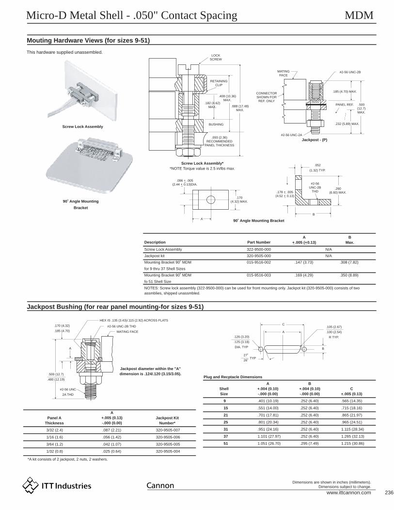
NOTES: Screw lock assembly (322-9500-000) can be used for front mounting only. Jackpot kit (320-9505-000) consists of twoassmblies, shipped unassmbled.
322-9500-000
320-9505-000
015-9516-002
015-9516-003
.147 (3.73)
.169 (4.29)
.308 (7.82)
.350 (8.89)
N/A
N/A
Part Number
3/32 (2.4)
1/16 (1.6)
3/64 (1.2)
1/32 (0.8)
*A kit consists of 2 jackpost, 2 nuts, 2 washers.
.087 (2.21)
.056 (1.42)
.042 (1.07)
.025 (0.64)
320-9505-007
320-9505-006
320-9505-005
320-9505-004
Panel AThickness
Jackpost KitNumber*
9
15
21
25
31
37
51
.401 (10.19)
.551 (14.00)
.701 (17.81)
.801 (20.34)
.951 (24.16)
1.101 (27.97)
1.051 (26.70)
.252 (6.40)
.252 (6.40)
.252 (6.40)
.252 (6.40)
.252 (6.40)
.252 (6.40)
.295 (7.49)
.565 (14.35)
.715 (18.16)
.865 (21.97)
.965 (24.51)
1.115 (28.34)
1.265 (32.13)
1.215 (30.86)
ShellSize
Plug and Recptacle Dimensions
Jackpost diameter within the "A"dimension is .124/.120 (3.15/3.05).
HEX IS .135 (3.43)/.115 (2.92) ACROSS FLATS
#2-56 UNC-2B THD
MATING FACE
.170 (4.32)
.185 (4.70)
A
.500 (12.7)
.480 (12.19)
#2-56 UNC
2A THD
.126 (3.20)
.125 (3.18)
DIA. TYP
.105 (2.67)
.100 (2.54)
R TYP.
.052
(1.32) TYP.
.260(6.60) MAX.
#2-56UNC-2B
THD
B
.178 +_ .005(4.52 +_ 0.13)
.096 +_ .005(2.44 +_ 0.13)DIA.
.093 (2.36)RECOMMENDED
PANEL THICKNESS
BUSHING
.182 (4.62)MAX. .688 (17.48)
MAX.
.408 (10.36)MAX.
RETAININGCLIP
LOCKSCREW
MATINGFACE
CONNECTORSHOWN FOR
REF. ONLY
#2-56 UNC-2B
.185 (4.70) MAX.
.500(12.7)MAX.
PANEL REF.
.232 (5.89) MAX.
#2-56 UNC-2A
.170(4.32) MAX.
A
27˚
26˚TYP
A
C
B
A+.004 (0.10)-.000 (0.00)
B+.004 (0.10)-.000 (0.00)
C+_.005 (0.13)
A+_.005 (+_0.13)
A+.005 (0.13)-.000 (0.00)
BMax.
www.ittcannon.com 237
Dimensions are shown in inches (millimeters).Dimensions subject to change.
Micro-D Metal Shell - .050" Contact Spacing MDM
Mounting Hardware Views (sizes 9-51)
Mounting Hardware to Military Specification (for sizes 9 - 100) per MIL-C-83513/5
This hardware is factory installed.
.014 +_ .004(0.36 +_ 0.10) ALLOWABLE
DIAMETRAL FLOAT�.020 (0.51) MAX. ALLOWABLE
AXIAL FLOAT
.150 +_ .003
(3.81 +_ .076)
.185 (4.70)MAX .093
(2.36)REF.
.090 +_ .0015
(2.29 +_ 0.038)DIA .031 +_ .003
(0.79 +_ 0.08)
MATINGFACE
MATINGFACE
#2-56UNC-2A
.490(12.45) MAX
.735 (18.67)MAX.
MATING�FACE
CONNECTOR�SHOWN FOR�REF ONLY
HEX HEAD - .050 (1.27) ACROSS FLATS.050 (1.27) DEEP (REF)
.155(3.94) MAX.
PART HAS A .040 (1.02)MAX. AXIAL FLOAT#2-56UNC-2A
Jackscrew - (L) Low ProfileJackscrew - (K) StandardFloat Mount - (F)
Shown here is a cutaway view of the float mount for the MD connector. The basic shell dimensions are the same for the float mount and the screwmounting hole configurations. Veiw shown is for standard float mount front panel mounting. Reverse mounting is available on request.
* NOTE: Torque vales are as follows: Low Profile Jackscrew (L)-2.5 in/lbs Standard Jackscrew (K)-2.5 in/lbs
Repair kit available-consult factory.
This hardware supplied in kits unassembled (2 pieces of each item).
To order hardware kits separately, order either by M83513/5-** or by 320-950X-XXX.
Description
Slotted Head Jackscrew Assy Low Profile (Figure 1) M5 320-9508-025
M6 320-9508-027
M2 320-9508-026
M3 320-9508-028
M7 320-9505-033
05
06
02
03
07
M15 320-9508-021
M16 320-9508-023
M12 320-9508-022
M13 320-9508-024
M17 320-9505-030
*Size 100 requires B1 size mounting holes.
15
16
12
13
17
Slotted Head Jackscrew Assy Low Profile (Figure 2)
Allen Head Jackscrew Assy Low Profile (Figure 1)
Allen Head Jackscrew Assy High Profile (Figure 2)
Jackpost Assy (Figure 3)
Size 9-51Mod Code Part Number
Size 100*Mod Code Part Number* * * *
#2-56 UNC-2ATHREAD TYP.
PLUG (REF. WITH.092 (2.34) DIA.MOUNTING HOLES
POTTING WELL (REF.)
.361 (9.17) MAX.
.390 (9.91) MAX.SIZE 100 ONLY
.010 (0.25)TH'K (REF.)
.125 (3.18) HEX.
.187 (4.75) HEX.
#2-56 UNC-2B THREAD#4-40 UNC -2A THREAD
LOCKWASHER
RETAINING NUT.154 (3.91) HEX..187 (4.75) HEX.
.062 +_ .010(.157 +_ 0.25)
SIZE 100 SAME
.475 +_ .025(12.06 +_ 0.64)
SIZE 100 SAME
.190/.185(4.83/4.70)
.185/.175(4.70/4.44)
.062 (1.57)HEX. (REF.)
.868 (22.05) MAX.
.902 (22.91) MAX.
.010 (0.25)TH'K (REF.)
#2-56 UNC-2ATHREAD TYP.
PLUG (REF.) WITH.092 (2.34) DIA.MOUNTING HOLES
POTTING WELL(REF.)
Figure 1. Jackscrew - Low profileSlotted Head
Size 9-51Size 100*
Figure 3. Jackpost AssemblySize 9-51Size 100*
Allen headOptional Head Configuration
Plug and ReceptacleLow and High Profile
Size 9-51Size 100* (same dimensions)
Figure 2. Jackscrew - High ProfileSlotted Head
Size 9-51Size 100*
PART HAS A .040 (1.02)MAX AXIAL FLOAT
CONNECTORSHOWN FORREF. ONLY
MATING�FACE
#4-40UNC-2A
.735 (18.64)MAX.
Jackscrew - (K) Standard
PART HAS A .040 (1.02)MAX AXIAL FLOAT
CONNECTOR�SHOWN FOR�REF. ONLY
www.ittcannon.com 238
Dimensions are shown in inches (millimeters).Dimensions subject to change.
Micro-D Metal Shell - .050" Contact Spacing MDM
Mounting Hardware Views (for size 100)
Jackpost Bushing (for Rear Panel Mounting)
This hardware supplied unassembled.
This hardware is factory installed.
.014 +_ .004
(0.36 +_ 0.10) ALLOWABLE
DIAMETRAL FLOAT�
.020 (0.51) MAX. ALLOWABLE
AXIAL FLOAT
.174 +_ .005
(4.4 +_ .10)
.185 (4.70)MAX .093
(2.36)REF.
.116 +_ .002(2.29 +_ .051)
DIA.031 +_ .003
(0.79 +_ 0.08)
ENGAGING FACE
RECEPTACLE SHOWNFOR REF. ONLY
#4-40 THREADRETAINING NUT
.500 (12.70)MAX.
.185 (4.70)
.170 (4.32)A
#4-40 UNC-2B
3/16" HEX.LOCKING POST 3/16" HEX.
LOCKING POST
.125
(3.18
1.516
(38.51
.401
(10.18
1.800 +_ .005(45.72 +_ 0.13)
.161 (4.09)
.159 (4.04)DIA.
R
MATING�FACE
Float Mount - (F) Std.
#4-40 UNC-2A
#4-40 UNC-2B INNER THD
.184 (4.70)MAX.
.500 (12.70)MAX.
PANEL - MAY BE USED WITH.093 (2.36) MAXTHICK PANEL
.123 +_ .005(3.12 +_ 0.13) DIA.
$4-40 UNC-2BTHD
A
.395 (10.03)MAX.
.235 +_ .005(5.97 +_ 0.13)
HEX. SOCKET HD..078 (1.98) ACROSS FLATS
.050 (1.27 MIN. DEPTH
.155 (3.94) MAX.
.040 (1.02) MAX.AXIAL FLOAT
#4-40 UNC-2AMATING SIDE
*NOTE: Torque vales are as follows: Low Profile Jackscrew (L)-4.0 in/lbs
Standard Jackscrew (K)-4.0 in/lbs
.064 +_ .010(1.62 +_ 0.25) TYP.
B
180(4.57 )
+.010-.005
+.025-0.13
)
+.004-.000
+1.10-0.00
)
+.004-.000
+1.10-0.00
)
+.005-.000
+0.13-0.00
Jackpost - (P)90˚Angle MountingBracket
90˚ Angle MountingBracket
Description
Jackpost kit
Mounting Bracket 90˚ MDM
PanelThickness
Jackpost KitNumber*
Dimensions for Rear Panel Mounting
A+.005 (0.13)-.000 (0.00)
3/32 (2.4)
1/16 (1.6)
1/32 (0.8)
3/64 (1.2)
*2 jackposts, 2 nuts, 2 washers
.087 (2.21)
.058 (1.42)
.025 (0.64)
.042 (1.07)
320-9505-013
320-9505-012
320-9505-010
320-9505-011
320-9505-015
015-9528-000 .191 (4.85) .370 (9.40)
N/A
Part NumberA
+_ .005 (0.13)B
Max.
#4 LOCK WASHER
MATING SIDE
Jackscrew - (L) (Low Profile)
www.ittcannon.com 239
Dimensions are shown in inches (millimeters).Dimensions subject to change.
Micro-D Metal Shell - .050" Contact Spacing MDM
Connector Saver
.040 (1.02) MAX. ALLOWABLEAXIAL FLOAT BUSHING-JACKSCREW/JACKPOST
HARDWARE(OPTIONAL, FOR REFERENCE ONLY.MUST BE SPECIFIED BY CUSTOMER.)
SOCKET
CONN. RECEPT.
INTERFACIAL SEAL
.185 (4.70) MAX. (TYP.)
E RING (TYP.)
CONN., PLUG
BACKPOTTING, EPOXY
.790 (20.07) MAX.
.315(8.00)MAX.
.090 (2.29) REF.(TYP.)
.900 (22.86) REF.
MDM Size 9 Shown
Size
9
15
21
25
31
37
51
100
MDM98479-86
MDM98479-87
MDM98479-88
MDM98479-89
MDM98479-90
MDM98479-91
MDM98479-92
MDM98479-93
MDM98479-18
MDM98479-19
MDM98479-20
MDM98479-21
MDM98479-14
MDM98479-15
MDM98479-16
MDM98479-17
MDM98479-78
MDM98479-79
MDM98479-80
MDM98479-81
MDM98479-82
MDM98479-83
MDM98479-84
MDM98479-85
MDM-97294-371
MDM-97294-372
MDM-97294-373
MDM-97294-374
MDM-97294-375
MDM-97294-376
MDM-97294-377
MDM-97294-717
320-9505-014**
320-9505-014**
320-9505-014**
320-9505-014**
320-9505-014**
320-9505-014**
320-9505-014**
320-9508-014***
.785 (19.94)
.935 (23.75)
1.085 (27.56)
1.185 (30.10)
1.335 (33.91)
1.485 (37.72)
1.435 (36.45)
2.170 (55.12)
Kit contains 2 bushings-jackpost/jackscrew and 2 E rings.Size 9-51-#2-56 UNC2B ThreadSize 100-#4-40 UNC2B Thread
***
***
.565 (14.35)
.715 (18.16)
.865 (21.97)
.965 (24.51)
1.115 (28.32)
1.265 (32.13)
1.215 (30.86)
1.800 (45.72)
.308 (7.82)
.308 (7.82)
.308 (7.82)
.308 (7.82)
.308 (7.82)
.308 (7.82)
.351 (8.91)
.394 (10.01)
With HardwareA174 Electroless Nickel Cadmium Plated
W/O Hardware With Hardware W/O Hardware *Hadware KitsA
Max.B
+_ .005 (0.13)C
Max.
#2-56 UNC-2A(TYP.)
PIN
C
B A
Save wear and tear on your equipment and systems
connectors by using the "Connector Saver".
Simply mate the "Connectors Saver" to your unit and
use the opposite side for your testing interface...
less wear, less tear, less chansce of damage. It is
available in all seven standard MDM layouts. Mat-
ing hardware is available and can be ordered either
separately or included with the connector saver.
The multi-matings and unmatings experienced by
most connectors during testing and final check out
can be eliminated.
www.ittcannon.com 240
Dimensions are shown in inches (millimeters).Dimensions subject to change.
Micro-D Metal Shell - .050" Contact Spacing MIL-C-83513
How to Order - ITT Cannon Part Number Nomenclature to MIL-C-83513
ITT CANNON SERIESMetal Shell, Liquid Crystal Polymer (LCP)Diallyl Phthalate InsulatorPolyester Insulator
MDMMDBMDVB
---
Plug, Connector, SolderpotReceptacle, Connector, SolderpotPlug, Connector, Crimp TypeReceptacle, Connector, Crimp TypeHardware Only
Metal Shell
Plastic
0102030405
-----
Plug, Connector, SolderpotReceptacle, Connector, SolderpotPlug, Connector, Crimp TypeReceptacle, Connector, Crimp Type
06070809
----
long, #26 AWG per MIL-W-22759/11-26-9long, #26 AWG per MIL-W-22759/11-26-9long, #26 AWG per MIL-W-22759/11-26Color Coded per MIL-STD-681, System 1long, #26 AWG per MIL-W-22759/11-26-Color Coded per MIL-STD-681, System 1long. #25 AWG, type S per QQ-W-343,Gold Platedlong, #25 AWG, type S per QQ-W-343,Gold Platedlong, #25 AWG, type S per QQ-W-W-343,Tin Platedlong, #25 AWG, type S per QQ-W-343,Tin Platedlong, #26 AWG per MIL-W-22759/33-26-9long, #26 AWG per MIL-W-22759/33-26-9long, #26 AWG per MIL-W-22759/33-26Color Coded per MIL-STD-681, System 1long, #26 AWG per MIL-W-22759/33-26Color Coded per MIL-STD-681, System 1long, #26 AWG per MIL-W-22759/11-26-9long, #26 AWG per MIL-W-22759/11-26Color Coded per MIL-STD-681, System 1long, #26 AWG per MIL-W-22759/33-26-9long, #26 AWG per MIL-W-22759/33-26Color Coded per MIL-STD-681, System 1
18"36"18"
36"
.5"
1.0"
.5"
1.0"
18"36"18"
36"
72"72"
72"72"
010203
04
05
06
07
08
091011
12
1314
1516
---
-
-
-
-
-
---
-
--
--
9 Contact15 Contact21 Contact25 Contact31 Contact37 Contact51 Contact
100 Contact
METAL SHELL
No Number - For Solderpot
(Specify when ordering, if necessary.)
For every Mil-Spec P/N, ITT has one corresponding part numbers.Example: ITT P/N's MDM01-A9
-
-
-
-
-
-
-
For space application, connector shell finish must be "A174"and wire must be per MIL-W-22759/33-26.
Any deviations to these P/N's will result in assignment of a specialP/N, consult factory.
No size 100 in plastic type connector.
Color coding in accordance with MIL-STD-681, System 1 except theappropriate color code is the individual contact cavity number minus1 for contact positions.
For mounting hardware to Military Specification (sizes 9 to 100) seepage 238.
No number - for plastic type connectorNo number - for CadmiumA174 - Electroless Nickel
Tolerance on wire lengths-18", 36" and 72" long, +1.00"/-0.00" .5" and 1.00" + .200"/-.000"
PLASTIC
9 Contact15 Contact21 Contact25 Contact31 Contact37 Contact51 Contact
A9B15C21D25E31F37G51H100
--------
MD** 01 * * * * * *H100- -
MIL-C-83513 SLASH SHEET
INSERT ARRANGEMENT
WIRE TYPE
SHELL FINISH
Qualification to slash sheets 10 thru 27 for the PCB connector will be announeced when completed.
NOTES:
}
}
1
7
5
5
6
6
3
3
3 6
37
6
5
4
2
3
1
3 6
6
3
3 6
www.ittcannon.com 241
Dimensions are shown in inches (millimeters).Dimensions subject to change.
Micro-D Metal Shell - .050" Contact Spacing MIL-C-83513
How to Order - MIL-C-83513 Part Number Nomenclature
SERIESConnector, Electrical, RectangularMicrominiature, Polarized Shell
Plug, Connector, SolderpotReceptacle, Connector, SolderpotPlug, Connector, Crimp TypeReceptacle, Connector, Crimp TypeHardware Only
Metal Shell
Plastic
0102030405
-----
Plug, Connector, SolderpotReceptacle, Connector, SolderpotPlug, Connector, Crimp TypeReceptacle, Connector, Crimp Type
06070809
----
long, #26 AWG per MIL-W-22759/11-26-9long, #26 AWG per MIL-W-22759/11-26-9long, #26 AWG per MIL-W-22759/11-26Color Coded per MIL-STD-681, System 1long, #26 AWG per MIL-W-22759/11-26-Color Coded per MIL-STD-681, System 1long. #25 AWG, type S per QQ-W-343,Gold Platedlong, #25 AWG, type S per QQ-W-343,Gold Platedlong, #25 AWG, type S per QQ-W-W-343,Tin Platedlong, #25 AWG, type S per QQ-W-343,Tin Platedlong, #26 AWG per MIL-W-22759/33-26-9long, #26 AWG per MIL-W-22759/33-26-9long, #26 AWG per MIL-W-22759/33-26Color Coded per MIL-STD-681, System 1long, #26 AWG per MIL-W-22759/33-26Color Coded per MIL-STD-681, System 1long, #26 AWG per MIL-W-22759/11-26-9long, #26 AWG per MIL-W-22759/11-26Color Coded per MIL-STD-681, System 1long, #26 AWG per MIL-W-22759/33-26-9long, #26 AWG per MIL-W-22759/33-26Color Coded per MIL-STD-681, System 1
18"36"18"
36"
.5"
1.0"
.5"
1.0"
18"36"18"
36"
72"72"
72"72"
010203
04
05
06
07
08
091011
12
1314
1516
---
-
-
-
-
-
---
-
--
--
9 Contact15 Contact21 Contact25 Contact31 Contact37 Contact51 Contact
100 Contact
METAL SHELL
No Number - For Solderpot
(Specify when ordering, if necessary.)
For every Mil-Spec P/N, ITT has one corresponding part numbers.Example: ITT P/N's MDM01-A9
-
-
-
-
-
-
-
For space application, connector shell finish must be "N" andwire must be per MIL-W-22759/33-26.
Any deviations to these P/N's will result in assignment of a specialP/N, consult factory.
No size 100 in plastic type connector.
Color coding in accordance with MIL-STD-681, System 1 except theappropriate color code is the individual contact cavity number minus1 for contact positions.
For mounting hardware to Military Specification (sizes 9 to 100) seepage 238.
No letter - for plastic type connectorC - CadmiumN - Electroless Nickel
Tolerance on wire lengths-18", 36" and 72" long, +1.00"/-0.00" .5" and 1.00" + .200"/-.000"
PLASTIC
9 Contact15 Contact21 Contact25 Contact31 Contact37 Contact51 Contact
ABCDEFGH
--------
M83513/ 01 * * CA- -
MIL-C-83513 SLASH SHEET
INSERT ARRANGEMENT
WIRE TYPE
SHELL FINISH
Qualification to slash sheets 10 thru 27 for the PCB connectors will be announced when completed.
NOTES:
}
}
1
7
5
5
6
6
3
3
3 6
37
6
5
4
2
3
1
3 6
6
3
3 6
www.ittcannon.com 242
Dimensions are shown in inches (millimeters).Dimensions subject to change.
Micro-D PCB - .050" Contact Spacing MDM-PCB
How to Order - MDM-PCB Series
SERIES
INSULATOR MATERIAL
CONTACT ARRANGEMENT
CONTACT TYPE
TERMINATION TYPE
MOUNTING HARDWARE (Shell Flange)
MOUNTING HARDWARE FOR PCB
TERMINATION TAIL LENGTH MODIFICATION CODE
SHELL FINISH MODIFICATION CODES
SERIES MOUNTING HARDWARE FOR PCB
TERMINATION TAIL LENGTH MODIFICATION CODE
SHELL FINISH MODIFICATION CODES
INSULATOR MATERIAL
CONTACT ARRANGEMENT
CONTACT TYPE
TERMINATION TYPE
MOUNTING HARDWARE (Shell Flange)
MDM - Microm "D" Metal Shell T - Threaded Insert #2-56 Thd for Shell Sizes 9 thru 51 #4-40 Thd for Shell Size 100No letter - none
None - .109 (2.77) +_.015 (0.38) StandardL61 - .125 (3.18)L56 - .150 (3.81)L57 - .190 (4.83)L39 - .250 (6.35)L58 - .375 (9.52)
None - Yellow Chromate/Cadmium over NickelA174 - Electroless NickelA172 - Gold over NickelA141 - Irridite/AlodineA30 - Black Anodize
(For special modification codes, consult factory.)
NOTE: Back molding material - Epoxy Hysol #MG40FS
MDM * - -25 P PBS T L39 A174
Liquid Crystal Polymer (LCP)
9, 15, 21, 25, 31, 37, 51, and 100Size 100 not available in "BR"
P - Pin (Plug)S - Socket (Receptacle)
BS - Straight PCB TerminationBR - 90û PCB TerminationCBR - 90û Narrow Profile PCB Terminations
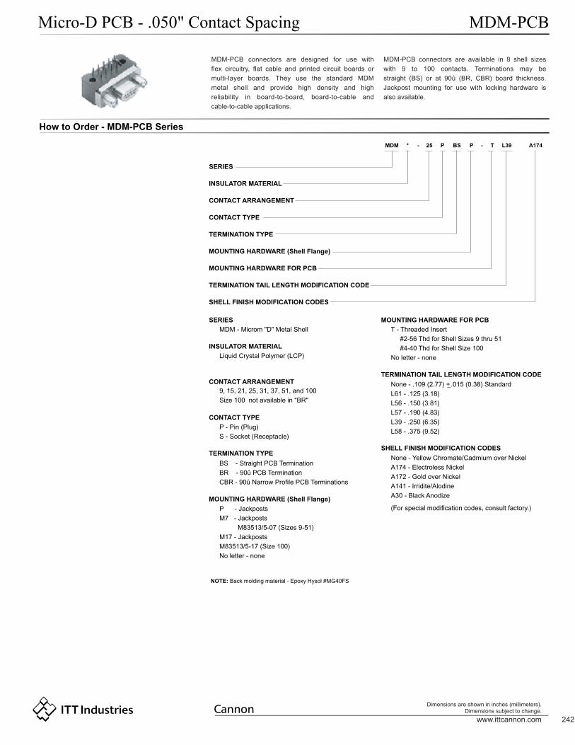
P - JackpostsM7 - Jackposts M83513/5-07 (Sizes 9-51)M17 - JackpostsM83513/5-17 (Size 100)No letter - none
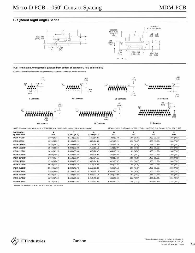
MDM-PCB connectors are designed for use withflex circuitry, flat cable and printed circuit boards ormulti-layer boards. They use the standard MDMmetal shell and provide high density and highreliability in board-to-board, board-to-cable andcable-to-cable applications.
MDM-PCB connectors are available in 8 shell sizeswith 9 to 100 contacts. Terminations may bestraight (BS) or at 90û (BR, CBR) board thickness.Jackpost mounting for use with locking hardware isalso available.
*
www.ittcannon.com 243
Dimensions are shown in inches (millimeters).Dimensions subject to change.
Micro-D PCB - .050" Contact Spacing MDM-PCB
BS (Board Straight) Series
.096 +_ .005(2.44 +_ 0.13) DIA.
Size 9-51)
.120 +_ .005(3.05 +_ 0.13)
Size 100
CAV.#1 LAST
CAV.
G
JACKPOST (9-51)#2-56 UNC-2B TYP.
JACKPOST (100)#4-40 UNC-2B TYP.
.186 (4.72) MAX. PLUG
.198 (5.03) MAX. RECEPTACLE
.109 +_ 0.15(2.77 +_ 0.38)
D
E
HJ
K
LAST CAV.
CAV. #1
.050(1.27)
6 7 8 9
1 2 3 4 5
9 10 11 12 13 14 15
1 2 3 4 5 6 7 8
12 13 14 15 16 17 18 19 20 21
1 2 3 4 5 6 7 8 9 10 11
14 15 16 17 18 19 20 21 22 23 24 25
1 2 3 4 5 6 7 8 9 10 11 12 13
17 18 19 20 21 22 23 24 25 26 27 28 29 30 31
1 2 3 4 5 6 7 8 9 10 11 12 13 14 15 16
20 21 22 23 24 25 26 27 28 29 30 31 32 33 34 35 36 37
1 2 3 4 5 6 7 8 9 10 11 12 13 14 15 16 17 18 19
36 37 38 39 40 41 42 43 44 45 46 47 48 49 50 51
19 35
1 2 3 4 5 6 7 8 9 10 11 12 13 14 15 16 17 18
1 2 3 4 5 6 7 8 9 10 11 12 13 14 15 16 17 18 19 20 21 22 23 24 25 26
76 77 78 75 80 81 82 83 84 85 86 87 88 89 90 91 92 93 94 95 96 97 98 99 100
52 53 54 55 56 57 58 59 60 61 62 63 64 65 66 67 68 69 70 71 72 73 74 75
27 28 29 30 31 32 33 34 35 36 37 38 39 40 41 42 43 44 45 46 47 48 49 50 51
.050(1.27) .050
(1.27).100
(2.54)TYP.
.150(3.81)
.150(3.81)
.150(3.81)
.150(3.81)
.150(3.81)
.050(1.27)
.050(1.27)
.050(1.27)
.150(3.81).375
(9.53).225
(5.72)TYP.
.225(5.72)
PCB Termination Arrangements* (Viewed from PCB solder side)
9 Contacts
31 Contacts
15 Contacts
37 Contacts
100 Contacts
51 Contacts
21 Contacts 25 Contacts
Identification number shown for plug connector, use reverse order for socket connector.
NOTE: Standard lead termination is #24 AWG, solid copper, solder or tin dipped
All Termination Configurations .100 (2.54) x .100 (2.54) Grid Pattern, Offset .050 (1.27)
*For jackpost, add letter "P" or "M7" for sizes 9-51, "M17" for size 100.
Part NumberBy Shell Size
AMax.
B+_.007 (.018)
C+_.005 (.013)
DMax.
EMax.
FMax.
GMax.
HMax.
JMax.
KMax.
MDM-9PBS*
MDM-9SBS*
MDM-15PBS*
MDM-15SBS*
MDM-21PBS*
MDM-21SBS*
MDM-25PBS
MDM-25SBS*
MDM-31PBS*
MDM-31SBS*
MDM-37PBS*
MDM-37SBS*
MDM-51PBS*
MDM-51SBS*
MDM-100PBS*
MDM-100SBS*
1.390 (35.31)
1.390 (35.31)
1.390 (35.31)
1.390 (35.31)
1.690 (43.93)
1.690 (43.93)
1.740 (44.20)
1.740 (44.20)
2.040 (51.82)
2.040 (51.82)
2.340 (59.44)
2.340 (59.44)
2.270 (67.66)
2.270 (67.66)
3.070 (77.98)
3.070 (77.98)
1.150 (29.21)
1.150 (29.21)
1.150 (29.21)
1.150 (29.21)
1.450 (36.83)
1.450 (36.83)
1.500 (38.10)
1.500 (38.10)
1.800 (45.72)
1.800 (45.72)
2.100 (53.34)
2.100 (53.34)
2.000 (50.80)
2.000 (50.80)
2.800 (71.12)
2.800 (71.12)
.565 (14.35)
.565 (14.35)
.715 (18.16)
.715 (18.16)
.865 (21.97)
.865 (21.97)
.965 (24.51)
.965 (24.51)
1.115 (28.32)
1.115 (28.32)
1.265 (32.13)
1.265 (32.13)
1.215 (30.86)
1.215 (30.86)
1.800 (45.72)
1.800 (45.72)
.785 (19.94)
.785 (19.94)
.935 (23.75)
.935 (23.75)
1.085 (27.56)
1.085 (27.56)
1.185 (30.10)
1.185 (30.10)
1.335 (33.91)
1.335 (33.91)
1.485 (37.72)
1.485 (37.72)
1.435 (36.45)
1.435 (36.45)
2.175 (55.24)
2.175 (55.24)
.334 (8.48)
.402 (10.21)
.484 (12.29)
.552 (13.97)
.634 (16.10)
.702 (17.83)
.734 (18.64)
.802 (20.37)
.884 (22.45)
.952 (24.18)
1.034 (26.26)
1.102 (27.99)
.984 (24.99)
1.052 (26.72)
1.384 (35.15)
1.508 (38.30)
.185 (4.70)
.253 (6.43)
.185 (4.70)
.253 (6.43)
.185 (4.70)
.253 (6.43)
.185 (4.70)
.253 (6.43)
.185 (4.70)
.253 (6.43)
.185 (4.70)
.253 (6.43)
.228 (5.79)
.296 (7.52)
.271 (6.88)
.394 (10.01)
.308 (7.82)
.308 (7.82)
.308 (7.82)
.308 (7.82)
.308 (7.82)
.308 (7.82)
.308 (7.82)
.308 (7.82)
.308 (7.82)
.308 (7.82)
.308 (7.82)
.308 (7.82)
.351 (8.92)
.351 (8.92)
.460 (11.68)
.460 (11.68)
.165 (4.19)
.165 (4.19)
.165 (4.19)
.165 (4.19)
.165 (4.19)
.165 (4.19)
.165 (4.19)
.165 (4.19)
.165 (4.19)
.165 (4.19)
.165 (4.19)
.165 (4.19)
.165 (4.19)
.165 (4.19)
.303 (7.70)
.303 (7.70)
.355 (9.02)
.355 (9.02)
.355 (9.02)
.355 (9.02)
.355 (9.02)
.355 (9.02)
.355 (9.02)
.355 (9.02)
.355 (9.02)
.355 (9.02)
.355 (9.02)
.355 (9.02)
.355 (9.02)
.355 (9.02)
.550 (12.70)
.550 (12.70)
.555 (14.10)
.555 (14.10)
.555 (14.10)
.555 (14.10)
.555 (14.10)
.555 (14.10)
.555 (14.10)
.555 (14.10)
.555 (14.10)
.555 (14.10)
.555 (14.10)
.555 (14.10)
.555 (14.10)
.555 (14.10)
.686 (17.42)
.686 (17.75)
NOTE: Dimensions shown are for reference only-consult factory for final design dimensions.
.100 (2.54)REF.
F
A
B
C
.300(7.62)
www.ittcannon.com 244
Dimensions are shown in inches (millimeters).Dimensions subject to change.
Micro-D PCB - .050" Contact Spacing MDM-PCB
BR (Board Right Angle) Series
PCB Termination Arrangements (Viewed from bottom of connector, PCB solder side.)
Identification number shown for plug connector, use reverse order for socket connector.
.109 +_ .015(2.77 +_ 0.38)
A
C
E G
.186 (4.72)MAX. PLUG.198 (5.05)
MAX.
.100(2.54)TYP.
B
D
JACKPOST�#2-56 UNC-2B TYP.
.125 +_ .015(3.18 +_ 0.38)
F
.150 +_ .010(3.8 +_ 0.25)
.096 +_ .005(2.44 +_ 0.31)
.050(1.27)TYP.
.100 TYP.
CAV.#1
LASTCAV.
NOTE: Standard lead termination is #24 AWG, gold plated, solid copper, solder or tin dripped.
*For jackpost, add letter "P" or "M7" for sizes 9-51, "M17" for size 100.
Part NumberBy Shell Size
MDM-9PBR*
MDM-9SBR*
MDM-15PBR*
MDM-15SBR*
MDM-21PBR*
MDM-21SBR*
MDM-25PBR*
MDM-25SBR*
MDM-31PBR*
MDM-31SBR*
MDM-37PBR*
MDM-37SBR*
MDM-51PBR*
MDM-51SBR*
1.390 (35.31)
1.390 (35.31)
1.540 (39.12)
1.540 (39.12)
1.690 (42.93)
1.690 (42.93)
1.790 (45.47)
1.790 (45.47)
2.040 (51.82)
2.040 (51.52)
2.340 (59.44)
2.340 (59.44)
1.875 (47.63)
1.875 (47.63)
1.150 (29.21)
1.150 (29.21)
1.300 (33.02)
1.300 (33.02)
1.450 (36.83)
1.450 (36.83)
1.550 (39.37)
1.550 (39.37)
1.800 (45.72)
1.800 (45.72)
2.100 (53.34)
2.100 (53.34)
1.600 (40.64)
1.600 (40.64)
.565 (14.35)
.565 (14.35)
.715 (18.16)
.715 (18.16)
.865 (21.97)
.865 (21.97)
.965 (24.51)
.965 (24.51)
1.115 (28.32)
1.115 (28.32)
1.265 (32.13)
1.265 (32.13)
1.215 (30.86)
1.215 (30.86)
.334 (8.48)
.402 (10.21)
.484 (12.29)
.552 (13.97)
.634 (16.10)
.702 (17.83)
.734 (18.64)
.802 (20.37)
.884 (22.45)
.952 (24.18)
1.034 (26.26)
1.102 (27.99)
.984 (24.99)
1.052 (26.72)
.185 (4.70)
.253 (6.43)
.185 (4.70)
.253 (6.43)
.185 (4.70)
.253 (6.43)
.185 (4.70)
.253 (6.43)
.185 (4.70)
.253 (6.43)
.185 (4.70)
.253 (6.43)
.228 (5.79)
.296 (7.52)
.455 (11.56)
.455 (11.56)
.455 (11.56)
.455 (11.56)
.455 (11.56)
.455 (11.56)
.455 (11.56)
.455 (11.56)
.455 (11.56)
.455 (11.56)
.455 (11.56)
.455 (11.56)
.565 (14.35)
.565 (14.35)
.308 (7.82)
.308 (7.82)
.308 (7.82)
.308 (7.82)
.308 (7.82)
.308 (7.82)
.308 (7.82)
.308 (7.82)
.308 (7.82)
.308 (7.82)
.308 (7.82)
.308 (7.82)
.351 (8.92)
.351 (8.92)
AMax.
B+_ .007 (.018)
C+_ .005 (.013)
DMax.
EMax.
FMax.
GMax.
All Termination Configurations .100 (2.54) x .100 (2.54) Grid Pattern, Offset .050 (1.27).
6 7 8 9
1 2 3 4 5
9 10 11 12 13 14 15
1 2 3 4 5 6 7 8
12 13 14 15 16 17 18 19 20 21
1 2 3 4 5 6 7 8 9 10 11
14 15 16 17 18 19 20 21 22 23 24 25
1 2 3 4 5 6 7 8 9 10 11 12 13
17 18 19 20 21 22 23 24 25 26 27 28 29 30 31
1 2 3 4 5 6 7 8 9 10 11 12 13 14 15 16
20 21 22 23 24 25 26 27 28 29 30 31 32 33 34 35 36 37
1 2 3 4 5 6 7 8 9 10 11 12 13 14 15 16 17 18 19
36 37 38 39 40 41 42 43 44 45 46 47 48 49 50 51
19 20 21 22 23 24 25 26 27 28 29 30 31 32 33 34 35
1 2 3 4 5 6 7 8 9 10 11 12 13 14 15 16 17 18.150
(3.81)
.050(1.27).150
(3.81)
.150(3.81)
.150(3.81)
.150(3.81)
.150(3.81)
.175(4.45)
.150(3.81)
.375(9.53)
.150(3.81)
.150(3.81)
.225(5.72)
9 Contacts
31 Contacts
15 Contacts
37 Contacts 51 Contacts
21 Contacts 25 Contacts
+ +
www.ittcannon.com 245
Dimensions are shown in inches (millimeters).Dimensions subject to change.
Micro-D PCB - .050" Contact Spacing MDM-PCB
CBR (Condensed Board Right Angle) Series
PCB Termination Arrangements (Viewed from bottom of connector, PCB solder side.)
Identification number shown for plug connector, use reverse order for socket connector.
NOTE: Standard lead termination is #24 AWG, solid copper, solder or tin dripped.
*For jackpost, add letter "P" or "M7" for sizes 9-51, "M17" for size 100.
Part NumberBy Shell Size
MDM-9PCBR*
MDM-9SCBR*
MDM-15PCBR*
MDM-15SCBR*
MDM-21PCBR*
MDM-21SCBR*
MDM-25PCBR*
MDM-25SCBR*
MDM-31PCBR*
MDM-31SCBR*
MDM-37PCBR*
MDM-37SCBR*
MDM-51PCBR*
MDM-51SCBR*
MDM-100PCBR*
MDM-100SCBR*
.785 (19.94)
.785 (19.94)
.935 (23.75)
.935 (23.75)
1.085 (27.56)
1.085 (27.56)
1.185 (30.10)
1.185 (30.10)
1.335 (33.91)
1.335 (33.91)
1.485 (37.72)
1.485 (37.72)
1.435 (36.45)
1.435 (36.45)
2.170 (55.12)
2.170 (55.12)
.565 (14.35)
.565 (14.35)
.715 (18.16)
.715 (18.16)
.865 (21.97)
.865 (21.97)
.965 (24.51)
.965 (24.51)
1.115 (28.32)
1.115 (28.32)
1.265 (32.13)
1.265 (32.13)
1.215 (30.86)
1.215 (30.86)
1.800 (45.72)
1.800 (45.72)
.334 (8.48)
.402 (10.21)
.484 (12.29)
.552 (13.97)
.634 (16.10)
.702 (17.83)
.734 (18.64)
.802 (20.37)
.884 (22.45)
.952 (24.18)
1.034 (26.26)
1.102 (27.99)
.984 (24.99)
1.052 (26.72)
1.384 (35.15)
1.508 (38.10)
.308 (7.82)
.308 (7.82)
.308 (7.82)
.308 (7.82)
.308 (7.82)
.308 (7.82)
.308 (7.82)
.308 (7.82)
.308 (7.82)
.308 (7.82)
.308 (7.82)
.308 (7.82)
.351 (8.92)
.351 (8.92)
.394 (10.01)
.394 (10.01)
.185 (4.70)
.253 (6.43)
.185 (4.70)
.253 (6.43)
.185 (4.70)
.253 (6.43)
.184 (4.70)
.253 (6.43)
.185 (4.70)
.253 (6.43)
.185 (4.70)
.253 (6.43)
.228 (5.79)
.296 (7.52)
.271 (6.88)
.394 (10.01)
.420 (10.67)
.420 (10.67)
.420 (10.67)
.420 (10.67)
.420 (10.67)
.420 (10.67)
.420 (10.67)
.420 (10.67)
.520 (13.21)
.520 (13.21)
.520 (13.21)
.520 (13.21)
.650 (16.15)
.650 (16.15)
1.000 (25.40)
1.000 (25.40)
.250 (6.35)
.250 (6.35)
.250 (6.35)
.250 (6.35)
.250 (6.35)
.250 (6.35)
.250 (6.35)
.250 (6.35)
.250 (6.35)
.250 (6.35)
.250 (6.35)
.250 (6.35)
.300 (7.62)
.300 (7.62)
.400 (10.16)
.400 (10.16)
.230 (5.81)
.230 (5.81)
.130 (3.30)
.130 (3.30)
.130 (3.30)
.130 (3.30)
.130 (3.30)
.130 (3.30)
.130 (3.30)
.130 (3.30)
.130 (3.30)
.130 (3.30)
.150 (3.81)
.150 (3.81)
.200 (5.08)
.200 (5.08)
AMax.
B+_ .005 (.013)
G+_ .010 (.025)
H+_ .010 (.025)
CMax.
DMax.
EMax.
FMax.
All Termination Configurations .100 (2.54) x .100 (2.54) Grid Pattern, Offset .050 (1.27).
5 4 2 1
13572410121416
1719212325272930
182022262831
246891113151357
24
10121416
1719
21232527
29
30323436
18
2022262831333537
2468
9111315
1357
24
10121416
17
19212325
27
29 46 43 41
303234
363738394044
45 42
4748495051
18
20222628
313335
2468
9
111315 1357
24 10121416
1719212325
27293739414345474951
283032343638404244464850
535557596163656769717375
525456586062646668707274
767880828486889092949698100
777981838587899193959799
18202226
313335
2468
9111315
9 8 3 7 6
2457
8 6 12 3 1
9
11
22
33
4
45
56
6
77
88
99
1010
11
11
1717
1414
21212325
2020
2224
1919
1818
1616
15
15
13
13
12
12
1011131415
.083(2.11)
LASTCAV.
.109 +_ .015(2.77 +_ 0.38)
JACKPOST 2-56UNC-2B TYP.
(Size 9-51)
.186 (4.72)MAX.PLUG.198 (5.03)
MAX. RECEPT.
.096 +_ .005(2.44 +_ 0.31)
DIA.TYP.(Size 9-51)
SEE�VIEW X SEE�
VIEW Y
SEE�VIEW W
G
* *
F
H
FOR 31: 1.085(27.56) MAX.FOR 37: 1.185(30.10) MAX.FOR 51: 1.225(31.12) MAX.
* *
.125 +_ .005(3.18 +_ 0.31)
DIA. TYP.
.185(4.70)MAX. C
H
JACKPOST#4-40 UNC 2B TYP.
G
F
1.815 (46.10) MAX.
100 VIEW
CAV.#1
AC
D E
B
HGF
.020(0.51)
.158 (4.00)
.020(0.51)
.020(0.51)
.183(4.65)
.108(2.73)
.050(1.27)
.108(2.73)
.100 (2.54)TYP.
.050 (1.27)TYP.
.020(0.51)
.083(2.11)
.020(0.51)
.083 (2.11)
.020(0.51)
.325 (8.26) .275 (6.98)
.100 +_ .005(2.54 +_ 0.13)
9 ContactsView X
15 ContactsView X
21 ContactsView X
25 ContactsView X
100 ContactsView W
51 ContactsView Y
37 ContactsView Y
31 ContactsView Y
+ +
+ ++ +
+ +
www.ittcannon.com 246
Dimensions are shown in inches (millimeters).Dimensions subject to change.
Micro-D Coaxial/Power - .050" Contact Spacing MDM C/P
Coaxial Contacts
Power Contacts
7C2/7P2
MDM Coaxial MDM Power
MDM Coaxial/Power
Plug
308 (7.82)MAX
1.185 (30.10) MAX.
1.435 (36.45) MAX.
1.215 +_ .005(30.86 +_ 0.13)
1.435 (36.45) MAX.
1.215 +_ .005(30.86 +_ 0.13)
.351 (8.92)MAX. .351 (8.92)
MAX.
.091 +_ .003(2.31 +_ 0.08)
DIA. .091 +_ .003(2.31 +_ 0.08)
DIA.
.091 +_ .003(2.31 +_ 0.08)
.965 +_ .005(24.51 +_ 0.13)
.416 (10.57)MAX.
.416 (10.51)MAX.
.186 (4.92) MAX.
.186 (4.92)MAX.
.100(2.54)MAX.
.100(2.54)MAX.
.800(20.32)MAX.
1.050(26.67)MAX.
.308 (7.82) MAX.
1.185 (30.10) MAX. .199 (5.05) MAX.
.199 (5.05)MAX.
.429 (10.90)MAX.
.429 (10.90)MAX.
.100(2.54)MAX.
.100(2.54)MAX. 1.050
(26.67)MAX.
BACK POTTINGREQUIRED.350 (8.89)
MAX.
.800(20.32)MAX.
.965 +_ .005(24.51 +_ 0.13)
.091 +_ .003(2.31 +_ 0.08)
DIA.DIA.
Plug
Plug
Plug
Receptacle
Receptacle
Receptacle
Receptacle
24C4/24P4
The MDM Metal Shell Connectors have been tooled in
several coaxial layouts and offer the versatility of combin-
ing coaxial and signal lines in the same connector. Any
modifications to these layouts or new requirements,
please consult the factory. For ordering information see
page 232. For contact layouts see page 233. Standard
coax is RG178 white.
The same insulator that is used with coaxial contacts is
available with power contacts. This offers the versatility
of combining power and signal lines in the same connec-
tor.
Power and coaxial contacts can be interchanged as desir-
ed. Power contacts are rated at 13 amps, 24V rms, AWG
#16 stranded.
www.ittcannon.com 247
Dimensions are shown in inches (millimeters).Dimensions subject to change.
Miro-D Plastic Shell - .050" Contact Spacing MD**
How to Order
Standard Wire Termination Codes
Microminiature Rectangular Connectors with MICRO-
Pin Contacts on .050 (1.27) centers.
PCB ordering information - page 242
SERIES-INSULATOR STYLE-MATERIAL
MD - Clip mounting -Diallyl phthalate
MDB - Screw mounting-Diallyl phthalate
MDV - Clip mounting-Polyester
MDVB - Screw mounting-Polyester
H - Insulated solid or stranded wire
L - Uninsulated solid wire
S - Solder pot to accept #26 AWG max.
harness wire.
P - Jackpost
K - Jackscrew-standard
L - Jackscrew-low profile
F - Float mount
M - Military specification hardware, see page
237.
No designator - No hardware - standard mounting
.091 (2.31) hole diameter
Not available in clip mounting.
See table below for additional codes.
Cavity #1 black*
*
**
(H) 001 - 18", 7/34 strand, #26 AWG,
MIL-W-16878/4, Type E Teflon, Yel-
low.
(H) 003 - 18", 7/34 strand, #26 AWG,
MIL-W-16878/4, Type E Teflon, color
coded to MIL-STD-681 System I.
(L) 1 - 1/2" uninsulated solid #25 AWG gold
plated copper.
(L) 2 - 1" uninsulated solid #25 AWG gold
plated copper.
For lengths not shown, consult factory for proper modification code. All wire lengths are minimum.
#26 AWG per MIL-W-16878 Type E Teflon, stranded.Harness Type (H)
Length
3 (76.2)
6 (152.4)
8 (203.2)
10 (254.0)
12 (304.8)
18 (457.2)
20 (508.0)
24 (609.6)
30 (762.0)
36 (914.4)
48 (1219.2)
72 (1828.8)
120 (3048.0)
H020
H019
H026
H029
H028
H001
H038
H009
H010
H011
H013
H017
H042
H027
H016
H034
H025
H002
H003
H023
H004
H005
H006
H048
H046
H041
L61
L56
L57
L39
L58
L1
L14
L2
L7
L6
L16
L10
.125 (3.18)
.150 (3.81)
.190 (4.83)
.250 (6.35)
.375 (9.52)
.500 (12.70)
.750 (19.05)
1.000 (25.40)
1.500 (38.10)
2.000 (50.80)
2.500 (63.50)
3.000 (76.20)
All Yellow Color Coded* Termination Code Length
#25 AWG Gold Plated Copper
Solid Uninsulated Type (L)
1 - .050 (1.27) centers
9-15-21-25-31*-37-51. See page 233.
P - Pin
S - Socket
CONTACT SPACING
CONTACT ARRANGEMENT
CONTACT TYPE
CONTACT SPACING
CONTACT ARRANGEMENT
CONTACT TYPE
TERMINATION TYPE
TERMINATION TYPE LOCKING HARDWARE (SCREW MOUNTING ONLY)
TERMINATION CODE**
TERMINATION CODE
LOCKING HARDWARE
MD** 1- 9 P H 001 P
MICRO-D microminature rack/panel connectors are used
in applications requiring highly reliable, extremely small,
lightweight connectors.
These connectors are available in 2 insulator materials, 2
mounting variations, 7 shell sizes accommodating from 9
to 51 contacts and a special arrangement of 5 micro
contacts and 2 coaxials. The insulator materials listed give
the MICRO-D connector wide versatility in most applica-
tions required by industry.
ITT Cannon can also terminate a wide variety of stranded
or solid wire directly to MICRO-D contacts, which is often
desirable in high density arrangements.
MICRO-D connectors can also be custom harnessed to
meet any customer requirement of single or multiple
connectors. Pigtail lead and harness description must be
given by the customer. A typical description would be: .5"
#25 AWG, gold plated copper leads or 18" of #26
yellow, Teflon-insulated, Type E wire. Shown below are
various methods of termination. Consult the factory for
any routine or complex harnessing of MICRO-D connec-
tors.
Glass-filled diallyl phthalate-a thermoset material used
in high termperature applications that is immune to
cleaning solvents. It also has excellent dielectric prop-
erties. Temperature range: -65˚F to +300˚F
(--55˚C to +149˚C).
Glass-filled polyester-a- thermoplastic that is not
affected by cleaning solvents and exhibits excellent
dielectric properties. Temperature range: -55˚F to
+257˚F (-65˚C to +125˚C).
•
•