44
When your company displays the VR stamp on a pressure relief valve, it signifies to owners, users, insurers, and
regulatory authorities that you have an industry-recognized repair system.
Why?
The VR stamp indicates that the valve has been disassembled, inspected, tested, and restored to like-new operating conditions
by a VR Certificate Holder. Each VR Certificate Holder’s quality program is audited triennially by the National Board against National
Board Inspection Code requirements, and valves are repaired and tested as an implementation demonstration of the Certificate Holder’s
quality program.
Ensure your company’s pressure relief devices are properly repaired by
obtaining a VR Certificate of Authorization today.
The most-recognized emblem of international quality
and safety for pressure relief valve post-
construction repairs.
Learn more about the National Board Pressure Relief Valve Repair (VR) Program at www.nationalboard.org
David A. DouinExecutive Director
Richard L. AllisonAssistant Executive Director – Administrative
Charles WithersAssistant Executive Director – Technical
Paul D. Brennan, APR Director of Public Affairs
Wendy WhitePublications Editor
Brandon SofskyManager of Publications
BOARD OF TRUSTEESJack M. Given Jr.
ChairmanJoel T. AmatoFirst Vice ChairmanDavid A. DouinSecretary-TreasurerJohn BurpeeMember at Large
Christopher B. CantrellMember at Large
Donald J. JenkinsMember at Large
Milton WashingtonMember at Large
ADVISORY COMMITTEEGeorge W. Galanes, P.E.Representing the welding industry
Phillip F. MartinRepresenting organized labor
Peter A. MolvieRepresenting boiler manufacturers
Kathy MooreRepresenting National Board stamp holders
H. Michael RichardsRepresenting boiler and pressure vessel users
Michael J. PischkeRepresenting pressure vessel manufacturers
Robert V. WielgoszinskiRepresenting authorized inspection agencies
(insurance companies)
The National Board of Boiler and Pressure Vessel Inspectors was organized for the purpose of promoting greater safety by securing concerted action and maintaining uniformity in the construction, installation, inspection, and repair of boilers and other pressure vessels and their appurtenances, thereby ensuring acceptance and interchangeability among jurisdictional authorities empowered to ensure adherence to code construction and repair of boilers and pressure vessels.
The National Board BULLETIN is published three times a year by The National Board of Boiler and Pressure Vessel Inspectors, 1055 Crupper Avenue, Columbus, Ohio 43229-1183, 614.888.8320, nationalboard.org. Postage paid at Columbus, Ohio.
Points of view, ideas, products, or services featured in the National Board BULLETIN do not constitute endorsement by the National Board, which disclaims responsibility for authenticity or accuracy of information contained herein. Address all correspondence to the Public Affairs Department, The National Board of Boiler and Pressure Vessel Inspectors, at the above address.
© 2014 by The National Board of Boiler and Pressure Vessel Inspectors. All rights reserved. Printed in the USA. ISSN 0894-9611. CPN 4004-5415.
FEATURESNational Board Synopsis Update The 2013 National Board Incident ReportBased on 2002-2008 OSHA Data
Awareness of Catastrophic Ruptures of Carbon-Molybdenum Steel Boiler Components
Slow-Change Dangers
The 83rd General MeetingBellevue, Washington
NBIC Part 1, Section 3-ControlsHot Water Supply Boilers Versus Potable Water Heaters
Authorized Inspector Involvement What’s the Point?
3
4
6
12
14
18
30
Executive Director’s Message
Inspector’s Insight
Pressure Relief Report
Profile in Safety
Training Matters Training Coursesand Seminars
Updates & Transitions
The Way We Were
DEPARTMENTS2
10
3432
36
37
4038
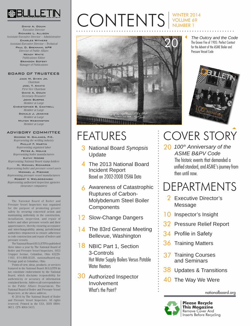
COVER STORY20 100th Anniversary of the
ASME B&PV Code The historic events that demanded a unified standard, and ASME's journey from then until now.
CONTENTS WINTER 2014VOLUME 69 NUMBER 1
Please RecycleThis MagazineRemove Cover And Inserts Before Recycling
nationalboard.org
The Outcry and the CodeThe Grover Fire of 1905: Perfect Context for the Advent of the ASME Boiler and Pressure Vessel Code
20
If there is one underlying message to be gleaned from the ASME Boiler Code’s 100-year anniversary, it is that quality can endure.
Back in 1914, the original framers of the ASME Code knew they had to do something to curtail the slaughter of inno-cent human beings. The result was more than a document that would survive a century. There had to be a continuum of excellence. And therein was the
challenge: How does an organization dependent on the generous professional contributions of volunteers maintain the quality of a critical document for future generations? One can only imagine the number of code committee members who have both come and gone over the years. And yet the ASME Code has both endured and flourished.
To what do we owe this herculean achievement? One word: commitment – commitment by a world-class organization and thousands of volunteers.
Commitment is the discipline that is particularly integral to the success of the pressure equipment industry. Our work leaves little room for miscalculation. Anything less than a quality product or performance may literally have life-or-death consequences. Knowing we have followed through to the best of our abilities every time results in professional gratification and a sense of ac-complishment for a job well done. More important for each of us, it helps preserve the public’s trust in how we perform our jobs.
In recognition of both the Code’s 100th anniversary and our industry’s dedication to the public’s wellbeing, we are designat-ing SAFETY: Quality Through Commitment as the theme for this year’s National Board/ASME General Meeting, May 11 – 16, in Bellevue, Washington.
And to symbolically reinforce our theme, we have chosen one of the true legends of Hollywood as our Opening Session speaker. Academy Award winner Robert Duvall was named by the Guin-ness Book of World Records as the most versatile actor in the world. Among the movies in which he has appeared: Apocalypse Now, The Natural, The Great Santini, True Grit, Network, The Godfather and The Godfather Part II, Bullitt, and To Kill a Mockingbird. These are but a few of the outstanding films and TV performances he has either performed in or directed over a career spanning nearly 60 years. [See biography on Page 14.]
BY DAVID A. DOUIN, EXECUTIVE DIRECTOR
SAFETY: Quality Through Commitment
In addition to an outstanding Opening Session, we have as-sembled another great lineup of speakers for the General Session. Among those scheduled to make presentations: National Board member representing Quebec and ASME President Madiha Kotb, P.E.; Senior Risk Engineering Consultant – Machinery Breakdown Doug Smiley of Zurich North America Insurance; Chief Engineer Melissa Wadkinson, P.E., of Fulton Thermal Corporation; Earl Harlow of SABIC Innovative Plastics; and author/BULLETIN contributor James R. Chiles.
Guests attending this year’s General Meeting will be glad to know they will receive an opportunity to visit the must-see sites of Seattle. [See page 16] Monday kicks off with a tour of the city and a chance to observe the Space Needle, historic Pioneer Square, the original Starbucks, the celebrated Pike Place Market, and much, much more. Tuesday, guests will tour the renowned Boehm's Candy Kitchen and the Chihuly Garden and Glass Gal-lery, featuring the work of Dale Chihuly. The day will also include a visit to the famous Chateau Ste. Michelle Winery for a specially prepared luncheon replete with wine pairings. On Wednesday, all guests and registrants are invited to tour two of the most exciting venues in Seattle: the world famous Boeing plant and the Future of Flight Aviation Center, where all will be treated to a wonderful buffet lunch.
In honor of the ASME Code anniversary, we have assembled a very unique Wednesday evening program combining the Wednesday Banquet and ASME’s annual Thursday reception. Be advised: this a first time, not-to-miss event. In addition to excel-lent food and beverage, the evening will include a very special entertainment program.
Remember: it takes commitment to ensure the continuity of quality. And whether that means staying current with one’s train-ing, taking the time and effort to participate in industry committee meetings, or becoming involved in exchanges of information with fellow professionals, it requires the personal commitment of us all to protect the legacy of the ASME Code.
Would the original code committee be surprised their docu-ment survived 100 years? I don’t think so. I believe they had great faith in the character and determination of their peers and, more important, future caretakers. They did their job well.
And now it is up to us.
2 NATIONAL BOARD BULLETIN WINTER 2014 NATIONALBOARD.ORG
EXECUTIVE DIRECTOR'S MESSAGEDEPARTMENT
SAFETY: Quality Through Commitment
3WINTER 2014 NATIONAL BOARD BULLETIN NATIONALBOARD.ORG
FEATURE BULLETIN
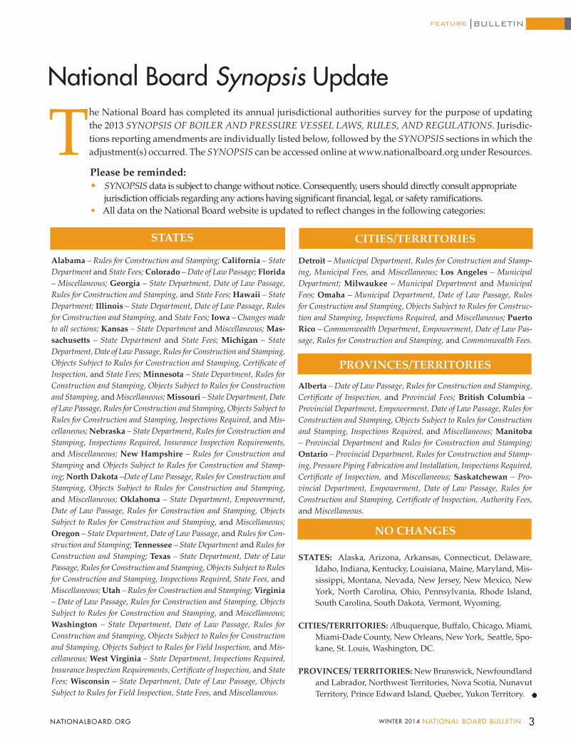
The National Board has completed its annual jurisdictional authorities survey for the purpose of updating the 2013 SYNOPSIS OF BOILER AND PRESSURE VESSEL LAWS, RULES, AND REGULATIONS. Jurisdic-tions reporting amendments are individually listed below, followed by the SYNOPSIS sections in which the adjustment(s) occurred. The SYNOPSIS can be accessed online at www.nationalboard.org under Resources.
STATES
Alabama – Rules for Construction and Stamping; California – State Department and State Fees; Colorado – Date of Law Passage; Florida – Miscellaneous; Georgia – State Department, Date of Law Passage, Rules for Construction and Stamping, and State Fees; Hawaii – State Department; Illinois – State Department, Date of Law Passage, Rules for Construction and Stamping, and State Fees; Iowa – Changes made to all sections; Kansas – State Department and Miscellaneous; Mas-sachusetts – State Department and State Fees; Michigan – State Department, Date of Law Passage, Rules for Construction and Stamping, Objects Subject to Rules for Construction and Stamping, Certificate of Inspection, and State Fees; Minnesota – State Department, Rules for Construction and Stamping, Objects Subject to Rules for Construction and Stamping, and Miscellaneous; Missouri – State Department, Date of Law Passage, Rules for Construction and Stamping, Objects Subject to Rules for Construction and Stamping, Inspections Required, and Mis-cellaneous; Nebraska – State Department, Rules for Construction and Stamping, Inspections Required, Insurance Inspection Requirements, and Miscellaneous; New Hampshire – Rules for Construction and Stamping and Objects Subject to Rules for Construction and Stamp-ing; North Dakota –Date of Law Passage, Rules for Construction and Stamping, Objects Subject to Rules for Construction and Stamping, and Miscellaneous; Oklahoma – State Department, Empowerment, Date of Law Passage, Rules for Construction and Stamping, Objects Subject to Rules for Construction and Stamping, and Miscellaneous; Oregon – State Department, Date of Law Passage, and Rules for Con-struction and Stamping; Tennessee – State Department and Rules for Construction and Stamping; Texas – State Department, Date of Law Passage, Rules for Construction and Stamping, Objects Subject to Rules for Construction and Stamping, Inspections Required, State Fees, and Miscellaneous; Utah – Rules for Construction and Stamping; Virginia – Date of Law Passage, Rules for Construction and Stamping, Objects Subject to Rules for Construction and Stamping, and Miscellaneous; Washington – State Department, Date of Law Passage, Rules for Construction and Stamping, Objects Subject to Rules for Construction and Stamping, Objects Subject to Rules for Field Inspection, and Mis-cellaneous; West Virginia – State Department, Inspections Required, Insurance Inspection Requirements, Certificate of Inspection, and State Fees; Wisconsin – State Department, Date of Law Passage, Objects Subject to Rules for Field Inspection, State Fees, and Miscellaneous.
National Board Synopsis Update
CITIES/TERRITORIES
Detroit – Municipal Department, Rules for Construction and Stamp-ing, Municipal Fees, and Miscellaneous; Los Angeles – Municipal Department; Milwaukee – Municipal Department and Municipal Fees; Omaha – Municipal Department, Date of Law Passage, Rules for Construction and Stamping, Objects Subject to Rules for Construc-tion and Stamping, Inspections Required, and Miscellaneous; Puerto Rico – Commonwealth Department, Empowerment, Date of Law Pas-sage, Rules for Construction and Stamping, and Commonwealth Fees.
PROVINCES/TERRITORIES
Alberta – Date of Law Passage, Rules for Construction and Stamping, Certificate of Inspection, and Provincial Fees; British Columbia – Provincial Department, Empowerment, Date of Law Passage, Rules for Construction and Stamping, Objects Subject to Rules for Construction and Stamping, Inspections Required, and Miscellaneous; Manitoba – Provincial Department and Rules for Construction and Stamping; Ontario – Provincial Department, Rules for Construction and Stamp-ing, Pressure Piping Fabrication and Installation, Inspections Required, Certificate of Inspection, and Miscellaneous; Saskatchewan – Pro-vincial Department, Empowerment, Date of Law Passage, Rules for Construction and Stamping, Certificate of Inspection, Authority Fees, and Miscellaneous.
NO CHANGES
STATES: Alaska, Arizona, Arkansas, Connecticut, Delaware, Idaho, Indiana, Kentucky, Louisiana, Maine, Maryland, Mis-sissippi, Montana, Nevada, New Jersey, New Mexico, New York, North Carolina, Ohio, Pennsylvania, Rhode Island, South Carolina, South Dakota, Vermont, Wyoming.
CITIES/TERRITORIES: Albuquerque, Buffalo, Chicago, Miami, Miami-Dade County, New Orleans, New York, Seattle, Spo-kane, St. Louis, Washington, DC.
PROVINCES/ TERRITORIES: New Brunswick, Newfoundland and Labrador, Northwest Territories, Nova Scotia, Nunavut Territory, Prince Edward Island, Quebec, Yukon Territory.
Please be reminded: • SYNOPSIS data is subject to change without notice. Consequently, users should directly consult appropriate jurisdiction officials regarding any actions having significant financial, legal, or safety ramifications. • All data on the National Board website is updated to reflect changes in the following categories:
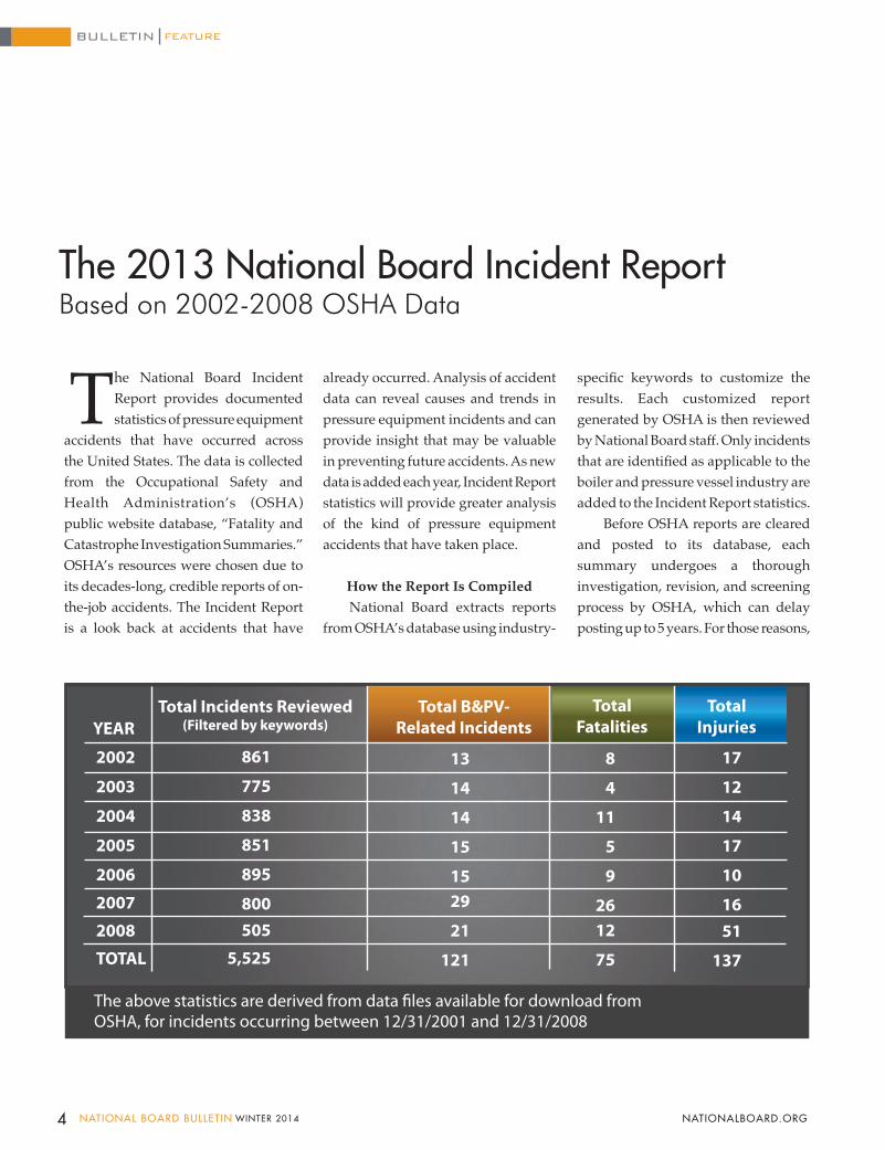
The National Board Incident Report provides documented statistics of pressure equipment
accidents that have occurred across the United States. The data is collected from the Occupational Safety and Health Administration’s (OSHA) public website database, “Fatality and Catastrophe Investigation Summaries.” OSHA’s resources were chosen due to its decades-long, credible reports of on-the-job accidents. The Incident Report is a look back at accidents that have
already occurred. Analysis of accident data can reveal causes and trends in pressure equipment incidents and can provide insight that may be valuable in preventing future accidents. As new data is added each year, Incident Report statistics will provide greater analysis of the kind of pressure equipment accidents that have taken place.
How the Report Is CompiledNational Board extracts reports
from OSHA’s database using industry-
specific keywords to customize the results. Each customized report generated by OSHA is then reviewed by National Board staff. Only incidents that are identified as applicable to the boiler and pressure vessel industry are added to the Incident Report statistics.
Before OSHA reports are cleared and posted to its database, each summary undergoes a thorough investigation, revision, and screening process by OSHA, which can delay posting up to 5 years. For those reasons,
2002
2003
2004
2005
2006
2007
2008
TOTAL
YEARTotal B&PV-
Related IncidentsTotal Incidents Reviewed
(Filtered by keywords)Total
FatalitiesTotal
Injuries
The above statistics are derived from data �les available for download fromOSHA, for incidents occurring between 12/31/2001 and 12/31/2008
861
775
838
851
895
800505
5,525
13
14
14
15
1529
21
121
8
4
11
5
9
2612
75
17
12
14
17
10
1651
137
4 NATIONAL BOARD BULLETIN WINTER 2014 NATIONALBOARD.ORG
BULLETIN
The 2013 National Board Incident Report
FEATURE
Based on 2002-2008 OSHA Data
OSH
A In
cide
nts
by Y
ear
2002 2003 2004 2005 2006 2007 2008
55
50
45
40
35
30
25
20
15
10
5
0
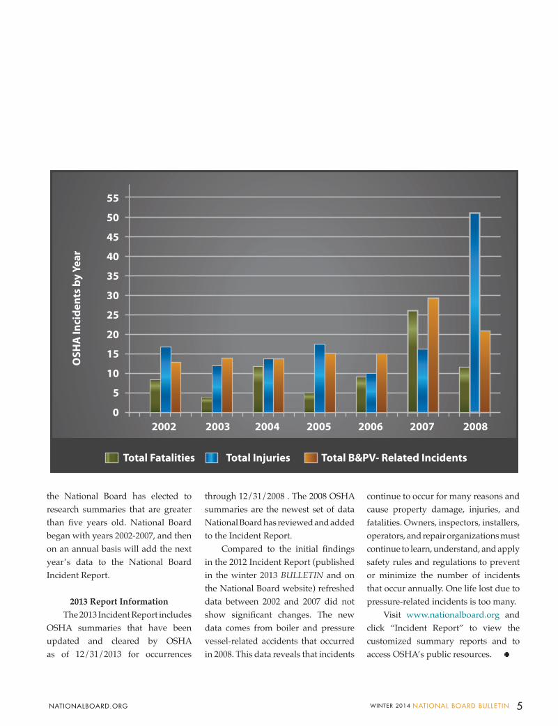
Total Fatalities Total Injuries Total B&PV- Related Incidents
the National Board has elected to research summaries that are greater than five years old. National Board began with years 2002-2007, and then on an annual basis will add the next year’s data to the National Board Incident Report.
2013 Report InformationThe 2013 Incident Report includes
OSHA summaries that have been updated and cleared by OSHA as of 12/31/2013 for occurrences
through 12/31/2008 . The 2008 OSHA summaries are the newest set of data National Board has reviewed and added to the Incident Report.
Compared to the initial findings in the 2012 Incident Report (published in the winter 2013 BULLETIN and on the National Board website) refreshed data between 2002 and 2007 did not show significant changes. The new data comes from boiler and pressure vessel-related accidents that occurred in 2008. This data reveals that incidents
continue to occur for many reasons and cause property damage, injuries, and fatalities. Owners, inspectors, installers, operators, and repair organizations must continue to learn, understand, and apply safety rules and regulations to prevent or minimize the number of incidents that occur annually. One life lost due to pressure-related incidents is too many.
Visit www.nationalboard.org and click “Incident Report” to view the customized summary reports and to access OSHA’s public resources.
5WINTER 2014 NATIONAL BOARD BULLETIN NATIONALBOARD.ORG
Mo s t o f t h e c o a l - f i re d boilers within the US have approached or even
exceeded 50 years of operational service and continue to reliably produce steam for power generation. With age, there is growing concern for the integrity of certain boiler steels, and one of those boiler steels is commonly referred to as carbon-molybdenum (C-Mo) alloy steel.
It is important that chief inspectors of jurisdictions or regulatory bodies understand that carbon-molybdenum and even carbon steels – which have been in elevated-temperature service above 775°F (410°C) for over 300,000 operating hours – can be at risk of sudden, catastrophic failure.
The carbon-molybdenum alloy steel had originally been used in the petrochemical industry, prior to its introduction in the power generation industry. At the time, original steel makers recognized the benefit of introducing molybdenum as an alloying element in carbon steel to improve hardenability, but more important, to improve elevated-temperature strength.
As carbon-molybdenum started to become more popular with boiler original equipment manufacturers (OEMs) because power boiler operating temperatures and pressures were increasing to keep up with demand for electric consumption, larger central power stations began to experience pipe failures of this material. A literature search reveals initial failures reported as early as the 1940s, with most failures well-documented in the 1950s
Awareness of Catastrophic Ruptures of Carbon-Molybdenum Steel Boiler Components BY GEORGE W. GALANES, P.E., DTS INC.
where sudden catastrophic failure of pipe material occurred within the heat-affected zone of fusion welded connections or attachments.
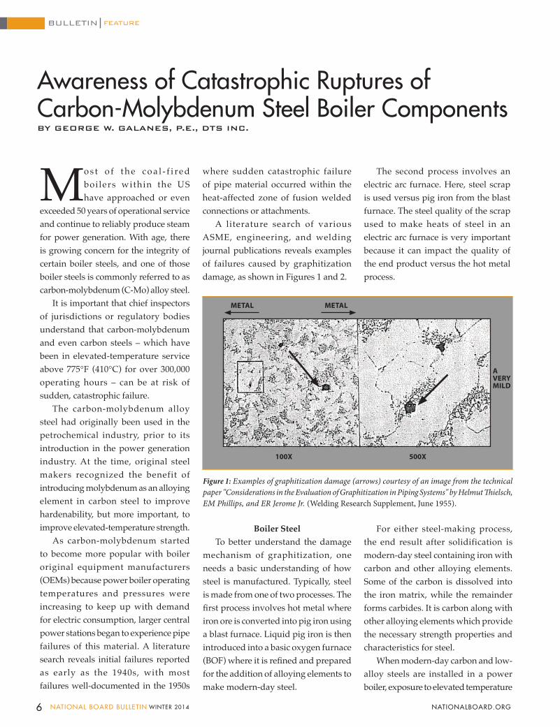
A literature search of various ASME, engineering, and welding journal publications reveals examples of failures caused by graphitization damage, as shown in Figures 1 and 2.
The second process involves an electric arc furnace. Here, steel scrap is used versus pig iron from the blast furnace. The steel quality of the scrap used to make heats of steel in an electric arc furnace is very important because it can impact the quality of the end product versus the hot metal process.
METAL METAL
100X 500X
AVERYMILD
Figure 1: Examples of graphitization damage (arrows) courtesy of an image from the technical paper "Considerations in the Evaluation of Graphitization in Piping Systems" by Helmut Thielsch, EM Phillips, and ER Jerome Jr. (Welding Research Supplement, June 1955).
Boiler SteelTo better understand the damage
mechanism of graphitization, one needs a basic understanding of how steel is manufactured. Typically, steel is made from one of two processes. The first process involves hot metal where iron ore is converted into pig iron using a blast furnace. Liquid pig iron is then introduced into a basic oxygen furnace (BOF) where it is refined and prepared for the addition of alloying elements to make modern-day steel.
For either steel-making process, the end result after solidification is modern-day steel containing iron with carbon and other alloying elements. Some of the carbon is dissolved into the iron matrix, while the remainder forms carbides. It is carbon along with other alloying elements which provide the necessary strength properties and characteristics for steel.
When modern-day carbon and low-alloy steels are installed in a power boiler, exposure to elevated temperature
6 NATIONAL BOARD BULLETIN WINTER 2014 NATIONALBOARD.ORG
FEATUREBULLETIN
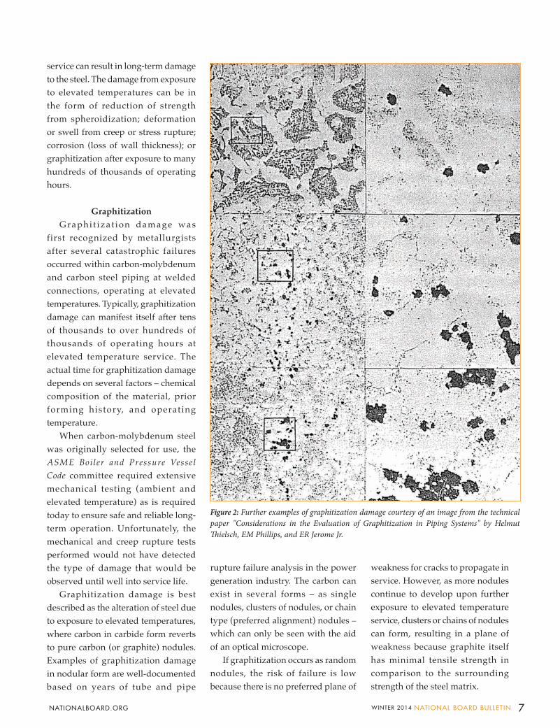
service can result in long-term damage to the steel. The damage from exposure to elevated temperatures can be in the form of reduction of strength from spheroidization; deformation or swell from creep or stress rupture; corrosion (loss of wall thickness); or graphitization after exposure to many hundreds of thousands of operating hours.
Graphitization Graphit izat ion damage was
first recognized by metallurgists after several catastrophic failures occurred within carbon-molybdenum and carbon steel piping at welded connections, operating at elevated temperatures. Typically, graphitization damage can manifest itself after tens of thousands to over hundreds of thousands of operating hours at elevated temperature service. The actual time for graphitization damage depends on several factors – chemical composition of the material, prior forming history, and operating temperature.
When carbon-molybdenum steel was originally selected for use, the ASME Boiler and Pressure Vessel Code committee required extensive mechanical testing (ambient and elevated temperature) as is required today to ensure safe and reliable long-term operation. Unfortunately, the mechanical and creep rupture tests performed would not have detected the type of damage that would be observed until well into service life.
Graphitization damage is best described as the alteration of steel due to exposure to elevated temperatures, where carbon in carbide form reverts to pure carbon (or graphite) nodules. Examples of graphitization damage in nodular form are well-documented based on years of tube and pipe
rupture failure analysis in the power generation industry. The carbon can exist in several forms – as single nodules, clusters of nodules, or chain type (preferred alignment) nodules – which can only be seen with the aid of an optical microscope.
If graphitization occurs as random nodules, the risk of failure is low because there is no preferred plane of
100X 500X
Figure 2: Further examples of graphitization damage courtesy of an image from the technical paper "Considerations in the Evaluation of Graphitization in Piping Systems" by Helmut Thielsch, EM Phillips, and ER Jerome Jr.
weakness for cracks to propagate in service. However, as more nodules continue to develop upon further exposure to elevated temperature service, clusters or chains of nodules can form, resulting in a plane of weakness because graphite itself has minimal tensile strength in comparison to the surrounding strength of the steel matrix.
7WINTER 2014 NATIONAL BOARD BULLETIN NATIONALBOARD.ORG
The formation of clusters or chains of graphite nodules is what concerns industry because these locations within the material can be susceptible to catastrophic failure in service.
Recent Industry Graphitization Failure
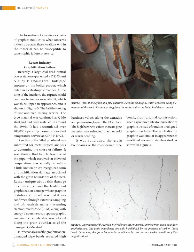
Recently, a large coal-fired central power station experienced a 6” (150mm) NPS by 1” (25mm) wall link pipe rupture on the boiler proper, which failed in a catastrophic manner. At the time of the incident, the rupture could be characterized as an axial split, which was thick-lipped in appearance, and is shown in Figure 3. The brittle-looking failure occurred during service. The pipe material was confirmed as C-Mo steel and had been installed in around the 1960s. It had accumulated over 200,000 operating hours of elevated temperature service at 830°F (440°C).
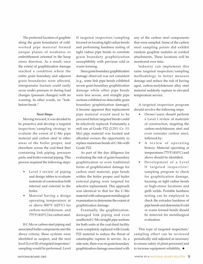
A section of the failed pipe bend was submitted for metallurgical analysis to determine the cause of failure. It was shown that brittle fracture of the pipe, which occurred at elevated temperature, was actually caused by a little-known or less-recognized form of graphitization damage associated with the grain boundaries of the steel. Rather unique about this damage mechanism, versus the traditional graphitization damage where graphite nodules are formed, was that it was confirmed through extensive sampling and lab analysis using a scanning electron microscope (SEM) along with energy dispersive x-ray spectrographic analysis. Elemental carbon was detected along the grain boundaries of the damaged C-Mo steel.
Further analysis of the graphitization-damaged pipe bends revealed high
Figure 3: View of one of the link pipe ruptures. Note the axial split, which occurred along the extrados of the bend. Steam is exiting from the rupture after the boiler had depressurized.
Figure 4: Micrograph of the carbon-molybdenum pipe material suffering from grain boundary graphitization. The grain boundaries are only highlighted by the presence of carbon (dark lines). Otherwise, the grain boundaries would not be seen in an unetched condition (500x magnification).
hardness values along the extrados and progressing toward the ID surface. The high hardness values indicate pipe material was subjected to either cold or warm bending.
It was concluded the grain boundaries of the cold-formed pipe
bends, from original construction, acted as preferred sites for nucleation of graphite instead of random or aligned graphite nodules. The nucleation of graphite was similar in appearance to sensitized austenitic stainless steel, as shown in Figure 4.
8 NATIONAL BOARD BULLETIN WINTER 2014 NATIONALBOARD.ORG
FEATUREBULLETIN
The preferred location of graphite along the grain boundaries of cold-worked pipe material formed unique planes of weakness or embrittlement oriented in the hoop stress direction. As a result, once the extent of graphitization damage reached a condition where the entire grain boundary and adjacent grain boundaries were affected, intergranular fracture could easily occur under pressure or during load changes (pressure changes) with no warning. In other words, no “leak-before-break.”
Next StepsMoving forward, it was decided to
be proactive and develop a targeted inspection/sampling strategy to evaluate the extent of C-Mo pipe material and carbon steel in other areas of the boiler proper, and elsewhere across the coal-fired fleet containing link piping, pressure parts, and boiler external piping. This process required the following steps:
• Level I review of piping and design tables to evaluate materials of construction both internal and external to the boiler.
• Material having a design operating temperature at or above 800°F (425°C) for carbon-molybdenum, and 775°F (410°C) for carbon steel.
If C-Mo or carbon steel piping and associated boiler components met the above criteria, these systems were identified as suspect, and the next level (Level II) of targeted inspection/sampling would be performed. Level
II targeted inspection/sampling focused on locating tight radius bends and performing hardness testing of tight radius pipe bends to correlate grain boundary graphit ization susceptibility with previous cold or warm forming.
Since grain boundary graphitization damage observed was not consistent (e.g., some link pipe bends exhibited severe grain boundary graphitization damage while other pipe bends were less severe, and straight pipe sections exhibited no detectable grain boundary graphitization damage), it became apparent that replacement pipe material would need to be procured before targeted bends could be selectively replaced. Fortunately, a mill run of Grade P22 (2.25% Cr- 1% Mo) pipe material was located and afforded owners the opportunity to replace numerous bends of C-Mo with Grade P22.
As part of the due diligence for evaluating the risk of grain boundary graphitization or even traditional forms of graphitization damage for carbon steel material, pipe bends within the boiler proper and boiler external piping were targeted for selective replacement. This approach was identical to that for the C-Mo material with subsequent metallurgical examination to determine the extent of graphitization damage.
Eventually, the graphitization-damaged link piping and even unaffected C-Mo straight pipe sections for both units at the coal-fired facility were completely replaced with Grade P22 material to reduce the threat of catastrophic rupture in service. As a side note, there was no grain boundary graphitization damage associated with
any of the carbon steel components that were sampled. Some of the carbon steel sampling points did exhibit random graphite nodules at welded attachments. These locations will be monitored over time.
Industry can implement this same targeted inspection/sampling methodology to better measure damage and reduce the risk of having aged, carbon-molybdenum alloy steel material suddenly rupture in elevated temperature service.
A targeted inspection program should involve the following steps:
• Owner/users should perform a Level I review of materials of construction, targeting the carbon-molybdenum steel and even consider carbon steel, followed by:
• A r e v i e w o f o p e r a t i n g history. Material operating at temperatures 775°F (410°C) and above should be identified.
• Deve lopment o f a Leve l I I t a r g e t e d i n s p e c t i o n /sampling program to check for graphitization damage, focusing on tight radius bends or high-stress locations and girth welds. Portable hardness testing can be employed to check the extrados hardness of pipe bends and determine if cold or warm formed bends should be removed for metallurgical evaluation.
This type of targeted inspection/sampling effort can be reviewed periodically and adjusted as necessary to ensure safety of plant personnel and to increase equipment reliability.
9WINTER 2014 NATIONAL BOARD BULLETIN NATIONALBOARD.ORG
DEPARTMENT
10 NATIONAL BOARD BULLETIN WINTER 2014 NATIONALBOARD.ORG
ASME/National Board vs. CSA Rating on T&P Relief ValvesBY THOMAS P. BEIRNE, P.E., TECHNICAL MANAGER, PRESSURE RELIEF DEPARTMENT
INSPECTOR’S INSIGHT
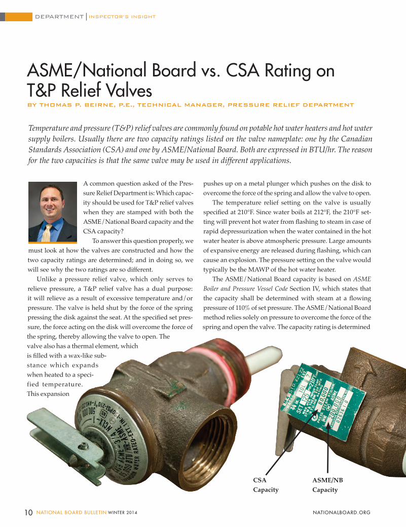
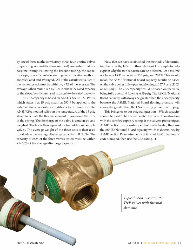
Temperature and pressure (T&P) relief valves are commonly found on potable hot water heaters and hot water supply boilers. Usually there are two capacity ratings listed on the valve nameplate: one by the Canadian Standards Association (CSA) and one by ASME/National Board. Both are expressed in BTU/hr. The reason for the two capacities is that the same valve may be used in different applications.
pushes up on a metal plunger which pushes on the disk to overcome the force of the spring and allow the valve to open.
The temperature relief setting on the valve is usually specified at 210°F. Since water boils at 212°F, the 210°F set-ting will prevent hot water from flashing to steam in case of rapid depressurization when the water contained in the hot water heater is above atmospheric pressure. Large amounts of expansive energy are released during flashing, which can cause an explosion. The pressure setting on the valve would typically be the MAWP of the hot water heater.
The ASME/National Board capacity is based on ASME Boiler and Pressure Vessel Code Section IV, which states that the capacity shall be determined with steam at a flowing pressure of 110% of set pressure. The ASME/National Board method relies solely on pressure to overcome the force of the spring and open the valve. The capacity rating is determined
A common question asked of the Pres-sure Relief Department is: Which capac-ity should be used for T&P relief valves when they are stamped with both the ASME/National Board capacity and the CSA capacity?
To answer this question properly, we must look at how the valves are constructed and how the two capacity ratings are determined; and in doing so, we will see why the two ratings are so different.
Unlike a pressure relief valve, which only serves to relieve pressure, a T&P relief valve has a dual purpose: it will relieve as a result of excessive temperature and/or pressure. The valve is held shut by the force of the spring pressing the disk against the seat. At the specified set pres-sure, the force acting on the disk will overcome the force of the spring, thereby allowing the valve to open. The valve also has a thermal element, which is filled with a wax-like sub-stance which expands when heated to a speci-fied temperature. This expansion
CSA Capacity
ASME/NBCapacity
11WINTER 2014 NATIONAL BOARD BULLETIN NATIONALBOARD.ORG
by one of three methods whereby three, four, or nine valves (depending on certification method) are submitted for baseline testing. Following the baseline testing, the capac-ity, slope, or coefficient (depending on certification method) are calculated and averaged. All of the calculated values of the valves tested must be within +/- 5% of the average. The average is then multiplied by 0.90 to obtain the rated capacity or the slope/coefficient used to calculate the rated capacity.
The CSA capacity is based on ANSI/CSA Z21.22, Part 3, which states that 15 psig steam at 250°F be applied to the valve at stable operating conditions for 15 minutes. The ANSI/CSA method relies on the temperature of the 15 psig steam to actuate the thermal element to overcome the force of the spring. The discharge of the valve is condensed and weighed. The test is then repeated for two additional sample valves. The average weight of the three tests is then used to calculate the average discharge capacity in BTU/hr. The capacity of each of the three valves tested must be within +/- 10% of the average discharge capacity.
Now that we have established the methods of determin-ing the capacity, let’s run through a quick example to help explain why the two capacities are so different. Let’s assume we have a T&P valve set at 125 psig and 210°F. This would mean the ASME/National Board capacity would be based on the valve being fully open and flowing at 137.5 psig (110% of 125 psig). The CSA capacity would be based on the valve being fully open and flowing at 15 psig. The ASME/National Board capacity will always be greater than the CSA capacity because the ASME/National Board flowing pressure will always be greater than the CSA flowing pressure of 15 psig.
This brings us to our original question – Which capacity should be used? The answer: match the code of construction with the certified capacity rating. If the valve is protecting an ASME Section IV code-stamped hot water heater, then use the ASME/National Board capacity which is determined by ASME Section IV requirements. If it is not ASME Section IV code stamped, then use the CSA rating.
Typical ASME Section IV T&P valves with thermalelements.

Now prototypes, perhaps soon in production: I'd call this a step-change in progress, portending big shifts in the way things
have always been done. Older step-changes that come to mind include electric-arc weld-ing; air brakes on railroad cars; the shift from wrought iron to Bessemer steel; or more recently, electric utilities now converting from coal to natural gas for baseload power generation.
The nature of a step-change is that just about everybody in the field hears about it, knows it’s important, and adjusts. The transition isn't necessarily quick or pain-less, but practices get smoother over time as lessons are learned. Step-changes prompt a wave of new books, conference topics, and training courses.
I'm thinking about change that comes at a much smaller scale and a slower pace. It's subtle and can be dangerous. A producer contacted me recently about a forthcoming National Geographic TV show about the crash of Lauda Air Flight 004. “What are the takeaways for you?” he asked. What strikes me about this 1991 tragedy was how several seemingly minor changes added up. One of those changes was an aircraft design that shifted the wing-mounted engines to the leading edge. Another change was a string of small but persistent malfunctions in the thrust-reverser mechanisms before the crash. (Thrust reversers slow down a jet after landing.)
Slow-Change Dangers By James R. Chiles
Beforehand, no one at the manufacturer or among the airlines understood that a change in engine placement on new, more-efficient jets would make what was thought to be a minor incident – accidental triggering of an engine's thrust reverser in cruise flight – into a very dangerous event. That's because at high speeds, the reverser's backblast would disrupt airflow over the jet's wings. And it happened over Thailand: the airliner rolled over and plunged to Earth in a near-supersonic dive, killing everyone on board. (The accidental reverser deployment might have been partly due to a “hot-short” electri-cal fault in the wiring, but key evidence was destroyed in the crash.)
Since the effect of this new but slow-moving combination was unknown, the FAA didn't require Boeing to do a rigorous test of what would happen on 767 models if a reverser deployed at cruise speeds. Had that danger been discovered, better pre-cautions could have been taken to prevent deployments in the air, or at least to train the pilots in the very fast actions needed to save the aircraft.
Slow changes that tend to add up in sur-prising ways are everywhere. In this issue we learn about the 1905 boiler explosion at R.B. Grover Shoe factory: an old boiler with an un-detectable tendency to develop corrosion cracks was summoned back into temporary service on a cold March day to heat the whole factory complex, because the newer and safer boiler needed maintenance.
FEATUREBULLETIN
Mr. Chiles writes extensively about
technology and history. Contact
him at [email protected] or at his
blog: Disaster-wise.
Last issue, the BULLETIN featured how its test lab is evaluating 3D-printed valve components submitted for prototype testing. That's a big, visible change landing on the doorsteps of industries across the world. But what about slow, creeping changes that add up over time?
12 NATIONAL BOARD BULLETIN WINTER 2014 NATIONALBOARD.ORG
Nestled among the infamous set of risk factors that day – barrels of naphtha stored nearby, and a water tower that collapsed into the flames, trapping workers – this slow-change danger caught my eye: Grover Shoe had recently added a fourth factory floor to meet higher demand for its Emerson shoe, and this change must have increased the demand for steam. According to a detailed report in the Engineers' Review that year, the widow of the chief engineer said that her hus-band “had been afraid of the old boiler for some months, as he did not consider it fit for use with a high pressure and did not like the idea of running it at such a high pressure as was necessary in order to do the work.”
Taking Grover Shoe as a histori-cal foundation, here's a more recent example of slow-change danger in which no team or expert paused to take a 360-degree view of risks or check current facts against old wisdom. It concerns the 1999 Bonfire tragedy at Texas A&M University. It's an example of how things “grow like Topsy,” with unminded risks that grow toward cata-strophic failure (here, collapsing and killing twelve students). Strange but true: it happened in a setting packed with engineering faculty who could have checked the risks on a periodic basis – if asked.
Starting in 1909 and annually through November 1999, the Bonfire was an affair run by students. Ad-hoc piles of wood and trash typical of the early years became all-log structures by 1943, and these grew taller with time. By the 1990s, students mobilized each October to harvest and haul 1,000 tons of trees from East Texas forests, then build a stack to be ignited just before the big football game between Texas A&M and the University of Texas at Austin.
Seeking bigger and better displays, the volunteers pushed the edges of
safety a little bit each year, despite the university's attempt to manage risks by setting limits on the stack's height and width. As the late-November game day approached, workers perched on the stack, received the hoisted logs, and wired them together. Imagine a three-layer wedding cake with tall, steep sides. Among the slow-changing risks: the logs arriving at the campus in 1999 were unusually crooked that year, encouraging the builders to jam upper logs into the tiers below.
The builders' decision to wedge up-per logs into lower logs played a part in the tragic collapse of the stack during construction, because it increased the hoop stress on the perimeter fastenings. According to a summary by Henry Petroski, professor of engineering at Duke University, “the [investigating] commission found the collapse to be driven by a combination of factors, rather than any single factor, and each of those factors points to a mindset among the university's students and administration characterized by com-placency, hubris, and a disrespect for the forces of nature. . . . Bonfire tradition was to build on the successes of past years, but modifications made from year to year negated what could be learned from the experience.”
Petroski has written many books about engineering and its lessons, so I asked him about the broader impli-cations of incremental, unmonitored changes. He pointed to a tragic thread in bridge-building history: over the years, some designers shaved safety margins, in part because earlier bridges of that type hadn't collapsed. He cited a series of suspension-bridge designs that moved from the sturdiness of the Brooklyn Bridge (completed in 1883, still standing) to the slender flexibility of the Tacoma Narrows Bridge (com-pleted in 1940, collapsed in 1940).
“Designers should know the his-tory of the genre in which they work,”
Petroski wrote me. “Fundamental as-sumptions and principles are embedded in that history, and they are forgotten at the designer’s peril.”
Unmonitored slow changes in your organization could be putting vital systems at risk, rendering obsolete old standard operating procedures and precautions. In the summer 2012 BULLETIN, I wrote about red flags that once signaled danger on the railroads, and how today's boiler and pressure vessel inspectors have come to recognize today's virtual red flags.
Slow-change dangers, on the other hand, are more likely to be tiny yellow flags of caution. I'd argue that slow-change hazards may be easier to spot when the factors come from outside a company. That's because many compa-nies are already mobilized and motivat-ed to spot change on the periphery. Such outside changes could be in materials, market, or regulation.
And some fields already monitor spe-cific slow-change dangers. Take smart bridges: the concrete bridge in Minne-apolis that replaced the collapsed I-35W span draws on hundreds of sensors to transmit reports on strain, corrosion, and tiny movements. New jet engines come with many diagnostic instruments linked to the airplane's communications suite, so that a change in any vital func-tion will alert not only the flight crew but experts on the ground, who can diagnose the situation even before the plane lands.
Instruments can't tell us everything. Intuition counts too. If you hear that maintainers are coming up with short-cuts and kluges to keep a previously reliable system going, that might be a timely subject for your root-cause-analysis (RCA) team to tackle. And many more tools like RCA are available, so take heart! It's possible to stay on top of slow-change dangers, whether creeping up on your organization from inside or out. That's how we see the fact; react; and act, before the walls fall in.
13WINTER 2014 NATIONAL BOARD BULLETIN NATIONALBOARD.ORG
Hyatt Regency BellevueThe Hyatt Regency Bellevue is situated in the area’s dynamic Bellevue Collection on Seattle’s fashion-
able Eastside. Only 20 minutes from Sea-Tac International Airport, it is connected by sky bridges to more than 250 shops, 45 restaurants and lounges, and countless entertainment options. Nearby outdoor activi-ties include hiking, biking, world-class golf, fishing, and skiing. The hotel features a heated 25-meter lap pool, in-room high definition flat screen TVs, fully equipped 24-hour gym, spa, lobby coffee shop, and three lounges. Four restaurants are also on-site, including award-winning steakhouse Daniel’s Broiler.
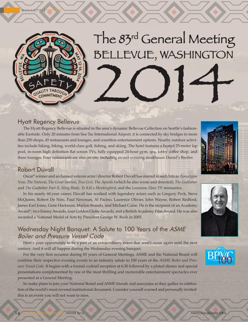
Robert DuvallOscar® winner and acclaimed veteran actor/director Robert Duvall has starred in such hits as Apocalypse
Now, The Natural, The Great Santini, True Grit, The Apostle (which he also wrote and directed), The Godfather and The Godfather Part II, Sling Blade, To Kill a Mockingbird, and the Lonesome Dove TV miniseries.
In his nearly 60-year career, Duvall has worked with legendary actors such as Gregory Peck, Steve McQueen, Robert De Niro, Paul Newman, Al Pacino, Laurence Olivier, John Wayne, Robert Redford, James Earl Jones, Gene Hackman, Marlon Brando, and Michael Caine. He is the recipient of an Academy Award®, two Emmy Awards, four Golden Globe Awards, and a British Academy Film Award. He was also awarded a National Medal of Arts by President George W. Bush in 2005.
Wednesday Night Banquet: A Salute to 100 Years of the ASME Boiler and Pressure Vessel Code
Here’s your opportunity to be a part of an extraordinary event that won’t occur again until the next century. And it will all happen during the Wednesday evening banquet.
For the very first occasion during 83 years of General Meetings, ASME and the National Board will combine their respective evening events in an industry salute to 100 years of the ASME Boiler and Pres-sure Vessel Code. It begins with a formal cocktail reception at 6:30 followed by a plated dinner and special presentations complemented by one of the most thrilling and memorable entertainment spectacles ever presented at a General Meeting.
So make plans to join your National Board and ASME friends and associates as they gather in celebra-tion of the world’s most revered institutional document. Consider yourself warned and personally invited: this is an event you will not want to miss.
14 NATIONAL BOARD BULLETIN WINTER 2014 NATIONALBOARD.ORG
FEATUREBULLETIN
Monday, May 12Opening Session
10:15 a.m. REMARKS Robert Duvall*
General Session
1:00 p.m. 100 YEARS OF THE ASME BOILER AND PRESSURE VESSEL CODE Madiha Kotb, P.E., Professional Engineer, Province of Quebec PRESIDENT OF ASME 1:30 p.m. BIOFUELS – HOW IMPACTING THE GREENHOUSE EFFECT IMPACTS POWER BOILERS Douglas E. Smiley, Senior Risk Engineering Consultant – Machinery Breakdown ZURICH NORTH AMERICA INSURANCE 2:00 p.m. INVITED: TO BE ANNOUNCED 2:30 p.m. BREAK
2:45 p.m. SECRETS OF THE CODE James R. Chiles, Author INVITING DISASTER, THE GOD MACHINE
3:30 p.m. OVERVIEW OF THERMAL FLUID HEATERS Melissa Wadkinson, P.E., Chief Engineer FULTON THERMAL CORPORATION
4:00 p.m. RELIEF DEVICE CAPACITY COMPARISON FROM THE INSPECTOR’S VIEW Earl Harlow SABIC INNOVATIVE PLASTICS
* PHOTO SESSION WITH ROBERT DUVALL FOLLOWS OPENING SESSION
(No autograph requests, please)
General Meeting Notices
• Participants and guests are encouraged to dress in a business-casual style for all hotel events except the Wednesday banquet (where ties and jackets will be the evening attire).
• Distribution of any and all literature other than informational materials published by the Na-tional Board and ASME is strictly prohibited at the General Meeting.
• To obtain a preregistration discount of $50, all forms and fees must be received by April 25.
• On-Site Registration Desk Hours:
Sunday, May 11 . . . . 9:00 a.m. - 2:00 p.m. Monday, May 12 . . . 8:00 a.m. - 10:00 a.m. Tuesday, May 13. . . 8:00 a.m. - 10:00 a.m.
• General Meeting Registration is required in order to receive the special $189 room rate at the Hyatt Regency Bellevue.
Reminder
General Meeting details can also be found on InfoLink! located on the National Board website at nationalboard.org.
ASME Boiler and Pressure Vessel Code Meetings
• Meetings are scheduled all week.
• Check hotel information board for locations and times.
• Meetings are open to the public.
83rd GENERAL MEETING
PRELIMINARY PROGRAMThe National Board of Boiler and Pressure Vessel Inspectors
&ASME Boiler and Pressure Vessel Committee
15WINTER 2014 NATIONAL BOARD BULLETIN NATIONALBOARD.ORG

GENERAL MEETING GUEST TOURS
Monday, May 12 Seattle City Highlights Tour, 1:00 p.m. – 5:00 p.m.
The day begins with a brief city tour of Bellevue en route to Seattle’s International District and historic Pioneer Square, the city's oldest residential area. Guests will then drive along Seattle’s bustling Elliott Bay waterfront to view the Puget Sound attractions. Next stop: the Hiram M. Chittenden Locks, commonly called the Ballard Locks. A must-see highlight of this stop is the fish ladder, built to allow salmon to pass between freshwater and saltwater. Next is a drive by Seattle’s most famous landmark: the Space Needle. Created for the 1962 World's Fair, the Space Needle stands 605 feet tall and boasts fabulous 360-degree views of the beautiful city of Seattle, and beyond. The final stop of the afternoon will be the celebrated Pike Place Market where a variety of farmers, merchants, vendors, cafés, restaurants, and even the original Starbucks call this nine-acre historic district home. Guests will be given time to shop and explore this fascinating area, which has remained a vital part of Seattle's social and economic fabric for over 100 years.NOTE: This tour requires a moderate amount of walking at the Locks and Pike Place Market. Jacket and comfortable walking shoes are recommended.
Tuesday, May 13 The Something for Everyone Tour, 9:00 a.m. – 3:00 p.m.
The day begins with a tour of Boehm's Candy Kitchen, known for its over 150 fabulous Swiss chocolates produced by master candy makers. A highlight is a visit to the authentic Swiss Chalet and Alpine Chapel, where visitors will learn about the incredible history of founder Julius Boehm. Guests will next visit Chihuly Garden and Glass. Located at Seattle Center, the exhibition garden features paths lined with crystal trees, plants, and flowers. Guests will observe how artist Dale Chihuly creates elaborate installations that flow on floors, walls, ceilings, and the outdoors. Guests will then be transported to nearby Chateau Ste. Michelle Winery for a luncheon replete with wine pairings. Located on 87 acres of arboretum-like grounds, Chateau Ste. Michelle is Washington’s oldest winery and is regularly voted one of the top ten wineries in the United States. (Washington State is the nation's second-largest wine producer and is ranked among the world's top wine regions.) After a private tour and wine tasting, visitors will have time to stroll through the grounds and receive a 10 percent discount at the extensive wine and accessory shop.NOTE: This tour requires a moderate amount of walking. Jacket and comfortable walking shoes are recommended.
Wednesday, May 14 Up, Up, and Away Tour, 8:00 a.m. – 3:00 p.m.
At the world-famous Boeing plant in Everett, guests will be able to witness airplanes, including the new 777 and the 787 Dreamliner, being assembled right before their very eyes. The Boeing complex is recognized by the Guinness Book of World Records as the largest building in the world by volume (enclosing 472 million cubic feet of space). Visitors will also explore Boeing’s newest high-tech facility, the Future of Flight Aviation Center. This 73,000-square-foot center features hands-on exhibits, videos, graphics, and interactive stations where guests can digitally design their own jet, try out the next generation of in-flight entertainment systems, and touch the high-tech “skin” of the new Boeing 787. Next, guests will be transported to the Museum of Flight, one of the largest air and space museums in the world. Following lunch at the museum, guests can peruse over 150 historically significant air and spacecraft, including the first jet Air Force One (a specially-built Boeing 707-120 that carried Presidents Eisenhower, Kennedy, Johnson, and Nixon around the world). At the Red Barn, birthplace of the Boeing Company, guests can explore this historic space built in 1909 and examine a recreated factory workshop displaying how the Red Barn was used in the 1920s during the production of the Model 40.NOTE: This tour requires a moderate amount of walking. Jacket and comfortable walking shoes are recommended.
Please see InfoLink! on the National Board website for tour guidelines and restrictions.
NOTE: Registrants are not permitted to attend the Monday or Tuesday tours intended for designated guests. This policy is strictly enforced.
16 NATIONAL BOARD BULLETIN WINTER 2014 NATIONALBOARD.ORG
FEATUREBULLETIN
Please see InfoLink! on the National Board website for tour guidelines and restrictions.
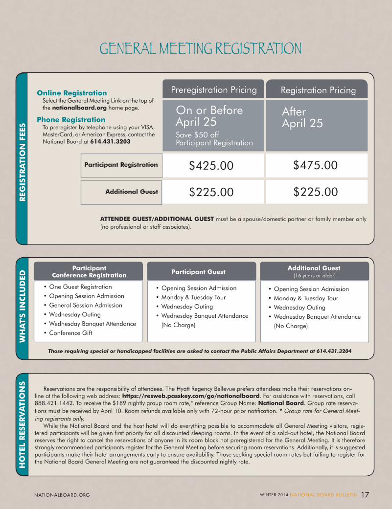
GENERAL MEETING REGISTRATION
Preregistration Pricing Registration Pricing
Participant Registration
$225.00 $225.00
$475.00$425.00
Additional Guest
On or Before April 25Save $50 off Participant Registration
After April 25
ATTENDEE GUEST/ADDITIONAL GUEST must be a spouse/domestic partner or family member only (no professional or staff associates).
• One Guest Registration• Opening Session Admission• General Session Admission• Wednesday Outing• Wednesday Banquet Attendance• Conference Gift
• Opening Session Admission• Monday & Tuesday Tour• Wednesday Outing• Wednesday Banquet Attendance
(No Charge)
• Opening Session Admission• Monday & Tuesday Tour• Wednesday Outing• Wednesday Banquet Attendance
(No Charge)
Those requiring special or handicapped facilities are asked to contact the Public Affairs Department at 614.431.3204
Reservations are the responsibility of attendees. The Hyatt Regency Bellevue prefers attendees make their reservations on-line at the following web address: https://resweb.passkey.com/go/nationalboard. For assistance with reservations, call 888.421.1442. To receive the $189 nightly group room rate,* reference Group Name: National Board. Group rate reserva-tions must be received by April 10. Room refunds available only with 72-hour prior notification. * Group rate for General Meet-ing registrants only.
While the National Board and the host hotel will do everything possible to accommodate all General Meeting visitors, regis-tered participants will be given first priority for all discounted sleeping rooms. In the event of a sold-out hotel, the National Board reserves the right to cancel the reservations of anyone in its room block not preregistered for the General Meeting. It is therefore strongly recommended participants register for the General Meeting before securing room reservations. Additionally, it is suggested participants make their hotel arrangements early to ensure availability. Those seeking special room rates but failing to register for the National Board General Meeting are not guaranteed the discounted nightly rate.
ParticipantConference Registration Participant Guest
Additional Guest (16 years or older)
REG
ISTR
ATI
ON
FEE
S W
HA
T'S
INC
LUD
ED
HO
TEL
RES
ERV
ATI
ON
S
Online Registration Select the General Meeting Link on the top of the nationalboard.org home page.
Phone Registration To preregister by telephone using your VISA, MasterCard, or American Express, contact the National Board at 614.431.3203
17WINTER 2014 NATIONAL BOARD BULLETIN NATIONALBOARD.ORG
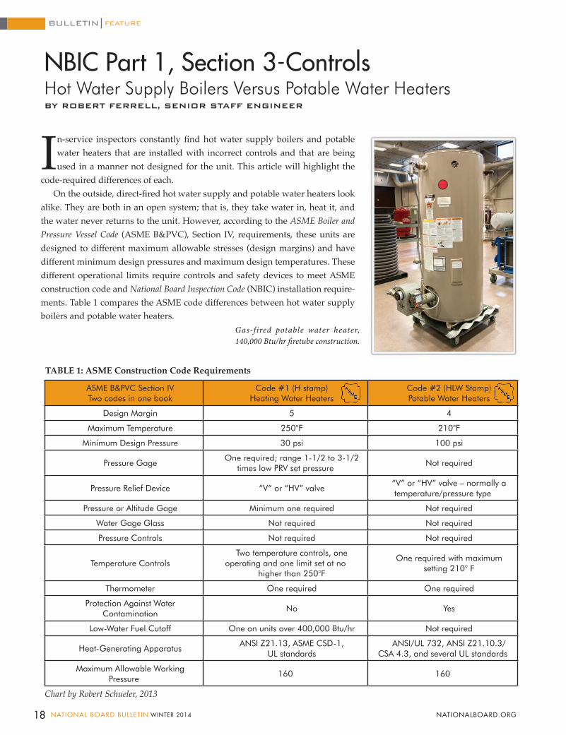
In-service inspectors constantly find hot water supply boilers and potable water heaters that are installed with incorrect controls and that are being used in a manner not designed for the unit. This article will highlight the
code-required differences of each. On the outside, direct-fired hot water supply and potable water heaters look
alike. They are both in an open system; that is, they take water in, heat it, and the water never returns to the unit. However, according to the ASME Boiler and Pressure Vessel Code (ASME B&PVC), Section IV, requirements, these units are designed to different maximum allowable stresses (design margins) and have different minimum design pressures and maximum design temperatures. These different operational limits require controls and safety devices to meet ASME construction code and National Board Inspection Code (NBIC) installation require-ments. Table 1 compares the ASME code differences between hot water supply boilers and potable water heaters.
ASME B&PVC Section IVTwo codes in one book
Code #1 (H stamp)Heating Water Heaters
Code #2 (HLW Stamp) Potable Water Heaters
Design Margin 5 4
Maximum Temperature 250°F 210°F
Minimum Design Pressure 30 psi 100 psi
Pressure GageOne required; range 1-1/2 to 3-1/2
times low PRV set pressureNot required
Pressure Relief Device “V” or “HV” valve“V” or “HV” valve – normally a temperature/pressure type
Pressure or Altitude Gage Minimum one required Not required
Water Gage Glass Not required Not required
Pressure Controls Not required Not required
Temperature ControlsTwo temperature controls, one
operating and one limit set at no higher than 250°F
One required with maximum setting 210° F
Thermometer One required One required
Protection Against Water Contamination
No Yes
Low-Water Fuel Cutoff One on units over 400,000 Btu/hr Not required
Heat-Generating ApparatusANSI Z21.13, ASME CSD-1,
UL standardsANSI/UL 732, ANSI Z21.10.3/
CSA 4.3, and several UL standards
Maximum Allowable Working Pressure
160 160
TABLE 1: ASME Construction Code Requirements
Chart by Robert Schueler, 2013
Gas-fired potable water heater, 140,000 Btu/hr firetube construction.
18 NATIONAL BOARD BULLETIN WINTER 2014 NATIONALBOARD.ORG
NBIC Part 1, Section 3-ControlsHot Water Supply Boilers Versus Potable Water Heaters BY ROBERT FERRELL, SENIOR STAFF ENGINEER
FEATUREBULLETIN
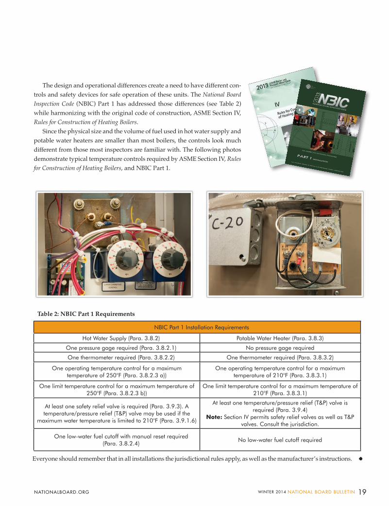
The design and operational differences create a need to have different con-trols and safety devices for safe operation of these units. The National Board Inspection Code (NBIC) Part 1 has addressed those differences (see Table 2) while harmonizing with the original code of construction, ASME Section IV, Rules for Construction of Heating Boilers.
Since the physical size and the volume of fuel used in hot water supply and potable water heaters are smaller than most boilers, the controls look much different from those most inspectors are familiar with. The following photos demonstrate typical temperature controls required by ASME Section IV, Rules for Construction of Heating Boilers, and NBIC Part 1.
Everyone should remember that in all installations the jurisdictional rules apply, as well as the manufacturer’s instructions.
NBIC Part 1 Installation Requirements
Hot Water Supply (Para. 3.8.2) Potable Water Heater (Para. 3.8.3)
One pressure gage required (Para. 3.8.2.1) No pressure gage required
One thermometer required (Para. 3.8.2.2) One thermometer required (Para. 3.8.3.2)
One operating temperature control for a maximum temperature of 250°F (Para. 3.8.2.3 a))
One operating temperature control for a maximum temperature of 210°F (Para. 3.8.3.1)
One limit temperature control for a maximum temperature of 250°F (Para. 3.8.2.3 b))
One limit temperature control for a maximum temperature of 210°F (Para. 3.8.3.1)
At least one safety relief valve is required (Para. 3.9.3). A temperature/pressure relief (T&P) valve may be used if the
maximum water temperature is limited to 210°F (Para. 3.9.1.6)
At least one temperature/pressure relief (T&P) valve is required (Para. 3.9.4)
Note: Section IV permits safety relief valves as well as T&P valves. Consult the jurisdiction.
One low-water fuel cutoff with manual reset required (Para. 3.8.2.4)
No low-water fuel cutoff required
Table 2: NBIC Part 1 Requirements
19WINTER 2014 NATIONAL BOARD BULLETIN NATIONALBOARD.ORG
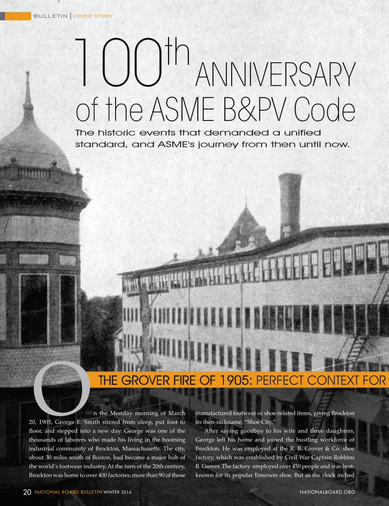
On the Monday morning of March 20, 1905, George E. Smith stirred from sleep, put foot to floor, and stepped into a new day. George was one of the thousands of laborers who made his living in the booming industrial community of Brockton, Massachusetts. The city, about 30 miles south of Boston, had become a major hub of the world’s footwear industry. At the turn of the 20th century, Brockton was home to over 400 factories; more than 90 of those
manufactured footwear or shoe-related items, giving Brockton its then-nickname, “Shoe City.”
After saying goodbye to his wife and three daughters, George left his home and joined the bustling workforce of Brockton. He was employed at the R. B. Grover & Co. shoe factory, which was established by Civil War Captain Robbins B. Grover. The factory employed over 450 people and was best-known for its popular Emerson shoe. But as the clock inched
THE GROVER FIRE OF 1905: PERFECT CONTEXT FOR THE ADVENT OF THE ASME BOILER AND PRESSURE VESSEL CODE
20 NATIONAL BOARD BULLETIN WINTER 2014 NATIONALBOARD.ORG
COVER STORYBULLETIN
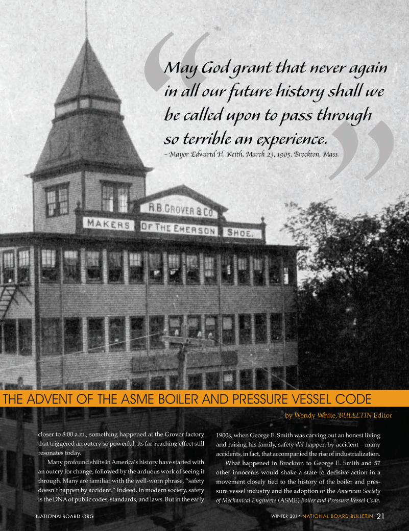
closer to 8:00 a.m., something happened at the Grover factory that triggered an outcry so powerful, its far-reaching effect still resonates today.
Many profound shifts in America’s history have started with an outcry for change, followed by the arduous work of seeing it through. Many are familiar with the well-worn phrase, “safety doesn’t happen by accident.” Indeed. In modern society, safety is the DNA of public codes, standards, and laws. But in the early
1900s, when George E. Smith was carving out an honest living and raising his family, safety did happen by accident – many accidents, in fact, that accompanied the rise of industrialization.
What happened in Brockton to George E. Smith and 57 other innocents would shake a state to decisive action in a movement closely tied to the history of the boiler and pres-sure vessel industry and the adoption of the American Society of Mechanical Engineers (ASME) Boiler and Pressure Vessel Code.
THE GROVER FIRE OF 1905: PERFECT CONTEXT FOR THE ADVENT OF THE ASME BOILER AND PRESSURE VESSEL CODEby Wendy White, BULLETIN Editor
21WINTER 2014 NATIONAL BOARD BULLETIN NATIONALBOARD.ORG
Evolving ConcernDecades before George E. Smith came face-to-face with
steam power’s deadly force, the consequences of the misuse and misunderstanding of steam and boilers was terrorizing communities at an alarming rate. In their book, An Evolv-ing Concern: Technology, Safety, and the Hartford Steam Boiler Inspection and Insurance Company 1866-1991, Glenn Weaver and J. Bard McNulty describe the 1850s thus: “Although there were literally thousands of steam boilers in operation throughout the United States, there was an almost abysmal ignorance about the properties of steam and the causes of boiler explosions. Explosions were occurring at the rate of almost one every four days, but most people concerned with the use of steam power simply accepted them as ‘acts of God.’ ” Most people.
In the latter part of the 1800s, engineers, manufactur-ers, and others who either shared an interest in science or who worked with steam equipment were concerned and began meeting to discuss current topics, particularly steam power and the problem of boiler explosions. Longstanding
organizations such as The Hartford Steam Boiler Inspection and Insurance Company, The Babcock & Wilcox Company, The American Boiler Manufacturers Association, and of course, ASME, formed during these seminal years. Each shared the concern of boiler dangers and certainly sought improvement. But it would take time, study, and great loss of life before engineering solutions would merge with legislation to bring industrial safety to new prominence.
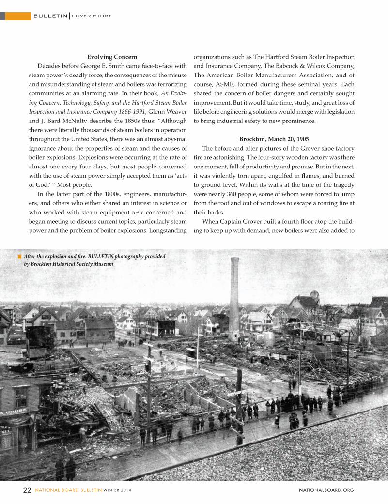
Brockton, March 20, 1905The before and after pictures of the Grover shoe factory
fire are astonishing. The four-story wooden factory was there one moment, full of productivity and promise. But in the next, it was violently torn apart, engulfed in flames, and burned to ground level. Within its walls at the time of the tragedy were nearly 360 people, some of whom were forced to jump from the roof and out of windows to escape a roaring fire at their backs.
When Captain Grover built a fourth floor atop the build-ing to keep up with demand, new boilers were also added to
After the explosion and fire. BULLETIN photography provided by Brockton Historical Society Museum
BULLETIN
22 NATIONAL BOARD BULLETIN WINTER 2014 NATIONALBOARD.ORG
COVER STORY
help heat the bigger space. But the old firetube boiler was not dismantled. It was left as a back-up to the new system, and on the morning of March 20, it was reconnected. The faulty boiler erupted through the building with a force comparable to 300 kilograms (661 pounds) of dynamite. The roof of the factory buckled and each floor began to cave in on the next. Wooden beams, heavy machinery, glass, and every other piece and part of the factory collapsed in a terrible, mangled heap. Broken gas lines emptied fuel into the rubble and fed an unquenchable firestorm that incinerated everything in its path.
Rooted to the floor in that fiery hell was George E. Smith. Try as he surely did, he could not run for his life. His feet were trapped in the grip of twisted timbers and debris. An article in the March 21, 1905, New York Times reported that the then-unidentified hero, Smith, realized his own escape was impossible and exclaimed, “Thank God, if I can’t escape myself, I can help someone else to do so.” He helped a woman and his nephew escape by lifting debris from them. But the flames took Smith’s life and the lives of 55 others. Another 150 people were seriously hurt. Days later two more victims died from their wounds, bringing the final death toll to 58. Thirty-five bodies went unidentified. Fifty-five children lost a parent that day, among them George E. Smith’s three daughters.
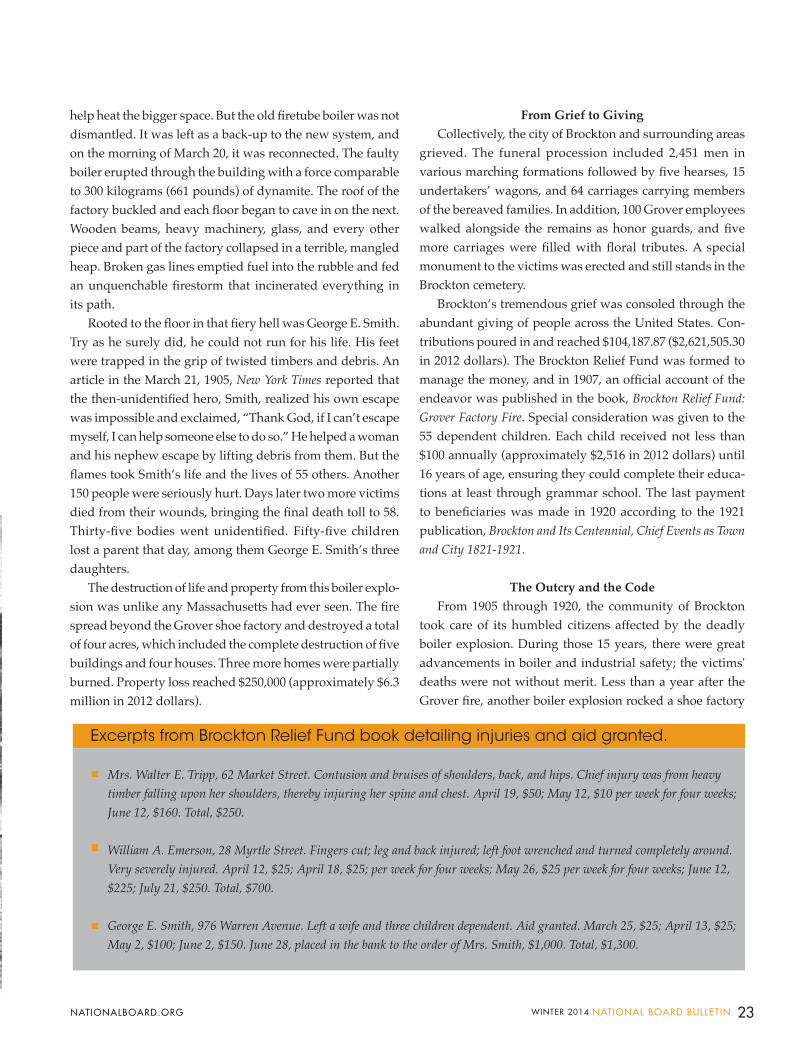
The destruction of life and property from this boiler explo-sion was unlike any Massachusetts had ever seen. The fire spread beyond the Grover shoe factory and destroyed a total of four acres, which included the complete destruction of five buildings and four houses. Three more homes were partially burned. Property loss reached $250,000 (approximately $6.3 million in 2012 dollars).
From Grief to GivingCollectively, the city of Brockton and surrounding areas
grieved. The funeral procession included 2,451 men in various marching formations followed by five hearses, 15 undertakers’ wagons, and 64 carriages carrying members of the bereaved families. In addition, 100 Grover employees walked alongside the remains as honor guards, and five more carriages were filled with floral tributes. A special monument to the victims was erected and still stands in the Brockton cemetery.
Brockton’s tremendous grief was consoled through the abundant giving of people across the United States. Con-tributions poured in and reached $104,187.87 ($2,621,505.30 in 2012 dollars). The Brockton Relief Fund was formed to manage the money, and in 1907, an official account of the endeavor was published in the book, Brockton Relief Fund: Grover Factory Fire. Special consideration was given to the 55 dependent children. Each child received not less than $100 annually (approximately $2,516 in 2012 dollars) until 16 years of age, ensuring they could complete their educa-tions at least through grammar school. The last payment to beneficiaries was made in 1920 according to the 1921 publication, Brockton and Its Centennial, Chief Events as Town and City 1821-1921.
The Outcry and the CodeFrom 1905 through 1920, the community of Brockton
took care of its humbled citizens affected by the deadly boiler explosion. During those 15 years, there were great advancements in boiler and industrial safety; the victims' deaths were not without merit. Less than a year after the Grover fire, another boiler explosion rocked a shoe factory
Mrs. Walter E. Tripp, 62 Market Street. Contusion and bruises of shoulders, back, and hips. Chief injury was from heavy timber falling upon her shoulders, thereby injuring her spine and chest. April 19, $50; May 12, $10 per week for four weeks; June 12, $160. Total, $250.
William A. Emerson, 28 Myrtle Street. Fingers cut; leg and back injured; left foot wrenched and turned completely around. Very severely injured. April 12, $25; April 18, $25; per week for four weeks; May 26, $25 per week for four weeks; June 12, $225; July 21, $250. Total, $700.
George E. Smith, 976 Warren Avenue. Left a wife and three children dependent. Aid granted. March 25, $25; April 13, $25; May 2, $100; June 2, $150. June 28, placed in the bank to the order of Mrs. Smith, $1,000. Total, $1,300.
Excerpts from Brockton Relief Fund book detailing injuries and aid granted.
23WINTER 2014 NATIONAL BOARD BULLETIN NATIONALBOARD.ORG
in the city of Lynn, Massachusetts. The two deadly boiler explosions stirred the governor of Massachusetts (who was from Brockton) to take serious action.
And so it was that in 1907 the Massachusetts Legislature created the nation's first Board of Boiler Rules within the Department of Public Safety. The members of the board represented a balance of interests: the Massachusetts Boiler Inspection Department, boiler users, boiler manufacturers, boiler insurers, and operating engineers. Together, these five representatives drafted the nation’s first set of boiler rules and regulations pertaining to the construction, operation, repair, and maintenance of boilers. The work in Massachusetts was the first of its kind and initiated a nationwide conversation about boiler codes and served as a framework for other states.
Recognizing the need for a national, uniform boiler code, boiler manufacturers and users reached out to ASME to develop a standard. The following feature, “100 Years: The ASME Boiler and Pressure Vessel Code,” written by ASME’s Gerry Eisenberg, continues the story of the Code’s develop-ment from then to now.
We remember Brockton and the Grover factory fire in such detail because the magnitude of that incident puts into perfect context the dire necessity of the ASME Boiler and Pressure Ves-sel Code in ensuring industrial safety. We cannot forget why such a code has existed for 100 years: those who witnessed the Grover fire and similar boiler explosions never wanted to see other communities suffer the same fate.
And so there was the outcry, and then there was the Code.
Sources used in research for this article:Derek A. Canavan, “The Grover Disaster: 100 Years.” National Board BULLETIN, fall 2005; Glenn Weaver and J. Bard McNulty, An Evolving Concern: Technology, Safety and The Hartford Steam Boiler Inspection and Insurance Company 1866-1991, HSB, 1991; Rev. Albert F. Pierce, D.D., Brockton Relief Fund: The Grover Factory Fire, Relief Fund Trustees, 1907; Elaine Allegrini, “Once Known as ‘Shoe City,’ Brockton Loses Its Last Factory.” The Dedham Transcript, (www.dailynewstranscript.com), March 2009; Jean Porrazzo, “March of Progress – The Rise and Decline of Shoe City, U.S.A.” The Dedham Transcript, (www.dailynewstranscript.com), September 2007; New York Times online public archives; Brockton, MA, website: www.brockton.ma.usa, About Brockton; ASME website: www.asme.org (Engineering History, The True Harnessing of Steam, and The History of ASME’s Boiler and Pressure Vessel Code).
BULLETIN photography courtesy of Brockton Historical Society Museum
24 NATIONAL BOARD BULLETIN WINTER 2014 NATIONALBOARD.ORG
COVER STORYBULLETIN
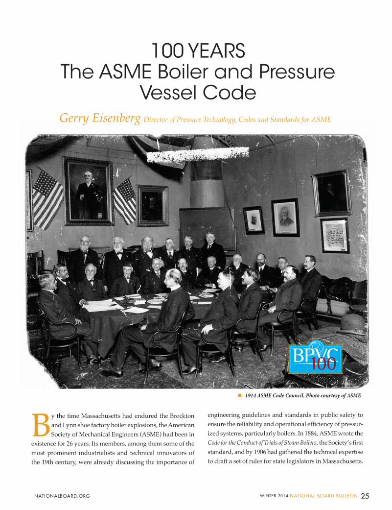
By the time Massachusetts had endured the Brockton and Lynn shoe factory boiler explosions, the American Society of Mechanical Engineers (ASME) had been in
existence for 26 years. Its members, among them some of the most prominent industrialists and technical innovators of the 19th century, were already discussing the importance of
engineering guidelines and standards in public safety to ensure the reliability and operational efficiency of pressur-ized systems, particularly boilers. In 1884, ASME wrote the Code for the Conduct of Trials of Steam Boilers, the Society’s first standard, and by 1906 had gathered the technical expertise to draft a set of rules for state legislators in Massachusetts.
100 YEARS The ASME Boiler and Pressure
Vessel Code Gerry Eisenberg, Director of Pressure Technology, Codes and Standards for ASME
BULLETIN photography courtesy of Brockton Historical Society Museum
1914 ASME Code Council. Photo courtesy of ASME
25WINTER 2014 NATIONAL BOARD BULLETIN NATIONALBOARD.ORG
While states saw the need to develop and adopt safety requirements for protection of the public, manufactur-ers quickly realized that a single set of requirements was more economical than multiple state rules, and insurance companies saw a reduction in the number of claims as a potential benefit of streamlining technical requirements. In 1911, the concept of developing a single technical code, us-ing a balanced committee of technical experts representing manufacturers, state authorities, and insurance companies, gained traction within the ASME Council and resulted in the formation of the ASME Boiler Code Committee. Leadership was provided by John A. Stevens, a member of a prominent family, consulting engineer for boiler users, and namesake of the Stevens Institute in New Jersey.
While ASME’s 1884 standard on conducting trials helped verify contractual claims of boiler performance by the manufacturer, members of the new committee felt there was a need to provide comprehensive criteria for the design, construction, inspection, and testing of boilers. As a result, ASME issued its first version of the ASME Boiler and Pressure Vessel Code (ASME Code) in the 1914 edition titled Rules for the Construction of Stationary Boilers and for Allow-able Working Pressures, which was published in 1915. It was instantly recognized as being the most robust and relevant standard of its kind, and helped to cement ASME’s reputa-tion for being able to bring diverse stakeholders together to solve complex challenges. To this day, the strength of the concept of reaching consensus through balanced committees and technical rigor still holds true.
Putting it into PracticeHaving a uniform standard in place was an important
step in helping to improve safety and reduce the likelihood of catastrophic events; however, oversight was needed in order to ensure the standard was being applied properly. In 1915, ASME established a certification system to verify equipment manufacturer compliance using third-party inspection. This provided jurisdictions and insurance com-panies (that regulated and insured equipment constructed to the Code) the ability to consistently evaluate a manu-facturer’s capability to build to the ASME Code through onsite inspections. Companies who passed this inspection were issued an ASME Code stamp that they could use as a symbol on their boiler nameplate, indicating their successful conformance to the Code.
Once a jurisdiction adopted the ASME Code, a boiler or pressure vessel with an ASME Code stamp that was
manufactured in one jurisdiction could be accepted for in-stallation and use in another jurisdiction. This greatly drove down costs for manufacturers by allowing them to achieve economies of scale, and also for businesses that purchased and operated equipment in multiple jurisdictions, by allow-ing them to maximize their purchasing power and reduce costs associated with regulatory compliance. With global-ization, the added value of standards as a tool for economic efficiency and trade – in addition to safety – is as important today as it was then.
Building a Comprehensive FrameworkWhile developing the Code was a historic accomplish-
ment, the state of the industry was continuously evolving. Manufacturers were eager to explore innovative processes, and regulators sought to share experiences in order to fulfill their mission in protecting the public. In 1916, a committee was established consisting of representatives appointed by state and local jurisdictions that had adopted or were plan-ning to adopt the ASME Code. This committee, called the Boiler and Pressure Vessel Conference Committee, provided a direct line of communication between regulators and the Code-writing committee. This program is still in place today.
As the responsibility to inspect manufacturers and fa-cilities fell on third parties in multiple jurisdictions, there was a need to provide uniformity in how inspections were conducted and how regulations were enforced. In 1919, the ASME Boiler Code Committee determined there was a need for an organization that could enforce uniform qualifica-tion of inspectors involved with the Code process, which was guided by the chief boiler inspectors of jurisdictions that had adopted the Code. This led to the formation of the National Board of Boiler and Pressure Vessel Inspectors in 1919, which quickly became a critical forum for addressing regulatory and inspection-related challenges and established the following programs:
• Qualification of all inspectors to a common set of requirements and issuing a National Board Com-mission to successful candidates.
• Authorization of ASME manufacturers to stamp a National Board registration number on boilers inspected by a National Board commissioned inspec-tor.
These programs gave the chief boiler inspectors of all participating states and cities the assurances they needed to allow a boiler to be installed for operation within their jurisdictions.
26 NATIONAL BOARD BULLETIN WINTER 2014 NATIONALBOARD.ORG
COVER STORYBULLETIN
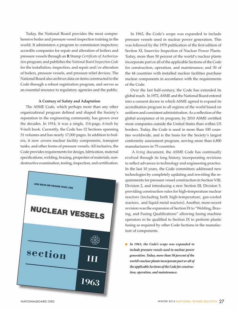
Today, the National Board provides the most compre-hensive boiler and pressure vessel inspection training in the world. It administers a program to commission inspectors; accredits companies for repair and alteration of boilers and pressure vessels through an R Stamp Certificate of Authoriza-tion program; and publishes the National Board Inspection Code for the installation, inspection, and repair and/or alteration of boilers, pressure vessels, and pressure relief devices. The National Board also archives data on items constructed to the Code through a robust registration program, and serves as an essential resource to regulatory agencies and the public.
A Century of Safety and AdaptationThe ASME Code, which perhaps more than any other
organizational program defined and shaped the Society’s reputation in the engineering community, has grown over the decades. In 1914, it was a single, 114-page, 6-inch by 9-inch book. Currently, the Code has 12 Sections spanning 31 volumes and has nearly 17,000 pages. In addition to boil-ers, it now covers nuclear facility components, transport tanks, and other forms of pressure vessels. All inclusive, the Code provides requirements for design, fabrication, material specifications, welding, brazing, properties of materials, non-destructive examination, testing, inspection, and certification.
In 1963, the Code’s scope was expanded to include pressure vessels used in nuclear power generation. This was followed by the 1970 publication of the first edition of Section XI, Inservice Inspection of Nuclear Power Plants. Today, more than 50 percent of the world’s nuclear plants incorporate part or all of the applicable Sections of the Code for construction, operation, and maintenance; and 30 of the 44 countries with installed nuclear facilities purchase nuclear components in accordance with the requirements of the Code.
Over the last half-century, the Code has extended its global reach. In 1972, ASME and the National Board entered into a consent decree in which ASME agreed to expand its accreditation program to all regions of the world based on uniform and consistent administration. As a reflection of the global acceptance of its program, by 2010 ASME certified more companies outside the United States than within US borders. Today, the Code is used in more than 100 coun-ties worldwide, and is the basis for the Society’s largest conformity assessment program, serving more than 6,800 manufacturers in 75 countries.
A living document, the ASME Code has continually evolved through its long history, incorporating revisions to reflect advances in technology and engineering practice. In the last 10 years, the Code committees addressed new technologies by completely updating and rewriting the re-quirements for pressure vessel construction in Section VIII, Division 2, and introducing a new Section III, Division 5, providing construction rules for high-temperature nuclear reactors (including both high-temperature, gas-cooled reactors, and liquid metal reactors). Another, more-recent revision was the expansion of Section IX to “Welding, Braz-ing, and Fusing Qualifications” allowing fusing machine operators to be qualified to Section IX to perform plastic fusing as required by other Code Sections in the manufac-ture of components.
In 1963, the Code’s scope was expanded to include pressure vessels used in nuclear power generation. Today, more than 50 percent of the world’s nuclear plants incorporate part or all of the applicable Sections of the Code for construc-tion, operation, and maintenance.
27WINTER 2014 NATIONAL BOARD BULLETIN NATIONALBOARD.ORG
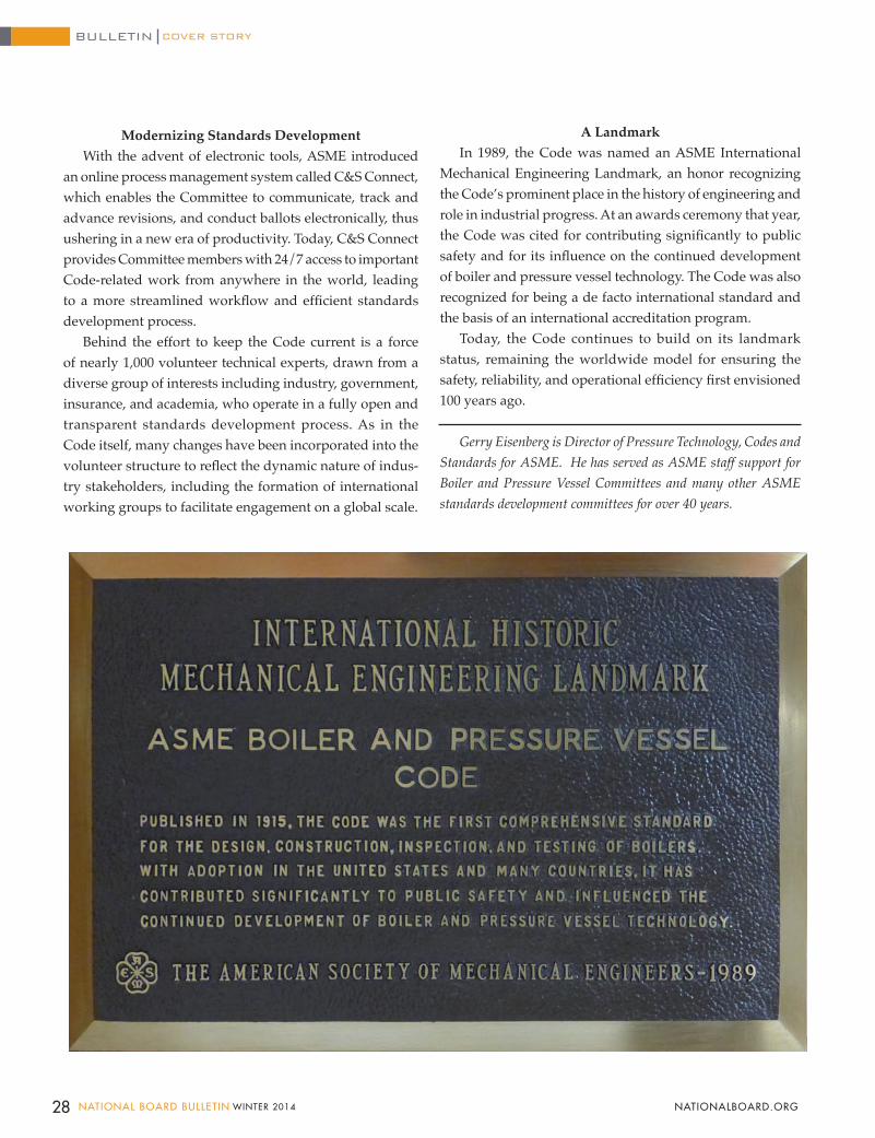
Modernizing Standards DevelopmentWith the advent of electronic tools, ASME introduced
an online process management system called C&S Connect, which enables the Committee to communicate, track and advance revisions, and conduct ballots electronically, thus ushering in a new era of productivity. Today, C&S Connect provides Committee members with 24/7 access to important Code-related work from anywhere in the world, leading to a more streamlined workflow and efficient standards development process.
Behind the effort to keep the Code current is a force of nearly 1,000 volunteer technical experts, drawn from a diverse group of interests including industry, government, insurance, and academia, who operate in a fully open and transparent standards development process. As in the Code itself, many changes have been incorporated into the volunteer structure to reflect the dynamic nature of indus-try stakeholders, including the formation of international working groups to facilitate engagement on a global scale.
A Landmark In 1989, the Code was named an ASME International
Mechanical Engineering Landmark, an honor recognizing the Code’s prominent place in the history of engineering and role in industrial progress. At an awards ceremony that year, the Code was cited for contributing significantly to public safety and for its influence on the continued development of boiler and pressure vessel technology. The Code was also recognized for being a de facto international standard and the basis of an international accreditation program.
Today, the Code continues to build on its landmark status, remaining the worldwide model for ensuring the safety, reliability, and operational efficiency first envisioned 100 years ago.
Gerry Eisenberg is Director of Pressure Technology, Codes and Standards for ASME. He has served as ASME staff support for Boiler and Pressure Vessel Committees and many other ASME standards development committees for over 40 years.
28 NATIONAL BOARD BULLETIN WINTER 2014 NATIONALBOARD.ORG
COVER STORYBULLETIN
Why do you think the ASME Code has endured successfully for 100 years?
For 100 years, the ASME Boiler and Pressure Code has held true to its mission of enhancing public safety through the talent and intellectual prowess of thousands of volunteers who utilize a process of strong principles based on open-ness, transparency, impartiality, consensus, and relevance. The Code Committee is a place where all perspectives and points of view are shared and debated. This hammering out of technical consensus through well-defined principles and procedures has contributed to the acceptance of the Code by industries and governments. Today, the ASME Code enhances the safety of people throughout the world.
Share a little insight about the people behind the Code.
The dedication and commitment of the people serving on the Code Committees have inspired me throughout my 40 years of service with ASME. It is truly amazing how much personal time is devoted to Code work, well above and beyond employer-supported time, and beyond what might be expected of even the most dedicated individuals. Besides the increasingly common act of joining teleconferences from airports, we have had volunteers calling in from family reunions, hospital beds, police stations, you name it. They have contributed at this level for decades, and I will always extend a special thanks to their spouses and families, whose patience and understanding allowed them to give of their time to the Code.
How do you think the Code will change in the future? The Code has basically stayed within its original objec-
tive of pressure retention and integrity for the past 100 years. An intriguing question is whether this will change; and if so, what forces would make such change reasonable? Would it be forces driven by the digital age and how future generations will access knowledge? Will there be a need to provide more than just pressure integrity requirements? How thoughts are shared or how Code content is delivered or accessed will follow what the times dictate, but the value of the Code as betterment to economies and peoples will remain. One thing is certain in my mind – the success of the Code will still be dependent on the commitment and intel-lectual prowess of those engaged in setting the standard, and on the process of consensus debate among different perspectives and interests.
What have been the most satisfying aspects of working with ASME and the Code?
The people and the impact. I have worked with the fin-est caliber of people. Regardless of geography or language, there is unity among those involved in the pressure equip-ment community (including nuclear power) and a common objective of quality products and public safety. Through the ASME Code, we have all had positive impact on the lives of many. To all of the past, current, and future Code contribu-tors – Happy 100th Anniversary.
Reflects on the Longevi ty and Success of the ASME Code
June Ling, Deputy Executive Director for ASME,
29WINTER 2014 NATIONAL BOARD BULLETIN NATIONALBOARD.ORG
30 NATIONAL BOARD BULLETIN WINTER 2014 NATIONALBOARD.ORG
Manufacturer’s Data Reports (MDR) for items constructed to the requirements of the
American Society of Mechanical Engineers Boiler and Pressure Vessel Code (ASME B&PVC) include Certificate of Compliance boxes. In these reports, to paraphrase the MDR, the manufacturer states its compliance with code requirements and the authorized inspector (AI) declares: “to the best of my knowledge and belief, the manufacturer has constructed the item in accordance with ASME B&PVC requirements.” This article focuses on AI qualifications, duties, and expectations for job performance that ensure the above declaration has purpose and meaning.
From the authorized inspection perspective, MDR certification statements can be thought of as the end point of a long and complex series of actions involving responsibilities and duties of the AI, with supporting roles by the AI supervisor and the authorized inspection agency (AIA), which provide a supportive working environment for the benefit of the AI.
QualificationThe National Board’s NB-263, Rules
for National Board Inservice and New Construction Commissioned Inspectors, and ASME’s QAI-1, Qualifications for Authorized Inspection, describe AI, AI supervisor, and AIA qualification requirements and duties. In regards to the AI, terms referenced in these documents include: qualification, knowledge, demonstrated ability, and expertise. NB-263 and ASME QAI-1 are intended for the development and assignment of qualified inspection professionals.
The ASME B&PVC Sections (e.g., Sections I, IV, and VIII) define the
requirements for actions by the AI. Terms used in these Sections include performing, making, witnessing, and verifying.
AIA quality system programs provide the link between ASME QAI-1, NB-263, and the ASME B&PVC Section requirements by defining which activities are within their program scope, how activities are controlled, and which verification methods are to be utilized.
PerformanceAll of these terms ultimately define the
role of the AI. The AI is at the fabricating shops and field sites as required to fulfill these duties. The AI may be assigned full-time in a manufacturer’s shop, or be available as needed. The AI is responsible for inspecting items during the construction phase and certifying the manufacturer’s and AI’s involvement in the inspection of an item.
An AI must utilize effective inspection practices. These generally can be divided into three categories: design and job package review, in-process inspection, and test witnessing/final inspection.
Design and Job Package Review A design and job package review
includes a review of design calculations, material lists, drawings, implementation procedures and instructions, and process control documents, such as travelers or process sheets. Unique controls established by the manufacturer’s documented quality control system can also be verified at this time.
Code design requirements can be reviewed. These include the selected code edition and addenda, use of correct code formulas, establishment of design or
maximum allowable working pressure, determination of design or required thickness compared to material ordered thicknesses, and permitted materials and any limitations on their use.
Code special process requirements, such as welding, nondestructive examination, and heat treatment, can be reviewed. Are special process procedures required to be qualified by the manufacturer or demonstrated to the satisfaction of the AI? Pressure testing controls can be reviewed based on the proposed scope of work. Will the proposed fabrication sequence allow or limit the ability of the AI to witness or verify operations?
The AI needs to be as informed as the manufacturer so meaningful inspection can be achieved. To that purpose, a thorough review of the proposed work is essential. As work progresses, revisions to design or job package documents need to be reviewed by the AI in order to stay current with the proposed work. A comprehensive review early on may identify areas requiring correction, and it is much easier to correct problems while work is still in the planning stages.
At the design and job package review stage, the AI can establish inspection points. The exact meaning of an inspection point varies depending on whom you talk to. Hold points, witness points, surveillance points, and review points are terms commonly used. In any event, the selected term or terms must be understood by the manufacturer’s personnel and the AI. Typically, the manufacturer’s quality program will define the terms used in order to provide a mutual understanding of their meaning.
Authorized Inspector Involvement What’s the Point?
FEATUREBULLETIN
31WINTER 2014 NATIONAL BOARD BULLETIN NATIONALBOARD.ORG
In-Process InspectionThe importance of in-process
inspection cannot be overemphasized. While records review has real value, it’s very important that the AI actually see a portion of work in progress in order to give validity to those records. For example, the AI may review a manufacturer’s sign-off on a traveler for the fit and tack weld of two butt-welded pressure parts. But if the AI hasn’t previously witnessed the performance of selected fit-up inspections by the manufacturer’s personnel, there is no way for the AI to determine if they are actually looking at things such as weld bevel, root gap, alignment, cleanliness, and filler material selection in order to meet code, drawing, and welding procedure requirements. Are the manufacturer’s personnel inspecting tack welds for defects such as cracks, and if defective, are they removed? However, if the AI continuously witnesses random fit-up activities, a determination can be made regarding the knowledge of the person performing the evaluation and whether requirements are being met.
The AI involvement with fabrication activities is relatively low compared to the overall level of fabrication activity. If the AI adopts an effective inspection technique and periodically performs random inspections, confidence in the quality of the work rises and records review has more meaning.
Test Witnessing/Final InspectionAI witnessing of final pressure tests is
mandatory. The AI has the duty to verify that the pressure gage range is within code-permitted limits and that pressure gage calibration requirements have been met as described in the manufacturer’s quality control program. Are filling, venting, and pressurization requirements met? Has a careful inspection been made by the manufacturer and the AI
for leakage at welds and regions of high stress?
At the time of the pressure test, final inspection is usually performed. Identification markings and dimensional requirements are verified. Inspections of external material and weld surfaces are performed. Internal material and weld surfaces should be inspected prior to the pressure test, but if that is impractical, can be conducted after the pressure test. Final inspection also determines whether the finished item and the drawing referenced on the MDR and the required calculations represent the “as-built” condition.
Final inspection also includes a determination as to whether documents and records required by the code and the quality control program are complete, legible, reviewed, and approved as required.
ConclusionHow much AI involvement is required
in inspections? That’s a question for the ages. The adequacy of AI involvement relies on the complexity of the work performed. AI supervisor audits can evaluate the adequacy and depth of AI involvement. Additionally, ASME joint reviews, while primarily determining manufacturer compliance, include an assessment of the adequacy of AI activities. When deficiencies are identified during audits or joint reviews, or worse, when product compliance is below acceptable levels or inservice failures result, the question of AI inspection adequacy must be addressed. Is this the kind of deficiency or failure that could have been prevented had adequate inspection methods been used by the AI during manufacture?
Sadly, a trend has developed in recent years decreasing the amount of time permitted an AI to perform in-process inspections, in favor of records reviews.
While there are no hard requirements defining the amount of inspection time required, the ASME QAI-1 and NB-263 documents referenced earlier and their use of terms such as knowledge, demonstrated ability, expertise, and witnessing, would lead us to conclude these standards seek to establish the AI as an inspector and not just a record reviewer. After all, the job title is Authorized Inspector.
So, what’s the point of having authorized inspector involvement?
Boilers and pressure vessels constructed to the requirements of the ASME code rely on an authorized inspector to provide oversight in matters concerning code compliance. Oversight also includes a determination that the manufacturer is working in accordance with its quality control program, including a description of organizational structure, design, materials, examination and inspection, correction of nonconformities, welding, nondestructive examination, heat treatment, calibration of measurement and test equipment, and records.
The AI needs to be vigilant while performing inspections. A manufacturer’s product today could be very different than, say, six months from now. Factors may include a change in components, changes in management or ownership, loss of skilled personnel, adjustments of staffing levels, new subcontracted service providers, and aggressive competition. The AI cannot become complacent by assuming that the quality level of manufactured items remains constant. Only continuous and adequate inspection by the AI can validate code and quality control program compliance.
When the AI certifies the MDR, “. . .to the best of my knowledge and belief that the item is in compliance. . .” the assumption on the part of the public at large is that the AI has given his best. The public should demand nothing less.
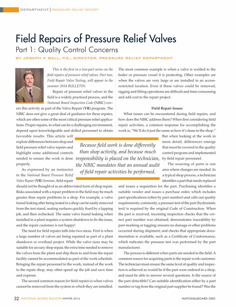
Field Repairs of Pressure Relief ValvesPart 1: Quality Control ConcernsBY JOSEPH F. BALL, P.E., DIRECTOR, PRESSURE RELIEF DEPARTMENT
This is the first in a two-part series on the field repairs of pressure relief valves. Part two, Field Repair Valve Testing, will appear in the summer 2014 BULLETIN.
Repair of pressure relief valves in the field is a widely practiced process, and the National Board Inspection Code (NBIC) cov-
ers this activity as part of the Valve Repair (VR) program. The NBIC does not give a great deal of guidance for these repairs, which are often some of the most critical pressure relief applica-tions. Proper repairs, in what can be a challenging environment, depend upon knowledgeable and skilled personnel to obtain favorable results. This article will explore differences between shop and field pressure relief valve repairs and highlight some additional controls needed to ensure the work is done properly.
As expressed by an instructor in the National Board Pressure Relief Valve Repair (VR) Seminar, field repair should not be thought of as an abbreviated form of shop repair. Risks associated with a repair problem in the field may be much greater than repair problems in a shop. For example, a valve found leaking after being tested in a shop can be easily removed from the test stand, seating surfaces quickly fixed by a lapping job, and then rechecked. The same valve found leaking when installed in a plant requires a system shutdown to fix the issue, and the repair customer is not happy!
The need for field repairs falls into two areas. First is when a large number of valves are being repaired as part of a plant shutdown or overhaul project. While the valve sizes may be suitable for an easy shop repair, the extra time needed to remove the valves from the plant and ship them to and from the repair facility cannot be accommodated as part of the work schedule. Bringing the repair personnel to the work, instead of the work to the repair shop, may often speed up the job and save time and expense.
The second common reason for field repairs is when valves cannot be removed from the system in which they are installed.
PRESSURE RELIEF REPORTDEPARTMENT
The most common example is when a valve is welded to the boiler or pressure vessel it is protecting. Other examples are when the valves are very large or are installed in an access-restricted location. Even if these valves could be removed, rigging and lifting operations are difficult and time-consuming and add cost to the repair project.
Field Repair IssuesWhat issues can be encountered during field repairs, and
how does the NBIC address them? When first considering field repair activities, a common response for accomplishing the work is, “We’ll do it just the same as how it’s done in the shop.”
But when looking at the work in more detail, differences emerge that must be covered in the quality control program and implemented by field repair personnel.
The sourcing of parts is one area where changes are needed. In a typical shop process, a technician identifies a part that needs replaced
and issues a requisition for the part. Purchasing identifies a suitable vendor and issues a purchase order, which includes part specifications (often by part number) and calls out quality requirements; commonly, a pressure test of the part (hydrostatic test) is required by the original Code of Construction. When the part is received, incoming inspection checks that the cor-rect part number was obtained; demonstrates traceability by part-marking or tagging; ensures no damage or other problems occurred during shipment; and checks that appropriate docu-mentation is available, such as a Certificate of Conformance, which indicates the pressure test was performed by the part manufacturer.
The process is different when parts are needed in the field. A common source for acquiring parts is the repair work customer. The technician must ensure the same level of quality and inspec-tion is achieved as would be if the part were ordered in a shop, and must be able to answer several questions. Is the source of the part detectible? Can suitable identification either by a part number or tag from the original part supplier be found? Was the
Because field work is done differently than shop activity, and because much
responsibility is placed on the technician, the NBIC mandates that an annual audit
of field repair activities be performed.
32 NATIONAL BOARD BULLETIN WINTER 2014 NATIONALBOARD.ORG
part pressure-tested as required? The organization applying the VR repair symbol must ensure all NBIC requirements have been met, even if the customer supplies the part. If the parts have been in the customer’s storeroom for a long time, documentation may be difficult to obtain.
Even if the part is ordered in the same way using the shop requisition process, parts are often “drop shipped” to the worksite and the receiving process is carried out by the technician, who must have access to the purchasing information to know what inspections are needed. Often, documentation is not supplied with the part and is instead sent separately to the shop where it cannot be checked by the technician receiving the part.
A second activity that is different for field repairs is the need to use the customer’s measurement equipment, such as needing to obtain a pressure measurement from the system where the valve is installed. This may be for the “live” setting of the valve where it is actually opened using system pres-sure. A pressure reading is also needed when a lift-assist test method is used. Often the repair organization cannot install its own pressure-measuring equipment due to lack of a suit-able installation location. If a pressure tap is present in steam systems, it may not be suitably protected from the effects of high temperature. The VR stamp holder’s quality program will specify a calibration frequency for measurement and test equipment, and their test stand layout will indicate the required level of accuracy.
When a repair organization cannot use its own equip-ment, the same level of control needed for their own pres-sure gage must be adapted to the instrumentation supplied by the customer. Checks would include a recent calibration date, documented evidence of the last calibration performed, traceability to a national standard, and a suitable accuracy specification. An additional concern would be determining if the gage was suitable to be used as a test gage instead of being used for system pressure readings. Pressure-measuring equipment used for line-pressure measurement often in-cludes a damping device to smooth out pressure pulsations. These gages are not suitable for pressure relief valve perfor-mance testing because they do not respond quickly enough. Similar issues can be encountered when the customer’s machining equipment is utilized and their linear-measuring equipment is used to confirm measurements during these operations.
Another difference with field repairs is that the customer’s repair personnel may help with the work. This gives the re-
pair technician extra assistance, but also recognizes that there may be contracts in place mandating certain types of work be performed by plant personnel. It should be recognized that plant personnel are more familiar with their plant’s systems, and their expertise in establishing the safety of those systems will always be an asset to workplace safety. The NBIC permits owner-user personnel to help with repairs, but the quality system must address this activity. In particular, the VR stamp holder must have the freedom to assign or remove personnel as needed and is responsible for the training involved in the repairs. Training can be specific to the quality-related tasks personnel are assisting with. Assistance with the installation or removal of valves from a system is beyond the scope of the repair program and would, therefore, not be part of the VR repair process.
Often field repairs are performed by a single technician, per-haps with assistance from the customer. In the shop environment, workflow structure is thus: the repair technician performs the work, followed by a quality inspection by another individual who checks for workmanship and documentation. Final tests are often witnessed by a second person to verify test data. In the field, the person who performs the work also manages the quality control element. Because field work is done differently than shop activity, and because much responsibility is placed on the technician, the NBIC mandates that an annual audit of field repair activities be per-formed. The audit must include witnessing the valve performance tests; therefore, the auditor must go to the field site and observe jobs in action to ensure all quality elements are accomplished. It is not enough to just check a repair traveler, and the auditor gets to experience the real working conditions that the technicians put up with every day!
While the NBIC does not mandate any particular level of training or competence for specific job positions, it should be acknowledged that field repair technicians bear a large amount of responsibility. Hopefully they are selected based on their consider-able experience and demonstrated ability.
Field technicians are the complete “face” of the company to the customer and must often work long hours in demanding conditions. The top of the boiler is either hot or cold, and experienced workers will tell you it’s rarely the perfect working condition. That’s why strict attention to the special quality control requirements needed in those conditions is critical to ensure repaired pressure relief valves function safely.
NBIC References, 2013 EditionQuality Manual Requirements: NBIC Part 3, Paragraph 1.7.5.4 r)Field Repair Requirements: NBIC Part 3, Supplement 7, Paragraphs S7.7 through S7.9
33WINTER 2014 NATIONAL BOARD BULLETIN NATIONALBOARD.ORG
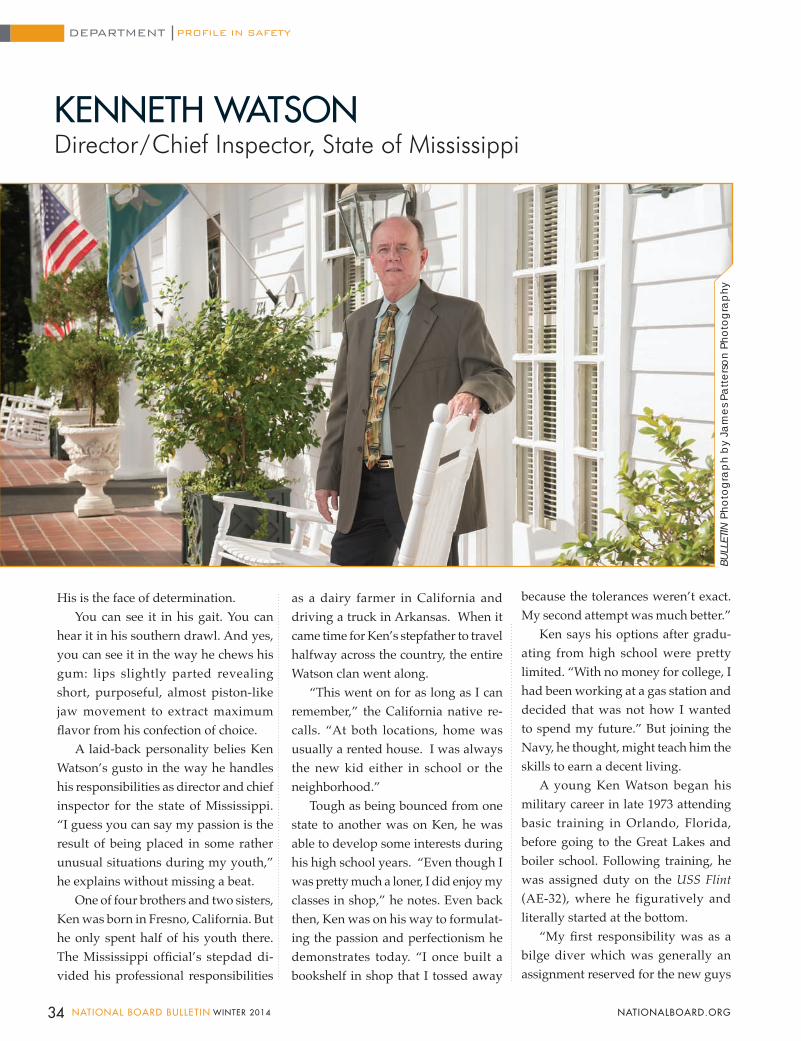
because the tolerances weren’t exact. My second attempt was much better.”
Ken says his options after gradu-ating from high school were pretty limited. “With no money for college, I had been working at a gas station and decided that was not how I wanted to spend my future.” But joining the Navy, he thought, might teach him the skills to earn a decent living.
A young Ken Watson began his military career in late 1973 attending basic training in Orlando, Florida, before going to the Great Lakes and boiler school. Following training, he was assigned duty on the USS Flint (AE-32), where he figuratively and literally started at the bottom.
“My first responsibility was as a bilge diver which was generally an assignment reserved for the new guys
KENNETH WATSONDirector/Chief Inspector, State of Mississippi
His is the face of determination.You can see it in his gait. You can
hear it in his southern drawl. And yes, you can see it in the way he chews his gum: lips slightly parted revealing short, purposeful, almost piston-like jaw movement to extract maximum flavor from his confection of choice.
A laid-back personality belies Ken Watson’s gusto in the way he handles his responsibilities as director and chief inspector for the state of Mississippi. “I guess you can say my passion is the result of being placed in some rather unusual situations during my youth,” he explains without missing a beat.
One of four brothers and two sisters, Ken was born in Fresno, California. But he only spent half of his youth there. The Mississippi official’s stepdad di-vided his professional responsibilities
as a dairy farmer in California and driving a truck in Arkansas. When it came time for Ken’s stepfather to travel halfway across the country, the entire Watson clan went along.
“This went on for as long as I can remember,” the California native re-calls. “At both locations, home was usually a rented house. I was always the new kid either in school or the neighborhood.”
Tough as being bounced from one state to another was on Ken, he was able to develop some interests during his high school years. “Even though I was pretty much a loner, I did enjoy my classes in shop,” he notes. Even back then, Ken was on his way to formulat-ing the passion and perfectionism he demonstrates today. “I once built a bookshelf in shop that I tossed away
34 NATIONAL BOARD BULLETIN WINTER 2014 NATIONALBOARD.ORG
BULL
ETIN
Pho
togr
ap
h b
y Ja
mes
Pat
ters
on P
hoto
grap
hy
PROFILE IN SAFETYDEPARTMENT
and those unfortunate to receive military punishment.”
Thinking about ways to get out of bilge duty, Ken had an epiphany. “I had to learn how to do something others couldn’t do,” he explains with a smile. That kind of determination would later define the passion of the Mississippi official.
For three months, he used the bilge experience to learn the ship’s piping sys-tem. And because an astute Ken Watson also learned how to light off a boiler, he was promoted to fireman and conse-quently sent to boiler controls school. “Because the unit was fully automatic, I returned from school only to learn that I was the only sailor aboard ship who knew how to repair the controls,” he chuckles.
Now armed with boiler experience, Ken lost no time returning to Arkansas following his discharge. His first job: water treatment operator for Arkansas Power & Light. “Again, I was starting at the bottom, but there was nowhere to go but up,” he observes philosophically.
Ken was promoted to auxiliary op-erator and finally to boiler operator. But working a rotating shift prompted him to consider ways of improving himself professionally. “I briefly attended night school when it suddenly occurred to me that the money I was making as an operator was pretty comparable to what college graduates were making at the time.” School was no longer an option.
In 1979, Ken visited with then-Ar-kansas chief John Crosby who inquired about the former’s interest in possibly becoming a state boiler inspector. He politely declined. Unbowed by Ken’s disinterest, the chief gave Ken a 1977 edition of the National Board Inspection
Code to read during his operator shifts.Now having some familiarity with
the code, Ken eventually agreed to at least take the commission exam. “I remember Mr. Crosby calling me with the news I had passed,” he smiles.
As time at Arkansas Power & Light progressed, the Mississippi official was determined to escape from the time limitations of shift work. He joined the state of Arkansas as deputy boiler inspector in March of 1980. “I really took a hit on the salary difference,” he laments, “but I figured the rewards would be important long term.” And he didn’t have to wait long.
In August of that year, Ken was dispatched to pick up then-National Board Executive Director Sam Har-rison from the airport to attend the annual state fish fry. Because Ken’s car lacked air-conditioning, a profusely sweating executive director arrived at the event and made it his first point of business to make sure Crosby gave his new employee a raise.
“It couldn’t have come at a better time,” the National Board member laughs. “I had just gotten married and we had a new baby.”
The meager salary notwithstand-ing, Ken was compelled to stay with the state until his daughter finished school. (The similarity of his own upbringing and being constantly up-rooted was not lost on him.)
During his tenure with Arkansas, Ken held varying posts, from deputy to chief inspector, for five chief inspectors before he decided in 2003 to retire and become, as he calls it, “a gentleman farmer.”
In 2004, after months of watch-ing soap operas and waiting for the
mailman, Ken received a telephone call from then-Mississippi Chief Henry Mc-Ewen who was searching for help in his jurisdiction. The California native started in January of 2005, again as a deputy in-spector. He was appointed chief inspector in March of 2007 when McEwen retired.
Since taking the helm in Mississippi, the National Board member today over-sees an administrative assistant, three data control clerks, and four deputy inspectors. He cites as accomplishments a doubling of staff salaries, improved relationships with the governor’s office, and a proactive advisory committee he personally selected.
Recently, after being single for 20 years, Ken ran into an old friend whom he admits had been “the apple of my eye” for some time. Although Lynn and Ken stood parted only by the Arkansas/Mississippi state line, the two spent weekends together – so many weekends, it should be noted – that Ken popped the question at a “surprise engagement party.” The soon-to-be-bride said yes and Ken and Lynn married last September.
Although his route to the top has been circuitous at best, Ken says living and working close to his beloved Arkansas and having a loving family are his re-ward for having the grit to continually persevere.
Ken says being shy and a loner while growing up in Arkansas and California fostered a strong sense of determination and independence that has served him well.
Quoting military novelist Tom Clancy, Ken concludes: “There are two kinds of people: the ones who need to be told and the ones who figure it out all by themselves.”
Indeed.
35WINTER 2014 NATIONAL BOARD BULLETIN NATIONALBOARD.ORG
Training Continues to Grow in 2014BY KIMBERLY MILLER, MANAGER OF TRAINING
The National Board training department is gearing up for another busy year of training in 2014. Currently there are 23 classes scheduled for a total of 34 weeks of training, most being conducted on our campus in Columbus, Ohio.
Of course, commission training is a high priority, with 22 of the 34 weeks dedicated to training students to become inservice and new construction commissioned inspectors.
The New Construction Commission and Authorized Inspector Course (A) is on the calendar seven times in 2014: February, April, June, July, September, October, and December. Students spend nine days in the classroom and inspection room learning the discipline of becoming an authorized inspector; the 85-question, two-part examination is then administered on day 10. As always, this course is in high demand so enrolling early is encouraged.
The Inservice Commission Course (IC) has four dates set for 2014: January, April/May, August, and November. Students attending this training spend nine days learning ASME and NBIC code requirements in the classroom, which is complemented with time in our hands-on inspection room. Just like in the New Construction course, day 10 is assessment day when students may sit for the final examination.
An important note about the two commission courses: while originally designed for the student wishing to obtain a National Board Commission, this training also meets the requirements of individuals seeking the new Pressure Equipment Inspector certification. For more information on this new program please visit Commissions & Certifications/Pressure Equipment Inspectors at www.nationalboard.org.
Also on the calendar for 2014 is a menu of nuclear training which includes two Authorized Nuclear Inspector Course (N) dates, one Authorized Nuclear Inservice Inspector Course (I), and one Authorized Nuclear Inspector Supervisor Course (NS). Students attending any of the nuclear training courses in 2014 will be the first through completely revised nuclear training programs. The first of the new courses to debut will be the redesigned and updated N course, with a class scheduled for March and a second in August. The I and NS courses will follow with dates in September and November, respectively.
The remaining training calendar consists of two Authorized Inspector Supervisor (B) class dates: one in March and the second in September; two Pressure Relief Valve Repair (VR) seminars in Columbus (March and June); and two Boiler and Pressure Vessel Repair (RO) seminars in Columbus (February and May). Both the VR and RO repair seminars will be conducted in Seattle, Washington, in September/October, with the exact dates to be released on the National Board website in early spring.
TRAINING MATTERSDEPARTMENT
For students unable to travel to our classroom training but still wanting to take some type of National Board training, you’re in luck. There are more online courses being offered today than ever before in the history of National Board training. With 18 different titles in our menu of online training, students have a variety of courses to choose from. Additional titles are set to be released in 2014 as well, including nuclear continuing education courses for the I and C endorsed inspectors, a nuclear code reading course, and an advanced mathematics for code calculations course.
It is definitely another busy year.
Author’s Note: Did you know examination questions may be submitted to the National Board for use in any commission or endorsement exam? To do so visit www.nationalboard.org and click on Training/Submit an Exam Question.
36 NATIONAL BOARD BULLETIN WINTER 2014 NATIONALBOARD.ORG
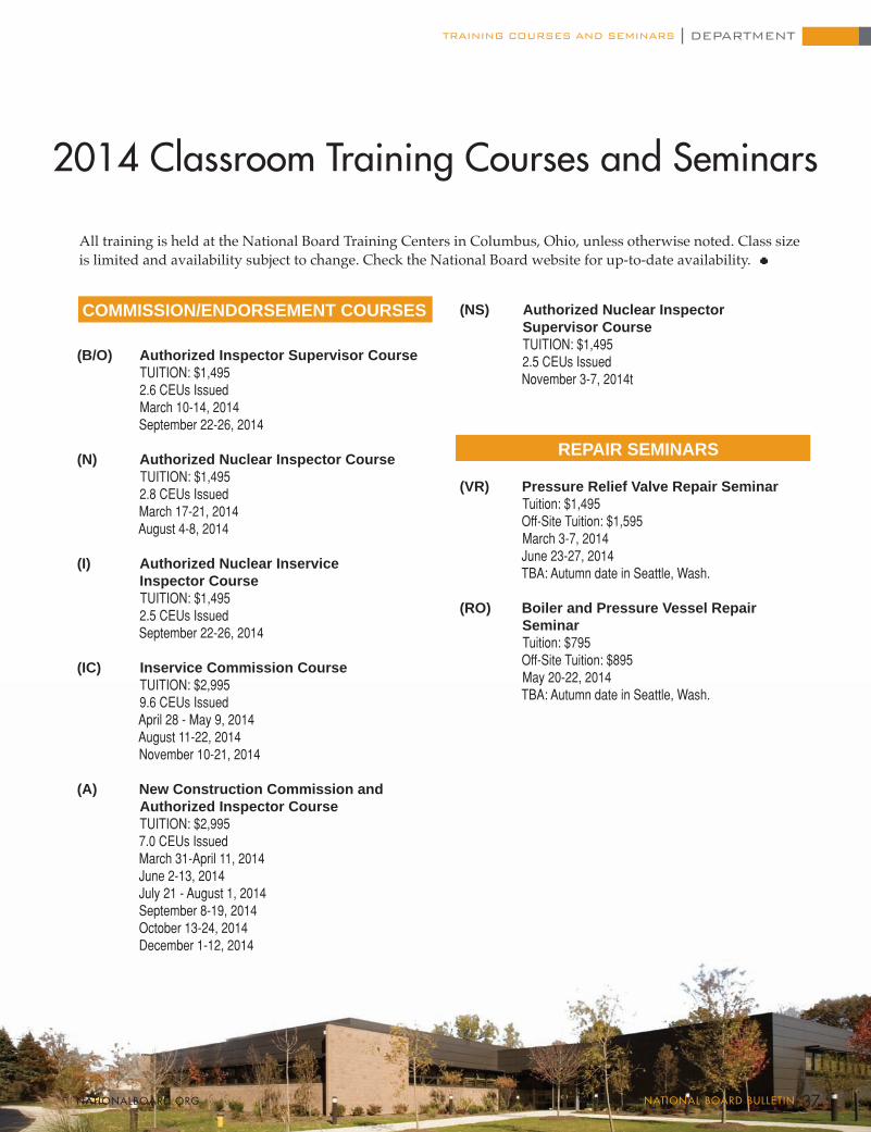
TRAINING COURSES AND SEMINARS DEPARTMENT
REPAIR SEMINARS
COMMISSION/ENDORSEMENT COURSES
2014 Classroom Training Courses and Seminars
(B/O) Authorized Inspector Supervisor Course TUITION: $1,495 2.6 CEUs Issued
March 10-14, 2014 September 22-26, 2014
(N) Authorized Nuclear Inspector Course TUITION: $1,495 2.8 CEUs Issued
March 17-21, 2014 August 4-8, 2014
(I) Authorized Nuclear Inservice Inspector Course TUITION: $1,495
2.5 CEUs Issued September 22-26, 2014
(IC) Inservice Commission Course TUITION: $2,995
9.6 CEUs Issued April 28 - May 9, 2014 August 11-22, 2014 November 10-21, 2014
(A) New Construction Commission and Authorized Inspector Course TUITION: $2,995 7.0 CEUs Issued March 31-April 11, 2014 June 2-13, 2014 July 21 - August 1, 2014 September 8-19, 2014 October 13-24, 2014 December 1-12, 2014
(VR) Pressure Relief Valve Repair Seminar Tuition: $1,495 Off-Site Tuition: $1,595 March 3-7, 2014 June 23-27, 2014 TBA: Autumn date in Seattle, Wash.
(RO) Boiler and Pressure Vessel Repair Seminar Tuition: $795 Off-Site Tuition: $895 May 20-22, 2014 TBA: Autumn date in Seattle, Wash.
All training is held at the National Board Training Centers in Columbus, Ohio, unless otherwise noted. Class size is limited and availability subject to change. Check the National Board website for up-to-date availability.
(NS) Authorized Nuclear Inspector Supervisor Course TUITION: $1,495
2.5 CEUs Issued November 3-7, 2014t
37WINTER 2014 NATIONAL BOARD BULLETIN NATIONALBOARD.ORG
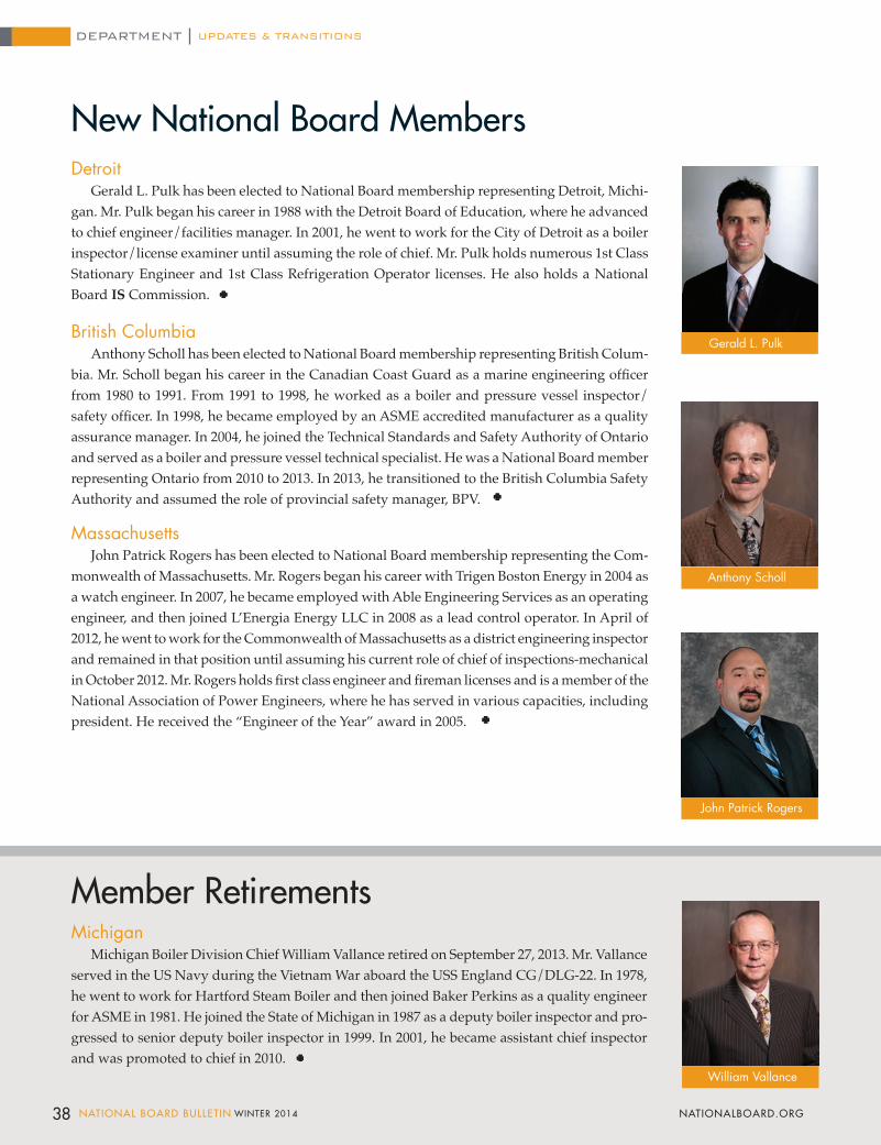
38 NATIONAL BOARD BULLETIN WINTER 2014 NATIONALBOARD.ORG
DetroitGerald L. Pulk has been elected to National Board membership representing Detroit, Michi-
gan. Mr. Pulk began his career in 1988 with the Detroit Board of Education, where he advanced to chief engineer/facilities manager. In 2001, he went to work for the City of Detroit as a boiler inspector/license examiner until assuming the role of chief. Mr. Pulk holds numerous 1st Class Stationary Engineer and 1st Class Refrigeration Operator licenses. He also holds a National Board IS Commission.
British Columbia
Anthony Scholl has been elected to National Board membership representing British Colum-bia. Mr. Scholl began his career in the Canadian Coast Guard as a marine engineering officer from 1980 to 1991. From 1991 to 1998, he worked as a boiler and pressure vessel inspector/safety officer. In 1998, he became employed by an ASME accredited manufacturer as a quality assurance manager. In 2004, he joined the Technical Standards and Safety Authority of Ontario and served as a boiler and pressure vessel technical specialist. He was a National Board member representing Ontario from 2010 to 2013. In 2013, he transitioned to the British Columbia Safety Authority and assumed the role of provincial safety manager, BPV.
MassachusettsJohn Patrick Rogers has been elected to National Board membership representing the Com-
monwealth of Massachusetts. Mr. Rogers began his career with Trigen Boston Energy in 2004 as a watch engineer. In 2007, he became employed with Able Engineering Services as an operating engineer, and then joined L’Energia Energy LLC in 2008 as a lead control operator. In April of 2012, he went to work for the Commonwealth of Massachusetts as a district engineering inspector and remained in that position until assuming his current role of chief of inspections-mechanical in October 2012. Mr. Rogers holds first class engineer and fireman licenses and is a member of the National Association of Power Engineers, where he has served in various capacities, including president. He received the “Engineer of the Year” award in 2005.
New National Board Members
Gerald L. Pulk
Anthony Scholl
John Patrick Rogers
William Vallance
Michigan Michigan Boiler Division Chief William Vallance retired on September 27, 2013. Mr. Vallance
served in the US Navy during the Vietnam War aboard the USS England CG/DLG-22. In 1978, he went to work for Hartford Steam Boiler and then joined Baker Perkins as a quality engineer for ASME in 1981. He joined the State of Michigan in 1987 as a deputy boiler inspector and pro-gressed to senior deputy boiler inspector in 1999. In 2001, he became assistant chief inspector and was promoted to chief in 2010.
Member Retirements
UPDATES & TRANSITIONSDEPARTMENT
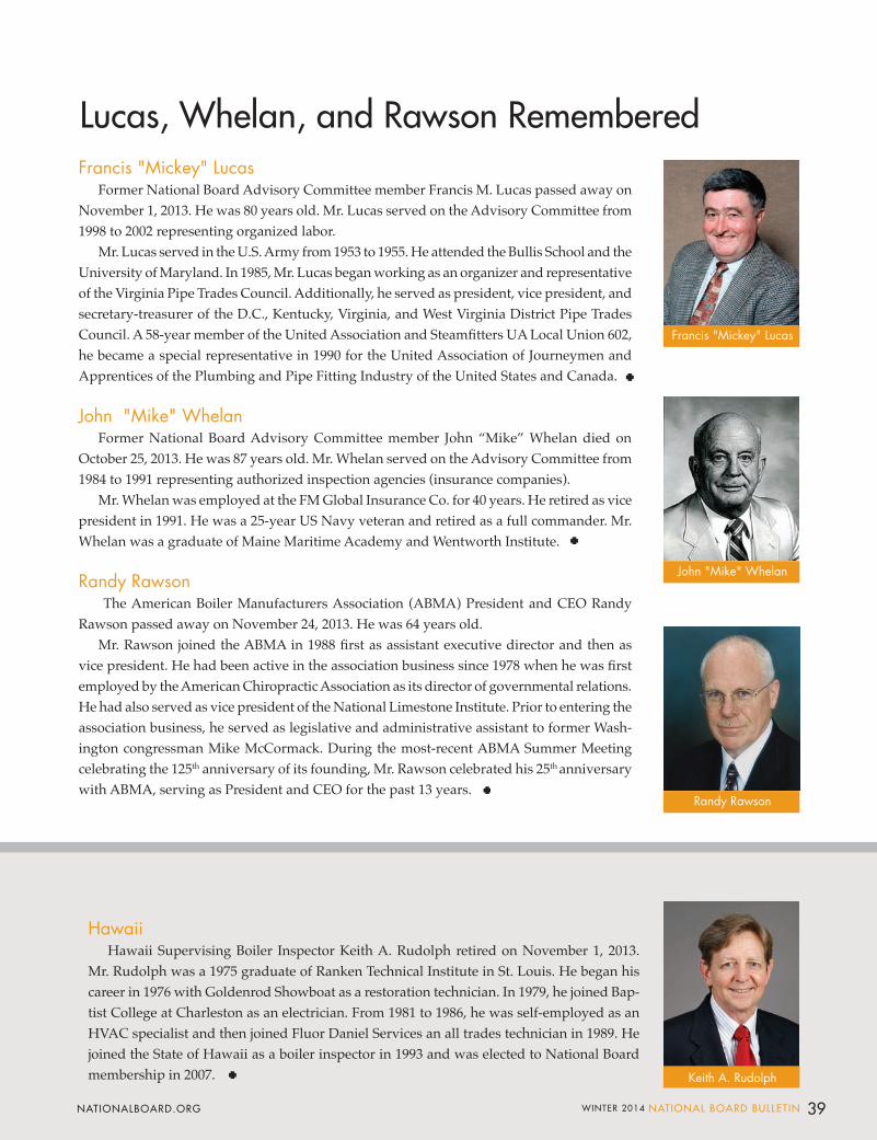
Francis "Mickey" LucasFormer National Board Advisory Committee member Francis M. Lucas passed away on
November 1, 2013. He was 80 years old. Mr. Lucas served on the Advisory Committee from 1998 to 2002 representing organized labor.
Mr. Lucas served in the U.S. Army from 1953 to 1955. He attended the Bullis School and the University of Maryland. In 1985, Mr. Lucas began working as an organizer and representative of the Virginia Pipe Trades Council. Additionally, he served as president, vice president, and secretary-treasurer of the D.C., Kentucky, Virginia, and West Virginia District Pipe Trades Council. A 58-year member of the United Association and Steamfitters UA Local Union 602, he became a special representative in 1990 for the United Association of Journeymen and Apprentices of the Plumbing and Pipe Fitting Industry of the United States and Canada.
John "Mike" Whelan
Former National Board Advisory Committee member John “Mike” Whelan died on October 25, 2013. He was 87 years old. Mr. Whelan served on the Advisory Committee from 1984 to 1991 representing authorized inspection agencies (insurance companies).
Mr. Whelan was employed at the FM Global Insurance Co. for 40 years. He retired as vice president in 1991. He was a 25-year US Navy veteran and retired as a full commander. Mr. Whelan was a graduate of Maine Maritime Academy and Wentworth Institute.
Randy Rawson The American Boiler Manufacturers Association (ABMA) President and CEO Randy
Rawson passed away on November 24, 2013. He was 64 years old. Mr. Rawson joined the ABMA in 1988 first as assistant executive director and then as
vice president. He had been active in the association business since 1978 when he was first employed by the American Chiropractic Association as its director of governmental relations. He had also served as vice president of the National Limestone Institute. Prior to entering the association business, he served as legislative and administrative assistant to former Wash-ington congressman Mike McCormack. During the most-recent ABMA Summer Meeting celebrating the 125th anniversary of its founding, Mr. Rawson celebrated his 25th anniversary with ABMA, serving as President and CEO for the past 13 years.
39WINTER 2014 NATIONAL BOARD BULLETIN NATIONALBOARD.ORG
Francis "Mickey" Lucas
John "Mike" Whelan
Lucas, Whelan, and Rawson Remembered
Randy Rawson
Keith A. Rudolph
HawaiiHawaii Supervising Boiler Inspector Keith A. Rudolph retired on November 1, 2013.
Mr. Rudolph was a 1975 graduate of Ranken Technical Institute in St. Louis. He began his career in 1976 with Goldenrod Showboat as a restoration technician. In 1979, he joined Bap-tist College at Charleston as an electrician. From 1981 to 1986, he was self-employed as an HVAC specialist and then joined Fluor Daniel Services an all trades technician in 1989. He joined the State of Hawaii as a boiler inspector in 1993 and was elected to National Board membership in 2007.
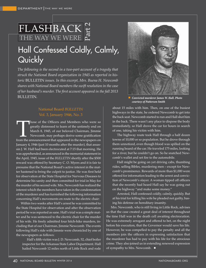
Those of the Officers and Members who were so greatly distressed to learn of the untimely end on March 8, 1945, of our beloved Chairman, Jimmie Newcomb, may perhaps derive some gratification
from the announcement that appeared in the newspapers on January 4, 1946 (just 10 months after the murder), that assas-sin J. W. Hall had been electrocuted at 7:15 that morning. He was apprehended, as announced in the memorial statement in the April, 1945, issue of the BULLETIN shortly after the $500 reward was offered by Secretary C. O. Myers and it is fair to presume that the National Board’s active interest in the mat-ter hastened to bring the culprit to justice. He was first held for observation at the State Hospital for Nervous Diseases to determine his sanity and then committed for trial in May for the murder of his second wife. Mrs. Newcomb has realized the interest which the members have taken in the condemnation of the murderer and has furnished the following information concerning Hall’s movements en route to the electric chair:
Within two weeks after Hall’s arrest he was committed to the State Hospital for observation and after the observation period he was reported as sane. Hall’s trial was a simple mat-ter and he was sentenced to the electric chair for the murder of his wife. He freely admitted four hitch-hike murders, in-cluding that of our Chairman, Jimmie Newcomb. The events following Hall’s ride with Jimmie were chronicled by one of the newspapers as follows:
Hall’s fifth victim was J. D. Newcomb, 52, chief boiler inspector for the Arkansas State Labor Department. Hall hailed Newcomb 12 miles north of Little Rock and rode
THE WAY WE WEREFLASHBACK
Part
2
Hall Confessed Coldly, Calmly,QuicklyThe following is the second in a two-part account of a tragedy that struck the National Board organization in 1945 as reported in his-toric BULLETIN issues. In this excerpt, Mrs. Buena H. Newcomb shares with National Board members the swift resolution in the case of her husband’s murder. The first account appeared in the fall 2013 BULLETIN.
about 15 miles with him. Then, on one of the busiest highways in the state, he ordered Newcomb to get into the back seat. Newcomb started to run and Hall shot him in the back. There wasn’t any place to dispose the body immediately, so Hall drove the car for hours in search of one, taking his victim with him.
The highway route took Hall through a half dozen towns of 10,000 or so population. But he drove through them unnoticed, even though blood was spilled on the running board of the car. He traveled 175 miles, looking for a river, but he couldn’t go on. So he snatched New-comb’s wallet and set fire to the automobile.
Hall might be going on yet driving cabs, thumbing rides, selling Bibles, murdering men – except for New-comb’s prominence. Rewards of more than $1,000 were offered for information leading to the arrest and convic-tion of Newcomb’s slayer. A woman tipped off officers that she recently had heard Hall say he was going out on the highway “and make some money.”
Arrested, Hall confessed coldly, calmly, quickly. But at his trial for killing his wife he pleaded not guilty, bas-ing his defense on hereditary insanity.
Mrs. Newcomb, who is still living in Little Rock, advises us that the case created a great deal of interest throughout the time Hall was in the death cell awaiting electrocution. He was extremely arrogant and offered to bet, on the night before his execution, that the Governor would save his life. However, he was compelled to pay the penalty and all the members join the officers in expressing satisfaction that the murderer has had to pay with his life for the atrocious crime. They also joined us in extending renewed expression of sympathy to Mrs. Newcomb.
National Board BULLETIN Vol. 3, January 1946, No. 3
Convicted murderer James W. Hall. Photo courtesy of Patterson Smith
40 NATIONAL BOARD BULLETIN WINTER 2014 NATIONALBOARD.ORG
THE WAY WE WEREDEPARTMENT
Learn more about the National Board Pressure Relief Valve Repair (VR) Program at www.nationalboard.org
Industry professionals have answers. Help train others by asking the tough questions.
The National Board Training Department encourages industry participation in the development of exam questions. So tell us what you know, or rather, what you think students should know to become knowledgeable inspectors.
Questions can be submitted for the following course exams: • New Construction (A)• Authorized Inspector Supervisor (B)• Authorized Nuclear Inservice (I) • Inservice Commission (IC)• Authorized Nuclear Inspector (N)• Authorized Nuclear Inspector Supervisor (NS)• Review Team Leader (RTL)
Submit an exam question by visiting www.nationalboard.org. Click the Training tab and choose “Submit an Exam Question” from the dropdown box.

Headquarters, Training and Conference Center,and Inspection Training Center1055 Crupper AvenueColumbus, Ohio 43229-1183Phone 614.888.8320Fax 614.888.0750
Testing Laboratory7437 Pingue DriveWorthington, Ohio 43085-1715Phone 614.888.8320Fax 614.848.3474
national board.orgVisit for Bulletin Archives


