Email: [email protected]The NAOS visible wave front sensor Philippe Feautrier a , Pierre Kern a , Reinhold Dorn c , Gérard Rousset b , Patrick Rabou a , Sylvain Laurent a , Jean-Louis Lizon c , Eric Stadler a , Yves Magnard a , Olivier Rondeaux b , Mathieu Cochard a , Didier Rabaud b , Alain Delboulbe a , Pascal Puget a , Norbert Hubin c , a Laboratoire d’Astrophysique de l’Observatoire de Grenoble, BP 53, 38041 Grenoble Cedex 9, France b ONERA, BP 72, 92322 Chatillon Cedex, France c ESO, Karl Schwartzschild Strasse 2, D-85748 Garching bei Munchen, Germany ABSTRACT This paper describes the Visible Wave Front Sensor (visible WFS) for the VLT Nasmith Adaptive Optics system (NAOS). This Shack-Hartman-based wave front sensor instrument includes within a continuous flow liquid nitrogen cryostat: - a low noise fast readout CCD camera controlled by the ESO new generation CCD controller FIERA. The readout noise of this system is 3 e- at 50 kilopixel/sec/port, and is only limited by the CCD intrinsic noise. FIERA features remotely controlled readout modes with optional binning, windowing and flexible integration time. - two remotely exchangeable micro-lens arrays focusing the analyzed wave front directly on the CCD sensitive surface. The wave front sensor includes also its own atmospheric dispersion compensator. Due to the continuous rotation of the NAOS adapter, the mechanical stiffness of the visible wave front sensor must be very high not to disturb the loop operation (no more than 0.1 µm of lenslet array displacement compared to the CCD location over a 30° rotation angle of the instrument). The following simulations and tests are described: - simulation results providing an estimation of the NAOS maximum operating magnitude - camera optimization - mechanical stiffness measurements 1. INTRODUCTION NAOS, described in Ref. 1 and Ref. 2, is the adaptive optics system of the ESO Very Large Telescope. Installed at the Nasmyth focus of the VLT, NAOS is the AO system for CONICA (see Ref. 3), the science infrared camera. NAOS will provide diffraction limited images in the 1-5 µm wavelengths range. NAOS has been designed and manufactured by a French consortium (ONERA, LAOG, Observatoire de Paris). The deformable mirror with 185 useful actuators compensates the atmospheric disturbance measured by two Shack Hartman wave-front sensors (WFS), one covering the visible wavelengths and the other covering the infrared. This paper describes the visible wave front sensor. NAOS is mounted on the telescope adapter rotator and rotates with the telescope field rotation. Therefore, the structure stiffness of the whole instrument is a big issue for the final performances of the instrument. The opto-mechanical path of the wave-front sensing channel requires a special care to avoid flexure contribution to the measurements. Such contribution will degrade the image quality. The sensitivity of the whole NAOS instrument is highly dependent of the wave-front sensor performances. The visible WFS for NAOS uses a 128x128 pixels low noise CCD fabricated by EEV with 16 output ports to allow a high frame rate (500 frames/sec) and low noise (3 e - ). After a brief description of the visible wave-front sensor in the first section, a second section describes the low noise camera used for this wave-front sensor. We give first the CCD characteristics, then we describe the CCD controller (FIERA) developed by the ESO detector group. The readout modes of the camera are explained. Finally, we give a summary of the performed tests. The last section describes the wave-front sensor itself with its main characteristics. We report the tests performed on the instrument with emphasis given on the stiffness tests. 2. VISIBLE WAVEFRONT SENSOR PRESENTATION 1. Overview The design of this Shack Hartman-based wave-front sensor has been optimized according to system simulations for the whole NAOS instrument (see Ref. 2). These simulations drived the design choice of the micro-lens arrays, and the readout mode configuration of the detector (binning, pixel and frame rates, windowing) depending on the seeing conditions, the
Philippe Feautriera, Pierre Kerna, Reinhold Dornc, Gérard Roussetb , Patrick Raboua, Sylvain Laurenta,Jean-Louis Lizonc, Eric Stadlera, Yves Magnarda, Olivier Rondeauxb, Mathieu Cocharda,
Didier Rabaudb, Alain Delboulbea, Pascal Pugeta, Norbert Hubinc,aLaboratoire d’Astrophysique de l’Observatoire de Grenoble, BP 53, 38041 Grenoble Cedex 9, France
bONERA, BP 72, 92322 Chatillon Cedex, France cESO, Karl Schwartzschild Strasse 2, D-85748 Garching bei Munchen, Germany
ABSTRACTThis paper describes the Visible Wave Front Sensor (visible WFS) for the VLT Nasmith Adaptive Optics system (NAOS).This Shack-Hartman-based wave front sensor instrument includes within a continuous flow liquid nitrogen cryostat:- a low noise fast readout CCD camera controlled by the ESO new generation CCD controller FIERA. The readout noise
of this system is 3 e- at 50 kilopixel/sec/port, and is only limited by the CCD intrinsic noise. FIERA features remotelycontrolled readout modes with optional binning, windowing and flexible integration time.
- two remotely exchangeable micro-lens arrays focusing the analyzed wave front directly on the CCD sensitive surface.The wave front sensor includes also its own atmospheric dispersion compensator. Due to the continuous rotation of theNAOS adapter, the mechanical stiffness of the visible wave front sensor must be very high not to disturb the loop operation(no more than 0.1 µm of lenslet array displacement compared to the CCD location over a 30° rotation angle of theinstrument).The following simulations and tests are described:- simulation results providing an estimation of the NAOS maximum operating magnitude- camera optimization- mechanical stiffness measurements
1. INTRODUCTION
NAOS, described in Ref. 1 and Ref. 2, is the adaptive optics system of the ESO Very Large Telescope. Installed at theNasmyth focus of the VLT, NAOS is the AO system for CONICA (see Ref. 3), the science infrared camera. NAOS willprovide diffraction limited images in the 1-5 µm wavelengths range. NAOS has been designed and manufactured by aFrench consortium (ONERA, LAOG, Observatoire de Paris).The deformable mirror with 185 useful actuators compensates the atmospheric disturbance measured by two Shack Hartmanwave-front sensors (WFS), one covering the visible wavelengths and the other covering the infrared. This paper describesthe visible wave front sensor. NAOS is mounted on the telescope adapter rotator and rotates with the telescope fieldrotation. Therefore, the structure stiffness of the whole instrument is a big issue for the final performances of the instrument.The opto-mechanical path of the wave-front sensing channel requires a special care to avoid flexure contribution to themeasurements. Such contribution will degrade the image quality.The sensitivity of the whole NAOS instrument is highly dependent of the wave-front sensor performances. The visible WFSfor NAOS uses a 128x128 pixels low noise CCD fabricated by EEV with 16 output ports to allow a high frame rate (500frames/sec) and low noise (3 e-).
After a brief description of the visible wave-front sensor in the first section, a second section describes the low noise cameraused for this wave-front sensor. We give first the CCD characteristics, then we describe the CCD controller (FIERA)developed by the ESO detector group. The readout modes of the camera are explained. Finally, we give a summary of theperformed tests.The last section describes the wave-front sensor itself with its main characteristics. We report the tests performed on theinstrument with emphasis given on the stiffness tests.
The design of this Shack Hartman-based wave-front sensor has been optimized according to system simulations for thewhole NAOS instrument (see Ref. 2). These simulations drived the design choice of the micro-lens arrays, and the readoutmode configuration of the detector (binning, pixel and frame rates, windowing) depending on the seeing conditions, the
magnitude of the reference star and the readout noise of the detector. The "windowing" function is used to definerectangular windows containing the useful pixels, lines outside this windows are skipped to gain time during the CCDreadout. This allows to decrease the pixel rate (and also the readout noise) for a given frame rate.
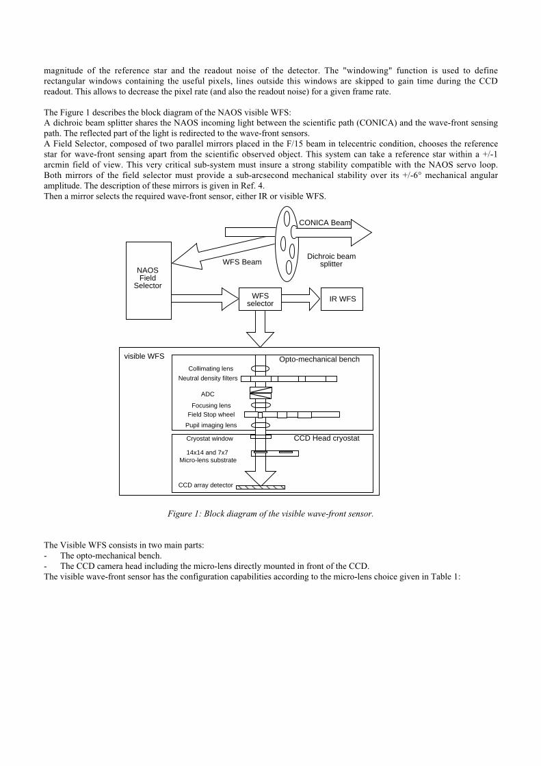
The Figure 1 describes the block diagram of the NAOS visible WFS:A dichroic beam splitter shares the NAOS incoming light between the scientific path (CONICA) and the wave-front sensingpath. The reflected part of the light is redirected to the wave-front sensors.A Field Selector, composed of two parallel mirrors placed in the F/15 beam in telecentric condition, chooses the referencestar for wave-front sensing apart from the scientific observed object. This system can take a reference star within a +/-1arcmin field of view. This very critical sub-system must insure a strong stability compatible with the NAOS servo loop.Both mirrors of the field selector must provide a sub-arcsecond mechanical stability over its +/-6° mechanical angularamplitude. The description of these mirrors is given in Ref. 4.Then a mirror selects the required wave-front sensor, either IR or visible WFS.
Figure 1: Block diagram of the visible wave-front sensor.
The Visible WFS consists in two main parts:- The opto-mechanical bench.- The CCD camera head including the micro-lens directly mounted in front of the CCD.The visible wave-front sensor has the configuration capabilities according to the micro-lens choice given in Table 1:
CONICA Beam
NAOS Field
SelectorWFS
selectorIR WFS
visible WFS Opto-mechanical bench
CCD Head cryostat
CCD array detector
14x14 and 7x7 Micro-lens substrate
Cryostat window
Collimating lens
Neutral density filters
ADC
Focusing lens
Pupil imaging lens
Field Stop wheel
Dichroic beam splitterWFS Beam
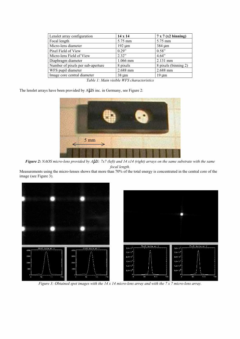
Lenslet array configuration 14 x 14 7 x 7 (x2 binning)Focal length 5.75 mm 5.75 mmMicro-lens diameter 192 µm 384 µmPixel Field of View 0.29” 0.58”Micro-lens Field of View 2.32” 4.64”Diaphragm diameter 1.066 mm 2.131 mmNumber of pixels per sub-aperture 8 pixels 8 pixels (binning 2)WFS pupil diameter 2.688 mm 2.688 mmImage core central diameter 38 µm 19 µm
Table 1: Main visible WFS characteristics
The lenslet arrays have been provided by AµS inc. in Germany, see Figure 2:
Figure 2: NAOS micro-lens provided by AµS: 7x7 (left) and 14 x14 (right) arrays on the same substrate with the samefocal length.
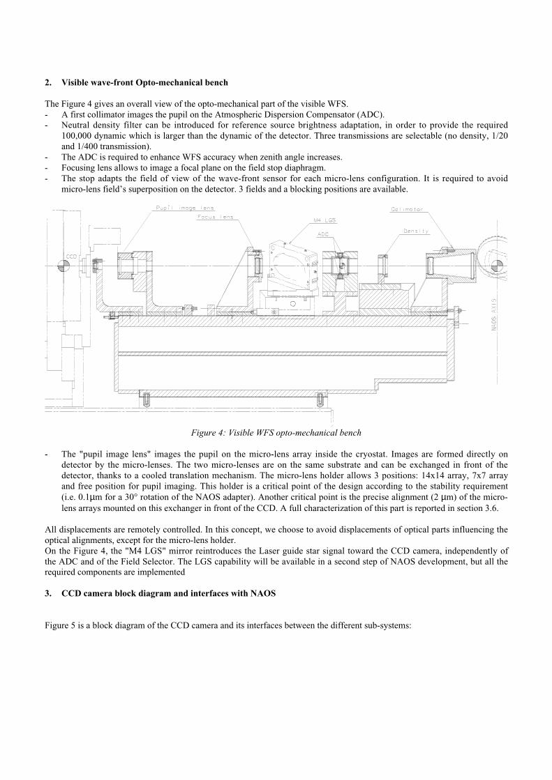
Measurements using the micro-lenses shows that more than 70% of the total energy is concentrated in the central core of theimage (see Figure 3).
Figure 3: Obtained spot images with the 14 x 14 micro-lens array and with the 7 x 7 micro-lens array.
5 mm
2. Visible wave-front Opto-mechanical bench
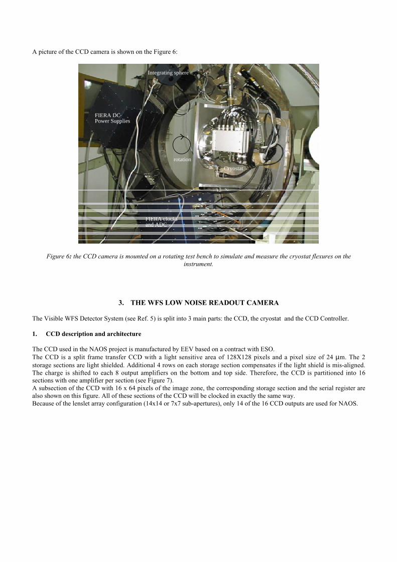
The Figure 4 gives an overall view of the opto-mechanical part of the visible WFS.- A first collimator images the pupil on the Atmospheric Dispersion Compensator (ADC).- Neutral density filter can be introduced for reference source brightness adaptation, in order to provide the required
100,000 dynamic which is larger than the dynamic of the detector. Three transmissions are selectable (no density, 1/20and 1/400 transmission).
- The ADC is required to enhance WFS accuracy when zenith angle increases.- Focusing lens allows to image a focal plane on the field stop diaphragm.- The stop adapts the field of view of the wave-front sensor for each micro-lens configuration. It is required to avoid
micro-lens field’s superposition on the detector. 3 fields and a blocking positions are available.
Figure 4: Visible WFS opto-mechanical bench
- The "pupil image lens" images the pupil on the micro-lens array inside the cryostat. Images are formed directly ondetector by the micro-lenses. The two micro-lenses are on the same substrate and can be exchanged in front of thedetector, thanks to a cooled translation mechanism. The micro-lens holder allows 3 positions: 14x14 array, 7x7 arrayand free position for pupil imaging. This holder is a critical point of the design according to the stability requirement(i.e. 0.1µm for a 30° rotation of the NAOS adapter). Another critical point is the precise alignment (2 µm) of the micro-lens arrays mounted on this exchanger in front of the CCD. A full characterization of this part is reported in section 3.6.
All displacements are remotely controlled. In this concept, we choose to avoid displacements of optical parts influencing theoptical alignments, except for the micro-lens holder.On the Figure 4, the "M4 LGS" mirror reintroduces the Laser guide star signal toward the CCD camera, independently ofthe ADC and of the Field Selector. The LGS capability will be available in a second step of NAOS development, but all therequired components are implemented
3. CCD camera block diagram and interfaces with NAOS
Figure 5 is a block diagram of the CCD camera and its interfaces between the different sub-systems:
• The Real time Computer (RTC) calculates from the CCD camera data the correction to be applied to the deformablemirror.• The NAOS workstation and Instrument Control Local Control Unit (IC LCU) are under the responsibility of the NAOSconsortium.The IC LCU commands all the motors of NAOS and in particular the motors of the visible wave-front sensor opto-mechanical components.• The FIERA optical detector system, developed by ESO, is divided into 3 main parts:
1) The SPARC-LCU is a Local Control Unit under Unix operating system. It uses a SPARC CPU and 2 DSPs(TMS320C40) which captures the data and send them to the RTC in real time and to the workstation in near-real time,controls the detector head electronics (readout mode selection, exposure control, CCD safety). The SPARC-LCU isconnected to the detector head electronics via an optical fiber link. It also provides a network interface. A fast videointerface limited to 1 m length is used to transfer all video data to the Real time Computer. The SPARC LCU rack will beintegrated in the NAOS electronics cabinet on the Nasmyth platform.2) The FIERA detector head electronics.It is composed of two metallic EMI/EMC shielded boxes. In one box is placed the DC power supplies, in the other is placedthe detector head electronics SRAM sequencer, the 16 video channels (Correlated Double Samplers, 16 bit A/D 1 MHzconverters). The FIERA detector head electronics is mounted directly on the NAOS adapter. The 2 racks are cooled with aclosed liquid cooling system, as any electronics rack mounted on the telescope area, to avoid air convection.3) The CCD is cooled with a liquid nitrogen continuous flow cryostat. Four Pre-Amplifier boxes with 4 channels perpreamplifier are attached to the cryostat to minimize the distance between the CCD chip and the preamplifier.The detector head electronics of the FIERA-CCD controller is connected to the cryostat via clock, bias, and video cables.The cryostat and the detector head electronics are mounted on the NAOS instrument.The cryostat temperature is controlled with a special rack named PULPO which measures in addition the cryostat vacuum.
Figure 5: Visible WFS Detector System and CCD camera block diagram
Real TimeComputer
LCU
NAOSWorkstation
ContinuousFlow
Cryostat
CCD
FIERASPARC
LCU
FIERAdetector head
electronics
microlensarrays,
optics controlIC-
LCU
16 bit Video data,3 bit control
Local Network
A picture of the CCD camera is shown on the Figure 6:
FIERA clocksand ADC
FIERA DCPower Supplies
Integrating sphere
Cryostat
rotation
Figure 6: the CCD camera is mounted on a rotating test bench to simulate and measure the cryostat flexures on theinstrument.
3. THE WFS LOW NOISE READOUT CAMERA
The Visible WFS Detector System (see Ref. 5) is split into 3 main parts: the CCD, the cryostat and the CCD Controller.
1. CCD description and architecture
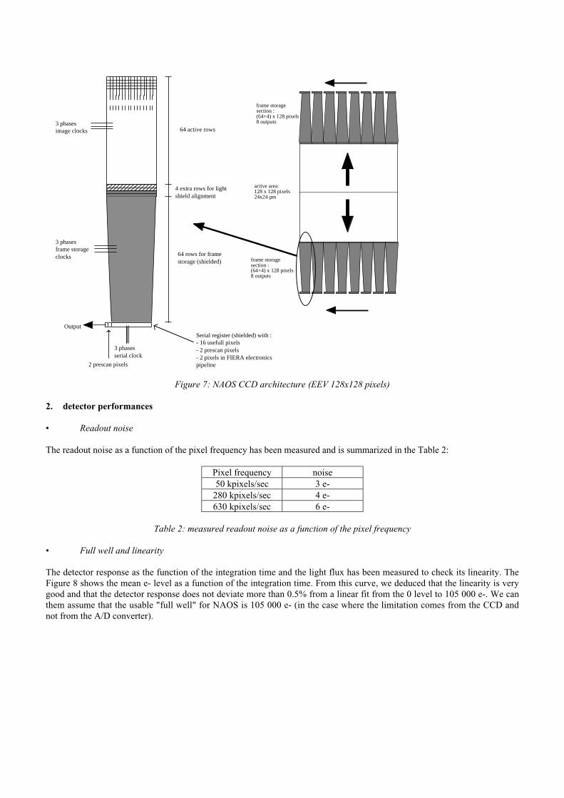
The CCD used in the NAOS project is manufactured by EEV based on a contract with ESO.The CCD is a split frame transfer CCD with a light sensitive area of 128X128 pixels and a pixel size of 24 µm. The 2storage sections are light shielded. Additional 4 rows on each storage section compensates if the light shield is mis-aligned.The charge is shifted to each 8 output amplifiers on the bottom and top side. Therefore, the CCD is partitioned into 16sections with one amplifier per section (see Figure 7).A subsection of the CCD with 16 x 64 pixels of the image zone, the corresponding storage section and the serial register arealso shown on this figure. All of these sections of the CCD will be clocked in exactly the same way.Because of the lenslet array configuration (14x14 or 7x7 sub-apertures), only 14 of the 16 CCD outputs are used for NAOS.
3 phasesimage clocks
3 phasesframe storage clocks
Output
2 prescan pixels
3 phasesserial clock
Serial register (shielded) with :- 16 usefull pixels- 2 prescan pixels- 2 pixels in FIERA electronics pipeline
64 active rows
4 extra rows for lightshield alignment
64 rows for frame storage (shielded)
active area:128 x 128 pixels24x24 µm
frame storagesection :(64+4) x 128 pixels8 outputs
frame storagesection :(64+4) x 128 pixels8 outputs
The readout noise as a function of the pixel frequency has been measured and is summarized in the Table 2:
Pixel frequency noise50 kpixels/sec 3 e-
280 kpixels/sec 4 e-630 kpixels/sec 6 e-
Table 2: measured readout noise as a function of the pixel frequency
• Full well and linearity
The detector response as the function of the integration time and the light flux has been measured to check its linearity. TheFigure 8 shows the mean e- level as a function of the integration time. From this curve, we deduced that the linearity is verygood and that the detector response does not deviate more than 0.5% from a linear fit from the 0 level to 105 000 e-. We canthem assume that the usable "full well" for NAOS is 105 000 e- (in the case where the limitation comes from the CCD andnot from the A/D converter).
0
20000
40000
60000
80000
100000
120000
0 0.2 0.4 0.6 0.8 1 1.2
Mean level (e-)linear fit (e-)
Mea
n le
vel
(e-)
Int. Time (sec)
Figure 8: Mean detector response as a function of the integration time
• Quantum efficiency (QE)
Like the readout noise, the quantum efficiency is of great importance for the performances of the wave-front sensor. TheQ.E. has not been measured yet, the Figure 9 shows the guaranteed minimum QE by EEV. It will be measured very soon.
0
20
40
60
80
100
300 400 500 600 700 800 900 1000
QE
(%
)
λ (nm)
Figure 9: minimum QE specified to the CCD manufacturer EEV
3. Cryostat cooling
At the chosen operating temperature, the dark current should add a negligible contribution to the readout noise (<10% of thereadout noise). A sufficiently low temperature has to be reached to attain that goal. Therefore the CCD is cooled at atemperature of 190 K using the standard ESO continuous flow cryostat.The liquid nitrogen is stored in a 100 liters external tank and not inside the cryostat. It has to be exchanged only every 2weeks, this simplifies the cryostat operation on the telescope.
4. The FIERA CCD Controller
ESO has built an universal CCD controller able to drive a variety of "new generation" CCDs. This original system is calledFIERA (Fast Imager Electronic Readout Assembly).
The requirements for the FIERA CCD Controller are briefly summarized for the NAOS system:
• System noise negligible compared to the readout noise of the CCD amplifier.• x2 and x4 binning capability, windowing capability• Up to 2 Mpixel/sec operation• 16 simultaneous video outputs can be managed. On NAOS, we use 14 ADC 16 bits/1 MHz• Cross-talk between channels of the CCD controller must be negligible - less than 1 bit or less than CCD readout
noise.
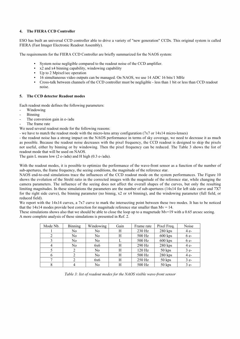
5. The CCD detector Readout modes
Each readout mode defines the following parameters:- Windowing- Binning- The conversion gain in e-/adu- The frame rateWe need several readout mode for the following reasons:- we have to match the readout mode with the micro-lens array configuration (7x7 or 14x14 micro-lenses)- the readout noise has a strong impact on the NAOS performance in terms of sky coverage, we need to decrease it as muchas possible. Because the readout noise decreases with the pixel frequency, the CCD readout is designed to skip the pixelsnot useful, either by binning or by windowing. Then the pixel frequency can be reduced. The Table 3 shows the list ofreadout mode that will be used on NAOS.The gain L means low (2 e-/adu) and H high (0.3 e-/adu).
With the readout modes, it is possible to optimize the performance of the wave-front sensor as a function of the number ofsub-apertures, the frame frequency, the seeing conditions, the magnitude of the reference star.NAOS end-to-end simulations trace the influences of the CCD readout mode on the system performances. The Figure 10shows the evolution of the Strehl ratio in the corrected images with the magnitude of the reference star, while changing thecamera parameters. The influence of the seeing does not affect the overall shapes of the curves, but only the resultinglimiting magnitudes. In these simulations the parameters are the number of sub-apertures (14x14 for left side curve and 7X7for the right side curve), the binning parameter (no binnig, x2 or x4 binning), and the windowing parameter (full field, orreduced field).We report with the 14x14 curves, a 7x7 curve to mark the intersecting point between these two modes. It has to be noticedthat the 14x14 modes provide best correction for magnitude reference star smaller than Mv = 14.These simulations shows also that we should be able to close the loop up to a magnetude Mv=19 with a 0.65 arcsec seeing.A more complete analysis of these simulations is presented in Ref. 2.
Mode Nb. Binning Windowing Gain Frame rate Pixel Freq. Noise1 No No H 230 Hz 280 kps 4 e-2 No No H 500 Hz 600 kps 6 e-3 No No L 500 Hz 600 kps 6 e-4 No 6x6 H 290 Hz 280 kps 4 e-5 2 No H 120 Hz 50 kps 3 e-6 2 No H 500 Hz 280 kps 4 e-7 2 6x6 H 250 Hz 50 kps 3 e-8 4 No H 500 Hz 50 kps 3 e-
Table 3: list of readout modes for the NAOS visible wave-front sensor
Figure 10: Simulations of the effect of the detector readout modes on the NAOS efficiency.
6. Cryostat flexuresThe specifications concerning the cryostat flexure when it is rotated are very strict (see requirements in the Table 3). Thecryostat has been mounted on a rotating table allowing a full 360° rotation to simulate its rotation on the NAOS adapter. Thecryostat is placed is the same orientation as it will be placed on the NAOS adapter.To measure these flexures, a spot of about 10 pixels in diameter is imaged on the CCD using an optic fiber entering throughthe cryostat cover.The cryostat and the FIERA system are fixed on the rotating test bench as shown on the Figure 6. This figure shows theinstallation of the FIERA system on the test bench, the light source is an integrating sphere located on the top of the imagefeeding the light to the CCD through a 50 µm core optic fiber. A gradient index lens (Selfoc, 2.6 mm back-focus) is coupledat the extremity of the fiber to focus the light on the detector.Two type of flexure tests have been made:1-flexures measurement between the CCD and the cryostat cold plate2- flexures measurement between the CCD and the NAOS adapterIn the first case, the fiber optics is fixed directly on the cold plate. In the second case, the fiber optics is fixed on the cryostatcover.The centroid displacement as a function of the angle has been computed for both axis (the horizontal axis is called x axisand the vertical axis is called y axis). The displacement is measured for a 30° rotation according to the specifications. Atypical flexure curve is shown on the Figure 11.The flexure results are summarized in the Table 3 .From these results of the Table 3, we concluded that the requirements are achieved and that the cryostat is very rigid.
0
1
2
3
4
5
6
0 100 200 300 400 500 600 700
x axis
x ax
is c
entr
oid
disp
lace
men
t (µ
m)
Angle φ (deg.)
Figure 11: centroid displacement (x axis) for the cryostat flexure measurement
Table 3: RMS flexure test results compared to the requirements
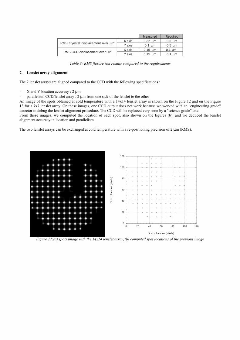
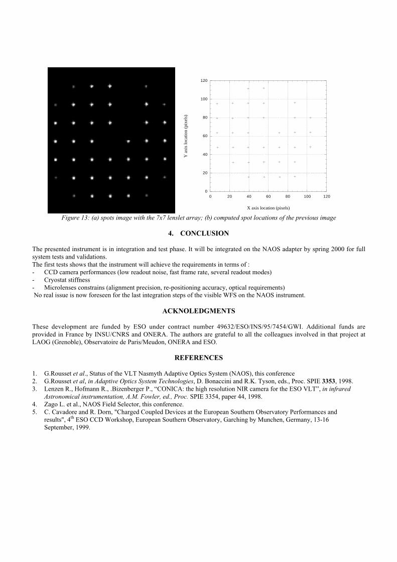
7. Lenslet array alignment
The 2 lenslet arrays are aligned compared to the CCD with the following specifications :
- X and Y location accuracy : 2 µm- parallelism CCD/lenslet array : 2 µm from one side of the lenslet to the otherAn image of the spots obtained at cold temperature with a 14x14 lenslet array is shown on the Figure 12 and on the Figure13 for a 7x7 lenslet array. On these images, one CCD output does not work because we worked with an "engineering grade"detector to debug the lenslet alignment procedure. The CCD will be replaced very soon by a "science grade" one.From these images, we computed the location of each spot, also shown on the figures (b), and we deduced the lensletalignment accuracy in location and parallelism.
The two lenslet arrays can be exchanged at cold temperature with a re-positioning precision of 2 µm (RMS).
0
20
40
60
80
100
120
0 20 40 60 80 100 120
Y a
xis
loca
tion
(pi
xels
)
X axis location (pixels)
Figure 12:(a) spots image with the 14x14 lenslet array;(b) computed spot locations of the previous image
0
20
40
60
80
100
120
0 20 40 60 80 100 120
X axis location (pixels)
Y a
xis
loca
tion
(pi
xels
)
Figure 13: (a) spots image with the 7x7 lenslet array; (b) computed spot locations of the previous image
4. CONCLUSION
The presented instrument is in integration and test phase. It will be integrated on the NAOS adapter by spring 2000 for fullsystem tests and validations.The first tests shows that the instrument will achieve the requirements in terms of :- CCD camera performances (low readout noise, fast frame rate, several readout modes)- Cryostat stiffness- Microlenses constrains (alignment precision, re-positioning accuracy, optical requirements) No real issue is now foreseen for the last integration steps of the visible WFS on the NAOS instrument.
ACKNOLEDGMENTS
These development are funded by ESO under contract number 49632/ESO/INS/95/7454/GWI. Additional funds areprovided in France by INSU/CNRS and ONERA. The authors are grateful to all the colleagues involved in that project atLAOG (Grenoble), Observatoire de Paris/Meudon, ONERA and ESO.
REFERENCES
1. G.Rousset et al., Status of the VLT Nasmyth Adaptive Optics System (NAOS), this conference2. G.Rousset et al, in Adaptive Optics System Technologies, D. Bonaccini and R.K. Tyson, eds., Proc. SPIE 3353, 1998.3. Lenzen R., Hofmann R., .Bizenberger P., “CONICA: the high resolution NIR camera for the ESO VLT”, in infrared
Astronomical instrumentation, A.M. Fowler, ed., Proc. SPIE 3354, paper 44, 1998.4. Zago L. et al., NAOS Field Selector, this conference.5. C. Cavadore and R. Dorn, "Charged Coupled Devices at the European Southern Observatory Performances and
results", 4th ESO CCD Workshop, European Southern Observatory, Garching by Munchen, Germany, 13-16September, 1999.