78
The NASA Deferred Maintenance Parametric Estimating Guide Version 2 For NASA’s Facilities Engineering Division April 21, 2003 National Aeronautics and Space Administration
| Date post: | 15-Oct-2018 |
| Category: |
Documents |
| Upload: | vuongkhuong |
| View: | 223 times |
| Download: | 0 times |
The NASA Deferred Maintenance Parametric Estimating
Guide Version 2
For NASA’s Facilities Engineering Division
April 21, 2003
National Aeronautics and Space Administration


Deferred Maintenance Guide Parametric Estimating Guide
i
Table of Contents
1. Purpose........................................................................................................................................ 1 2. Background................................................................................................................................. 1 4. The NASA DM Method - Details............................................................................................... 3
4.1 Purpose.................................................................................................................................. 3 4.2 Facility Systems .................................................................................................................... 3 4.3 Deferred Maintenance Database ........................................................................................... 3 4.4 Deferred Maintenance Categories......................................................................................... 6 4.5 System CRV Percentages ..................................................................................................... 7 4.6 Condition Assessments ......................................................................................................... 9
4.6.1 Structure..................................................................................................................... 9 4.6.2 Roof.......................................................................................................................... 10 4.6.3 Exterior .................................................................................................................... 10 4.6.4 Interior Finishes ....................................................................................................... 12 4.6.5 HVAC Systems........................................................................................................ 13 4.6.6 Electrical Systems.................................................................................................... 13 4.6.7 Plumbing Systems.................................................................................................... 13 4.6.8 Conveyance Systems ............................................................................................... 14 4.6.9 Program Support Equipment.................................................................................... 14
4.7 System Condition CRV Percentage .................................................................................... 15 4.8 System Condition Index (SCI) and Facility Condition Index (FCI) Calculations.............. 15 4.9 Deferred Maintenance Calculation ..................................................................................... 16
5. Deferred Maintenance Assessment Procedures ........................................................................ 18 5.1 Frequency of On-site Assessments ..................................................................................... 19 5.2 Performance of Assessments in Non-Visit Years............................................................... 19 5.3 Assessments of low and remote value sites not visited ...................................................... 19 5.4 Digital Photographs ............................................................................................................ 20
Appendix A. Deferred Maintenance Study................................................................................. A-1 Appendix B. Deferred Maintenance Data Collection Setup & Operation.................................. B-1 Appendix C. Database Table and Query Explanations............................................................... C-1
Deferred Maintenance Guide Parametric Estimating Guide
ii
Tables Table 1. Deferred Maintenance Category Codes and Mapping of NASA Class Codes................ 6 Table 2. System CRV percentages (continued on next page)......................................................... 8 Table 3. DM System Condition Ratings (continued next page) .................................................. 11 Table 4. System Condition CRV Percentages ............................................................................ 15 Table 5. Facility FCI Example..................................................................................................... 16 Table 6. Center FCI Example ...................................................................................................... 16 Table 7. Sample Deferred Maintenance Calculation ................................................................... 17 Table 8. NASA RPI Hierarch…………………………………………………………………...15 Table 9. Example RPI Hierarchy ................................................................................................. 17 Table C-1. Object Purpose Table................................................................................................... 1 Table C-2. Field Document 1.......................................................................................................... 3 Table C-3. Field Document 2....................................................................................................... 12
Figures Figure 1: Installing HanDBase........................................................................................................ 2 Figure 2: Enter User Name ............................................................................................................. 2 Figure 3: A “Users” dialog ............................................................................................................. 3 Figure 4: “New User” dialog .......................................................................................................... 3 Figure 5: Additional User Names ................................................................................................... 4 Figure 6: HotSync dialog ................................................................................................................ 4 Figure 7: HotSync Progress ............................................................................................................ 4 Figure 8: HotSync User list............................................................................................................. 5 Figure 9: HanDBase Installation Files folder ................................................................................. 5 Figure 10: Locate appropriate setup file ......................................................................................... 6 Figure 11: Finish Installation.......................................................................................................... 6 Figure 12: Menu.............................................................................................................................. 7 Figure 13: Select PDA to install ..................................................................................................... 7 Figure 14: Install Dialog ................................................................................................................. 8 Figure 15: Installing additional HandBase units............................................................................. 8 Figure 16: Select “Install Tool” ...................................................................................................... 9 Figure 17: “Install Tool” dialog...................................................................................................... 9 Figure 18: Select or highlight the “DM_COMMENTS.pdb” file................................................. 10 Figure 19: Dialog Box .................................................................................................................. 10 Figure 20: Select or highlight additional files............................................................................... 11 Figure 21: The “Install Tool” files list.......................................................................................... 12 Figure 22: Select the HanDBase icon ........................................................................................... 16 Figure 23: Select “DM_GSFC_TEAM_1”................................................................................... 17 Figure 24: After opening the “DM_GSFC_TEAM_1” database.................................................. 18 Figure 25: Edit Filters screen........................................................................................................ 18 Figure 26: Tap on the drop down arrow to the left of CTR.......................................................... 19 Figure 27: Select the SITE choice ................................................................................................ 19 Figure 28: Select INST from menu............................................................................................... 20 Figure 29: Enable Filter ................................................................................................................ 20
Deferred Maintenance Guide Parametric Estimating Guide
iii
Figure 30: Highlight and choose team.......................................................................................... 21 Figure 31a: Highlight Facility....................................................................................................... 22 Figure 31b: Facility drop down menu........................................................................................... 22 Figure 32a: Highlight system........................................................................................................ 23 Figure 32b: Rating popup list ....................................................................................................... 23 Figure 32c: Rate system................................................................................................................ 24 Figure 33a: Choose comments...................................................................................................... 24 Figure 33b: Select System ............................................................................................................ 25 Figure 33c: Select comment.......................................................................................................... 25 Figure 33d: Close facility.............................................................................................................. 26 Figure 33e. Enter OK.................................................................................................................... 26 Figure 34. Finished record ............................................................................................................ 27

Deferred Maintenance Guide Parametric Estimating Guide
iv
Page intentionally left blank
Deferred Maintenance Guide Parametric Estimating Guide
1
1. Purpose This guide describes the NASA Deferred Maintenance (DM) Parametric Estimating Method. The DM Method was developed and tested in 2001, and fully implemented on all NASA facilities to produce the Agency estimate of Deferred Maintenance for the annual Agency Accountability Report. The DM Method will be used annually to determine the level of deferred maintenance and the facility condition index (FCI) within NASA’s facilities inventory. The DM estimate and facility condition index information provide meaningful indicators for NASA management, and are an indicator of the level of stewardship of NASA facilities. 2. Background All Federal agencies have struggled to find an efficient and effective method to produce accurate deferred maintenance estimates. In the late 1980’s Congress focused attention on the rising levels of BMAR reported by the Department of Defense (DoD). Despite a decade of maintenance and repair funding increases to reduce maintenance backlogs, DoD’s BMAR estimate increased in the early 1990’s. DoD installations reacted to the increased funding by spending more resources on studies and inspections to further increase their BMAR estimates (in hopes that even more funding would be forthcoming). This result weakened DoD’s credibility with Congress, and has been a source of concern over the last decade. Within NASA, BMAR estimates have historically been used: to support the Agency’s Annual Accountability Report; as a functional performance metric trended over time; and as a reference point when reviewing annual maintenance budgets. The Federal Accounting Standards Advisory Board (FASAB) requires Federal agencies to comment on deferred maintenance in their Annual Accountability Reports. Previously, NASA relied upon a 1997 Facility Investment Study (FIS) as the basis for this deferred maintenance estimate. Auditors reviewing the FY 2001 Accountability Report concluded the dated FIS would no longer provide an acceptable basis for the Agency deferred maintenance estimate. In response to this audit finding, the NASA Facilities Engineering Division, “Code JX,” in cooperation with the NASA Comptroller, chartered the development of this new DM method based on a white paper by Charles B. Pittinger, Jr., P.E., dated April 8, 1999 and a National Research Council, Federal Facilities Council Standing Committee on Operations and Maintenance Technical Report #141, titled, Deferred Maintenance Reporting for Federal Facilities. The DM method provides an independent, consistent, cost–effective, and auditable approach to estimating Agency facilities deferred maintenance. The DM method was reviewed and found to be acceptable for its intended use by a nationally recognized audit firm, and a nationally known economist. The cost to generate the DM estimate was less than one cent per square foot (at least an order of magnitude less than other facility condition assessment methods). The resulting DM database provides NASA facilities managers a valuable tool for making strategic decisions regarding the NASA facilities inventory.
Deferred Maintenance Guide Parametric Estimating Guide
2
3. The NASA DM Method – An Overview The NASA DM Method involves an independent rapid visual assessment of nine different systems within each NASA facility:
• Structure • Roof • Exterior • Interior Finishes • Heating/Ventilating/Air Conditioning (HVAC) • Electrical Systems • Plumbing Systems • Conveyance Systems • Program Support Equipment
The independent assessment teams may rely upon limited input from local facilities management staff when rating each system. Systems are rated from 5 (only normal maintenance required) to 1 (system does not function as intended). These condition ratings are entered into a parametric estimating model that uses the facility current replacement value (CRV) as its basis. The CRV is apportioned between each of the nine facility systems. There are different System CRV Percentage models for each of 42 separate DM facility categories. The CRV contribution for each facility system varies for each of the 42 facility categories. For example, in complex laboratory and testing facilities, electrical systems make up a larger percentage of the overall building cost. For less complex storage facilities, electrical systems are a smaller percentage of CRV. This report lists the facility categories and System CRV Percentages for each facility system. The System CRV Percentages are derived from the Parametric Cost Estimating System (PACES)1, an accepted estimating tool for Federal construction projects. The PACES method was derived from an evaluation of more than $40 billion of federal facilities projects. The DM Method also includes System Condition CRV Percentages. Each of the five condition ratings have different System Condition CRV Percentages. For example, the System Condition CRV Percentage for a system with a 5 rating (only normal maintenance required) is 0%. This percentage drives the DM estimate for that system to $0. As ratings become progressively lower, the percentages increase (creating a higher DM estimate for that system). The System Condition CRV Percentage tables were derived using RSMeans™ CostWorks 2002 Version 6-12, which is an industry accepted estimating system.
1 PACES is an integrated PC-based parametric budgeting and cost estimating system developed by Earth Tech (http://earthtech.talpart.com.) that prepares parametric cost estimates for new facility construction and renovation. It was developed for military facility application and will soon be commercialized for use in the general building, industrial facilities, and transportation industries. PACES is available to military personnel via the U.S. Air Force. A U.S. Government employee can obtain a copy of the current military version of PACES by contacting the Air Force Civil Engineer Support Agency. 2 RSMeans™. CostWorks 2002 Version 6.1; 1996-2002. RSMeans is North America's leading supplier of construction cost information. A product line of Reed Construction Data, RSMeans provides accurate and up-to-date
Deferred Maintenance Guide Parametric Estimating Guide
3
4. The NASA DM Method - Details 4.1 Purpose The DM Method will be used annually to determine the level of deferred maintenance and the facility condition index (FCI) within NASA’s facilities inventory. The DM estimate and facility condition index information provide meaningful indicators for NASA management, and are an indicator of the level of stewardship of NASA facilities. The DM Method provides accurate deferred maintenance estimates for a large population of facilities across the entire Agency. Application of these DM data to a single or small group of facilities may produce misleading results, and likely will not match detailed Backlog of Maintenance and Repair (BMAR) estimates generated by other means, although FCIs are applicable to individual systems and facilities. 4.2 Facility Systems The DM Method is based on an assessment of nine systems for each facility. From an assessment of other deferred maintenance estimating methods that use building systems and the American Society for Testing of Materials (ASTM) UNIFORMAT II Classification for Building Elements, the following nine systems were selected for the NASA DM Method:
• Structure: Foundations, superstructure, slabs and floors, and pavements adjacent to and constructed as part of the facility (i.e., sidewalks, parking lots, access roads)
• Roofing: Roof coverings, roof openings, gutters and flashing • Exterior: Exterior coatings and sealants, windows, and doors • Interior Finishes: All interior finishes on walls, ceilings, floors, and stairways, as well as
interior doors • HVAC Systems: Heat, ventilating and air conditioning systems including controls; may
include exhaust fans, or other mechanical equipment associated with indoor air quality • Electrical Systems: Electrical service and distribution within five feet of the facility,
lighting, communications systems (phone, LAN), security and fire protection wiring and controls
• Plumbing Systems: Water, sewer and fire protection piping, including bathroom fixtures • Conveyance Systems: Elevators, escalators, cranes, hoists, or other lifting mechanisms • Program Support Equipment: Test, research and specialty equipment (installed real
property, vs. personal property associated with laboratory or testing operations) required to support testing and laboratory functions. This system normally only exists in a limited number of DM facility categories
4.3 Deferred Maintenance Database The foundation for the NASA DM Method is the deferred maintenance database. Appropriate fields from the NASA Real Property Inventory (RPI), including facility number, description, CRV, capacity, first year (essentially the year the original facility was constructed), and NASA
cost information that helps owners developers, architects, engineers, contractors and others to carefully and precisely project and control the cost of both new building construction and renovation projects
Deferred Maintenance Guide Parametric Estimating Guide
4
facility class are imported to the NASA Deferred Maintenance Database. Data for each RPI listed facility should be imported into the DM database each year, with caution exerted to ensure the appropriate CRV value is included. Additional fields within the database include: DM Categories, system condition ratings for nine systems, System CRV Percentages, System Condition CRV Percentages, DM estimates per system and for the total facility, Facility Condition Indexes (FCI), and System Condition Indexes (SCI). Individual database fields and their descriptions in the “facilities table” within the database follow:
4.3.1 Enterprise/Center/Site/Installation. Describes the primary NASA Center (and subordinate site or installation as appropriate) where the facilities reside. The “site” category includes subordinate organizations such as, Deep Space Network (DSN), Transoceanic Abort Landing Sites (TALS), Spaceflight Tracking and Data Network (STDN), Bilateration Ranging Transponder (BRT), Very Long Baseline Interferometry (VBLI) sites, and Mobile Laser Sites (MOBLAS). This database consists of all facilities that NASA owns including those remote and low value sites that may not be visited but will be assessed using the approved method found in paragraph 5.
4.3.2 Facility Number. The facility number assigned by the NASA Center taken from the RPI. This number does not change, and identifies the specific facility in question.
4.3.3 Facility Description. This field provides a brief description of the facility taken from the RPI.
4.3.4 Status. Lists whether the facility is active or inactive, (inactive sites include mothballed, abandoned, in or out grant, and heritage). Awareness of the facility status will assist the assessor in evaluating the time required and expected condition of the facility. Taken from the RPI
4.3.5 CRV (20 Cities Average). This amount is taken from the RPI. It is the primary cost input for developing the deferred maintenance estimate, and the basis for system CRV percentages used later in the spreadsheet. Note; users will need to ensure they have extracted the correct CRV from the RPI for each years DM assessment. The Center CRV’s do not include the book value of the Center’s land. This value is zeroed in the database.
4.3.6 CRV Exclusion and % Excluded. Some NASA facilities are no longer actively used. This inactivity is reflected by an entry in the CRV Exclusion field, taken directly from the NASA RPI. The year the facility was removed from inventory, and percentage of the total facility removed (some continue to be partially used), are reflected in the CRV Exclusion fields. Excluded values are included in the database to determine the full value of NASA’s deferred maintenance.
4.3.7 Capacity. This provides the quantity and unit of measure for the facility as reflected in the RPI. This information helps the assessor estimate time required to conduct the assessment.
Deferred Maintenance Guide Parametric Estimating Guide
5
4.3.8 1st Year. Provides the year the original facility was built. Provides the assessor a reference point on the age of the facility.
4.3.9 NASA Class Code. The NASA facility class code for the facility from the RPI.
4.3.10 Deferred Maintenance Category. NASA has more than 400 different facility “Classes.” These classes have been grouped into 42 “Deferred Maintenance Categories.” Each category has a separate cost model with specific CRV contributions for each facility system. Section 4.4 give a detailed explanation, and Table 1 shows the mapping of the NASA classes in to the Deferred Maintenance Categories.
4.3.11 Facility Systems. There are a series of fields to reflect the major systems to be assessed. For each of the nine systems (Structure, Roof, Exterior, Interior, HVAC, Electrical, Plumbing, Conveying, Facility Equipment), these four sub-fields are provided:
4.3.11.1 System CRV Percentage. The percentage contribution of this system to the overall facility CRV for this facility category. The percent system CRVs were developed from the Parametric Cost Estimating Systems (PACES) parametric estimating program. The final percent system CRV’s were adjusted based upon actual assessments of NASA facilities during the 2002 DM assessment. These adjustments take into account actual composition NASA’s facilities inventory. See Section 4.5 and Table 2 for the table of percentages and a detailed explanation.
4.3.11.2 System Condition Rating. The rating assigned by the assessor, from 5 (like new) to 1 (cannot support the mission). A rating of 0 is assigned if the particular systems does not exist (i.e., towers have no “interior”). See Section 4.6 and Table 3 for a detailed explanation.
4.3.11.3 System Condition CRV Percent. This percent is taken from a table based upon the system assessment rating for a given system. For example, a system assessment rating of 4 for an HVAC system produces a 2% CRV condition contribution, which factors into the facility deferred maintenance estimate. Section 4.7 and Table 4 give a detailed explanation and shows the System Condition CRV Percentage.
4.3.11.4 System Deferred Maintenance. A formula driven field, which is the product of facility CRV, System CRV Percent, and System Condition CRV Percent.
4.3.12 Facility Deferred Maintenance. This field is the sum of all nine System deferred maintenance fields. The total of this column for a given Center produces the overall Center deferred maintenance estimate. The total of all Centers deferred maintenance estimates is the Agency deferred maintenance estimate. Section 4.9 gives a detailed example of the computation.
Deferred Maintenance Guide Parametric Estimating Guide
6
4.3.13 Facility Condition Index (FCI). This is the weighted sum of condition ratings for all nine-facility systems. For each Center, the FCI is the weighted average of all nine systems for all Center facilities. For NASA it is the weighted average of all nine systems for all facilities. If a system does not exist where a System percentage is indicated, then that system’s percentage is re-distributed equally among the number of systems that do exist. Section 4.8 and Table 5 give a detailed example of this computation.
4.3.14 System Condition Index (SCI). This is the weighted average of the systems similar to the FCI from the component level to the agency level.
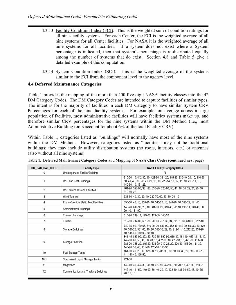
4.4 Deferred Maintenance Categories Table 1 provides the mapping of the more than 400 five digit NASA facility classes into the 42 DM Category Codes. The DM Category Codes are intended to capture facilities of similar types. The intent is for the majority of facilities in each DM Category to have similar System CRV Percentages for each of the nine facility systems. For example, on average across a large population of facilities, most administrative facilities will have facilities systems make up, and therefore similar CRV percentages for the nine systems within the DM Method (i.e., most Administrative Building roofs account for about 6% of the total Facility CRV). Within Table 1, categories listed as “buildings” will normally have most of the nine systems within the DM Method. However, categories listed as “facilities” may not be traditional buildings; they may include utility distribution systems (no roofs, interiors, etc.) or antennas (also without all nine systems). Table 1. Deferred Maintenance Category Codes and Mapping of NASA Class Codes (continued next page)
DM_FAC_CAT_CODE Facility Type NASA Facility Category Class 0 Uncategorized Facility/Building All
1 R&D and Test Buildings 610-20, 10, 442-30, 10, 423-90, 381-20, 345-10, 330-40, 20, 10, 310-60, 50, 41, 40, 30, 22, 21, 20, 15, 10, 220-14, 13, 12, 11, 10, 219-11, 10, 140-90, 10, 131-25.
2 R&D Structures and Facilities 461-90, 390-00, 381-30, 330-20, 320-60, 50, 41, 40, 30, 22, 21, 20, 10, 310-40, 22
3 Wind Tunnels 331-60, 40, 30, 20, 10, 330-70, 60, 40, 30, 20, 10
4 Engine/Vehicle Static Test Facilities 355-50, 40, 10, 350-20, 10, 345-20, 10, 340-20, 10, 310-22, 141-50
5 Administrative Buildings 140-20, 610-90, 20, 10, 381-30, 20, 310-40, 22, 10, 219-11, 140-40, 30, 20, 10, 131-90.
6 Training Buildings 610-90, 219-11, 179-00, 171-00, 140-20
7 Trailers 812-90, 712-00, 631-30, 20, 630-37, 36, 34, 32, 31, 30, 610-10, 212-10
8 Storage Buildings 740-95, 90, 730-65, 610-90, 30, 510-00, 452-10, 442-90, 50, 30, 10, 423-10, 381-20, 331-60, 40, 20, 310-30, 22, 10, 219-11, 10, 212-20, 153-90, 10, 141-40, 140-90, 50, 40
9 Storage Facilities 841-45, 833-90, 823-20, 730-65, 690-90, 610-30, 461-10, 452-12, 11, 10, 442-90, 60, 50, 40, 30, 20, 10, 432-90, 10, 423-90, 10, 421-30, 411-90, 381-20, 355-20, 345-20, 331-20, 310-22, 20, 220-10, 153-90, 141-30, 140-90, 50, 40, 131-90, 126-10, 123-90
10 Fuel Storage Tanks 461-90, 30, 20, 10, 423-90, 10, 411-90, 60, 50, 40, 30, 20, 390-00, 320-41, 141-40, 126-90,
10.1 Specialized Liquid Storage Tanks 424-30
11 Magazines 442-40, 30, 424-30, 20, 10, 423-90, 422-90, 30, 20, 15, 421-90, 310-21
12 Communication and Tracking Buildings 442-10, 141-50, 140-90, 50, 40, 20, 10, 132-10, 131-90, 50, 45, 40, 35, 20, 15, 10
Deferred Maintenance Guide Parametric Estimating Guide
7
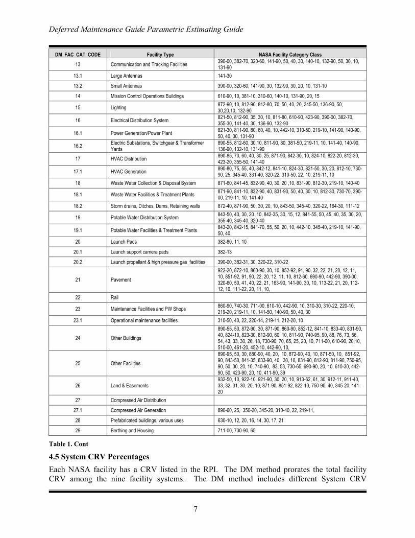
DM_FAC_CAT_CODE Facility Type NASA Facility Category Class
13 Communication and Tracking Facilities 390-00, 382-70, 320-60, 141-90, 50, 40, 30, 140-10, 132-90, 50, 30, 10, 131-90
13.1 Large Antennas 141-30
13.2 Small Antennas 390-00, 320-60, 141-90, 30, 132-90, 30, 20, 10, 131-10
14 Mission Control Operations Buildings 610-90, 10, 381-10, 310-60, 140-10, 131-90, 20, 15
15 Lighting 872-90, 10, 812-90, 812-80, 70, 50, 40, 20, 345-50, 136-90, 50, 30,20,10, 132-90
16 Electrical Distribution System 821-50, 812-90, 35, 30, 10, 811-80, 610-90, 423-90, 390-00, 382-70, 355-30, 141-40, 30, 136-90, 132-90
16.1 Power Generation/Power Plant 821-30, 811-90, 80, 60, 40, 10, 442-10, 310-50, 219-10, 141-90, 140-90, 50, 40, 30, 131-90
16.2 Electric Substations, Switchgear & Transformer Yards
890-55, 812-60, 30,10, 811-90, 80, 381-50, 219-11, 10, 141-40, 140-90, 136-90, 132-10, 131-90
17 HVAC Distribution 890-85, 70, 60, 40, 30, 25, 871-90, 842-30, 10, 824-10, 822-20, 812-30, 423-20, 355-50, 141-40
17.1 HVAC Generation 890-80, 75, 55, 40, 842-12, 841-10, 824-30, 821-50, 30, 20, 812-10, 730-90, 25, 345-40, 331-40, 320-22, 310-50, 22, 10, 219-11, 10
18 Waste Water Collection & Disposal System 871-60, 841-45, 832-90, 40, 30, 20 ,10, 831-90, 812-30, 219-10, 140-40
18.1 Waste Water Facilities & Treatment Plants 871-90, 841-10, 832-90, 40, 831-90, 50, 40, 30, 10, 812-30, 730-70, 390-00, 219-11, 10, 141-40
18.2 Storm drains, Ditches, Dams, Retaining walls 872-40, 871-90, 50, 30, 20, 10, 843-50, 345-40, 320-22, 164-30, 111-12
19 Potable Water Distribution System 843-50, 40, 30, 20 ,10, 842-35, 30, 15, 12, 841-55, 50, 45, 40, 35, 30, 20, 355-40, 345-40, 320-40
19.1 Potable Water Facilities & Treatment Plants 843-20, 842-15, 841-70, 55, 50, 20, 10, 442-10, 345-40, 219-10, 141-90, 50, 40
20 Launch Pads 382-80, 11, 10
20.1 Launch support camera pads 382-13
20.2 Launch propellant & high pressure gas facilities 390-00, 382-31, 30, 320-22, 310-22
21 Pavement 922-20, 872-10, 860-90, 30, 10, 852-92, 91, 90, 32, 22, 21, 20, 12, 11, 10, 851-92, 91, 90, 22, 20, 12, 11, 10, 812-60, 690-90, 442-90, 390-00, 320-60, 50, 41, 40, 22, 21, 163-90, 141-90, 30, 10, 113-22, 21, 20, 112-12, 10, 111-22, 20, 11, 10,
22 Rail
23 Maintenance Facilities and PW Shops 860-90, 740-30, 711-00, 610-10, 442-90, 10, 310-30, 310-22, 220-10, 219-20, 219-11, 10, 141-50, 140-90, 50, 40, 30
23.1 Operational maintenance facilities 310-50, 40, 22, 220-14, 219-11, 212-20, 10
24 Other Buildings 890-55, 50, 872-90, 30, 871-90, 860-90, 852-12, 841-10, 833-40, 831-90, 40, 824-10, 823-30, 812-90, 60, 10, 811-90, 740-95, 90, 88, 76, 73, 56, 54, 43, 33, 30, 26, 18, 730-90, 70, 65, 25, 20, 10, 711-00, 610-90, 20,10, 510-00, 461-20, 452-10, 442-90, 10,
25 Other Facilities 890-95, 50, 30, 880-90, 40, 20, 10, 872-90, 40, 10, 871-50, 10, 851-92, 90, 843-50, 841-35, 833-90, 40, 30, 10, 831-90, 812-90, 811-90, 750-95, 90, 50, 30, 20, 10, 740-90, 83, 53, 730-65, 690-90, 20, 10, 610-30, 442-90, 50, 423-90, 20, 10, 411-90, 39
26 Land & Easements 932-50, 10, 922-10, 921-90, 30, 20, 10, 913-62, 61, 30, 912-11, 911-40, 33, 32, 31, 30, 20, 10, 871-90, 851-92, 822-10, 750-90, 40, 345-20, 141-20
27 Compressed Air Distribution
27.1 Compressed Air Generation 890-60, 25, 350-20, 345-20, 310-40, 22, 219-11,
28 Prefabricated buildings, various uses 630-10, 12, 20, 16, 14, 30, 17, 21
29 Berthing and Housing 711-00, 730-90, 65
Table 1. Cont
4.5 System CRV Percentages Each NASA facility has a CRV listed in the RPI. The DM method prorates the total facility CRV among the nine facility systems. The DM method includes different System CRV
Deferred Maintenance Guide Parametric Estimating Guide
8
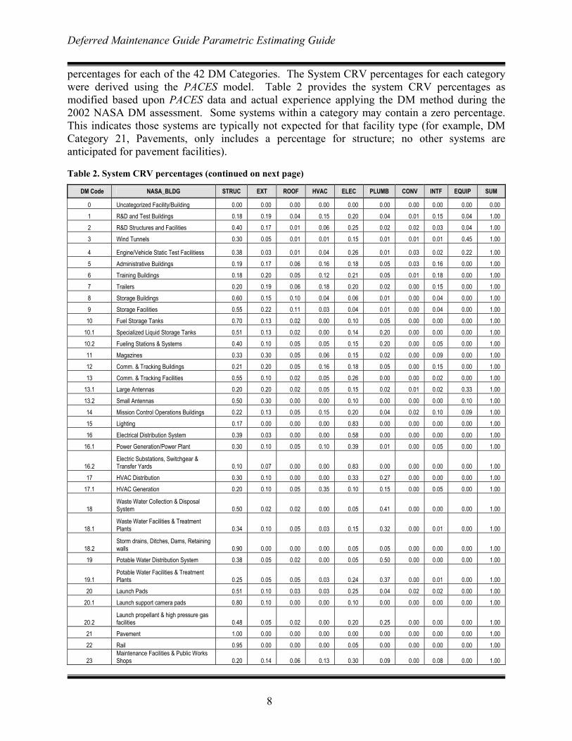
percentages for each of the 42 DM Categories. The System CRV percentages for each category were derived using the PACES model. Table 2 provides the system CRV percentages as modified based upon PACES data and actual experience applying the DM method during the 2002 NASA DM assessment. Some systems within a category may contain a zero percentage. This indicates those systems are typically not expected for that facility type (for example, DM Category 21, Pavements, only includes a percentage for structure; no other systems are anticipated for pavement facilities).
Table 2. System CRV percentages (continued on next page)
DM Code NASA_BLDG STRUC EXT ROOF HVAC ELEC PLUMB CONV INTF EQUIP SUM
0 Uncategorized Facility/Building 0.00 0.00 0.00 0.00 0.00 0.00 0.00 0.00 0.00 0.00 1 R&D and Test Buildings 0.18 0.19 0.04 0.15 0.20 0.04 0.01 0.15 0.04 1.00 2 R&D Structures and Facilities 0.40 0.17 0.01 0.06 0.25 0.02 0.02 0.03 0.04 1.00
3 Wind Tunnels 0.30 0.05 0.01 0.01 0.15 0.01 0.01 0.01 0.45 1.00
4 Engine/Vehicle Static Test Facilitiess 0.38 0.03 0.01 0.04 0.26 0.01 0.03 0.02 0.22 1.00 5 Administrative Buildings 0.19 0.17 0.06 0.16 0.18 0.05 0.03 0.16 0.00 1.00 6 Training Buildings 0.18 0.20 0.05 0.12 0.21 0.05 0.01 0.18 0.00 1.00 7 Trailers 0.20 0.19 0.06 0.18 0.20 0.02 0.00 0.15 0.00 1.00
8 Storage Buildings 0.60 0.15 0.10 0.04 0.06 0.01 0.00 0.04 0.00 1.00 9 Storage Facilities 0.55 0.22 0.11 0.03 0.04 0.01 0.00 0.04 0.00 1.00 10 Fuel Storage Tanks 0.70 0.13 0.02 0.00 0.10 0.05 0.00 0.00 0.00 1.00
10.1 Specialized Liquid Storage Tanks 0.51 0.13 0.02 0.00 0.14 0.20 0.00 0.00 0.00 1.00 10.2 Fueling Stations & Systems 0.40 0.10 0.05 0.05 0.15 0.20 0.00 0.05 0.00 1.00 11 Magazines 0.33 0.30 0.05 0.06 0.15 0.02 0.00 0.09 0.00 1.00
12 Comm. & Tracking Buildings 0.21 0.20 0.05 0.16 0.18 0.05 0.00 0.15 0.00 1.00 13 Comm. & Tracking Facilities 0.55 0.10 0.02 0.05 0.26 0.00 0.00 0.02 0.00 1.00
13.1 Large Antennas 0.20 0.20 0.02 0.05 0.15 0.02 0.01 0.02 0.33 1.00
13.2 Small Antennas 0.50 0.30 0.00 0.00 0.10 0.00 0.00 0.00 0.10 1.00 14 Mission Control Operations Buildings 0.22 0.13 0.05 0.15 0.20 0.04 0.02 0.10 0.09 1.00 15 Lighting 0.17 0.00 0.00 0.00 0.83 0.00 0.00 0.00 0.00 1.00 16 Electrical Distribution System 0.39 0.03 0.00 0.00 0.58 0.00 0.00 0.00 0.00 1.00
16.1 Power Generation/Power Plant 0.30 0.10 0.05 0.10 0.39 0.01 0.00 0.05 0.00 1.00
16.2 Electric Substations, Switchgear & Transfer Yards 0.10 0.07 0.00 0.00 0.83 0.00 0.00 0.00 0.00 1.00
17 HVAC Distribution 0.30 0.10 0.00 0.00 0.33 0.27 0.00 0.00 0.00 1.00 17.1 HVAC Generation 0.20 0.10 0.05 0.35 0.10 0.15 0.00 0.05 0.00 1.00
18 Waste Water Collection & Disposal System 0.50 0.02 0.02 0.00 0.05 0.41 0.00 0.00 0.00 1.00
18.1 Waste Water Facilities & Treatment Plants 0.34 0.10 0.05 0.03 0.15 0.32 0.00 0.01 0.00 1.00
18.2 Storm drains, Ditches, Dams, Retaining walls 0.90 0.00 0.00 0.00 0.05 0.05 0.00 0.00 0.00 1.00
19 Potable Water Distribution System 0.38 0.05 0.02 0.00 0.05 0.50 0.00 0.00 0.00 1.00
19.1 Potable Water Facilities & Treatment Plants 0.25 0.05 0.05 0.03 0.24 0.37 0.00 0.01 0.00 1.00
20 Launch Pads 0.51 0.10 0.03 0.03 0.25 0.04 0.02 0.02 0.00 1.00 20.1 Launch support camera pads 0.80 0.10 0.00 0.00 0.10 0.00 0.00 0.00 0.00 1.00
20.2 Launch propellant & high pressure gas facilities 0.48 0.05 0.02 0.00 0.20 0.25 0.00 0.00 0.00 1.00
21 Pavement 1.00 0.00 0.00 0.00 0.00 0.00 0.00 0.00 0.00 1.00 22 Rail 0.95 0.00 0.00 0.00 0.05 0.00 0.00 0.00 0.00 1.00
23 Maintenance Facilities & Public Works Shops 0.20 0.14 0.06 0.13 0.30 0.09 0.00 0.08 0.00 1.00
Deferred Maintenance Guide Parametric Estimating Guide
9
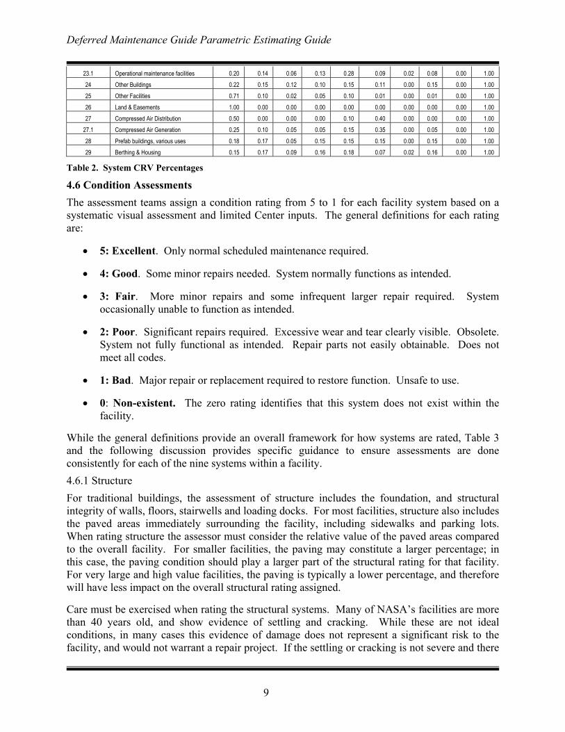
23.1 Operational maintenance facilities 0.20 0.14 0.06 0.13 0.28 0.09 0.02 0.08 0.00 1.00 24 Other Buildings 0.22 0.15 0.12 0.10 0.15 0.11 0.00 0.15 0.00 1.00 25 Other Facilities 0.71 0.10 0.02 0.05 0.10 0.01 0.00 0.01 0.00 1.00
26 Land & Easements 1.00 0.00 0.00 0.00 0.00 0.00 0.00 0.00 0.00 1.00 27 Compressed Air Distribution 0.50 0.00 0.00 0.00 0.10 0.40 0.00 0.00 0.00 1.00
27.1 Compressed Air Generation 0.25 0.10 0.05 0.05 0.15 0.35 0.00 0.05 0.00 1.00
28 Prefab buildings, various uses 0.18 0.17 0.05 0.15 0.15 0.15 0.00 0.15 0.00 1.00 29 Berthing & Housing 0.15 0.17 0.09 0.16 0.18 0.07 0.02 0.16 0.00 1.00
Table 2. System CRV Percentages
4.6 Condition Assessments The assessment teams assign a condition rating from 5 to 1 for each facility system based on a systematic visual assessment and limited Center inputs. The general definitions for each rating are:
• 5: Excellent. Only normal scheduled maintenance required.
• 4: Good. Some minor repairs needed. System normally functions as intended.
• 3: Fair. More minor repairs and some infrequent larger repair required. System occasionally unable to function as intended.
• 2: Poor. Significant repairs required. Excessive wear and tear clearly visible. Obsolete. System not fully functional as intended. Repair parts not easily obtainable. Does not meet all codes.
• 1: Bad. Major repair or replacement required to restore function. Unsafe to use.
• 0: Non-existent. The zero rating identifies that this system does not exist within the facility.
While the general definitions provide an overall framework for how systems are rated, Table 3 and the following discussion provides specific guidance to ensure assessments are done consistently for each of the nine systems within a facility. 4.6.1 Structure For traditional buildings, the assessment of structure includes the foundation, and structural integrity of walls, floors, stairwells and loading docks. For most facilities, structure also includes the paved areas immediately surrounding the facility, including sidewalks and parking lots. When rating structure the assessor must consider the relative value of the paved areas compared to the overall facility. For smaller facilities, the paving may constitute a larger percentage; in this case, the paving condition should play a larger part of the structural rating for that facility. For very large and high value facilities, the paving is typically a lower percentage, and therefore will have less impact on the overall structural rating assigned.
Care must be exercised when rating the structural systems. Many of NASA’s facilities are more than 40 years old, and show evidence of settling and cracking. While these are not ideal conditions, in many cases this evidence of damage does not represent a significant risk to the facility, and would not warrant a repair project. If the settling or cracking is not severe and there
Deferred Maintenance Guide Parametric Estimating Guide
10
is no obvious need for an immediate repair, the structural rating should be lowered no more than 1 rating.
Assessments of paving should focus on the pavement structure (deep cracking or settling would indicate a sub-surface failure, and dictate a more expensive repair), as well as the pavement surface (to include the need for seal coating of asphalt pavements).
For non-traditional buildings (antennas, tanks, pads, etc.), structure involves assessing the slab, supporting members, and adjacent pavements of the facility. Assess the overall condition, with focus on the need for maintenance or repair projects. 4.6.2 Roof Assessors can anticipate many different roof types (e.g., built up, rubber membrane, metal seam) throughout the NASA inventory. The differing roof types present different challenges for the assessors. Ratings should consider the amount of problems identified. The criteria suggest assessors should look for positive drainage. If ponding exists on a roof, one isolated incident on a large roof should not dictate a reduction in the rating; such a problem would need to be more widespread before reducing the rating.
Rubber membrane and built up roofs will show signs of aging and weathering, and roof patches will be visible to indicate past failures of portions of the roof. A visual assessment from atop theses roofs should provide adequate evidence to support a condition rating. Roofs covered in rock need to be walked and checked for evidence of bubbling or cracking. Assessors can gauge the integrity of the roof by the feel underfoot (check for air pockets, bubbling, or soft spots). For roofs with very low ratings, one should expect to see visual evidence or hear reports of leaking within the facility.
Metal seam roofs may not show signs of prior maintenance. These roofs usually leak at their seams, and repairs may be effected from underneath the roof. When assessing metal seam roofs, the assessor will need to check for evidence of leaks from within the facility, or inquire regarding past problems during the assessment.
Although age of the roof should be considered (especially for built up roofs), assessors should not arbitrarily reduce the roof ratings due to the age. In older buildings, it is likely that the roof is not original, and therefore the age of the building should not be a criterion when assessing the roof. 4.6.3 Exterior The exterior rating includes the wall coverings (e.g., paints, rust proofing, stucco), sealants (including caulking at expansion joints, doors and windows), doors and windows. For metal structures corrosion control is an element of the exterior rating. Assessors must be careful not to confuse exterior and structural ratings; evidence of structural cracking, vs. cracking in stucco or other exterior applications must be distinguished.
The rating for exterior must be based upon the entire facility appearance and condition. Some facilities are made up of multiple additions, or have differing conditions on different facades due to weather or aesthetic considerations.
Deferred Maintenance Guide Parametric Estimating Guide
11
The age of windows and doors can be a consideration in the rating for exterior. Many older NASA facilities still have single pane, lower efficiency windows and doors.
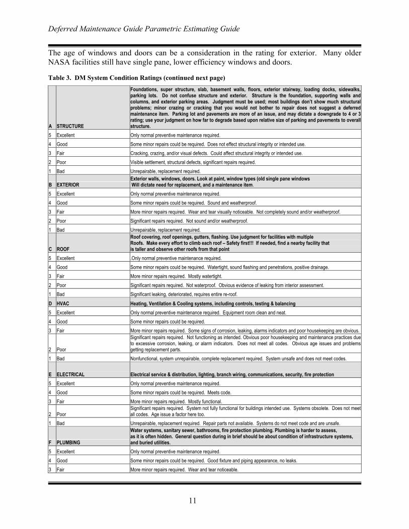
Table 3. DM System Condition Ratings (continued next page)
A STRUCTURE
Foundations, super structure, slab, basement walls, floors, exterior stairway, loading docks, sidewalks,parking lots. Do not confuse structure and exterior. Structure is the foundation, supporting walls andcolumns, and exterior parking areas. Judgment must be used; most buildings don’t show much structuralproblems; minor crazing or cracking that you would not bother to repair does not suggest a deferredmaintenance item. Parking lot and pavements are more of an issue, and may dictate a downgrade to 4 or 3rating; use your judgment on how far to degrade based upon relative size of parking and pavements to overallstructure.
5 Excellent Only normal preventive maintenance required. 4 Good Some minor repairs could be required. Does not effect structural integrity or intended use. 3 Fair Cracking, crazing, and/or visual defects. Could affect structural integrity or intended use. 2 Poor Visible settlement, structural defects, significant repairs required. 1 Bad Unrepairable, replacement required.
B EXTERIOR Exterior walls, windows, doors. Look at paint, window types (old single pane windows Will dictate need for replacement, and a maintenance item.
5 Excellent Only normal preventive maintenance required. 4 Good Some minor repairs could be required. Sound and weatherproof. 3 Fair More minor repairs required. Wear and tear visually noticeable. Not completely sound and/or weatherproof. 2 Poor Significant repairs required. Not sound and/or weatherproof. 1 Bad Unrepairable, replacement required.
C ROOF
Roof covering, roof openings, gutters, flashing. Use judgment for facilities with multiple Roofs. Make every effort to climb each roof – Safety first!!! If needed, find a nearby facility that is taller and observe other roofs from that point
5 Excellent .Only normal preventive maintenance required. 4 Good Some minor repairs could be required. Watertight, sound flashing and penetrations, positive drainage. 3 Fair More minor repairs required. Mostly watertight. 2 Poor Significant repairs required. Not waterproof. Obvious evidence of leaking from interior assessment. 1 Bad Significant leaking, deteriorated, requires entire re-roof.
D HVAC Heating, Ventilation & Cooling systems, including controls, testing & balancing 5 Excellent Only normal preventive maintenance required. Equipment room clean and neat. 4 Good Some minor repairs could be required. 3 Fair More minor repairs required. Some signs of corrosion, leaking, alarms indicators and poor housekeeping are obvious.
2 Poor
Significant repairs required. Not functioning as intended. Obvious poor housekeeping and maintenance practices dueto excessive corrosion, leaking, or alarm indicators. Does not meet all codes. Obvious age issues and problemsgetting replacement parts.
1 Bad Nonfunctional, system unrepairable, complete replacement required. System unsafe and does not meet codes.
E ELECTRICAL Electrical service & distribution, lighting, branch wiring, communications, security, fire protection 5 Excellent Only normal preventive maintenance required. 4 Good Some minor repairs could be required. Meets code. 3 Fair More minor repairs required. Mostly functional.
2 Poor Significant repairs required. System not fully functional for buildings intended use. Systems obsolete. Does not meetall codes. Age issue a factor here too.
1 Bad Unrepairable, replacement required. Repair parts not available. Systems do not meet code and are unsafe.
F PLUMBING
Water systems, sanitary sewer, bathrooms, fire protection plumbing. Plumbing is harder to assess, as it is often hidden. General question during in brief should be about condition of infrastructure systems, and buried utilities.
5 Excellent Only normal preventive maintenance required. 4 Good Some minor repairs could be required. Good fixture and piping appearance, no leaks. 3 Fair More minor repairs required. Wear and tear noticeable.
Deferred Maintenance Guide Parametric Estimating Guide
12
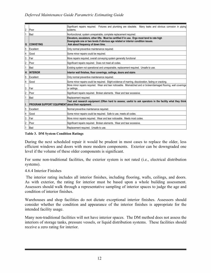
2 Poor Significant repairs required. Fixtures and plumbing are obsolete. Many leaks and obvious corrosion in pipingsystems.
1 Bad Nonfunctional, system unrepairable, complete replacement required.
G CONVEYING
Elevators, escalators, other lifts. Must be certified if in use. Ergo most tend to rate high Downgrade one or two levels if obvious age related or interior condition issues. Ask about frequency of down time.
5 Excellent Only normal preventive maintenance required. 4 Good Some minor repairs could be required. 3 Fair More repairs required, overall conveying system generally functional 2 Poor Significant repairs required. Does not meet all codes. 1 Bad Existing system not operational and unrepairable, replacement required. Unsafe to use.
H INTERIOR Interior wall finishes, floor coverings, ceilings, doors and stairs 5 Excellent Only normal preventive maintenance required. 4 Good Some minor repairs could be required. Slight evidence of marring, discoloration, fading or cracking.
3 Fair More minor repairs required. Wear and tear noticeable. Mismatched and or broken/damaged flooring, wall coveringsor ceilings.
2 Poor Significant repairs required. Broken elements. Wear and tear excessive. 1 Bad Replacement required.
I PROGRAM SUPPORT EQUIPMENTTest and research equipment (Often hard to assess; useful to ask operators in the facility what they thinkabout their equipment.
5 Excellent Normal preventive maintenance required. 4 Good Some minor repairs could be required. Safe to use, meets all codes. 3 Fair More minor repairs required. Wear and tear noticeable. Meets most codes. 2 Poor Significant repairs required. Broken elements. Wear and tear excessive. 1 Bad Replacement required. Unsafe to use.
Table 3. DM System Condition Ratings
During the next scheduled repair it would be prudent in most cases to replace the older, less efficient windows and doors with more modern components. Exterior can be downgraded one level if the volume of these older components is significant.
For some non-traditional facilities, the exterior system is not rated (i.e., electrical distribution systems). 4.6.4 Interior Finishes The interior rating includes all interior finishes, including flooring, walls, ceilings, and doors. As with exterior, the rating for interior must be based upon a whole building assessment. Assessors should walk through a representative sampling of interior spaces to judge the age and condition of interior finishes.
Warehouses and shop facilities do not dictate exceptional interior finishes. Assessors should consider whether the condition and appearance of the interior finishes is appropriate for the intended facility usage.
Many non-traditional facilities will not have interior spaces. The DM method does not assess the interiors of storage tanks, pressure vessels, or liquid distribution systems. These facilities should receive a zero rating for interior.
Deferred Maintenance Guide Parametric Estimating Guide
13
4.6.5 HVAC Systems The HVAC system includes all equipment associated with air movement, heating, or cooling within the facility. For simple facilities, it may consist of the roof mounted, wind driven exhaust fan.
Assessors should consider the overall condition of the systems, assessing a representative sampling of systems throughout the facility. Steam or condensate piping within a facility that is fed from a central plant should be rated under Plumbing.
Assessors should look at the overall condition of equipment. If a majority of HVAC system equipment is more than 20 years old, ratings should be lowered by one level. If a majority of equipment is more than 30 years old, ratings should be lowered by two levels. Assessors must exhibit judgment when rating HVAC systems, focusing on the condition of higher value, larger system components (i.e. chillers.).
Assessors should also evaluate the automated digital controls (if present) of HVAC systems. Older systems may not have any, or may have obsolete digital controls. This should be a factor in the overall rating.
Non-traditional facilities may not have HVAC systems, and should receive a zero rating for this system. 4.6.6 Electrical Systems The electrical system includes all transformers, switch gear, distribution systems, panels, and lighting within a facility. It also includes electrical components of security, communication, and fire protection systems.
Assessors should focus on the condition and appearance of maintenance or repairs within the electrical systems. Age is a significant factor in rating electrical systems. Those that are more than 20 years old should receive a downgrade of one level. Those that exceed thirty years should receive a downgrade of two levels. The assessor must not arbitrarily judge the electrical system based upon the age of the facility; he or she must visually assess a representative sampling of equipment to determine its age and condition.
Less complicated facilities may have very little electrical service. Some storage facilities may have no electrical service, and should have a zero rating for this system. 4.6.7 Plumbing Systems Plumbing includes all piping conducting fluids within the NASA facilities. Typically it includes water, condensate, and sewage piping, but it may also include piping for specialized fluids and gases.
Assessors should look for obvious signs of leaks or prior repairs in these systems. For traditional facilities, plumbing also includes the fixtures within restroom and shower facilities, and this system can be downgraded one level based upon the age and condition of piping and fixtures in these areas.
Deferred Maintenance Guide Parametric Estimating Guide
14
Plumbing systems will not be rated for exterior. Insulation or other coatings should be considered a part of the piping itself; deteriorated coatings can contribute to downgrading of the plumbing system. 4.6.8 Conveyance Systems Conveying includes all elevators and escalators, and cranes and hoists that are permanent parts of the facility. Due to safety considerations, conveying systems typically must be certified annually. If the conveying within the facility is operating the assessors should assume it is certified, and therefore at a minimum should receive no less than a 3 rating.
Conveying systems in abandoned buildings likely are not certified, and should receive no higher than a 3 rating.
Age of conveying systems is a factor, and systems should be downgraded by one level if they are more than 30 years old. 4.6.9 Program Support Equipment Program Support Equipment includes collateral3 type equipment solely required to support operations or research within the facility. Special air conditioning, electrical service, pumps, motors, exhaust systems, pressure vessels, piping, hydraulics, or other equipment needed to sustain operations or research is included within Program Support Equipment.
Program Support Equipment is expected to exist only in the following DM Facility Categories: • 1 – R&D & Test Buildings • 2 - R&D Structures and Facilities • 3 - Wind Tunnels 4 – Engine/Vehicle Static Test Facilities • 13.1 – Large Antennas • 13.2 – Small Antennas • 14 – Mission Control Operations Buildings
For most facilities outside these categories, Program Support Equipment should receive a zero rating. Special equipment within boiler plants or other infrastructure related facilities is not Program Support Equipment.
For larger antennas, hydraulics, motors, pumps, and other associated equipment in support of the antenna operations should be rated as Program Support Equipment.
3 NASA Policy Guidance (NPG) 8831.2D defines Collateral Equipment as :Encompasses building-type equipment, built-in equipment, and large, substantially affixed equipment/property and is normally acquired and installed as part of a facility project as described below
a. Building-Type Equipment. A term used in connection with facility projects to connote that equipment normally required to make a facility useful and operable. It is built in or affixed to the facility in such a manner that removal would impair the usefulness, safety, or environment of the facility. Such equipment includes elevators; heating, ventilating and air conditioning systems; transformers; compressors; and other like items generally accepted as being an inherent part of a building or structure and essential to its utility. It also includes general building systems and subsystems such as electrical, plumbing, pneumatic, fire protection, and control and monitoring systems.
b. Built-in or Large, Substantially Affixed Equipment. A term used in connection with facility projects of any type other than building-type equipment that is to be built in, affixed to, or installed in real property in such a manner that the installation cost, including special foundations or unique utilities service, or the facility restoration work required after its removal is substantial.
Deferred Maintenance Guide Parametric Estimating Guide
15
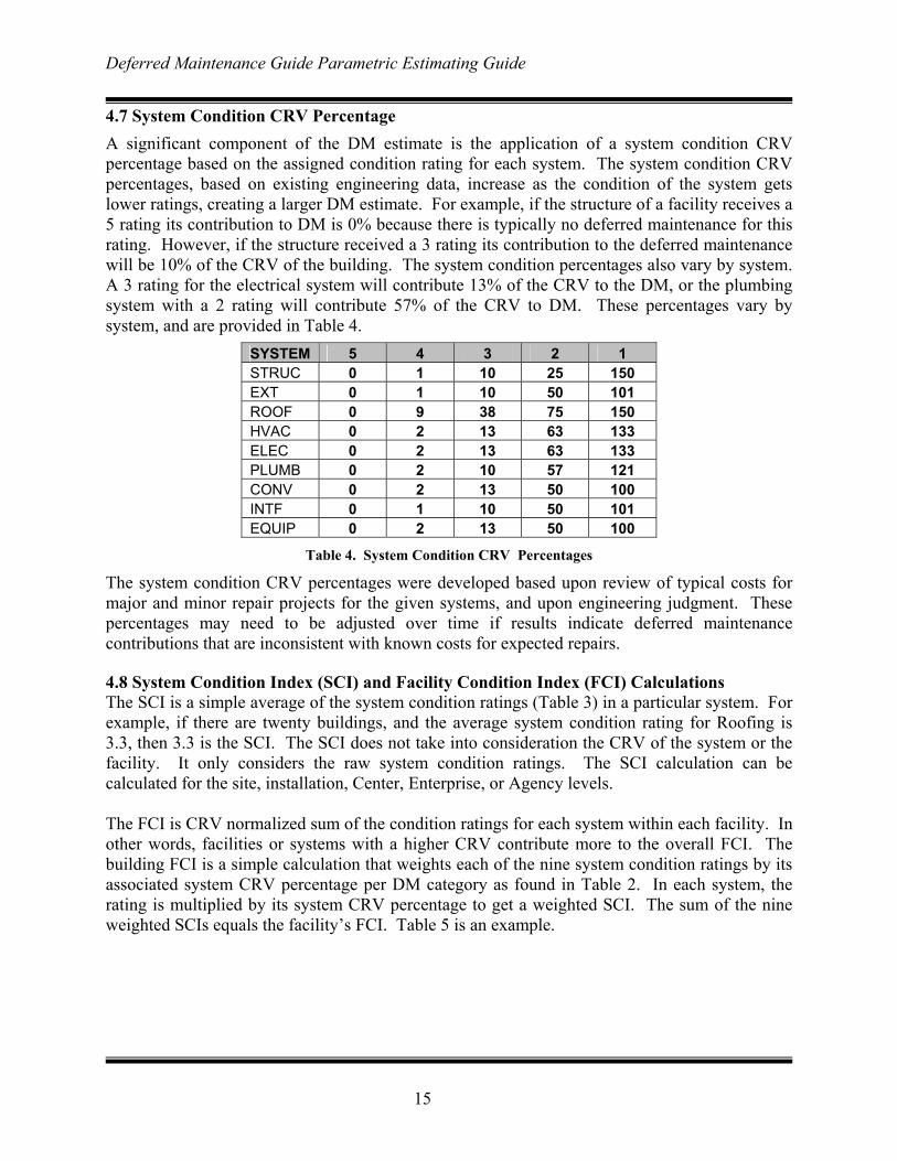
4.7 System Condition CRV Percentage A significant component of the DM estimate is the application of a system condition CRV percentage based on the assigned condition rating for each system. The system condition CRV percentages, based on existing engineering data, increase as the condition of the system gets lower ratings, creating a larger DM estimate. For example, if the structure of a facility receives a 5 rating its contribution to DM is 0% because there is typically no deferred maintenance for this rating. However, if the structure received a 3 rating its contribution to the deferred maintenance will be 10% of the CRV of the building. The system condition percentages also vary by system. A 3 rating for the electrical system will contribute 13% of the CRV to the DM, or the plumbing system with a 2 rating will contribute 57% of the CRV to DM. These percentages vary by system, and are provided in Table 4.
SYSTEM 5 4 3 2 1 STRUC 0 1 10 25 150 EXT 0 1 10 50 101 ROOF 0 9 38 75 150 HVAC 0 2 13 63 133 ELEC 0 2 13 63 133 PLUMB 0 2 10 57 121 CONV 0 2 13 50 100 INTF 0 1 10 50 101 EQUIP 0 2 13 50 100
Table 4. System Condition CRV Percentages
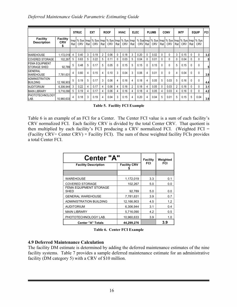
The system condition CRV percentages were developed based upon review of typical costs for major and minor repair projects for the given systems, and upon engineering judgment. These percentages may need to be adjusted over time if results indicate deferred maintenance contributions that are inconsistent with known costs for expected repairs. 4.8 System Condition Index (SCI) and Facility Condition Index (FCI) Calculations The SCI is a simple average of the system condition ratings (Table 3) in a particular system. For example, if there are twenty buildings, and the average system condition rating for Roofing is 3.3, then 3.3 is the SCI. The SCI does not take into consideration the CRV of the system or the facility. It only considers the raw system condition ratings. The SCI calculation can be calculated for the site, installation, Center, Enterprise, or Agency levels. The FCI is CRV normalized sum of the condition ratings for each system within each facility. In other words, facilities or systems with a higher CRV contribute more to the overall FCI. The building FCI is a simple calculation that weights each of the nine system condition ratings by its associated system CRV percentage per DM category as found in Table 2. In each system, the rating is multiplied by its system CRV percentage to get a weighted SCI. The sum of the nine weighted SCIs equals the facility’s FCI. Table 5 is an example.
Deferred Maintenance Guide Parametric Estimating Guide
16
STRUC EXT ROOF HVAC ELEC PLUMB CONV INTF EQUIP FCI
Facility Description
Facility CRV
$ Insp Rat
% Sys CRV
Insp Rat
% Sys CRV
Insp Rat
% Sys CRV
Insp Rat
% Sys CRV
Insp Rat
% SysCRV
Insp Rat
% Sys CRV
Insp Rat
% Sys CRV
Insp Rat
% Sys CRV
Insp Rat
% Sys CRV
WAREHOUSE 1,172,019 4 0.40 3 0.19 2 0.06 0 0.18 3 0.20 0 0.02 0 0 3 0.15 0 0 3.3COVERED STORAGE 102,267 5 0.63 5 0.22 5 0.11 0 0.03 5 0.04 0 0.01 0 0 0 0.04 0 0 5FEMA EQUIPMENT STORAGE SHED 92,789 5 0.48 5 0.17 5 0.05 0 0.15 5 0.15 0 0.15 0 0 5 0.15 0 0 5GENERAL WAREHOUSE 7,781,631 4 0.60 4 0.15 4 0.10 3 0.04 3 0.06 4 0.01 0 0 4 0.04 0 0 3.9ADMINISTRATION BUILDING 12,166,903 5 0.19 5 0.17 3 0.06 4 0.16 4 0.18 4 0.05 5 0.03 5 0.16 0 0 4.4AUDITORIUM 6,306,944 3 0.22 4 0.17 4 0.06 4 0.16 2 0.18 4 0.05 0 0.03 2 0.16 0 0 3.1MAIN LIBRARY 5,716,090 5 0.19 4 0.17 4 0.06 4 0.16 4 0.18 4 0.05 4 0.03 4 0.16 0 0 4.2PHOTOTECHNOLOGY LAB. 10,960,633 4 0.18 3 0.19 4 0.04 3 0.15 4 0.20 4 0.04 5 0.01 5 0.15 5 0.04 3.9
Table 5. Facility FCI Example
Table 6 is an example of an FCI for a Center. The Center FCI value is a sum of each facility’s CRV normalized FCI. Each facility CRV is divided by the total Center CRV. That quotient is then multiplied by each facility’s FCI producing a CRV normalized FCI. (Weighted FCI = (Facility CRV÷ Center CRV) × Facility FCI). The sum of these weighted facility FCIs provides a total Center FCI.
Center "A" Facility Description Facility CRV
$
Facility FCI
Weighted FCI
WAREHOUSE 1,172,019 3.3 0.1 COVERED STORAGE 102,267 5.0 0.0 FEMA EQUIPMENT STORAGE SHED 92,789 5.0 0.0 GENERAL WAREHOUSE 7,781,631 3.9 0.7 ADMINISTRATION BUILDING 12,166,903 4.5 1.2 AUDITORIUM 6,306,944 3.1 0.4 MAIN LIBRARY 5,716,090 4.2 0.5
PHOTOTECHNOLOGY LAB. 10,960,633 3.9 1.0
Center "A" Totals 44,299,276 3.9
Table 6. Center FCI Example
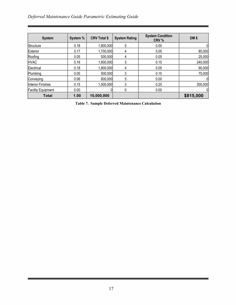
4.9 Deferred Maintenance Calculation The facility DM estimate is determined by adding the deferred maintenance estimates of the nine facility systems. Table 7 provides a sample deferred maintenance estimate for an administrative facility (DM category 5) with a CRV of $10 million.
Deferred Maintenance Guide Parametric Estimating Guide
17
System System % CRV Total $ System Rating System Condition
CRV % DM $
Structure 0.18 1,800,000 5 0.00 0Exterior 0.17 1,700,000 4 0.05 85,000Roofing 0.05 500,000 4 0.05 25,000HVAC 0.16 1,600,000 3 0.15 240,000Electrical 0.18 1,800,000 4 0.05 90,000Plumbing 0.05 500,000 3 0.15 75,000Conveying 0.06 600,000 5 0.00 0Interior Finishes 0.15 1,500,000 3 0.20 300,000Facility Equipment 0.00 0 0 0.00 0
Total 1.00 10,000,000 $815,000 Table 7. Sample Deferred Maintenance Calculation
Deferred Maintenance Guide Parametric Estimating Guide
18
5. Deferred Maintenance Assessment Procedures At least four weeks prior to the site visit, the assessment team leader assigned to a given Center should make contact with the designated Center point of contact (POC). During this initial discussion the assessment team leader should clearly articulate assessment support requirements, including escorts, special access, need for security assistance, transportation issues, or other needs. The assessment team and appropriate Center staff (maintenance staff and other Center staff with an interest in the assessment) may wish to receive a short in-brief on the first morning of the assessment. The in-brief should include introductions, an overview of the Center, and any significant current events concerning facilities by the Center staff. The assessment team leader will describe the assessment process and intended work plans for the visit. The assessment team and Center staff should agree on requirements for access, escorts, schedules and receipt and review of any pertinent information from the Center to assist in the assessment. During the assessment walk through, Center facility maintenance staff may provide short, notional facility history information for HVAC, electrical, plumbing, conveying and test equipment systems for each facility. For facilities that cannot be visually assessed (i.e., underground utilities), assessors should arrange for interviews with site staff most knowledgeable on the condition of these facilities, and base their assessment on facts related to their condition. Center fire departments may have a summary of fire department assessments including both the alarm and plumbing systems. If available, assessors may consider them in their evaluations, if appropriate. The preferred method for gathering data during the assessment is by using personal digital assistants (PDAs) with the alternate being a check sheet. Two major software components are required to allow an assessment team to use the electronic data capture method that has been developed for the NASA Deferred Maintenance/Parametric Estimating project. The first is the desktop software that allows a PDA to communicate with a desktop or laptop computer. The second is a database application for PDA’s called HanDBase. HanDBase databases for each assessment team containing the facility or building records (i.e., CRV, size, age, facility number) for each major NASA Center will be created for each site to be visited. These databases (loaded onto a Palm or PocketPC (WindowsCE) PDA) provide a method of electronically capturing assessment ratings, and comments for the nine systems that comprise each building/facility. The PDA database can also capture comments and numbering of pictures. After returning from each assessment session in the field, each PDA should be synchronized with the team leader’s laptop/desktop to backup the data that was just collected. This is important since it is easy to drop or loose a PDA, which would result in the loss of all the data collected since the last synchronization. Once the assessment has been completed and all PDA’s have been synchronized the final time, the team leader will email each assessment team’s database to the Project Manager.
Deferred Maintenance Guide Parametric Estimating Guide
19
Facility assessments will be augmented with digital photos of selected facilities or systems. Photos should be taken where feasible for systems rated as 1 or 2, and for other facilities or systems where visual evidence may help support the ratings assigned. The digital photos will become an appendix to the overall NASA Deferred Maintenance Report, and must be labeled to identify the, date, location, facility and system included in the file name. The date should be embedded in the photo image. Assessors should identify any obvious error in the NASA database (for example, a facility listed may have been demolished, or another facility at the Center may not be entered into the database). In these cases, the assessor should complete any assessments required, and note any discrepancies, which will be resolved by NASA Code JX after review of the facts surrounding the discrepancy. 5.1 Frequency of On-site Assessments The intent of the NASA DM Model is to inspect every NASA facility annually. However, visiting all sites every year may prove uneconomic in subsequent years. For this reason, NASA management may determine that full assessments may occur at an interval greater than one year. Even if the full assessment is not done annually, NASA may still want some facilities assessed in the “non-visit” years to continue the trend analysis and update records. The following methods will be used for interim assessments in “non-visit” years. 5.2 Interim Assessments In “non-visit” years, interim condition assessments will be updated on facilities as designated by Code JX (e.g., only on those facilities that have undergone minor or major repair projects (as determined by a review of NASA’s 1509 forms), or new construction projects since the previous assessment, or catastrophic events such as floods, tornadoes, etc.) These assessments will be made using the DM method in accordance with this Guide. The assessor will rate all the systems in the facilities using information from the 1509s and the property cards. The assessors will then send the raw ratings to NASA HQ (Code JX) for inclusion in the database for updating the DM estimate and the FCI as appropriate. This simple method of annual assessment will enable NASA to continue to gather maintenance cost information in the spirit of the parametric estimate. Although limited, the interim assessments will provide sufficient information on facility conditions to allow NASA to develop a DM trend line that reflects the status of its facilities maintenance program that can be used to evaluate funding required for a successful maintenance and repair program. 5.3 Assessments of low and remote value sites not visited Assessments of low value and remote sites that are not visited can be made in two ways, first, using anecdotal information and pictures from NASA employees that visit the sites regularly, and second through an RPI search and the use of the property cards within the RPI. NASA employees can offer a description of the facilities that they visit that can be used to assign ratings to each of the systems applicable to that facility. These assessments can be supported by
Deferred Maintenance Guide Parametric Estimating Guide
20
facility pictures, maintenance records and by using the property cards to provide general information. Sites that are not visited by NASA employees as frequently are more difficult to assess, but because of their low value, an approximation of an assessment provides sufficient data for the DM estimate. These sites can be assessed using the property card in the RPI, including CRV, description, and the facility systems. From the property card information one can glean the basic information required to do an assessment. Then these sites should be compared to similar facilities in the same DM category that were assessed. For example, if sites that are visited have been rated 4s and 3s then generally active sites of comparable age and structure can be assumed to be in similar condition, and deserve similar ratings. For abandoned or less active sites a similar convention can be used. If through the analysis of the data from the other site visits it was determined that over 90% of the abandoned facilities that were visited received a 1 rating, it follows that the abandoned sites not visited would be in the same condition, so on the age and likely complexity of the facility (as indicated by the CRV) the non visited sites are likely to be in a similar condition and similar ratings apply. This convention provides an acceptable and reasonable estimate within the parameters of the DM estimate; that is that over a large population of facilities the application of this convention to a very few facilities (less than 1% in number and less than .05% of the NASA CRV). 5.4 Digital Photographs As required by the statement of work digital photographs will be taken in compressed PC-JPEG format. The digital photographs shall be examples of representative existing DM that would be suitable in impact for presentations to NASA senior management. The photographs shall have file names in a format consisting of Center, facility number, and component (i.e., MSFC4420HVAC01.jpg). All digital photographs shall also have the date the photograph was taken embedded in the image area. Image resolution shall be 72dpi for web-based presentation with the RPI. Images shall be recorded/transferred onto CD-ROMs.
Deferred Maintenance Guide Parametric Estimating Guide
A-1
Appendix A. Deferred Maintenance Study Deferred Maintenance, as defined in “Deferred Maintenance/Condition Assessment Discussion Paper” dated April 8, 1999 is: “maintenance that was not performed when it should have been or was scheduled to be and which, therefore, is put off or delayed for a future period (FASAB, 1996). For purposes of this standard, maintenance is described as the act of keeping fixed assets in acceptable condition. It includes preventive maintenance, normal repairs, replacement of parts and structural components, and other activities needed to preserve the asset so that it continues to provide acceptable services and achieves its expected life.4 Maintenance excludes activities aimed at expanding the capacity of an asset or otherwise upgrading it to serve needs different from, or significantly greater than, those originally intended.” It goes on to say, “[FASAB] Standard #6, as amended, acknowledges that facilities may differ as to the level of acceptable condition, and that this level may vary across and within agencies; therefore, the standard allows facility management to determine the condition rating. Under the standard, management may estimate the amount of deferred maintenance for its agency through condition assessment surveys, a total life cycle cost method or other methods that are similar or identical to condition assessment surveys or total life-cycle cost. This study included research of literature, academia, Federal and state government agencies, and technical organizations (including the American Institute of Architects, Building Owners and Managers Association, and the International Facilities Managers Association) to determine if other organizations have used parametric estimating tools for assessing deferred maintenance. The study explains deferred maintenance estimating methods used by other agencies, and comments on the strengths and weaknesses of these methods. Background All Federal agencies have struggled to find an efficient and effective method to produce accurate deferred maintenance estimates. In the late 1980’s Congress focused attention on the rising levels of BMAR reported by the Department of Defense (DoD). Despite a decade of maintenance and repair funding increases to reduce maintenance backlogs, DoD’s BMAR estimate increased in the early 1990’s. DoD installations reacted to the increased funding by spending more resources on studies and assessments to further increase their BMAR estimates (in hopes that even more funding would be forthcoming). This result weakened DoD’s credibility with Congress, and has been a source of concern over the last decade. Within NASA, BMAR estimates have historically been used: to support the Agency’s Annual Accountability Report; as a functional performance metric trended over time; and as a reference point when reviewing annual maintenance budgets. The Federal Accounting Standards Advisory Board (FASAB) requires Federal agencies to comment on deferred maintenance in their Annual Accountability Reports. 4 Acceptable services and condition may vary both between entities and among sites within the same entity. Management shall determine what level of service and condition is acceptable.
Deferred Maintenance Guide Parametric Estimating Guide
A-2
The most recent Agency level effort to develop a deferred maintenance estimate was the Facility Investment Study (FIS) completed in 1997. The FIS estimated deferred maintenance and alteration requirements. Since 1997, the FIS has formed the basis for the Agency’s deferred maintenance estimate referenced in the Annual Accountability Reports. Auditors of the 2000 Accountability Report indicated that a new, more consistent method for estimating deferred maintenance was required for the 2001 Accountability Report. The NASA Policy Guide (NPG) 8831.2D, Facilities Maintenance Management, requires periodic condition assessments of Center facilities by completing a 100 percent assessment, or by routine assessments scheduled throughout the prescribed 5-year cycle. During Spring 2000, NASA Code JX completed a study of Center methods for developing BMAR estimates. Despite the NPG guidance, the study found significant variation in BMAR estimating between NASA Centers. Some Centers had well-established procedures for periodically producing BMAR reports based upon contractor assessments. Other Centers produced BMAR reports by assembling information from several sources only upon demand from NASA Headquarters. The costs and effort to assemble the Center BMAR estimates were also found to vary considerably. Funding from Headquarters is normally not provided to generate each Center’s BMAR estimate. Due to these variations in estimating methods, Center generated BMAR estimates are not acceptable to satisfy the Agency requirement for estimating deferred maintenance. The Federal Facilities Council (FFC) Standing Committee On Operations and Maintenance completed a study to identify issues related to the reporting of deferred maintenance for facilities. The study, “Deferred Maintenance Reporting for Federal Facilities: Meeting the Requirements of Federal Accounting Standards Advisory Board Standard Number 6, as Amended”, reviewed deferred maintenance reporting requirements as described in the Federal Accounting Standards Advisory Board, FASAB, Standard Number 6. The study reviewed alternative options for developing credible, consistent, auditable, and cost effective deferred maintenance estimates. The FFC report can be viewed on line at http://books.nap.edu/catalog/10095.html. The FFC study describes a number of methodologies for reporting deferred maintenance. Most of the methods use condition assessment surveys, life-cycle costs, or a combination of the two. Statistical approaches involving extrapolation to determine deferred maintenance were also reviewed in the study. The study concluded that the current methods being used to track and report deferred maintenance are not cost-effective, and described several ongoing efforts to devise new methods that are cost effective, consistent, and accurate. The FFC study did not advocate any particular method for estimating deferred maintenance, and did not recommend any specific method. Deferred Maintenance Estimating Methods The following paragraphs describe several methods being used to assess levels of deferred maintenance within the facilities management industry. Only the first method described, which
Deferred Maintenance Guide Parametric Estimating Guide
A-3
measures levels of deferred maintenance based upon detailed, component level assessments, actually produces a record of facility condition. The other methods are used more for budgeting purposes, and do not produce an assessment of actual facility condition. Deferred Maintenance Based Upon Detailed Assessments The most common method found for estimating deferred maintenance is to perform detailed facility inspections. These facility condition inspections, normally performed by a team of skilled craftsmen and/or engineering consultants, are costly and time consuming. Average costs for this method are $0.30 to $1.50 per square foot, depending upon the inspection rigor and detail required. This method produces a database listing all identified deficiencies and cost estimates for each deficiency (which may or may not be suitable for project development purposes). Identification of deficiencies and resultant cost estimates are subject to the skill and experience of the facility inspector. Most federal agencies use this method, inspecting each facility every 3 to 5 years, or as funding allows. FacMan Method Western Washington University, in a joint venture with the University of Washington, developed facilities management software called Facilities Manager (FacMan), to document facility condition. FacMan uses the Construction Specifications Institute’s UNIFORMAT Assembly breakdown. FacMan can be tailored to individual user desires, and is capable of handling any level of facility system detail (UNIFORMAT major systems, subsystems, or individual components). The program is based on expected life-cycle costs, not on condition assessment. When a cyclic maintenance item is not performed as scheduled it becomes part of the deferred maintenance estimate. In addition, one-time items can be manually input into the system based on field inspections. FacMan is used at Western Washington University and the University of Washington, and is also being implemented for state facilities in Wisconsin. FacMan requires users to know and enter the current age and projected life expectancy for every subsystem. BUILDER Method The Army Corps of Engineers Construction Engineering Research Laboratories and The University of Illinois developed a facilities management program called BUILDER. BUILDER is a computer-based program that inventories, assesses facility condition, predicts future deterioration thru modeling programs, and generates work requests for multi-year planning and budgeting purposes. Cost estimates are derived from Means, Whitestone, and DoD estimating guides. Data is used for the annual Installation Summary Report (ISR). Field inspections of buildings are used to rate the condition of building systems as green (excellent), amber (some problems), or red (poor condition). BUILDER is a very detailed program. For each building system there are a series of 5 to 15 components that are evaluated. Facility inspectors evaluate these components to determine an overall rating (red/amber/green) for each system. The BUILDER database generates a cost estimate to bring systems back to the green condition rating. Adding the costs to convert all
Deferred Maintenance Guide Parametric Estimating Guide
A-4
building systems back to a green condition produces the equivalent of a deferred maintenance estimate for that facility. Washington State Department Of Transportation Method The Washington State Department of Transportation (WSDOT) developed a system to assess the criticality of its facilities. The rating produced is a combination of the importance of a particular facility and the current condition of the facility. This method does not produce a dollar estimate for deferred maintenance. The WSDOT method uses a two-page rating format that analyzes each of nine components for each facility. Each component is inspected and assigned a numerical rating (1 = excellent to 5 = does not meet standards) based on guideline criteria. A weighting multiplier is applied based on the criticality of the individual component. The system produces a condition rating (raw number) for each facility. Higher numbers indicate more critical facility maintenance issues. For example, a facility without a fire-protection system would receive a rating of 5 for the “Safety Standards” component. Each component has a multiplier; the multiplier for the component “Safety Standards” is a 10 because it relates to life safety. The multiplier ranges from 2 to 10. The condition rating for this facility for the Safety Standard component would be a 50, (5 x 10). The total facility scores are the total of all subsystem scores. Facilities are then ranked by score, with funding priority going to facilities with the highest scores. Facility Sustainment Model The Office of the Secretary of Defense (OSD) has developed the Facility Sustainment Model (FSM) to determine annual maintenance funding requirements for Federal facilities. The FSM estimates the costs to sustain facilities at their current condition level. It does not assess costs for required repairs to restore facilities to acceptable condition levels. Inputs for the FSM model are: total square footage of facilities by facility category; annual cost per square foot for maintenance based upon the DoD Cost Factor Handbook; area cost factors; and inflation.
Facilities Management Institute Method The Facility Management Institute (FMI), a subsidiary of Herman Miller, Inc., developed a formula to calculate annual maintenance costs for buildings. Building age and current value are two of the most important factors in determining maintenance costs. The method does not involve facility inspections. The deferred maintenance estimate is generated based upon a formula comparing facility age and expected useful life. As facilities age, and consume increasing percentages of their expected useful life, the deferred maintenance estimate increases. This method does not account for ongoing maintenance in facilities.
Deferred Maintenance Guide Parametric Estimating Guide
B-1
Appendix B. Deferred Maintenance Data Collection Setup & Operation Overview Two major software components are required to allow an inspection team to use the electronic data capture method that has been developed for the NASA Deferred Maintenance/Parametric Estimating project. The first is the desktop software that allows a Personal Digital Assistant (PDA) to communicate with a desktop or laptop computer. The second is a database application for PDA’s called HanDBase. HanDBase databases for each assessment team containing the facility or building records for each major NASA Center have been created. These databases (loaded onto a Palm or PocketPC (WindowsCE) PDA) provide a method of electronically capturing assessment ratings and comments for the nine systems that comprise each building/facility. The planned approach to gathering the inspection data involves an assessment group for a NASA Center/Site/Installation that is composed of one or more two-person teams. An assessment group should have a desktop/laptop available that will be used to synchronize the PDA’s with. This desktop/laptop must have the Palm and/or PocketPC desktop installed. Each two-person team will have one PDA to record the assessment ratings. Prior to beginning the assessment, an assessment group should verify that each PDA will properly synchronize with the desktop/laptop and that there are no conflicts between the database names installed to each PDA. One option is for the assessment group leader to provide the desktop/laptop that the assessment teams will use for synchronization. After returning from each assessment session in the field, each PDA should by synchronized with the team leader’s laptop/desktop to backup the data that was just collected. This is important since it is easy to drop or loose a PDA, which would result in the loss of all the data collected since the last synchronization. Once the assessment has been completed and all PDA’s have been synchronized the final time, the team leader will email each assessment team’s database to the Project Manager. Installing Palm Desktop & HotSync Manager The goal of this section is to install the Palm Desktop & HotSync Manager (HotSync Manager is automatically installed with the Desktop application) software to one desktop/laptop that will be used as the assessment groups “main” data repository. The Palm or PocketPC desktop/laptop software should be installed on one desktop/laptop; the desktop/laptop that will be used to synchronize the team’s PDA’s. If each assessment team has a laptop available, it is acceptable for an assessment team to synchronize their PDA with their laptop. Regardless, each desktop/laptop that will be used to synchronize PDA’s must have the Palm and/or PocketPC software installed.
1. If you do not already have a PDA with its desktop software installed, it should be installed as instructed below before installing HanDBase. If you already have Palm Desktop & HotSync Manager software installed, continue with step 5 below.
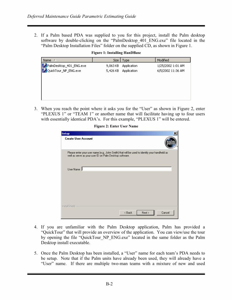
Deferred Maintenance Guide Parametric Estimating Guide
B-2
2. If a Palm based PDA was supplied to you for this project, install the Palm desktop
software by double-clicking on the “PalmDesktop_401_ENG.exe” file located in the “Palm Desktop Installation Files” folder on the supplied CD, as shown in Figure 1.
Figure 1: Installing HanDBase
3. When you reach the point where it asks you for the “User” as shown in Figure 2, enter “PLEXUS 1” or “TEAM 1” or another name that will facilitate having up to four users with essentially identical PDA’s. For this example, “PLEXUS 1” will be entered.
Figure 2: Enter User Name
4. If you are unfamiliar with the Palm Desktop application, Palm has provided a
“QuickTour” that will provide an overview of the application. You can view/use the tour by opening the file “QuickTour_NP_ENG.exe” located in the same folder as the Palm Desktop install executable.
5. Once the Palm Desktop has been installed, a “User” name for each team’s PDA needs to
be setup. Note that if the Palm units have already been used, they will already have a “User” name. If there are multiple two-man teams with a mixture of new and used
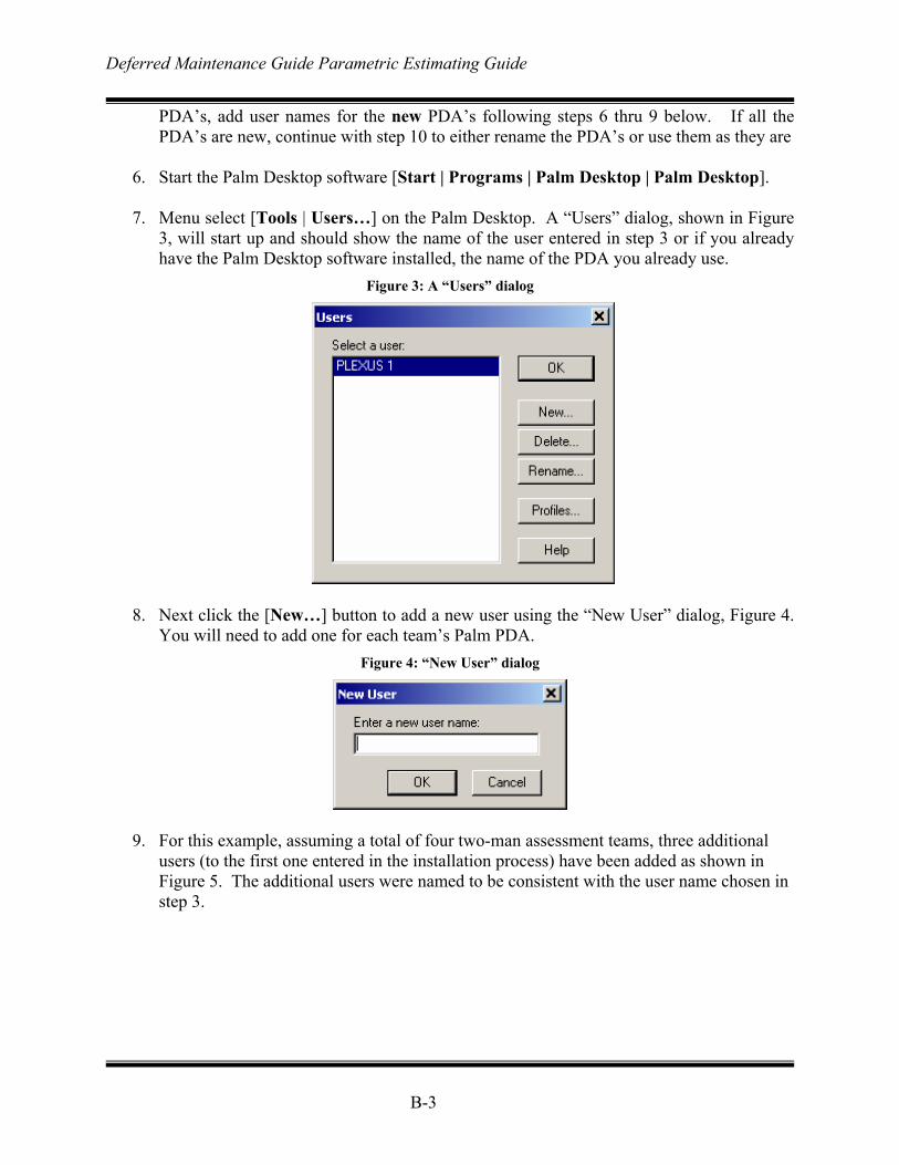
Deferred Maintenance Guide Parametric Estimating Guide
B-3
PDA’s, add user names for the new PDA’s following steps 6 thru 9 below. If all the PDA’s are new, continue with step 10 to either rename the PDA’s or use them as they are
6. Start the Palm Desktop software [Start | Programs | Palm Desktop | Palm Desktop].
7. Menu select [Tools | Users…] on the Palm Desktop. A “Users” dialog, shown in Figure
3, will start up and should show the name of the user entered in step 3 or if you already have the Palm Desktop software installed, the name of the PDA you already use.
Figure 3: A “Users” dialog
8. Next click the [New…] button to add a new user using the “New User” dialog, Figure 4.
You will need to add one for each team’s Palm PDA. Figure 4: “New User” dialog
9. For this example, assuming a total of four two-man assessment teams, three additional users (to the first one entered in the installation process) have been added as shown in Figure 5. The additional users were named to be consistent with the user name chosen in step 3.
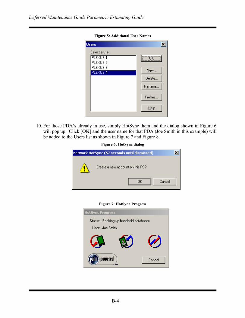
Deferred Maintenance Guide Parametric Estimating Guide
B-4
Figure 5: Additional User Names
10. For those PDA’s already in use, simply HotSync them and the dialog shown in Figure 6
will pop up. Click [OK] and the user name for that PDA (Joe Smith in this example) will be added to the Users list as shown in Figure 7 and Figure 8.
Figure 6: HotSync dialog
Figure 7: HotSync Progress
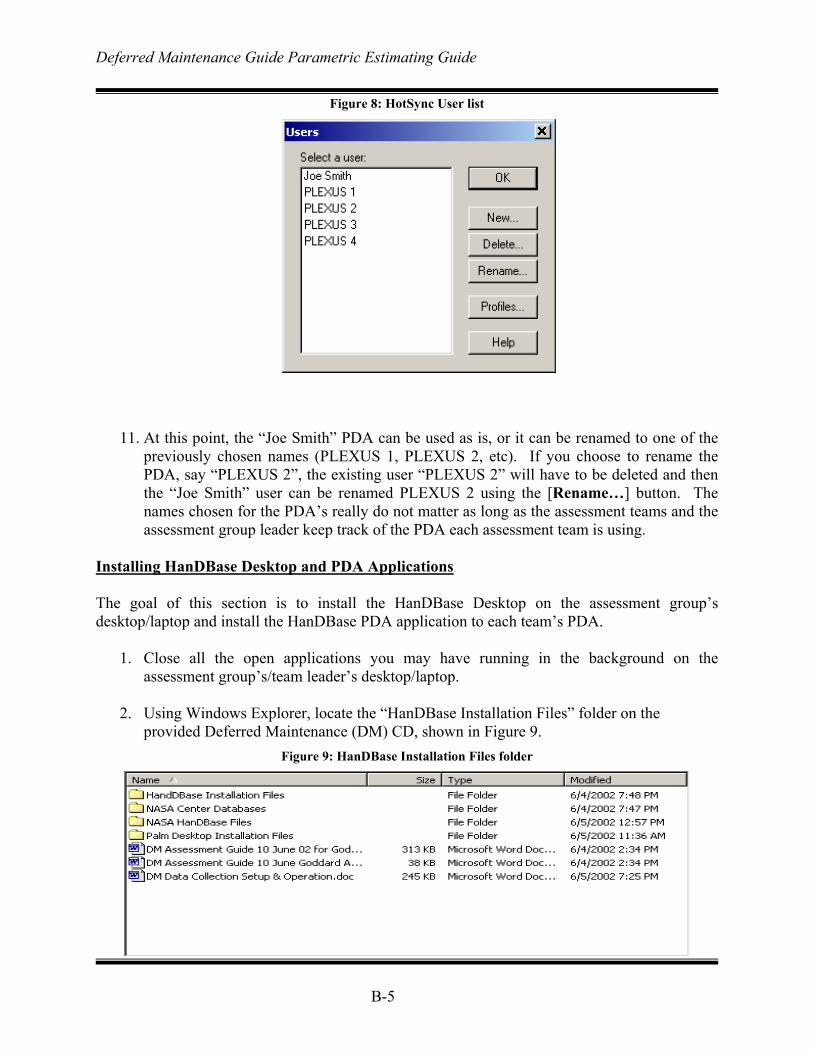
Deferred Maintenance Guide Parametric Estimating Guide
B-5
Figure 8: HotSync User list
11. At this point, the “Joe Smith” PDA can be used as is, or it can be renamed to one of the
previously chosen names (PLEXUS 1, PLEXUS 2, etc). If you choose to rename the PDA, say “PLEXUS 2”, the existing user “PLEXUS 2” will have to be deleted and then the “Joe Smith” user can be renamed PLEXUS 2 using the [Rename…] button. The names chosen for the PDA’s really do not matter as long as the assessment teams and the assessment group leader keep track of the PDA each assessment team is using.
Installing HanDBase Desktop and PDA Applications The goal of this section is to install the HanDBase Desktop on the assessment group’s desktop/laptop and install the HanDBase PDA application to each team’s PDA.
1. Close all the open applications you may have running in the background on the assessment group’s/team leader’s desktop/laptop.
2. Using Windows Explorer, locate the “HanDBase Installation Files” folder on the
provided Deferred Maintenance (DM) CD, shown in Figure 9. Figure 9: HanDBase Installation Files folder
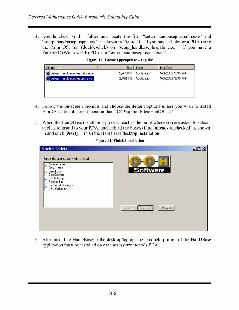
Deferred Maintenance Guide Parametric Estimating Guide
B-6
3. Double click on this folder and locate the files “setup_handbasepluspalm.exe” and
“setup_handbaseplusppc.exe” as shown in Figure 10. If you have a Palm or a PDA using the Palm OS, run (double-click) on “setup_handbasepluspalm.exe.” If you have a PocketPC (WindowsCE) PDA run “setup_handbaseplusppc.exe.”
Figure 10: Locate appropriate setup file
4. Follow the on-screen prompts and choose the default options unless you wish to install HanDBase to a different location than “C:\Program Files\HanDBase”.
5. When the HanDBase installation process reaches the point where you are asked to select
applets to install to your PDA, uncheck all the boxes (if not already unchecked) as shown in and click [Next]. Finish the HanDBase desktop installation.
Figure 11: Finish Installation
6. After installing HanDBase to the desktop/laptop, the handheld portion of the HanDBase
application must be installed on each assessment team’s PDA.
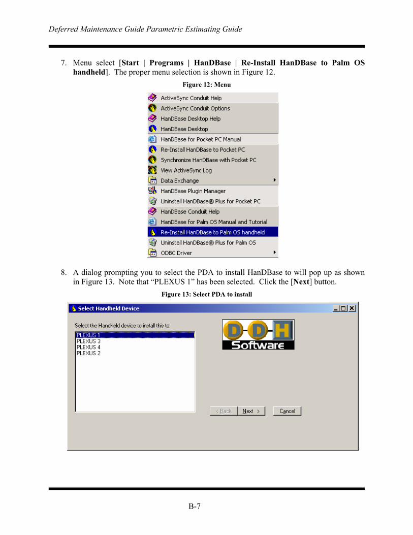
Deferred Maintenance Guide Parametric Estimating Guide
B-7
7. Menu select [Start | Programs | HanDBase | Re-Install HanDBase to Palm OS
handheld]. The proper menu selection is shown in Figure 12. Figure 12: Menu
8. A dialog prompting you to select the PDA to install HanDBase to will pop up as shown in Figure 13. Note that “PLEXUS 1” has been selected. Click the [Next] button.
Figure 13: Select PDA to install
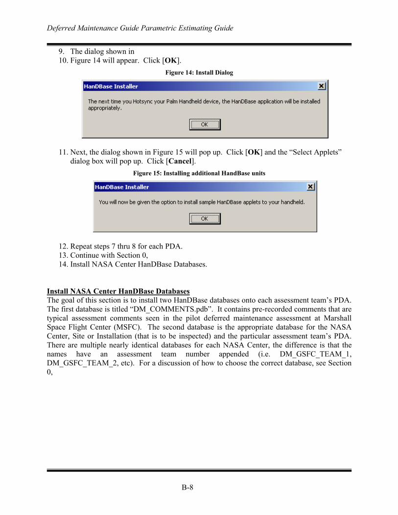
Deferred Maintenance Guide Parametric Estimating Guide
B-8
9. The dialog shown in 10. Figure 14 will appear. Click [OK].
Figure 14: Install Dialog
11. Next, the dialog shown in Figure 15 will pop up. Click [OK] and the “Select Applets”
dialog box will pop up. Click [Cancel]. Figure 15: Installing additional HandBase units
12. Repeat steps 7 thru 8 for each PDA. 13. Continue with Section 0, 14. Install NASA Center HanDBase Databases.
Install NASA Center HanDBase Databases The goal of this section is to install two HanDBase databases onto each assessment team’s PDA. The first database is titled “DM_COMMENTS.pdb”. It contains pre-recorded comments that are typical assessment comments seen in the pilot deferred maintenance assessment at Marshall Space Flight Center (MSFC). The second database is the appropriate database for the NASA Center, Site or Installation (that is to be inspected) and the particular assessment team’s PDA. There are multiple nearly identical databases for each NASA Center, the difference is that the names have an assessment team number appended (i.e. DM_GSFC_TEAM_1, DM_GSFC_TEAM_2, etc). For a discussion of how to choose the correct database, see Section 0,
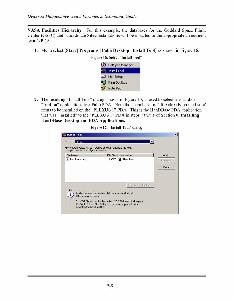
Deferred Maintenance Guide Parametric Estimating Guide
B-9
NASA Facilities Hierarchy. For this example, the databases for the Goddard Space Flight Center (GSFC) and subordinate Sites/Installations will be installed to the appropriate assessment team’s PDA.
1. Menu select [Start | Programs | Palm Desktop | Install Tool] as shown in Figure 16. Figure 16: Select “Install Tool”
2. The resulting “Install Tool” dialog, shown in Figure 17, is used to select files and/or
“Add-on” applications to a Palm PDA. Note the “handbase.prc” file already on the list of items to be installed on the “PLEXUS 1” PDA. This is the HanDBase PDA application that was “installed” to the “PLEXUS 1” PDA in steps 7 thru 8 of Section 0, Installing HanDBase Desktop and PDA Applications.
Figure 17: “Install Tool” dialog
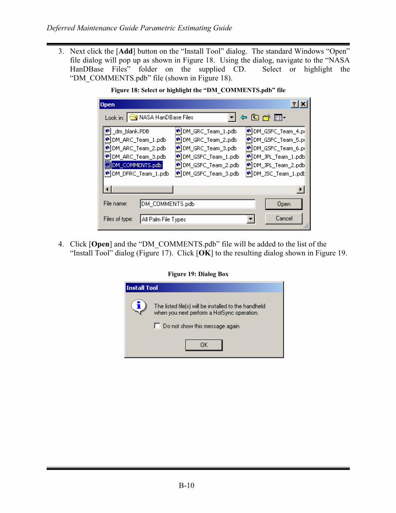
Deferred Maintenance Guide Parametric Estimating Guide
B-10
3. Next click the [Add] button on the “Install Tool” dialog. The standard Windows “Open” file dialog will pop up as shown in Figure 18. Using the dialog, navigate to the “NASA HanDBase Files” folder on the supplied CD. Select or highlight the “DM_COMMENTS.pdb” file (shown in Figure 18).
Figure 18: Select or highlight the “DM_COMMENTS.pdb” file
4. Click [Open] and the “DM_COMMENTS.pdb” file will be added to the list of the “Install Tool” dialog (Figure 17). Click [OK] to the resulting dialog shown in Figure 19.
Figure 19: Dialog Box
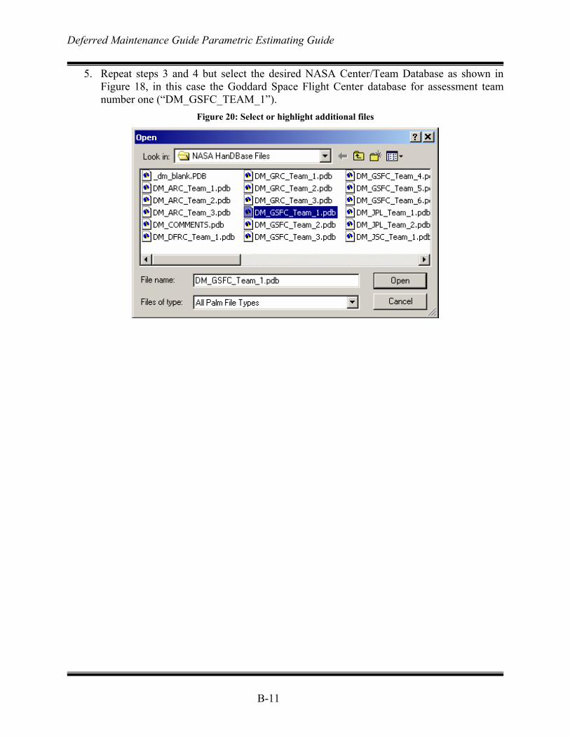
Deferred Maintenance Guide Parametric Estimating Guide
B-11
5. Repeat steps 3 and 4 but select the desired NASA Center/Team Database as shown in Figure 18, in this case the Goddard Space Flight Center database for assessment team number one (“DM_GSFC_TEAM_1”).
Figure 20: Select or highlight additional files
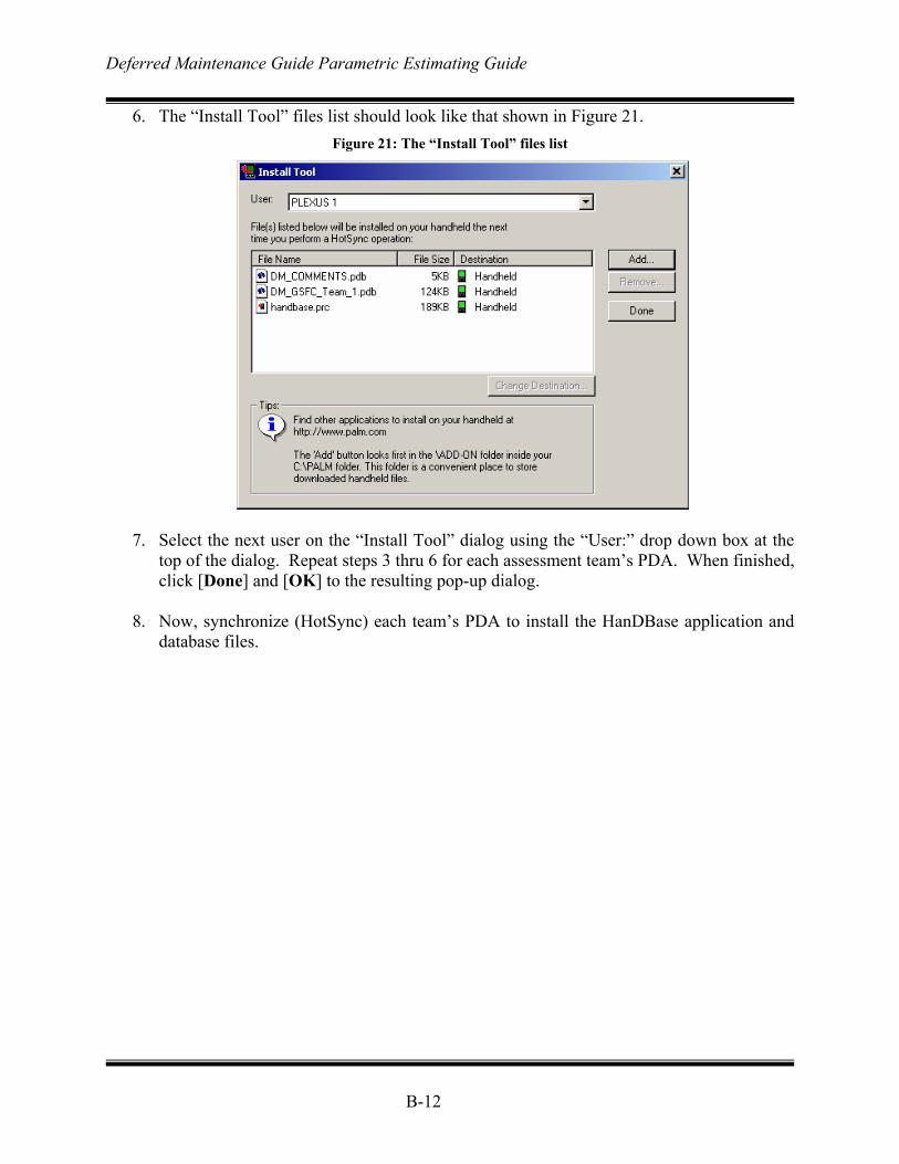
Deferred Maintenance Guide Parametric Estimating Guide
B-12
6. The “Install Tool” files list should look like that shown in Figure 21. Figure 21: The “Install Tool” files list
7. Select the next user on the “Install Tool” dialog using the “User:” drop down box at the
top of the dialog. Repeat steps 3 thru 6 for each assessment team’s PDA. When finished, click [Done] and [OK] to the resulting pop-up dialog.
8. Now, synchronize (HotSync) each team’s PDA to install the HanDBase application and
database files.
Deferred Maintenance Guide Parametric Estimating Guide
B-13
NASA Facilities Hierarchy The NASA facility records in the Real Property Inventory (RPI) are arranged hierarchically by responsible NASA Centers. NASA basically has a three level hierarchy for its real property. In the absence of an approved NASA name for each “level” of the hierarchy, the following names and abbreviations were chosen:
NASA Center (CTR): Topmost responsible NASA facility. NASA Site (SITE): A NASA facility that is subordinate to a NASA Center. NASA Installation (INST): A NASA facility that is subordinate to a NASA Site, that
is in turn subordinate to a NASA Center. Table details the NASA RPI hierarchy. HandDBase allows two levels of “filters”. Since each NASA Center is in its own database, two levels of filters are sufficient to screen or “filter” each Center database for all existing combinations of SITE and INST. In other words, the two filters in HandDBase can be used to select only those records corresponding to the NASA facility that is being inspected. The table below is provided so that each inspector can determine the correct filter entries for the NASA facilities that they will be inspecting. For instance, say one assessment team will be inspecting the Ames Research Center. Prior to starting their assessment, they would install the DM_ARC database on their Palm/PocketPC handheld. Then, to screen or “filter” out the records for Crows Landing, Camp Parks and Moffet Federal Airfield, the inspector would enter a dash (-) in each of the two filters in HandDBase. Then the HandDBase application would only show those records that have “ARC” for CTR, “-“ for SITE and “-“ for INST. Similarly, if another assessment team was tasked with inspecting Moffet Federal Airfield, they would enter “ARC” for CTR, “MFA” for SITE and “-“ for INST. Note that the field CTR is not used in the filter since all the records in each database belong to one NASA Center.
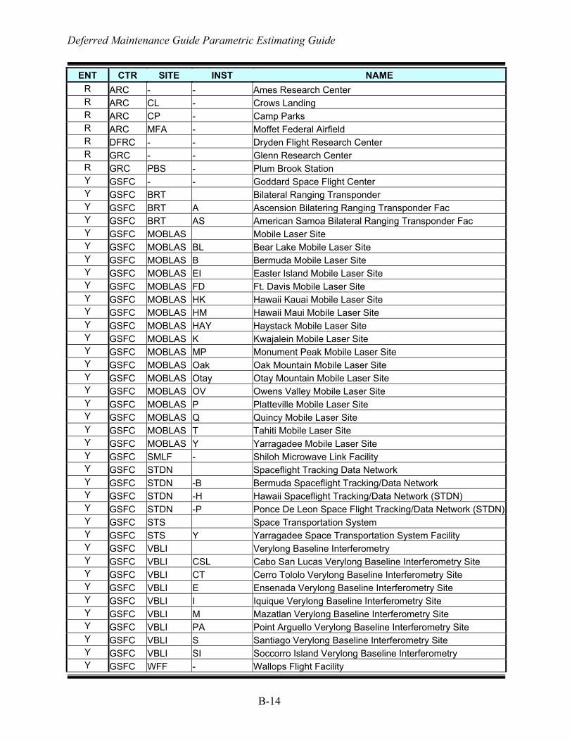
Deferred Maintenance Guide Parametric Estimating Guide
B-14
ENT CTR SITE INST NAME R ARC - - Ames Research Center R ARC CL - Crows Landing R ARC CP - Camp Parks R ARC MFA - Moffet Federal Airfield R DFRC - - Dryden Flight Research Center R GRC - - Glenn Research Center R GRC PBS - Plum Brook Station Y GSFC - - Goddard Space Flight Center Y GSFC BRT Bilateral Ranging Transponder Y GSFC BRT A Ascension Bilatering Ranging Transponder Fac Y GSFC BRT AS American Samoa Bilateral Ranging Transponder Fac Y GSFC MOBLAS Mobile Laser Site Y GSFC MOBLAS BL Bear Lake Mobile Laser Site Y GSFC MOBLAS B Bermuda Mobile Laser Site Y GSFC MOBLAS EI Easter Island Mobile Laser Site Y GSFC MOBLAS FD Ft. Davis Mobile Laser Site Y GSFC MOBLAS HK Hawaii Kauai Mobile Laser Site Y GSFC MOBLAS HM Hawaii Maui Mobile Laser Site Y GSFC MOBLAS HAY Haystack Mobile Laser Site Y GSFC MOBLAS K Kwajalein Mobile Laser Site Y GSFC MOBLAS MP Monument Peak Mobile Laser Site Y GSFC MOBLAS Oak Oak Mountain Mobile Laser Site Y GSFC MOBLAS Otay Otay Mountain Mobile Laser Site Y GSFC MOBLAS OV Owens Valley Mobile Laser Site Y GSFC MOBLAS P Platteville Mobile Laser Site Y GSFC MOBLAS Q Quincy Mobile Laser Site Y GSFC MOBLAS T Tahiti Mobile Laser Site Y GSFC MOBLAS Y Yarragadee Mobile Laser Site Y GSFC SMLF - Shiloh Microwave Link Facility Y GSFC STDN Spaceflight Tracking Data Network Y GSFC STDN -B Bermuda Spaceflight Tracking/Data Network Y GSFC STDN -H Hawaii Spaceflight Tracking/Data Network (STDN) Y GSFC STDN -P Ponce De Leon Space Flight Tracking/Data Network (STDN)Y GSFC STS Space Transportation System Y GSFC STS Y Yarragadee Space Transportation System Facility Y GSFC VBLI Verylong Baseline Interferometry Y GSFC VBLI CSL Cabo San Lucas Verylong Baseline Interferometry Site Y GSFC VBLI CT Cerro Tololo Verylong Baseline Interferometry Site Y GSFC VBLI E Ensenada Verylong Baseline Interferometry Site Y GSFC VBLI I Iquique Verylong Baseline Interferometry Site Y GSFC VBLI M Mazatlan Verylong Baseline Interferometry Site Y GSFC VBLI PA Point Arguello Verylong Baseline Interferometry Site Y GSFC VBLI S Santiago Verylong Baseline Interferometry Site Y GSFC VBLI SI Soccorro Island Verylong Baseline Interferometry Y GSFC WFF - Wallops Flight Facility
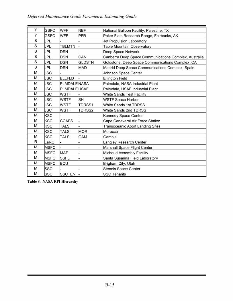
Deferred Maintenance Guide Parametric Estimating Guide
B-15
Y GSFC WFF NBF National Balloon Facility, Palestine, TX Y GSFC WFF PFR Poker Flats Research Range, Fairbanks, AK S JPL - - Jet Propulsion Laboratory S JPL TBLMTN - Table Mountain Observatory S JPL DSN - Deep Space Network S JPL DSN CAN Canberra Deep Space Communications Complex, Australia S JPL DSN GLDSTN Goldstone, Deep Space Communications Complex ,CA S JPL DSN MAD Madrid Deep Space Communications Complex, Spain M JSC - - Johnson Space Center M JSC ELLFLD - Ellington Field M JSC PLMDALE NASA Palmdale, NASA Industrial Plant M JSC PLMDALE USAF Palmdale, USAF Industrial Plant M JSC WSTF - White Sands Test Facility M JSC WSTF SH WSTF Space Harbor M JSC WSTF TDRSS1 White Sands 1st TDRSS M JSC WSTF TDRSS2 White Sands 2nd TDRSS M KSC - - Kennedy Space Center M KSC CCAFS - Cape Canaveral Air Force Station M KSC TALS - Transoceanic Abort Landing Sites M KSC TALS MOR Morocco M KSC TALS GAM Gambia R LaRC - - Langley Research Center M MSFC - - Marshall Space Flight Center M MSFC MAF - Michoud Assembly Facility M MSFC SSFL - Santa Susanna Field Laboratory M MSFC BCU Brigham City, Utah M SSC - - Stennis Space Center M SSC SSCTEN - SSC Tenants
Table 8. NASA RPI Hierarchy
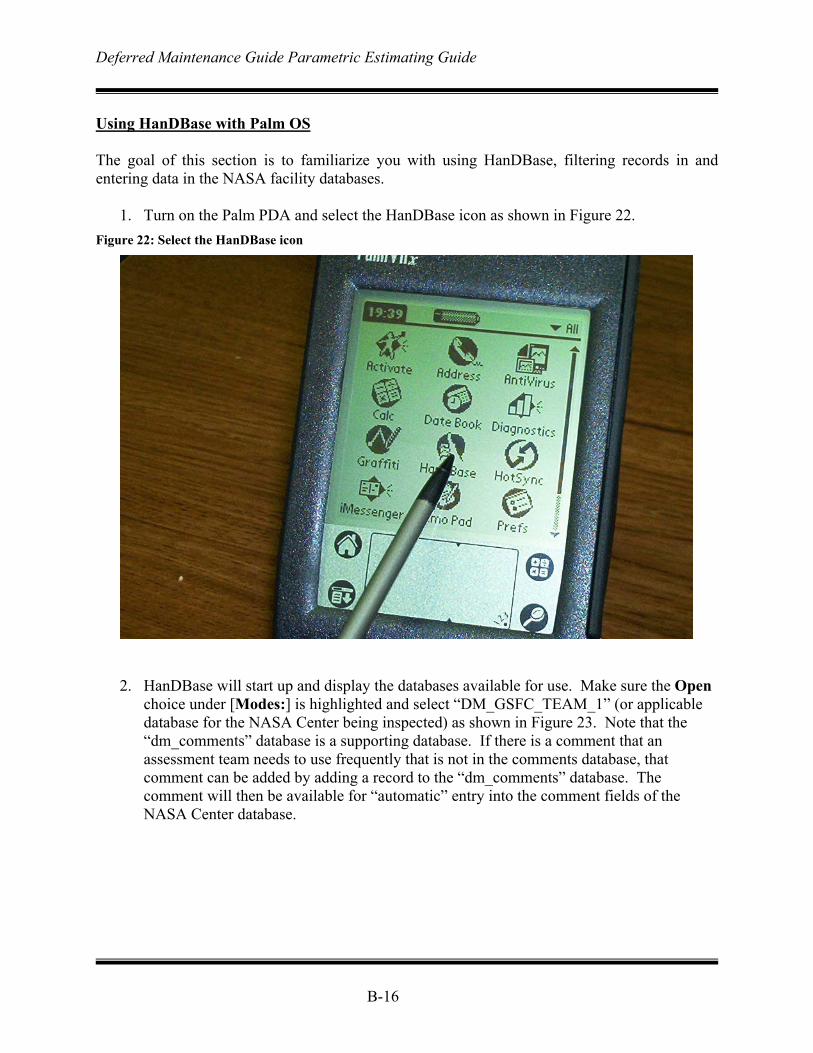
Deferred Maintenance Guide Parametric Estimating Guide
B-16
Using HanDBase with Palm OS The goal of this section is to familiarize you with using HanDBase, filtering records in and entering data in the NASA facility databases.
1. Turn on the Palm PDA and select the HanDBase icon as shown in Figure 22. Figure 22: Select the HanDBase icon
2. HanDBase will start up and display the databases available for use. Make sure the Open
choice under [Modes:] is highlighted and select “DM_GSFC_TEAM_1” (or applicable database for the NASA Center being inspected) as shown in Figure 23. Note that the “dm_comments” database is a supporting database. If there is a comment that an assessment team needs to use frequently that is not in the comments database, that comment can be added by adding a record to the “dm_comments” database. The comment will then be available for “automatic” entry into the comment fields of the NASA Center database.
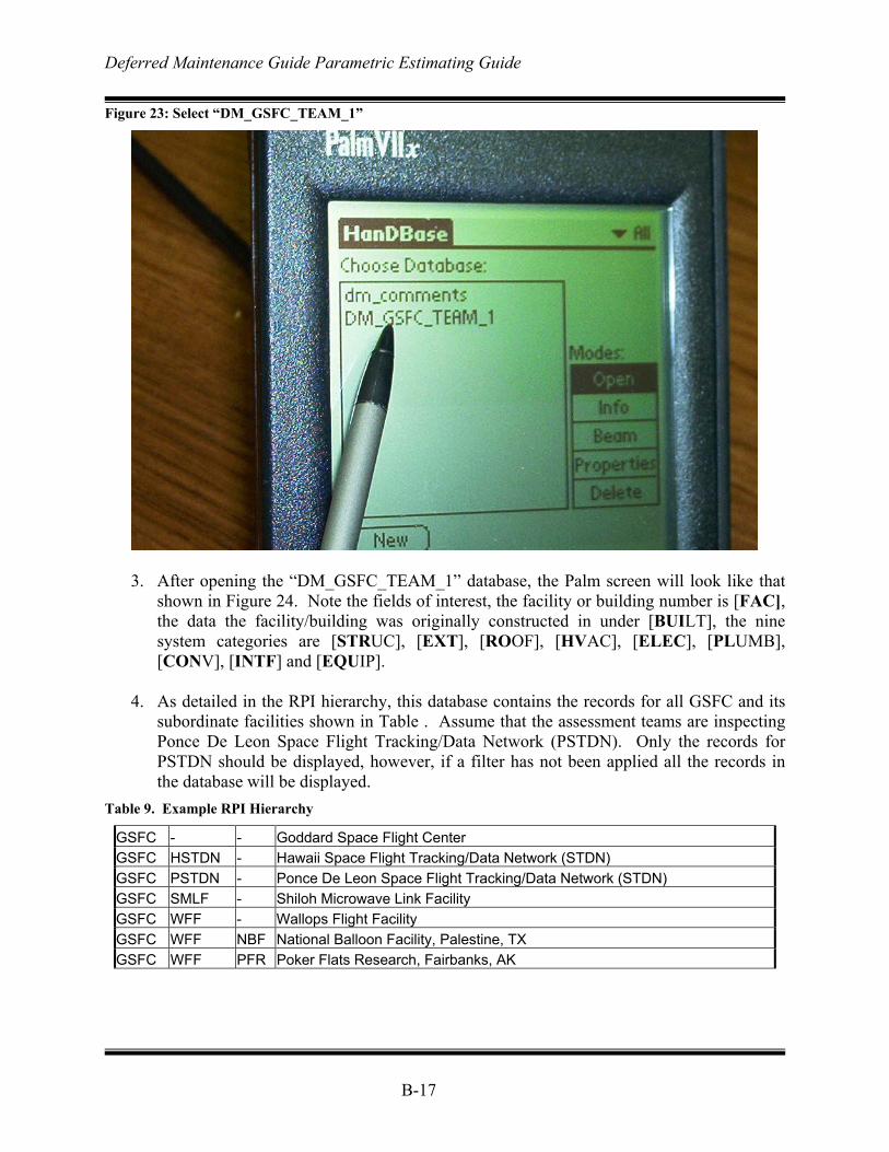
Deferred Maintenance Guide Parametric Estimating Guide
B-17
Figure 23: Select “DM_GSFC_TEAM_1”
3. After opening the “DM_GSFC_TEAM_1” database, the Palm screen will look like that
shown in Figure 24. Note the fields of interest, the facility or building number is [FAC], the data the facility/building was originally constructed in under [BUILT], the nine system categories are [STRUC], [EXT], [ROOF], [HVAC], [ELEC], [PLUMB], [CONV], [INTF] and [EQUIP].
4. As detailed in the RPI hierarchy, this database contains the records for all GSFC and its
subordinate facilities shown in Table . Assume that the assessment teams are inspecting Ponce De Leon Space Flight Tracking/Data Network (PSTDN). Only the records for PSTDN should be displayed, however, if a filter has not been applied all the records in the database will be displayed.
Table 9. Example RPI Hierarchy
GSFC - - Goddard Space Flight Center GSFC HSTDN - Hawaii Space Flight Tracking/Data Network (STDN) GSFC PSTDN - Ponce De Leon Space Flight Tracking/Data Network (STDN) GSFC SMLF - Shiloh Microwave Link Facility GSFC WFF - Wallops Flight Facility GSFC WFF NBF National Balloon Facility, Palestine, TX GSFC WFF PFR Poker Flats Research, Fairbanks, AK
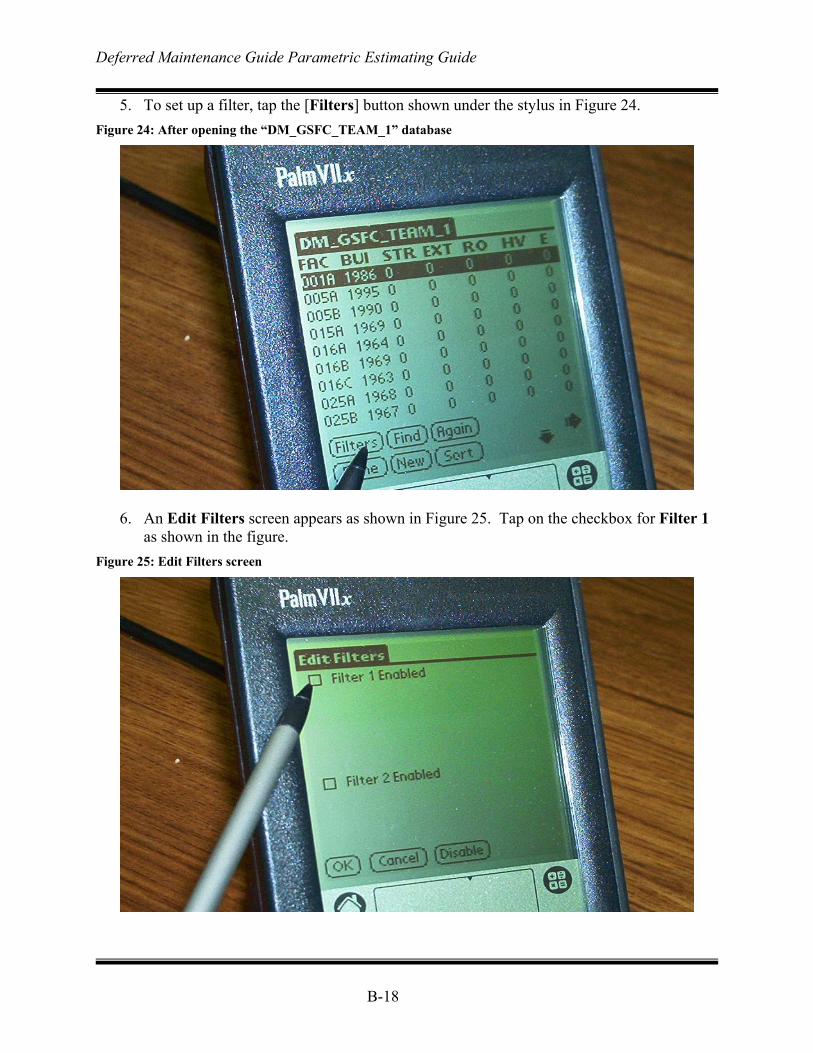
Deferred Maintenance Guide Parametric Estimating Guide
B-18
5. To set up a filter, tap the [Filters] button shown under the stylus in Figure 24. Figure 24: After opening the “DM_GSFC_TEAM_1” database
6. An Edit Filters screen appears as shown in Figure 25. Tap on the checkbox for Filter 1
as shown in the figure. Figure 25: Edit Filters screen
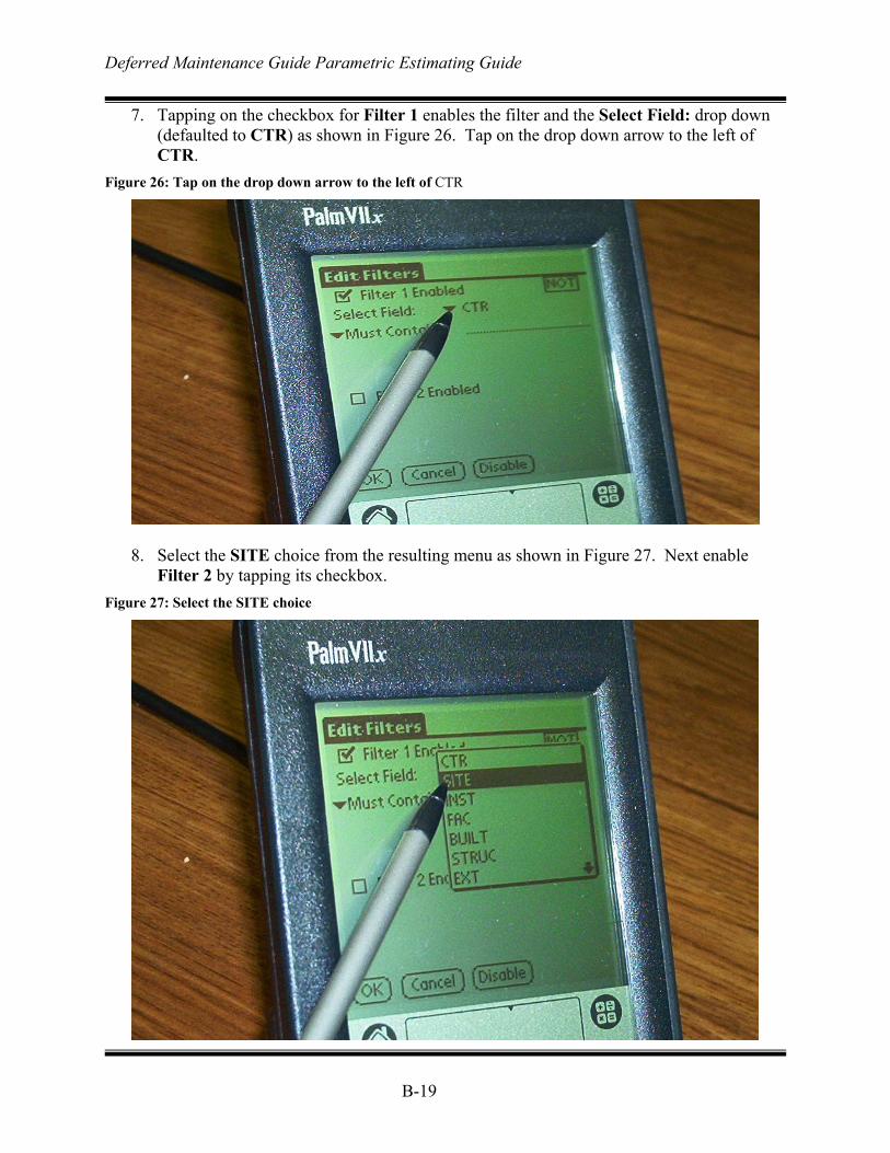
Deferred Maintenance Guide Parametric Estimating Guide
B-19
7. Tapping on the checkbox for Filter 1 enables the filter and the Select Field: drop down (defaulted to CTR) as shown in Figure 26. Tap on the drop down arrow to the left of CTR.
Figure 26: Tap on the drop down arrow to the left of CTR
8. Select the SITE choice from the resulting menu as shown in Figure 27. Next enable
Filter 2 by tapping its checkbox. Figure 27: Select the SITE choice
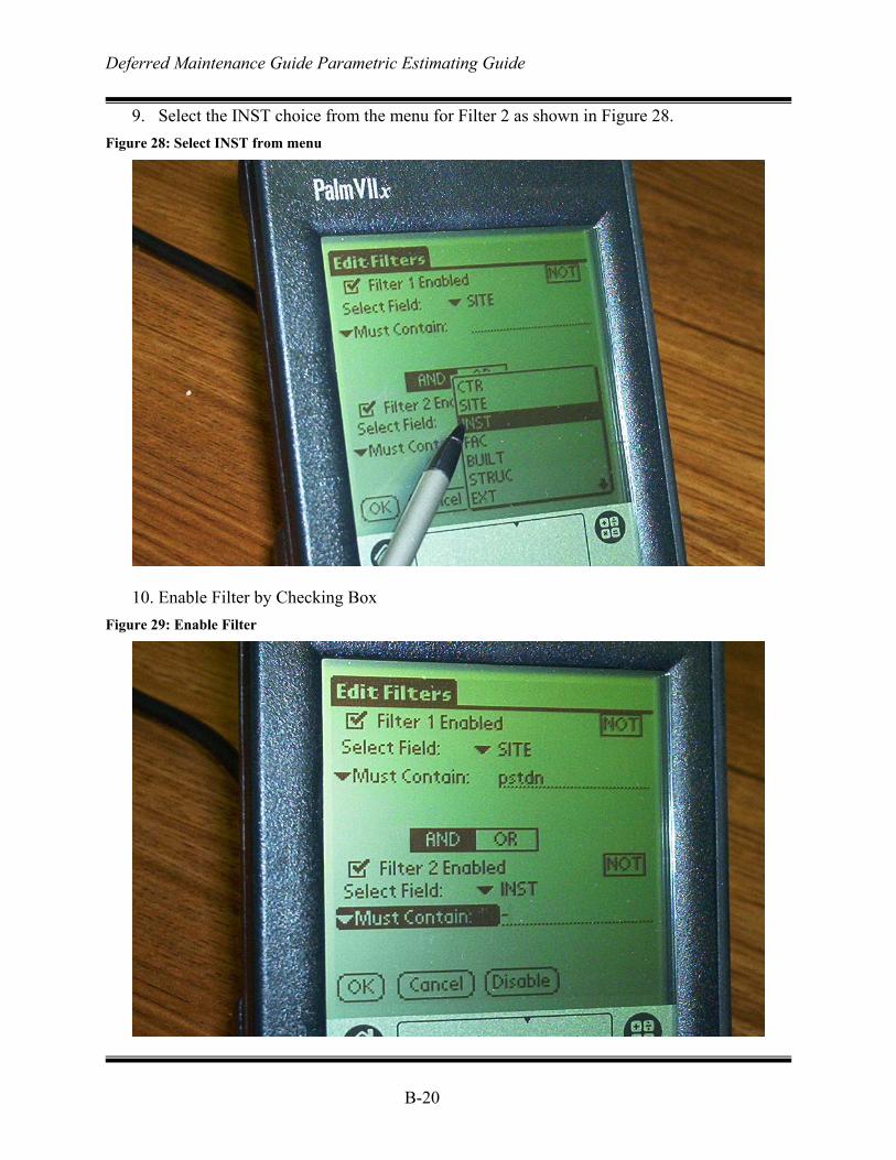
Deferred Maintenance Guide Parametric Estimating Guide
B-20
9. Select the INST choice from the menu for Filter 2 as shown in Figure 28. Figure 28: Select INST from menu
10. Enable Filter by Checking Box
Figure 29: Enable Filter
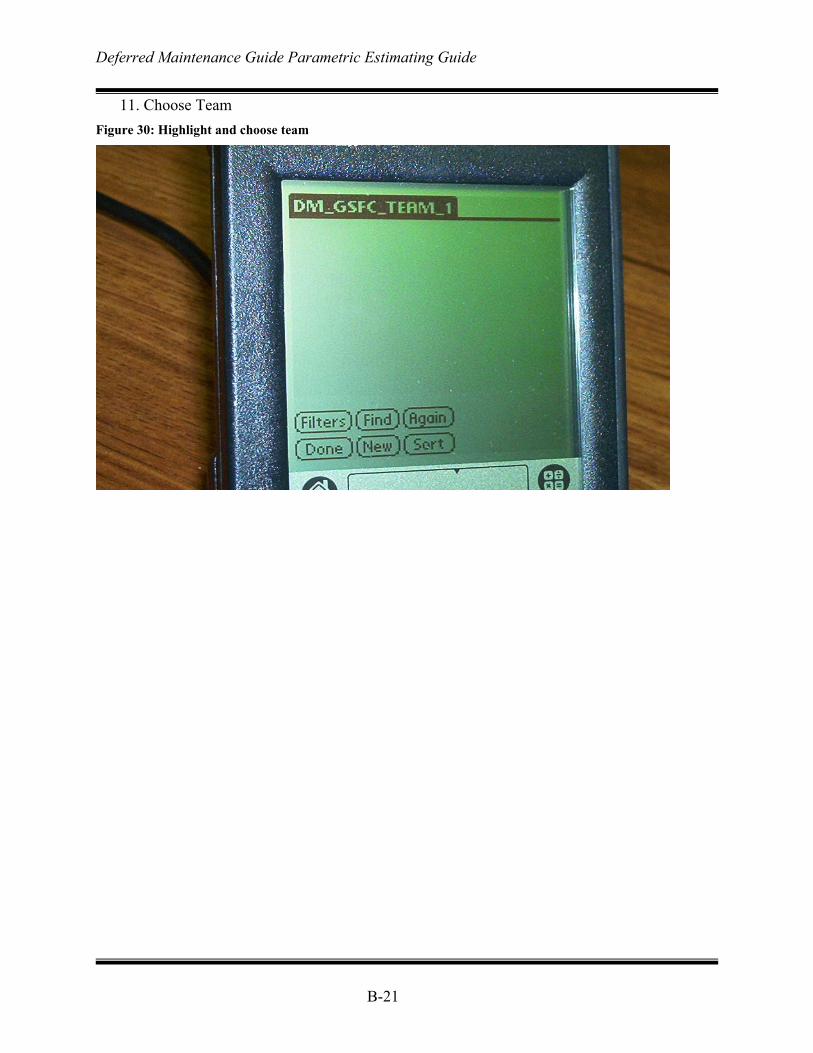
Deferred Maintenance Guide Parametric Estimating Guide
B-21
11. Choose Team Figure 30: Highlight and choose team
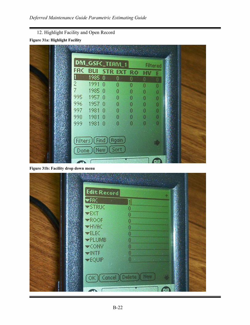
Deferred Maintenance Guide Parametric Estimating Guide
B-22
12. Highlight Facility and Open Record Figure 31a: Highlight Facility
Figure 31b: Facility drop down menu
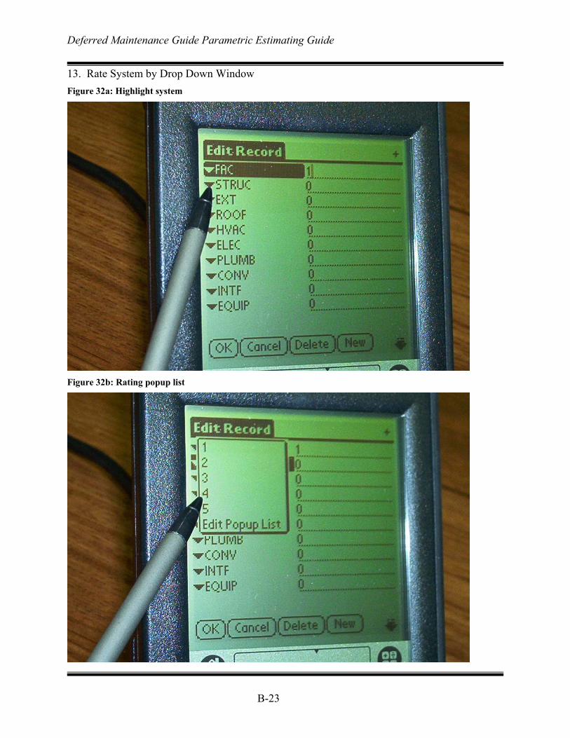
Deferred Maintenance Guide Parametric Estimating Guide
B-23
13. Rate System by Drop Down Window Figure 32a: Highlight system
Figure 32b: Rating popup list
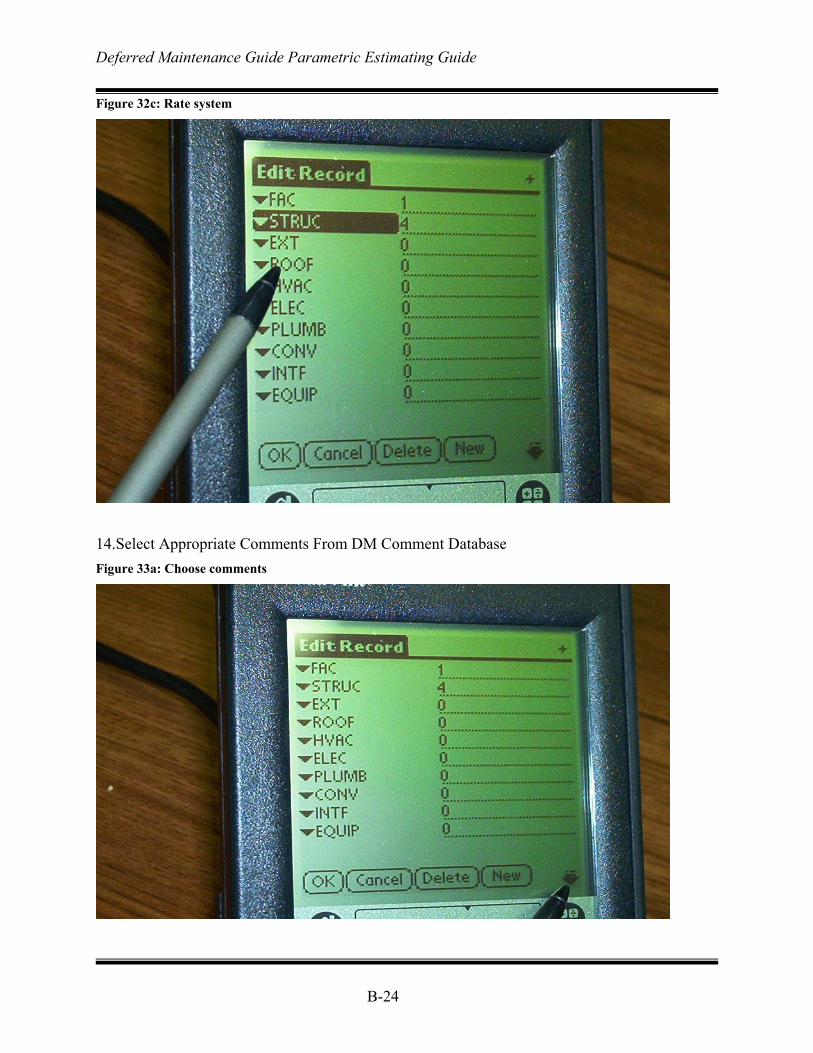
Deferred Maintenance Guide Parametric Estimating Guide
B-24
Figure 32c: Rate system
14.Select Appropriate Comments From DM Comment Database Figure 33a: Choose comments
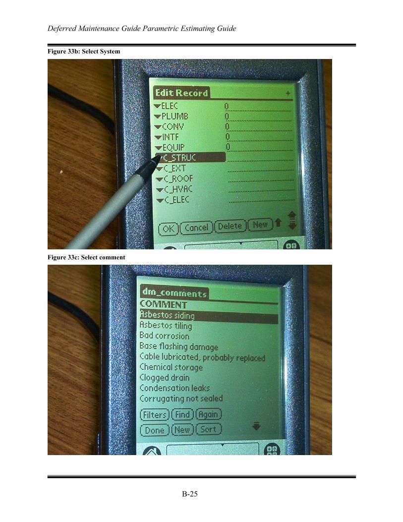
Deferred Maintenance Guide Parametric Estimating Guide
B-25
Figure 33b: Select System
Figure 33c: Select comment
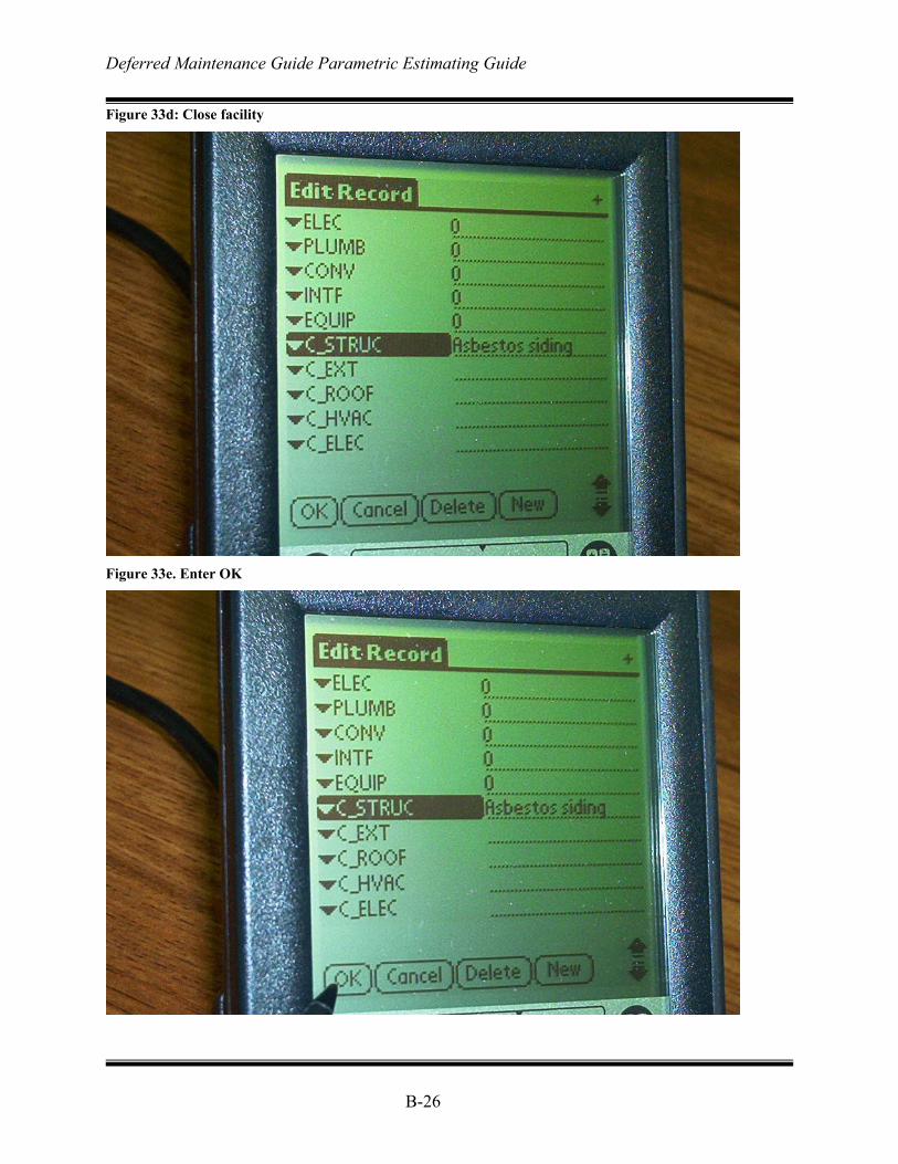
Deferred Maintenance Guide Parametric Estimating Guide
B-26
Figure 33d: Close facility
Figure 33e. Enter OK
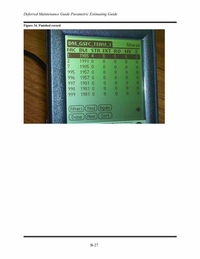
Deferred Maintenance Guide Parametric Estimating Guide
B-27
Figure 34. Finished record
Deferred Maintenance Guide Parametric Estimating Guide
B-28
Page intentionally left blank
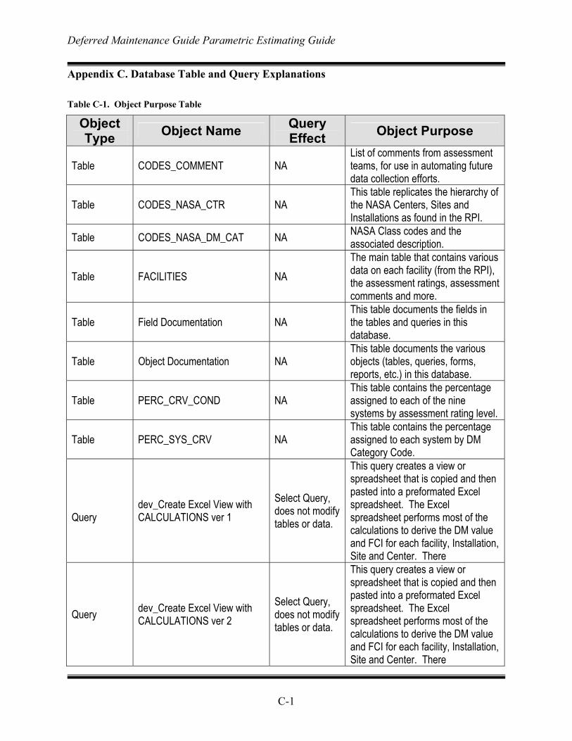
Deferred Maintenance Guide Parametric Estimating Guide
C-1
Appendix C. Database Table and Query Explanations Table C-1. Object Purpose Table
Object Type Object Name Query
Effect Object Purpose
Table CODES_COMMENT NA List of comments from assessment teams, for use in automating future data collection efforts.
Table CODES_NASA_CTR NA This table replicates the hierarchy of the NASA Centers, Sites and Installations as found in the RPI.
Table CODES_NASA_DM_CAT NA NASA Class codes and the associated description.
Table FACILITIES NA The main table that contains various data on each facility (from the RPI), the assessment ratings, assessment comments and more.
Table Field Documentation NA This table documents the fields in the tables and queries in this database.
Table Object Documentation NA This table documents the various objects (tables, queries, forms, reports, etc.) in this database.
Table PERC_CRV_COND NA This table contains the percentage assigned to each of the nine systems by assessment rating level.
Table PERC_SYS_CRV NA This table contains the percentage assigned to each system by DM Category Code.
Query
dev_Create Excel View with CALCULATIONS ver 1
Select Query, does not modify tables or data.
This query creates a view or spreadsheet that is copied and then pasted into a preformated Excel spreadsheet. The Excel spreadsheet performs most of the calculations to derive the DM value and FCI for each facility, Installation, Site and Center. There
Query dev_Create Excel View with CALCULATIONS ver 2
Select Query, does not modify tables or data.
This query creates a view or spreadsheet that is copied and then pasted into a preformated Excel spreadsheet. The Excel spreadsheet performs most of the calculations to derive the DM value and FCI for each facility, Installation, Site and Center. There
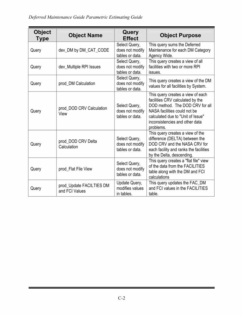
Deferred Maintenance Guide Parametric Estimating Guide
C-2
Object Type Object Name Query
Effect Object Purpose
Query dev_DM by DM_CAT_CODE Select Query, does not modify tables or data.
This query sums the Deferred Maintenance for each DM Category Agency Wide.
Query dev_Multiple RPI Issues Select Query, does not modify tables or data.
This query creates a view of all facilities with two or more RPI issues.
Query prod_DM Calculation Select Query, does not modify tables or data.
This query creates a view of the DM values for all facilities by System.
Query prod_DOD CRV Calculation View
Select Query, does not modify tables or data.
This query creates a view of each facilities CRV calculated by the DOD method. The DOD CRV for all NASA facilities could not be calculated due to "Unit of Issue" inconsistencies and other data problems.
Query prod_DOD CRV Delta Calculation
Select Query, does not modify tables or data.
This query creates a view of the difference (DELTA) between the DOD CRV and the NASA CRV for each facility and ranks the facilities by the Delta, descending.
Query prod_Flat File View Select Query, does not modify tables or data.
This query creates a "flat file" view of the data from the FACILITIES table along with the DM and FCI calculations
Query prod_Update FACILTIES DM and FCI Values
Update Query, modifies values in tables.
This query updates the FAC_DM and FCI values in the FACILITIES table.
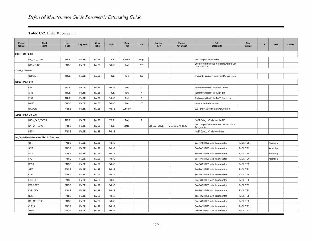
Deferred Maintenance Guide Parametric Estimating Guide
C-3
Table C-2. Field Document 1
Parent Object
Field Name
Key Field Required Allow
Nulls Index Data Type Size Foreign
Key Foreign
Key Object Field
Description Field
Source Total Sort Criteria
CODES_CAT_BLDG
DM_CAT_CODE TRUE FALSE FALSE TRUE Number Single DM Category Code Number
NASA_BLDG FALSE FALSE FALSE FALSE Text 255 Description of buildings or facilities with this DM Category Code
CODES_COMMENT
COMMENT TRUE FALSE FALSE TRUE Text 255 Frequently used comments from DM inspections
CODES_NASA_CTR
CTR TRUE FALSE FALSE FALSE Text 5 Text code to identify the NASA Center
SITE TRUE FALSE FALSE TRUE Text 7 Text code to identify the NASA Site
INST TRUE FALSE FALSE FALSE Text 7 Text code to identify the NASA Installation
NAME FALSE FALSE FALSE FALSE Text 100 Name of the NASA location
BMAR2001 FALSE FALSE FALSE FALSE Currency 2001 BMAR value for the NASA location
CODES_NASA_DM_CAT
NASA_CAT_CODES TRUE FALSE FALSE TRUE Text 7 NASA Category Code from the RPI
DM_CAT_CODE FALSE FALSE FALSE TRUE Single DM_CAT_CODE CODES_CAT_BLDG DM Category Code associated with this NASA Category Code
DESC FALSE FALSE FALSE FALSE NASA Category Code description
dev_Create Excel View with CALCULATIONS ver 1
CTR FALSE FALSE FALSE FALSE See FACILITIES table documentation FACILITIES Ascending
SITE FALSE FALSE FALSE FALSE See FACILITIES table documentation FACILITIES Ascending
INST FALSE FALSE FALSE FALSE See FACILITIES table documentation FACILITIES Ascending
FAC FALSE FALSE FALSE FALSE See FACILITIES table documentation FACILITIES Ascending
DESC FALSE FALSE FALSE FALSE See FACILITIES table documentation FACILITIES
STAT FALSE FALSE FALSE FALSE See FACILITIES table documentation FACILITIES
CRV FALSE FALSE FALSE FALSE See FACILITIES table documentation FACILITIES
EXCL_YR FALSE FALSE FALSE FALSE See FACILITIES table documentation FACILITIES
PERC_EXCL FALSE FALSE FALSE FALSE See FACILITIES table documentation FACILITIES
CAPACITY FALSE FALSE FALSE FALSE See FACILITIES table documentation FACILITIES
BUILT FALSE FALSE FALSE FALSE See FACILITIES table documentation FACILITIES
DM_CAT_CODE FALSE FALSE FALSE FALSE See FACILITIES table documentation FACILITIES
CLASS FALSE FALSE FALSE FALSE See FACILITIES table documentation FACILITIES
STRUC FALSE FALSE FALSE FALSE See FACILITIES table documentation FACILITIES
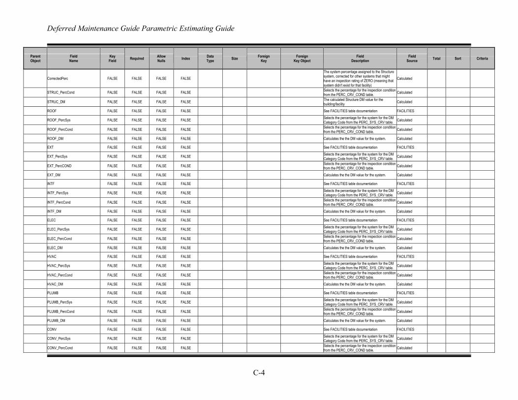
Deferred Maintenance Guide Parametric Estimating Guide
C-4
Parent Object
Field Name
Key Field Required Allow
Nulls Index Data Type Size Foreign
Key Foreign
Key Object Field
Description Field
Source Total Sort Criteria
CorrectedPerc FALSE FALSE FALSE FALSE The system percentage assigned to the Structure system, corrected for other systems that might have an inspection rating of ZERO (meaning that system didn't exist for that facility)
Calculated
STRUC_PercCond FALSE FALSE FALSE FALSE Selects the percentage for the inspection condition from the PERC_CRV_COND table. Calculated
STRUC_DM FALSE FALSE FALSE FALSE The calculated Structure DM value for the building/facility Calculated
ROOF FALSE FALSE FALSE FALSE See FACILITIES table documentation FACILITIES
ROOF_PercSys FALSE FALSE FALSE FALSE Selects the percentage for the system for the DM Category Code from the PERC_SYS_CRV table. Calculated
ROOF_PercCond FALSE FALSE FALSE FALSE Selects the percentage for the inspection condition from the PERC_CRV_COND table. Calculated
ROOF_DM FALSE FALSE FALSE FALSE Calculates the the DM value for the system. Calculated
EXT FALSE FALSE FALSE FALSE See FACILITIES table documentation FACILITIES
EXT_PercSys FALSE FALSE FALSE FALSE Selects the percentage for the system for the DM Category Code from the PERC_SYS_CRV table. Calculated
EXT_PercCOND FALSE FALSE FALSE FALSE Selects the percentage for the inspection condition from the PERC_CRV_COND table. Calculated
EXT_DM FALSE FALSE FALSE FALSE Calculates the the DM value for the system. Calculated
INTF FALSE FALSE FALSE FALSE See FACILITIES table documentation FACILITIES
INTF_PercSys FALSE FALSE FALSE FALSE Selects the percentage for the system for the DM Category Code from the PERC_SYS_CRV table. Calculated
INTF_PercCond FALSE FALSE FALSE FALSE Selects the percentage for the inspection condition from the PERC_CRV_COND table. Calculated
INTF_DM FALSE FALSE FALSE FALSE Calculates the the DM value for the system. Calculated
ELEC FALSE FALSE FALSE FALSE See FACILITIES table documentation FACILITIES
ELEC_PercSys FALSE FALSE FALSE FALSE Selects the percentage for the system for the DM Category Code from the PERC_SYS_CRV table. Calculated
ELEC_PercCond FALSE FALSE FALSE FALSE Selects the percentage for the inspection condition from the PERC_CRV_COND table. Calculated
ELEC_DM FALSE FALSE FALSE FALSE Calculates the the DM value for the system. Calculated
HVAC FALSE FALSE FALSE FALSE See FACILITIES table documentation FACILITIES
HVAC_PercSys FALSE FALSE FALSE FALSE Selects the percentage for the system for the DM Category Code from the PERC_SYS_CRV table. Calculated
HVAC_PercCond FALSE FALSE FALSE FALSE Selects the percentage for the inspection condition from the PERC_CRV_COND table. Calculated
HVAC_DM FALSE FALSE FALSE FALSE Calculates the the DM value for the system. Calculated
PLUMB FALSE FALSE FALSE FALSE See FACILITIES table documentation FACILITIES
PLUMB_PercSys FALSE FALSE FALSE FALSE Selects the percentage for the system for the DM Category Code from the PERC_SYS_CRV table. Calculated
PLUMB_PercCond FALSE FALSE FALSE FALSE Selects the percentage for the inspection condition from the PERC_CRV_COND table. Calculated
PLUMB_DM FALSE FALSE FALSE FALSE Calculates the the DM value for the system. Calculated
CONV FALSE FALSE FALSE FALSE See FACILITIES table documentation FACILITIES
CONV_PercSys FALSE FALSE FALSE FALSE Selects the percentage for the system for the DM Category Code from the PERC_SYS_CRV table. Calculated
CONV_PercCond FALSE FALSE FALSE FALSE Selects the percentage for the inspection condition from the PERC_CRV_COND table. Calculated
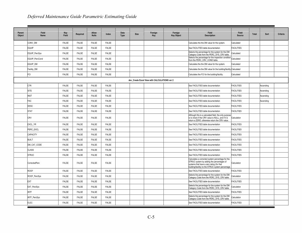
Deferred Maintenance Guide Parametric Estimating Guide
C-5
Parent Object
Field Name
Key Field Required Allow
Nulls Index Data Type Size Foreign
Key Foreign
Key Object Field
Description Field
Source Total Sort Criteria
CONV_DM FALSE FALSE FALSE FALSE Calculates the the DM value for the system. Calculated
EQUIP FALSE FALSE FALSE FALSE See FACILITIES table documentation FACILITIES
EQUIP_PercSys FALSE FALSE FALSE FALSE Selects the percentage for the system for the DM Category Code from the PERC_SYS_CRV table. Calculated
EQUIP_PercCond FALSE FALSE FALSE FALSE Selects the percentage for the inspection condition from the PERC_CRV_COND table. Calculated
EQUIP_DM FALSE FALSE FALSE FALSE Calculates the the DM value for the system. Calculated
Facility_DM FALSE FALSE FALSE FALSE Calculates the the DM value for the building/facility.Calculated
FCI FALSE FALSE FALSE FALSE Calculates the FCI for the building/facility. Calculated
dev_Create Excel View with CALCULATIONS ver 2
CTR FALSE FALSE FALSE FALSE See FACILITIES table documentation FACILITIES Ascending
SITE FALSE FALSE FALSE FALSE See FACILITIES table documentation FACILITIES Ascending
INST FALSE FALSE FALSE FALSE See FACILITIES table documentation FACILITIES Ascending
FAC FALSE FALSE FALSE FALSE See FACILITIES table documentation FACILITIES Ascending
DESC FALSE FALSE FALSE FALSE See FACILITIES table documentation FACILITIES
STAT FALSE FALSE FALSE FALSE See FACILITIES table documentation FACILITIES
CRV FALSE FALSE FALSE FALSE Although this is a calculated field, the only purpose is to check if the CRV value is NULL, and if it is return a ZERO, otherwise return the CRV value.
Calculation
EXCL_YR FALSE FALSE FALSE FALSE See FACILITIES table documentation FACILITIES
PERC_EXCL FALSE FALSE FALSE FALSE See FACILITIES table documentation FACILITIES
CAPACITY FALSE FALSE FALSE FALSE See FACILITIES table documentation FACILITIES
BUILT FALSE FALSE FALSE FALSE See FACILITIES table documentation FACILITIES
DM_CAT_CODE FALSE FALSE FALSE FALSE See FACILITIES table documentation FACILITIES
CLASS FALSE FALSE FALSE FALSE See FACILITIES table documentation FACILITIES
STRUC FALSE FALSE FALSE FALSE See FACILITIES table documentation FACILITIES
CorrectedPerc FALSE FALSE FALSE FALSE Calculates a corrected system percentage for the STRUC system by adding the percentages of systems that have a zero rating (for that building/facility) to the STRUC system percentage.
Calculation
ROOF FALSE FALSE FALSE FALSE See FACILITIES table documentation FACILITIES
ROOF_PercSys FALSE FALSE FALSE FALSE Selects the percentage for the system for the DM Category Code from the PERC_SYS_CRV table. Calculation
EXT FALSE FALSE FALSE FALSE See FACILITIES table documentation FACILITIES
EXT_PercSys FALSE FALSE FALSE FALSE Selects the percentage for the system for the DM Category Code from the PERC_SYS_CRV table. Calculation
INTF FALSE FALSE FALSE FALSE See FACILITIES table documentation FACILITIES
INTF_PercSys FALSE FALSE FALSE FALSE Selects the percentage for the system for the DM Category Code from the PERC_SYS_CRV table. Calculation
ELEC FALSE FALSE FALSE FALSE See FACILITIES table documentation FACILITIES
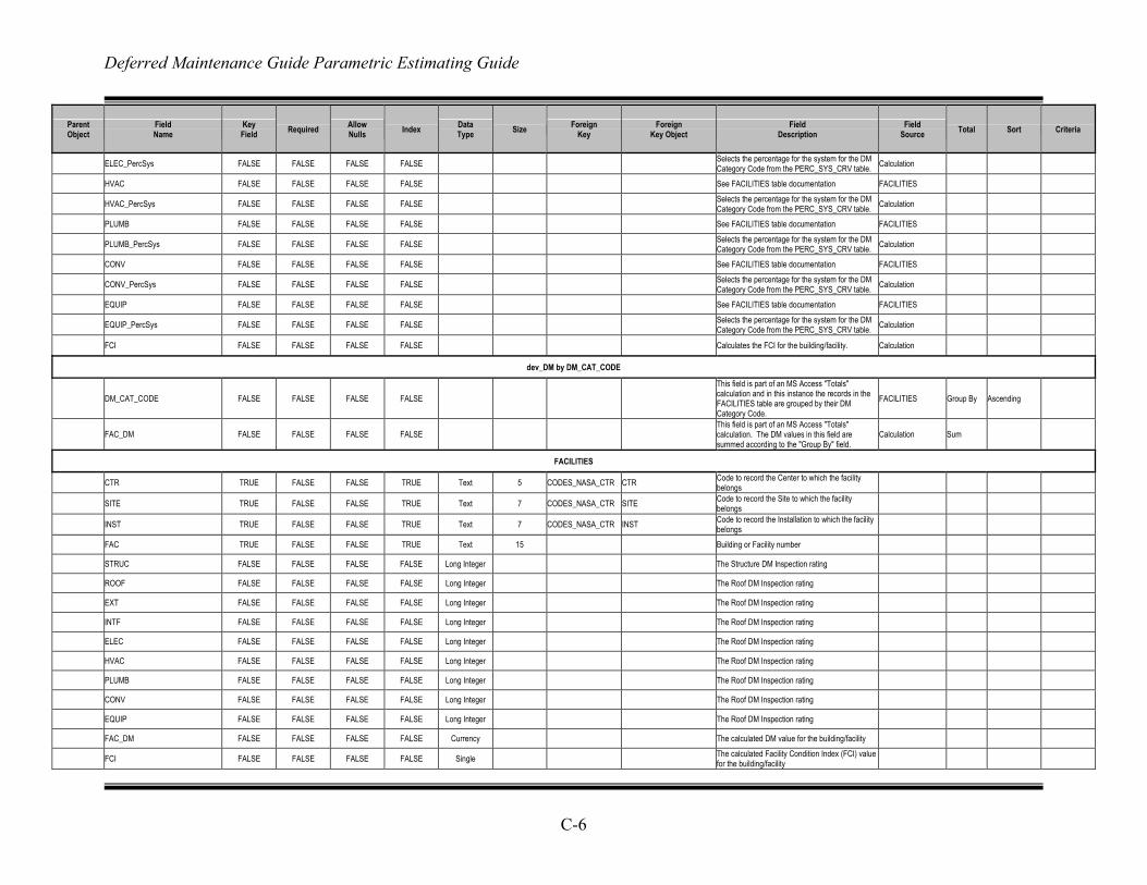
Deferred Maintenance Guide Parametric Estimating Guide
C-6
Parent Object
Field Name
Key Field Required Allow
Nulls Index Data Type Size Foreign
Key Foreign
Key Object Field
Description Field
Source Total Sort Criteria
ELEC_PercSys FALSE FALSE FALSE FALSE Selects the percentage for the system for the DM Category Code from the PERC_SYS_CRV table. Calculation
HVAC FALSE FALSE FALSE FALSE See FACILITIES table documentation FACILITIES
HVAC_PercSys FALSE FALSE FALSE FALSE Selects the percentage for the system for the DM Category Code from the PERC_SYS_CRV table. Calculation
PLUMB FALSE FALSE FALSE FALSE See FACILITIES table documentation FACILITIES
PLUMB_PercSys FALSE FALSE FALSE FALSE Selects the percentage for the system for the DM Category Code from the PERC_SYS_CRV table. Calculation
CONV FALSE FALSE FALSE FALSE See FACILITIES table documentation FACILITIES
CONV_PercSys FALSE FALSE FALSE FALSE Selects the percentage for the system for the DM Category Code from the PERC_SYS_CRV table. Calculation
EQUIP FALSE FALSE FALSE FALSE See FACILITIES table documentation FACILITIES
EQUIP_PercSys FALSE FALSE FALSE FALSE Selects the percentage for the system for the DM Category Code from the PERC_SYS_CRV table. Calculation
FCI FALSE FALSE FALSE FALSE Calculates the FCI for the building/facility. Calculation
dev_DM by DM_CAT_CODE
DM_CAT_CODE FALSE FALSE FALSE FALSE This field is part of an MS Access "Totals" calculation and in this instance the records in the FACILITIES table are grouped by their DM Category Code.
FACILITIES Group By Ascending
FAC_DM FALSE FALSE FALSE FALSE This field is part of an MS Access "Totals" calculation. The DM values in this field are summed according to the "Group By" field.
Calculation Sum
FACILITIES
CTR TRUE FALSE FALSE TRUE Text 5 CODES_NASA_CTR CTR Code to record the Center to which the facility belongs
SITE TRUE FALSE FALSE TRUE Text 7 CODES_NASA_CTR SITE Code to record the Site to which the facility belongs
INST TRUE FALSE FALSE TRUE Text 7 CODES_NASA_CTR INST Code to record the Installation to which the facility belongs
FAC TRUE FALSE FALSE TRUE Text 15 Building or Facility number
STRUC FALSE FALSE FALSE FALSE Long Integer The Structure DM Inspection rating
ROOF FALSE FALSE FALSE FALSE Long Integer The Roof DM Inspection rating
EXT FALSE FALSE FALSE FALSE Long Integer The Roof DM Inspection rating
INTF FALSE FALSE FALSE FALSE Long Integer The Roof DM Inspection rating
ELEC FALSE FALSE FALSE FALSE Long Integer The Roof DM Inspection rating
HVAC FALSE FALSE FALSE FALSE Long Integer The Roof DM Inspection rating
PLUMB FALSE FALSE FALSE FALSE Long Integer The Roof DM Inspection rating
CONV FALSE FALSE FALSE FALSE Long Integer The Roof DM Inspection rating
EQUIP FALSE FALSE FALSE FALSE Long Integer The Roof DM Inspection rating
FAC_DM FALSE FALSE FALSE FALSE Currency The calculated DM value for the building/facility
FCI FALSE FALSE FALSE FALSE Single The calculated Facility Condition Index (FCI) value for the building/facility
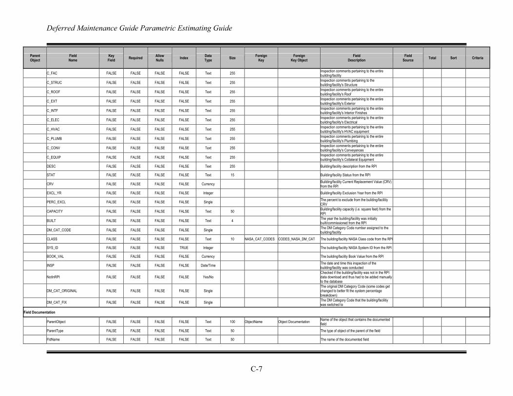
Deferred Maintenance Guide Parametric Estimating Guide
C-7
Parent Object
Field Name
Key Field Required Allow
Nulls Index Data Type Size Foreign
Key Foreign
Key Object Field
Description Field
Source Total Sort Criteria
C_FAC FALSE FALSE FALSE FALSE Text 255 Inspection comments pertaining to the entire building/facility
C_STRUC FALSE FALSE FALSE FALSE Text 255 Inspection comments pertaining to the building/facility's Structure
C_ROOF FALSE FALSE FALSE FALSE Text 255 Inspection comments pertaining to the entire building/facility's Roof
C_EXT FALSE FALSE FALSE FALSE Text 255 Inspection comments pertaining to the entire building/facility's Exterior
C_INTF FALSE FALSE FALSE FALSE Text 255 Inspection comments pertaining to the entire building/facility's Interior Finishes
C_ELEC FALSE FALSE FALSE FALSE Text 255 Inspection comments pertaining to the entire building/facility's Electrical
C_HVAC FALSE FALSE FALSE FALSE Text 255 Inspection comments pertaining to the entire building/facility's HVAC equipment
C_PLUMB FALSE FALSE FALSE FALSE Text 255 Inspection comments pertaining to the entire building/facility's Plumbing
C_CONV FALSE FALSE FALSE FALSE Text 255 Inspection comments pertaining to the entire building/facility's Conveyances
C_EQUIP FALSE FALSE FALSE FALSE Text 255 Inspection comments pertaining to the entire building/facility's Collateral Equipment
DESC FALSE FALSE FALSE FALSE Text 255 Building/facility description from the RPI
STAT FALSE FALSE FALSE FALSE Text 15 Building/facility Status from the RPI
CRV FALSE FALSE FALSE FALSE Currency Building/facility Current Replacement Value (CRV) from the RPI
EXCL_YR FALSE FALSE FALSE FALSE Integer Building/facility Exclusion Year from the RPI
PERC_EXCL FALSE FALSE FALSE FALSE Single The percent to exclude from the building/facilitiy CRV
CAPACITY FALSE FALSE FALSE FALSE Text 50 Building/facility capacity (i.e. square feet) from the RPI
BUILT FALSE FALSE FALSE FALSE Text 4 The year the building/facility was initially built/commissioned from the RPI
DM_CAT_CODE FALSE FALSE FALSE FALSE Single The DM Category Code number assigned to the building/facility
CLASS FALSE FALSE FALSE FALSE Text 10 NASA_CAT_CODES CODES_NASA_DM_CAT The building/facility NASA Class code from the RPI
SYS_ID FALSE FALSE FALSE TRUE Integer The building/facility NASA System ID from the RPI
BOOK_VAL FALSE FALSE FALSE FALSE Currency The building/facility Book Value from the RPI
INSP FALSE FALSE FALSE FALSE Date/Time The date and time this inspection of the building/facility was conducted
NotInRPI FALSE FALSE FALSE FALSE Yes/No Checked if the building/facility was not in the RPI data download and thus had to be added manually to the database
DM_CAT_ORIGINAL FALSE FALSE FALSE FALSE Single The original DM Category Code (some codes get changed to better fit the system percentage breakdown)
DM_CAT_FIX FALSE FALSE FALSE FALSE Single The DM Category Code that the building/facilitiy was switched to
Field Documentation
ParentObject FALSE FALSE FALSE FALSE Text 100 ObjectName Object Documentation Name of the object that contains the documented field
ParentType FALSE FALSE FALSE FALSE Text 50 The type of object of the parent of the field
FldName FALSE FALSE FALSE FALSE Text 50 The name of the documented field
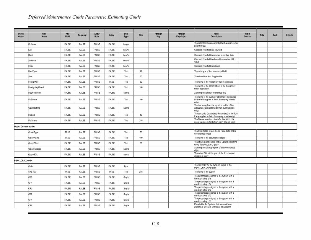
Deferred Maintenance Guide Parametric Estimating Guide
C-8
Parent Object
Field Name
Key Field Required Allow
Nulls Index Data Type Size Foreign
Key Foreign
Key Object Field
Description Field
Source Total Sort Criteria
FldOrder FALSE FALSE FALSE FALSE Integer The order that the documented field appears in the parent object
Key FALSE FALSE FALSE FALSE Yes/No Checked if the field is a key field
Reqd FALSE FALSE FALSE FALSE Yes/No Checked if the field is required to contain data
AllowNull FALSE FALSE FALSE FALSE Yes/No Checked if the field is allowed to contain a NULL value
Index FALSE FALSE FALSE FALSE Yes/No Checked if the field is indexed
DataType FALSE FALSE FALSE FALSE Text 12 The data type of the documented field
Size FALSE FALSE FALSE FALSE Text 50 The size of the field if applicable
ForeignKey FALSE FALSE FALSE TRUE Text 50 The name of the foreign key field if applicable
ForeignKeyObject FALSE FALSE FALSE FALSE Text 100 The name of the parent object of the foreign key field if applicable
FldDescription FALSE FALSE FALSE FALSE Memo A description of the documented field
FldSource FALSE FALSE FALSE FALSE Text 100 The name of the query or table that is the source for the field (applies to fields from query objects only)
CalcFldString FALSE FALSE FALSE FALSE Memo The text string from the equation builder of the calculation (applies to fields from query objects only)
FldSort FALSE FALSE FALSE FALSE Text 10 The sort order (ascending, descending) of the field if any (applies to fields from query objects only)
FldCriteria FALSE FALSE FALSE FALSE Text 255 The filter or selection criteria for this field in the query (applies to fields from query objects only)
Object Documentation
ObjectType TRUE FALSE FALSE FALSE Text 50 The type (Table, Query, Form, Report etc) of the documented object
ObjectName TRUE FALSE FALSE FALSE Text 100 The name of the documented object
QueryEffect FALSE FALSE FALSE FALSE Text 50 The effect (Select, Make Table, Update etc) of the query if the object is a query
ObjectPurpose FALSE FALSE FALSE FALSE Memo A description of the purpose of the documented object
QuerySQL FALSE FALSE FALSE FALSE Memo The actual SQL of the query if the documented object is a query
PERC_CRV_COND
Order FALSE FALSE FALSE FALSE Byte The sort order for the systems shown in the PERC_CRV_COND table
SYSTEM TRUE FALSE FALSE TRUE Text 255 The name of the system
CR5 FALSE FALSE FALSE FALSE Single The percentage assigned to the system with a condition rating of 5
CR4 FALSE FALSE FALSE FALSE Single The percentage assigned to the system with a condition rating of 4
CR3 FALSE FALSE FALSE FALSE Single The percentage assigned to the system with a condition rating of 3
CR2 FALSE FALSE FALSE FALSE Single The percentage assigned to the system with a condition rating of 2
CR1 FALSE FALSE FALSE FALSE Single The percentage assigned to the system with a condition rating of 1
CR0 FALSE FALSE FALSE FALSE Single Placeholder for Systems that have not been inspected, prevents erroneous calculations
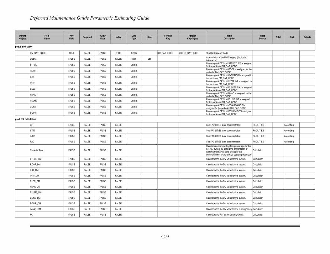
Deferred Maintenance Guide Parametric Estimating Guide
C-9
Parent Object
Field Name
Key Field Required Allow
Nulls Index Data Type Size Foreign
Key Foreign
Key Object Field
Description Field
Source Total Sort Criteria
PERC_SYS_CRV
DM_CAT_CODE TRUE FALSE FALSE TRUE Single DM_CAT_CODE CODES_CAT_BLDG The DM Category Code
DESC FALSE FALSE FALSE FALSE Text 255 A description of the DM Category (duplicated information)
STRUC FALSE FALSE FALSE FALSE Double Percentage of CRV that STRUCTURE is assigned for the particular DM_CAT_CODE
ROOF FALSE FALSE FALSE FALSE Double Percentage of CRV that ROOF is assigned for the particular DM_CAT_CODE
EXT FALSE FALSE FALSE FALSE Double Percentage of CRV that EXTERIOR is assigned forthe particular DM_CAT_CODE
INTF FALSE FALSE FALSE FALSE Double Percentage of CRV that INTERIOR is assigned for the particular DM_CAT_CODE
ELEC FALSE FALSE FALSE FALSE Double Percentage of CRV that ELECTRICAL is assigned for the particular DM_CAT_CODE
HVAC FALSE FALSE FALSE FALSE Double Percentage of CRV that HVAC is assigned for the particular DM_CAT_CODE
PLUMB FALSE FALSE FALSE FALSE Double Percentage of CRV that PLUMBING is assigned for the particular DM_CAT_CODE
CONV FALSE FALSE FALSE FALSE Double Percentage of CRV that CONVEYANCE is assigned for the particular DM_CAT_CODE
EQUIP FALSE FALSE FALSE FALSE Double Percentage of CRV that EQUIPMENT is assigned for the particular DM_CAT_CODE
prod_DM Calculation
CTR FALSE FALSE FALSE FALSE See FACILITIES table documentation FACILITIES Ascending
SITE FALSE FALSE FALSE FALSE See FACILITIES table documentation FACILITIES Ascending
INST FALSE FALSE FALSE FALSE See FACILITIES table documentation FACILITIES Ascending
FAC FALSE FALSE FALSE FALSE See FACILITIES table documentation FACILITIES Ascending
CorrectedPerc FALSE FALSE FALSE FALSE Calculates a corrected system percentage for the STRUC system by adding the percentages of systems that have a zero rating (for that building/facility) to the STRUC system percentage.
Calculation
STRUC_DM FALSE FALSE FALSE FALSE Calculates the the DM value for the system. Calculation
ROOF_DM FALSE FALSE FALSE FALSE Calculates the the DM value for the system. Calculation
EXT_DM FALSE FALSE FALSE FALSE Calculates the the DM value for the system. Calculation
INTF_DM FALSE FALSE FALSE FALSE Calculates the the DM value for the system. Calculation
ELEC_DM FALSE FALSE FALSE FALSE Calculates the the DM value for the system. Calculation
HVAC_DM FALSE FALSE FALSE FALSE Calculates the the DM value for the system. Calculation
PLUMB_DM FALSE FALSE FALSE FALSE Calculates the the DM value for the system. Calculation
CONV_DM FALSE FALSE FALSE FALSE Calculates the the DM value for the system. Calculation
EQUIP_DM FALSE FALSE FALSE FALSE Calculates the the DM value for the system. Calculation
Facility_DM FALSE FALSE FALSE FALSE Calculates the the DM value for the building/facility.Calculation
FCI FALSE FALSE FALSE FALSE Calculates the FCI for the building/facility. Calculation
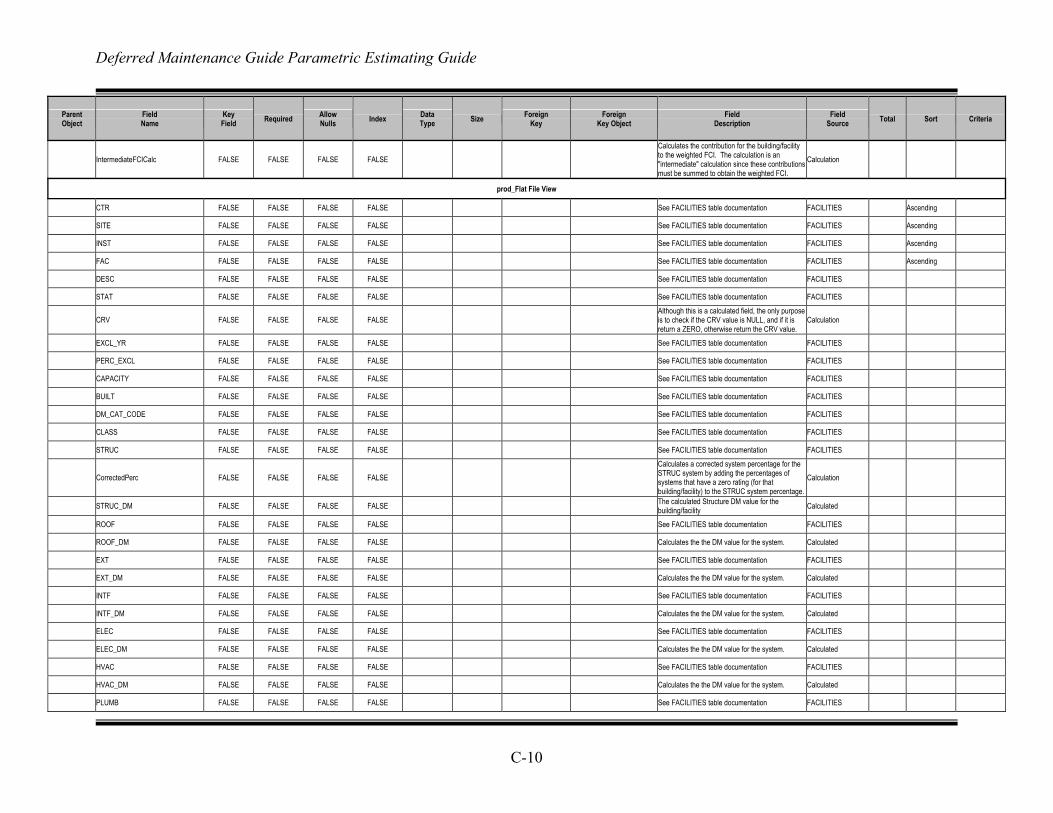
Deferred Maintenance Guide Parametric Estimating Guide
C-10
Parent Object
Field Name
Key Field Required Allow
Nulls Index Data Type Size Foreign
Key Foreign
Key Object Field
Description Field
Source Total Sort Criteria
IntermediateFCICalc FALSE FALSE FALSE FALSE Calculates the contribution for the building/facility to the weighted FCI. The calculation is an "intermediate" calculation since these contributions must be summed to obtain the weighted FCI.
Calculation
prod_Flat File View
CTR FALSE FALSE FALSE FALSE See FACILITIES table documentation FACILITIES Ascending
SITE FALSE FALSE FALSE FALSE See FACILITIES table documentation FACILITIES Ascending
INST FALSE FALSE FALSE FALSE See FACILITIES table documentation FACILITIES Ascending
FAC FALSE FALSE FALSE FALSE See FACILITIES table documentation FACILITIES Ascending
DESC FALSE FALSE FALSE FALSE See FACILITIES table documentation FACILITIES
STAT FALSE FALSE FALSE FALSE See FACILITIES table documentation FACILITIES
CRV FALSE FALSE FALSE FALSE Although this is a calculated field, the only purpose is to check if the CRV value is NULL, and if it is return a ZERO, otherwise return the CRV value.
Calculation
EXCL_YR FALSE FALSE FALSE FALSE See FACILITIES table documentation FACILITIES
PERC_EXCL FALSE FALSE FALSE FALSE See FACILITIES table documentation FACILITIES
CAPACITY FALSE FALSE FALSE FALSE See FACILITIES table documentation FACILITIES
BUILT FALSE FALSE FALSE FALSE See FACILITIES table documentation FACILITIES
DM_CAT_CODE FALSE FALSE FALSE FALSE See FACILITIES table documentation FACILITIES
CLASS FALSE FALSE FALSE FALSE See FACILITIES table documentation FACILITIES
STRUC FALSE FALSE FALSE FALSE See FACILITIES table documentation FACILITIES
CorrectedPerc FALSE FALSE FALSE FALSE Calculates a corrected system percentage for the STRUC system by adding the percentages of systems that have a zero rating (for that building/facility) to the STRUC system percentage.
Calculation
STRUC_DM FALSE FALSE FALSE FALSE The calculated Structure DM value for the building/facility Calculated
ROOF FALSE FALSE FALSE FALSE See FACILITIES table documentation FACILITIES
ROOF_DM FALSE FALSE FALSE FALSE Calculates the the DM value for the system. Calculated
EXT FALSE FALSE FALSE FALSE See FACILITIES table documentation FACILITIES
EXT_DM FALSE FALSE FALSE FALSE Calculates the the DM value for the system. Calculated
INTF FALSE FALSE FALSE FALSE See FACILITIES table documentation FACILITIES
INTF_DM FALSE FALSE FALSE FALSE Calculates the the DM value for the system. Calculated
ELEC FALSE FALSE FALSE FALSE See FACILITIES table documentation FACILITIES
ELEC_DM FALSE FALSE FALSE FALSE Calculates the the DM value for the system. Calculated
HVAC FALSE FALSE FALSE FALSE See FACILITIES table documentation FACILITIES
HVAC_DM FALSE FALSE FALSE FALSE Calculates the the DM value for the system. Calculated
PLUMB FALSE FALSE FALSE FALSE See FACILITIES table documentation FACILITIES
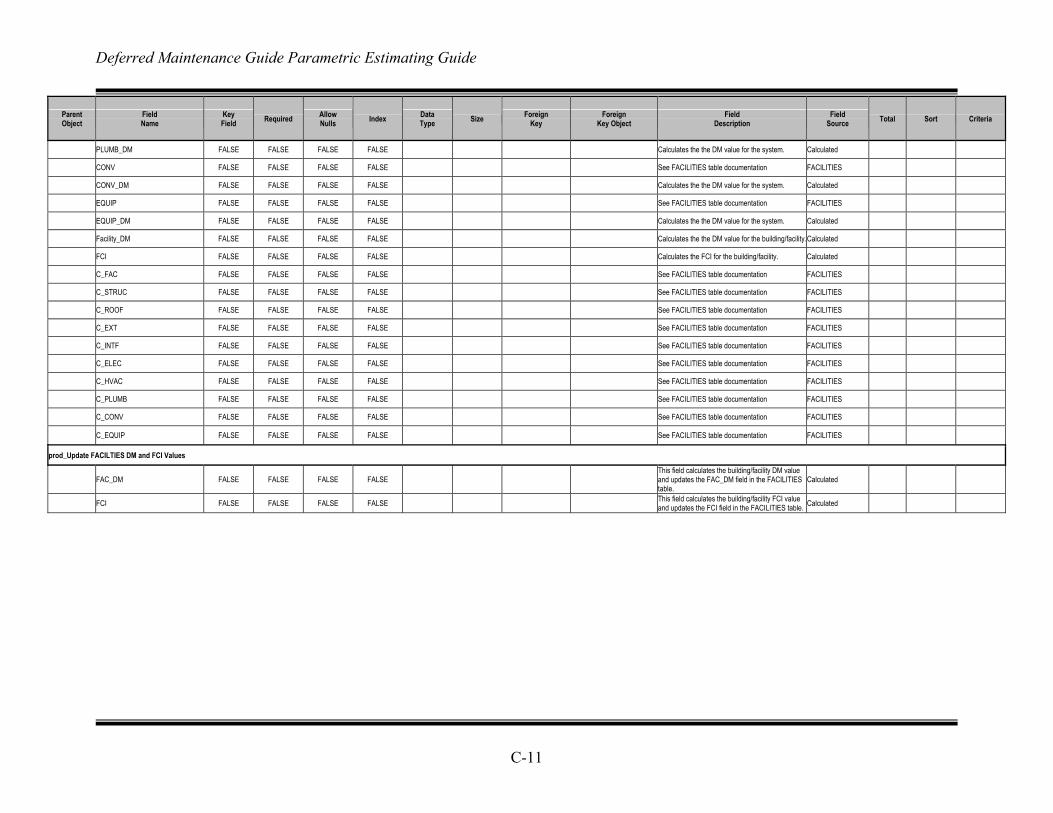
Deferred Maintenance Guide Parametric Estimating Guide
C-11
Parent Object
Field Name
Key Field Required Allow
Nulls Index Data Type Size Foreign
Key Foreign
Key Object Field
Description Field
Source Total Sort Criteria
PLUMB_DM FALSE FALSE FALSE FALSE Calculates the the DM value for the system. Calculated
CONV FALSE FALSE FALSE FALSE See FACILITIES table documentation FACILITIES
CONV_DM FALSE FALSE FALSE FALSE Calculates the the DM value for the system. Calculated
EQUIP FALSE FALSE FALSE FALSE See FACILITIES table documentation FACILITIES
EQUIP_DM FALSE FALSE FALSE FALSE Calculates the the DM value for the system. Calculated
Facility_DM FALSE FALSE FALSE FALSE Calculates the the DM value for the building/facility.Calculated
FCI FALSE FALSE FALSE FALSE Calculates the FCI for the building/facility. Calculated
C_FAC FALSE FALSE FALSE FALSE See FACILITIES table documentation FACILITIES
C_STRUC FALSE FALSE FALSE FALSE See FACILITIES table documentation FACILITIES
C_ROOF FALSE FALSE FALSE FALSE See FACILITIES table documentation FACILITIES
C_EXT FALSE FALSE FALSE FALSE See FACILITIES table documentation FACILITIES
C_INTF FALSE FALSE FALSE FALSE See FACILITIES table documentation FACILITIES
C_ELEC FALSE FALSE FALSE FALSE See FACILITIES table documentation FACILITIES
C_HVAC FALSE FALSE FALSE FALSE See FACILITIES table documentation FACILITIES
C_PLUMB FALSE FALSE FALSE FALSE See FACILITIES table documentation FACILITIES
C_CONV FALSE FALSE FALSE FALSE See FACILITIES table documentation FACILITIES
C_EQUIP FALSE FALSE FALSE FALSE See FACILITIES table documentation FACILITIES
prod_Update FACILTIES DM and FCI Values
FAC_DM FALSE FALSE FALSE FALSE This field calculates the building/facility DM value and updates the FAC_DM field in the FACILITIES table.
Calculated
FCI FALSE FALSE FALSE FALSE This field calculates the building/facility FCI value and updates the FCI field in the FACILITIES table. Calculated
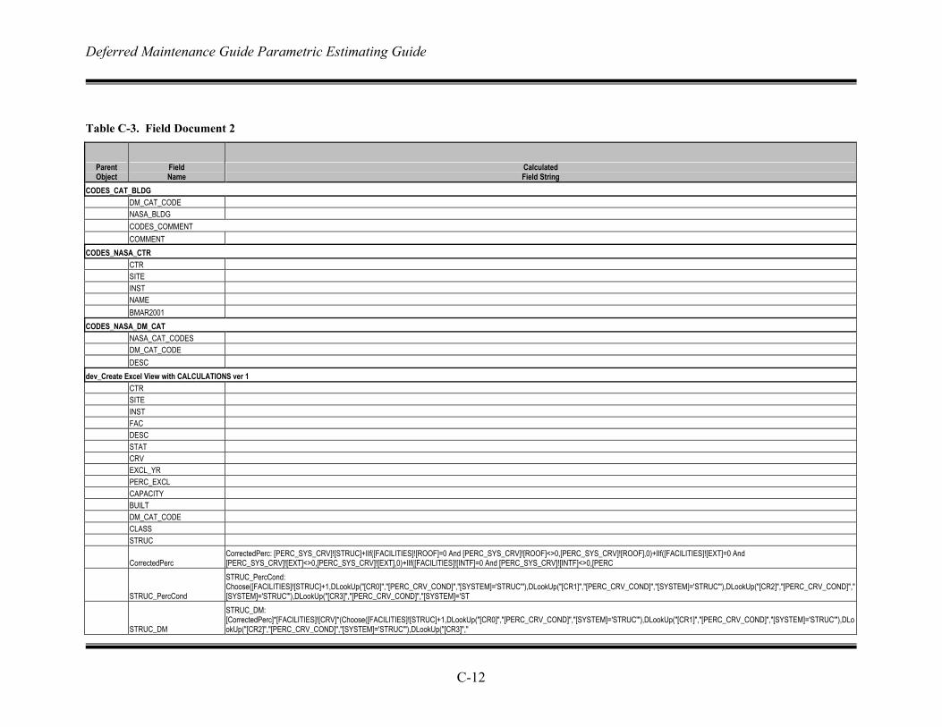
Deferred Maintenance Guide Parametric Estimating Guide
C-12
Table C-3. Field Document 2
Parent Object
Field Name
Calculated Field String
CODES_CAT_BLDG DM_CAT_CODE NASA_BLDG CODES_COMMENT COMMENT CODES_NASA_CTR CTR SITE INST NAME BMAR2001 CODES_NASA_DM_CAT NASA_CAT_CODES DM_CAT_CODE DESC dev_Create Excel View with CALCULATIONS ver 1 CTR SITE INST FAC DESC STAT CRV EXCL_YR PERC_EXCL CAPACITY BUILT DM_CAT_CODE CLASS STRUC
CorrectedPerc CorrectedPerc: [PERC_SYS_CRV]![STRUC]+IIf([FACILITIES]![ROOF]=0 And [PERC_SYS_CRV]![ROOF]<>0,[PERC_SYS_CRV]![ROOF],0)+IIf([FACILITIES]![EXT]=0 And [PERC_SYS_CRV]![EXT]<>0,[PERC_SYS_CRV]![EXT],0)+IIf([FACILITIES]![INTF]=0 And [PERC_SYS_CRV]![INTF]<>0,[PERC
STRUC_PercCond
STRUC_PercCond: Choose([FACILITIES]![STRUC]+1,DLookUp("[CR0]","[PERC_CRV_COND]","[SYSTEM]='STRUC'"),DLookUp("[CR1]","[PERC_CRV_COND]","[SYSTEM]='STRUC'"),DLookUp("[CR2]","[PERC_CRV_COND]","[SYSTEM]='STRUC'"),DLookUp("[CR3]","[PERC_CRV_COND]","[SYSTEM]='ST
STRUC_DM
STRUC_DM: [CorrectedPerc]*[FACILITIES]![CRV]*(Choose([FACILITIES]![STRUC]+1,DLookUp("[CR0]","[PERC_CRV_COND]","[SYSTEM]='STRUC'"),DLookUp("[CR1]","[PERC_CRV_COND]","[SYSTEM]='STRUC'"),DLookUp("[CR2]","[PERC_CRV_COND]","[SYSTEM]='STRUC'"),DLookUp("[CR3]","
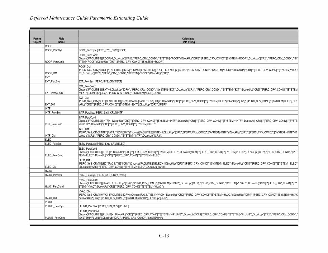
Deferred Maintenance Guide Parametric Estimating Guide
C-13
Parent Object
Field Name
Calculated Field String
ROOF ROOF_PercSys ROOF_PercSys: [PERC_SYS_CRV]![ROOF]
ROOF_PercCond
ROOF_PercCond: Choose([FACILITIES]![ROOF]+1,DLookUp("[CR0]","[PERC_CRV_COND]","[SYSTEM]='ROOF'"),DLookUp("[CR1]","[PERC_CRV_COND]","[SYSTEM]='ROOF'"),DLookUp("[CR2]","[PERC_CRV_COND]","[SYSTEM]='ROOF'"),DLookUp("[CR3]","[PERC_CRV_COND]","[SYSTEM]='ROOF'")
ROOF_DM
ROOF_DM: [PERC_SYS_CRV]![ROOF]*[FACILITIES]![CRV]*(Choose([FACILITIES]![ROOF]+1,DLookUp("[CR0]","[PERC_CRV_COND]","[SYSTEM]='ROOF'"),DLookUp("[CR1]","[PERC_CRV_COND]","[SYSTEM]='ROOF'"),DLookUp("[CR2]","[PERC_CRV_COND]","[SYSTEM]='ROOF'"),DLookUp("[CR3]",
EXT EXT_PercSys EXT_PercSys: [PERC_SYS_CRV]![EXT]
EXT_PercCOND
EXT_PercCond: Choose([FACILITIES]![EXT]+1,DLookUp("[CR0]","[PERC_CRV_COND]","[SYSTEM]='EXT'"),DLookUp("[CR1]","[PERC_CRV_COND]","[SYSTEM]='EXT'"),DLookUp("[CR2]","[PERC_CRV_COND]","[SYSTEM]='EXT'"),DLookUp("[CR3]","[PERC_CRV_COND]","[SYSTEM]='EXT'"),DLook
EXT_DM
EXT_DM: [PERC_SYS_CRV]![EXT]*[FACILITIES]![CRV]*(Choose([FACILITIES]![EXT]+1,DLookUp("[CR0]","[PERC_CRV_COND]","[SYSTEM]='EXT'"),DLookUp("[CR1]","[PERC_CRV_COND]","[SYSTEM]='EXT'"),DLookUp("[CR2]","[PERC_CRV_COND]","[SYSTEM]='EXT'"),DLookUp("[CR3]","[PERC
INTF INTF_PercSys INTF_PercSys: [PERC_SYS_CRV]![INTF]
INTF_PercCond
INTF_PercCond: Choose([FACILITIES]![INTF]+1,DLookUp("[CR0]","[PERC_CRV_COND]","[SYSTEM]='INTF'"),DLookUp("[CR1]","[PERC_CRV_COND]","[SYSTEM]='INTF'"),DLookUp("[CR2]","[PERC_CRV_COND]","[SYSTEM]='INTF'"),DLookUp("[CR3]","[PERC_CRV_COND]","[SYSTEM]='INTF'")
INTF_DM
INTF_DM: [PERC_SYS_CRV]![INTF]*[FACILITIES]![CRV]*(Choose([FACILITIES]![INTF]+1,DLookUp("[CR0]","[PERC_CRV_COND]","[SYSTEM]='INTF'"),DLookUp("[CR1]","[PERC_CRV_COND]","[SYSTEM]='INTF'"),DLookUp("[CR2]","[PERC_CRV_COND]","[SYSTEM]='INTF'"),DLookUp("[CR3]",
ELEC ELEC_PercSys ELEC_PercSys: [PERC_SYS_CRV]![ELEC]
ELEC_PercCond
ELEC_PercCond: Choose([FACILITIES]![ELEC]+1,DLookUp("[CR0]","[PERC_CRV_COND]","[SYSTEM]='ELEC'"),DLookUp("[CR1]","[PERC_CRV_COND]","[SYSTEM]='ELEC'"),DLookUp("[CR2]","[PERC_CRV_COND]","[SYSTEM]='ELEC'"),DLookUp("[CR3]","[PERC_CRV_COND]","[SYSTEM]='ELEC'")
ELEC_DM
ELEC_DM: [PERC_SYS_CRV]![ELEC]*[FACILITIES]![CRV]*(Choose([FACILITIES]![ELEC]+1,DLookUp("[CR0]","[PERC_CRV_COND]","[SYSTEM]='ELEC'"),DLookUp("[CR1]","[PERC_CRV_COND]","[SYSTEM]='ELEC'"),DLookUp("[CR2]","[PERC_CRV_COND]","[SYSTEM]='ELEC'"),DLookUp("[CR3]",
HVAC HVAC_PercSys HVAC_PercSys: [PERC_SYS_CRV]![HVAC]
HVAC_PercCond
HVAC_PercCond: Choose([FACILITIES]![HVAC]+1,DLookUp("[CR0]","[PERC_CRV_COND]","[SYSTEM]='HVAC'"),DLookUp("[CR1]","[PERC_CRV_COND]","[SYSTEM]='HVAC'"),DLookUp("[CR2]","[PERC_CRV_COND]","[SYSTEM]='HVAC'"),DLookUp("[CR3]","[PERC_CRV_COND]","[SYSTEM]='HVAC'")
HVAC_DM
HVAC_DM: [PERC_SYS_CRV]![HVAC]*[FACILITIES]![CRV]*(Choose([FACILITIES]![HVAC]+1,DLookUp("[CR0]","[PERC_CRV_COND]","[SYSTEM]='HVAC'"),DLookUp("[CR1]","[PERC_CRV_COND]","[SYSTEM]='HVAC'"),DLookUp("[CR2]","[PERC_CRV_COND]","[SYSTEM]='HVAC'"),DLookUp("[CR3]",
PLUMB PLUMB_PercSys PLUMB_PercSys: [PERC_SYS_CRV]![PLUMB]
PLUMB_PercCond
PLUMB_PercCond: Choose([FACILITIES]![PLUMB]+1,DLookUp("[CR0]","[PERC_CRV_COND]","[SYSTEM]='PLUMB'"),DLookUp("[CR1]","[PERC_CRV_COND]","[SYSTEM]='PLUMB'"),DLookUp("[CR2]","[PERC_CRV_COND]","[SYSTEM]='PLUMB'"),DLookUp("[CR3]","[PERC_CRV_COND]","[SYSTEM]='PL
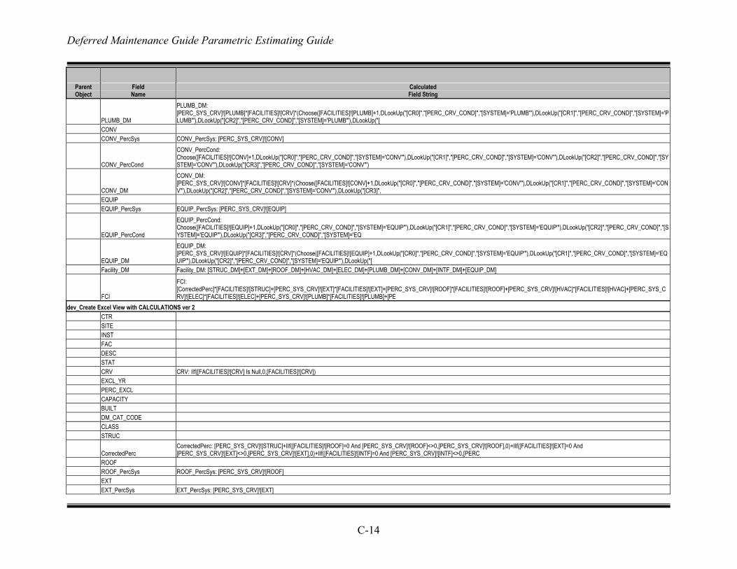
Deferred Maintenance Guide Parametric Estimating Guide
C-14
Parent Object
Field Name
Calculated Field String
PLUMB_DM
PLUMB_DM: [PERC_SYS_CRV]![PLUMB]*[FACILITIES]![CRV]*(Choose([FACILITIES]![PLUMB]+1,DLookUp("[CR0]","[PERC_CRV_COND]","[SYSTEM]='PLUMB'"),DLookUp("[CR1]","[PERC_CRV_COND]","[SYSTEM]='PLUMB'"),DLookUp("[CR2]","[PERC_CRV_COND]","[SYSTEM]='PLUMB'"),DLookUp("[
CONV CONV_PercSys CONV_PercSys: [PERC_SYS_CRV]![CONV]
CONV_PercCond
CONV_PercCond: Choose([FACILITIES]![CONV]+1,DLookUp("[CR0]","[PERC_CRV_COND]","[SYSTEM]='CONV'"),DLookUp("[CR1]","[PERC_CRV_COND]","[SYSTEM]='CONV'"),DLookUp("[CR2]","[PERC_CRV_COND]","[SYSTEM]='CONV'"),DLookUp("[CR3]","[PERC_CRV_COND]","[SYSTEM]='CONV'")
CONV_DM
CONV_DM: [PERC_SYS_CRV]![CONV]*[FACILITIES]![CRV]*(Choose([FACILITIES]![CONV]+1,DLookUp("[CR0]","[PERC_CRV_COND]","[SYSTEM]='CONV'"),DLookUp("[CR1]","[PERC_CRV_COND]","[SYSTEM]='CONV'"),DLookUp("[CR2]","[PERC_CRV_COND]","[SYSTEM]='CONV'"),DLookUp("[CR3]",
EQUIP EQUIP_PercSys EQUIP_PercSys: [PERC_SYS_CRV]![EQUIP]
EQUIP_PercCond
EQUIP_PercCond: Choose([FACILITIES]![EQUIP]+1,DLookUp("[CR0]","[PERC_CRV_COND]","[SYSTEM]='EQUIP'"),DLookUp("[CR1]","[PERC_CRV_COND]","[SYSTEM]='EQUIP'"),DLookUp("[CR2]","[PERC_CRV_COND]","[SYSTEM]='EQUIP'"),DLookUp("[CR3]","[PERC_CRV_COND]","[SYSTEM]='EQ
EQUIP_DM
EQUIP_DM: [PERC_SYS_CRV]![EQUIP]*[FACILITIES]![CRV]*(Choose([FACILITIES]![EQUIP]+1,DLookUp("[CR0]","[PERC_CRV_COND]","[SYSTEM]='EQUIP'"),DLookUp("[CR1]","[PERC_CRV_COND]","[SYSTEM]='EQUIP'"),DLookUp("[CR2]","[PERC_CRV_COND]","[SYSTEM]='EQUIP'"),DLookUp("[
Facility_DM Facility_DM: [STRUC_DM]+[EXT_DM]+[ROOF_DM]+[HVAC_DM]+[ELEC_DM]+[PLUMB_DM]+[CONV_DM]+[INTF_DM]+[EQUIP_DM]
FCI
FCI: [CorrectedPerc]*[FACILITIES]![STRUC]+[PERC_SYS_CRV]![EXT]*[FACILITIES]![EXT]+[PERC_SYS_CRV]![ROOF]*[FACILITIES]![ROOF]+[PERC_SYS_CRV]![HVAC]*[FACILITIES]![HVAC]+[PERC_SYS_CRV]![ELEC]*[FACILITIES]![ELEC]+[PERC_SYS_CRV]![PLUMB]*[FACILITIES]![PLUMB]+[PE
dev_Create Excel View with CALCULATIONS ver 2 CTR SITE INST FAC DESC STAT CRV CRV: IIf([FACILITIES]![CRV] Is Null,0,[FACILITIES]![CRV]) EXCL_YR PERC_EXCL CAPACITY BUILT DM_CAT_CODE CLASS STRUC
CorrectedPerc CorrectedPerc: [PERC_SYS_CRV]![STRUC]+IIf([FACILITIES]![ROOF]=0 And [PERC_SYS_CRV]![ROOF]<>0,[PERC_SYS_CRV]![ROOF],0)+IIf([FACILITIES]![EXT]=0 And [PERC_SYS_CRV]![EXT]<>0,[PERC_SYS_CRV]![EXT],0)+IIf([FACILITIES]![INTF]=0 And [PERC_SYS_CRV]![INTF]<>0,[PERC
ROOF ROOF_PercSys ROOF_PercSys: [PERC_SYS_CRV]![ROOF] EXT EXT_PercSys EXT_PercSys: [PERC_SYS_CRV]![EXT]
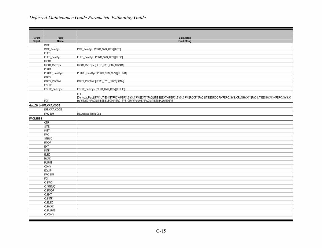
Deferred Maintenance Guide Parametric Estimating Guide
C-15
Parent Object
Field Name
Calculated Field String
INTF INTF_PercSys INTF_PercSys: [PERC_SYS_CRV]![INTF] ELEC ELEC_PercSys ELEC_PercSys: [PERC_SYS_CRV]![ELEC] HVAC HVAC_PercSys HVAC_PercSys: [PERC_SYS_CRV]![HVAC] PLUMB PLUMB_PercSys PLUMB_PercSys: [PERC_SYS_CRV]![PLUMB] CONV CONV_PercSys CONV_PercSys: [PERC_SYS_CRV]![CONV] EQUIP EQUIP_PercSys EQUIP_PercSys: [PERC_SYS_CRV]![EQUIP]
FCI
FCI: [CorrectedPerc]*[FACILITIES]![STRUC]+[PERC_SYS_CRV]![EXT]*[FACILITIES]![EXT]+[PERC_SYS_CRV]![ROOF]*[FACILITIES]![ROOF]+[PERC_SYS_CRV]![HVAC]*[FACILITIES]![HVAC]+[PERC_SYS_CRV]![ELEC]*[FACILITIES]![ELEC]+[PERC_SYS_CRV]![PLUMB]*[FACILITIES]![PLUMB]+[PE
dev_DM by DM_CAT_CODE DM_CAT_CODE FAC_DM MS Access Totals Calc FACILITIES CTR SITE INST FAC STRUC ROOF EXT INTF ELEC HVAC PLUMB CONV EQUIP FAC_DM FCI C_FAC C_STRUC C_ROOF C_EXT C_INTF C_ELEC C_HVAC C_PLUMB C_CONV

Deferred Maintenance Guide Parametric Estimating Guide
C-16
Parent Object
Field Name
Calculated Field String
C_EQUIP DESC STAT CRV EXCL_YR PERC_EXCL CAPACITY BUILT DM_CAT_CODE CLASS SYS_ID BOOK_VAL INSP NotInRPI DM_CAT_ORIGINAL DM_CAT_FIX Field Documentation ParentObject ParentType FldName FldOrder Key Reqd AllowNull Index DataType Size ForeignKey ForeignKeyObject FldDescription FldSource CalcFldString FldSort FldCriteria Object Documentation ObjectType ObjectName QueryEffect ObjectPurpose QuerySQL PERC_CRV_COND Order SYSTEM
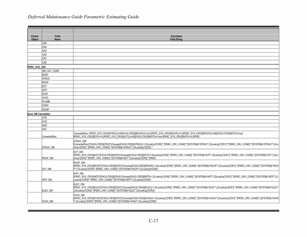
Deferred Maintenance Guide Parametric Estimating Guide
C-17
Parent Object
Field Name
Calculated Field String
CR5 CR4 CR3 CR2 CR1 CR0 PERC_SYS_CRV DM_CAT_CODE DESC STRUC ROOF EXT INTF ELEC HVAC PLUMB CONV EQUIP prod_DM Calculation CTR SITE INST FAC
CorrectedPerc CorrectedPerc: [PERC_SYS_CRV]![STRUC]+IIf([FACILITIES]![ROOF]=0 And [PERC_SYS_CRV]![ROOF]<>0,[PERC_SYS_CRV]![ROOF],0)+IIf([FACILITIES]![EXT]=0 And [PERC_SYS_CRV]![EXT]<>0,[PERC_SYS_CRV]![EXT],0)+IIf([FACILITIES]![INTF]=0 And [PERC_SYS_CRV]![INTF]<>0,[PERC
STRUC_DM
STRUC_DM: [CorrectedPerc]*[FACILITIES]![CRV]*(Choose([FACILITIES]![STRUC]+1,DLookUp("[CR0]","[PERC_CRV_COND]","[SYSTEM]='STRUC'"),DLookUp("[CR1]","[PERC_CRV_COND]","[SYSTEM]='STRUC'"),DLookUp("[CR2]","[PERC_CRV_COND]","[SYSTEM]='STRUC'"),DLookUp("[CR3]","
ROOF_DM
EXT_DM: [PERC_SYS_CRV]![EXT]*[FACILITIES]![CRV]*(Choose([FACILITIES]![EXT]+1,DLookUp("[CR0]","[PERC_CRV_COND]","[SYSTEM]='EXT'"),DLookUp("[CR1]","[PERC_CRV_COND]","[SYSTEM]='EXT'"),DLookUp("[CR2]","[PERC_CRV_COND]","[SYSTEM]='EXT'"),DLookUp("[CR3]","[PERC
EXT_DM
ROOF_DM: [PERC_SYS_CRV]![ROOF]*[FACILITIES]![CRV]*(Choose([FACILITIES]![ROOF]+1,DLookUp("[CR0]","[PERC_CRV_COND]","[SYSTEM]='ROOF'"),DLookUp("[CR1]","[PERC_CRV_COND]","[SYSTEM]='ROOF'"),DLookUp("[CR2]","[PERC_CRV_COND]","[SYSTEM]='ROOF'"),DLookUp("[CR3]",
INTF_DM
INTF_DM: [PERC_SYS_CRV]![INTF]*[FACILITIES]![CRV]*(Choose([FACILITIES]![INTF]+1,DLookUp("[CR0]","[PERC_CRV_COND]","[SYSTEM]='INTF'"),DLookUp("[CR1]","[PERC_CRV_COND]","[SYSTEM]='INTF'"),DLookUp("[CR2]","[PERC_CRV_COND]","[SYSTEM]='INTF'"),DLookUp("[CR3]",
ELEC_DM
ELEC_DM: [PERC_SYS_CRV]![ELEC]*[FACILITIES]![CRV]*(Choose([FACILITIES]![ELEC]+1,DLookUp("[CR0]","[PERC_CRV_COND]","[SYSTEM]='ELEC'"),DLookUp("[CR1]","[PERC_CRV_COND]","[SYSTEM]='ELEC'"),DLookUp("[CR2]","[PERC_CRV_COND]","[SYSTEM]='ELEC'"),DLookUp("[CR3]",
HVAC_DM
HVAC_DM: [PERC_SYS_CRV]![HVAC]*[FACILITIES]![CRV]*(Choose([FACILITIES]![HVAC]+1,DLookUp("[CR0]","[PERC_CRV_COND]","[SYSTEM]='HVAC'"),DLookUp("[CR1]","[PERC_CRV_COND]","[SYSTEM]='HVAC'"),DLookUp("[CR2]","[PERC_CRV_COND]","[SYSTEM]='HVAC'"),DLookUp("[CR3]",
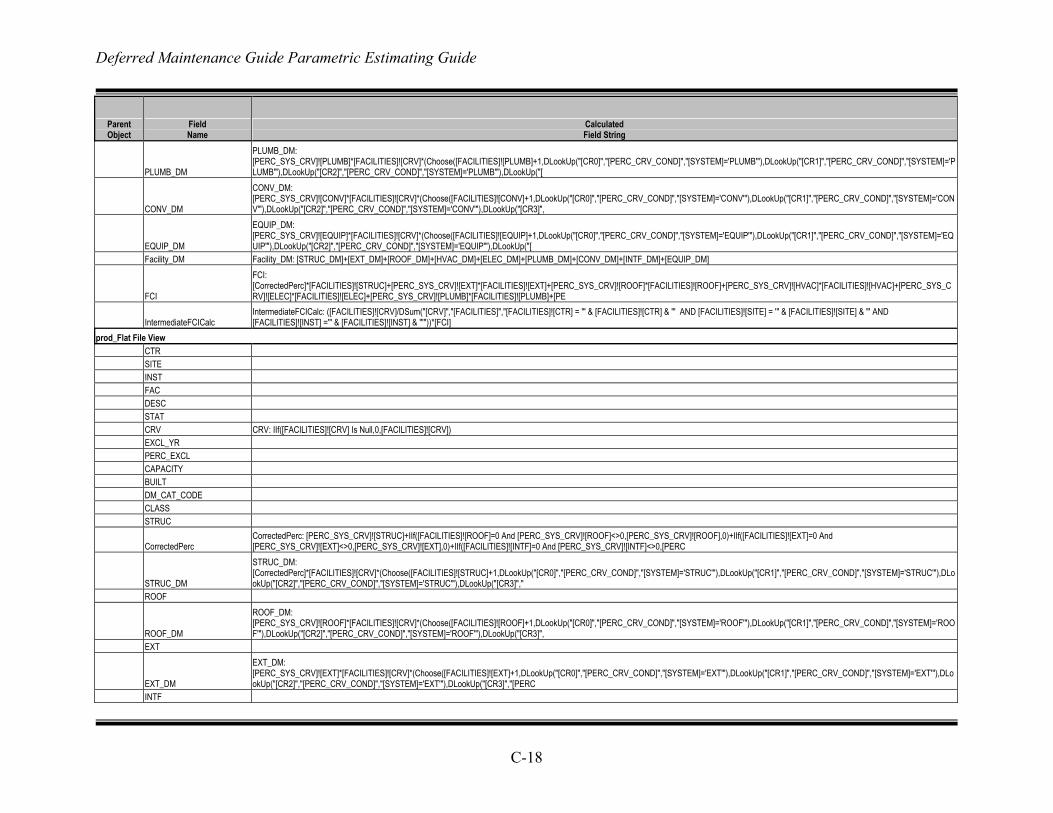
Deferred Maintenance Guide Parametric Estimating Guide
C-18
Parent Object
Field Name
Calculated Field String
PLUMB_DM
PLUMB_DM: [PERC_SYS_CRV]![PLUMB]*[FACILITIES]![CRV]*(Choose([FACILITIES]![PLUMB]+1,DLookUp("[CR0]","[PERC_CRV_COND]","[SYSTEM]='PLUMB'"),DLookUp("[CR1]","[PERC_CRV_COND]","[SYSTEM]='PLUMB'"),DLookUp("[CR2]","[PERC_CRV_COND]","[SYSTEM]='PLUMB'"),DLookUp("[
CONV_DM
CONV_DM: [PERC_SYS_CRV]![CONV]*[FACILITIES]![CRV]*(Choose([FACILITIES]![CONV]+1,DLookUp("[CR0]","[PERC_CRV_COND]","[SYSTEM]='CONV'"),DLookUp("[CR1]","[PERC_CRV_COND]","[SYSTEM]='CONV'"),DLookUp("[CR2]","[PERC_CRV_COND]","[SYSTEM]='CONV'"),DLookUp("[CR3]",
EQUIP_DM
EQUIP_DM: [PERC_SYS_CRV]![EQUIP]*[FACILITIES]![CRV]*(Choose([FACILITIES]![EQUIP]+1,DLookUp("[CR0]","[PERC_CRV_COND]","[SYSTEM]='EQUIP'"),DLookUp("[CR1]","[PERC_CRV_COND]","[SYSTEM]='EQUIP'"),DLookUp("[CR2]","[PERC_CRV_COND]","[SYSTEM]='EQUIP'"),DLookUp("[
Facility_DM Facility_DM: [STRUC_DM]+[EXT_DM]+[ROOF_DM]+[HVAC_DM]+[ELEC_DM]+[PLUMB_DM]+[CONV_DM]+[INTF_DM]+[EQUIP_DM]
FCI
FCI: [CorrectedPerc]*[FACILITIES]![STRUC]+[PERC_SYS_CRV]![EXT]*[FACILITIES]![EXT]+[PERC_SYS_CRV]![ROOF]*[FACILITIES]![ROOF]+[PERC_SYS_CRV]![HVAC]*[FACILITIES]![HVAC]+[PERC_SYS_CRV]![ELEC]*[FACILITIES]![ELEC]+[PERC_SYS_CRV]![PLUMB]*[FACILITIES]![PLUMB]+[PE
IntermediateFCICalc IntermediateFCICalc: ([FACILITIES]![CRV]/DSum("[CRV]","[FACILITIES]","[FACILITIES]![CTR] = '" & [FACILITIES]![CTR] & "' AND [FACILITIES]![SITE] = '" & [FACILITIES]![SITE] & "' AND [FACILITIES]![INST] ='" & [FACILITIES]![INST] & "'"))*[FCI]
prod_Flat File View CTR SITE INST FAC DESC STAT CRV CRV: IIf([FACILITIES]![CRV] Is Null,0,[FACILITIES]![CRV]) EXCL_YR PERC_EXCL CAPACITY BUILT DM_CAT_CODE CLASS STRUC
CorrectedPerc CorrectedPerc: [PERC_SYS_CRV]![STRUC]+IIf([FACILITIES]![ROOF]=0 And [PERC_SYS_CRV]![ROOF]<>0,[PERC_SYS_CRV]![ROOF],0)+IIf([FACILITIES]![EXT]=0 And [PERC_SYS_CRV]![EXT]<>0,[PERC_SYS_CRV]![EXT],0)+IIf([FACILITIES]![INTF]=0 And [PERC_SYS_CRV]![INTF]<>0,[PERC
STRUC_DM
STRUC_DM: [CorrectedPerc]*[FACILITIES]![CRV]*(Choose([FACILITIES]![STRUC]+1,DLookUp("[CR0]","[PERC_CRV_COND]","[SYSTEM]='STRUC'"),DLookUp("[CR1]","[PERC_CRV_COND]","[SYSTEM]='STRUC'"),DLookUp("[CR2]","[PERC_CRV_COND]","[SYSTEM]='STRUC'"),DLookUp("[CR3]","
ROOF
ROOF_DM
ROOF_DM: [PERC_SYS_CRV]![ROOF]*[FACILITIES]![CRV]*(Choose([FACILITIES]![ROOF]+1,DLookUp("[CR0]","[PERC_CRV_COND]","[SYSTEM]='ROOF'"),DLookUp("[CR1]","[PERC_CRV_COND]","[SYSTEM]='ROOF'"),DLookUp("[CR2]","[PERC_CRV_COND]","[SYSTEM]='ROOF'"),DLookUp("[CR3]",
EXT
EXT_DM
EXT_DM: [PERC_SYS_CRV]![EXT]*[FACILITIES]![CRV]*(Choose([FACILITIES]![EXT]+1,DLookUp("[CR0]","[PERC_CRV_COND]","[SYSTEM]='EXT'"),DLookUp("[CR1]","[PERC_CRV_COND]","[SYSTEM]='EXT'"),DLookUp("[CR2]","[PERC_CRV_COND]","[SYSTEM]='EXT'"),DLookUp("[CR3]","[PERC
INTF
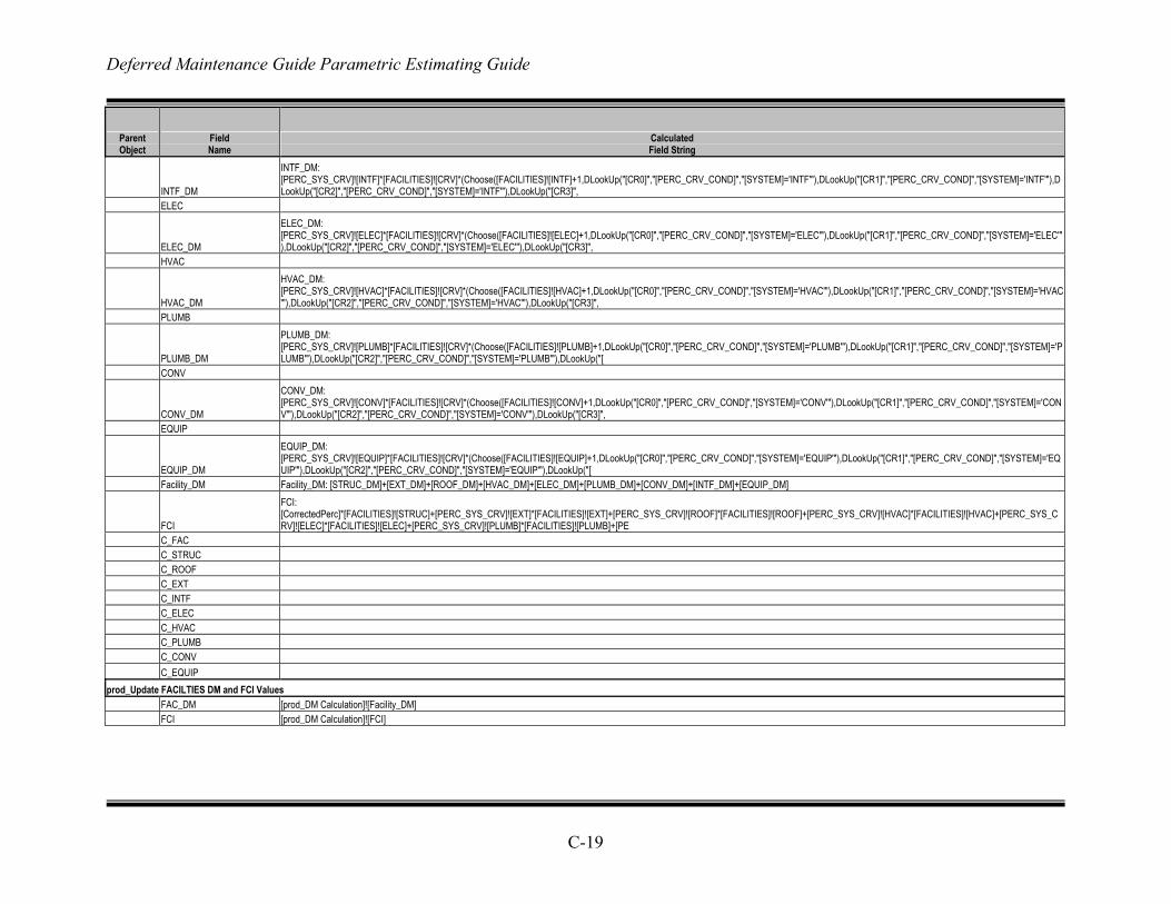
Deferred Maintenance Guide Parametric Estimating Guide
C-19
Parent Object
Field Name
Calculated Field String
INTF_DM
INTF_DM: [PERC_SYS_CRV]![INTF]*[FACILITIES]![CRV]*(Choose([FACILITIES]![INTF]+1,DLookUp("[CR0]","[PERC_CRV_COND]","[SYSTEM]='INTF'"),DLookUp("[CR1]","[PERC_CRV_COND]","[SYSTEM]='INTF'"),DLookUp("[CR2]","[PERC_CRV_COND]","[SYSTEM]='INTF'"),DLookUp("[CR3]",
ELEC
ELEC_DM
ELEC_DM: [PERC_SYS_CRV]![ELEC]*[FACILITIES]![CRV]*(Choose([FACILITIES]![ELEC]+1,DLookUp("[CR0]","[PERC_CRV_COND]","[SYSTEM]='ELEC'"),DLookUp("[CR1]","[PERC_CRV_COND]","[SYSTEM]='ELEC'"),DLookUp("[CR2]","[PERC_CRV_COND]","[SYSTEM]='ELEC'"),DLookUp("[CR3]",
HVAC
HVAC_DM
HVAC_DM: [PERC_SYS_CRV]![HVAC]*[FACILITIES]![CRV]*(Choose([FACILITIES]![HVAC]+1,DLookUp("[CR0]","[PERC_CRV_COND]","[SYSTEM]='HVAC'"),DLookUp("[CR1]","[PERC_CRV_COND]","[SYSTEM]='HVAC'"),DLookUp("[CR2]","[PERC_CRV_COND]","[SYSTEM]='HVAC'"),DLookUp("[CR3]",
PLUMB
PLUMB_DM
PLUMB_DM: [PERC_SYS_CRV]![PLUMB]*[FACILITIES]![CRV]*(Choose([FACILITIES]![PLUMB]+1,DLookUp("[CR0]","[PERC_CRV_COND]","[SYSTEM]='PLUMB'"),DLookUp("[CR1]","[PERC_CRV_COND]","[SYSTEM]='PLUMB'"),DLookUp("[CR2]","[PERC_CRV_COND]","[SYSTEM]='PLUMB'"),DLookUp("[
CONV
CONV_DM
CONV_DM: [PERC_SYS_CRV]![CONV]*[FACILITIES]![CRV]*(Choose([FACILITIES]![CONV]+1,DLookUp("[CR0]","[PERC_CRV_COND]","[SYSTEM]='CONV'"),DLookUp("[CR1]","[PERC_CRV_COND]","[SYSTEM]='CONV'"),DLookUp("[CR2]","[PERC_CRV_COND]","[SYSTEM]='CONV'"),DLookUp("[CR3]",
EQUIP
EQUIP_DM
EQUIP_DM: [PERC_SYS_CRV]![EQUIP]*[FACILITIES]![CRV]*(Choose([FACILITIES]![EQUIP]+1,DLookUp("[CR0]","[PERC_CRV_COND]","[SYSTEM]='EQUIP'"),DLookUp("[CR1]","[PERC_CRV_COND]","[SYSTEM]='EQUIP'"),DLookUp("[CR2]","[PERC_CRV_COND]","[SYSTEM]='EQUIP'"),DLookUp("[
Facility_DM Facility_DM: [STRUC_DM]+[EXT_DM]+[ROOF_DM]+[HVAC_DM]+[ELEC_DM]+[PLUMB_DM]+[CONV_DM]+[INTF_DM]+[EQUIP_DM]
FCI
FCI: [CorrectedPerc]*[FACILITIES]![STRUC]+[PERC_SYS_CRV]![EXT]*[FACILITIES]![EXT]+[PERC_SYS_CRV]![ROOF]*[FACILITIES]![ROOF]+[PERC_SYS_CRV]![HVAC]*[FACILITIES]![HVAC]+[PERC_SYS_CRV]![ELEC]*[FACILITIES]![ELEC]+[PERC_SYS_CRV]![PLUMB]*[FACILITIES]![PLUMB]+[PE
C_FAC C_STRUC C_ROOF C_EXT C_INTF C_ELEC C_HVAC C_PLUMB C_CONV C_EQUIP prod_Update FACILTIES DM and FCI Values FAC_DM [prod_DM Calculation]![Facility_DM] FCI [prod_DM Calculation]![FCI]
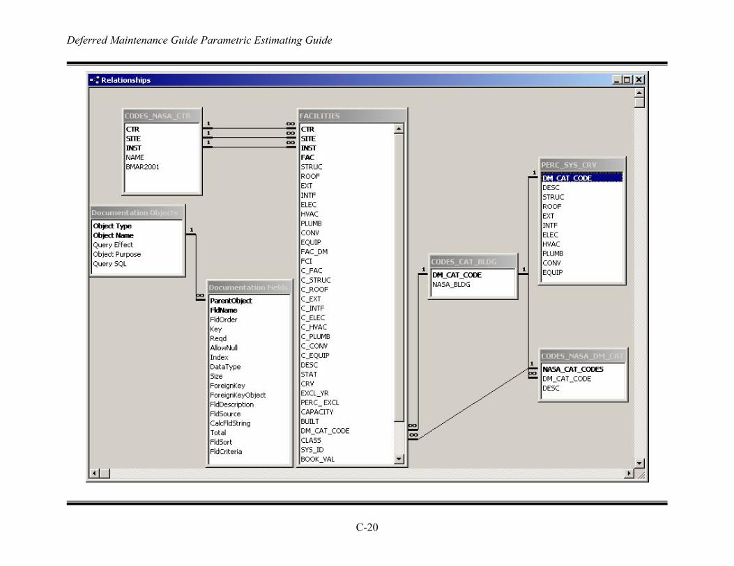
Deferred Maintenance Guide Parametric Estimating Guide
C-20


