SHIP PRODUCTION COMMITTEE FACILITIES AND ENVIRONMENTAL EFFECTS SURFACE PREPARATION AND COATINGS DESIGN/PRODUCTION INTEGRATION HUMAN RESOURCE INNOVATION MARINE INDUSTRY STANDARDS WELDING INDUSTRIAL ENGINEERING EDUCATION AND TRAINING THE NATIONAL SHIPBUILDING RESEARCH PROGRAM October 1996 NSRP 0476 Evaluation of Shipbuilding CAD/CAM Systems (Phase I) U.S. DEPARTMENT OF THE NAVY CARDEROCK DIVISION, NAVAL SURFACE WARFARE CENTER in cooperation with National Steel and Shipbuilding Company San Diego, California
Transcript
SHIP PRODUCTION COMMITTEEFACILITIES AND ENVIRONMENTAL EFFECTSSURFACE PREPARATION AND COATINGSDESIGN/PRODUCTION INTEGRATIONHUMAN RESOURCE INNOVATIONMARINE INDUSTRY STANDARDSWELDINGINDUSTRIAL ENGINEERINGEDUCATION AND TRAINING
THE NATIONALSHIPBUILDINGRESEARCHPROGRAM
October 1996NSRP 0476
Evaluation of Shipbuilding CAD/CAMSystems (Phase I)
U.S. DEPARTMENT OF THE NAVYCARDEROCK DIVISION,NAVAL SURFACE WARFARE CENTER
in cooperation with
National Steel and Shipbuilding CompanySan Diego, California
Report Documentation Page Form ApprovedOMB No. 0704-0188
Public reporting burden for the collection of information is estimated to average 1 hour per response, including the time for reviewing instructions, searching existing data sources, gathering andmaintaining the data needed, and completing and reviewing the collection of information. Send comments regarding this burden estimate or any other aspect of this collection of information,including suggestions for reducing this burden, to Washington Headquarters Services, Directorate for Information Operations and Reports, 1215 Jefferson Davis Highway, Suite 1204, ArlingtonVA 22202-4302. Respondents should be aware that notwithstanding any other provision of law, no person shall be subject to a penalty for failing to comply with a collection of information if itdoes not display a currently valid OMB control number.
1. REPORT DATE OCT 1996
2. REPORT TYPE N/A
3. DATES COVERED -
4. TITLE AND SUBTITLE The National Shipbuilding Research Program, Evaluation ofShipbuilding CAD/CAM Systems (Phase I)
5a. CONTRACT NUMBER
5b. GRANT NUMBER
5c. PROGRAM ELEMENT NUMBER
6. AUTHOR(S) 5d. PROJECT NUMBER
5e. TASK NUMBER
5f. WORK UNIT NUMBER
7. PERFORMING ORGANIZATION NAME(S) AND ADDRESS(ES) Naval Surface Warfare Center CD Code 2230-Design Integration TowerBldg 192, Room 128 9500 MacArthur Blvd Bethesda, MD 20817-5700
8. PERFORMING ORGANIZATIONREPORT NUMBER
9. SPONSORING/MONITORING AGENCY NAME(S) AND ADDRESS(ES) 10. SPONSOR/MONITOR’S ACRONYM(S)
11. SPONSOR/MONITOR’S REPORT NUMBER(S)
12. DISTRIBUTION/AVAILABILITY STATEMENT Approved for public release, distribution unlimited
13. SUPPLEMENTARY NOTES
14. ABSTRACT
15. SUBJECT TERMS
16. SECURITY CLASSIFICATION OF: 17. LIMITATION OF ABSTRACT
SAR
18. NUMBEROF PAGES
206
19a. NAME OFRESPONSIBLE PERSON
a. REPORT unclassified
b. ABSTRACT unclassified
c. THIS PAGE unclassified
Standard Form 298 (Rev. 8-98) Prescribed by ANSI Std Z39-18
DISCLAIMER
These reports were prepared as an account of government-sponsored work. Neither theUnited States, nor the United States Navy, nor any person acting on behalf of the UnitedStates Navy (A) makes any warranty or representation, expressed or implied, with respectto the accuracy, completeness or usefulness of the information contained in this report/manual, or that the use of any information, apparatus, method, or process disclosed in thisreport may not infringe privately owned rights; or (B) assumes any liabilities with respect tothe use of or for damages resulting from the use of any information, apparatus, method, orprocess disclosed in the report. As used in the above, “Persons acting on behalf of theUnited States Navy” includes any employee, contractor, or subcontractor to the contractorof the United States Navy to the extent that such employee, contractor, or subcontractor tothe contractor prepares, handles, or distributes, or provides access to any informationpursuant to his employment or contract or subcontract to the contractor with the UnitedStates Navy. ANY POSSIBLE IMPLIED WARRANTIES OF MERCHANTABILITY AND/ORFITNESS FOR PURPOSE ARE SPECIFICALLY DISCLAIMED.
NSRP 0476
Final Report
EVALUATION OF SHIPBUILDINGCAD/CAM SYSTEMS
(PHASE I)
Submitted to:U.S. Navy
by:National Steel & Shipbuilding Co.
San Diego, CA 92186Project Director:
John Horvath
Principal Investigator:Richard C. Moore
October 1996
ACKNOWLEDGMENTS
The authors gratefully acknowledge the assistance provided by the following companies,which made this study possible:
Black and VeatchCaretronic Ingenieurburo GmbH
Hitachi Ariake WorksHowaldtswerke-Deutsche Werft AG
Industrial Technology InstituteIshikawajima-Harima Heavy Industries
IntergraphKockums Computer Systems
Logimatic Marine Consultants ANMitsubishi Heavy Industries
Norddeutsche Itiormations Systems GmbHOdense Steel Shipyard
Sener Ingenieria y SistemasSMK Ingenieurburo
Verolrne Scheepswerf Heusden b.v.
The special support and encouragement of Torben Anderson at Odense SteelShipyard was especially appreciated. Without his able assistance in organizing theevaluation visits, and his participation in the Ship Production SymposiumCAD/CAM/CIM Workshop, this evaluation could not have been accomplished.
Similarly, the assistance of Axel Schroeter at SMK Ingenieurburo is especiallyacknowledged. He was instrumental in organizing the evaluation of shipyards utilizingcommercial shipbuilding software systems and their supporting consultants and suppliers.
A list of participants on the shipbuilding CAD/CAM/CIM evaluation project teamis included in Appendix H. Likewise, the participants from the above organizations are alsolisted. The preparation and open discussion by these participants was instrumental tothese evaluations.
1.0 EXECUTIVE SUMMARY
Commercial shipbuilding orders have been increasing worldwide and, for certainproduct segments, are expected to experience continued strength, possibly for severaldecades. This follows a 10+ year period during which weak demand could not sustain theavailable capacity resulting in subsidized prices, voluntary production limits, and numerousshipyard consolidations and closings. With an eye to the more recent market expansion,new capacity is now being added, most notably in regions previously not participating inany significant shipbuilding. These regions tend to enjoy labor cost currency exchange rate,and modem facility advantages over the world’s traditional shipbuilders in Europe andJapan.
The world’s traditional leading commercial shipbuilders have not been idle. Inefforts to compete profitably in today’s shipbuilding markets characterized by over-capacity and extreme price pressures, these yards have developed various strategies toreduce shipbuilding costs and schedules significantly. The strategies include aggressivebusiness practices, new or significantly enhanced computer technologies, factoryautomation, capital investments, and an unfaltering attention to process discipline andcontinuous process improvement. Computer-Aided Design (CAD) technology has beenevolving in these shipyards since the 1970s. In the late 1980s and early 1990s thistechnology has been significantly enhanced through the addition of Computer-AidedManufacturing (CAM) and factory automation, especially in cutting and welding. The1990s is seeing the integration of these engineering and production technologies withplanning and business systems. Truly Computer-Integrated Manufacturing (CIM) isemerging as one of the technologies of the 1990s by which world-class commercialshipbuilders plan to maintain or return to profitable competition in world markets.
This project’s Phase 1 Assessments of shipyards and software developers providesboth overview and depth into “world class” commercial shipbuilding operations. Shipyardsin both Europe and Japan, which combined profitable operation and extensive use ofcomputer technology in their operations, were initially studied. Later, specific assessmentswere conducted regarding use of commercially available CAD/CAM shipbuilding softwarein smaller or “2nd tier” shipyards.
All of the shipyards studied have some of the highest average labor rates and thelowest labor content per CGT (compensated gross ton). These yards were selected in orderto provide the best information concerning possible direction for U.S. shipbuildersapproach to new CAD/CAM/CIM systems to achieve even better results than thosestudied. Our assessments indicate that this performance is a result of aggressive businesspractices that:
Ž provide on-going market share and business backlog;l continue profitable operation in spite of relentless price and schedule competition;
Ž use the best practices available related to people, processes, facilities andtechnology.
This report concentrates on the specifics of technology, but it is not possible to de-couple technology from the other factors listed above. Specifically, we have observed thatcertain technologies - in particular CAD/CAM/CIM and accuracy control - are essentialenabling ingredients in 1996 “world class” commercial shipbuilding. However, effectiveCAD/CAM/CIM and accuracy (i.e. elimination of variations) technologies are not the onlydeciding factors.
The assessed shipyards represent the survivors of significant industry reductions inboth Japan and Europe. These shipyards have adopted strategies that produced improvedbusiness results primarily through continually reducing materials costs and labor content.Lower cost alternatives have also been developed, such as reliance on managed networks ofsuppliers and subcontractors for many components and services. Actual on-site shipyardwork concentrates on only those tasks that the yard does best their “core competencies.”For example, in all shipyards, structural fabrication was a core competency.
A key factor in achieving essential business improvements appeared to be a clearidentification and communication of the business goal and strategy to the work force.This process is “top-down:’ driven with executive management actively supporting theinitiatives with intensity over the full duration required for implementation. Just asimportantly, the work force is directly involved in understanding the barriers and designingand implementing the process changes from the bottom up. The processes were observedto be handled in different ways in the different cultures. At Hitachi, each employeeprovides one or two suggestions per month that are all reviewed by management and over50 percent are implemented. At Odense, all executives, production management, and unionworkers are involved with the approval of estimates and schedules for a new ship contract.During project execution, all are accountable for achieving the required contractperformance.
The yards studied are in the range of 20-30 labor hours per CGT, with Odensequoting ten labor hours per ton of steel for structural work. Due to different strategies andcore competencies, these figures are difficult to correlate with the specific work forceinformation provided. However, the small number of total workers is consistent with thequoted productivity.
The following report is assembled as a descriptive overview of the informationgleaned by the project team. Detail is omitted by necessity rather than choice. However,the detail has been considered by the team during Phase 2 of the project in developing therequirements for a world-class, future-oriented U.S. shipbuilding CAD/CAM/CIM system.Access to detailed information collected during the assessment visits is available through theindividual team members.
2.0 BACKGROUND AND INTRODUCTION
2.1 BACKGROUND
This report is the Phase I final report of the National Shipbuilding ResearchProgram (NSRP) project (Project Number 4-94-1) to evaluate world-class shipbuilders’existing CAD/CAM/CIM system implementations. Five U.S. shipyards participated inthis study along with personnel from University of Michigan, Proteus Engineering, andCybo Robots. Project participants have backgrounds in design, computer-aided design(CAD), manufacturing processes, computer-aided manufacturing (CAM), productionplanning, and computer-integrated manufacturing/management (CIM). The results of thisevaluation provided the basis for the CAD/CAM/CIM Workshop presented inconjunction with the 1996 Ship Production Symposium, and will be used as backgroundin Phase II of the project to develop requirements for future shipbuildingCAD/CAM/CIM systems.
Due in part to a heavy shipbuilding workload by the world-class Europeanshipyards, only the Odense Steel Shipyard could undertake the evaluation in the depthdesired by the project team. This shipyard utilizes systems built around the HICADECproduct modeling software developed by Hitachi Zosen. Consequently, the project planwas revised to include reviews of two other world-class shipbuilding software systemsduring the European shipyard visit trip: TRIBON from Kockums Computer Systemsand FORAN from Senermar. These reviews were helpful in better understandingdifferences in software systems and the effects these differences have in implementationstrategies. These reviews will also be used in the second phase of the project, which callsfor the development of requirements for future-oriented systems that can materiallyimprove U.S. shipyard productivity and, as a result, competitiveness.
A contributing factor to the cooperation and openness exhibited by Odense inhosting the NSRP evaluation team is believed to be the value Odense places on NSRPresearch and reports. Torben Andersen, Exec. V-P and our principal host, stated thatOdense has benefited over the years from this type of research and open reporting.
The “European Practice” descriptions in this report are primarily based on OdenseSteel Shipyard practices. The tools used at Odense appear to be a “patchwork quilt” oftools and systems that have evolved at Odense over the last ten to twelve years. Some ofthe tools are “3rd party” software products while the majority are “home grown”applications designed to either integrate or interface with existing tools and/or databases.Clearly the CAD/CAM/CIM approaches taken in hull structure and outfitting are notidentical. Noticeably missing from the overall Odense capability were effective cross-discipline associativity and topological product modeling. Noticeably abundant was thedeployment of systems throughout the many functional areas of the shipyard and the
1
high degree of integration between CAD product models and other functional systems(e.g. purchasing, production planning) and automated robotic welding facilities.
The “Japanese Practice” descriptions in this report are based primarily on visitsto Hitachi and Mitsubishi shipyards. These two visits provided details that confirmedmany of the approaches initially observed at Odense. Both Japanese shipyards havedeveloped their CAD/CAM/CIM approaches internally and have also implemented theirown applications to reflect internal processes and practices. Both yards are now part of anational effort to utilize CAD/CAM/CIM as a major improvement tool in increasingshipbuilding productivity and reducing product cycle times.
Hitachi and Mitsubishi differ in their approach to product development, withMitsubshi concentrating on small lots or even single ship product development whileHitachi focuses on medium lot size to long run product development. Both yards havesignificant facilities in which utilization is regulated as a national approach to stable shipprices. In this environment, the facilities have been downsized in total output byreducing the work force and the number of shifts worked. It appears that both yards havein the past, and could again, double or triple their output if market conditions allowed.The production processes and work force reflect constant improvement over thirty yearsand are considered the best available for assessment. Factory automation of steel cuttingand assembly welding is very advanced and important in all shipyards’ current and futureplans.
2.2 REPORT ORGANIZATION
Following the Executive Summary, this report is comprised of six main subjectareas as follows:
l Background and Introduction (Section 2.0)l Significant Findings (Section 3.0)Ž Shipyard Visit Reports (Sections 4.0 through 9.0)l Commercial CAD/CAM System Visit Reports (Sections 10.0 through 13.0)Ž Other Visit Reports (Sections 14.0 and 15.0)
Additional information, acquired or developed during the course of this project,has been included in appendices to this report. In addition to providing some of thedetails about the project methodology and specific survey responses, these appendicesprovide additional background material about shipyard practices that often relate to theindividual shipyard implementations of CAD/CAM/CIM technology.
3.0 SIGNIFICANT FINDINGS
3.1 SHIPBUILDING BUSINESS OBJECTIVES
The shipyards and other businesses assessed were selected in order to provide thebest Mormation concerning possible direction for U.S. shipbuilders’ approach to newCAD/CAM/CIM systems to achieve even better results than those studied. Ourassessments indicate that this performance is a result of aggressive business practicesthat:
Ž provide on-going market share and business backlog;l continue profitable operation in spite of relentless price and schedule competition;l use the best practices available related to people, processes, facilities, and
technology.
This report concentrates on specifics of technology. Specifically, we haveobserved that technology - in particular CAD/CAM/CIM technology - is an essentialenabling ingredient in 1996 “world class” commercial shipbuilding. However, effectiveCAD/CAM/CIM technology is not the deciding factor.
To futher understand this point, we have selected examples of the businesspractices that are considered significant in achieving and sustaining a competitivecommercial shipbuilding or industrial capability. These examples will be further expandedin the Phase 2 requirements report. Examples of business practices include:
New product developmentCustomization of current productsReduced customer/supplier/subcontractor riskSufficient workload for fulll & consistent use of core resourcesReduced cost and contract cycleReduced cost througlxŽ Core competencies (project design/pkuming/procurement/execution; hull assembly
& erection; pipe fabrication hull & tank coatings; outfitting machinery modules)Ž Variance elimination (product & schedule/activities)Ž HumanwareŽ Quality assurance by/at worker levelsŽ Design standards and process standardsl Minimal-to-no customer involvement in internal processes (either business or
production)Reduced contract cycle through:Ž Elimination of design, procurement, and production engineering errors/omissions
3
Ž Early project schedule simulationŽ Effective proble/crisis resolution
Many of the practices relate to processes that are essential to shipbuilding andhave been improved incrementally over long periods. Others are more revolutionary andare based on continually questioning the business opportunities with customers andsuppliers given changes in underlying constraints. The most effective practices appear tobe based on very subtle differences in core corporate understanding and attitudes towardthe business environment. This business environment is a complete system incIudingemployees, customers, suppliers, facilities, products, processes, and communications.CAD/CAM/CIM technology implementation was observed to provide a critical tool toleverage subtle differences in approach to commanding differences in performance. Otherapproaches rely on differences in the way people use CAD/CAM/CIM technologies toimprove performance and productivity. This can be referred to as “humanware” or theinvolvement of people in the use of technologies. “Humanware” practices provide thesustaining core of knowledge and capability to which automation can bring intenseleverage for improvement. Effective automation without “humanware” was not observedin any of the companies assessed.
3.2 TECHNOLOGY ALIGNMENT
A major finding relates to the reasons behind use of technology. As previouslystated, the companies assessed had adopted aggressive business practices. Further, theuse of technology was not pursued for its own sake, but as an enabler to achieve thebusiness objective. Business objectives of the assessed companies had been effectivelytransformed into implementation plans and projects leading to new or modified processes.People in the organizations brought about both the vision for the improved businesspractice and the implementation approach.
As with many new approaches or improved processes, certain portions werecopied from previous successful implementors in a related approach requiring constantbenchmarking of competitor’s processes. However, many of the examples above requiredsignificant basic research and development before feasibility could be determined as nodirect implementation of the approach was available. It appears that carefulunderstanding of the needed, desired, or possible business improvement is a fundamentalpart of technology considerations.
The cost, time, and resource commitment for technology could not come withoutmanagement understanding and involvement in the envisioning and planning processes.Feasibility and eventual full implementation is integrated with national or communityfunded and shared efforts, such as the European Community R&D robot projects or theJapanese Ship & Ocean Foundation funded CIM development. Also, intimate process
4
knowledge is needed of the existing processes to understand the barriers to businessobjectives and the potential paths around the barriers. The real secret is to determine thebottlenecks in the processes or barriers in business practice that control or limit profit.That understanding can equip management to lead or direct changes in the most effectivecourse.
Phase 1 will develop a tighter link between specific business cases and theCAD/CAM/CIM technical requirements. The clear message from the assessed companiesis that investment in technology is appropriate if it has a clear path to improved businessresults that create added profits. Other activities, which do not meet this test, areeventually dropped. The challenge is to do the envisioning and analysis of what is mostprobable to reach the result, and not to simply pursue the newest technology withoutconsidering the potential return.
3.3 IMPLEMENTATION STRATEGIES
We have sought to document the observed strategies as Significant Findings and toidentify the factors that seem most important to their success. The shipbuildingexamples are divided into several areas of activity. These include:
Ž independent benchmarking and product/process analysisl independent process implementationl cooperative research & developmentŽ partnering implementation
The strategies, which seem the most relevant to current U.S. shipbuildingrequirements, combine both the business objectives analysis approach and theimplementation activities above. These include:
Ž concentration on “core competencies;” i.e. Doing what you do best and findingpartners, who are also “best,” to do the rest. Example - Odense corecompetencies in Design/Production/Project coordination, structural work throughship completion, steel pipe fabrication, assembly of major outfit t modules, andunit-level application of coatings.
Ž elimination of variations in performance leading to improved through-put andaccompanying improvement in productivity. Most significant examples include:l structural part and assembly dimensionsŽ duration of planned work operationsl supplier and subcontractor delivery and qualityŽ workers responsible for quality and schedule withminimum support and no
inspection
Ž use of Product Model data and highly integrated applications to:Ž eliminate errors and omissions in design productsŽ reduce risk in early estimating and scheduling of labor, material, and facilitiesŽ provide effective information for factory automation using robotics at no
increase of touch labor or engineering schedule. Robots used in steelcutting/marking, welding, and painting
Ž increase product reliability and performance through sophisticated analysisŽ use of their people as the major part of systematic improvements to
performance and flexibility. Example - Japanese all speak of “humanware” inthe same manner as “software and hardware” in system development andimplementation.
ŽŽ Ž involvement in continuing research and development through partnershipswith both competitors and nonmarine industry groups. Examples: Japaneseshipyards in S & O Foundation CIM project, and Odense in EC projectsrelated to robot welding programming and control.
All assessed companies performed benchmarking and product/process analysis asroutine functions. These were effectively communicated although not through a formal orstandardized methodology. All companies were involved in both cooperative R&D effortsand partnering for implementation of products and processes. The partnering andcooperative efforts used varied and flexible groupings of needed experience. The relationsformed could be long term ( i.e. Odense and Hitachi in development of HICADEC ) or shortterm ( i.e. the 30-40 robot projects followed by Odense in developing its new controllerapproach). However, the most important observation is that the companies were responsiblefor implementation and applied the technology to targeted processes. This allows the subtledifferences of facilities and humanware to be considered and to form the sustaking knowledgeand ownership of the process needed to be successful. Eventual confirmation of atiaining thedesired business objective has to be measured and, if necessary, refined. Refinement brings inthe concept of continuous improvement and setting new business objectives ( i.e. Odenseimplementation of block welding robots led to the decision/need to reduce part dimensionalvariance).
To further illustrate this environment, Odense provided two stories, both involvingthe Chairman of AP Moeller Group ( the owner of Odense ), Mr. Moeller. In about 1980,Mr. Moeller was aware of the growing price delta in ships constructed in Asia versus Europe.He had a short meeting with the shipyard management and simply asked them to develop andimplement an approach in which he could continue to afford to build some of his ships atOdense. The result was a plan leading to current capabilities. Previous organizationalconflicts were put aside in the effort to achieve the larger and more important goal. Thesecond is on-going. Mr. Andersen, as Yard General Manager and new Partner in AP.Moeller, is frequently asked about the progress of process improvement projects, especiallythose using high technology solutions or cutting edge development. The pressure is alwaysto initiate additional projects.
6
3.4 CAPABILITIES AND OPERATIONS
Most shipyards looked remarkably similar. The copying effect with continuingbenchmarking and procurement of equipment from a small set of suppliers leads to thesimilarity of look. The differences are subtle as to why a particular yard has differentperformance. The primary reasons for different performance have been stated above.Specifics of each individual company is part of the specific company report.
In general, all shipbuilders were effective in steel production. The shipyards andBlack & Veatch (B&V) were also effective in design/production/procurement/projectcoordination. However, the most significant strength was in the leadership needed toassess the business objectives and translate those objectives into tactical plans fordevelopment and implementation of product and process changes. These changes keptthe leading companies ahead of their competitors.
3.5 APPLICATION COMMONALTIES
Software and hardware applications observed have commonalties as they relate tospecific processes. That is, where processes in the shipyards are identical, thenapplications have similar functions. The manner of interaction and the style of operationagain relate to the particular approach in place in the shipyard.
The three primary yards assessed and B&V all use home developed applicationsbuilt on external core technology. The investment in knowledge base explains the largestpart of the company’s success in use of CAD/CAM/CIM. The effort needed tounderstand how the applications relate to the process provides a very strong basis for useand improvement of the applications and the processes. The observations atHowaldtswerke-Deutsche Werft (HDW) (and NIS & SMK, as support integrators forHDW) indicate that use of third party applications, such as TRIBON, can be effectivewith appropriate support resources. KCS has stated that Japanese shipyards usingTRIBON have made large investment in understanding and using the system, evenincluding significant enhancements, prior to the decision to fully implement.
An example of differing philosophies affecting application styles is the Odensedevelopment of a planning and off-line programming application - PROMOS, and Hitachiperforming the same functions using PHI directly. Hitachi had decided that automationwas very important and needed to develop an “intelligent planning” application toimplement early stage detailed estimating. The applications at the base level wereHICADEC; the implementation was specific to the direction needed to implement thebusiness objectives.
3.6 UNIQUE IMPLEMENTATIONS
Unique implementations of CAD/CAM/CIM technology were found at Hitachi,Mitsubishi, and B&V. In each case the uniqueness of the application approach was areflection of the specific need of that business on the applications.
Hitachi had developed a support approach for basic design to improveinformation access in the tendering stage. This was combined with the intelligent planningapplication from the PHI database using 250 rules to plan the ship blocks and routing, aswell as the preliminary labor and task durations. Combined, these applications provideda significant preliminary design capability to ensure accurate cost and schedule predictionwith little time or labor needed.
Mitsubishi had developed a complete design and design analysis set ofapplications to support its direction to compete for one-off product development. TheDAVID and MATES applications were developed to provide for copying of designintent in structures to detail level from the hull lines and midship section. Analysis wasintegrated to assure initial consideration of powering, fatigue, loading, and operations,which were of particular interest to the owner and not normally considered until later inthe design process.
B&V had arranged its entire system around data-centric and computer-automatedapplication concepts. Taken together, these two concepts provided all data to allpotential participants in a project all of the time -24 hours a day world-wide, and theability to change/correct the project with minimal delay and disruption normallyassociated with CAD/CAM approached. The data are in the most abstract form commonto the process (i.e. similar to the desired form of NIDDESC/STEP AP descriptions), andprocesses are automated to work on the data using standards to produce the final outputof the process with minimum labor. As with other examples, B&V is directingdevelopment of these application approach based on business objectives.
4.0 ODENSE STEEL SHIPYARD
4.1 ODENSE SHIPYARD OVERVIEW
Odense Steel Shipyard Ltd. was founded in 1917 and consisted of a 40,000 DWTcapacity yard in Odense, Denmark. In 1957-1959, new facilities were constructed inMunkebo, just north of Odense. This yard was designed for 200,000 DWT maximumship size in two parallel construction halls and drydocks. The first vessels built at theMunkebo yard were 50,000 DWT product tankers for Chevron. In 1969, constructionbegan on a new building/crane/drydock complex for 1,000,000 DWT vessels. Steelfabrication capacity at the current shipyard is about 250,000 tons/year. Currentproduction is about 180,000 tons.
Current work underway at the yard during the NSRP team visit was transitioningfrom a six vessel 293,000 DWT VLCC to a nine vessel 4800 TEU container ship. AMaersk Line 1500 TEU container vessel (the TRSL ARCTURUS) arrived docksideduring the visit to begin a major overhaul of its slow-speed diesel main engine. TheVLCCS are priced at 750M Danish Krona (approximately $130M) and are currentlybeing produced in the 1,000,000 DWT facilities at a rate of three to four ships/year. Wewere told that the VLCCS are being produced at ten to twelve man-hours/ton. Accordingto Torben Anderson (Executive Vice President at Odense), the original 200,000 DWTfacilities are believed to be capable of somewhat less than 20 man-hours/ton.
The shipyard is part of the Odense-Lindo organization, which is part of the A.P.Moller Group. Odense-Lindo is primarily a container shipping company. Odense-Lindoincludes Maersk shipping and container manufacturing, Loksa Shipyard (Estonia), andRobitec as well as the Odense Steel Shipyard. Employment is about 4,000 in Odense-Lindo, of which 3,000 are at the Munkebo Shipyard (500 white collar). ThePlanning/EDP/ Automation department consists of about 40 people with about half ofthese people in the Robotics Automation/Projects/Sales group. In addition, about 22people from Maersk Data (another A.P. Moller Group organization) are resident atOdense supporting the information systems (hardware and software) used at the Odenseshipyard. Systems requirements and specifications are developed by the shipyard usersand the software development in done by Maersk Data personnel. A “help desk” systemis supported with an internally developed work/problem tracking system. An annualcontract is awarded to Maersk Data for these support services, which also includes sub-contracts to Data General for on-site (2 full-time employees) hardware maintenance on allcomputer hardware.
9
A newbuilding project is considered to have three phases; design, engineering, andconstruction. The design phase appears to be comparable to the concept, preliminary,and contract design phases typical of U.S. practice. The engineering phase appears to becomparable to the detailed design phase. Functional performance issues are addressed inboth the design and engineering phases with naval architecture issues being the primaryfocus in the design phase. Marine engineering issues (e.g. heat balances, pipe systempressures and flow, electrical system peformance, pipe thermal stress, etc.) are addressedin the engineering phase.
The current shipbuilding facilities consist of the two parallel 220,000 DWT vesselproduction lines built in 1957-1958 and the 1,100,000 DWT line built in 1969-1970.These facilities are very clean, well organized and laid out for efficient material handling.The facilities include 400 ton and 1,000 ton cranes. Most of the newbuilding work isdone in the 1,100,000 DWT facilities. The end portion of the large drydock nearest themain construction hall has been partitioned from the remainder of the drydock and iscurrently used for assembly of large midbody sections. Some offshore work has beendone recently in the 220,000 DWT line,s but they are generally used for storage and steelwork on blocks not suited for the more automated facilities. A sketch of the site facilitiesis included as Figure 4.1 and an aerial view is provided in Figure 4.2. The aerial viewshows a small portion of the 1,100,000 DWT drydock and 1,000 ton crane in theforeground. The original 220,000 DWT drydocks, cranes, berthing dock, and constructionhalls appear in the background.
The labor force is union organized, with a clear feeling that certain tasks areinappropriate for Danish labor. Despite considerable on-going work to complete the lastVLCC and the first 4800 TEU vessel, the yard appeared to have relatively fewproduction workers moving around compared with U.S. shipyards. The workforce didnot appear to be abundant, suggesting an extraordinary efficiency in the shipbuildingprocess.
Design areas (structure and outfitting) are open (no partitions), very clean, free ofclutter, and professional in appearance. Workstations are prevalent throughout theseareas. Most workstations have the extensive symbol tablets utilized in the CAD systemsof the early 1980s. For outfitting, these tablets were claimed to be more efficient than thepull-down menus provided by most modem CAD systems. The outfitting design officeprovides working space and CAD terminals for 10-12 engineers and 28 designers. Aboutone to two weeks of formal training and two to three months of on-the-job experience isrequired to train the designers.
The contract award schedule for newbuildings is 5 percent at contract award, 5percent at start of fabrication, 10 percent at launch, and 80 percent upon delivery. Thebreakdown of newbuilding costs was characterized as follows:
10
15-20% Direct Labor20% Overheads and other costs including energy, maintenance, EDP, etc.57-65% Materials and subcontractors
The design process is typically planned for a ten-month duration after whichproduction is started. The rough breakdown of design tasks during this period is asfollows:
Ž Contract awardŽ Phase I - Structure Definition and Design
Phase II - Production Definition and DesignDatabase separation (month 5)Order steel (months 7-8)
l Production start
Upper level management appears to have considerable involvement withoperational problems, and research and development efforts. Each morning theproduction area managers walk through their areas checking status and problems. Theythen meet with their VPS, who, in turn, meet with the President and Executive VPS toresolve any outstanding issues affecting operations. In this manner, senior management iskept abreast of all production status and problems.
4.2 BUSINESS STRATETEGY
The business strategy appears to have a long range focus, with emphasis on thelarge vessel product segmennt, in which Odense’s facilities and automation technologies candevelop and maintain steel fabrication competitiveness for current and future vesselcontracts. The large vessel segment includes double hull VLCCS (300,000 dwt class) andlarge container ships (4800+TEU class). Repair work is done for Maersk at the requestof the parent company. This kind of work, however, is not consistent with the “steel andpiping factory” business used for newbuildings and is not sought. The split between in-house work and vendors’ work seems to be driven by the “do what we do best”philosophy. Make versus buy decisions are continually being reviewed. With the
11
opening up of the low-labor-rate, Eastern European countries, new subcontractingopportunities are being explored to further Odense Shipyard’s competitiveness. Forexample, a yard in Estonia has been acquired that is currently being used to manufacturesmall hatch covers. Other uses of these facilities are being investigated.
The management strategy is focused on continuous improvement. The goal is tocontinue to improve processes, personnel, and facilities so they become increasingly moreefficient. Significant capital investments are made each year, justified by cost savingsover multiship building contracts. Since the end of 1994, Odense has added a 12-robotflat block welding assembly facility, a two-robot curved block assembly welding facility,and anew plasma cutting machine with inkjet marking. The yard is in the process ofbuilding anew blast and coating building.
Odense invests in personnel resources, as well. The best example is thedevelopment of people who are now pushing the envelope of robotic and other forms ofwelding automation. Likewise, the shipyard has developed personnel who continue todevelop and integrate a collection of CAD/CAM/CIM programs into effective systems.These systems include integrated product modeling and production managementfunctionality devised by Odense personnel supported by Maersk Data network andsoftware experts.
The typical award schedule is as follows; 5 percent at contract award, 5 percent atstart of fabrication, 10 percent at launch, and 80 percent at delivery for a total of about$150M per ship.
4.3 COMPETITIVE STRATEGIES
The shipbuilding strategies focus on lowest cost, shortest production timeapproaches. Material costs have been determined to be the number one driver forproductivity improvements. These costs have several elements; raw costs of materials,carrying costs (interest on funds tied up in materials), and “work in progress” (WIP)carrying costs on material and labor used to produce WIP inventory. Labor manhourswas not mentioned as a driver for productivity improvement developments. Severalelements of the Odense competitive strategies include:
Ž Facility rationalization
The Odense shipbuilding facilities are configured to produce large ships in aproduction line manner. The focus is on minimizing design time, minimizing constructiontime, and minimizing materials, and work-in-progress inventory. Internal analyses byOdense showed that when a six-month reduction in the time inventory is carried thisresulted in a savings in the millions of dollars range.
12
Ž Do what we do best (subcontract what others do best)
The Odense yard strengths appear to be steel and pipe fabrication, combined withheavy-lift (400 and 1,000 ton) cranes capable of handling large subassemblies andmodules. Most other work (e.g. electrical, joining, pipe surface prep and coatings,HVAC, etc.) is subcontracted. As described in Purchasing and Vendor Relationships(Section 4.9), a network of suppliers is cultivated and monitored for performance. Pre-package units from specialized vendors (e.g. complete head/shower units) are utilizedextensively to facilitate final outfitting. Most of the installation work, including joiningand HVAC, is completed by Odense. Notable exceptions are electrical/instrumentation(vendor installed) and final interior ballast and tank painting (work deemed unfit forDanish workers).
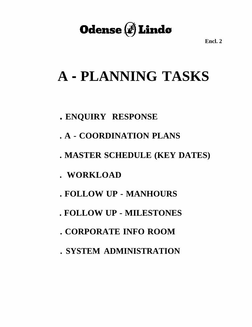
Ž High level of planning and control
The production planning is done in four levels with the managing directorauthorizing the overall “A-Planning; construction schedule” level. This entails only aboutfive key dates for each ship in the series and covers a 2-4 year timeframe. This planningaddresses overall shipyard resources including necessary skills and education, andallocation of contracts to subcontractors. “B-Planning” by production managementdetermines the modular breakdown, required resource schedules, and overall schedule ofactivity flow needed to achieve the construction schedule. This planning addresses a 6-12month time frame and constitutes the primary basis for monitoring construction status.The “C-Planning” addresses individual production area workloads over the upcoming12-week period. This planning is updated weekly. Within these periods, eachproduction department does “D-Planning” of the first 4 weeks’ work plans for efficientuse of resources in meeting the “C-Planning” production schedules. For example, pipebend tooling is scheduled based on meeting current and, to the extent practical, upcomingproduction needs for a specific pipe size, rather than changing after meeting only thecurrent needs for that pipe size. Rules-based programming is used to automate much ofthe estimating and job routing through shops.
Ž Justin time procurement and production (pull scheduling)
Within the parameters discussed above, materials and finished subassemblycomponents needed to support production schedules are procured (from vendors) andproduced (at the shipyard) according to the upcoming needs outlined in productionschedules. Arrangements with suppliers call for frequent materials restocking withminimal warehousing of stock on-site. Material requirements are prepared andcommunicated to each vendor by production planning to facilitate their restocking. Eachdepartment schedules its work based on needs to support the next eight to twelve weeksof production. Short term (four week) work plans in the various production areas aresimilarly scheduled.
13
Ž Automation and High tolerance manufacturing
Very stringent dimensional tolerances (e.g. within ±mm for profile cutouts) andsignificant emphasis on dimensional control was evident in every stage of fabrication.“Neat” construction (i.e. cut to size with no excess to be cut-to-fit later) is emphasizedalong with good fit-up at welded joints with a minimum of filler pieces. The good jointfit-up is essential to robotic welding, which, in turn, produces good weld quality with aminimum of rework. Likewise, use of collars is minimized by use of tight fitting cutoutsaround stiffener penetrations. Discipline and adherence to standards is also evidentthroughout the organization, which helps maximize efficiency through repetition. Mostautomation and standards seemed to emphasize simplicity for the operators andworkmen.
Odense’s future vision is to automate as much welding as possible. A key benefit is amajor reduction in training time; that is, the time to train a skilled welder versus the timerequired to train a computer operator to program the welding.
Ž Quality Assurance
Quality control functions were disbanded early in the Odense automation effort.The responsibility for quality is with the line organizations, including labor. Dimensionaldata are collected by the production workforce and used to make corrections as needed.Periodic audits are performed by a two person Quality Assurance Department. Theemphasis appears to be in fixing the process rather than in checking the output.
Ž Performance-based labor compensation
Under the wage agreement with the union labor, a bonus system is employed,which compensates labor for production as well as time spent on the job. Productionplanners set the rates or value for defined production tasks. While the exact method wasnot fully explained, it appears that 90 percent of labor’s agreed compensation is paidbased on hours worked. The remaining 10 percent is pooled and redistributed weekly ormonthly based on actual work group production versus these set rates or values. It waspointed out that some elements of the labor force more aggressively pursue these bonuspayments than others, with outfitters said to be earning up to $1 .00/hour more than theircounterparts in steel fabrication. It was clearly stated that a production task is completeonly when it meets correctness and accuracy standards. Any rework required tocomplete a task must be absorbed by production labor and affects their competing forbonus payments. This appears to be a key element in the quality assurance program.The system sounds quite complicated; claims can be made by labor for lost productiontime due to unavailability of needed materials or for equipment maintenance. Overall,however, the unionized labor force generates a sense of ownership for productivity at thegroup (i.e. work crew) level.
14
Ž Push production planning as far forward design process as practical
Figure 4.3 illustrates the Odense thinking in terms of production planning. Thedecisions made early in the design process (before construction begins) have the greatesteffect on total production costs. Consequently, the emphasis in much of the currentOdense development work is to push production considerations well forward into thedesign and engineering phases of a newbuilding project. This emphasis is evident in theuse of automation tools to help reconcile ship systems PIDs with the build strategy andcompile material and resource requirements very early in the design phase. It is alsoevident in the use of welding cost estimation algorithms during engineering (i.e. detailed)design. Furthering capabilities in this area seems to be a focus for Odense’s 5-yeardevelopment plan.
4.4 AUTOMATION
4.4.1 Background
Odense started to utilize NC data from the Steerbear system for plate cutting inthe mid-1960s. From 1971 through 1982, Odense utilized the Steerbear CAD software,which is now part of the TRIBON system from KCS. Concern over Kockums closing oftheir Malmo shipyard and difficulties with interfacing and getting software enhancementsimplemented in a timely fashion caused Odense to transition from Steerbear to an in-house system development in 1982. In 1983, a serious automation effort began withSupermini computers, CAD/CAM software, and automation of cutting and weldingintegrated with the CAD/CAM. This effort was concurrent with the introduction of“neat” construction methods with dimensional tolerances reduced from 2-3 mm to 1 mmfor double-hulled VLCC vessels. The original objective of the automation effort was toreduce material costs, primarily reducing inventory costs, as illustrated in Figure 4.4.
HICADEC was selected as the basic 3-D modeling system for the automationdevelopment and is still a key element of the Odense capabilities. While AUTOKONwas evaluated and deemed to be impressive, Odense was hesitant to source this softwarefi-om a software company without shipyard connections. In 1982, Odense bought theFORAN general design (Naval Architecture calculations) package, which was used untilabout two years ago when NAPA software was acquired. An agreement was made withHitachi Zosen in which Hitachi and Odense direct the HICADEC development effortsand Hitachi does the software development. Odense does considerable in-housedevelopment work on integration tools between HICADEC and other automationsystems (e.g. purchasing, material control, robotics, etc.) used at Odense.
15
Current hardware utilize UNIX in client-server arrangements. The entire shipyardsite is connected with a 100 MB/see fiber optic LAN ring providing redundantcommunication paths to minimize outage effects. Some 700-800 nodes are connected tothis LAN including 140 assorted UNIX workstations (actually a mixture of workstations,X-terminals, and PCs with X-Windows emulation). The UNIX server workstations(primarily Data General) are centrally located and provide 140 GBytes of mass storagecapacity. Electronic communications with Odense-Lindo headquarters in Copenhagen arelinked through this LAN. Future plans are to move to supercomputing with massivelyparallel processing to simulate manufacturing processes as well as design. The computerhardware chronology and fiture directions were described as follows:
1975- mainfrarne computing1985- super mini computers1995- client/server systems (UNIX)2005- massively parallel processors
4.4.2 Implementation Philosophy
Automation direction is top-down driven. The philosophy seems to be thatimprovement projects must be undertaken to ensure future business and that currentmargins must be divided between profits and ongoing process technology developmentsto ensure competitiveness for future business. The management horizon must be decades,not years. Torben Andersen described the automation of Odense as a direction that, oncebegun, has no turning back. It involves capital investment, which is continual andextensive. Once begun, it appears that these investments build upon themselves.
While the automation direction is top-down driven, the specific programs andimplementation design is mostly bottom-up. The importance of initiating processimprovement technology projects in response to line organization requests was stronglystressed. While this development process is perceived (by senior management) to beslower and less seamless, these problems are considered of secondary importancecompared to problems with selling R&D initiated projects to line organizations.
Automation and robotics projects are justified on series newbuildings projects; thenewest 12-head robotics block assembly welding station was said to cost $3.0M and isexpected to have a two to three ship payback period on the current nine vessel 4800 TEUcontainer ship order. This $3.OM cost is assumed to be the incremental equipment andfacility costs to adapt the robotics used for the previous VLCC robotics to the containervessel robotics facilities. Much of the development work underlying this and otherproduct model-based automated manufacturing processes was undoubtedly done on cost-shared European Community (EC) research programs (see Section 4.8).
16
4.4.3 Welding Robotics
The Odense Steel Shipyard has aggressively pursued robotic welding forenhancing production since 1987. It was suggested that optical camera sensors arepreferable to laser sensors because of their small size. Stereo imaging dimensional feed-back methods are being explored. The ROB-IN software developed by Odense is fullyimplemented and judged effective for flat plate assemblies. This approach is based onsimple line and arc descriptions of the weld line paths. The “AMROSE” technology,based on NURBS mathematical descriptions, is in initial (prototype) implementation forcurved plate assemblies and is still considered somewhat developmental. TechnomatixROBCAD and Deneb IGRIP software were evaluated for the curved plate programmingtask, but were considered to be too mathematically intensive for efficient off-lineprogramming. The assembly support fixturing in their curved panel welding cellincorporates a tilt axis to keep the welding position flat. “SMART WELDER”technology for outfitting (pipe sections) is still in the research stage, supported by severalEuropean Community (EC) joint research projects (see Section 4.8).
The primary benefits from the use of robotics technology were described asimproved weld quality and heightened attention to planning and quality issues. Tighttolerances are required for robotic welding, thus permeating strict attention to dimensionalcontrol throughout all fabrication processes. Welding productivity benefits werepresented as marginal, mostly related to planning work such that process tasks aresimpler and working conditions are better for individuals. The timely and accuratereporting of actual welding completed was suggested to be of more value than weldingproductivity enhancements. Similarly, the attention to dimensional accuracy at everystage of construction in support of effective robotic welding was described as one of themajor benefits. The discipline applied to achieving this accuracy made significant processimprovement occur in all operations, thus reducing costs and span times throughout theshipyard.
The accuracy approach to robotic welding explains Odense’s philosophyregarding sensor-based adaptive robotics. The U.S. is pursuing sensor-based adaptiveprocess control as a means to overcome a degree of assembly inaccuracy that it believescannot be avoided. The approach is to allow assemblies to have variances in position andfitup, utilizing adaptive control automation technology to sense and correct for thesevariations. This is in sharp contrast to the Odense position that production based onhighly accurate assemblies is inherently more effective in terms of costs and schedules.
The robotic welding technology and systems developed by Odense arecommercially available. Currently, installations other than at Odense are being used inNorway, France, Korea (2), and Denmark.
17
4.5 MAJOR CAD/CAM SYSTEMS
Odense began its automation effort in 1983 with the use of Steerbear. It later usedHICADEC and GRADE/G, a graphic system developed by Hitachi Zosen similar toIBM’s CATIA software. It appears that these systems provided 3-D product modelingtools and a somewhat open database architecture. Integration with manufacturing,planning, and management systems was not particularly well addressed by these CADtools. This section describes some of these and other key CAD/CAM tools that havebeen subsequently integrated into Odense systems. Section 4.6 describes similar planningand control systems, and Section 4.7 describes some of the integration methods and tools.
The central computer room is housed in a building adjacent to the design offices.This facility has five Data General UNIX servers. One of the servers is an IngressRDBMS server. It appears that Ingress is their database of choice for clientherverapplications. Ingress and HICADEC databases are stored on Data General CLAMONdisk arrays filled with 1.2 and 2.0 GB disk drives - a total capacity of 140 GigaBytes.The local area site network utilizes a 10MB/sec Ethernet and a variety of networkinghardware, specifically including Cabletron MAUs. The network is being upgraded with a100MI3 fiber FDDI.
4.5.1 Computer-Aided Engineering, Design and Manufacturing
GRADE/G is primarily a computer-aided drafting system, which has beeninterfaced with the HICADEC 3-D product modeling system. It is used for stand-alone2-D drawings. It also provides much of the capabilities to produce drawings based onextraction of the 3-D product model data. It was described as having been developed byHitachi Zosen about 10 years ago and being similar to the IBM CATIA system. It istablet menu driven.
HICADEC is the primary 3-D modeling system utilized at Odense. HICADEC-His used for hull structure modeling and HICADEC-P is used for outfitting. Thesoftware was developed and is maintained by Hitachi Zosen for Hitachi, Odense, and oneother shipyard. A brief description of this system is included in Section 13.0.
4.5.1.1 Hull Structure
The HICADEC-H system was demonstrated for building a tank top assemblyfrom scratch in an inner bottom unit. A batch program (BMTHIC, developed by BMTfor Odense) is used from a X-terminal to transfer the hull surface information fromHullSurf into HICADEC. An element drawing was produced by the designer for thisblock of structure. This drawing was really a view of the structural model similar to ascene in the AUTOKON module AUTODEF.
18
The first step in creating an element drawing involved setting boundary viewlimits (x,y,z) and a scale (for plotting purposes). A frame (X-Dist) table wasaccomplished during the BLINES conversion with BMTHIC. Planar surfaces are createdby specifying x-y, y-z, or x-z coordinates in a manner very similar to AUTOKON. Thetank top surface was created. The surface cut an intersection line with the shell.Transverse frames are automatically named with random numbers, which can then beoverridden with specific names. A large tablet was used as an input device almostexclusively for all demonstrations. The tablet overlay was filled with small cellscontaining macros and commands.
Odense uses a manual penetration list prepared by the outfit designer tocommunicate piping penetrations to the structural designer. As HICADEC-H andHICADEC-P are not integrated, the list is manually updated if an outfitt designer moves apipe and changes the shape and/or location of a penetration hole. Stiffener cutouts aredefined for the ship in a standard library. The library is copied from ship to ship andmodified as necessary. The cutouts are parametrically defined, that is, automaticallysized to the stiffener dimension and type.
The HICADEC-H modules appeared very similar to the AUTOKON AUTODEFmodule for defining structural parts. A point to be noted, however, is that graphically theuser is defining the 3-D structural model by working in 2-D views. The user can workinteractively in the standard plan, elevation, and section views. The database storesstructural data three dimensionally, but HICADEC does not have the visualizationsoftware to provide 3D graphics in the expected sense. There is a capability to producean isometric drawing with hidden line removal, but it is just a 2D drawing representation -it cannot be rotated, scaled, etc.
The hull structural is topologically defined, that is, if the tank top is moved up sixinches, the floors and longitudinal girders will stretch. In another example, if alongitudinal girder is moved, the longitudinal stiffeners will move with it through thesurface association. If the tank top was moved, all the associated parts and surfaces areautomatically modified to compensate. The movement of parts and surfaces, as well asmove manipulations, can be done either interactively or in batch mode. The typicaldesigner prefers to do modifications involving large numbers of parts in batch mode.
The HICADEC-H Block System is used to assign assembly information to parts.It basically creates an assembly network with information from C level planners (seeAppendix B) in the structural design area using PROduct MOdel System (PROMOS), asoftware application developed by Odense. The planning information is given to aHICADEC-H designer by a file. The designer begins by assigning a plate to a block. Thestiffeners on the plate automatically become part of the block (a “loose fit” stiffener canbe taken off and assigned its own block identifier at any time). The second phase of thestructural design process involves the generation of plates parts and stiffeners. Weld
19
shrinkage is accounted for in some manner. Other production information is added inHICADEC. The system automatically creates a shape sketch drawing for each stiffener.TM is accomplished with a batch command. Odense’s preference is usually for onestiffener per page, although the system can put multiple stiffeners on a single drawing.Simple stiffeners, those without cutout features like drain holes, are represented at fourstiffeners/page. The typical stiffener, those with features such as cutouts, endcuts, orbending information, are done atone per page. The sketches are fully dimensioned,including bending information as appropriate. These sketches stay in design office forreference use only - they do not go to the shop. The only exception is for very fewstiffeners that are cut manually.
The HICADEC-H Nesting function was demonstrated. Apparently only two ofthe 50 workstations are used for the nesting function. A different tablet overlay withcommands and funtions specifically suited for this module was used. The nestingprocess is broken down into three functions; ordering plate (size, thickness, and materialgrade), generation of N/C instruction sequence (e.g. hole lead-in parameters, etc., makecutting plan), and the creation of the nest layout drawing for the shop. The drawing itselfwill be eliminated as all of the burning machines are upgraded to full scale ink jetcapability.
4.5.1.2 Outfitting
Several features of the HICADEC-P outfitting system were highlighted as follows
l Flange rotation calculations are performed in HICADEC-P for “post bending”condition. The flange welding machine operator will manually rotate a definednumber of degrees before flange welding, so that that the post bending operationalignment of the flange will mate with the adjoining piece.
Ž The system is capable of doing on-line pipe run checks for producibility (flangelocation and bend parameters). Odense practice, however, is to execute overnightbatch runs that produce lists of problem pieces.
Ž There are unique piece numbers assigned to all pipe pieces. For revisions, a letterdesignation (e.g. A,B,C ) is added to establish a unique identifier from an old piecenumber.
Ž A click on a piece in the product model (PROMOS) provides the productionstatus inforrnation. The capability was lost in the last PROMOS upgrade, but itis supposed to be fixed. Future upgrades will also incorporate bar-coding forinput of the data.
Ž In the production system MAPSOS, the production flow of pipe is automatedbased on the type of piece. It appeared that product model attributes are definedin design and then some rule-based program is invoked to determine the pipe piecerouting.
20
Spring back calculations are not used (they are available in the HICADECsystem). Odense practice is to depend on operators’ experience because of toomuch variation in actual material properties.Pipe installation drawings are not system drawings with structural backgrounds.These drawings are isometrics, typically of several pipe pieces. Installationdimensions are to ship reference lines.Pipe shop production information is generated for one entire week of work andthen nested by pipe size.Valves are defined as both stock and unique types. Both types have differentprocurement, tracking, and delivery rules.On pipe diagrams, the systems are highlighted and have dashed lines to representblock installation vs. on-ship installation.For advanced ordering, the system will provide quantities of the diagramcomponents/equipment materials with the scheduling of material deliveriesdetermined manually based on available information from the planningdepartment.
4.5.3 Product Modeling Technology
The Odense definition of a product model is a precise description of some subsetof the world of interest. For their shipbuilding applications, this is further defined as “astructured assembly of information describing a product completely and precisely.” Thecomplete definition includes not only the traditional CAD focus on engineering definitionsof parts, but the entire ship construction process.
The PROduct MOdel System (PROMOS) was developed internally at OdenseSteel Shipyard beginning in 1992. A development team of six Odense people and twoHitachi counterparts did the initial development under the direction of the conceptoriginator. This team selected an object-oriented database, ITASCA, for the databasemanagement system. IBM’s “PEX” was originally chosen as the graphics language butdevelopment problems caused a switch to Silicon Graphics “GL” language. ThePROMOS system runs on Silicon Graphics INDIGO workstations. The software itselfis written in C and C++. The current 4800 TEU vessel contract is the first productionapplication for the PROMOS software.
The original scope of PROMOS was to provide a decision support system to aidin the concurrent development of a complete ship product model and production plans.It would include process manhour requirements to facilitate design/production decisions.The CAD product model itself, including joints and weld lengths, would remain inHICADEC but derivative data (e.g. weld times and costs) would be developed inPROMOS. Currently, some of the development of PROMOS is being driven by theadvanced robotic welding programming technology being developed in the AMROSE
21
project. This requires high quality (e.g. rigorous mathematical definitions) weld paths inorder to create robotic welding NC code for shell assemblies. It is considered likely thatmore CAD/CAM functionality may move from HICADEC to PROMOS in the future.Current capabilities of PROMOS include the following:
Ž Block assembly breakdown, visualization, and assembly sequence planningŽ Design visualization, interference analysis between hull structure and outfittingŽ Joint and weld line data generation (including bevel information)Ž Transfer of product model data to simulation systems, such as ROBOCAD, and
off-line robot programming, such as AMROSE
PROMOS is intended to have a neutral file architecture and function as the core ofthe current Odense CIM system. It is currently integrated with HullSurf, HICADEC-H,HICADEC-P, and Production Management System (PMS). Product model updates,based on CAD developments in HICADEC -H and -P, are performed on a nightly basisvia a batch process.
4.6 PLANNING AND CONTROL
The “A-B-C Philosophy” in planning at Odense is described in Appendix B.Initially, the shipyard utilized conventional bill of material (BOM) and parts listssystems. More recently, a decentralized planning system was introduced to facilitate theuse of this planning philosophy.
4.6.1 PMS System
The Production Management System (PMS) is the primary tool for managementof production facilities, resources, and materials used for hull steel construction. It wasdeveloped by the Maersk Data group in residence at Odense Shipyard, initially as a bill ofmaterials (BOM) system. It is interfaced with the HICADEC-H CAD system for parts,assemblies, materials, and welding data. It also interfaces with planning, cost control, andproduction records systems.
The core of this system is a relational database that contains relevantprocurement, inventory, and production planning (“C-Planning” assembly and schedule)data. Access to this database is provided over the shipyard LAN to the variousfunctional organizations that supply or use this information. Such organizations includedesign (material specification), purchasing, steel stockyard, production planning, andnumerous part production and assembly halls and workshops. Some 50 terminalsdistributed around the shipyard access PMS.
22
The part, assembly, material, welding, and system data developed in HICADEC-H for each block are updated periodically as completed. Part data include all “attributedata” information, such as weight, material type and quality, marking lengths, blocknumber, shaping flags, cutting lengths, parameters for profile endcuts, etc. These data arenot used to drive machines in a geometrical NC sense, but rather for manhour estimatesand calculation. Plate parts are nested in HICADEC-H, but profiles (shape and partinformation) are fed to PMS and nested there onto raw material profiles (straight forward,batch operation).
The drawing office uses PMS to material order work operation code, and blockaddress functions. Production uses PMS to do stockyard inventory, stock supply list,job ordering, job review, completion report, manhours report and statistics.
4.6.2 MAPSOS and OSTK
These systems provide the primary tools for outfitting material control andproduction management. OSTK is primarily a parts list system and MAPSOS isprimarily a production management system. The interface to the 3-D product model inHICADEC-P is through the INGRES SQL-compliant relational database. MAPSOS isused for planning production flow, developing upcoming stock material needs, andtracking pipe production.
4.6.3 DPS System
The Decentralized Planning System (DPS) was developed jointly by the PAConsulting Group (London), Maersk Data Systems, and Odense Steel Shipbuilding. It isa graphical planning tool developed for work order processing in one-off production.Initially introduced in 1991, a network version was installed in 1992. In 1993 it wasintegrated with other Odense systems. It utilizes the lNGRES relational databasemanagement system and is written in C for use in X-Windows MOTIF on Data GeneralAViiON UNIX workstations. The DPS system is used for “A-Planning” and “B-Planning” only (see Appendix B descriptions). Another PC-based system is used for “C-Planning” in the production shops. The DPS system is commercially available.
The DPS system combines planning of time, resources, area, and tracking in thesame tool. The two main modules are a graphical module and a tool module. Thegraphical module is used for activity planning and detailed resource and workshopplanning by both A- and B-Planners. Activity and resource planning are computer-assisted, including the use of rules-based algorithms for estimates and job routing. TheTool Module pefiorms the following fimctions:
Ž Data entryŽ Reports
23
Interfaces to other systemsBatch jobscopying of plansDependenciesValidationsTable maintenanceInternal information
Each user can define/customize the view, sort parameters, and so on. There is aninteresting “sister ship” B planning fi.mction that allows the user to copy an existing Bplan and to modify it for learning curves on follow-on ships. Different learning curvescan be input for each trade by percentage. This function reduces the manhours/task butnot the duration of the tasks (much more complex to calculate because of yarddependencies). The user can switch the display resolution between A and B levels; thatis, showing one activity per block or one activity/block. Group functions allow multipletasks to be moved, deleted, etc. Each activity can be given a daily work profile bydiscipline. For example, welders may be assigned for only the last 80 percent of anactivity. A cycle planning function allows selected skills to be optimized and analyzedfor potential problems.
The area planning function also has a very user friendly, state-of-the-art GUI.The top part of the window depicts a plan view of a shop, e.g. assembly area. Thebuilding floor is dimensioned, labeled, and broken up into work areas or cells. At thebottom of the screen are scaled polygon representations of the structural units (Based onschedule information). The user drags the assembly symbols into work areas. Thesymbols can be rotated and manipulated within the cell as would be expected in a GUIsystem. Based block and cell size will not let the user drop a block in a work area that istoo small. The system does not verify block weight to gantry lifting capacity over thework cells, but this functionality may be added in the future.
The window gives the shop plan for a given day on the schedule. The view can beturned forward or back to show changes or progress with a mouse click. Colors are usedto indicate block status - blue for the first day the block enters the shop, pink for thefollowing days, green for the last day, and orange for a one-day activity. The systemoffers bidirectional functionality between the area planning function and the planningfunction; changes made in one are automatically reflected in the other.
4.7 CAD/CAM/CIM INTEGRATION
The HICADEC system is only a basic foundation component of the OdenseCAD/CAM/CIM systems. It is basically the 3-D geometric modeling tool with often
24
limited support to associated attributes. Odense has developed a host of integrationfor information exchange both within Odense (between design disciplines, materialscontrol, purchasing, production, etc.) and with vendors and subcontractors.
tools
Hitachi maintains the HICADEC software as directed by Hitachi, Odense, andone other unidentified Japanese shipyard. Hitachi will deliver versions with neededmodifications within two weeks if necessary. Odense and Hitachi maintain an ISDN highperformance telephone connection, which is used by Hitachi to access the Odense systemand load new versions of HICADEC overnight as necessary. There are ten HICADECprogrammers at Hitachi providing the CAD/CAM software maintenance anddevelopment services.
The products of the CAD/CAM systems are checked and corrected as necessaryby a small group (five people) in the Production Planning Department. This groupprovides some quality assurance fun ction on the design products and also determineproduction standards (hours and/or Krona) appropriate for the production processesrequired to complete work tasks.
4.7.1 Hull Structure
The structural group occupies very clean and tidy office space, which is carpetedand well illuminated. Some 50 Data General AViiON workstations, each with a Wacamtablet, are arranged in a single area on one floor. The tablets have wireless digitizers andpen-like pointing devices. Each designer has ergonomic furniture including an L-shapedwork area with the workstation on a special corner desk.
In the design phase, basic hull form development and structural framing conceptsare defined using third party software tools. First structural sketches (i.e. midshipsection, etc.) are developed followed by final hull fairing and drawings used forclassification review. The third party tools used include the following:
Hullsurf {from BMT)Ž hull lines development and fairing, including preliminary hydrostatics, stability,
and speed./power considerations
NAPAŽ Production-level hull firing and design calculations for hydrostatics, stability,
compartmentation, etc. This software was added about 2 years ago. Odensepreviously used FORAN hydrostatic calculation software, which was purchasedin 1982.
NISAl Finite element analysis (FEA) of hull structure
25
In the engineering (detailed design phase, GRADE/G and HICADEC-H areutilized along with related in-house Odense software tools (e.g. PROMOS, INGRES,etc.]. Three separate databases are used for the fore, aft and deckhouse areas.Production information is also developed during this phase utilizing ROB-IN and PMS.These software tools and their use can be characterized as follows:
GRADE/GŽ layout
PROMOSŽ Software developed by Odense that facilitates integration of the hull structure and
outfitting product models. Also accesses product model data for cutting andwelding length data used for costing evaluations.
HICADEC-HŽ Primary 3-D product modeling system using surface modeling (wire-frame)
methods.
ROB-INŽ ŽROBotics INput (ROB-IN) system was developed by Odense to take CAD data
from HICADEC and generate robotic instructions.
PMSŽ Project Management System (PMS) is a separate module containing information
for material ordering and workshop production. It also is used to maintain totalmanhours and total production information.
4.7.2 Outfitting
The outfit design group occupies clean and professional office space in an open(no partitions) arrangement. They have some 40 Data General AViiON workstationsinstalled with good ergonomic work spaces. During the NSRP team visit the outfitdesign group was down in number since the current shipyard work involved building nineidentical container ships. During heavy design workload periods, one third of thedesigners are blue collar production workers. This approach to staffing the design officewas found to enhance design for production.
Outfitting design begins during the design phase with major machinery (e.g. mainengine, generators, etc.) decisions, system diagrams, initial arrangement drawings, andspecifications. Typically, layouts and arrangements are initiated after the hull form andbasic structural configurations are developed. 2-D CAD tools (GRADE/G) are used forIayout/arrangements. The general arrangement is used to help guide the build strategy
26
lock break-outs and preliminary preoutfitting decisions. Specification information isprovided to vendors for pricing information and technical data needed to support thesubsequent engineering phase. Little or no computer-aided functional performanceengineering seems to be done during this design phase. Mention was made of utilizingLloyd’s for vibration analysis.
Process information diagrams (PID) are prepared for all major ship systems duringthis design phase. These are done utilizing the 2-D diagram capabilities of HICADEC-P.Electrical diagrams are developed using AUCO PLAN, also in 2-D. The HICADEC-Psoftware offers a rich library of pipe deftitions and cataiogue components (e.g. valves)with graphic symbols tied to an associated list of attributes contained in a “PartDimension File” (PDF). Each component selected for inclusion in a PID is referenced byapart code. Use of standard pipe sizes is encouraged. Once the PIDs are completed,material lists can be output for use by Purchasing.
Pipe and components in each ships system can be segregated within theHICADEC-P diagram according to the construction blocks in which portions of thesystem will be physically located. This capability is used for very early reconciliation ofthe outfitting design to the build strategy. It permits package unit constructions to beidentified early in the process and is used to develop preoutfitting strategies very early inthe design phase. Color coded displays are used to help visualize these block break-downs. Once the block break-downs have been completed, material lists can be outputby block or for the entire ship. These material lists are quite complete, providing designand specification inforrnation for each component code along with quantities broken downaccording to nominal sizes.
In the subsequent engineering phases, 3-D product models are developed utilizingHICADEC-P. Little associativity other than line numbers and block assignments ismaintained between the 3-D product model and the 2-D system diagrams. Attributes ofcomponents (e.g. valves) generated in the diagram development can be referenced in the 3-D product model. Libraries of equipment and components are provided for this modeling.Previous models for earlier ships can also be retrieved and modified. Additionalequipment models can be developed using the basic primitives available in HICADEC.Standard component (e.g. valves) libraries are well developed. They include automaticassignment of appropriate flange and gasket materials when used to construct the 3-Dproduct models.
The initial 2-D arrangement drawings are used to guide the development of the 3-D product model. Hull form and structure model data are obtained from the HICADEC-H hull model via the PROMOS software. The databases (hull and outfiting) are notintegrated, so the hull data must be updated periodically to reflect additions and changesmade by the Hull Structure designers.
27
HICADEC-P provides for interference checking (batch or interactive) only withinthe outfitting model. Periodically, checks for interference with hull structure must bedone using the PROMOS software. Interferences detected by this system are resolvedmanually; penetration lists are provided to the hull structure department. HICADEC-Palso makes some production simulation checks. For example, the designer is warned if aspool has insufficient straight length on each side of a pipe bend to permit clamping in thepipe bender. “Move flanged joint” or “provide extra length” advice is provided. Longstraight runs in curved spools can also be checked for pipe shop interferences in thevicinity of the pipe bender.
A key pipe shop productivity practice is the welding of flanges onto both ends ofpipe spools prior to bending. This requires precise detailing and proper accounting foras-bent lengths and dimensions. Likewise, it also requires attention to flange bolt holeorientations. The production simulation checks described above also contribute to the useof this practice. “Spring back” tables, based on empirical data, are maintained for standardpipe sizes in order to provide accurate workshop instruction information.
Computer-aided engineering (CAE) tools are used to validate functionalperformance during the engineering phase. Specifically, steam systems are analyzed forthermal expansion and stress using the NISA finite element software. System calculations(e.g. pressure drop) are done on a number of systems, reportedly using HICADEC-Ptools.
In the Outfitting CAD area, the primary tools include GRADE/G, HICADEC-P,AUCO PLAN, and PROMOS. These tools are illustrated in Figure 4.5 and can becharacterized as follows:
GRADE/GŽ layouts, diagrams, arrangements, and drawings used in preliminary design and
where full 3-D modeling is not warranted in detailed engineering (e.g.accommodation arrangements).
ŽŽ Ž Extracts data from the 3-D product model and generates arrangement and detailpart drawings.
HICADEC-PŽ capabilities used for systems diagrams other than electricalŽ Primary 3-D geometry modeling tool (wire mesh and solids primitives). Used for
the outfitting 3-D product model including piping, cable trays, and HVAClocations.
Ž Produces piping isometric sketches and drawings complete with numericdimensions in tabular form.
28
AUCO PLANŽ CAD system for electrical diagrams. This software is third party software
believed to be obtained from Germany.
PROMOSl PROduct MOdel System (PROMOS) is an Odense software development.
Currently, it provides the interface between the HICADEC-P outfitting productmodel and the HICADEC-H hull structure product model. The goals for furtherdevelopment of PROMOS include implementation of CE and IPPD designphilosophies via decision support systems.
The PROMOS software appears to be the primary CAD integration tool betweendisciplines (hull structure and outfitting). Normal practice seems to be to update the“cross-discipline” data at the end of each day.
4.7.3 INGRES
INGRES is an SQL-compliant relational database used to exchange data from theHICADEC system to material control and production planning systems.
In outfitting, this database provides the interface between HICADEC-P and boththe part list system (OSTK) and the production planning system (MAPSOS). Thisdatabase is used to store material and production status information along with revisioncontrol data. The data are organized by piping isometrics, which are assigned a uniquenumber for each isometric drawing.
4.7.4 MONMOS
The MONMOS system is used for dimensional control based on infraredmeasurements.
4.7.5 ROB-IN
ROBotics INput (ROB-IN) system was developed by Odense and a localsoftware vendor to take CAD data from HICADEC and generate robotic instructions.The system produces the NC instructions for flat panel assembly robots. It is currentlybeing used at Odense, Hyundai, Sarnsung, Danyard, and a shipyard in France. Thesoftware runs on DOS-PC platforms, primarily 486 and Pentium PCs. The operation ofROB-IN is outlined below:
1. The first function performed is IMPORT. An IGES file containing wire framedata of the structural subassembly is loaded from HICADEC. A graphical view of
29
2.
3.
4.
5.
6.
7.
the imported wireframe model is then presented. The system knows which linesare welds and which are just representative of the structure itself.
ROB-IN breaks up the structural assembly/block into “supercell” - a logical zoneof work for one robot to peform a group of welding tasks. User changeable runsdefine the criteria by which the system determines the supercells.
Using a mouse, the operator cleans up any translation errors and/or modifies orcombines welds as appropriate.
Using a mouse, the user clicks on the welds that they would like grouped into asingle weld job. Up to eight welds tasks are typically grouped together in thismanner. The order of selection is not important. The rules will specify actual NCsequencing of the job.
A batch type function is then executed that geometrically scans each weld joint fora match in the joint library (user can customize). The library defines all the otherparameters, which when combined with the wireframe joint geometry, enable asufficient NC file to be generated.
An NC file is then generated and stored on the server. A “task file” provides theinformation necessary for the system to identify the most appropriate robot foreach job (based on gantry location and sequencing). The NC file is processedlocally on the shop floor by the ROB-EX application running on a Sun SPARCStation. It is this system that actually drives the twelve robot controllers.
Production information, such as planned weld footage, weld time, and otherstatistics, is automatically transferred to PMS Planning and Scheduling system forthe IGRES RDBMS server. This information is used by shop planners. Forexample, it would tell them how many robot operators would need to be on hand.ROB-EX then updates the INGRES database with actual weld footage. They arecurrently working on quality monitoring software to store data on weld quality(e.g. 7 meters of weld needed touching up, and porosity). This type ofinformation would help them identify problem areas in the welding hardware andsoftware.
4.8 R&D PROGRAMMS
Participation in R&D programs leading to more efficient processes is top-downdriven from the CEO level. The specific programs and implementation decisions areinfluenced by production line ideas for new methods and/or systems. European
30
Community (EC) joint research projects appear to provide funding and collaborationenvironment for much of the precommercialization base technology development.
4.8.1 Current Shipyard Projects
A robotic pipe welding application is being demonstrated using a STEP protocolproduct model and sensors to drive a REIS robot welding a large pipe interconnection (aTee). Quality and consistency was extremely high and Torben Andersen claimed it to bebetter consistency than his best welders. This robot is expected to be released toproduction shortly.
A longer range (five year) R&D effort is underway (with EC project support) todevelop a “smart welder.” This robot will use an infinite number of axes snakemanipulator to access any area. The goal is to eliminate robot programming (on-line oroff-line). The system will require only CAD model input (geometry, sequence, and typesof welds) and the robot will determine its own tool path and weld parameters. Thisapproach requires real-time computations and will need high performance computingresources to become practical in production. The expertise for this project and others isclaimed to be entirely in-house (undoubtedly including Robitec). Torben Andersenclaimed that no robotics firm had the expertise to develop this capability. It appears thatuse of agent-based programming is a key feature to this innovative robotic weldingtechnology. Additional information about agent-based programming, and its applicationto welding and production scheduling, was obtained by the NSRP project team through avisit to the Industrial Technology Institute (see Section 15.1).
4.8.2 International Joint Research Projects
Odense has been active in international (mostly EC) joint research projects forsome fifteen years. The ESPIRIT program was first, not achieving the technicalobjectives of the project, but starting cooperative R&D that continues today. Currently,Odense supports a 20-25 person (full time) development group at the shipyard focusingon robotics and CAD/CAM/CIM technologies and integration. Half of the funding tosupport this group is from Odense and half derives from EC cooperative R&D projects.The actual people involved at any onetime are from a group of about 50 people. Thosenot doing R&D are involved with design or production. In total, the current EC projectsamount to about$15B (14B ECU), primarily involving software (i.e. mostly salaries).Most of the base technology and demonstrations of Odense’s robotics applications havebeen supported by these EC projects. Typical projects range in size from 20 to 120 man-years of effort by project teams.
Some of the EC joint research projects and other (Government sponsored)projects in which Odense has or in which it is participating areas follows:
31
Flexible Low Cost Automation of Arc Welding (1986-90), used more in JapanHIRO - Neutral Interfaces for Robotics (1990-92), avoid Seimens “monopoly”MOSAIC - Modular Open System Architecture for Motion Controller (1990-92)PROMISE - Architecture for CIM, modeled hull design and processes (late1980s)MIRCON - Modular Industrial Multi-Robot Controller (1994-96)Application of Vision Technology to Order-Producing Industry (1993-95)INTERROB - Robotic Communication STEP and IRL Standards (1993-95)Models and Methods of Cell Control in Heavy Industry (1992-95)AMROSE - Autonomous Multiple Robots Operating in a StructuredEnvironmentClassification of Laser Welding in Shipbuilding (1993-95)Laser Welding and Prototype Sensor Expert System for Process Control andMonitoring (1992-95), Meyer Werfpursuing for thin plate weldingCLEOPATRA - Programmingamming & Control of Multi-Axes Welder by Vision (1994-95)CAESAR - Analysis and Optimization of Manufacturability of a ComplicatedProduct Before Completion of Design by High-Performance Computing (1994-95)Concurrent Engineering (CE)Global CE for Different Kinds of Industries (1993-96)
In addition to EC and Danish Government programs, Odense pursues SasacowaFoundation research finding and Nordic countries finding for environmental projects.
4.8.3 Odense 5-Year Development Plan
The 5-year plan for Odense future development includes the thrust areasdescribed below. These thrust areas were compiled from comments made during a “meetthe top management” question and answer session, and from comments made by some ofthese people and others over the course of the NSRP project presentations, tours, anddemonstrations.
l
l
ll
More complete product modeling including integration with shipyard modeling,especially in the robotics areas.Increased automation in the design process. Utilize logical “rules” to facilitate theCAD process and concurrently incorporate production process considerations.Integration with economic decision making.Improved cost/performance computing hardware (e.g. parallel processing,enhanced visualization aids, lower cost platforms). Speed of developinginformation and evaluating alternatives with consideration of production costs isfelt to require improved computing resources.
32
Ž Bar coding for material control. (Evaluation and prototype testing has been done,but implementation awaits budget allocation).Painting robots are currently being investigated. Torben Andersen indicated thathe believes Odense will utilize robotic painting facilities within a year or so. Healso indicated that his opinion is that robotic blasting has more pay-off potential,but that Odense will probably defer looking at this area until the painting roboticshave been implemented. Cleaning robotics are being considered but not yetinvestigated.
Ž The pipe shop was described as utilizing older automation technology and willlikely be the subject of a Mure development project. No specifics were offered.
l Continue to increase the automation of welding as economically justified throughthe use of advanced technologies such as mathematical off-line and real-time robotmotion specifications. These technologies require 3-D product modeling for themathematical representations.
Ž In the welding robotics area, correlation between weld porosity and a monitorableweld process parameter is needed to facilitate quality assurance. In addition,knowledge-based rules must be implemented and revised based on on-goingexperience.
4.9 PURCHASING AND VENDOR RELATIONSHIPS
Supplier cooperation is a key feature of Odense’s approach to shipbuilding.Suppliers are required to meet prespecified quality, test, and delivery criteria in order toremain preferred suppliers. Multiple suppliers are often used (e.g. seven steel supplierson VLCC newbuildings) to ensure supply of needed materials. IS0 certification is notrequired providing vendors can perform to IS0 9003 using their own QA./QC systems.Penalties for noncompliance are incorporated in each procurement contract. Categories ofnoncompliance, such as late drawings or design information, late materials, rejectmaterials, and out-of-spec materials, are used with different economic penalties. Designreview rights (i.e. access to vendor’s internal documentation affecting quality and/ordelivery) are also written into purchase agreements.
Emphasis is placed on vendor’s workshop testing to prove correct functioningprior to acceptance by Odense. Another feature of Odense’s purchasing practice is thatvendors are required to furnish items tagged according to the yard’s item list.
Procurements are divided into three categories based on value to a successfulshipbuilding. These categories are described below.
33
Total TotalCategory Number of Parts Value Criteria
"A" 10% (about 150) 85% over 100,000 DKr
"B" 15% 10% over 50,000 DKr
"C"{ 75’% 5% under 25,000 DKr
The “A” category purchases are assigned to Engineering/Purchasing teams toensure technical adequacy at minimum purchase costs. Generally these teams negotiatethe requirements, criteria (and penalties), and costs/schedules with two suppliers. Vendorselections are made early in the design phase so suppliers can cooperate with timely andaccurate information as well as possible design alternatives. For steel and pipe materialsuppliers, just-in-time delivery agreements are made based on approximate totalquantities for a newbuilding project. Specific material requirement forecasts are sharedwith these vendors eight to twelve weeks ahead of delivery needs.
Historically, most suppliers are from Denmark, Japan (steel), UK, Nordiccountries, and Germany with Denmark accounting for almost half of this work. Aconscience effort is being made to increase the work content by Eastern European(Estonia, Poland, Romania) and Far East (Korea, China) suppliers. Historically, thesenations have participated in less than 0.25% of Odense’s business. This percentage willbe over 3.0% on the current 4800 TEU contrac, and Odense’s target is to increase thispercentage to 10.0%. Limited experience with vendors from these nations has beengenerally positive and it is believed that significant cost advantages can be realized.
34
5.0 MITSUBISHI HEAVY INDUSTRIES, LTD.
5.1 NAGASAKI SHIPYARD OVERVIEW
The Nagasaki Shipyard & Machinery Works provides some of the principalfacilities for shipbuilding within Mitsubishi Heavy Industries, Ltd. (MHI). About 35percent of the $5B annual production at these works is related to shipbuilding.Shipbuilding and steel structures revenues account for about 18 percent of MHI’s $25Bannual sales. The main plant (see Figure 5.1), located in southwest Nagasaki, began workas a foundry in 1857. Two 300,000 DWT drydocks were completed in 1965 forshipbuilding and repair. Completed in 1972, the Koyagi plant (see Figure 5.2) is theshowcase facility with a 1 M DWT building drydock served by 600 ton gantry cranes,and significant factory automation including large robotic welding facilities and newlyintroduced (1 year) robotic cutting facilities. This facility is located just south (a fewkilometers) of Nagasaki. A number of smaller shipbuilding and repair yards and steelfabrication works occupy sites around the harbor in Nagasaki and southwards. Some ofthese smaller yards do subcontract work for MHI, which provides additional flexibility toovercome anticipated production bottlenecks.
The MHI organization is shown in Figure 5.3. The major shipyard works,including Nagasaki, report directly to the MHI President. Marketing, ProjectManagement, and Product Development Engineering for shipbuilding is handled throughthe Shipbuilding & Ocean Development Headquarters in Tokyo. Research&Development is centrally organized, but the actual facilities are generally colocated withmajor business units. For example, the Nagasaki R&D Center occupies facilities locatedadjacent to the Koyagi plant.
The total Nagasaki Works employment is about 7650 with about 1200shipbuilding employees each at both the Main Plant and Koyagi Plant. These numbersinclude about 300 designers, 100 production engineers, 20 software systems support, and30-40 factory automation personnel. The 50-60 software and automation personnel arescheduled for downsizing.
5.2 BUSINESS STRATEGY
MHI shipbuilding projects tend to be primarily “one off" projects with anoccasional multiship series construction contract. Large vessels, often involvingconsiderable complexity (e.g. LNGs, etc.), are featured, which utilize the large drydockand crane capacities of the shipyard. In parallel with these commercial efforts, MHIbuilds an average of one defense force vessel every two years. This was characterized aspretty steady work building similar vessels (Aegis destroyer escorts). During our visit
35
work was underway on two large container carriers, an LNG carrier, an FPS conversion,an LPG repair, and a storage barge. An Aegis escort vessel was dockside.
The design features being pursued for competitive ship products emphasize thefollowing areas:
Ž Automated and energy efficient shipsŽ Faster and more maneuverable ship designs
5.3 COMPETITIVE STRATEGIES
5.3.1 Ship Design Systems
At the initial design stage, a highly integrated system, Mitsubishi AdvancedRealtime Initial Design and Engineering (MARINE), is used to quickly develop derivativedesigns based on existing databases of completed ships. Peformance calculations (e.g.hydrostatics, stability, speed/power, strength, etc.) are completed using applicationprograms integrated within MARINE. A spider diagram approach is used in which trade-offs between various performance features, costs, and customer requirements andpreferences are effectively resolved. The DAVID information system is used inconjunction with MARINE to facilitate use of proven approaches in developing newdesigns. Drawings, outline specifications, and cost estimates are produced by theMARINE system.
At the basic and detail design stage, the large libraries of CAD data are utilized toassemble 3-D product model descriptions of the new ship design. The MATES system,introduced in 1986, is the primary CAD system. Within MATES, large CAD libraries ofprevious ship designs, standard components, effective outfitting packages, and vendor-supplied components are maintained by MHI. New ship hull designs are efficientlydefined from MARINE system data or variations of parametric databases of previousships. Outfitting design is developed through reuse of successful packages from previousdesigns. New piping arrangements are generally custom developed with consideration tothe new hull structure and outfit packages retrieved from databases of previous shipdesigns.
The highly integrated MARINE/DAVID/MATES capabilities provide MHI withcompetitive advantages for one of a kind shipbuilding.
5.3.2 Flexible Labor Resources
The workforce and management consists of (unionized) MHI personnel,subsidiary company personnel, and on-site contractors. All production is generally
36
planned on a “first shift only” basis. Agreements with labor provide for eight, nine or tenhour workdays as required to maintain production schedules. Neighboring firms in theNagasaki area are used to augment the shipyard capabilities. For example, Kyushu SteelK.K., a large steel fabrication plant adjacent to the Koyagi plant is used to provide platesteel products as appropriate to production needs.
One of the demographics that is driving the MHI developments in CIM andfactory automation is the declining base of skilled workers. Current practice is to provide“sketchy” work instructions which are suitable for most of the existing skilled workforce.CIM systems are being developed, integrated with the existing CAD/CAM systems, toquickly and accurately produce detailed workshop instruction packages suitable for a lessskilled workforce. For example, 2-D drawings (3-D model projections) are currently usedin production. These are scheduled to be supplemented with 3-D isometrics andpertinent parts lists for each fabrication process. In addition, factory automation effortsare driven by this increasing scarcity of skilled workers. It is understood, however, thattotal automation of all assemblies will never be possible. Human minds will always beneeded to cope with many of the more complex and less repetitive assemblies.
5.3.3 Factory Automation
Despite a product mix that includes many one-off vessel construction contracts,considerable investment in large robotic welding stations was evident.
Painting trials with painting robots have been successfully demonstrated for insidethe double bottom via these same access holes. Implementation of robotic painting, basedon the results of these trials, is expected to be accomplished in the next couple of years.
5.3.4 Computer-Integrated Management
Since 1986, MHI has participated with six other Japanese shipyards in the“Frame-Model” CIM project intended to develop a more integrated approach toshipbuilding automation. The current thrust of this project appears to be thedevelopment of a General Product Model Environment (GPME) based on a centralproduct model database. Figure 5.4 illustrates the Nagasaki Shipyard CIM concept andhow it integrates many shipbuilding functions. The drivers influencing CIM developmentwere described as follows:
Ž Shipbuilding was described as a tailor-made industry - making a few customproducts involving a very large number of parts for individual customers. Thiswas described as quite dissimilar to the auto industry, which utilizes prototypesand makes large production runs of products involving a moderate number ofparts. Figure 5.5 illustrates these differences. Shipbuilding was characterized as
37
more similar to the power plant industry in which the “prototype” is the finalproduct delivered to the customer.Skilled workers are expected to become increasingly scarce with the workforcerequiring more explicit process instructions. Current practice provides onlysketchy data for the highly skilled workforce.Increased worker productivity required to maintain or increase profits in marketsthat are not expected to sustain price increases.Need for timely intermediate product data to support production planning. Thisis currently not available in a timely manner from traditional CAD/CAM systems.Support for the “Frame-Model” CIM project appears to have been provided bythe Sasakawa Foundation.
5.4 AUTOMATION
In support of double-bottom tanker fabrication, two significant robotic weldingfacilities were observed that reportedly came on-line about a year ago. A “flat panel”assembly facility provides for robotic welding of stiffeners and frame elements to one ofthe hull skins using gantry mounted welding robots. The stiffener welding facility has 8gantry-mounted robotic heads (PanaRobo?) in a linear array along a motorized conveyor.Robotic paths are generated by off-line teaching based on data provided from the MATESCAD/CAM system. The subassembly welding station has four single-head gantry-mounted robotic welders arranged in two bays. Sketches of both of these facilities areprovided in Figure 5.6.
The second hull plating is welded to “egg crate” assemblies of first hull platingwith frames and bulkheads in another robotic welding area. Final assembly welding isaccomplished by a robotic welder using a horizontal arm inserted in access holes throughthe floors to reach the floor-to-skin and stiffener penetration weld lines.
5.5 MAJOR CAD/CAM/CIM SYSTEMS
Mitsubishi Heavy Industries (MHI) has been working to apply processautomation to achieve cost reduction over the last 30 years. Software tools have beenmostly independently developed. Introduced in 1986, MATES provides most of theCAD/CAM functionality of the MHI software systems. Its development continues forenhanced functionality.
MHI’s approach to CAD/CAM/CIM has been mostly home grown. TheMARINE and MATES systems provide the bulk of their CAD/CAM capabilities withMATES being the functional equivalent to FORAN, TRIBON, HICADEC, etc.MARINE is concerned with preliminary design and naval architecture calculations in
38
support of their marketing and proposal efforts. It was developed after an evaluation ofKCS and Senermar (FORAN) CAD/CAM systems, which concluded that model buildingin these systems was too laborious to support preliminary/functional design.
Development efforts for these systems involved a staff of 100 for periods of threeyears each. Current maintenance and enhancements are handled by twenty supportpersonnel; ten for MATES and ten for the PMS production management system.
The overall MHI implementation is illustrated in Figure 5.7. The MATES andPMS systems are in use, but the connection between these systems is characterized asweak at the current time.
5.5.1. MARINE
The Mitsubishi Advanced Realtime INitial design and Engineering (MARINE)system is utilized to develop rapid responses to customer inquiries. It utilizes theDynamic Administration with Value Integrated Database (DAVID) information system,which uses effective past designs and design practices to the fullest extent possible.MARINE is used to develop preliminary product descriptions only to the extentnecessary for estimating naval architecture and performance features (displacement,capacities, strength, speed/power, engine/generator requirements, etc.). Preliminary costestimates are developed and development needs to assure performance factors areidentified. General arrangement drawings, specifications, cost estimates, and performancecalculations are produced by this system.
The MARINE system is menu driven and highly integrated with performancecalculation software packages. A demonstration for container ship design was observed.First, a “standard” hull form was wrapped around container loading patterns (width andheight) at each bay. This information was then used with various loading assumptions(tons/container) for preliminary stability and longitudinal strength (bending and shear)calculations. Next, initial design specifications (speed, endurance, etc.) were inputfollowed by main engine and tankage selections. The MARINEsoftware computesmargins for each specification requirement based on current selections. At this point inthe design development, hull form characteristics (resistance, etc.) from similar existingdesigns were assumed in computing margins. Due to limited workstation computationalspeed, the demonstration could not include actual design iterations within the allottedtime.
Once the preliminary sizing effort is completed, the next stage of the MARINEsoftware provides for creating preliminary lines and more precise consideration ofhydrostatics, freeboard, tonnage, speed/power, strength, and stability. The computedmargins are used to track expected performance compared with customer minimumrequirements and desired “stretch goals.” The margin tracking capabilities of the
39
MARINE system appears to be quite effective in resolving the cost versus performanceissues with prospective customers. It is used primarily at MHI’s Shipbuilding and OceanDevelopment Headquarters in Tokyo.
5.5.2. DAVID
Very little information was provided about this system. It appears to be aninformation system used primarily by the Shipbuilding & Ocean Development groups inTokyo in support of product design and or inquiry estimates. It appears to provide databased on previous MHI experience supporting use of “best design practices” in newproduct offerings.
5.5.3. MATES
Development of the Mitsubishi Advanced Total Engineering system of ship(MATES) CAD/CAM system began in 1983 and has been in use since 1986. MATESconsists of a hull system and an outfitting system integrated with a common database. Anumber of programs permit acquisition of CAD data developed on other systems; forexample, AutoCAD data in IGES format. No commercial software was used (e.g. ACISgraphics) in the development of MATES; it consists entirely of MHI developments. Theobjectives of MATES development were to:
Ž save design manhours and shorten the design period,Ž save material (plate and pipe) weight through improved design accuracy,Ž decrease manufacture of incorrect parts, andŽ establish the core information system for future shipbuilding systems.
The hull system is described as a hybrid 2-D (for bulkheads and decks) and 3-D(for hull plating) system. The outfitting system is described as a 3-D system. The CAMfeatures include generation of developed parts, dimensional allowances (e.g. cuttingtolerances, weld shrinkage), edge preparations, nesting, 2-D production drawings, and NCcutting data. Other “production support” capabilities include generation of welding robotcontrol data and parts lists, welding length and weight data, painted areas, and pipecounts for use in production scheduling.
All libraries and standards within MATES are developed with consideration to (1)Japanese Industrial Standards (JIS), (2) MHI design standards, and (3) yard productionpractices. The rationale is that the MATES user is a designer, not a production engineer.Consequently, the standards libraries need to reflect production practices and preferencesin order to achieve a producible design.
40
Nagasaki shipyard currently has no systematic way to feed back dimensional datato the CAD system. They have an interest to add this capability in order to assess where(which process and/or fabrication stage) departures from the accuracy plan occur.
5.5.3.1 MATES Hull System.
Key features of the MATES hull system, which permits rapid development ofnew ship product definitions, are the topological modeling capabilities, and libraries ofparametric-defined regional structural patterns. Topological modeling is used extensivelyfor hull structure definitions to facilitate design alterations and new product developmentbased on derivatives from previous designs. Detailed structural data, such as endcuts,notches, cutouts, etc., all based on consideration of shipyard preferred practices, arestored in standards files.
The structural patterns approach permits creation of similar designs veryefficiently, and ensures incorporation of producibility features based on shipyarddesign/production practices. An example is shown in Figure 5.8. A typical frame sectionis shown at frame #84, perhaps associated with a previous ship design. A similar framecan be regenerated (copied) to frame #71 with most of the structural detail regenerationbeing automated including fitting to the new hull lines at frame #71. Similarly,production information can be copied to similar frame sections. Structural librarypatterns can be modified or new ones introduced as deemed appropriate.
Structural patterns can be developed using topological modeling. This enablesautomatic regeneration of parts resulting from design changes. For example, thetransverse frame shown in Figure 5.9 is changed to decrease the size of the opening. Thelengths of appropriate stiffeners are adjusted automatically.
Finite element analysis (FEA) tools are highly integrated with the MATESsystem. The NASTRAN program is used for FEA calculations, both for strength andvibrations. Tools within MATES are provided for automatic mesh generation using both“hard” and topological geometric descriptions in the product model database. Similarly,static load data are also generated automatically from MATES tank data. Loads based onwave motions can be considered, but must be computed by methods not automatedwithin MATES. NASTRAN analysis results can be retrieved and used with additionalMATES applications software to evaluate panel buckling strengths based onclassification society rules. Substructures such as panels can be modeled and analyzed forvibration liequencies using FEA methods. Fatigue strength analysis is currently notautomated but is completed by manual calculation methods.
5.5.3.2 MATES Outfitting
The MATES outfitting system database includes machinery arrangement, processand instrument diagram (PID) data, and detailed 3-D product model data. The 3-Dproduct model data are linked to the PID such that changes (e.g. line rating or valveselection) to the PID are updated in the 3-D model. Topological modeling is used inoutfitting to maintain the spatial relationship between piping and equipment. If theequipment is moved, the location of the piping is automatically updated. Each pipelinehas a defined size. If changed, all individual pipe segments, flanges, valves, and othercomponents in the pipeline are updated to the new size with a single command.
Nagasaki Shipyard maintains a 3-D model library of standard componentproducts, based on information provided by the component vendors. A priority table ismaintained within the MATES system based on shipyard preferred production practices.Examples include preferences for bends, elbows, types of reducers, etc. A well developeddegree of automation in product modeling has been incorporated. For example, thedesigner need only define pipes on each side of a pipeline size change. The softwareautomatically fits an appropriate reducer section to the pipeline, based on componentlibrary data and the priority table.
Similar to the structural patterns used to facilitate hull design, the outfittingsystems provide for copying outfit modules from a standard module file or a previousship design. These 3-D model modules are modified automatically if different pipespecifications (e.g. size) are to be used in the new ship design.
A pipe stress analysis package is integrated into the MATES outfitting system.
Once a pipeline location has been finalized, a MATES function is used to definespool breaks and connection flanges based on suitable lengths for efficient manufacturewith the current shipyard facilities. Considerations include clamp lengths for the pipebender, finished spool size for the galvanizing basin (where appropriate), welding andinspection access, and painting of branch pieces after welding to main pipe (whereappropriate).
Associativity between piping and structure (locations and penetrations) isgenerally not used (capability exists) due to complications when piping lines are deletedin the course of building new ship product models from hull structure and standard outfitpackages.
Interference checking capabilities are limited to pipe-to-pipe and pipe-to-hull.Pipe-to-equipment interferences cannot currently be detected. Appropriate hullpenetration locations and details are developed by the hull designers in discussion withthe outfit designers.
42
The MATES system has been used for the development of some 40 ship designs.Consequently, MHI has a considerable inventory of ship designs in its 3-D CAD models.New products are generally developed from these CAD models. A high degree oftopology is used to modify hull structure design. Standard equipment packages are alsocopied from library ship designs into the new product design model.
5.5.4 PMS
Introduced in 1993 and not yet fully integrated with the MATES CAD/CAMsystem, the Production Management System (PMS) is used in the construction stage.
In detail planning, the location of every assembly block during the constructionprocess is planned utilizing a space planning graphical display program. This programdetects interferences in time and space during the planning phase. Physical size andlocations of each block at any selected time are displayed on a plan view of the hallspaces. In a simultaneous display, the planned (black display) and actual (green display)dates each block will reside in the hall are indicated in a Gantt chart format. Blocks frommultiple ship constructions are planned simultaneous with a color-coded display of thehall floor area utilized by each ship during each planning period (usually a day or two).
Conveyor movements are planned using a color-coded tact schedule planningprogram. The locations of subassemblies for each block are planned according to timeneeded at each major stage of construction. Labor resources assigned to each stage areadjusted according to the work content and available time at that stage. By the use of thisinteractive program, the sequencing of subassemblies through the major stages can beplanned to level the workloads (to some extent) at each stage.
The planning and scheduling systems track welding lengths per day needed toachieve the scheduled work. Similarly, planned manhours versus actual expendedmanhours are tracked for cost control.
5.6 PLANNING AND CONTROL SYSTEMS
The production management system (PMS) was introduced in 1993. Schedulesare prepared in three levels; long term, detail, and short term. The long term scheduleprovides the overall schedule, primarily concerned with grand assembly blocks, includingtheir constituent blocks and erection schedules. The detail schedule addresses the specificfacility and workforce (monthly) requirements to meet the overall schedule. Finally,short term (weekly) scheduling is done to determine the daily work tasks in each of thegroups and facilities. Actual manhours expended and production progress are recordeddaily and reported both weekly and monthly.
43
To assist in detail and short term planning, the MATES system provides thefollowing formation about each assembly block to the PMS system:
Ž Welding lengthŽ WeightŽŽ ŽCenter of Gravity (detail planning only)Ž Number of partsŽ Number of pipesŽ Painted area (detail planning only)
The integration of the above MATES information with the PMS system wasdescribed as currently very weak. It is the focus of current development efforts atNagasaki Shipyard.
5.7 CAD/CAM/CIM INTEGRATION
Nagasaki Shipyard utilizes abroad definition of CIM; that is, the integration ofdesign, production planning, and production control. This is similar to the “computerintegrated management” definition rather than the “computer integrated manufacturing”definition often more narrowly applied.
Following feasibility studies by the Shipbuilders Association of Japan and theShipbuilding Research Association of Japan in the late 1980s, CIM projects by sevenJapanese shipbuilders, universities, and the Ship & Ocean Foundation began in earnest inthe early 1990s. Figure 5.10 illustrates the participants and organizational structure usedto develop the concept (i.e. the frame model) for a shipbuilding general product model.The initial pilot model project concluded that an entity-relationship model in an objectoriented database would be effective. Similarly, the use of expert systems would enableindustry improvements in the labor-intensive shipbuilding industry. The history of thecoordinated Japanese shipbuilding CIM projects is shown in Figure 5.11.
In March of 1994, a frame model specification was finalized by the Ship & OceanFoundation to provide a product model generative object design document for theJapanese shipbuilding industry. This forms the foundation for MHI’s efforts to developa General Product Model Environment (GPME) basis for accomplishing its CIMobjectives. The fiwne model specification covers fifteen application systems:
Ž General production management supportŽ Design scheduling supportŽ Basic design support
44
Hull form design supportStructural design supportOutfitting specification and diagram design supportOutfitting and machinery arrangement design supportMachinery, piping, duct and cable design supportPainting design supportNumerical data processingProcess planning supportQuality control supportProduction scheduling supportDispatching and results gatheringDelivery date and stock management support
The frame model covers class attributes and methods as well as associationsbetween objects. These associations are essential for integration of information andnecessary for continuous development of product model. The four major categories ofthe frame model are functional design (structural and outfitting), parts and intermediateproducts, production activity, and factory resources. Use of the last two categoriespermits a high degree of integration between design and production information.
45
6.0 HITACHI ZOSEN
6.1 ARIAKE SHIPYARD OVERVIEW
The Ariake yard was opened in 1973. During the shipbuilding business turndownin the 1970s, Hitachi Zosen agreed (along with other Japanese shipyards) to utilizing only65 percent of yard capacity for shipbuilding. The non-shipbuilding capacity is used foroffshore products, including jackets and semisubmersibles. Most of the ongoing workseen during our visit appeared to be focused on single hull (domestic use) and double hullVLCCS, and a large oil storage vessel. The fifth and final storage vessel was beingcompleted as part of a national project. Shipbuilding capacity was suggested to be aboutfour VLCCS per year.
The VLCC products were characterized as containing 300,000 pieces, 95 percentof which are completely assembled in blocks prior to block assembly in the drydock. Abrief view of the main outfitting hall confirmed a very high level of outfitting on theblocks. About 90 percent of the welding was said to be done indoors in the constructionhalls. Shipbuilding costs for these VLCCS were described as 60 percent material, 25percent labor, and 15 percent design/overhead.
The Ariake works is Hitachi Zosen’s largest and most modern shipyard. Itoccupies about 1.5 million square meters (about 373 acres) and includes two largedrydocks, each serviced by a 700-ton gantry crane. The layout of the yard is illustratedin Figures 6.1(A) and 6.1 (B). In addition to shipbuilding and repair, the Ariake worksproduces offshore structures (jackets, semisubmersibles, etc.) and large vessels and heatexchangers for the process industries.
The 1530 person worldforce at Ariake consists of direct HZ employees,subsidiary company employees, and subcontractors. The breakdown is as follows:
General AffairsQuality AssuranceShip DesignShipbuildingOil Storage Ship Proj.Production Tech. Dev.Safety
TOTALS:
Direct Subsidiary Subcontractor25 317 171 88
453 276 5735 1
10 15
586 370 573
46
The subsidiary company organization was created to flatten the organizationalstructure and create more flexibility for changing products and workloads. Sub-contractors are used for much of the fitting, welding, and painting work, both in theassembly areas and shipboard.
Much of the welding was described as gas metal arc using flux core consumablesand a C02 shielding gas.
6.2 BUSINESS STRATEGY
The Ariake Works is well equipped to build a variety of large vessels efficiently;VLCCS, ore carriers, container ships, etc. Large drydock and crane facilities, andautomated steel production facilities, including portable robotic welders, are conducive tohigh rates of steel production.
Hitachi Zosen views design activities as having three phases; basic, detail, andproduction. Basic design addresses arrangements, midship sections, and constructionprofile. Detail design addresses structural member arrangements and welding details.Production design deals with development of production support information, such asparts lists, drawings, and NC cutting data.
6.3 COMPETITIVE STRATEGIES
6.3.1 Production Practices
The Ariake shipyard utilizes many “best practices” to minimize costs. Completedesigns, carefi.d attention to production planning, preoutfitting, factory automation, just-in-tirne procurement accuracy control, and flexible labor resources all contribute to lowcost shipbuilding. Hitachi Zosen has been a leader in the use of robots and otherautomated approaches in cutting, marking, and welding for maximum productivity.Rework is minimized by a number of methods; accuracy control and process automationbeing the most evident. Low hydrogen consumables, high quality steel, and slow weldrates are also used to minimize pitting due to out-gassing. Other practices, such as use ofcherry pickers in place of scaffolding, are used to minimize painting rework.
Advanced high productivity welding processes are also being implemented. Anautomated FCUB one-sided welding process for plate joining was introduced in 1992 thatis about 2.5 times faster than conventional FCUB processes.
47
6.3.2 Factory Automation
Hitachi Zosen has been a leader in shipbuilding automation. Since the early 1980s,the Ariake Works has been applying automated welding technology to shipbuilding.These developments include the use of simple gravity and semiautomatic welding devices,portable robotic welding units, and overhead gantry robotic welding workstation facilities.The extent to which automation is achieved was described as the true measure of shipyardproductivity.
Design office automation is currently the subject of further automation effortsintended to reduce schedule and costs. These efforts focus on automating access and flowof information, both internally and with vendors and suppliers.
6.3.3 CAD/CAM
Since the 1960s, Hitachi Zosen has been a leader in the development andapplication of computer technology to shipbuilding. Originally not much more than anautomated drafting system, the Hitachi CAD/CAM technology has developed intoHICADEC’S current 3-D geometry modeling capabilities. This remains the cornerstone ofcurrent design tools and is expected to become highly integrated in evolving productmodel-based CIM systems.
6.3.4 Product Model-based Engineering
The HICADEC CAD/CAM system currently provides for detail design and mostof production design to be accomplished in seven to eight months between completion ofthe basic design and first cutting of steel. The production planning (block divisions andfabrication sequence planning) is done independently. Anew product model system,Product model HIcadec (PHI) is being developed that is expected to reduce this designtime to four to five months and integrate product information with the productionplanning efforts.
An effective product model-based system is expected to provide productionengineers with access to 3-D CAD data early enough in the design process to permitevaluation of design changes based on production considerations. An object-orienteddatabase (OODB) approach to product modeling will enable effective integration withproduction planning very early in the design process. Artificial intelligence (AI) methodsare expected to be developed and employed to support production process planning.
6.3.5 Computer-Integrated Management (CIM)
Computer-integrated management (CIM) capabilities are still under developmentat the Ariake Works. The objectives of these development efforts are improved
48
production automation and optimum production planning and total management. Theseobjectives require early development of product information, applications of robots andautomated machines, and enhanced communication of product information, especiallybetween design and production. The Hitachi Zosen CIM concept is illustrated in Figure6.2.
6.3.6 Performance-Based Labor Compensation
Worker payments are made for work task completions rather than for hours spenton tasks. The design office determines the work content for tasks and monitors actualproduction records to keep the work content assessments accurate. Each worker istypically assigned to several job tasks on each day. Next day assignments are predicatedon the status tasks completed or in progress from the previous day. One obvious concernis the quality of tasks completed. Task completion must be defined in terms of requiredquality (e.g. dimensional accuracy, weld quality) or this type of system can becounterproductive.
6.4 AUTOMATION
6.4.1 Robotic Cutting and Welding
Initial robotic welding efforts used portable multiarticulated NC robots known asHIROBO WR-L50. These are still in use today primarily for “egg crate” hullconstructions. Twin-torch-gantry-mounted NC robots were introduced in 1988 to weldstiffeners on web plates. They utilize infrared sensors and touch registration for accuratepositioning relative to the CAD product model description. Touch is sensed whenvoltage through the weld wire is initiated.
Portable self-driving 3-axis robots were introduced for multipass single-sidedblock joint welding in 1990. These robots, known as HIAUTO, are track-guided andutilize special root gap adaptive control functions to compensate for variations in rootgap. Despite the adaptive control features, HIAUTO requires reasonably good accuracy(gaps, alignment) at the joint. Ariake experience suggests that accuracy control ratherthan adaptive control is easier in achieving quality and production objectives. Lasermeasuring is used to measure gaps; those over 3 mm are excluded from robotic weldingand completed by follow-up manual welding.
In 1992, a 20-torch line welder was introduced for simultaneous welding of up toten longitudinal frames on a skin plate. Brief descriptions of many of the robotic andautomated welding facilities used at the Ariake Works are included in Appendix D.
49
Current development efforts are directed towards extending robotic welding fromflat plate assemblies typical of the parallel innerbody to curved assemblies typical of thefore and aft sections. Initial efforts are to develop the HICURVE system for weldingcurved longitudinal to skin plating. HICURVE is a self-driving portable robotic welderwith sensors used to detect the fitting angles and joint inclinations. Adaptive control isused to adjust the torch angle and wire aiming point based on these sensor indications.Appropriate welding parameters are also selected from a library in the robot-controllerbased on these indications.
The ultimate automation for shipbuilding at the Ariake Works was described as 29percent robotic, 32 percent other automatic, 30 percent semiautomatic, and 9 percentgravity. Flexibility in the robotic welders is emphasized in order to achieve both agilemanufacturing and maximum use of needed humanware objectives. This emphasissuggests continued reliance on workforce skills and innovative approaches.
Accuracy control plays an important role in Hitachi Zosen’s approach to factoryautomation. NC plasma cutters, CAD-integrated laser measurement systems, weldshrinkage compensation, and a number of in-process error correction procedures are usedto achieve dimensional tolerances. Typically, two to three mm excess plate material(length or width dimension) is supplied to account for weld shrinkages. Theseapproaches enable transverse plates to be joined (butt welded) and cutouts forlongitudinal cut by NC cutters prior to being attached to hull plating with stiffenersalready attached. At this point, accurate measurements of cutout locations (and sizes) aretaken and compared with CAD model data to determine fitup intefierences. Recuts areselected when necessary based on maintaining a +/- 1 mm tolerance in plate positioning,and minimzing the number of required recuts. A typical number of required recuts wasindicated to be three to four per block.
A number of welding process parameters are controlled by the welding automationin order to maintain good weld quality with a minimum of rework. Low hydrogenconsumables, slow weld head speed (to boil out primer before fasion), and high frequency(6-7 Hz) weaving (to help outgassing) are all employed.
6.4.2 Painting Automation
Painting automation efforts were initiated in 1991. The objectives of these effortswere to save paint costs, stabilize the paint quality, and improve the environmentalimpact of painting. A +/-2 micron tolerance on the 17 micron preconstruction primer(inorganic zinc) is sought in order to maintain good weld quality without having to removeprimer or otherwise prepare the surface for welding. Painting automation was suggestedto be a necessity for future commercial shipbuilding.
50
The automation efforts could be grouped into three areas; robotic placer/manipulator with 6-axis motions, interface with 3-D CAD product model (surface datarather than line data needed for welding), and process issues, such as explosioncountermeasures and paint supply (mixers, heaters, delive~ hose that avoids damage toalready painted surfaces, etc.). The approach being developed for the CAD interface issimilar to the CAMEX welding approach described in Section 6.5.4. The key elementsare IGES data transfer from the HICADEC CAD model, paint libraries (type of paint,number and thickness of coats), and NC data generation for the required robotic motions.
6.4.3 Design Office
Productivity studies have been made that suggest only 30 percent of the effortsare concerned with actual design work. The remaining 70 percent are directed towards;
Ž production of documents,l searches for formation,l inquiries,l communications, andl miscellaneous.
Three directions are being pursued to improve office automation. End-usercomputing, in which each person utilizes a PC for applications such as e-mail, MS-WORD wordprocessing, or AutoCAD graphics are being stressed. Hitachi Zosenindicated that this is an area in which the U.S. is well ahead of the Ariake Works.
Common use information approaches are being addressed to reduce the use ofpaper and further streamline communications. Design databases, document managementsystems, network access to AutoCAD and MS-WORD files, and raster images ofannotated documents are being explored. Finally, faster inquiry systems and methods arebeing developed for vendor communications. Initially, PC to PC (paperless) FAXmethods are expected to facilitate exchange of inquiry specs, quotations, and eventuallypurchase order specs. Longer term, electronic data interchange (EDI) methods areexpected to replace the FAX modem communication methods.
Increased utilization of 3-D product model data from vendors does not seem to beplanned. Problems with too many CALS approaches being considered and developedseem to preclude the kind of standardization that will be required for effective use ofvendor 3-D product model information. The analogy of the successful use of vendorinformation in the automotive industry was discussed. Many of the vendors/suppliersserving the automotive industry are dedicated to that single industry. Standardization ofsystems amongst users and suppliers is a viable approach to effective data exchange. Theshipbuilding vendors and suppliers, however, tend to serve multiple industries, whichprecludes their selection of systems to serve the needs of only their shipbuildingcustomers.
51
6.5 MAJOR CAD/CAM/CIM SYSTEMS
The BMT software has been used by Hitachi Zosen for Naval Architecture (NA)calculations. A more integrated Initial Design Integration System (IDIS) is currently beingdeveloped around an Oracle database (see Figure 6.3). Little description of this systemwas provided. The NA calculations are performed using application programs that accessthe Oracle database.
6.5.1 HICADEC CAD/CAM System
The initial CAD system, called HIZAC, was introduced in the 1960s. Adatabase-oriented second generation system was introduced in the mid 1970s. In 1981,Hitachi Zosen started development of the 3-D HICADEC CAD/CAM system. Thissystem was introduced within Hitachi in the mid 1980s. HICADEC consists of fourfunctionally independent subsystems; hull, arrangement, piping, and electric. Eachsubsystem is comprised of various functional modules that are self-contained softwarepackages for ease of maintenance and future system enhancements. The hull and pipingsubsystems utilize different data structures that preclude access to combined data.GRADE/G is the primary graphic data processing system supporting each of theapplication subsystems.
Appendix F contains a 1989 paper authored by Hitachi Zosen planning and designpersonnel, which describes the HICADEC system.
6.5.2 PHI Product Model System
Traditional CAD/CAM databases, including HICADECS, do not containsufficient information to support production planning and management. Likewise, theHICADEC subsystems (e.g. hull and piping) and the production planning systems cannotcurrently exchange 3-D CAD data. The Product model by Hitachi zosen (PHI) system—concept was developed to overcome these limitations by providing a common object-oriented database (OODB) with interfaces to HICADEC-H and HICADEC-P as well asto production planning/management systems. The PHI systems also automates thedecomposition of each block into its component subassemblies. A brief system overviewof PHI is illustrated in Figure 6.4.
PHI development started in 1993. It has been developed in the C++ programminglanguage utilizing ObjectStore, commercially available object-oriented database (OODB)software. The graphics representations are B-reps of polygons utilizing a Hitachi Zosendisplay program (WEED) based on a commercially available graphics library (HOOPS).The B-rep polygon approach was selected as a compromise between the accuracy andperformance measured by display speed and data storage volume requirements. Thesoftware runs on Sun SPARC1 O workstations.
52
Data version control between HICADEC and PHI is essential for consistency.This has been accomplished for HICADEC-H by use of a log file. HICADEC-P does notprovide a log file or other means of version control for maintaining consistency with thedata in PHI.
A process planning expert system in PHI is being developed. This systemcurrently has about 250 rules that guide the selection of production decisions based onavailable facilities and welding line length by welding position.
6.5.3 Production Planning/Management Systems
A variety of systems are being developed and implemented, all utilizing access tothe OODB database in the PHI product modeling system. The overall system design isillustrated in Figure 6.5. Some of the acronyms used in this Figure for applicationssoftware packages are briefly described in Figure 6.6. Further information on some ofthese applications is included in Appendix E.
6.5.4 CAMEX Welding Robot NC Data
The CAMEX program is used on PC hardware by the shop foreman to developwelding robot NC data from CAD model data in the HICADEC system. AppropriateCAD data for an assembly are first downloaded from HICADEC-H via IGES file formatover the shipyard Ethernet LAN system. Each weld line to complete the assembly isidentified by CAMEX and numbered sequentially. The assembly geometry is displayedusing an AutoCAD system that also indicates weld types and leg sizes for each weld line.The structure and/or weld line data may be edited if necessary for completeness andaccuracy. The foreman selects appropriate NC programs for each weld line from a libraryof previously developed routines. CAMEX then checks the use of the selected NCroutine for interferences with the structural assembly. Once suitable NC programs areselected through interactive use of the sofhvare, the program identification (number) isassigned to each weld line and marked with chalk on the actual parts. Those weld linesthat cannot be welded by the robotic welder (due to interference or reach limitations)using an NC routine are marked for subsequent manual welding. In the exampledemonstrated, 81 weld lines required 41 different NC program routines. Only one or twoof these weld lines could not be peformed by the robotic welding equipment.
The implementation of CAMEX appears to be based on the use of wire-frameAutoCAD representations and the use of 5-axis robotics. It is therefore limited inapplication to those assemblies comprised of straight lines and simple arcs. Bycomparison, state-of-the-art systems being developed today (e.g. PAWS and CyboRobotics) are based on the use of true solids modeling. The mathematical rigor in theseapproaches provides for applications involving general curved surfaces. An advancedsystem is currently being developed in support of the HICURVE robotic welding system.
53
Much of the numerical methodology used in CAMEX, including use of Freeman’s chainand Dijkstra’s method, was reported in the 1994 ICCAS Conference proceedings [Brodda,1994]?
6.6 PLANNING & CONTROL SYSTEMS
Sections 6.3 and 6.5 have introduced Hitachi’s approach to Planning& Control.Many of the existing capabilities use functions and data of HICADEC. Hitachi’sdirection for Mure implementation is based on experience gained in the Japanese CIMstudy. References 2, 3, and 4 provide general background for the approach developedthrough the CIM research efforts.
Principal parts of the approach relate to defining the sequence and detailedinformation about the product during the design. Figure 6.5 shows NEED, JIG, TOPOS(LASC) and LIPSS, which are being developed and used for design interaction. Figure 6.6provides the acronym description and Appendix D provides an illustration for theinteractive graphics tool for each application. CAPP, HIMEST, HICAP, HIFACT andHICASP were not discussed or demonstrated in detail. The description in Figure 6.6indicates that these applications relate specifically to planning and control for scheduleand capacity considerations (see references cited for further information).
NEED is a program that combines the product model geometry with buildstrategy rules to define and display the assembly network and assembly sequence ofgroupings of parts. There are some 250 rules implemented in the application that cancreate and display an assembly network and sequence with 80-90 percent consistent andcorrect information being automatically generated. The data come to HICADEC throughPHI for either previous or current designs. Viewing of the assemblies can be usercontrolled in a display window and the network can be modified in its GUI window asthe detail design is finalized.
JIG is an application used to check the orientation of curved shell assembly in theplanned building position. The inclination of the assembly can be changed. HICADECprovides output automatically to support production once the orientation of theassembly is determined.
LIPSS allows the designer and planner to simulate the lifting of assemblies and toarrange the lifting pads considering standard crane rigging components, such as spreaderbeams, fixed and variable length cables, etc. The simulation can handle turn-over and tail-off operations and provides continuous monitoring of block forces and motion of thecenter of gravity of the assembly.
54
TOPOS and LASC provide graphical input and viewing to plan automatedpainting or spraying. TOPOS provides the viewing of the assembly to be coated and thedefinition of the coating by surface. LASC provides the analysis of the spray created bynozzles placed in 3D space. LASC can be combined with paint robot planning or used tocheck the cleaning effectiveness of tank cleaning arrangements.
In all applications, PHI provides a consistent set of information for viewing of theproduct model and to record the process information needed by the application.
6.7 CAD/CAM/CIM INTEGRATION
Similar to MHI, Hitachi’s definition of CIM is the broader computer-integratedmanagement rather than the computer-integrated manufacturing definition. The goal ofcurrent Hitachi Zosen (HZ) efforts is to integrate the graphical (CAD) data with themanagement data required for production planning and management. Object-orienteddatabase (OODB) approaches are being used with the intent of developing more expertsystems to facilitate the development of designs consistent with producibilityconsiderations. One concern HZ mentioned about this approach is the rather small sizeof 00DB vendors and the inherent risks of survival and that 00DB productdevelopments may not keep pace with HZ needs.
Improved methods to facilitate product model development, such as expertsystems, topological product modeling, and component libraries, are needed so thatproduction can base planning on product model data rather than on assumptions based ontheir experience.
55
Figure 6.3
Initial Design Integration Systems(IDIS)
Hitachi Zosen
New Production Planning/Management Systems
Hitachi Zosen
Figure 6.6
Application Systems
Hitachi Zosen
5.35.45.55.65.7
Competitive StrategiesAutomationMajor CAD/CAM SystemsPlanning and Control SystemsCAD/CAM/CIM Integration
6.0 HITACHI ZOSEN
6.1 Ariake Shipyard Overview6.2 Business Strategy6.3 Competitive Strategies6.4 Automation6.5 Major CAD/CAM systems
6.6 Planning and Control Systems6.7 CAD/CAM/CIM Integration
7.0 ISHIKAWAJIMA-HARIMA HEAVY INDUSTRIES
7.1 Kure Shipyard Overview7.2 Business Strategy7.3 Competitive Strategies7.4 Factory Automation7.5 Major CAD/CAM Systems7.6 Planning and Control7.7 CAD/CAM/CIM Integration
8.0 HOWALDTSWERKE-DEUTSCHE WERFT AG
8.1 HDW Shipyard Overview8.2 Business Strategy8.3 Competitive Strategies8.4 Automation8.5 Major CAD/CAM Systems8.6 Norddeutsche Informations-Systeme GmbH8.7 SMK Ingenieurburo8.8 Logimatic and Caretronic
7.0 ISHIKAWAJIMA—HARIMA HEAVY INDUSTRIES CO., LTD.
7.1 KURE SHIPYARD OVERVIEW
IHI was founded in 1853 as Ishikawajima shipyard. Currently, IHI has sales ofabout $ 10,800M (FY’94) and about 16,200 employees. Shipbuilding contributes about19 percent ($2,000M) of sales, second only to the energy and chemical plant segments(28 percent) of the business.
The Kure Shipyard was founded in 1946 when the Harima Dockyard Co. obtaineda lease of the former Kure Naval Station. This Station, which commenced shipbuildingoperations in 1889, built a number of famous warships, including the battleships“Yamato” and “Nagato.” A 1960 merger with Ishikawajima Heavy Industries producedIHI, which subsequently acquired Nagoya Shipbuilding, Shibaura United Engineering Co.,and Kure Shipbuilding and Engineering.
The IHI Kure Works occupies about 371,000 m2 (92 acres) and is situatedbetween the harbor and surrounding hills. About 40 percent of this land area is occupiedby buildings. Two building docks (510 meters and 295 meters) are served by 300 ton and200 ton jib cranes, respectively. A large repair dock (320 meters) is also part of theshipyard facilities. The layout of the yard is shown in Figure 7.1.
Kure employs about 1200 workers; 900 of which are direct employees. Thisincludes about 150 designers. The organization has five departments; Design,Construction, Repair, QC, and Production Control. Current production was suggested tobe four to five vessels/year, primarily large Panarnax bulk carriers and VLCCs.Construction time (from keel laying to launch) was said to be three to four months forthese vessels.
The shipbuilding activities at IHI were characterized as not being profitable for thelast seven to ten years. The reasons cited included very low pricing required to competein a very competitive (overcapacity) market and the strength of the Japanese Yen. IHI isdownsizing shipbuilding facilities by suspending shipbuilding at several works andconverting these facilities to specialized manufacturing supporting shipbuilding and otherparts of IHI businesses. The strategic plan calls for the Kure works to be the coreshipbuilding facility and significant modernization efforts have been underway for the lastyear or two. These efforts include a modern new automated panel line and roboticwelding stations for assemblies comprised of panel line products.
56
7.2 BUSINESS STRATEGY
The Kure Shipyard builds and repairs a variety of primarily large-size merchantships. VLCCS, large container ships and bulkers, and car ferries are primary products.The Kure Aero-Engine A Turbo Machinery Works adjacent to the Kure Shipyard alsoproduces gas turbines for both land (electrical generation) and marine (warships) use.
7.3 COMPETITIVE STRATEGIES
A great number of practical, low-cost production practices were evident during abrief yard tour. Gravity welding was used extensively, and an automated spray paintingdevice was being used for final painting of the flat sides portion of the completed hull inthe drydock. This was an “open air” painting device with no concern towards collectingor otherwise controlling ties from the painting process.
As part of the IHI plan to regain competitiveness, the Kure Works shipyard willremain the principal assembly site for IHI shipbuilding. Other IHI Works, includingAichi Works, Yokohama Shipyard, Aioi, and neighboring Kure Shingu Works will buildsubassemblies as deemed appropriate for newbuilding projects. Aioi was mentioned asthe site for accommodations and outfit packages work. Kure Shingu was mentioned formidsections work. The Tokyo Shipyard has been the site of Defense Force vesselprojects and may continue to be devoted to this kind of work.
The Kure Shipyard is in the midst of a major modernization, emphasizing factoryautomation for steel production and upgraded CAD facilities in the design office. A majorrobotic welding facility was installed in the fall of 1994. Anew panel line facility cameon-line in August of 1995. Our visit to Kure was limited to one day because the facilitywas scheduled to begin a realignment to facilitate increased use of CAD in the designoff~ce. The principal CAD system used within IHI, the AJISAI system, is undergoing amajor upgrade in a joint effort with Sumitomo.
7.4 FACTORY AUTOMATION
Introduced this August, an automated panel line provides significant capacity inthree primary functional areas; cutting, stiffener attachment to plates, and plate joininginto panels. It was described as having sufficient accuracy to permit final cutting at theplate level through proper consideration of cutting tolerances and weld shrinkage.Finished product variations of+/- 3 mm in 16 meter widths and +/- 5 mm in lengths weredescribed.
57
The panel line uses powered roller conveyors to move materials between workstations. The plate edges are NC cut (in air, plasma arc) and markings are applied forstiffener locations and/or bending locations. Preconstruction primer is removed at jointlocations, and longitudinals are first fitted and tacked, then welded. Ten welding heads areavailable for two-sided fillet welding of up to five longitudinals at a time. Followingwelding, the heat affected zone (HAZ) is repainted by automated means and flatteningrolls are used to remove weld distortion.
A large gantry welding robot facility was installed about one year ago for weldingtransverse frame assemblies to longitudinal stiffened hull panels. Only one weld head(out of four gantries with four heads each) was being used at the time of our tour. Judgingby the sledge hammer and manual cutting fitup methods in use, and some sensitivity toobservations regarding tolerances, it appears that limited accuracy maybe limiting theeffectiveness of the robotic assembly facilities. The automated panel line brought on-lineonly tWo to three months prior to our visit may enable improved accuracy control oncethe processes are fully controlled.
7.5 MAJOR CAD/CAM/CIM SYSTEMS
The current IHI approach to CAD/CAM/CIM seems to be a patchwork of stand-alone systems that are slowly being interfaced with each other. The AJISAI CADsystem for hull structure (-H.) and outfitting (-F) form the heart of this system. R wasdescribed as being a solids model interactive system developed about three years ago.During the previous thirteen years, the FRESCA system was used. This was describedas a wire-fiwne, command-operated system.
Preliminary design is accomplished primarily utilizing manual design andcalculation methods. Reference 2-D drawings, typically of general arrangements andmidship sections are prepared. A computer-aided preliminary design system is to beintroduced next year. This system is expected to eliminate the need to develop 2-Ddrawings used to guide the 3-D CAD modeling in detailed design. Plans are also beingdeveloped to follow this automation of preliminary design with the development of aninterface to classification society systems.
7.5.1 AJISAI CAD System
AJISAI, the Japanese word for hydrangea, is a CAD/CAM system developed byIHI based on Computer Vision’s CALMA DIMENSION-3 and AEC software. It wasdescribed as primarily a parts deftition and display system. AJISAI consists of manyindependent programs grouped according to hull structure (-H) and outfitting (-F). Thesystem is installed on an IBM-4381 host and utilizes via a variety of VAX, HP, and SUN
workstations (35) and PCs (70) all connected to a local area network (LAN). The mainoffice in Tokyo and all manufacturing yard LANs are networked together.
The AJISAI system appeared to have minimal capabilities for topologicalmodeling and connectivity between the structural (-H) and outfit (-F) data. A journal filesystem is used to repeat user commands used to generate one bulkhead in order togenerate a similar bulkhead at another location. These journal files are also edited asnecessary so they can be used to automatically regenerate designs based on reviseddimensions. Interference checking between structure and outfitting can be accomplishedonly by visual inspection of graphic displays; collision detection algorithms are includedin the current version of AJISAI.
A VAX Station demonstration of AJISAI utilized both a text terminal andgraphics terminal without a tablet.
A recently announced joint effort with Sumitomo is expected to develop asignificant upgrade to the AJISAI systems and better integration with preliminary designand production systems. This schedule for these developments was described as oneyear until introduction at IHI and Sumitomo. English language versions will besubsequently developed for world-wide sales.
7.5.2 CAM Software
A variety of CAM applications software packages are used in conjunction withthe AJISAI CAD system. These have been developed by IHI. Applications includenesting, NC cutting data generation, and welding robot NC motion data. A painting robotNC motion control data system is currently being developed in conjunction with apainting robot development project.
7.5.3 ASMIS System
The Assistant System of Management Information for Shipbuilding (ASMIS) is anetworked system for exchanging informaton between the IHI shipyards and the headoffice in Tokyo. Cost data during all shipbuilding construction are collected in the headoffice using this system.
7.5.4 KLEAN System
The Kure LEAN system (KLEAN) is used for production planning, control, andprogress monitoring. KLEAN is a stand-alone PC software product developed by IHIusing Visual Basic. The system development is only partially complete and some of theplanning is still accomplished by manual methods. Efforts are currently underway tointerface the weld process information being developed in AJISAI and to extend the
59
system to automate some of the manual planning activities. These efforts are alsoexpected to enable use of past sister ship data and enable timely LAN transfer of workschedule information from the Design Section to the production shops.
7.5.5 SAINET System
The Ship Building and Offshore Division Advanced Information Network Systemfor Engineering and Technology (SAINET) provides LAN data exchange between thebasic design and detail design departments. Data and messages are handled by thissystem. This system, and the ASMIS system described above, utilize wide area network(WAN) to exchange information with the head office in Tokyo.
7.6 PLANNING AND CONTROL
Unlike the Mitsubishi and Hitachi yards, the IHI Kure Works has limited spacefor storage of interim products. Consequently, much of the production planning effortsfocus on space allocation. The KLEAN system (see Section 7.5.4) is used on a stand-alone PC (i.e. no integration with AJISAI) to display block assembly status by process(loft, fab, assembly, store, etc.) and physical location within the yard.
Weld length, or number of weld portions for robotic welding, are primaryparameters used for production planning and scheduling.
7.7 CAD/CAM/CIM INTEGRATION
Little evidence of integration was observed. IHI participates with other shipyardsin the Japanese Shipbuilders Association (JSA). Other JSA members (Kawasaki andSumutomo) represent the JSA on ISO STEP standards. The integration efforts currentlyunderway could be characterized as developing methods by which individual applicationscan be interfaced to exchange data.
Odense Steel Shipyard Ltd.Torben Anderson, Executive Vice-PresidentHans Jorgen Christensen, Naval ArchitectTorsten Clasuen, Coordinator, Planning & ControlAllan Dinesen, Engineer, System ManagerRobin Fonseca, Steel ProductionErik K. Hansen, Coordinator, CAD/CAMArne R. Henriksen, Coordinator, CAD/CAMOle K. Knudsen, Coordinator, Pipe ShopKeld Hedal Nielsen, General ManagerVesti G. Nielsen, Coordinator, Steel ProductionEjgil Norgaard, Naval ArchitectJens Jorgen Rasmussen, Coordinator, Bills of MaterialTorbenW. Rasmussen, Coordinator, Material Planning & ControlCarl Erik Skjolstrup, Manager Automation DevelopmentHans E. Sommer, Manager Production EngineeringJorgen Chri. Sorensen, Coordinator, VLCC visitBjorn Trasbo, Naval Architect
Sener Ingerieria Y Sistemas, S.A.Fernando Alonso, Manager
G-4
1.0
2.0
3.0
4.0
5.0
Evaluation of Shipbuilding CAD/CAM/CIM System Implementations
Table of Contents
ACKNOWLEDGEMENTS
EXECUTIVE SUMMARY
BACKGROUND AND INTRODUCTION
2.1 Background2.2 Report Organization
SIGNIFICANT FINDINGS
3.1 Shipbuilding Business Objectives3.2 Technology Alignment3.3 Implementation Strategies3.4 Capabilities and Operations3.5 Application Commonalities3.6 Unique Implementations
ODENSE
4.14.24.34.44.54.64.74.84.9
Odense Shipyard OverviewBusiness StrategyCompetitive StrategiesAutomationMajor CAD/CAM SystemsPlanning and ControlCAD/CAM/CIM IntegrationR&D ProgramsPurchasing and Vendor Relationships
MITSUBISHI HEAVY INDUSTRIES
5.1 Nagasaki Shipyard Overview5.2 Business Strategy
8.0 HOWALDTSWERKE-DEUTSCHE WERFT AG (HDW)
The HDW Shipyard in Kiel, Germany and supporting organizations were visitedon June 27-28. As part of engineering over the last several years, HDW has outsourcedmany of the support functions, such as electronic data processing (EDP), businesssystems (e.g. payroll, etc.), and CAD systems integration, with factory automation. Twoof the support organizations, Norddeutsche Informations-Systeme GmbH (NM) andSMK Ingenieurburo GmbH were visited in addition to the shipyard to better understandhow the HDW network of small companies worked together. HDW and NIS are bothmembers of the Preussag Group, with NIS aligned as a subsidiary part of HDW.
8.1 HDW SHIPYARD OVERVIEW
Originally founded in 1838, the present HDW company was organized in 1968 asthe consolidation of three shipyards in Kiel and Hamburg. Shipbuilding is now mostlyconcentrated in the most modem of these yards, the Kiel yard. In addition to the Kielyard, HDW is the parent company for the HDW-Nobiskrug shipyard, theIngenieurkontor Lubeck submarine design office, the MARLOG naval logistics firm, NIS,and a few other subsidiaries.
8.2 BUSINESS STRATEGY
HDW touts high-tech ships incorporating some of the latest innovations in shipconfigurations and systems. Container ships without hatch covers, fast cargo catamarans,and environmentally acceptable tankers are offered along with LNG tankers, multi-purpose freighters, ore/oil freighters, cruise liners, passenger and car ferries, and hydrogentransporters. The order book over the last 25 years includes over 200 ships of widelyvarying types and designs. Microprocessor-based ship operation and managementsystems have been introduced into merchant shipping. Fuel cell systems, originallydeveloped for submarine use, are also being developed for commercial surface shipapplications.
8.3 COMPETITIVE STRATEGIES
With the extreme price pressures accompanying world-wide shipbuildingovercapacity during the last decades, HDW has struggled for profitability in commercialshipbuilding. Ongoing Navy submarine work and some contracts for frigates andcorvettes for the German Navy and on export sales, has helped. CAD/CAM technologywas introduced in 1985 with the objective of developing more information in the design
61
office and significantly reducing the production costs and schedule. Upon introduction,the costs (man-hours/block) in the design office immediately doubled. After three shipcontracts, these design costs have returned to pre-1985 levels and much of the intendedproduction cost savings have been achieved. The transition time was suggested to beabout NO years - longer than anticipated. Similarly, welding robotics, which wereanticipated to have a two-month transition time, actually took six months to implement.
A key principle guiding the HDW efforts to enhance profitability was to re-engineer business processes first, before attempting to automate these processes. The80/20 rule of going for 80 percent implementation with 20 percent of the cost wasadhered to in developing process improvement plans. These plans and their underlyingconcepts were evaluated annually and adjusted by experience to-date. Hardware (NC androbotics) vendors and software vendors were involved in the planning.
An aggressive accuracy control program appears to have been recently initiated atHDW. Key features include a plate (and profile) marking methodology, an AICONcamera system for monitoring dimensions in the panel line, and multiple passes ofmaterials through a single-head plasma cutting station. This approach to cutting clearlysacrifices the production time advantage of multiple-head cutting for what was describedas very important dimensional control (i.e. minimal variability). Profiles are milled to -0/+2 mm height tolerances with the attachment edge also squared to remove the “bulge”inherent with rolled stock.
Following an analysis of three to four years of production cutting and weldshrinkage data, a university professor has devised the measurement strategy andimplementation methodology for monitoring and controlling dimensional variability. Akey feature of this strategy is the marking (i.e. torch scoring) of measurement controlpoints on plates and profiles in the cutting workcells. For decks, bulkheads, and hullplating “blankets” the measurement markings are added after the blankets are fabricated(joined) from individual plate pieces.
8.4 AUTOMATION
HDW is currently introducing factory automation in NC cutting (plasma and gas),profile cutting, and robotic welding. At the current level of implementation, not allproductivity targets have been achieved. A key problem area was described to be theinterface between the CAD system and the robotic off-line programming (OLP) system.This problem is being addressed through efforts by HDWS automation company (NM)and COTS software vendors. Further implementations are also being planned to extendrobotic welding to additional applications.
62
8.5 MAJOR CAD/CAM SYSTEMS
Most of the HDW CAD/CAM/CIM systems descriptions were provided bySMK and NIS. The TRIBON system is the primary hull structure system for bothsubmarine and merchant ships. TRIBON is used for merchant ship outfitting, but theApplicon BIL4V0 system continues to be used for submarine applications. The NAPAsuite of naval architecture programs is used for hull form definition and hydrostaticscalculations.
The SHIPPS development project was briefly described as a joint effort by HDW,KCS, NIS, NAPA, and possibly Germanischer Lloyds to develop more effectivepreliminary design tools. The current system is comprised of traditional NAPAprograms supplemented with what appears to be word processing and spreadsheetapplications. NAPA programs are used to define hull forms, layouts, initial steelstructure, and routes for distributed systems. These programs also calculate weights andquantities used to estimate material and production costs. The current system of separateprograms was described as requiring too much time to complete preliminary designs andtender offer estimates. Advanced macros in some of the NAPA programs are apparentlykey features to this development effort.
8.6 NORDDEUTSCHE INFORMATIONS-SYSTEME GMBH (NIS)
Founded in 1985, NIS has grown into a rather large computer software andconsulting firm. Revenues were 16M DM in 1995 with employment of 90 people. Thebusiness systems portion of the firm (another 60 people) was recently setup as anindependent company, leaving NIS to focus on the technical issues. Their primarycontributions to HDW are in the areas of integration between HDWS TRIBON,BRAVO, and MEDUSA CAD/CAM systems and their business process and factoryautomation systems - primarily production planning and control, and robotic cutting andwelding.
NIS is free to market software and services to companies and shipyards other thanHDW. They are being encouraged to market their products and services to others in orderto provide the financial leverage to reduce their costs to HDW. Currently, most of theNIS work is for HDW and six other smaller German shipyards. Their first real contactwith U.S. shipbuilders is with Ingalls, with whom they indicate that they are spendingconsiderable time.
8.6.1. Production Planning System (PPS)
Originally developed on an IBM mainfiarne computer, the PPS system iscurrently being converted to a UNIX clientserver environment.
63
8.6.2.RoboPlan
RoboPlan is an off-line programming software package that is interfaced withseveral CAD/CAM packages. Initial development programs were sponsored by theGerman government and shipyard industry in the 1987-1992 time frame. Twouniversities (Berlin and Achen) assisted with some of the initial development. NIScontinued the development after 1992 and introduced RoboPlan into production at theHDW shipyard in 1994. A key interface between the structural CAD system, TRIBON,and RoboPlan was described as not 100 percent complete. Informal discussion suggeststhat KCS was to complete the CAD side of the interface by June of 1995, but has not yetbeen able to deliver/demonstrate this interface. Compatibility with the ACM kernel basedgraphics developed by NIS for RoboPlan appears to be part of the interface problem.Principal competitors to the NIS RoboPlan system were suggested to be ROBIN (OdenseSteel Shipyard) and TTS Norway.
The emphasis in RoboPlan development seemed to be on error-free programmingspeed, and utilizing product model data downloaded from the CAD systems. Commercialsoftware (e.g. ROBCAD and IGRIP) was evaluated for use in RoboPlan, but was notused due to the emphasis on graphical simulation rather than fast programming. Some ofthe significant features of RoboPlan include;
●
●
●
●
●
Off-line programming using planning fictions (macros) and CAD-basedgeometry and seam descriptions without need for on-line or off-line teach-in.Utilizes “neutral file” interfaces to diverse CAD and robotic systems. Thisappears to be the result of a collaboration between KCS, HDW, NIS, and severalJapanese shipyards also utilizing the KCS TRIBON CAD/CAM system.Automatic programming of similar constructions and movements between weldingseams (i.e. transfers). Currently, this appears to require user intervention fordetermination of similar constructions. Automation of this determination is underdevelopment.Integrated welding database and expert system for weld procedure selection andprogramming of suitable torch head positions, orientations, and associated weldingparameters (e.g. welding speed, current voltage, gas shielding, sensor paths fortolerance compensation, etc.). The welding database contents are controlled by awelding engineer.Suitable for overhead and vertical welding as well as down-hand welding.Collision detection is done by simulation either in foreground (interactively) usingcoarse time steps, or in background (batch mode) using fine time steps.Typically, robot program code generation is automated, complete with batchmode verification (collision detection) of both welding and transfer paths. Onlyfaults (i.e. collisions, axis limits, etc.) are reported, which are then resolved by the
interactive replanning capability that can be used to override the automaticallygenerated code.
. User-definable movement patterns based on self-adapting macros and user definedsearch length.
for daily accumulation of construction progress information.
8.6.3. DiNCos
The DNC operating system (DiNCos) provides centralized DNC administrationfor merging NC data with work order instructions, and tracking production status,workload, and machine state information. It is based on a SYBASE relational databaseand operates in a client/server UNIX environment. NC data produced by the RoboPkmsystem are stored in DiNCos and merged with production instructions received directlyfrom the production planning system (PPS). Complete work order instructions aregenerated from the merged NC data and production instructions. In the event of a processfailure (e.g. an unsuccessful robotic weld) the system incorporates recovery proceduresthat prevent inappropriate attempts to repeat process steps until manual interventionresolves a suitable solution.
The software was described as modular, thus enabling expanded connectivity withadditional and/or new DNC machines. As with most of the NIS software, the DiNCossystem is commercially available without restriction by HDW.
8.6.4 Lead Control
Lead Control is a shop floor system for controlling production equipment such asrobots, transportation systems, and NC machines. It utilizes graphical displays of theworkpiece part or subassembly superimposed on the workcell base. The base isequipped with a grid of locating holes used to orient a workpiece properly for therequired process and to allow automated control of the complete process. The systemintegrates administration of tie data to various devices or cells in the work center andallows control between the devices as well as feedback concerning progress of theworkpiece.
8.6.5. CIPS 2000
CIPS 2000 is the rule-based CAM system for manufacturing of piping systems.It is specifically designed for efficient generation of production data and NC programssupporting both shipbuilding and plant design applications. Production process rules andequipment capabilities are defined in the system, which then uses this information togenerate simulations and automated creation of production data required to manufacture
65
the piping component. Functionality includes process administration steps for feedbackand material control.
8.7 SMK INGENIEURBURO
SMK Ingenieurburo is a small engineering consulting company engaged inshipbuilding computer applications development implementation, and long term support.The firm was founded by three former HDW employees. One principal owner hassignificant experience in use, sales, and support of KCS TRIBON used at HDW andmany other German shipyards. This knowledge, combined with practical knowledge ofshipbuilding processes, combines to make SMK an effective consultant to Germanshipyards. This consulting role is consistent with German shipyard’s need to downsizeall aspects of their organization in order to remain cost competitive.
SMK competes for HDW subcontracts in detail design and productionengineering. Since HDW will farm out a large part of the work, SMK is one of a numberof subcontractors using TRIBON to deliver design and production documents to HDW.SMK is currently responsible for nesting.
SMK maintains similar relationships with other shipbuilders in northern Germanyand the surrounding Baltic countries. Through these relationships the Team wasintroduced to Logimatic and Caretronic as two additional small engineering consultingcompanies engaged in support of shipbuilders.
8.8 LOGIMATIC AND CARETRONIC
Logimatic and Caretronic both have their roots in major shipbuilding companies.Logimatic is an applications developer for material ordering and control systems startingwith a core of personnel in electrical design from the current Danyards. Caretronicspecializes in piping assemblies and fit-up pieces supporting both the shipbuildingindustry and fabrication for process plants. Caretronic’s founder was the architect for theHDW piping design system implemented in Applicon’s Bravo.
Logimatic provides a suite of applications for material identification andmanagement. Its applications have been integrated into the TRIBON system by KCS andare separately available from Logimatic for direct integration into other CAD/CAMsystems.
Caretronic provides both applications and consulting services to its clients. Theapplications are available for workstations and support both piping design andproduction engineering products. Output is available for automated pipe fabrication. A
66
unique application is an automated and patented mock-up fixture which allows on-sitedetailing of field fit make-up pipe spools. The device is completely field portable andconsists of a number of interlocking precision components that model straight pipes, pipeflanges, pipe bends, elbows, etc. The components are fitted between existing or fixedpoints of a piping systems. A PC is connected to the data port of the mock-up fixture
and all information to detail the spool is downloaded and processed in the PC. Output isthen available to fabricate and check the make-up spool.
Both Logimatic and Caretronic are interested in marketing expanded services toother shipbuilders internationally. They represent a type of service available to Europeanshipbuilders based on a geographically tight collection of large and small shipyards andheavy industry that have downsized and need professional support of processinnovation.
67
ACKNOWLEDGMENTS
The authors gratefully acknowledge the assistance provided by the following companies,which made this study possible:
Black and VeatchCaretronic Ingenieurburo GmbH
Hitachi Ariake WorksHowaldtswerke-Deutsche Werft AG
Industrial Technology InstituteIshikawajima-Harima Heavy Industries
IntergraphKockums Computer Systems
Logimatic Marine Consultants A/SMitsubishi Heavy Industries
Norddeutsche Informations Systems GmbHOdense Steel Shipyard
Sener Ingenieria y SistemasSMK Ingenieurburo
Verohne ScheepswerfHeusden b.v.
The special support and encouragement of Torben Anderson at Odense SteelShipyard was especially appreciated. Without his able assistance in organizing theevaluation visits, and his participation in the Ship Production SymposiumCAD/CAM/CIM Workshop, this evaluation could not have been accomplished.
Similarly, the assistance of Axel Schroeter at SMK Ingenieurburo is especiallyacknowledged. He was instrumental in organizing the evaluation of shipyards utilizingcommercial shipbuilding software systems and their supporting consultants and suppliers.
A list of participants on the shipbuilding CAD/CAM/CIM evaluation project teamis included in Appendix H. Likewise, the participants from the above organizations are alsolisted. The preparation and open discussion by these participants were instrumental tothese evaluations.
9.0 VEROLME
9.1 VEROLME SHIPYARD OVERVIEW
The Verolrne Shipyard Heusden (VSH) was founded in 1909 by de Ham &Oerelemans to build inland vessels. In 1953, the yard was taken over by Mr. Verohneand switched over to building seagoing vessels. In the seventies and eighties, the VerolmeShipyard was a member of the Rijn Schelde Verohne Group until a management buy-outin the late 1980s. In 1992, Verolrne became a member of the Wilton Feyenoord holdingconglomerate.
Verolrne is located at the outer walls of the renovated town of Heusden on theMaas river in southern Netherlands. Vessels produced at Verolme must pass under twofixed bridges on their way (100 km distance) to the North Sea for delivery. These bridgeslimit the height of constructions that can be completed at the shipyard to 17 meters fromthe keel to the top. Final assembly, usually installation of the superstructures, masts,cranes, etc. is done by Verolme people at a Rotterdam location. The superstructures builtat Verolrne are transported by barge. Other yards maybe employed for deckhouseconstructions as appropriate to support the work schedule at Verolme.
The permanent facilities include a 40-ton crane, which determines the maximumblock size for most shipbuilding. Mobile cranes are periodically employed for 50-80 tonlifts required for some blocks constructed of thick (40 mm) plate. Except for the recentcutting facilities, very little automation was evident in the workshops. The design office,containing about 40 workstations in clusters of four, looked uncluttered, professional, andincluded ample workspace around the workstation facilities. The design office layout wasopen (no partitions) and located all on one floor.
Employment at Verohne is about 400 people, organized in the followingdepartments;
Project DepartmentDesign/EngineeringPlanningBlock Section AssemblyErection on SlipwayPipe WorkshopMachinery WorkshopCarpenter WorkshopWarehouseOffice
1140
4150136
1020104
15
68
The Design/Engineering Department in organized by the following disciplines:
Atypical shipbuilding contract schedule was described as about one year induration as follows:
Week Description0 Contract signing, begin design (lines fairing, midship scantlings)
4 Start hull modeling, initial steel plate order placed (eight week delivery)12 Start of production in workshops and slipway (28 week duration)41 Launch, begin final outfitting and trials (twelve week duration)53 Delivery and sea trials
9.2 BUSINESS STRATEGY
VSH’S business is somewhat diverse, building small to moderate size (1 100 TEU)container vessels, hopperdredgers, passenger and car ferries, heavy lift vessels, chemicalcarriers, research vessels, tugs, and reefer vessels. The maximum ship size is 200 metersin length and 32.5 meters in breadth. They provide fill service, from product design todetailed engineering, production planning, construction, and outfitting.
9.3 COMPETITIVE STRATEGIES
In most areas, VSH shares engineering and production work with other yards inorder to “load-level” work in the design office and workshops. A three-person designoffice is also employed periodically. Outside services are used for many overheadactivities. For example, EDS provides payroll and related services to Verolrne through aprimary contract with another Wilton Feyenoord Group shipyard.
9.4 AUTOMATION
NC plasma/gas cutting facilities were installed in 1995. This represents the onlycurrent factory automation as most of the shops remain low overhead facilities, relying on
69
a very skilled labor force rather than on capital investment in facilities. Plate forming wasdone by roll and press forming, no line heating methods are used.
Future development needs were described as welding robots for block assembly(5-year horizon) and automation in the pipe fabrication shops, including pipe nesting.Weld shrinkage and bend/stretch dimensional prediction and control were identified assignificant issues relative to these automation efforts.
9.5 MAJOR CAD/CAM SYSTEMS
The STEERBEAR steel structure CAD system, running on a Digital VAX VMSsystem was introduced at Verohne in the 1990-91 timeframe. Following a three monthevaluation trial based on a past ship design, the Kockums Computer System’s TRIBONsystem was introduced in 1995. This system is running under open VMS on an Alpha1000 server and accessed by 22 Alpha workstations and 20 X-terminals. DigitalEquipment provides service on the hardware under a maintenance contract.
Software is essentially all COTS. A Dutch software company provides the NavalArchitecture programs used for hydrostatics, calculations, etc. Kockums TRIBONprovides the CAD software used primarily for hull structure and piping design. It is alsoused for block weight and CG calculations. A U.S. sofhvare company provides thenesting software. Verohne is in the process of acquiring and implementing a productioncontrol software package from a Finnish company.
Data exchange between the design office and the production workshops is done byfloppy PC disk or tape transfers. There are no electronic data networks connecting thedesign office with the workshops in the shipyard itself.
70
10.0 KOCKUMS COMPUTER SYSTEM
Kockums AB is a subsidiary of the Celsius Industries Corp., located inGothenburg, Sweden. Celsius is an industrial group concentrating on defense industrymarkets. This group also includes Bofors (weapon systems), Celsius Tech (electronicssystems), Telub (information technology), and others. In addition to marine technologyand engineering services, the Kockums group produces submarines, Navy and Coastguardsurface vessels, and shipbuilding design and information systems software. The softwareproducts are developed, maintained, and supported by Kockurns Computer Systems AB(KCS).
In the late 1960s, Kockurns developed the STEERBEAR system to facilitate thelarge amount of materials flow and design work needed to support a large number oforders placed with the Kockums Shipyard. In 1977, the KCS company was founded inresponse to interest by a number of European shipyards in this design and informationsystem. In 1988, KCS acquired the rights to the Norwegian AUTOKON system and, in1992, KCS acquired the rights to the German SCHIFFKO system. In 1993, KCSintroduced the TRIBON system, combining the best features from these earlier systems.
During the NSRP evaluation team’s visit, KCS described efforts to redeploysupport resources by closing their Norway office, downsizing their German office andopening offices in Korea and the USA. Most of the $8.5M R&D spending in 1994 (upfrom $4.OM in 1993) is focused on TRIBON development. About half of this expandedR&D is customer funded for specific developments.
To provide better technical support world-wide, KCS is developing means toutilize Internet and electronic database transfers to augment telephone support from localoffices and Mahno. KCS also utilizes user meetings, workshops, and reference groups toexchange information and needs with its customer base. Recently, they have instituted atop management advisory group to facilitate customer-driven development programs.
10.1 TRIBON OVERVIEW
A variety of hardware platforms and operating systems are supported byTRIBON. These include UNIX in client/server configurations, and selected applicationsoperate on PCs using DOS, MS-Windows, or Windows NT.
10.1.1 Database
Much of the effort to include an SQL-compliant database (using Oracle software)has been completed and is being used to integrate both TRIBON and third party
71
applications. The original proprietary KCS geometric modeler “engine” is being replacedwith the ACES modeler utilized in many commercial CAD applications. Windows NTand Windows 95 are considered the future operating systems of choice.
10.1.2 General/Conceptual Design
The TRIBON family of shipbuilding applications is a suite of ship designprograms including; hull form geometry, hydrostatics, stability, longitudinal strength, andspeed/power. KCS has acquired BMT and has integrated its (NURBS-based) hull formmodeling. Interfaces to NAPA-Oy software exist. The University of Hamburg hasdeveloped an intefiace to its own FEA software from Stearbear (which may not becompatible with TRIBON) but no commercial FEA packages have been or are beinginterfaced. The initial design capabilities include a tendering application for assemblingcost estimates.
In a joint project with Det Norske Veritas (DNV), KCS is developing rulechecking and analysis programs for direct calculations of design performance. These toolsare also expected to address the exchange of data between shipyards and DNV forclassification society approval.
10.1.3 Structural Design
The TRIBON Hull module was demonstrated for adding transverse bulkheadplates to an existing product model. This latter demonstration highlighted some of thestrengths and weaknesses of the system. Most noticeable was the lack of graphical userinterface capabilities to make simple changes (e.g. plate thicknesses). Cryptic commandlines in a text fde had to be edited and the bulkhead regenerated based on the editedcommand lines to accomplish these rather simple kinds of changes. The text file editingappears to require significant understanding of UNIX script command lines used to storethe product model data.
Simple, empirical-based weld shrinkage tables can be input and used to adjust partsizes and stiffener spacings to allow for weld shrinkage in assemblies. In cooperationwith the Japanese, KCS is further developing weld shrinkage prediction methods for morecomplicated assemblies involving constituent parts having different stiilhesses and othershrinkage-affecting characteristics.
The structural package has no associativity with the hull, piping, and electricalaspects of the product model database. It is considerably more advanced in userfriendliness, permitting changes to be made using interactive graphics modeling methodswithout having to use text file editing.
72
10.1.4 Outfitting Design
Piping Module, Part Definitions, and Nesting were demonstrated followed bybrief demonstrations of the Electrical and Structural (foundations) modules. The pipingand electrical modules appear to be quite similar to each other with functionalityessentially the same as in most CAD packages
10.1.5 Associativity and Interference Checking
Associativity (topology) between hull, outfitting, and electrical disciplines can beutilized in the modeling. Electrical is fully associative with equipment. Piping can bepartially associative with hull structure (e.g. penetration locations but not sizes). Oncepiping has been connected to equipment the equipment cannot be moved without firstdisconnecting the piping. After the equipment has been moved, the piping must reroutedto the new flange location and foundations must be adjusted. Electrical cabling toequipment connections are updated automatically if defined in associative fashion.
Interference checking is done in batch mode only. No geometry is stored in theobject-oriented database product model. Consequently, each interference check is doneby mathematical analysis. The user can reduce the scope of these calculations byselecting (point and click) only two or three objects to check for interferences.
10.1.6 Configuration Management
Commercial shipbuilders have not historically required ConfigurationManagement (CM) capabilities, which are commonplace for Navy work. KCSanticipates that somewhat different (than Navy) needs will soon be identified bycommercial shipbuilders.
10.2 IMPLEMENTATION APPROACHES
The Japanese implementation process was described. This is typically a three-year process. A one-year evaluation and benchmarking period is followed by a one-yearpilot project. At the end of the pilot project a very specific and detailed implementationplan is fonmdated, which includes KCS product enhancements and organization changesneeded in the shipyard to maximize benefits. Once implemented in a Japanese shipyard,several subcontractors are developed to assist the shipyard. These subcontractors arerequired to output design and production products in exactly the same form as theshipyard. They are given customization software developed by the shipyard to facilitateduplication of capabilities and are required to establish electronic data exchange ofTRIBON product models. The Finland shipyards are less insistent on standardization,and subcontractors compete primarily on the basis of price.
73
10.3 PRODUCT MODELING TECHNOLOGY
RIBON incorporates successful product modeling approaches from its legacysystems. These include STEERBEAR AUTOKON, and SCHIFFKO. The majority ofthe product modeling representation available in TRIBON appears to come directly fromSTEERBEAR. Additional capability is being added to account for the differencesbetween new and existing customers needs. Customers are directly involved with variousnational efforts to standardize shipbuilding and ship design product model descriptions.KCS is working directly in these efforts and is supporting selected industry partners intest and evaluation efforts.
10.4 INTEGRATION
10.4.1 Factory Automation
Considerable attention is being paid to welding issues. A neutral file formatstandard is used to output welding information to a robotics program interface database,which is used by simulation software and welding robotics manufacturers.
10.4.2 Production Planning and Scheduling
An assembly tree approach is used to define relationships between parts. Thisfeature provides functionality to organize the product model data according to discreteassemblies. Each part in the product model can be associated with an assembly.Assemblies can be composed entirely of parts or combinations of subassemblies with orwithout additional parts. The usefulness of this feature is in the ability to generategraphics (e.g. drawings) and/or parts lists of specific subassemblies. If so implemented ina shipyard (e.g. by a numbering scheme), the product build strategy and work breakdownstructures can be developed in advance of actual product design.
Hierarchal trees showing the constitutive assemblies and loose parts for each sub-assembly can be described. These are displayed in tree diagrams showing all parent-childrelationships. A specific assembly or group of assemblies can be “click and dragged” to awindow, which then displays the characteristics (including part numbers) for theassemblies. Assembly graphics can also be created (but not displayed) in this module.Graphics thus created can be displayed in one (or more?) of the graphics modules.
10.5 TRIBON FUTURES
The strategic plan for the TRIBON product seems to be moving towardsincreased use of third party products utilizing industry standards to facilitate integration
74
with other functional software. For example, KCS is in the process of developing arelational database that will work in conjunction with the existing proprietary object-oriented database. This strategy permits shipyards to utilize their preferred scheduling,software, etc.
Some of KCS product development plans for TRIBON were discussed. Therelational portion of the database currently under development will have an SQL interface.Work has been initiated to implement ACIS as the geometry modeler, and TRIBON plansto implement Open GL for graphics. Similarly, plans are being formulated to implement aWindows NT version.
KCS is looking at knowledge-based systems in the areas of optimizing assemblysequencing and weld sequencing to maximize efficiencies for assemblies (e.g. minimizewelding time). This capability is being developed based on Japanese requirements. KCSis giving some thought to knowledge-based systems for planning but doesn’t seem tobelieve there is short-term potential in this area.
Based on KCS’S involvement in STEP, a configuration management capabilityneed has been identified. A design has not yet been developed. KCS is looking for aTRIBON customer to help in the design.
Another area they have given some thought to is interfacing or integrating withcomputational fluid dynamics (CFD) analysis tools.
75
1.0 EXECUTIVE SUMMARY
Commercial shipbuilding orders have been increasing world-wide and, for certainproduct segments, are expected to experience continued strength, possibly for severaldecades. This follows a 10+ year period during which weak demand could not sustain theavailable capacity resulting in subsidized prices, voluntary production limits, and numerousshipyard consolidations and closings. With an eye to the more recent market expansion,new capacity is now being added, most notably in regions previously not participating inany significant shipbuilding. These regions tend to enjoy labor COst, currency exchange rate,and modem facility advantages over the world's traditional shipbuilders in Europe andJapan.
The world’s traditional leading commercial shipbuilders have not been idle. Inefforts to profitably compete in today’s shipbuilding markets characterized by overcapacity and extreme price pressures, these yards have developed various strategies tosignificantly reduce shipbuilding costs and schedules. The strategies include aggressivebusiness practices, new or significantly enhanced computer technologies, factoryautomation, capital investments, and an unfaltering attention to process discipline andcontinuous process improvement. Computer-Aided Design (CAD) technology has beenevolving in these shipyards since the 1970s. In the late 1980s and early 1990s thistechnology has been significantly enhanced through the addition of Computer-AidedMantiacturing (CAM) and factory automation, especially in cutting and welding. The1990s is seeing the integration of these engineering and production technologies withplanning and business systems. Truly Computer-Integrated Manufacturing (CIM) isemerging as one of the technologies of the 1990s by which world-class commercialshipbuilders plan to maintain or return to profitable competition in world markets.
This project’s Phase 1 Assessments of shipyards and software developers providesboth overview and depth into “world class” commercial shipbuilding operations. Shipyardsin both Europe and Japan were initially studied which combined profitable operation andextensive use of computer technology in their operations. Later, specific assessments wereconducted regarding use of commercially available CAIYCAM shipbuilding software insmaller or “2nd tier” shipyards.
As seen in Figure 1.1, all shipyards studied have some of the highest average laborrates and the lowest labor content per CGT (compensated gross ton). These yards wereselected in order to provide the best information concerning possible direction for U.S.shipbuilders approach to new CAD/CAM/CIM systems to achieve even better results thanthose studied. Our assessments indicate that this performance is a result of aggressivebusiness practices which:
. provide on-going market share and business backlog
. continue profitable operation in spite of relentless price and schedule competition
11.0 SENERMAR
Sener Ingenieria y Sistemas, S.A. was established in Bilboa, Spain some 35years ago. Today the company is split between locations at Tres Cantos inMadrid and Las Arenas in Biscay (near Bilboa). Sener’s roots are in theshipbuilding industry. The company was founded by naval architects and thesefounders are still in place today. The Managing Director of the company is anaval architect. When the company was started in the 1960s it was as a marinecompany exclusively. The diversification into other industries began in the 1970s.
Currently, Sener is a broad scope engineering company, including nuclearpower and process plant design, highways, aerospace, and marine. Sener offers afill range of professional services including feasibility studies, basic engineering,detailed engineering, project management, purchasing, construction managementstart-up assistance, and system integration. The company has a variety of qualitystandards necessary for work in the space, nuclear, and aeronautics industries.Sener has ISO 9001 certification and utilizes quality standards appropriate tospecific projects, including 10CFR50 and ANSI/ASME NQA1 for nuclear powerwork. Current staff numbers 817, of which over 60 percent are consultants andengineers. The company has participating relationships with the followingengineering companies: Gestec SA, Ensitrans, Mets% and J.B.-Sener. It hasparticipating relationships with the following industries: ITP S.A., Zabdgarbi,Sergarbi, and Arianespace.
Senermar is the Marine Division of Sener. This division supports twobusiness activities - computer systems and ship engineering services. Thecomputer systems activity centers around the development, maintenance, andmarketing of the FORAN Shipbuilding CAD/CAM System. They currently have110 installations in 20 countries.
Ship engineering services cover a full range of ship design services, tech-economic studies, and technical assistance. Services include contract design (lines,midship, naval architecture), basic or class design (technical documentationrequired for classification approval), and detailed design (including shopinformation). Recent contracts include; factory freezer trawler, aircraft carrier,logistics support ship, product tanker, and floating production storage offshore.Three projects were underway at the time of the NSRP project team visit; a reefership basic design, barge carrier conversion to a 250 meter long FPSO, and a basicand detailed design of a new 215-meter long FPSO for Texaco. Senermar utilizesits FORAN shipbuilding software to provide design and manufacturinginformation to shipyard clients.
76
11.1 FORAN OVERVIEW
FORAN is a shipbuilding-oriented CAD/CAD/CAM system. Work onthe initial system started in 1965. The system was marketed in 1969. Thesystem is made up of tools for general design, followed by hull structure, drafting,conceptual design, and outfitting. Senermar is currently finishing anew state-of-the-art electrical design system.
The FORAN shipbuilding CAD/CAM system operates on Hewlett-Packard (HP) UNIX workstations using NFS networking for client-servercapabilities. Software modules have been written in C and FORTRAN.
The FORAN system is organized into subsystems, or modules, which aredesigned to be modular, flexible, follow a straightforward development line, andcover scope from concept through production. The modules are listed as follows:
. General Design
. Conceptual Design
. Hull Structure
. Drafting● outfitting
The current product represents a highly integrated CAD system utilizing acentral product model database and supported by well-developed drawingproduction capabilities. Figure 11.1 provides an overview of the geometry,structure, and outfitting product modeling capabilities of FORAN. These CADproduct models are fully integrated and can be interfaced to other functionalsystems in a shipyard as listed in Figure 11.2. Data lists and files can be extractedfrom the CAD database through use of a report generation language.
The FORAN outfitting system has been used by Sener on the EuropeanCommunity (EC) advanced fighter aircraft engine project and occasionally forchemical process plant piping design.
11.1.1 Database
The FORAN database is proprietary. Indications are that it is a network,transaction-oriented system. The system apparently provides for automaticrecovery of transactions to the last stable place. A single database is used for bothstructure and outfitting. This database can contain one or multiple hulls. Senermarclaims that their proprietary database requires rather modest file sizes (one quarter
77
space requirements) compared with other systems. 200 MBytes is common foran entire product model, with 300 MBytes about the largest in Senermarexperience. The database management system stores only structural topology andequipment parameters. The database accommodates multiple, concurrent users.
Projects are currently underway to link to the INJFORMIX database formaterial system with a shipyard in Spain. Another project is underway to put all(nongeometry) attribute data in an Oracle database. Translators are said to havebeen developed (by Senermar) for the CALMA and INTERGRAPH systems. Aninterface exists for the CAESAR application to support pipe stress analysis.Development of an interface with MAESTRO to support Finite ElementAnalysis (FEA) is being discussed. Senermar is also discussing with Lloyd’s thepossibility of integration with their FEA software.
3-D .DXF files can be input directly into FORAN, as well as 2-D .DXFfiles. Luis Garcia (Senermar Marketing Manager) did not believe that AutoCAD2-D .DXF files can be input into the 3-D model without considerable modelingeffort, Similarly, 2-D AutoCAD design/drafting standards are not readilyconverted into FORAN 3-D parametric definition standards.
11.1.2 General/Conceptual Design
The General Design Module covers seakeeping, hydrodynamics,hydrostatics, hull geometry, and other naval architectural analyses. Hull geometryis comprised of hull form definition including hull form generation, fitting, andfaking, definition of decks and bulkheads (through parametric surface definition),and the generation of lines, body plan, and general arrangements drawings. Anewhull form capability using NURBS (Non Uniform Rational B-Spline) was said tobe ready shortly.
A P&I Diagram (PID) module is included. The objective of this module isto enable the design office to develop sufficient tiormation early in the designprocess to generate a Bill of Material (BOM). This module incorporatesequipment and piping. Attributes for each equipment item, including a P&Isymbol, are maintained in databases of standard components and unique items. Aone-directional associativity between the PIDs and the 3-D product model alsoprovides a tool for subsequent development of the 3-D product model.
Luis Garcia (Senermar Marketing Manager) strongly suggested that generalarrangements can be easily done in 3-D using FORAN in the preliminary andcontract design phases. This facilitates the subsequent development of the 3-Dproduct model compared to other systems that utilize 2-D arrangement drawingsthat must be converted to 3-D models in the detailed design phase.
78
11.1.3 Structural Design
The hull structure design packages were demonstrated in detail. The modelused in the demo was a 300,000 DWT E3 (Economic Ecological European) tanker.The fust ship of this contract was to delivered in September 1995. The ship wasbuilt in the Puerto Real yard of Astilleros Espaneoles. The demonstration wasconducted alternatively on Data General and Hewlett-Packard UNIXworkstations and X-Terminals to show the systems flexibility and thecommonality of the user interface. It was repeatedly emphasized that FORANdoes not require high-end, high-performance UNIX workstations to be an effectivetool.
The demonstration began with hull form definition. The systemapparently uses its original 1960s code to perform this function, although the userinterface has been updated. An updated version using NURBS is underdevelopment and is planned to be ready in 6-9 months. Structural parts aredefined in terms of surface intersections. Should either surface be later modified,the part definitions are automatically updated based on their associative definition.Blocks of hull structure can be established by geometric boundaries in order toassociate default attributes to parts defined within the block. A significant use ofparametric standards was evident for penetrations and other recurring features.Large panels are defined by outer contours such as seam and butts. The panels arebroken down into plates by selecting “limit” seams. It is basically a loftingsystem working with molded lines.
The use of grid lines and super profiles in hull structure modeling wasdemonstrated and the use of grid lines for topological modeling was described.Associativity between member end-cuts and the profile (or other structure)configuration to which the member is attached was demonstrated. This consistedof transverse frame intersection with a cambered main deck. The stiffener tostiffener intersections and parametric endcuts (parallel to intersected deck) weresuccessfully obtained. Bevel definitions on profiles are limited to those profileswhich are perpendicular to the plating to which the profile is attached. Thegeneration and use of template, heating lines, and pin jig data was also described.
The structure design system was very impressive as a functional anddetailed design tool. One interesting feature was the “superprofile.”Superprofiles are an option to define longitudinal (typically) in, say, functionaldesign. The superprofile is later broken down to individual stiffeners based onblock, etc. The attributes of the superprofiles including endcuts are passed downto these individual stiffeners (i.e. children of the parent superprofile)..
79
11.1.4 Outfitting Design
The outfitting module was described as having associativity between pipesand fittings. Use of the one-directional associativity between the Process andInstrument Diagrams (PIDs) and the 3-D product model was described.Components or equipment included in the fictional diagrams, but not positionedin the model, are detected by the system. Build strategy zones are not defined atthe PID level but rather at the 3-D modeling stage.
The equipment library module used to develop the PIDs is also used for 3-D outfit design. This library includes true 3-D solid representations ofequipment. It appears that CSG (Constructive Solid Geometry) constructs usingparametric primitives (i.e. cones, cylinders, prisms) are used for these 3-Drepresentations. Equipment can be positioned to any structural reference. Itshould be noted that the relationship between structure and equipment iscurrently for positioning only. Topological functionality is being developed for anupcoming version. With this capability, if a deck moves, a pump attached to itwill move also.
A general outfitting structure module is used to model miscellaneous hulloutfitting items such as foundations and hangers. The user selects standardfoundation parts from a library. The foundation parts are linked to points instructural model. The foundation parts are parametrically defined, that is,automatically sized from the foundation to the backup structure. A pipe moduleis used to define pipe runs between equipment items. Designers can selectbetween bent pipes or commercial elbows as well as other attributes for materialand fabrication process selections. Shipyard specific files for describing springback, radial growth, and clamping distance requirements.
An electrical design application is currently under development. The teamwas given a presentation of the part of the system that has been completed. Thenew system focuses on three areas:
● Power and Lighting. Control and Instrumentation. Routing of Wires
80
11.1.5 Associatively and Interference Detection
FORAN was described as having a powerful interference checkingmechanism functioning throughout the product model, that is, between structureand outfit. Interference detection can be done automatically during the insertion ormodification of an item in the CAD system or upon user request in a batch mode.Soft interferences (operating space requirements) as well as hard interferences canbe detected by the on-line or batch collision detection capabilities.
11.1.6 Work Preparation
Several modules are included in the FORAN system for generatingworkshop information assembly sketches, profile sketches, jig pin height da@bending templates, line heating lines, and profile shape sketches with bendingMormation. One module generates piping isometric spool diagrams completewith bending information. Spool parts are user selected and the ID numbering canbe automatic or manual. The next version of this module is expected to includepipe hanger information. A significant level of drawing automation was observed,including the work preparation modules. The electrical design package currentlyin final development will provide a connection sheet as output for the electricalinstaller.
A nest module is included for the nesting of structural plate parts. Thesystem provides a menu (similar to the Autokon AUTONEST program) of allparts with the correct quality and thickness. The system is semiautomatic andchecks to make sure that the parts have not been previously nested. Nesting andcut sequencing is independent of cutting machine but topologically related to 3-Dproduct model part definitions. Cutting machine controller(s) information ispostprocessed from the FORAN database, utilizing customized softwaredeveloped by Senermar as part of the implementation. To date, no FORANcustomers utilize robotic welding so the interfaces to robotic controllers or off-lineprogramming (OLP) systems have not been developed.
11.2 IMPLEMENTATION APPROACHES
Based on Senermar’s considerable experience with shipyardimplementations of CAD/CAM systems, they described the responsibilitiesbelieved necessary for a successful implementation. These include managementinvolvement at all levels as outlined in Figure 11.3. Similarly, the training processwas described as outlined in Figure 11.4. It was highly recommended that firstline management also be trained to ensure proper motivation of the design staff toutilize appropriate approaches and modeling methods. Topological (associative)
81
modeling approaches require some foresight regarding spatial relationship suchthat topology can be used effectively in making design revisions.
11.3 PRODUCT MODELING TECHNOLOGY
FORAN is comprised of product models for geometry (hull, decks,bulkheads, compartments), structure (primary and detailed), and outfitting(piping, hvac, and cabling). Each is reported to be fully integrated. The productmodel descriptions can include attribute information related toplanning/scheduling, purchasing/procurement, and quality control. Informationcan be extracted from the FORAN database and passed to other applications. Thediscussion did not include specifics on how this is done or whether informationcould be passed into FORAN from other applications.
The BUILDS module, which provides for defining the assembly sequencein terms of tree structures, supplements the traditional CAD part descriptions.This capability was described as having an unlimited number of assembly levels.Individual parts can be assigned to their locations in the build strategy treestructure by graphical (point and click) methods. Both hull structure andoutfitting trees are supported. The hierarchy structure is as follows:
Supertreeship
User-defined interim products (many)Block
Normal treeIndividual parts
The user defines a supertree level (e.g. ring for submarine), defines the nextlevel (e.g. subring), then assembly, then interim levels such as subblock, panel,sub-panel. Once these levels are defined, parts can be selected graphically andassigned to appropriate element in tree structure. A graphical representationshows the parts in the tree. Parts can be picked by either FORAN identificationor user-defined name. Outfitting is done the same way. Senermar is currentlyworking on a way to integrate the two. A sample report of the hierarchy wasshown indicating whether parts were designed, purchased, fabricated, andmounted/installed for each item.
82
11.4 INTEGRATION
The emphasis appears to be in product model integration rather thansystem integration with specific third-party vendor’s software. Interfaces to ashipyard’s specific NC equipment are developed by Senermar as part of theimplementation. To date, no FORAN customers utilize robotic welding sorobotic intetiaces have not been addressed. The focused CAD developmentapproach provides flexibility for shipyards to use their preferred systems forproduction planning, material control, and purchasing.
11.5 FORAN FUTURES
Most of the current FORAN development effort is focused on CAD toolssuch as enhanced visualization tools and an electrical design package. Work hasbeen initiated on the visualization capability with a third-party vendor,DIVISION. Enhancements to hull form surface definitions (NURBS based) areunderway to more effectively interface with third party products addressing hullform definition. Graphical user interface improvements are also being undertakento implement icons and tool bar concepts, as well as to provide somestandardization of window layouts. Some effort is contemplated in productionplanning systems for those shipyards who yet do not have such systems.
The strategic plan for the FORAN product seems to be focused ondevelopment of superior CAD tools that can be integrated with CAM and CIMtools provided by others. UNIX platform independent software seems to be aguiding principle with software code written in generic C and FORTRANlanguages. Figure 11.5 outlines the future product development plans forFORAN. Senermar is also working with Det Norske Veritas (DNV) on CAEmethods to facilitate classification design and approval process. Improved toolsfor preliminary and contract design appears to be a focus for future developments.
The following list of future enhancements and development initiatives waspresented. Details on priority or release sequence and schedule were not shown.
1. Product Model Walkthrough Capability2. Materials Management3. Accommodation Design4. Integrated Logistic Support (ILS)5. Configuration Control6. Management of Design Modifications7. Alternative Definition of Surfaces8. Reengineered User Interface
83
APPENDICES
Odense
PLANNING AF ODENSE STEEL SHIPYARD
The Yard divides planning into several levels ensuring both coordination and activityflow within each area. Therefore our newbuildings are delivered on time and availableresources are efficiently utilized.
Planning is performed on 3 levels - each considering the following purposes (Encl.I):
A-PLANNING is the superior level for planning and control across all func-tions at the Yard. A-planning covers the complete order stock.
B-PLANNING is dedicated planning and control of production flow of eachproduct. Furthermore B-planning forms the basis for detailed planning in eachproduction department and the drawing/material scheduling.
C-PLANNING is the detailed tool for planning and control of all activitieswithin respective production areas or departments.
The planning system is fully computerized and forms the central operating tool. It isdirectly connected to the Yard’s other systems, e.g
CAD Systems
Bill of Matetrial Systems
Material system
Wage system
A-PLANNING
A-PLANNING is the superior tool for management planning and control (Encl. 2).
A-PLANNING covers both the complete order stock and inquiries; time horizon is2-4 years.
Page B -2
Odense
The purpose of A-PLANNING is
to specify dates for all main functions on the first newbuilding in a series rightfrom contract signing to delivery (A-Coordination plan).
to specify the key dates for each newbuilding (ship):
Production start
Keellaying
Launching
Departure
Delivery
The result of this procesd is the “Construction Schedule”. The “ConstructionSchedule” is authorized by the managing director.
to analyse workload based on contractual hours and consecutive hours. Theanalyses support - on both the short and the long view - the managementdecisions concerning
Employment
Dismissals
Changes in skills
Education
Allocation of contracts (sub-contractors)
Optimizing of “Construction Schedule”
to follow up on consumption of manhours in each planning area -in coopera-tion with the production management - enabling revision of manhour estimateseach month.
to form the basis for physical follow up of selected milestones covering a largenumber of the Yard’s main activities.
A-PLANNING is carried out by Department for A-Planning. This department is alsoresponsible for the total Planning System and related computer HW/SW as well as theadministration of databases and reporting.
Page B-3
Odense
B-PLANNING - PRODUCTION
B-PLANNING - PRODUCTION is the Yard’s superior production managementsystem and basis for the detailed planning in all other departments such as design,production engineering, purchasing etc. (Encl. 3).
In order to secure validation of A-planning, B-planning already starts during contractnegotiations and it continues after placing of order (Phase 1) so that the first editionforms the basis for generating drawing- and material programmed.
The B-plan always reflects the main events in the “Construction Schedule” providedby A-planning.
The purpose of B-PLANNING FOR PRODUCTION is
to determine the blocks and areas (zones) formingof the newbuilding.
the basis for construction
to schedule the activity flow of respective blocks, areas and outfittinginstallations (based on production methods) which then forms the basis fordetermination of drawing- and material terms.
to indicate - in correspondmce with the plans - the superior product division(description of the work content of each activity) as a basis for work loadanalyses.
to form the basis for planning at C-1evel.
to form the basis for follow up on actual construction status.
to analyse and conclude workload consequences of plans specifying the needof resources for respective activities. The objective is the shortest possibleconstruction period within acceptable workloads.
B-plans for production is prepared by the Production Engineering Department. Theplans are to be approved by the production management within respective areas.
The B-plans are constantly improved reflecting the generation of more and moredetailed design, improvements in processes, plant, equipment etc. Follow up allowsa very precise evaluation of status.
Odense
C-PLANNING,
The purpose of
PRODUCTION
C-PLANNING is to form a coordinated basis for the productionmanagement, department by department. C-planning covers all activities in each areawithin a 12 weeks horizon (Encl. 4).
The Managing Director, Production approves the results of the 12 weeks planning anduse them as basis for his superior work load dispositions.
The production manager uses the frost four weeks as basis for his internal dispositions.They are updated every two weeks.
Within a two weeks horizon the detained order plan is described and respective areamanagers have to approve it. The plan is updated every week.
The purpose of C-PLANNING FOR PRODUCTION is
to break down B-plan activities (if necessary) in order to achieve an activitystructure corresponding to actual and individual need of a job.
to specify dates for all activities in an area.
to calculate the workload consequences of plans and to adjust the plans inorder to reach an acceptable workload within the frames set by the B-plans andwith the best possible use of plant and machinery.
to form the basis for daily follow up and determination of correctionsnecessary to keep the agreed production milestones.
Preparation of C-plans for production is carried out by each production department.
Area workload analyses are carried out as further documentation of C-plans and theseanalyses show how area has to be used day by day.
Encl. 2
A - PLANNING TASKS
. ENQUIRY RESPONSE
. A - COORDINATION PLANS
. MASTER SCHEDULE (KEY DATES)
. WORKLOAD
. FOLLOW UP - MANHOURS
. FOLLOW UP - MILESTONES
. CORPORATE INFO ROOM
. SYSTEM ADMINISTRATION
Appendix C
STEEL PRODUCTION AND OUTFITTING AT ODENSE
C.1 STEEL PRODUCTION
The Odense steel processing facility features three mainlines; main plating,miscellaneous small parts, and profiles. The nesting for main steel is driven byproduction schedule, small parts for brackets, collars, etc. are not generally included.Surplus plate after cutting is measured and added to a database of smaller stock plates tobe used for brackets and other smaller parts. It was explained that Japanese steels arepreferred because of their low carbon content, better tolerances, and cleanliness. Danishand other European steel mills are used since feedback from Odense has prompted themto tighten tolerances and cleanliness standards. For a typical large newbuilding (e.g. the293,000 DWT VLCCS), Odense uses seven suppliers to provide the required 7,400 platesand 13,300 profiles.
C.l. 1 Plate Cutting and Marking
An order is placed with the supply mill for approximate quantities at a fixed costto be delivered over the duration of the series construction contract. “Standard” platesizes are not utilized. Exact plate material size requirements are communicated to thesupply mill with 10-12 week lead time prior to delivery. Widths and minimum lengthsare purchased. Each plate of incoming material is numbered and stored outdoors in pairsof stacks by block. As a specific plate is needed to support upcoming production of ablock, the plates are shuffled to uncover the appropriate plate which then enters the steelfabrication facility.
Incoming steel is roll-flattened, blasted, cleaned, and primed upon receipt in thesteel production facilities. Steel abrasive powder is used and not recycled. The primerwas described as 11 microns of inorganic zinc (Hempel 2S 1572 zinc silicate). Weldthrough the primer was observed in panel and plate assemblies utilizing one-sidedwelding. Some concern about problems with weld quality (porosity) were mentioned inassociation with welding through the primer.
Plate materials are cleaned and primed but not brushed in the future joint areas.These plates are next cut to shape and cutouts are made on submerged mc cutting tables.The steel fabrication facility has five (5) plasma and four (4) flame cutting machines forcutting steel plate parts. One of the plasma machines had its marking system recentlyreplaced with an inkjet marking system. They are very happy with the results; the inkactually penetrates into the primer and stays far more visible than zinc oxide even afterabrasion. The plates are marked before they are cut. Pforile trace curves, layout lines aremarked as well as textural information such as part ID, hull number, nest ID, etc. Frame
C-1
numbers are offset from the molded trace curves such that the numbers are visible afterwelding of members to the plate.
Nesting is currently done using the HICADEC-H software. A new nestingprogram capable of nesting 700 parts in 1.5 hours is being acquired and will beintroduced shortly. Surplus plate from the main plate cutting is inventoried and sent to abracket/collar/small part NC cutting area. The PMS system (see Section 4.6.1) is used totrack surplus plate inventories to be used in the bracket/collar/small part cutting area.
C. 1.2 Profile Manufacture
The design preference at Odense is to use built-up sections in lieu of rolledshapes. Higher costs (15%), less stringent dimensional tolerances, and limited productionschedules (3-4 times per year) are inconsistent with the Odense low COSt, stringentdimensional control, and just-in-time production methods. The practice employed for the4800 TEU container vessel seems to include both built-up sections and rolled bulb flats.Much of the dimensional tolerance requirements stem from Odense’s practice of“threading” profiles through cutouts in frames after the frames are fitted to panel sections.
profiles. Two separate profile fabrication lines in the steel shops provide for rolledshape cutting and built-up profile fabrication.
The production line for producing built-up T-bars is automated and efficient. Thecapacity was stated to be 25,000 T-sections/year. Webs are cut slightly oversize from
T plasma arc cutting machine with eight (8)plate stock by a Messer Griesheim OMNIMAHypertherm heads cutting at speeds of 2500 mm/min. A machine with a mechanicalmilling device grinds the edges of the flange bars for final tolerance dimension. Thesame machine also mills weld bevels and/or 45-degree bevels for better paint adhesion.This process is followed by a mechanical device that removes paint from the center of theflange using a sandpaper wheel. Another Messer Griesheim machine equipped with 16oxyacetylene torches cut the flanges (face plates) at speeds of 4500 mm/min.
The web and flange parts are moved by a manually operated magnetic overheadgantry crane service to the next station where a single operator performs fit up. The faceplates are set down first. The magnetic gantry crane picks up the web, rotates it 90degrees and lowers it in place over the face plate. Once the parts are fit up precisely bythe operator, he then places a tack weld at the front end (both sides). The bars are thenfed to (3) ESAB welding machines that automatically weld the webs to the flanges. Themachines use induction heating on the top of web to compensate for the heat of weldingat the bottom. Welding is by submerged arc fillet welding on both sides. An unmannedprofile moving crane (TTS) moves the completed profdes to the cooling area. After athree hour cooling time, they are checked for accuracy including a check to ensure that
profiles are moved to another station for mechanical straightening. Finally, the profilesare moved to a station where the welded and ground areas are re-blasted and painted.
C-2
Odense Steel Shipyard also makes use of an Oxytechnic robot for cutting rolled T,I, and L profiles as well as flat bar. An oxyacetylene torch is used. The shape data todrive the robot is transferred from the HICADEC system after being post-processed forthe specific machine. There is another N/C machine for performing simpler end cuts. Amachine (apparently make by the Odense Steel Shipyard) mechanically removes primerfrom the edges of rolled shapes using steel brushes. Nesting of the profile parts is doneby the PMS system utilizing part data obtained from HICADEC-H. A PC-based nestingtool is used.
C. 1.3 Small Parts Cutting
The Odense steel facility has a new flexible cell for cutting small steel partsincluding brackets and stiffener transition pieces. Torben Andersen stated that thisfacility has turned out to be one of the key cost-saving systems implemented at theOdense shipyard. Scrap and remnant plates from the primary plate cutting operations aremeasured and their dimensions input daily into the PMS system inventory database.Small parts needed to support current production are nested on these plates in inventoryand NC data for cutting these parts is generated. Two small NC ESAB burning machineseach with six (6) oxyacetylene torch heads are used to cut these parts. The small partscutting facility is considered a key just-in-time (JIT) fabrication cell - parts can be nested,cut, and delivered on 24 hours notice. Pieces are also welded into small assemblies inspecial jigs to facilitate optimum welding. It appears that this small parts cutting facilitywas developed to reduce material costs.
A PC-based program developed by Maersk Data is used for nesting the small partsand brackets cut in this facility. Unlike the main hull plate cutting, nesting is not done byblock in this facility. Parts for multiple blocks are nested together in order to minimizescrap and plate handling.
C.1.4 Panel Line
Marked and cut plates from the main hull plate cutting tables are moved bymagnet crane to the panel line and positioned to within M1.5 mm. These plates arewelded (welding speed of 2500 mm/min) to form panels which measure 16 meters wideby 24 meters long. Plate positioning is done using pin stops and the layout is checked fordimensions and squareness using laser theodolites. The plate blankets are welded on twoside-by-side 16 meter wide panel lines. Submerged arc single-side welding of plates upto 26 mm (approximately 1 inch) in thickness is utilized using ESAB welding machineson TTS gantries. No brushing or other removal of the plate primer is done, the weldingburns through this primer. The plates are forwarded to the next station where they arewelded in 32 meter wide panels using portable, one-sided, track-directed submerged arcwelding machine.
c-3
Panel line capacities were described as 1000 meters or weld/day, 15 panels/day,and 60,000 meters of weld/ship.
C.1.5 Flat Panel Assembly Welding
The completed panels are rolled along a roller-wheel conveyor to a sub-assemblyfit and tack station. Floors and transverse frames are positioned and tacked to a basepanel using temporary fixtures or brackets. As appropriate to some sub-assemblies, the“base panel” may be selected to maximize subsequent welding efficiency of the sub-assembly. Floors and transverse frames are positioned in place by temporary fixtures orbrackets. Longitudinal profdes are then slid (threaded) through the floor cutouts. Thetolerances on these cutouts is al mm. The profiles are held in place by the tight fittingstiffener cutouts in the floors and/or transverse frames. At this point both the longitudinaland transverse frames are fitted and tack welded to the plate blanket, but not to oneanother. No tack welds are applied above the baseplate in order to keep flexibility forrolling along conveyor rollers without gouging and scoring associated with rigidassemblies supported by only two or three rollers. Stiffeners are clamped in position withmagnetic clamping. Tack welding is performed by 3 semi-automatic welding machines.Dimensional accuracy is checked using the MONMOS system.
Fitted sub-assemblies are next rolled to the end of the roller-wheel conveyor forfinal fit-up and tack welding. Once completed, a tracked carrier slides under theassembly, lifts it and transports it across an aisle-way to the robotics welding station.
The robotic flat panel assembly welding station has a 32 x 24 x 6 meter sub-assembly size envelope in which it can weld. The workstation has headroom for 12meter high assemblies, however the robots are limited to 6 meter of vertical travel. Thestation has 12 HIROBO robots manufactured by Hitachi Zosen suspended from overheadgantries. Fillets of up to 6 mm throat are welded utilizing these robots.
Approximately 40% of the (fillet) welding required to complete the sub-assemblyis completed in the robotics cell. Some welding cannot be “reached” by the robotics andsome is intentionally left undone (e.g. ends of profde-to-plate welds) to maintainflexibility for fit-up to adjacent sub-assemblies. Rule-based weld sequencing is used tocontrol weld distortion. The capacity of this robotic cell was claimed to be 1000-1500meters of fillet welds per day (60,000 meters per ship). The automation plan calls for 1operator for 3 robots. We saw more than this ratio, however the cell has only been on-line 3 months.
The new flat panel assembly welding system was developed for the 4800 TEUvessel contract and utilizes robots purchased in 1991 with a new gantry and integratedcontrol system. The parameters describing the flat panel assembly robotic weldingfacility are summarized in Table 4. The finite element method (FEM) deflectioncompensation method is not yet fully implemented, thus limiting the current operatingrange of this robotic welding station. The robot controllers use American software called
c-4
Cellworks. This software is linked to the planning system which is fed by HICADEC-H.Only one person processes the off-line robotic programming. Torben Andersen said thatautomated (i.e. macros) off-line programming integrated with 3-D CAD product modelswas a MUST and it just won’t work any other way. Off-line simulation will never beeffective in this environment according to Torben.
C. 1.6 Curved Hull Forming and Assemblies
Hull plate forming is accomplished by traditional roll bending, impact bending,and line heating. Six (6) pin jig facilities were observed, one being part of the lineheating facilities. The adjustments in pin heights are based on calculations from the
work surfaces level during various stages of assembly. 3-D theodolite checking systemsare used to ensure dimensional accuracy.
Anew curved shell block gantry 2-head robotics system (MOTOW robots) isused to complete much of the sub-assembly welding. The “AMROSE’ technology isbeing used to specify robot motions in this (pilot project) assembly facility. AMROSEwas described as utilizing enriched (NURBS?) mathematics to describe curved areas.This approach permits accurate motion specifications even in variable curvature 3-Dapplications. It also features some advanced collision avoidance software. The target forthis curved hull robotic station is to complete an additional 20 percent of the assemblieswelded by automated methods. If successful, this will increase the total from 70% (flatpanel assemblies only) to 90% for the current 4800 TEU vessels. The parametersdescribing this system are summarized in Table 4 and the system is illustrated in Figure 7.The cutout tolerances for curved assemblies had to be increased from 1 mm to 2 mm topermit the profiles to be “threaded” through the tack-welded assemblies.
C. 1.7 Blast and Painting
Odense has a long tradition of using painting halls. The surface quality producedin these facilities is claimed to be far superior. Currently, the shipyard has 11 blast andpaint booths including 2 new ones just going into production. A SA-2Y2 sand blast isused and painting is completed except within about a foot of assembly joints. Currently,there are very little limitations regarding VOC levels but there is growing pressure tomove to the use of water-based, low VOC paints.
C.1.8 Block Assembly
Block divisions are determined during the design phase primarily by weight usingthe contract drawings as input. Manual sketches for each block showing assemblysequencing and shop routing me used to determine an initial work breakdown structure(WIN). This process, done manually today, is being moved to the PROMOS system.
c-5
The manufacturing WBS (part-assembly-block), including piece-part numberingfor parts and assemblies have historically been completed using HICADEC. PROMOS isnow being used by the Production Engineering Department for this WBS development.All parts are defined in this network, each having a uniquely defined piece-part number.
Vertical block seams to be welded in the drydock are protected by an enclosurerunning from the bilge to the main deck. Electro-gas welding was said to be used with aseam welder that was hidden from view by the enclosure.
C.4 OUTFITTING
The shipyard does most of the outfitting installation and fabrication of pipespools, small assemblies, railing, ladders, gratings, etc. They appear to use sub-contractors for most outfhting which does not involve straight-forward fabrication ofsteel. Even in the pipe fabrication area, surface treatments except simple oil bath or waterjet are done by sub-contractors. Likewise, high pressure pipe fabrication requiringweldolets is also sub-contracted. Electrical installation is one of the few installation tasksgenerally done by sub-contractors.
C.2.1 Pipe Shops
The pipe shop is organized very efficiently and driven by workshop informationreports extracted from MAPSOS, the pipe production system which is integrated with theHICADEC-P system through an the INGRES SQL database. Vendor agreements requirepipe and fitting vendors to keep re-stocking a small inventory of materials in the pipeshop from their inventories stored in close proximity to the shipyard. Typically re-stocking is done twice a week based on production planning documentation produced bythe shipyard for the vendors. An OXYTECHNIC system has been implemented forhandling incoming pipe.
Incoming pipe is based on 6 meter lengths of standard stock sizes. Special sizescan be input on the opposite side from the standard stock input bins. The pipe shopproduces spools for every standard pipe size every eight (8) days. Consequently, theproduction planning allows eight days for spool production, with the exact scheduledetermined (“D-Planning”) by the pipe shop foreman. Pipe bending is used extensivelyfor pipe up to 250 mm in diameter. Piping system use primarily bolted flangeconnections except for heating coils and steam systems which utilize welded joints.
The 200-250 mm and smaller pipe fabrication is highly mechanized in terms ofmaterial handling, bending, and welding. 6 meter pipe lengths are conveyed to the cutterand f~st cut to length as detailed in HICADEC-P and nested in the PROMOS software.Measurement is manual for short lengths and utilizing conveyor advance for long lengths.The advance calibration is checked weekly. Immediately following the cutting, longsections are conveyed to a grinder for weld preps. These pipes next are conveyed to a
C-6
automated flange welder. Ideally, both flanges are welded simultaneous (fust chuckedand tacked then double sided welding on both ends) prior to pipe bending. Exceptionsare made where excess length is needed for clamping beyond a pipe bend, complexbending is required, or other non-standard conditions. Large pipe sizes, unusualfabrications (e.g. tees and/or stubs), or unusual (non-90 or 45) bends are handled inseparate facilities. These fabrications are fitted in the pipe shop then removed to outsideworkstations for final welding. Each spool is tagged with a metal label produced byHICADEC-P.
Workshop information is produced from HICADEC-P (spool drawings) andMAPSOS (work orders, nesting, treatments and testing requirements). This informationis produced on paper for use in the pipe shop. Cutting and bending processes aremanually controlled. Cut lists are specially prepared for use in the cutting facility whichcontain only the necessary size, cut length, and marking information.
The days production in the pipe shop is placed on carriers and moved outside to astaging area. Two workers sort the production according to the clean and coating needs.Except for some oil bath and high-pressure water cleaning, all surface prep and coatingwork is sent out to subcontractors. Spools are sent to one of the assembly halls forinstallation into piping subassemblies consisting of numerous spools and supportstructures.
C.2.2 Small Components
Specialized shops are used to manufacture miscellaneous small assemblies byteams that develop skills and methods appropriate to a narrow range of “products”. Noforemen are employed in these shops, the teams decide how they will produce theirproducts. Examples include hatch covers, ladders, brackets, handrail assemblies, smallfoundations, stairs, and gratings. Plate products cut to size and shape are “ordered” bythese shops from the small parts cutting line in the steel fabrication facility.
New tools, methods, and/or equipment to facilitate the work in these shops areproposed by the shop teams and obtained in conjunction with revised pay schedules forthe “products” of the shop. These tools and methods need not be sophisticated. Forexample, a simple robot welding facility was observed producing ladders. This weldingrobot is not product model-based, but rather its motion specification is based on “teachplay back” of this highly repetitive process. This facility reduced cost by 66% over whatwas thought to be a highly productive manual process previously utilized.
The shipyard just initiated a limited duty shop allowing high skilled but older orpartially disabled workers to do productive work. This shop produces lifting pads,machined parts, and other small weldments.
C.2.3 Outfitting Hall
c-7
The main building hall constructs 3 deck high units up to 800 tons and up to10,000 components per block. Blocks come into the facility blasted and painted exceptwithin one foot of the joints to connect with adjacent blocks. Emphasis is placed onscheduling nearly all hot work prior to this stage to maximize painting in the blast andpaint facilities. Typical blocks spend 1-3 weeks in this hall depending on complexity.
C.3 LEAK-TIGHT TEST
Odense has developed and gotten approval to utilize a test method for verifyingleak-tight welded joints prior to hydrostatic testing of completed tanks. This test usedso that these joints can be tested and any necessary re-work of welds be accomplishedduring sub-assembly welding rather than during final assembly in the drydock or finaloutfitting dockside. Since leak-tight testing must be done prior to painting, this methodalso permits these joints to be painted when the block is painted. The method is valid for“oil tight” and “water tight” but not “smoke tight”. It is used primarily for ballast tanks.It was suggested that about 4+ hours is needed to test an entire block by this method.
The test configuration is illustrated in Figure 8. A small (5 mm) hole is drilledthrough a fillet weld on one side of the joint. A second hole is likewise drilled 2-3 metersaway horn the first hole in the same fflet weld. Soapy water is applied along the filletwelds on both sides of the joint. Compressed air (about 6 atm.) is injected through anylon nozzle into the fust hole and exhausted from the second hole. Assuming nobubbles are detected along either fillet weld, a leak-tight condition is verified. If injectedair does not exhaust from the second hole, it is assumed that blockage exists between theholes and the hole spacing is reduced until the entire length of welded joint is adequatelytested by exposure to compressed air.
Lloyd’s surveyors are familiar with this test method and agree to its use over moreconventional testing. DNV and ABS have also indicated acceptance of this method.
C-8
Appendix F
CAD/CAM/CIM Evaluation Host Yard SurveyDesign, Operations Management and General
Mainly ComputerMix
Mainly Manual
Production ProcessesMainly Computer Automated or Generated
MixMainly Manually Generated or Controlled
Conceptual/Preliminary Design: The initial design stages for a new vessel, in which generalcharacteristics and basic system requirements are defined.
Hull Structure and Outfitting
processing, spread sheets, and material requirements) Odense
processing, spread sheets, and material requirements) Hitachi
processing, spread sheets, and material requirements) MHI
SURVALL.DOC F-1
Appendix G
EVALUATION PROJECT PARTICIPANTS
The project team assembled to evaluate world-class shipbuilding CAD/CAM/CIM systemsincluded the following members:
The project team would like to acknowledge the individual contributions by the followingpeople in the organizations which participated in this evaluation study. Their preparation andopenness during the evaluation discussions and demonstrations were instrumental to the successof the evaluations.
Black & VeatchDarci Jo O’Brieu P.E.John G. Voeller, Senior Partner
CaretronicReinhard Oelze, Dipl.-Ing.Walter H. Thomsen, Dipl.-Ing.
Computervision CorporationMichael P. Kernler, Principal ConsultantStafano MalnatiRoland Scott, Marketing Executive
G-1
Hitachi Zosen CorporationKenji Doi, ManagerKoji Hayakaws, Associate DirectorTakanori Itoh, General ManagerFusaichi Katayama, Division ManagerTatsuo Miyazaki, General Manager, Production Technology Development DepartmentKousuke Mukasa, General Manager, Design DepartmentHirotaka Shirakami, Associate Director
Odense Steel Shipyard Ltd.Torben Anderson, Executive Vice-PresidentHans Jorgen Christensen, Naval ArchitectTorsten Clasuen, Coordinator, Planning & ControlAllan Dinesen, Engineer, System ManagerRobin Fonseca, Steel ProductionErik K. Hansen, Coordinator, CAD/CAMArne R. Henriksen, Coordinator, CAD/CAMOle K. Knudsen, Coordinator, Pipe ShopKeld Hedal Nielsen, General ManagerVesti G. Nielsen, Coordinator, Steel ProductionEjgil Norgaard, Naval ArchitectJens Jorgen Rasmussen, Coordinator, Bills of MaterialTorbenW. Rasmussen, Coordinator, Material Planning & ControlCarl Erik Skjolstrup, Manager Automation DevelopmentHans E. Sornrner, Manager Production EngineeringJorgen Chri. Sorensen,Coordinator, VLCC visitBjorn Trasbo, Naval Architect
Sener Ingerieria Y Sistemas, S.A.Fernando Alonso, ManagerJuan L. Cavero
G-3
Luis Garcia, International Sales ManagerDr. Ing. Jaime Torroja, General Manager
S.M.K. IngenieurburoDipl. Ing. Hans MatthiesenDipl. Ing. Axel Schroeter
VerolmeC. L. de ZwartTh.A.F. Pelders
G-4
Ž use the best practices available related to people, processes, facilities andtechnology.
This report concentrates on the specifics of technology but it is not possible to de-couple technology from the other factors listed above. Specifically, we have observed thatcertain technologies - in particular CAD/CAM/CIM and accuracy control - are essentialenabling ingredients in 1996 “world class” commercial shipbuilding. However, effectiveCAD/CAM/CIM and accuracy (i.e. elimination of variations) technologies are not the onlydeciding factors.
The assessed shipyards represent the survivors of significant industry reductions inboth Japan and Europe. These shipyards have adopted strategies which producedimproved business results primarily through continually reducing materials costs and laborcontent. Lower cost alternatives have also been developed, such as reliance on managednetworks of suppliers and subcontractors for many components and services. Actual on-site shipyard work concentrates on only those tasks which the yard does best: their “corecompetencies”. For example, in all shipyards, structural fabrication was a corecompetency.
A key factor in achieving essential business improvements appeared to be a clearidentification and communication of the business goal and strategy to the work force.This process is top-down driven with executive management actively supporting theinitiatives with intensity over the full duration required for implementation. Just asimportantly, the work force is directly involved in understanding the barriers and designingand implementing the process changes from the bottom-up. The processes were observedto be handled indifferent ways in the different cultures. At Hitachi, each employeeprovides 1 or 2 suggestions per month which are all reviewed by management and over 50%are implemented. At Odense, all executives, production management and union workers areinvolved with the approval of estimates and schedules for a new ship contract. Duringproject executiou all are accountable for achieving the required contract performance.
The yards studied are in the range of 20-30 labor hours per CGT with Odensequoting 10 labor hours per ton of steel for structural work. Due to different strategies andcore competencies, these figures are difficult to correlate with the specific work forceitiorrnation provided. However, the small number of total workers is consistent with thequoted productivity.
The following report is assembled as a descriptive overview of the informationgleaned by the project team. Detail is omitted by necessity rather than choice. However,the detail has been considered by the team during Phase 2 of the project in developing therequirements for a world-class, future-oriented U.S. shipbuilding CAD/CAM/CIM system.Access to detailed information collected during the assessment visits is available through theindividual team members.
12.0 INTERGRAPH
Founded in 1969 as M&S Computing, Intergraph is now a $lB/yearFortune 1000 Company serving a wide range of computing systems needs forcommercial and government organizations.
Intergraph is the prime contractor for the Navy’s CAD-2 shipbuildingsoftware and provides an Integrated Ship Design and Production (ISDP) systemfor commercial shipbuilding applications.
12.1 ISDP OVERVIEW
Integrated Ship Design and Production, or ISDP, refers to a suite of softwareapplications that address a number of ship design areas. Based on Intergraph’s VehicleDesign System (VDS) core software, which is itself based on Intergraph’s EngineeringModeling System (EMS), the ISDP applications enable 3-D solids model based modelingof complete ship structures and systems. The individual components of ISDP and theirfunction within the suite are as follows:
Vehicle Design System (VDS) - The basic modeling package. All machinery andcomponent modeling is done within VDS. Compartmentation is also defined within VDS.Parts created in VDS contain graphical data, mayor may not be associative, and carryextensive, user definable attribute data in a separate file. The basic functions within VDSare icon driven, however, there are numerous design activities that require data input fromthe user via on-line forms.
ISTRUCT - The structural modeling package. ISTRUCT allows the designer tomodel all of the ship’s structure using an extensive user definable library of structuralcomponents. Structural modeling can be accomplished with Ml associativity, so thatchanges in a portion of the model will automatically update all associated parts.
IROUTE - Accomplishes all of the distributed systems design, including piping,HVAC and electrical cableways. IROUTE is also a fully associative modeler, allowingsystems to automatically update when any associated component is moved.
ILOFT - Intergraph’s nesting and lofting software, designed to work withISTRUCT. Rimbaud is incorporated as the nesting software.
Output Product Enhancement (OPE) - This is a recently added package thatenhances Intergraph’s ability to produce shop quality printed drawings from the product
84
model. The package also enables bills of material and revision histories, both of which canbe separately exported as ASCII files for use in spreadsheets or databases.
In addition to product modeling, ISDP enhances enterprise wide data managementthrough the Product Data Manager (PDM) and Data Manager 2 (DM2). All of theproduct model data are stored in an SQL compliant database, and can be accessed, sorted,queried, and managed with PDM and DM2.
12.1.1 Database
The ISDP database is highly dependent on user input during design.Because of the physical structure of the model, it is difficult to add additionalattributes to apart once the part has been placed in the model. For this reason itis extremely important that the required data be identified at the start of themodeling effoz and to ensure that all parts generated during modeling use thespecified attribute tables.
12.1.2 General/Conceptual Design
ISTRUCT has the ability to import hullform data directly from Fastshipas fully associative NURBS surfaces. This makes it especially useful as aconceptual design tool if the user has a well established library of components thatcan be placed in the model to analyze space relationships, weights and centers,and other early design parameters. Changes to the hull form can be incorporatedwithout making changes to the structure or equipment. ISDPS parametric designcapability also allows changes to be incorporated by changing specific designparameters of individual components.
12.1.3 Structural Design
As a structural design tool, ISTRUCT can be employed very effectively.Parametric design of structural elements enables the development of libraries ofstructural shapes, which are used parametrically by placing them in the modelwith appropriate changes to parameters such as length, flange thickness, and websize. Compound curvature of plate surfaces is possible, and plate and stiffenerscan be associatively designed so that changes to one result in updates to theassociated parts. By assigning material properties to the structural elements asattributes, detailed weight reporting is enabled very early in the design. Filesgenerated by ISTRUCT can be used in ILOFT to generate shop level informationand NC code. OPE enables the extraction of structural drawings, provided themodel structure is properly designed.
85
12.1.4 Outfitting Design
The IROUTE package enables the design of distributed system runs bothas single line representations and as full three-dimensional models. Associativitycan be established with equipment, structure and other outfitting systems. Theequipment modeling function within VDS completes the oufit design capabilityof ISDP.
12.1.5 Associativity and Interference Detection
VDS is a fully associative modeler that can be disabled or enabled by the operator.Associativity and parametric modeling allow a greater degree of flexibility in designdecision making, and allow greater degrees of detail to be incorporated at ealier stages ofdesign. Also, the use of “instances” of a part in the product model allows the operator toupdate a single master file for changes to a particular part and then automatically updateall instances of that part in the model. This flexibility minimizes re-design work, anddecreases the slope of the cost of change versus stage of design curve.Interference checking is incorporated into VDS, and can be done with definablemeasures for collision. Proper modeling results in components with overalldimensions, operating, and maintenance envelopes defined. Interference checkingcan be done against any one of these envelopes, either system by system, or withall systems, structure, and components active. Hard and soft interferences areshown graphically at the operator’s workstation, and an interference report can begenerated identifying all interferences found.
12.2 IMPLEMENTATION APPROACHES
ISDP has not been fully implemented by any U.S. shipyards. A Korean versionof the package is currently being used in the Far East. The Navy’s CAD-2 program hasimplemented a number of functions of ISDP, but does not cover the full scope of designand production of which ISDP is capable.
One of the major impediments in the implementation of ISDP (or most anycomprehensive design and production system) is the difficulty of incorporating legacydata into the enterprise database. Associative models must be designed from the startusing VDS, effectively eliminating any possibility of using legacy graphical data.Attribute data can be bulk loaded into the system, but the new database must have thesame basic structure as the legacy data in order to do so. The “out of the box” librarieswithin VDS meet only the most basic needs, and require extensive updating to incorporateshipyard specific practices and materials. Abroad spectrum of structural and outiltinglibrary parts, such as end treatments, nonstandard shapes, and yard specific fittings werenot anticipated by Intergraph in the stock release of ISDP.
86
Effective implementation of ISDP requires a carefully planned anddeliberate transition, as well as a commitment to invest capital in the developmentof the required libraries and databases. Cross functionality of the design team isnecessary to ensure that product model data are incorporated with the right levelof detail at the right stage of design.
12.3 PRODUCT MODELING TECHNOLOGY
ISDP is an evolutionary software, relying on technology that has existed forseveral years in EMS and VDS. Developments in object oriented software have beenincorporated, making ISDP competitive with the other major shipbuilding software interms of capability. However, a revolutionary approach, which Intergraph is undertakingwith their Jupiter software, may make ISDP a true standout in terms of product modelingtechnology.
12.4 INTEGRATION
ISDP is not currently well integrated with other third party software. It canimport Fastship hullforms, and can translate dxf and IGES files. However, there is nocapability to import or export associativity or parametric intelligence. In addition, the filestructure relationship between the attribute data and the graphical data is lost in thetranslation process. However, new developments in software standards, particularlywith OLE, suggest a greater degree of compatibility between unrelated software. Inaddition, Intergraph’s commitment to make Windows NT the operating system of choicemay resolve many of the operating system incompatibility issues.
12.5 ISDP FUTURES
The emphasis of Intergraph’s development efforts appear to be broad in scope,addressing the enterprise-wide automation and communication needs rather than just theCAD/CAM issues. The Windows NT operating system and multiprocessor PCs areviewed as the high productivity environment and cost/performance hardware platforms ofthe future. The common look and feel between shipbuilding CAD/CAM systems andwidely used word processing and spreadsheet type applications is expected to minimizethe learning curve costs. Similarly, standards, such as open GL, will enhance effectiveintegration with other applications.
Object linking and embedding (OLE) capabilities to link CAD applications withother business process applications are believed to be important to ISDP users.Document management integrated with data management will be required. Driven in part
87
by Navy CAD-2 considerations, the notion of CAD system independent product models,including graphics and extensive attribute information may bean enabling technology.
Conceptual and preliminary design tools will need to move outside of thegraphical modeling context in order to become more effective. Systems with componentrepresentations based on attributes (weight, space, etc.) and contextual relationships withother components will be needed to effectively address trade-offs between designconcepts. This will likely involve compartmentalization of functional units. Oncecompleted the conceptual representations based on attribute descriptions will then befurther developed in a graphical context to produce CAD representations and eventuallycomplete product models.
88
13.0 HICADEC
The HICADEC system was not evaluated as part of the MARITECH“Dry Cargo” project nor the benchmark study. Consequently, this trip report willinclude considerable background on this CAD/CAM system, which is extensivelyused at Odense (see Odense Visit description).
The first generation of the product, called “HIZAC” was developed byHitachi Zosen and put into use in the 1960s. Development work continued in the1970s to better integrate the various capabilities. The result was HICAS, a secondgeneration product.
Beginning in 1981, Hitachi Zosen began work on the current product, a 3-D product model-based system integrating design, hull, arrangement, piping,electric, and production control. Wire-frame modeling methods are utilized forhull structure and distributed systems, such as piping. Solids modeling methodsare only used for equipment and similar components, which don’t lend themselvesto line or surface modeling techniques. The resulting HICADEC product was putinto use in 1985/1986. The primary product emphasis is in the areas of detaileddesign and CAM (lofting, nesting, NC cutting and bending, and robotics).Interfaces with NAPA packages and BMT Hullsurf are touted as the means foraccomplishing conceptual and preliminary design.
Currently, HICADEC is available on both SUN and Data General UNIXworkstations running in X-Windows with clientserver capabilities.
The HICADEC system consists of four functionally independentsubsystems covering the various functional design areas. These modules are asfollows:
HICADEC-H Hull structure including parts naming, assembly networks,cutting and weld lengths, nesting, and NC data generation
HICADEC-A Arrangement designHICADEC-P Piping, including diagrams, layout, specification, and piece
marksHICADEC-E Electrical, including diagrams, outfitting, cable management
A key feature of the HICADEC system is a part naming schemeconsistent with the work breakdown structure. As 3-D product model data aredeveloped, it is identified as belonging to a certain block and subassembliescomprising the block. Automatic naming can be utilized, based on the block andassembly hierarchy input for portions of the product model. The full hierarchy
89
describing the assembly sequence is maintained in an assembly network diagram.The hierarchy feature, along with attributes files, provides for generating listsand/or graphical information pertaining to selected portions of the product model.Likewise, this feature enables nesting to be done preliminarily for purchasinginformation and subsequently by block to support production schedules.
The piping subsystem provides a range of design checking to ensure thatproper material specifications, pressure ratings, nominal sizes, etc. are consistentin each piping system. Interference checking capabilities are provided (betweensystems only, not including hull structure) and composite layouts can bedisplayed with color coding to visualize arrangements in congested areas. Similarto hull structure, the ship systems piping and equipment is segregated by block tofacilitate preparation of lists and reports by block.
90
14.0 BLACK & VEATCH
As part of the National Shipbuilding Research Program (NW?) project toevaluate shipbuilding CAD/CAM/CIM technology, the project team visited Black& Veatch on March 4, 1996. In the power and process industries, B&V areperceived to have very highly developed computer-aided management systemssupporting their world-wide design and construction projects. Some of theconcepts implemented in their systems were believed to be of significant interestfor Navy procurements. We met with John Voeller, Senior Partner who led thePOWRTRAK automation development effort. John provided an overview ofBlack & Veatch, then made the presentation of POWRTRAK, which has beenpreviously presented to the U.S. Navy. In the afternoon, Darci O’Briencoordinated several short demonstrations of POWRTRAK capabilities.
It is believed that the POWRTRAK technology presentations haveinfluenced some of the Navy’s LPD-17 procurement requirements. Mr. Voellerdescribed what he understands from the Navy (Robinson at NAVSEA) as generaldissatisfaction about the information (primarily as-built data) delivered byshipbuilding contractors. It appears to be inaccurate (Captains can autonomouslymake changes) and insufficient for the Navy’s life-cycle needs. Elements of theB&V POWRTRAK technology could be effective in improving shipbuildinginformation management in line with the Navy’s needs.
14.1 POWRTRAK OVERVIEW
Several key concepts were described as critical to the effectiveness ofPOWRTRAK in Black & Veatch’s engineering, procurement and construction(EPC) businesses. These and other features of the system are briefly described asfollows:
. Datacentric Orientation Unlike traditional CAD systems, the orientationis on the individual partdcomponents in a project and their attributesrather than the graphic representations of their geometry. Voellerdescribed most CAD (graphics) approaches as frivolous, requiring CADoperators to do fimctions that should be computer-automated. AutoCADtools are used to interface the core data in POWRTRAK for displaypurposes. In the datacentric view, each part/component exists in theproject database in only one place. Different representations of these dataare used for PID diagrams or 3-D modeling purposes.
91
Ž Project vs. Product Orientation Black& Veatch was described as aproject-oriented organization rather than a product-producing organization.Consequently, the POWRTRAK system was built from a projectmanagement perspective rather than the product design perspectiveinherent with many CAD-based systems. Mr. Voeller indicated that thelack of attention to project management functions in the CAD CentrePDMS system is the fatal flaw in this software product.
. Database Technology The software was originally developed using Briton& Lee’s hybrid relational and object-oriented database technology acquiredby AT&T and implemented on AT&T workstations. Due to the AT&Tacquisition of NCR and subsequent scrapping of the Briton & Leetechnology, B&V sought anew database platform. They are currentlymoving towards Oracle because of the de-facto standard its SQL-compliantdatabase provides in B&V’s worldwide markets. The transition to Oracleon SUN workstations is scheduled for completion by year’s end.
l Centralized Database A project’s centralized database is accessible world-wide through T-1 phone lines and VSAT satellite communications.Pentium PCs seem to be the access platform of choice, although Evans andSutherland workstations have historically provided most of the displaycapabilities.
. Parametric Libraries Extensive use of parametric definitions have beenemployed in building the CAD libraries of parts. For example, the entireAISC catalogue of steel WF shapes is defined by one library entry.
. Open access to information No attempt was made to presupposeemployee access needs for project information. It is completely accessible(read only) to everyone in the project organization. Change controlprivileges are assigned to the project discipline, which is most affected bythe data they control.
. Data States Each part/component has a data state associated with it overthe duration of the project. During design, the data state moves fromconceived, to decided (by designer), to broadcast (for review), to approved(by organization). Once approved, the data state can be on hold, or it canprogress to planned (purchase and installation), to implemented (installed),to tested, to as-built.
. Trigger Functions Database segments are created by these functions toinitiate subsequent engineering processes (by others). These functions
92
minimize the “invisible time” described by Voeller as the time projectmembers wait for news that a change decision has been finalized.According to Voeller, this “invisible time” accounts for 25 percent ofproject costs in traditional engineering environments.
Computer-Automated Engineering The traditional meaning of CAE(Computer-Assisted Engineering) was discarded in favor of emphasizingthat systems should automate tasks with minimal user intervention (i.e.touch labor).
Unique and Smart Part Numbering Each part has a unique ID number,even if the part is one of many standard parts (e.g. standard AISC W12X65column section). The numbering scheme identifies the project number,system (e.g. fire water), component (e.g. pump), and unique ID number.This capability appears to facilitate progress tracking and reschedulingaround strikes, shortages, accidents, and other schedule threatening events.
Visualization Graphics The graphics could best be described as spartan.They are not used to support marketing efforts, but only to ensure thatlayouts are functional, complete, and do not contain interferences or otherdesign errors. Graphics are also used to display construction progressstatus. Minimal polygons are used to display data in order to emphasizespeed over graphics quality.
The initial development efforts were started in 1979 and abandoned in1985. After a $ 10.9M investment in which the programmers dictated softwaredevelopments, these automation developments were declared a bust because theusers (engineers) wouldn’t use the resulting software. From 1985 through 1994,B&V invested $45M in developing information technologies using the lessonslearned from the earlier efforts. Voeller stressed that the process must be right andwell understood before automation can provide benefits.
The original development team numbered 28 people. Currently, B&Vemploys 140 for both software maintenance/enhancements, and consulting andexternal product marketing and support.
During the software demonstrations, it became apparent that somePOWRTRAK functionality was not yet fully developed to the extent that theNSRP team has observed in some of the shipbuilding systems. For example,changes to the PID are not yet updated in the product model database. Workshopdata intetiaces, essential for lofting and nesting of plates in shipbuilding were notevident. Intefierence checking provided for both hard (share same space) and soft
93
(’just touch) incidents, but could only be checked in batch mode generating incidentlists. Resolved interferences accepted during one check could be marked so as tonot reappear in future incident lists. Some level of system compatibility checkingwas evident such that a designer could not unknowingly place a six inch valve inan eight inch line. Similarly, components included in the PID, but not included inthe 3-D product model, would be detected and reported by the system.
14.2 BLACK & VEATCH USAGE/BENEFITS
The primary benefits of the POWRTRAK system were described as (1)risk management, and (2) schedule and cost reduction. Mr. Voeller suggested thatB&V finds a 50-100 MW plant to be about the minimum size project for effectiveuse. Typical projects at B&V are in the 500-600 MW range, with installed costsdriven from $1000/KW seven years ago to about $450/KW, partly through the useof POWRTRAK.
Since the introduction of POWRTRAK in 1988, B&V revenues haveincreased from $278M to $693M in 1993, and $985M in 1994. This revenuegrowth is attributed to (1) B&V’s agility in reacting to the sti from coal andnuclear power to combined cycle power technologies, (2) prudent expansions ininternational markets, and (3) implementation of the POWRTRAK informationtechnology. While profit margins on contracts have tightened due to competitiveforces, the gross margin per employee continued to rise ($30.OK in 1992, $30.4Kin 1993 and $34.6K in 1994).
. Preliminary Proiect Estimates By managing data derived from a largenumber (400) of projects, B&V has been able to utilize the POWRTRAKsystems to make very fast (few hours) estimates with reasonable precision(+/-3 percent) for upcoming projects.
l Schedule Compaction B&V claims to have reduced design and build timesfrom 60 months to 29 months (400 MW pulverized coal unit). Given thatpower plants generate income in excess of $50K/hour, this kind ofschedule compaction has significant economic benefits to utility companiesand is so reflected in B&V pricing for EPC services.
l Risk Management B&V claims to have the lowest liability rates in theworld. This was attributed in part to very low errors/omissions insurancedirectly related to the datacentric, shared-access features of POWRTRAK.Similarly, the capabilities to monitor progress real-time and quickly adjustand reschedule project activities provide the means to minimize schedule
94
impact of major disruptions, such as defaulting vendors, strikes, accidents,ornatural disasters. Similar to schedule compaction, the risk managementcapabilities of B&V using POWRTRAK are emphasized in themarketplace.
Data Reusability Product model dam calculation sets, drawings,production schedules, etc. are all considered to be data that can be reusedon similar projects. In the limit reusability can be as high as 90-92percent. B&V practice is to duplicate project data sets so that auditableproject costs can be billed from the use of such data for a new project.
Finding Information Through the use of POWRTRAK, B&V believes thatits engineers spend only about 25 percent of their project time findinginformation. They believe that at other companies, about 40-65 percent ofthe engineering time is spent finding information. (Based a similar study,Hitachi Zosen indicated that 70 percent of their shipbuilding design oficeeflorts are spent introduction of documents, information searches,inquires, and communications.)
Structural Steel Design Mr. Voeller quoted significant engineering processimprovements in this area. Because the process is strongly rule-based, ithas been automated such that one person can design 21,000 tons of steelfor a 3-boiler fluidized bed plant in eighteen hours. This was contrastedwith fourteen people and twelve weeks utilizing manual design methods.The AISC, JAAS, and British Standards rules were said to be implementedin POWRTRAK.
One of the limitations of POWRTRAK is the proprietary nature of itsarchitecture. Competitive systems, such as Sargent& Lundy’s “Plades200,"utilize more open architecture and consequently more easily share information anddrawings with equipment suppliers and customers using common file formats.This situation has B&V thinking about incorporating object-linking technologieslike Microsoft OLE and JAVA for Internet file sharing. Currently, data exchangewith vendors and customers is limited by the capabilities of .DXF and .IGS fileformats.
95
14.3 OTHER FINDINGS
Currently B&V is under a 10-year contract to General Electric to develop aversion of POWRTRAK for the nuclear business. B&V is also teamed withNewport News and Ingalls for the LPD-17 competition. This was explained to bean exclusive teaming arrangement in which B&V is prohibited from teaming withanyone else relative to the LPD-17 opportunity.
Shell, DuPont, and Lloyds of London have studied POWRTRAK andestimated the savings potential for their applications. These include $100-300M./year savings in operational support (Shell), $51 M/year (DuPont), and 35percent of installed cost over the life of facilities (Lloyds).
14.3.1 POWRNET (the virtual power company)
Black and Veatch is moving towards becoming a significant engineer,procure, and construction (EPC) integrator in the power and petrochemical areas.Consequently, they need effective project communication across organizationalboundaries. This need is leading to the creation of a virtual company involving“Partners of Choice” in global consortiums. The POWRNET effort is expected toprovide capabilities for effective project team communications in a real timeenvironment. These capabilities are viewed as essential for the close coordinationand control necessary for success.
Another significant feature of the POWRNET initiative is the streamliningof specifications. Partners will resolve terms and conditions by companyagreement rather than by project. Voeller spoke of reducing 200-page boilerspecifications requiring fifteen days to negotiate to twenty pages negotiated in lessthan a day.
14.3.2 Corporate Utilization
Mr. Voeller indicated that the entire Energy Group within B&V now utilizes thePOWRTRA.K system. This includes the Pritchard Corporation subsidiary, whichinvolved a couple of years of convincing. The turning point came from abenchmark on a 24” stainless steel pipe within a sulphur recovery unit. Thedesign was developed by both methods; POWRTRAK, and Pritchard’sconventional methods and systems. Three problems were not detected and/orresolved by the conventional approach, an interference, a missing foundation, anda missed opportunity to minimize required space.
96
14.3.3 Advanced Measurement Systems
Over the last several years, B&V has evaluated commercially availablesystems for assimilation of dimensional data in large scale (100s of feet)environments. They have concluded that existing systems are quite limited andare developing a “Ladar” (Laser-Radar) system, which is intended to improveupon currently available systems.
97
15.0 OTHER VISITS/CONTACTS
15.1 INDUSTRIAL TECHNOLOGY INSTITUTE
The expertise that the Industrial Technology Institute (ITI) will bring tothe team includes:
l Socio-technical perspectives on reengineering design and manufacturingprocesses so that computer modeling can be applied to good advantage.
c Implementing large scale, electronic commerce-based, supply-chainintegration in the automotive industry.
l Developing casual models and metrics to assess the business impact ofelectronic commerce and computer modeling methodologies.
“ Assessing the consequences of likely interactions between trends ininformation technology and business developments in manufacturing.
l Research on the implementation of information technologies in complexorganizational settings.
The ITT is actively involved in agent-based (active software objects withvarying degrees of intelligence) technology development and is pursuing agent-based design support and agent-based manufacturing scheduling applications.
ITI has developed the Responsible Agents for Product-Process InteractiveDesign (RAPPID) project area part of the ARPA Manufacturing Automation andDesign Engineering (MADE) program. It is researching the use of a community ofagents that help human designers manage product characteristics across the designlife cycle. Agents represent not only the designers and their tools but alsocomponents of the design itself. These agents trade with one another for designconstraints, requirements, and manufacturing alternatives. The resultingmarketplace provides a self-organizing dynamic that yields more rational designsfaster than conventional techniques. These techniques can be applied to thedesign process in the shipbuilding industry. The team is involved in programs toextend the RAPPID technology to support shipbuilding design activities.
ITI has also developed the Autonomous Agents for Rock Island Arsenal(AARIA) application, which is part of the ARPA Agile Manufacturing Program.The intent of this project is to develop an agent-based method of factory (jobshop) scheduling and control. Agent-based methods have advantages overconventional centralized approaches. They more easily adapt to changingsituations, they are more robust in the event of failures, and the difficulty ofintegrating diverse factory elements is reduced. AARIA is using a dual approachto the problem. Both the manufacturing resources (the processing and material
98
handling equipment) and the material are modeled as agents that cooperate incontrolling the plant floor. These agents negotiate for the allocation of resourcesand processing equipment to complete the necessary operations.
AARIA is implementing and testing these methods on a simulated factoryand a portion of the manufacturing facility at Rock Island Arsenal. The projectdemonstrates the effectiveness of agent-based methods for factory control tasks ina shop floor environment. Initial research indicates that significant improvementscan be made using agent-based scheduling techniques. These techniques can beadapted from the shop floor environment at Rock Island Arsenal to theproduction environment in the shipyard. ITI is involved in applying AARIAscheduling strategies to the manufacturing operations of the shipbuilding industry.
15.2 COMPUTERVISION
A short meeting was arranged with Computervision (CV) applicationdevelopment architects in its La Jolla, CA offices as part of the Ship ProductionSymposium in February 1996. The meeting allowed ComputerVision to discuss itspublicly announced product development direction as it might apply to applications forthe shipbuilding industry. The discussion was in the context of what CV thought wasimportant for customers in the industry. CV has current customers in shipbuildingworldwide. Many of these customers are moving forward to build new applicationsaround CV future product technology.
CV developers stressed the importance of scale-ability of the applications fromcomplex to simple in terms of both product and process. Interoperable applications are amust in the future. The applications cannot tolerate data being changed and thearchitecture must consider required definition, appropriate tools for design, and datamanagement. Part of the architecture must capture design intent in addition to theproduct or process design itself. The total system has to consider the implications ofstandards and the ability to incorporate “best-in-class” components into the total system.
The discussions included a description of the levels of applications with corestandards at the lower levels and special purpose design and process applications at thetop. Applications are expected to include context specific representations of geometry,symbology, etc. CV expects to concentrate on applications for mechanical design, diedesign, NC, modeling, and drafting all supported by an engine layer that deals withindustry specific context issues. For example, the applications for shipbuilding wouldhave different GUI and visualization than those same applications for AEC.
CV was very aware of the standards being contested in the marketplace. Thecompetition between OLE/COM and CORBA will directly affect their market and theyare watching the development of JAVA very closely to determine the impact of web
99
technology on marketing and distribution/payment approaches for CAD/CAM productsin the future.
15.3 OTHER FINDINGS
Informal telephone conversations were conducted with several other CAD/CAMdevelopers to assist in the technical understanding of the CAD/CAM marketplace and thepotential impact on shipbuilding development in CAD/CAM/CIM.
Structural Dynamics Research Corporation (SDRC) was contacted and questionswere asked of the chief development scientist. His view of factors affectingCAD/CAM/CIM were strongly influenced by SDRC’S market position in engineeringanalysis for structural and dynamic effects and the modeling needed to support thoseapplications. SDRC is also moving toward a larger market share in general mechanicaldesign based on the strength of their analysis products.
SDRC believes that UNIX workstations are still a major requirement for computerintensive modeling, viewing, and analysis. They are heavily invested in this technologyand also believe that the CORBA standards are much more appropriate to their marketthan OLE/COM. Like CV, SDRC sees that design intent will become a major issue ineffective completion of the product model. Additionally, SDRC has a significant productdevelopment effort in product data management and the supporting standards in thistechnology area.
100
REFERENCES
1 8th International Conference on Computer Applications in Shipbuilding, Bremen,Germany, September 5-9,1994.2 Amerniya, T., “Production Planning System for Oppama Shipyard," 8th InternationalConference on Computer Applications in Shipbuilding, Bremen, Germany, September 5-9,1994.3 Minemura, T., “Scheduling Model of CIM for Shipbuilding’ 8th InternationalConference on Computer Applications in Shipbuilding, Bremen, Germany, September 5-9,1994.4 NakaYama, Hiroshi, “Expert Process Planning System of CIM for Shipbuilding ," 8thInternational Conference on Computer Applications in Shipbuilding, Bremen, Germany,September 5-9,1994.
101
Additional copies of this report can be obtained from theNational Shipbuilding Research and Documentation Center:
http://www.nsnet.com/docctr/
Documentation CenterThe University of MichiganTransportation Research InstituteMarine Systems Division2901 Baxter RoadAnn Arbor, MI 48109-2150