SHIP PRODUCTION COMMITTEE FACILITIES AND ENVIRONMENTAL EFFECTS SURFACE PREPARATION AND COATINGS DESIGN/PRODUCTION INTEGRATION HUMAN RESOURCE INNOVATION MARINE INDUSTRY STANDARDS WELDING INDUSTRIAL ENGINEERING EDUCATION AND TRAINING THE NATIONAL SHIPBUILDING RESEARCH PROGRAM April 1996 NSRP 0465 U.S. DEPARTMENT OF THE NAVY CARDEROCK DIVISION, NAVAL SURFACE WARFARE CENTER in cooperation with Peterson Builders, Inc. Square Butt Pipe Welding
Transcript
SHIP PRODUCTION COMMITTEEFACILITIES AND ENVIRONMENTAL EFFECTSSURFACE PREPARATION AND COATINGSDESIGN/PRODUCTION INTEGRATIONHUMAN RESOURCE INNOVATIONMARINE INDUSTRY STANDARDSWELDINGINDUSTRIAL ENGINEERINGEDUCATION AND TRAINING
THE NATIONALSHIPBUILDINGRESEARCHPROGRAM
April 1996NSRP 0465
U.S. DEPARTMENT OF THE NAVYCARDEROCK DIVISION,NAVAL SURFACE WARFARE CENTER
in cooperation with
Peterson Builders, Inc.
Square Butt Pipe Welding
Report Documentation Page Form ApprovedOMB No. 0704-0188
Public reporting burden for the collection of information is estimated to average 1 hour per response, including the time for reviewing instructions, searching existing data sources, gathering andmaintaining the data needed, and completing and reviewing the collection of information. Send comments regarding this burden estimate or any other aspect of this collection of information,including suggestions for reducing this burden, to Washington Headquarters Services, Directorate for Information Operations and Reports, 1215 Jefferson Davis Highway, Suite 1204, ArlingtonVA 22202-4302. Respondents should be aware that notwithstanding any other provision of law, no person shall be subject to a penalty for failing to comply with a collection of information if itdoes not display a currently valid OMB control number.
1. REPORT DATE APR 1996
2. REPORT TYPE N/A
3. DATES COVERED -
4. TITLE AND SUBTITLE The National Shipbuilding Research Program, Square Butt Pipe Welding
5a. CONTRACT NUMBER
5b. GRANT NUMBER
5c. PROGRAM ELEMENT NUMBER
6. AUTHOR(S) 5d. PROJECT NUMBER
5e. TASK NUMBER
5f. WORK UNIT NUMBER
7. PERFORMING ORGANIZATION NAME(S) AND ADDRESS(ES) Naval Surface Warfare Center CD Code 2230-Design Integration TowerBldg 192, Room 128 9500 MacArthur Blvd Bethesda, MD 20817-5700
8. PERFORMING ORGANIZATIONREPORT NUMBER
9. SPONSORING/MONITORING AGENCY NAME(S) AND ADDRESS(ES) 10. SPONSOR/MONITOR’S ACRONYM(S)
11. SPONSOR/MONITOR’S REPORT NUMBER(S)
12. DISTRIBUTION/AVAILABILITY STATEMENT Approved for public release, distribution unlimited
13. SUPPLEMENTARY NOTES
14. ABSTRACT
15. SUBJECT TERMS
16. SECURITY CLASSIFICATION OF: 17. LIMITATION OF ABSTRACT
SAR
18. NUMBEROF PAGES
75
19a. NAME OFRESPONSIBLE PERSON
a. REPORT unclassified
b. ABSTRACT unclassified
c. THIS PAGE unclassified
Standard Form 298 (Rev. 8-98) Prescribed by ANSI Std Z39-18
DISCLAIMER
These reports were prepared as an account of government-sponsored work. Neither theUnited States, nor the United States Navy, nor any person acting on behalf of the UnitedStates Navy (A) makes any warranty or representation, expressed or implied, with respectto the accuracy, completeness or usefulness of the information contained in this report/manual, or that the use of any information, apparatus, method, or process disclosed in thisreport may not infringe privately owned rights; or (B) assumes any liabilities with respect tothe use of or for damages resulting from the use of any information, apparatus, method, orprocess disclosed in the report. As used in the above, “Persons acting on behalf of theUnited States Navy” includes any employee, contractor, or subcontractor to the contractorof the United States Navy to the extent that such employee, contractor, or subcontractor tothe contractor prepares, handles, or distributes, or provides access to any informationpursuant to his employment or contract or subcontract to the contractor with the UnitedStates Navy. ANY POSSIBLE IMPLIED WARRANTIES OF MERCHANTABILITY AND/ORFITNESS FOR PURPOSE ARE SPECIFICALLY DISCLAIMED.
ON COMMITTEE April 1996NSRP 0465
ONMENTAL EFFECTSION AND COATINGSION INTEGRATIONCE INNOVATION THE NATIONALRY STANDARDS SHIPBUILDINGDING RESEARCHENGINEERING PROGRAMATION
SQUARE BUTT PIPE WELDING
U. S. DEPARTMENT OF THE NAVYCARDEROCK DIVISION, NAVAL SURFACEWARFARE CENTER
in cooperation with
Peterson Builders, Inc.
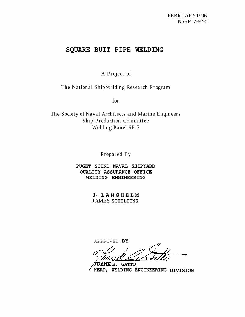
NSRP 7-92-5
THE NATIONAL SHIPBUILDINGRESEARCH PROGRAM
SQUARE BUTT PIPE WELDING
A PROJECT BYPUGET SOUND NAVAL SHIPYARD
FOR
THE WELDING PANELSP-7
FEBRUARY1996NSRP 7-92-5
SQUARE BUTT PIPE WELDING
A Project of
The National Shipbuilding Research Program
for
The Society of Naval Architects and Marine EngineersShip Production Committee
Carbon Steel Test Destructive ResultsStainless Steel Destructive Test ResultsNickel Copper Destructive Test ResultsCarbon Steel Weld Chemical AnalysisStainless Steel Weld Chemical Analysis70/30 Nickel Copper Weld Chemical Analysis70/30 Copper Nickel Weld Chemical AnalysisInconel 600 Weld Chemical AnalysisPoor Welding Stainless Steel ChemicalAnalysisGood Welding Stainless Steel ChemicalAnalysisMore Good Welding Stainless Steel ChemicalAnalysesPoor Welding Carbon Steel Chemical AnalysisMarginal Welding Carbon Steel ChemicalAnalysisAdditional Good and Marginal Welding CarbonSteel Chemical AnalysesCarbon Steel Destructive Test ResultsStainless Steel Destructive Test ResultsMonel Destructive Test ResultsWelding Data Sheet #123 For WeldingCarbon Steel PipeWelding Data Sheet #523 For WeldingStainless Steel PipeWelding Data Sheet #723 For WeldingNickel Copper PipeCarbon Steel Square Butt AMI SettingsStainless Steel Square Butt AMI SettingsWall Fusion Cross Sections
ii
NATIONAL SHIPBUILDING RESEARCH PROGRAM
SP7 - WELDING
Project Title: Square Butt Pipe Welding
Task Number: 7-92-5
Purchase Order Number: 9757-0031
Project Team: Frank B. Gatto, Head Welding EngineeringJames B. Langhelm, Welding Engineering TechnicianJames G. Scheltens, Welding EngineerLonnie Ince, Process Development WelderMike Nennemann, Welder
The main objective of this project was the development of weldingtechniques and procedures to economically weld fabricate pipe.X-ray quality full penetration square butt weld joints wereexpected. Significant cost savings can be achieved through thereduction in pipe fitting and welding man-hours by utilization ofa saw cut square butt joint design. The investigation of thevarious weld techniques and joint configurations are detailed inthis final report to the National Shipbuilding Research Program’sSP-7 committee on Welding.
SQUARE BUTT PIPE WELDING PAGE 2
Background:
The square butt joint design (Figure 1) is a weld jointwhere the pipe is butted together without a bevel. This type ofjoint design is easily prepared without a machine or hand groundbevel.
SQUARE BUTT JOINT WITHOUT INSERT
S A W C U T O R M A C H I N E D P R E P A R E D
P I P E W A L L T H I C K N E S S
FIGURE 1
In thin wall tubing applications (< 0.125” wall thickness)automatic orbital gas tungsten arc welding ( GTAW) machinesroutinely weld squre butt joint tubing for a variety ofcommercial applications and materials. An example is Wellons inSherwood, Oregon, a manufacturer of boilers and kilns. Wellonsroutinely welds plain carbon and stainless steel piping 1“ to 3“OD with wall thickness up to 0.140”. Over 120,000 square buttjoints have been welded using a Dimetrics Inc. “Centaur III,Portable Model 150 PTW” computer controlled orbital tube weldingsystem with “Model 5000 Series Heads”. The pipe is single passwelded to meet the ASME Boiler and Pressure Vessel Code, SectionIII for low pressure piping. These pipe welds have controlledpipe wall thickness of plus or minus 0.003” and square butt jointfit-up of 0.0 to 0.010” gap. The welds are autogenous and asecond manual filler pass is added only if excessive concavity isvisually found. Mismatch of 25% wall thickness can be welded butan additional weld pass may be needed to fill concavity.
Norfolk Naval Shipyard has qualified up to 0.147” wallthickness for GTAW on P-2 Copper Nickel piping single layer.Work by Puget Sound Naval Shipyard (PSNS), Welding EngineeringDivision successfully demonstrated six inch diameter, 0.250” wallthickness square butt one pass welds with no filler material inthe horizontal rolled position. This project was undertaken toincrease the use of square butt welding for thicker wall pipe inthe fixed position and to evaluate field welding.
SQUARE BUTT PIPE WELDING PAGE 3
Technical Approach:
Four base materials commonly used in Naval pipe applicationswere chosen for this project. They are carbon steel (S-l), 304stainless steel (S-8), 90% 10% and 70% 30% copper nickel (s-34),and 70% 30% nickel copper (S-42, Monel) . TABLE I of MIL-STD-248groups the base materials equivalents by “S” number. Pipe wallthickness from 0.072” class 700 copper nickel up to 0.438”, 3inch schedule 160 stainless steel were weld tested. Three basicsquare butt weld joint designs were evaluated: square end withoutinsert (see Figure 1), square end with insert (Grinell style) anda modified square end butt with a 45 degree V-groove for wallthickness 0.250” and greater (see Figure 2) . The weld testjoints were prepared by machining or were used in the as saw cutcondition. Root gaps up to 0.300” and mismatch up to 25 percentof the wall thickness were tested to evaluate fit-up toleranceeffect on weldability.
Automatic and manual pipe welds were evaluated for squarebutt joint design. Automatic welding was performed with an ArcMachine Inc. (AMI) system on a Model 15 and 81 weld heads.Manual welding utilized a Miller Arc-Pak 350 with a Tig-Rig 2Scontroller and Digi-Meter 600 amperage and volt meter. Pulse arcand steady arc schedules were evaluated on both manual andautomatic.
In addition to the above elements, three main weld variableswere evaluated for successful thick square butt welds: 1) Pulsepurge versus steady purge, 2) 95% Argon 5% Hydrogen versus 100 %Argon shielding gas, 3) Blunt tungsten electrode versus four toone tapered tungsten electrode.
After all evaluations of weld techniques for square buttpipe welding, weld procedures were developed for carbon steel,stainless steel and Monel. These procedures have been submittedto NAVSEA 03M2 for approval.
Test Results and Evaluations :
Manual:
Joint Design EvaluationsThe initial evaluations and tests were conducted from July
1993 to July 1994. Three weld joint designs were manually weldevaluated on the four selected base materials; carbon steel, 304stainless steel, 70% 30% Monel and 90% 10% and 70% 30% coppernickels. Figures 1 and 2 depict the typical joint designs usedin these early trials. A fourth joint design, a self aligningmodified square butt with 10 degree bevel was used successfullyin place of the straight square butt (see Figure 3) . This 10degree bevel joint design reduced mismatch and self aligned the
SQUARE BUTT PIPE WELDING PAGE 4
SQUARE BUTT JOINT WITH INSERT
R I N G T H C K N E S S = 1 / 1 6 -
PIPE WALL THICKNESS SAW CUT OR MACHINED PREPARED
MODIFIED SQUARE BUTT JOINT
A ROOT GAP = 0.000 To 0.030’”
WITH OR WITHOUT AN INSERTPIPE WALL THICKNESS (T)
SAW CUT OR MACHINED PREPARED
FIGURE 2
two pipe segments but was not pursued further in this study dueto the need for machine preparation for this joint. Initialtrials also showed no advantage in pipe wall weld penetrationfor: Machine preparation on straight square butt; Square buttwith insert versus plain saw cut; or Deburred end preparation.An insert square end butt pipe wall weld penetration was the sameas straight square end butt welds. For carbon steel and stainlesssteel maximum through wall thickness producing satisfactoryinternal weld contour was 4“ inch schedule 40, 0.237” wallthickness.
SQUARE BUTT PIPE WELDING PAGE 5
10° SQUARE BUTT JOINT DESIGN
R O O T G A P = 0 . 0 0 0 ” - 0 . 0 3 0 ”
PIPE WALL TRICKNESS
Figure 3
ibis was true for all machined or saw prepped pipe, whether with
a 10 degree bevel, a straight square end or a square butt with
use of a bevel joint design (depicted at the bottom of Figure
2) . For Monel, the maximum pipe wall thickness satisfactory both
for visual and cross sectioning, was 2“ schedule 40, 0.154” wall
thickness. Through weld penetration up to 0.180” was possible on
copper nickels, no cross sections were satisfactory due to fusion
l i n e p o r o s i t y . T h i s p r o b l e m i s d i s c u s s e d u n d e r m a t e r i a l
v a r i a t i o n s .
Sinqle Pass Versus Two Pass Welds
The joint design used was found to affect the number of
passes required to complete a weld. Square end machined joints
with no gap and minimal mismatch needed only one pass to achieve
satisfactory weld contour and X–ray satisfactory welds. S q u a r e
end saw cut joints resulted in fit up end gaps and mismatch that
required two pass welds to achieve satisfactory weld contour.
This is a root pass with through wall fusion and a cover layer.
If properly fit–up square end pipe with an insert, machined
or saw c u t p i p e w e l d j o i n t s r e q u i r e d o n l y o n e p a s s f o rsatisfactory weld contour and X-ray quality. Minimal test work
on square end with an oversized insert and the 10 degree bevel
s e l f a l i g n i n g j o i n t p r o d u c e d s a t i s f a c t o r y s i n g l e p a s s w e l d
contours. Two passes were required on the thick wall bevel
joints tested to fill in the bevel and provide sufficient weld
r e i n f o r c e m e n t .
SQUARE BUTT PIPE WELDING PAGE 6
Based on the economics of the cost of manufacturing inserts,
machining end preps versus weld time of two pass welds over one
pass it was decided to concentrate further tests on two pass, saw
cut and deburred joint design only. Also it was anticipated that
m o s t f i e l d w e l d s w o u l d n o t f i t u p a s c l o s e l y a s n e e d e d t o
g u a r a n t e e s a t i s f a c t o r y s i n g l e p a s s f i n i s h e d w e l d s . P S N S p i p e
weld applications are made to MIL-STD-278 which require two pass
welds on high temperature and pressure weld joints. Though for
s o m e a p p l i c a t i o n s s i n g l e p a s s w e l d s m a y b e s u f f i c i e n t , t h e
direction for the balance of the program was directed to qualify
MIL–STD–278 and MIL-STD-248 weld procedures.
T u n g s t e n S h a p e
A 90 degree included angle blunt, t u n g s t e n e l e c t r o d e w a s
f o u n d t o e n h a n c e t h e d e p t h o f t h e w e l d p o o l p e n e t r a t i o n a s
compared to the 4 to 1 taper tungsten tip that is normally used
for GTAW (see Figure 4). The fan shaped arc plasma produced by
the 4 to 1 tapered tungsten is inclined to enlarge the size of
t h e w e l d p o o l a n d d i m i n i s h i t s d e p t h o f p e n e t r a t i o n .
Concentration of the arc heat with the tapered tip requires a
very short arc length, increasing the potential for the tungsten
tip to come in contact with the weld pool. The shaft shaped arc
p l a s m a p r o d u c e d b y t h e b l u n t t u n g s t e n t i p w a s f o u n d t o i m p r o v e
t h r o u g h w a l l f u s i o n d u e t o t h e m o r e -c o n c e n t r a t e d a r c h e a t ,
without the necessity of an excessively short arc length.
TUNGSTEN TIP SHAPES
Figure 4
..- .
SQUARE BUTT PIPE WELDING PAGE 7
Shielding Gas95% Argon with 5% Hydrogen was used as a torch shielding gas
because of its capacity to improve the depth of weld poolpenetration compared to 100% argon. It also intensified the heatof the arc so that lower amperages, 15 to 20 percent less thanwith 100% Argon, were needed to penetrate the same pipe wallthickness. This decreased amperage also reduced the heat inputto the general weldment resulting in a smaller heat affected zoneand more rapid cooling. Photograph 1 (see Attachment 23)compares the through stainless steel pipe wall fusion crosssections of 4 to 1 tapered tungsten using 100% Argon to blunttungsten tip weld sections using 95% Argon with 5% Hydrogen, atvarious pipe wall thicknesses. The combined beneficial effectsof blunt tungsten tip electrodes and 95% Argon with 5% Hydrogenproduced a narrower, straighter weld root bead.
Maximum pipe wall thickness for carbon steel and stainlesssteel producing acceptable results using 100% Argon was 0.150”.The increased weld amperage required for greater wall thicknessresulted in excessive heat buildup and produced unsatisfactoryinternal weld contour.
95% Argon with 5% Hydrogen improved the weld puddleproperties of copper nickel and nickel copper, making their weldsmore like stainless steel and produce acceptable weldments to agreater depth or larger wall thicknesses. However 95% Argon with5% Hydrogen shield gas did result in fusion line porosity incopper nickel welded pipe joints.
Pulse PurgeWhen welding with steady current GTAW, a purge with an inert
atmosphere is necessary for full wall thickness root fusion. Thequality of the purge gas on the root face of the molten pool is akey element in producing a satisfactory pipe butt weld. Purgequality is determined by the purity of the purge gas, void ofoxygen and moisture, and control of internal pressure isaccomplished by proper inlet flow and exit orifice size.
Initial through wall fusion is visually detectable with asteady purge, but these visual characteristics quickly disappearas the weld pool is progressed. For carbon and stainless steelduring weld pool formation with 95% Argon with 5% Hydrogenshielding gas, the arc plasma will rotate in a slow circularmotion. This circular movement stops and the arc stabilizes whenthrough wall fusion occurs. During subsequent welding the arcremains motionless and gives no clue to whether or not throughwall fusion is occurring.
During weld pool formation welding copper nickel or nickelcopper pipe with 95% Argon and 5% Hydrogen shielding gas, theweld pool is slightly convex. When through wall fusion doesoccur the convex surface changes to a slightly concave surface.During subsequent welding the surface remains concave giving nohint of successful through wall fusion.
SQUARE BUTT PIPE WELDING PAGE 8
The thicker root land of square butt pipe weld joints wasfound to need a better method to determine through wall fusion,especially in the fixed horizontal welded pipes. Pulsed purgingprovided the manual welder with a positive indicator of whenthrough wall fusion occurred throughout the weld progression.
Pulse purge is a modification of the normal purge processwhere a solenoid or mechanical valve is used to introduce throughflow ofconstantsolenoidpressurea normal
the purge gas into the inner pipe. Rather than aflow and pressure in a normal straight purge, theor mechanical valve is opened and closed, creating awave that travels through the purge pipe system. Wherepurge at pressures greater than 0.5 inches of water as
measured, with a Magnehelic Gage, may result in excessive rootconcavity, the peak pressure of the pulsed purge wave reaching2.5 inches of water will result in satisfactory root contours.When the weld pool has fully penetrated the pipe wall, it willmove in and out in response to the changing internal pressure asthe pressure wave passes through the pipe. This motion is easilyvisible to the welder or an observer and serves as a positiveindicator of full weld bead penetration of the pipe wall. If theweld pool stops pulsing it signals the welder to stop forwardprogression until pulsing of the weld pool restarts, at whichtime forward weld progression can continue. In the horizontalfixed position the pulse purge is varied as pipe root weld beadsegments are welded around the circumference. Low pulse purgepressure peaks are used on the pipe bottom and high peakpressures are used on the top of pipe welded in the horizontalfixed position.
The optimum pulse purge determined in earlier studiesconsist of a pulse time of 125 milliseconds with a pulse ratebetween 2 and 3 cycles per second. Figure 5 depicts a typicalpulse purge arrangement. As this project developed the pulsepurge generator was replaced by an inexpensive mechanical switchsystem built by the Dwight Company called the “Root Hog, WeldRoot Purge Gas Device”.
Pulse Current ArcPulse current allows intermittent use of elevated amperages
to improve weldability of pipe. It maintains acceptable weldcontour while maximizing penetration in the horizontal fixedposition. Successful welds were made on up to 0.216” wallthickness for carbon and stainless steel pipe. But the pipethickness and fit-up had to be consistent for controlled timingwelding. Weld pool characteristics with pulse arc will notindicate through wall fusion.
Pulse purging was found to be ineffective with pulsecurrent. The momentary elevated amperage pulse intensified theweld pool action, masking the distinguishing characteristics ofthe pulse purge for determining when through wall fusion hasoccured.
SQUARE BUTT PIPE WELDING PAGE 9
TYPICAL PULSE PURGE ARRANGEMENT
/ ROOT PASS \
ARGON PURGE OUT
Square Butt DataBased on the early evaluations a series of test pipe welds
were made to determine the limits of square butt welding. TableI lists the “Manually Welded Square Butt Test Matrix”. All pipejoints were stainless steel brushed or emery wheel cleaned ofoxide and tack welded. A purged GTA seal weld pass was madecircumferencially to make the joint air tight. Minor amounts offiller material were added to the seal pass when joint fit-up gapexceeded 0.030”. A typical time to seal pass a 2“ schedule 80carbon steel joint was 3 minutes. Joints with large root gaps,exceeding 0.125”, required larger amounts of filler material toseal. All pipe joints were GTAW in the horizontal fixed positionpipe, vertical weld (5G) position using 95% Argon with 5%Hydrogen and a 90 degree blunt tungsten electrode. All weldswere evaluated visually after the root pass for acceptableexternal weld and root contour. Large root gaps and thicker walljoints required one cover pass to achieve acceptable weldreinforcement.
SQUARE BUTT PIPE WELDING PAGE 10
TABLE I
MANUALLY WELDED SQUARE BUTT TEST MATRIX
SQUARE BUTT PIPE WELDING PAGE 11
NOTES FOR “MANUALLY WELDED SQUARE BUTT TEST MATRIX”
1.
2.
3.
4.
5.
6.
7.
8.
9.
10.
Data in columns referencing this note relates to weldsmade with a Steady Arc (SA) constant current, PulsingPurge (PP) and 95% Argon with 5% Hydrogen shielding gas(95/5) . This column documents the weld amperage used(i.e. 52A) and the peak pulse pressure measured in“inches of water” (i.e. 1.2) .
Data in columns referencing this note relates to weldsmade with a Steady Arc (SA) constant current, SteadyPurge Flow (SP) and 95% Argon with 5% Hydrogenshielding gas (95/5) . This column documents the weldamperage used (i.e. 56A) and the constant purgepressure used in “inches of water”.
Data in columns referencing this note relates to weldsmade with a Pulsing Arc (PA) pulsing current, SteadyPurge Flow (SP) and 95% Argon with 5% Hydrogenshielding gas (95/5) . This column documents theaverage weld amperage used (i.e. 55A) and the Arc Pack350 Pulse Control Program Number (i.e. 3). Programnumber 3 requires a peak amperage of 69 amps (peak timeof .80 seconds and background time of .53 seconds) to
average 55 amps.
This weld was made using a 1/16” square ended tungsten.
These settings were used on a weld that passed X-Rayand destructive testing.
These settings were used on weld joints that had a 45°bevel and a 0.200” root face. One used a flat insertand the other used no insert.
Full penetration could not be achieved on this wallthickness.
This weld was made using a 1/16” 90° blunt tungsten.
Unless otherwise noted, all welds were made using a3/32” 90° blunt tungsten.
All welding was done in the horizontal fixed position.
Material EffectsCarbon steel and stainless steel pipe joints welded equally
as well. The only significant difference between the twomaterials was that carbon steel required about 15 percent morewelding amperage. Manual welding of the square butt design, with
SQUARE BUTT PIPE WELDING PAGE 12
or without inserts, was satisfactory for up to 0.218” wallthickness on both material types. Through wall fusion wasattainable with steady arc both pulse purge and straight purge,and with pulsed arc with steady purge. Consistent andpredictable results could only be obtained with the pulse purgewelded joints. The use of consumable inserts in carbon steel andstainless steel joints had no visual beneficial effects on weldquality or penetration.
The modified 45 degree square butt joint used on stainlesssteel pipe, allowed through wall fusion on pipe wall thicknesses0.250” and greater. Even with this modified 45 degree squarebutt joint, fused wall concavity was prone to occur on wallthicknesses greater than 0.300”, which necessitated added fillerwire on the cover pass.
Autogenous manual welds performed on 70% 30% and 90% 10%copper nickel produced visually acceptable weld face and rootsurfaces, but radiographic testing and cross sections disclosedsubsurface porosity. Use of consumable MIL-67 copper nickel andMIL-60 nickel copper inserts resulted in less porosity but didnot eliminate the porosity especially in the weld base metalinterface. The thermal conductivity of copper nickel alloysprevented through wall fusion with the square butt joint beyond0.150” wall thickness.
The limited test work conducted on Monel found it to performbetter than copper nickel alloys but not as well as carbon orstainless steel. The maximum depth of penetration ofsatisfactory welds was 0.154”.
Test Matrix Testinq ResultsAll visually acceptable Monel, carbon steel and stainless
steel welds were liquid dye penetrant tested satisfactory.Liquid penetrant tests were performed in accordance with MIL-STD-2035, Class 1. The copper nickel weld joints displayed roundedindications. Several square butt joints were submitted forradiographic evaluation to MIL-STD-2035, Class 1:
Two 90/10 copper nickel pipe, one autogenous and one with aconsumable insert, 5“ Class 200 (0.109” wall thickness),tested unsatisfactory due to rounded porosity and pipeporosity.
SQUARE BUTT PIPE WELDING PAGE 13
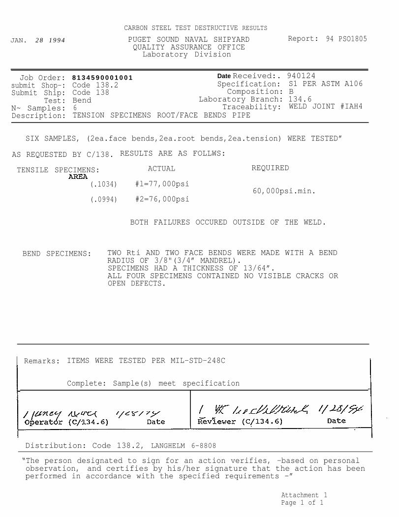
The satisfactory radiographic test samples were destructivetested per MIL-STD-248C and compared to their base materialspecification. Results are attached (Attachments 1,2 & 3) andsummarized below.
Carbon steel; Two root and two face bend tests satisfactorywith no visible cracks or open defects. The two tensiletests were satisfactory with failure outside the weld area.
Stainless steel; Two root and two face bend testssatisfactory with no visible cracks or open defects. Thetwo tensile tests were satisfactory with failure in the weldarea.
70/30 Nickel copper; Two root and two face bend testssatisfactory with two samples, one face and one root,displaying small acceptable fissures. The one tensile testwas satisfactory with the fracture running across the weldarea from and into the opposite base material.
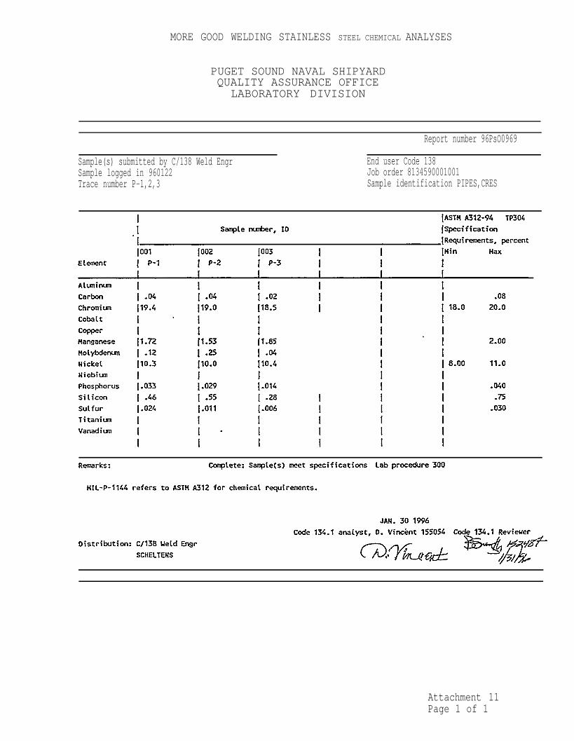
and effects on weld properties were investigated. As shown abovedestructive tensile and bend results were acceptable for plaincarbon steel, stainless steel and Monel pipe weldments. Thefracture of stainless steel in the weld could be expected sincethe remelted annealed stainless pipe weld would have a slightlylower yield strength than the wrought pipe structure. Autogenousweld chemistry was compared to the adjoining pipe base materialon five pipe materials; carbon steel, stainless steel, Monel, 70%30% copper nickel and Inconel 600. Attachments 4 through 8 givethe chemical analysis of the autogenous weld, the adjacent pipeand the base material specification chemistry. No significantchemical changes were observed.
During final weld procedure qualifications one heat ofstainless steel pipe and one heat of carbon steel pipe weldedsignificantly different from all other heats tested until thattime. Though these two heats did weld successfully the time forthe weld to penetrate the wall was three times as long as otherheats of material with the same wall thickness. The weld poolactivity described earlier in the Pulse Purge section for carbonand stainless steels was absent from the start of the weld pool.The resulting arc did not maintain a narrow plasma but enlarged
with a growing weld pool Size. This resulted in poorerpenetration and wider finished weld beads.
In the AMI General Guidelines for Fusion Welding, Rev. July,1991, Section “Variations in weld penetration in different heatsof stainless steel:” discusses this phenomenon extracted fromBurgardt and Heiple, 1986. The direction of flow in the weldpuddle is believed to be fundamentally different in low sulfurheats, 0.001-0.007% (or low oxygen to a lesser extent) than when
iSQUARE BUTT PIPE WELDING PAGE 14
some sulfur is present. The direction of fluid flow is outwardsand thus the puddle is wide and shallow. In normal sulfurcontent heats, 0.008-0.030% the fluid flow is inward and downresulting in deeper weld bead penetrations.
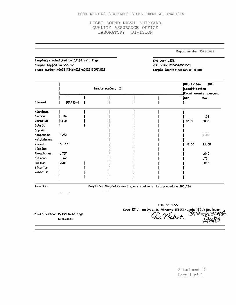
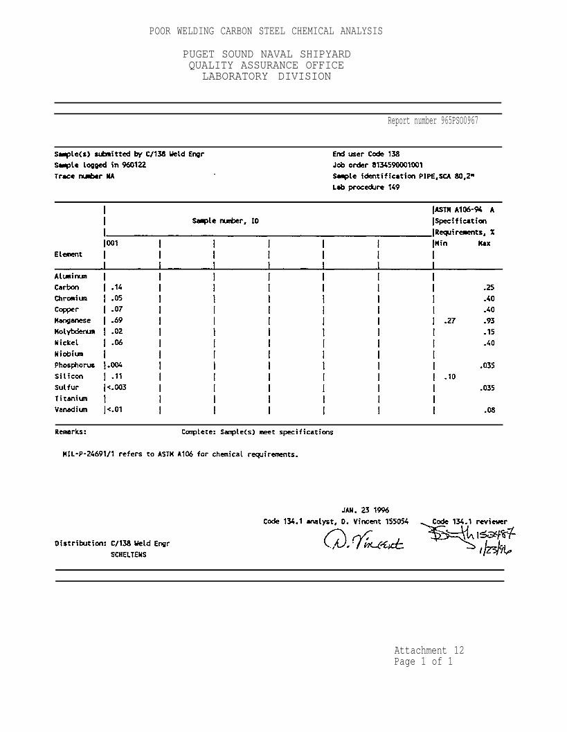
Chemistries for the poor acting heats were compared tonormal weldable pipe heats that penetrated easily. The one poorwelding heat of stainless steel pipe had the same typicalchemistry as the normal welding pipe heats~ except it had only0.001% sulfur. The one pipe heat of carbon steel that weldedpoorly tested <0.003% sulfur. One marginal weldable heat ofcarbon steel tested 0.004% sulfur. All normal welding pipe heatsof carbon and stainless steel had at least 0.007% sulfur.Attachments 9 through 14 are the full chemical analyses for thepoor and marginal weldable pipe heats and a typical chemistriesof good weldable pipe heats for carbon and stainless steel.
To demonstrate this sulfur effect on welding, a single weldbead on pipe wall was run on a low sulfur(<O.003%) content carbonsteel pipe and a normal sulfur (0.023%) content pipe. The heatinputs were the same. All parameters were consistent. Amperage,voltage hold start time and travel speed were identical.Photograph 2 shows the surface weld bead difference between thelow sulfur carbon steel pipe and the normal sulfur carbon steelpipe. Photograph 3 is the low sulfur content pipe weld profileand Photograph 4 is the normal sulfur content pipe. The lowsulfur content carbon steel pipe results in a wide non-penetrating weld bead and the normal sulfur carbon steel piperesults in a narrow penetrating weld bead under the sameconditions.
WELD BEAD SURFACELOW SULFUR (<0.003%) NORMAL SULFUR (0.023%)
Photograph 2
SQUARE BUTT PIPE WELDING PAGE 15
LOW SULFUR WELD BEAD PROFILE
Photograph 3NORMAL SULFUR WELD BEAD PROFILE
Photograph 4
The effect of sulfur content in the base pipe materialappears to be a major factor in time to penetrate the wallthickness in welding and the resulting weld bead width. Onlyextremely low sulfur contents, <0.004% sulfur, affect weldquality for the manual square butt pulse purge techniquesqualified because of their flexibility. As discussed later inthe report, this sulfur content effect on penetration timingprevents consistent weld techniques for automatic thick wallsquare butt welding.
SQUARE BUTT PIPE WELDING PAGE 16
Manual Weld Procedure QualificationsThree sets of manual pipe weld procedure qualifications were
welded and tested to MIL-STD-248C (also meets MIL-STD-248E andS9074-AQ-GIB-O10/248 Rev. O requirements) . Carbon steel,stainless steel and Monel pipe materials were square butt weldedusing pulse purge. All pipe joints were saw cut, stainless steelbrushed or emery wheel cleaned of oxide and tack welded. Apurged GTA seal weld pass was made circumferencially to make thejoint air tight. Filler material was added to the seal pass whenthe joint fit-up gap exceeded 0.030”. The time to make this sealpass was less than 3 minutes. All pipe joints were GTAW in thehorizontal fixed position pipe, vertical weld (5G) position using95% Argon with 5% Hydrogen torch gas and a 90 degree includedangle blunt tungsten electrode for the root and seal pass. Afour to one taper tungsten electrode was used with fillermaterial on the cover pass. For the seal and cover pass astraight inner pipe Argon purge was used. For the root pass thepulse purge was utilized as described earlier in the report.Four 2" Schedule 80 pipe assemblies for carbon steel andstainless steel were welded and tested for the procedurequalifications. Three 2“ Schedule 40 Monel pipes were welded forprocedure qualifications.
Al 1 test assemblies were visually inspected to PSNSIndustrial Process Instruction (IPI) 0074-905 Rev. A forcompliance with pipe classes P-1 and P-2 for MIL-STD-278 and MIL-sTD-248c requirements. All were satisfactory, meeting the weldreinforcement, convexity and concavity requirements for bothinner and outer surfaces. The carbon steel pipe assemblies weremagnetic particle inspected while the stainless steel and Monelpipe assemblies were liquid penetrant inspected per MIL-STD-2035,Class 1. All assemblies were satisfactory. Finally all pipeweld assemblies were radiographed per MIL-STD-2035, Class 1. Al 1pipe weld assemblies radiographed satisfactory.
As per MIL-sTD-248, two of the 2“ pipe weld assemblies fromeach material type were tensile tested as full pipe weldassemblies. In addition a third assembly was sectioned toprovide two face bends, two root bends and two macro samples.Fourth assemblies were sectioned for samples. All tensile, bendtests and macros were satisfactory and meet the requirements ofMIL-STD-248C and MIL-STD-278. For the stainless steel, twoadditional root bend samples were tested satisfactory per MIL-sTD-248C requirements for corrosion sensitivity per Practice E ofASTM A262. Attachments 15, 16 and 17 report the destructivetesting results summarized above.
For carbon steel and stainless steel a matrix of additionalpipe sizes and wall thicknesses were prepared as the 2“ diameterpipe assemblies and welded to determine the full range of weldingamperages for various wall thicknesses. Root openings werevaried from 0.0 up to 0.125”. Filler metal was added to the sealpass with root gaps exceeding 0.030”. All test assemblies werevisually inspected to PSNS Industrial Process Instruction (IPI)
SQUARE BUTT PIPE WELDING PAGE 17
0074-905 Rev. A for compliance with pipe classes P–1 and P-2 for MIL-STD-278 and MIL-STD-248C requirements. All weresatisfactory, meeting the weld reinforcement, convexity andconcavity requirements for both inner and outer surfaces. Thecarbon steel pipe assemblies were magnetic particle inspectedwhile the stainless steel pipe assemblies were liquid penetrantinspected per MIL–STD–2035, Class 1. All assemblies weresatisfactory. Finally, all pipe weld assemblies wereradiographed per MIL-STD-2035, Class 1- All pipe weld assembliesradiographed satisfactory. Pipe assemblies with mismatch of pipewall fit-up exceeding 25% of the wall thickness were also welded.These mismatch square butt weld assemblies were visuallyacceptable and cross sectioned to confirm contour acceptability.Photograph 5 shows the profile and cross section of a typicalroot pass on a 40% mismatch square butt joint.
Attachments 18, 19 and 20 summarize the square butt, pulsepurge pipe weld procedures submitted to NAVSEA for approval forcarbon steel, stainless steel and Monel pipe materials.Photographs 6, 7 and 8 are etched cross sections of thequalification pipes showing the root pass (and its consumption ofthe seal pass) and the cover pass.
40% MISMATCH ASSEMSLY CARBON STEEL
Photograph 5 Photograph 6
SQUARE BUTT PIPE WELDING PAGE 18
STAINLESS STEEL MONEL
Photograph 7 Photograph 8
Automatic:
A limited number of automatic square butt weld assemblies weremade. All square butt pipes were welded with an Arc Machine Inc.Orbital welder. The AMI welder maintains the tungsten electrodearc length through utilization of an Automatic VoltageControl(AVC) function. When the pulse purge was used with theAMI welder the pulsating weld pool would cause instanttermination of the arc when the tungsten electrode contacted theweld pool. The AVC sustaining the arc length could not reactquickly enough to the weld pool movement. For this reason allautomated pipe welds utilized a steady purge with a pulsedcurrent. Initial evaluations, run on the AMI Model 15 head,found as in manual welding that 95% Argon with 5% Hydrogenshielding provided deeper penetration than 100% Argon. Both a 4to 1 taper design and a blunted 90 degree tungsten electrode wereevaluated.
All first trial test welds used the 95% Argon 5% Hydrogenshield gas and the blunt 90 degree tungsten electrode. Table II“AMI Square Butt Data Chart list the joint types and settingsthat produced visually satisfactory pipe welds. All were singlepass welds with either with an insert or no insert square buttjoint design (see Figure 6) welded in the horizontal pipeposition (5G). Root gap fit–up was tighter than manual and pipewall mismatch were minimized for consistent weld penetration.
.- .
SQUARE BUTT PIPE WELDING PAGE 19
TABLE
AMI SQUARE BUTT
I I
DATA CHART
NOTES :
1.
2.
3.
4.
5.
Each space on the chart represents a test weld.
All Jt 1 & Jt 2 welds will be made on a saw cut square buttweld end prep, see Figure 9. Two consecutive welds will bemade on this end prep to confirm repeatability of weldresults.
Jt 3 welds will be made on a saw cut square butt weld end prepwith a 1/16” thick flat consumable insert with a depth equalto or slightly greater than the wall thickness of the testpipe, see Figure 9.Data entries in each space will document welding results.Acceptable tests will list the weld amperage (primary amps andbackground amps [i.e. 155/45] ) and the travel speeds ininches per minute (slowest to the fastest [i.e. 5.3 - 6] )that were used.
All welding will be done in the horizontal fixed position,unless otherwise noted.
SQUARE BUTT PIPE WELDING PAGE 20
AUTOMATIC SQUARE BUTT JOINT DESIGN
PIPE WALL THICKNESS
JOINTS #1 AND # 2
PIPE WALL THICKNESS
JOINTS #3
FIGURE 6
SQUARE BUTT PIPE WELDING PAGE 21
A pulsing arc operating in the “step mode” was utilized. Inthe step mode, the torch moves ahead while on the backgroundcurrent and remains stationary while on the primary currentsetting. Typical schedules for carbon and stainless steel pipewelds are attached (see Attachments 21 and 22). Amperagesettings would remain constant around the circumference of thepipe weld and the travel speed varied during weld progression tocompensate for weld bead position and heat buildup. The internalroot contour of these weld joints is slightly convex on the top(less than 1/16”) and slightly concave on the bottom (less than1/16”) . The working range of parameters (primary amperage,background amperage and travel speed) narrows to produceacceptable internal root contour as the wall thickness increased.
The first trial set produced acceptable square butt weldjoints but was obtained on pipes with consistent wall thicknessand fit-up tolerance. As in square butt manual welding, a weldprocedure qualification test series was attempted. Two inchschedule 40 stainless steel pipe with a nominal wall thickness of0.154” was selected as the first and most likely qualificationcandidate.
The heat chemistry of the schedule 40 stainless steel pipewas extremely low sulfur (0.001%) . As discussed in the manualpipe weld chemistry effects, this low sulfur chemistry resultedin weld beads that were wide and shallow. Through penetrationtime was inconsistent and no single weld schedule would giveacceptable weld contour and penetration.
Additional heats of stainless steel pipe were successfullywelded without shallow penetration problems but the schedulesdeveloped varied with each heat of material. As discussed in thebackground section, Wellons controlled seam welded pipe wallthickness to plus or minus 0.003” and square butt joint fit-upfrom 0.0 to 0.010” gap. With these tight tolerances theautomated schedule was divided into seven weld power and speedcontrol segments that vary only 3% in magnitude. Puget SoundNaval Shipyard (PSNSY) uses seamless pipe with a larger variancein wall thickness. Pipe joint fit-up tolerances at PSNSY aregenerally allowed up to 0.030”. It was determined that for agiven heat chemistry, consistent wall thickness and a machinedfit-up, less than 0.015” gap, a automated weld schedule for theAMI could be made. But a general schedule for all heat lots withvarying chemistry, varying wall thickness and non-machinedtolerances could not be developed for production welding of thicksquare butt joints.
Discussion:
A technique for manually welding square butt thick pipesections up to 0.250” was developed. The use of pulse purge wasnecessary in order to ensure complete penetration with noexcessive concavity or convexity. The pulse intensity was variedfor horizontal fixed pipe joints around the perimeter. For
SQUARE BUTT PIPE WELDING PAGE 22
vertical fixed and horizontal roll positions the pulse need notbe varied in intensity.
The economic advantages of using pulse purge square butt aremany. First the joint preparation time of saw cut versus cut andangle machine or grind is an order of magnitude in time. Thecost of the pulse purge unit (<$200) is much cheaper than thetools or machinery for end preparation on conventional joints.No insert costs and the reduction of filler material needed alsoreduces costs. The total weld time for a typical 2 schedule 80joint with seal, root and cover pass is one half hour includingcool down time between segments. Fit-up time could be reduced aswell due to the looser fit-up tolerances of the square butt jointthan an insert joint. A conventional plain carbon v-grooveinsert joint fit-up and weld is allotted 4.2 hours by PSNSYstandards. A reduction of one to two hours would be expected ifthe square butt joint design were substituted. With reduced weldtimes consumption of purge gas would also be reduced.
The time to retrain pipe welders to use pulse purge wasfound to be less then one day. After welding several practicejoints, the visual observation of the pool pulsing and slowerroot pass was learned. The time to train new pipe welders shouldbe reduced over conventional pipe joints, since the pulse purgetechnique relies on visual observation only and not time countingor experience for various materials, thicknesses and jointconfigurations.
Conclusions:
Acceptable manual thick section square butt pipe welds canbe made in carbon steel, stainless steel and Monel basematerials. Welded copper nickel pipe base materials producedunacceptable defects in the fusion line and could not passnondestructive testing (i.e. porosity) . Carbon steel, stainlesssteel and Monel could be square butt welded up to 0.154” with or‘without an insert with 100% Argon shield gas and an inner pipepurge. The use of a inner pipe pulse 100% Argon purge and 95%Argon 5% Hydrogen shield gas allowed consistent acceptable pipewelding for carbon and stainless steel up to 0.250” pipe wallthicknesses. Thicker sections could be welded with a modified 45degree bevel square butt joint. Square butt joints with weldfit-up gaps up to 0.250” and wall mismatch up to 25% weresuccessfully welded with the pulse purge technique. The effectof base material sulfur content was found on the time topenetration the pipe wall; resulting in increased bead width andpoor weld root contour.
Manual squrarebutpulseslse purge weld procedures for carbonsteel and stainless steel pipe up to 0.250”, and Monel pipe up to0.154” were qualified per MIL-STD-248 and MIL-STD-278 latestrevisions. Automatic procedures were not consistent due tovarying wall thickness and sulfur chemistry effects on time forthrough wall penetration.
SIX SAMPLES, (2ea.face bends,2ea.root bends,2ea.tension) WERE TESTED”
AS REQUESTED BY C/138. RESULTS ARE AS FOLLWS:
TENSILE SPECIMENS: ACTUAL REQUIRED
(.1034) #l=77,000psi60,000psi.min.
(.0994) #2=76,000psi
BOTH FAILURES OCCURED OUTSIDE OF THE WELD.
BEND SPECIMENS: TWO Rti AND TWO FACE BENDS WERE MADE WITH A BENDRADIUS OF 3/8"(3/4” MANDREL).SPECIMENS HAD A THICKNESS OF 13/64”.ALL FOUR SPECIMENS CONTAINED NO VISIBLE CRACKS OROPEN DEFECTS.
I Remarks: ITEMS WERE TESTED PER MIL-STD-248C
Complete: Sample(s) meet specification
Distribution: Code 138.2, LANGHELM 6–8808
“The person designated to sign for an action verifies, -based on personalobservation, and certifies by his/her signature that the action has beenperformed in accordance with the specified requirements -”
SIX SAMPLES,(2ea.face bends,2ea-root bends,zea. tension) WERE
AS REQUESTED BY. C/138. RESULTS ARE AS FOLLOWS:
TENSILE SPECIMENS: ACTUAL REQUIREDAREA
(.1134) #1= 85,000psi
TESTED
75,000 psi min.(.1151) #2= 85,000psi
BOTH FAILURES OCCURED IN THE WELD.
BEND SPECIMENS: TWO ROOT AND TWO FACE BENDS WERE MADE WITH A BENDRADIUS OF 3/8”’(3/4” MANDREL).SPECIMENS HAD A THICKNESS OF 13/641’.ALL FOUR SPECIMENS CONTAINED NO VISIBLE CRACKS OROPEN DEFECTS.
Remarks: ITEMS WERE TESTED PER MIL-STD-.248C
Complete: Sample(s) meet specifications
Date
Distribution: Code 138-2, LANGHELM 6-8808
"The person designated to sign fOr an action Verifies, based on personalobservation, and certifies by his/her signature that the action has beenperformed in accordance with the specified requirements.”
Job order 8134590001001 Date received 950419Submit shop Code 138.2 Specification MILT23520Submit ship Code 138 Composition MISC
Test Tensile, Lab Proc. 005 Branch 134.6Num samples 1 Trace number WELD JOINT#EDH-4Description AUTOGENOUS PIPE WELD SAMPLE
THE PIPE WELD SAMPLE WAS TENSILE TESTED AS REQUESTED BY C/138,THE
RESULTS ARE AS FOLLOWS:
CROSS-SECTIONAL .ACTUAL U.T.SAREA1.116 81,500 psi
THE FRACTURE OCCURED IN THE UPPER
THE LOWER PIPE.
REQUIRED U.T.S. FOR THE PIPE
70,000 psi min.
PIPE RUNNING THROUGH THE WELD INTO
Remarks:
Complete: For information only
Distribution: Code 138.2, LANGHELM 6-8808
“The person designated to sign for an action verifies, based on personalobservation, and certifies by his/her signature that the action has beenperformed in accordance with the specified requirements.”
Sample(s) submitted by C/138 Weld Engr End user Code 138Sample logged in 960122 Job order 8134590001001Trace number P-1,2,3 Sample identification PIPES,CRES
Job order 8134590001001 Date received 960122Submit shop C/138 Weld Engr Specification MILP24691/1Submit ship Code 138 Composition 1
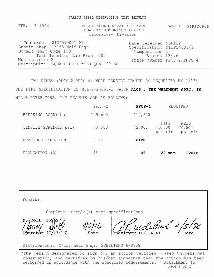
Test Tensile, Lab Proc. 005 Branch 134.6Num samples 2 Trace number PPCS-2,PPCS-4Description SQUARE BUTT WELD QUAL 2“ SC
TWO PIPES (PPCS-2,PPCS-4) WERE TENSILE TESTED AS REQUESTED BY C/138.
THE PIPE SPECIFICATION IS MIL-P-24691/l (ASTM
MIL-E-23765,70S2. THE RESULTS ARE AS FOLLOWS:
PPCS -2
BREAKING LOAD(lbs) 109,600
TENSILE STRENGTH(psi) 73,500
FRACTURE LOCATION PIPE
ELONGATION (%) 45
REQUIRED
110,200
PIPE WELD72,000 60,000 70,000
psi min psi min
PIPE
46 22 min 22min
Remarks:
Complete: Sample(s) meet specifications
I Distribution: C/138 Weld Engr, SCHELTENS 6-8808
"The person designated to sign for an action verifies, based On personal observation, and certifies by his/her signature that the action has beenperformed in accordance with the specified requirements. “ Attachment 15
Job order 8134590001001 Date received 960130Submit shop C/138 Weld Engr Specification MIL STD 248Submit ship Code 138 Composition CARBON STEEL
Test Multiple Tests Branch 134.6Num samples 6Description ROOT BENDS, FACE BENDS AND MACROS
TWO MACROS WERE EXAMINED AND EVALUATED IN ACCORDANCE WITH THE REQUIREMENTSOF Mil-STD-248C AND FOUND TO MEET THE REQUIREMENTS OF PARAGRAPH 4.5.2.6
TWO FACE AND TWO ROOT BEND SPECIMENS WERE TESTED AND EVALUATED IN ACCORDANCEWITH Mil-STD-248C AND FOUND TO MEET THE REQUIREMENTS OF PARAGRAPH 4.5.2.3.1
Remarks: PIPE SPECIFICATION: Mil-P-24691/l TYPE 1.WELD FILLER: Mil-E-23765,70S2
I Complete: Sample(s) meet specifications I
I Distribution: C/138 Weld Engr, SCHELTENS 6-8808
" The person designated to sign for an action verifies, based on personalobservation, and certifies by his/her signature that the action has beenperformed in accordance with the specified requirements. ” Attachment 15
INFO ONLY INFO ONLYUltimate Yield Elongation FRACTURETensile Strength LOCATIONStrength (%)(PSI) (PSI)
001 93,000 45,500 65 ADJACENT TO WELD IN HAZ
002 91,500 46,200 70 ADJACENT TO WELD IN HAZ
Weld metal - Mil-E-19933/308L requirement:75,000 min na 35 min na
Pipe base metal - Mil-P-24691/3 -- ASTM A312 requirement:75,000 min 30,000 min 35 min
TWO TENSION SPECIMENS WERE TESTED IN ACCORDANCE WITH AWS B4.O AND MEET THEREQUIREMENTS OF MIL-STD-248C P-GRAPH 4.5.2.1.The values provided for yield strength and elongation are not required and areapporximated using a non standard test method. The elongation was measuredacross the fracture.
Remarks:
Complete: Sample(s) meet specifications
Distribution: C/138 Weld Engr, SCHELTENS 6-8808
“The person designated to sign for an action verifies, based on personalobservation, and certifies by his/her signature that the action has beenperformed in accordance with the specified requirements.”
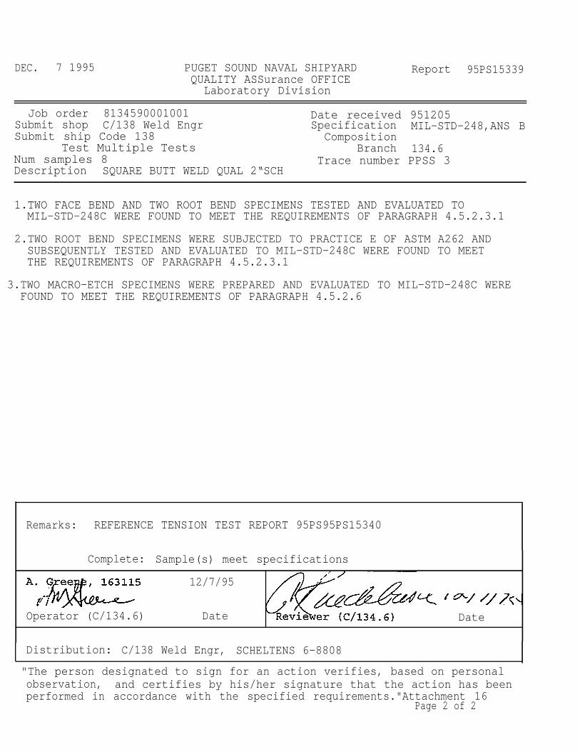
Job order 8134590001001 Date received 951205Submit shop C/138 Weld Engr Specification MIL-STD-248,ANS BSubmit ship Code 138 Composition
Test Multiple Tests Branch 134.6Num samples 8 Trace number PPSS 3Description SQUARE BUTT WELD QUAL 2“SCH
1.TWO FACE BEND AND TWO ROOT BEND SPECIMENS TESTED AND EVALUATED TOMIL-STD-248C WERE FOUND TO MEET THE REQUIREMENTS OF PARAGRAPH 4.5.2.3.1
2.TWO ROOT BEND SPECIMENS WERE SUBJECTED TO PRACTICE E OF ASTM A262 ANDSUBSEQUENTLY TESTED AND EVALUATED TO MIL-STD-248C WERE FOUND TO MEETTHE REQUIREMENTS OF PARAGRAPH 4.5.2.3.1
3.TWO MACRO-ETCH SPECIMENS WERE PREPARED AND EVALUATED TO MIL-STD-248C WEREFOUND TO MEET THE REQUIREMENTS OF PARAGRAPH 4.5.2.6
Remarks: REFERENCE TENSION TEST REPORT 95PS95PS15340
Complete: Sample(s) meet specifications
12/7/95
Operator (C/134.6) Date Date
Distribution: C/138 Weld Engr, SCHELTENS 6-8808
"The person designated to sign for an action verifies, based on personalobservation, and certifies by his/her signature that the action has beenperformed in accordance with the specified requirements."Attachment 16
Job order 9138040140000 Date received 960202Submit shop C/138 Weld Engr Specification MIL-STD-248CSubmit ship Code 138 Composition MONEL
Test Tensile, Lab Proc. 005 Branch 134.6Num samples 2 Trace number PPNC-2 & 3Description SQUARE BUTT WELDING PROD 2“
TWO PIPES (PPNc-2,PpNC-3) WERE TENSILE TESTED AS REQUESTED BY c/138.
HE PIPE SPECIFICATION IS MIL-T-1368. THE WELDMENT SPEC. IS MIL-E-21562,
N 60. THE RESULTS AREC AS FOLLOWS:
PPNC-2 PPNC-3 REQUIRED
BREAKING LOAD(lbs) 88,100 87,100 PIPE & WELD
TENSILE STRENGTH(psi) 84,000 81,000 70,000psi min
ELONGATION (%) 22 22 35 30
THE LOCATION OF THE FRACTURES IN BOTH OF THE SAMPLES WERE DIAGONAL ACROSS
HE WELD.
Remarks: AMENDMENT #1 DUE TO INCORRECT TRACE
Complete: FOR INFORMATION ONLY ------
Distribution: C/138 Weld Engr, SCHELTENS 6-8808
“The person designated to sign for an action verifies, based on personalobservation, and certifies by his/her signature that the action has beenperformed in accordance with the specified requirements. ” Attachment 17
Job order 9138040140000 Date received 960202Submit shop C/138 Weld Engr Specification MIL-STD-248Submit ship Code 138 Composition
Test Multiple Tests Branch 134.6Num samples 6 Trace number PPNC-1Description SQUARE BUTT WELD PROD BENDS
TWO MACRO SPECIMENS WERE PREPARED AND EVALUATED IN ACCORDANCE WITHMil-STD-248C AND WERE FOUND To MEET THE REQUIREMENTS OF PARAGRAPH 4.5.2.6.
TWO FACE AND TWO ROOT BEND SPECIMENS WERE TESTED AND EVALUATED INACCORDANCE WITH Mil-STD-248C AND WERE FOUND TO MEET THE REQUIREMENTS OFPARAGRAPH 4.5.2.3.1.
"The person designated to sign for an action verifies, based on personalobservation, and certifies .by his/her signature that the action has beenperformed in accordance with the specified requirements.” Attachment 17
Page 2 of 2
Attachment 18Page 1 of 2
SEAL* 1/16” DIA.** 50 TO 1200.191” TO 0.250” ROOT NONE 90 TO 150
COVER 1/16”, 3/32” 50 TO 110
* TACK WELD PIPE JOINT THEN SEAL WELD. BOTK TACK AND SEALWELDS ARE CONSUMED BY THE ROOT PASS.
1 TO 3 INCHES PER MINUTE
TRAVEL SPEED: SEAL -3 TO 6 INCHES PER MINUTEROOT- 0.5 TO 1.5 INCHES PER MINUTECOVER -1 TO 3 INCHES PER MINUTE
Attachment 18Page 2 of 2
GTAW OF STAINLESS STEEL (300 SERIES CRES)SQUARE BUTT PIPE JOINT USING PULSE PURGE
SQUARE BUTT (SEE FIGURE 1) 0.125” MAX. GAP
ALL POSITIONS
0.100” TO 0.250”
300 SERIES CRES (S-8)
1/16” and 3/32” DIA. OF ML-E-19933, SEESELECTION CHART
1/16” AND 3/32” DIA., 2% THORIATED90° BLUNT FOR SEAL AND ROOT PASS4/1 TAPER FOR COVER PASS, SEE FIGURE 2
1/2” m. EXTENSION WITH #7 CUP
95% ARGON AND 5% HYDROGEN/15 TO 20 CFH
ARGON (<1% OXYGEN CONTENT) / 8 TO 12 CFH
STRAIGHT, 0.0 TO 1.5 INCHES OF WATERPULSE, 0.0 TO 2.5 INCHES OF WATER
SAW CUT AND DEBURRED
STAINLESS STEEL WIRE BRUSHED AND EMERYCLOTHED 1“ FROM JOINT, ISOPROPYLALCOHOL CLEANED.
60”F MIN.
350”F MAX.
FORCED AIR COOLING
Attachment 19Page 1 of 2
ICOVER 1/16”, 3/32” 35 TO 80SEAL* 1/16” DIA.** 50 TO 100
0.191” TO 0.250” ROOT NONE 90 TO 130COVER 1/16”. 3/32” 40 TO 110
* TACK WELD PIPE JOINT THEN SEAL WELD. BOTH TACK AND SEALWELDS ARE CONSUMED BY THE ROOT PASS.
** FILLER MATERIAL IS USED ON SEAL IF GAP EXCEEDS O.O30", WIRE FEED
1 TO 3 INCHES PER MINUTE
TRAVEL SPEED: SEAL -3 TO 6 INCHES PER MINUTEROOT- 0.5 TO 1.5 INCHES PER MINUTECOVER -1 TO 3 INCHES PER MINUTE
#l LOW CARBON GRADES OF THESE FILLER MATERIALS MAYBE USEDWHEN REGULAR GRADE FILLER MATERIALS ARE NOT AVAILABLE AT THEWORK SITE ELECTRODE STORAGE / HOLDING AREA.
Attachment 19Page 2 of 2
GTAW OF NICKEL COPPER (Nicu)SQUARE BUTT PIPE JOINT USING PULSE PURGE
COOLING BETWEEN BEADS . . . . . . . . . FORCED AIR COOLING
Attachment 20Page 1 of 2
* TACK WELD PIPE JOINT THEN SEAL WELD. BOTH TACK AND SEALWELDS ARE CONSUMED BY THE ROOT PASS.
** FILLER MATERIAL IS USED ON SEAL IF GAP EXCEEDS 0.030”, WIRE FEED1 TO 3 INCHES PER MINUTE
TRAVEL SPEED: SEAL -3 TO 6 INCHES PER MINUTEROOT- 0.5 TO 1.5 INCHES PER MINUTECOVER -1 TO 3 INCHES PER MINUTE
Attachment 20Page 2 of 2
CARBON STEEL SQUARE BUTT AMI SETTINGS
SQUARE BUTT AMI SETTINGS
NOTES :
1. Unless otherwise noted, all welding will be done in the horizontal fixed position.
2 . Unless otherwise noted, travel direction will be counter clockwise
3. The travel speed was adjusted as welding progressed to compensate for the changingweld position. The varying travel speeds for each weld joint are documented on theirrespective figures below. If’ a primary amperage change was made, it was alsodocumented on the respective figure.
Attachment 21Page 1 of 1
STAINLESS STEEL SQUARE BUTT AMI SETTINGS
SQUARE BUTT AMI SETTINGS
NOTES :
1. Unless otherwise noted, all welding will be done in the horizontal fixed position.
2. Unless otherwise noted, travel direction will be counter clockwise.
3. The travel speed was adjusted as welding progressed to compensate for the changingweld position. The varying travel speeds for each weld joint are documented on theirrespective figures below. if a primary amperage change was made, it was alsodocumented on the respective figure.
Attachment 22.Page 1 of 1
t
3“ SCH 80Cres0.250
3“ SCHCres0.300
80
‘ : .
Attachment 23Page 1 of 1
TUNGSTEN TIP SHAPES
B L U N T T U N G S T E N
FIGURE 4
TYPICAL PULSE PURGE ARRANGEMENT
I
NOTES FOR “MANUALLY WELDED SQUARE BUTT TEST MATRIX”
1.
2.
3.
4.
5.
6.
7.
8.
9.
10,
Data in columns referencing this note relates to welds made with a Steady Arc(SA) constant current, Pulsing Purge (PP) and 95% Argon with 5% Hydrogenshielding gas (95/5). This column documents the weld amperage used (i.e. 52A)and the peak pulse pressure measured in “inches of water” (i.e. 1.2).
Data in columns referencing this note relates to welds made with a Steady Arc(SA) constant current, Steady Purge Flow (SP) and 95% Argon with 5%Hydrogen shielding gas [95/5). This column documents the weld amperage used(i.e. 56A) and the constant purge pressure used in “inches of water”.
Data in columns referencing this note relates to welds made with a Pulsing Arc(PA) pulsing current, Steady Purge Flow (SP) and 95% Argon with 5% Hydrogenshielding gas (95/5). This column documents the average weld amperage used (i.e.55A) and the Arc Pack 350 Pulse Control Program Number (i.e. 3). Programnumber 3 requires a peak amperage of 69 amps (peak time of .80 seconds andbackground time of .53 seconds) to average 55 amps.
This weld was made using a 1/16“ square ended tungsten.
These settings were used on a weld that passed X-Ray and destructive testing.
These settings were used on weld joints that had a 45° bevel and a 0.200” rootface. One used a flat insert and the other no insert.
Full penetration could not be achieved on this wall thickness.
This weld was made using a 1/16” 90° blunt tungsten.
Unless otherwise noted, all welds were made using a 3/32” 90° blunt tungsten.
All welding was done in the horizontal fixed position.
TABLE II
NOTES:
1,
2.
3.
4.
5.
Each space on the chart represents a test weld.
All Jt I & Jt 2 welds will be made on a saw cut square butt weld end prep, see Figure 9.Two consecutive welds will be made on this end prep to confirm repeatability of weldresults.
Jt 3 welds will be made on a saw cut square butt weld end prep with a 1/16” thick flatconsumable insert with a depth equal to or slightly greater than the wall thickness of the testpipe, see Figure 9.
Data entries in each space will document welding results. Acceptable tests will liamperage (primary amps and background amps [i.e. 155/45] ) and the travel speeds in per minute (slowest to the fastest [i.e. 5.3 -6] ) that were used.
All welding will be done in the horizontal fixed position, unless otherwise noted.
Additional copies of this report can be obtained from theNational Shipbuilding Research and Documentation Center:
http://www.nsnet.com/docctr/
Documentation CenterThe University of MichiganTransportation Research InstituteMarine Systems Division2901 Baxter RoadAnn Arbor, MI 48109-2150