72
The new Alien Pod Digital Video Recorder Operations Manual Model DSD106 Version 3.0 4 Channel Real Time DVR Networkable Mobile Phone Monitoring Intelligent Security and Fire Ltd

The new Alien Pod Digital Video Recorder
Operations Manual
Model DSD106
Version 3.0
4 Channel Real Time DVR Networkable Mobile Phone Monitoring
Inte
lligen
t Sec
urity
and
Fire
Ltd

2
Table of Contents PageWelcome 4Important Safeguards and Warnings 41. Features 5 Local functions 52. Installation 6 2.1 Checking the DVR and its Accessories 6 2.2 HDD Installation 6 2.3 Rear Panel Description 7 2.3.1 DSD106 7 2.3.2 External Alarm In/Out & RS485 connections 83. Operational Instructions 9 3.1 Front Panel 9 3.2 IR Controller 11 3.3 Menu Description 13
3.3.1 Menu Items 133.3.2 Menu Operation 14
4. Basic Operation Guide 15 4.1 Username and Password 15 4.2 PTZ Control 17 4.3 Manual Record 19 4.4 Playback 20 4.5 Backup Recorded Files 22 4.6 Shutdown DVR 245. Parameter Setup Guide 25 5.1 Administrator and Password 25 5.2 Add and Delete User 26 5.3 Device ID 29 5.4 Video Output Standard 30 5.5 OSD Setup 30 5.6 Camera Input Adjustment – Camera Settings 32 5.7 Camera Input Adjustment – Mask Area Setup 32 5.8 View Tampering Alarm 33 5.9 Video Loss Alarm 34 5.10 Motion Detection Alarm 35 5.11 Preview Properties 37 5.12 Recording Setup 38 5.13 External Alarm Input and Relay Output 40
Inte
lligen
t Sec
urity
and
Fire
Ltd

3
5.14 Network Parameters 455.15 PTZ 47
6. Utilities 506.1 Default Parameters 506.2 Firmware 516.3 Hard Disk 526.4 Alarm Out 536.5 Reboot 536.6 Power Off 536.7 View Log 536.8 System Information 55
7. Firmware Upgrade 567.1 FTP Server Setup 567.2 Upgrade Mode 58
8. Web HTTP Operation 598.1 Network Connection 59
8.1.1 Login and Logout 599. Networking a Digital Video Recorder 60
9.1 Configure the DVR to operate with a modem router 609.2 For Beginners 61
9.2.1 How do I set my PC to obtain an IP address automatically? 62
9.2.2 How do I set my PC’s IP address Manually? 629.2.3 How do I find out my PC’s IP address? 629.2.4 How do I use Ping to test a Connection to my DVR? 629.2.5 How do I configure a Router for Remote Access? 639.2.6 How do I find the On-Line Support? 63
9.3 Option 1: Connect a DVR directly to a single PC 649.4 Option 2: Connect a DVR to a switch or hub 659.5 Option 3: Connecting for Internet Access 669.6 Network Cable Connections 67
Appendix A Hard Disk Capacity Information 68Appendix B Recording Timetable 69Appendix C Quick Help Guide 70Appendix D Specifications 72
Inte
lligen
t Sec
urity
and
Fire
Ltd

4
WelcomeThis operating manual is designed to be a reference tool for the installation andoperation of your system.Here you can find information about this series DVR features and functions, as wellas a detailed menu tree.Before installation and operation please read the following safeguards and warningscarefully!
Important Safeguards and Warnings1 Electrical SafetyThe installation and operation should conform to local electrical safety codes.
2 Transportation SecurityAvoid placing equipment on top of this DVR and do not subject the unit to strongvibration or water during transportation, storage and installation.
3 InstallationAlways install the unit in an upright position. Handle with due care.Do not apply power to the DVR before completing the installation.Do not place objects on the DVR or restrict air flow to this DVR.
4 Qualified Engineers NeededOnly entrust examination and repair work by qualified service engineers.We are not liable for any problems caused by unauthorised modifications or attemptedrepair.
5 EnvironmentThe DVR should be installed in a cool, dry place away from direct sunlight,inflammable, explosive substances etc.
Note: Note that the manufacturer of this product reserves the right to makemodifications to the DVR and/or these instructions without prior notice.
Inte
lligen
t Sec
urity
and
Fire
Ltd
5
1 Features
This DVR range uses the embedded MCU and realtime operating systemcombining the most advanced technology in the information industry. It incorporatesvideo and audio encoding and decoding, hard disk record and TCP/IP. The firmwareis installed in the flash drive and is very stable and reliable.The DVR has both the features of a digital video recorder and a digital videoserver. It works as a standalone unit or can be incorporated into a powerful surveillancenetwork, suitable for use in shops, transportation, warehouses, clubs and public houses etc.,and particularly where space is limited.CompressionSupports CIF mode at 25FPS, 2CIF at 12FPS and 4CIF at 6FPS, multi area motiondetection, OSD and changeable OSD position, LOGO and changeable LOGO position.
Local functionsRecordSupports multiple record type, including realtime, manual record, motion detection,external alarm, motion&alarm, motion/alarm. Allows selection of CIF mode at 25FPS,2CIF at 12FPS and 4CIF at 6FPS.Supports 1 SATA Hard Drive, FAT32 file system, HDD SMART technology, cycleor non cycle record, backup of recorded files and clips.Supports USB memory, USB HDD, USB CD-R/W and USB DVD-R/W.Preview and PlaybackSupports internal composite monitor or VGA output and composite spot monitor. Internalor VGA monitor provides multiple preview modes, sensitive area mask, camera alarmblock, single channel playback by file or time and displays local record status. Spotprovides single channel preview mode only.PTZSupports numerous PTZ protocols, presets, sequence and cruise.AlarmsSupports exception alarm, motion detection alarm, external alarm etc.OthersSupports IR control and multi-level user management.NetworkSupports TCP, UDP, RTP, Multicast for network preview and PPPoE for broadband.Supports remote parameter setup, can send alarm information to remote centre,network control PTZ, network record live stream, network download and play backrecorded files in DVR and remotely upgrade firmware.
Inte
lligen
t Sec
urity
and
Fire
Ltd

6
2. Installation
2.1 Checking the DVR and its AccessoriesWhen you receive the product, check that all the items are included in your package.
2.2 HDD InstallationThe DVR is not fitted with a Hard Drive unless purchased separately. The size ofthe Hard Drive can be calculated according to the total capacity required. A table issupplied at the end of this manual..This DVR uses one SATA Hard Drive up to a maximum of 1 Tb.
First remove DVR case top.
Fit hard drive to base plate with screws.
Connect SATA data cable correctly and then power cable. Ensure cables are fittedtightly.
Refit DVR case top and power up unit.
Ensure HDD is formatted before use. Details can be found in this manual.
Inte
lligen
t Sec
urity
and
Fire
Ltd
7
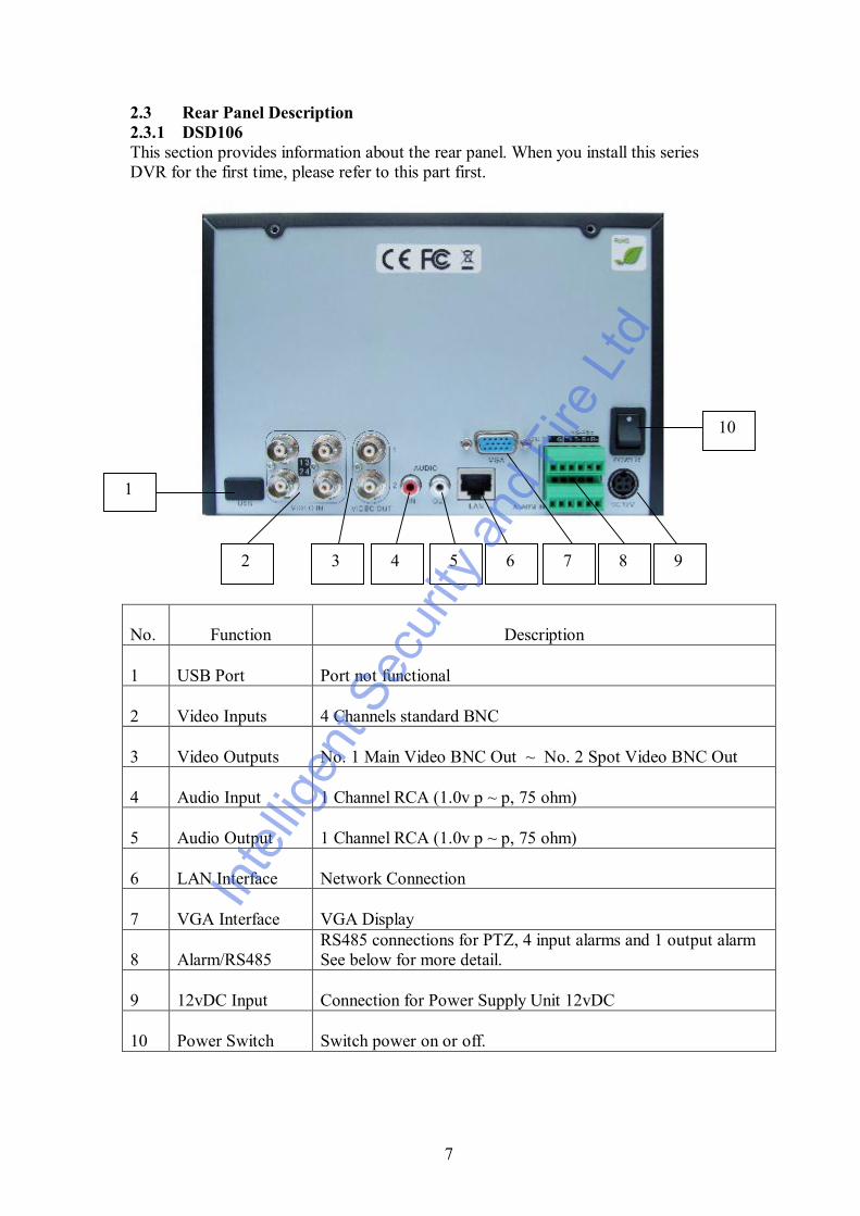
2.3 Rear Panel Description2.3.1 DSD106This section provides information about the rear panel. When you install this seriesDVR for the first time, please refer to this part first.
No. Function Description
1 USB Port Port not functional
2 Video Inputs 4 Channels standard BNC
3 Video Outputs No. 1 Main Video BNC Out ~ No. 2 Spot Video BNC Out
4 Audio Input 1 Channel RCA (1.0v p ~ p, 75 ohm)
5 Audio Output 1 Channel RCA (1.0v p ~ p, 75 ohm)
6 LAN Interface Network Connection
7 VGA Interface VGA Display
8 Alarm/RS485RS485 connections for PTZ, 4 input alarms and 1 output alarmSee below for more detail.
9 12vDC Input Connection for Power Supply Unit 12vDC
10 Power Switch Switch power on or off.
1
2 3 4 5 6 7 8 9
10
Inte
lligen
t Sec
urity
and
Fire
Ltd
8
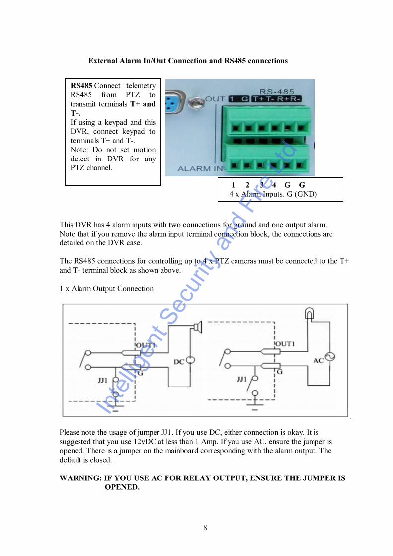
External Alarm In/Out Connection and RS485 connections
This DVR has 4 alarm inputs with two connections for ground and one output alarm.Note that if you remove the alarm input terminal connection block, the connections aredetailed on the DVR case.
The RS485 connections for controlling up to 4 x PTZ cameras must be connected to the T+and T- terminal block as shown above.
1 x Alarm Output Connection
Please note the usage of jumper JJ1. If you use DC, either connection is okay. It issuggested that you use 12vDC at less than 1 Amp. If you use AC, ensure the jumper isopened. There is a jumper on the mainboard corresponding with the alarm output. Thedefault is closed.
WARNING: IF YOU USE AC FOR RELAY OUTPUT, ENSURE THE JUMPER IS OPENED.
1 2 3 4 G G 4 x Alarm Inputs. G (GND)
RS485 Connect telemetryRS485 from PTZ totransmit terminals T+ andT-.If using a keypad and thisDVR, connect keypad toterminals T+ and T-.Note: Do not set motiondetect in DVR for anyPTZ channel.
Inte
lligen
t Sec
urity
and
Fire
Ltd
9
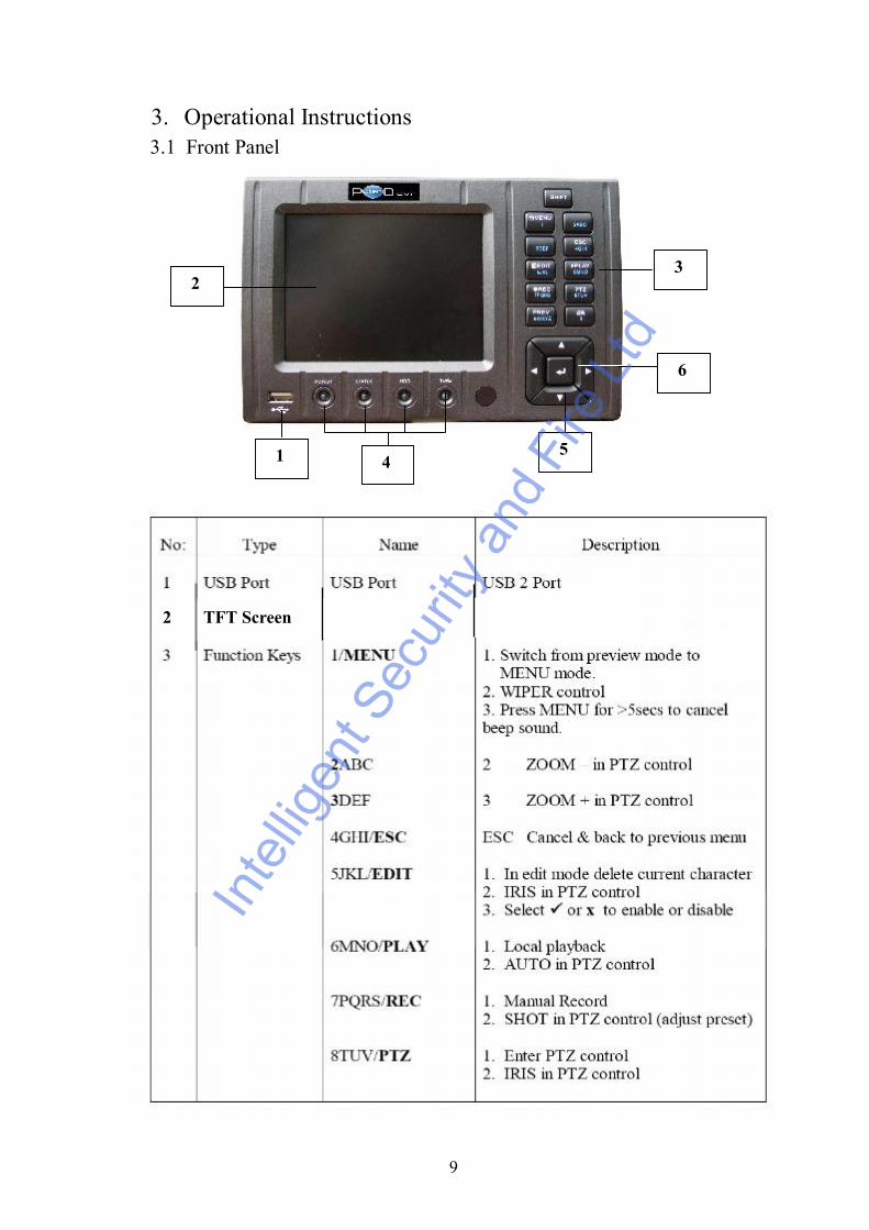
3. Operational Instructions
2 TFT Screen
1 45
32
6
3.1 Front Panel
Inte
lligen
t Sec
urity
and
Fire
Ltd

10
NOTE: SHIFT button is used to switch between numeric keys and function keys
6
POWER
HDDTxRx
Inte
lligen
t Sec
urity
and
Fire
Ltd

11
Inte
lligen
t Sec
urity
and
Fire
Ltd

12
Loading the batteries in IR Controller1. Remove battery cover.2. Insert battery ensuring polarity correct.3. Replace battery cover.
Start the IR ControllerAim the IR Controller at the front of the DVR standing a few feet from the unit.Press DEV key and input the DVR I.D (default is 255 but can be changed in theDisplay Menu and then press ENTER key. Check that the IR Status light is displayingGreen). Note that in some models the DVR I.D default may be set to 88.
Stop the IR ControllerWhen the IR status is on, press the DEV key again to turn off the IR Controller. Thestatus lamp will now switch off and the IR Controller will not operate the DVR.
Switching the DVR offWhen the IR Controller status is on, press the POWER key for several seconds andthe DVR will power off.
Troubleshooting the IR ControllerIf the IR Controller does not operate the DVR then check the following items:
1. Check battery connections
2. Check battery charge
3. Check there is nothing covering the DVR IR sensor.
4. Check I.D in Display menu to see what has been set as default. Use this I.D to setup IR Controller or change the value in the Display menu and use that by pressing DEV key, entering I.D and pressing the ENTER key on the IR Controller.
5. Check that the IR Status light on the front of the DVR is displaying Green.
Inte
lligen
t Sec
urity
and
Fire
Ltd

13
Inte
lligen
t Sec
urity
and
Fire
Ltd

14
3.3.2 Menu Operation
How to enter menu mode
Press MENU key to enter DVR Main menu
Press PLAY key to enter Playback menu
Press REC key to enter Manual Record menu
Press PTZ key to enter PTZ control interface.
Special Note: You must input username and password. The default username isadmin and the password is 12345.
Main Menu Description
The small rectangular frame allows the user to move to the required menu option. Tomove, use the or keys on the Control Key Direction Unit (CKDU).When you have selected the required icon press Enter (this is the center key on theCKDU).
Inte
lligen
t Sec
urity
and
Fire
Ltd
15
4. Basic Operation Guide
4.1 Username and Password
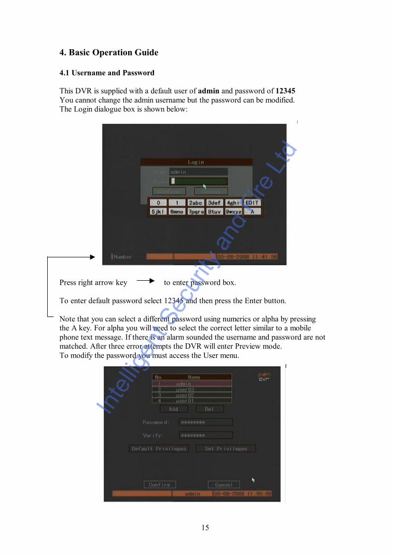
This DVR is supplied with a default user of admin and password of 12345You cannot change the admin username but the password can be modified.The Login dialogue box is shown below:
Press right arrow key to enter password box.
To enter default password select 12345 and then press the Enter button.
Note that you can select a different password using numerics or alpha by pressingthe A key. For alpha you will need to select the correct letter similar to a mobilephone text message. If there is an alarm sounded the username and password are notmatched. After three error attempts the DVR will enter Preview mode.To modify the password you must access the User menu.
Inte
lligen
t Sec
urity
and
Fire
Ltd

16
To add a new user and password press the Add button and enter username. Now enterthe Password and verify by re-entering password.
SPECIAL NOTE: Please refer to section 5 regarding the setting of access rights. Ifthese rights are not set then new users will not be able to operate this DVR.
Inte
lligen
t Sec
urity
and
Fire
Ltd

17
4.2 PTZ ControlIn preview mode press PTZ key and in login mode select username and password.You can now enter the PTZ control interface. Note that the user must have the PTZcontrol rights set.
In menu mode press the PTZ menu..
There is a PTZ Control prompt in the PTZ control interface. The displayed cameraname details the name of the camera you are controlling.
Select ChannelIn PTZ control mode you can press the numeric keys to select a channel. If DVR hasless than 10 channels, press one numeric key to select. For example to select camera2 press the 2 key. If the DVR has 10 or more channels you must press two numerickeys to select channel number. For example for camera 2 you must select keys 0 and2 simultaneously and for camera 12, select numeric keys 1 and 2.
PTZ Control KeysDirection keysZoom keys ZOOM+ ZOOM-Focus keys FOCUS+ FOCUS-Iris keys IRIS+ IRIS-Adjust Preset keys REC/SHOTAuto Control key PLAY/AUTOWiper Control key WIPER/MENULight Control key LIGHT/F1Auxiliary Control AUX/F2
Inte
lligen
t Sec
urity
and
Fire
Ltd

18
Adjust Preset NumberIn PTZ control mode, press the REC/SHOT key, and then press the preset number(three numeric keys) and the relevant preset can be selected. Press REC/SHOT keyagain and change the preset number. When you exit PTZ control mode, the camerawill stay at the current position.
Note: The PTZ preset number is set already. Please refer to PTZ menu for preset setupinstructions. Firmware version 1.4 upwards can support up to 28 presets.
Start/Stop auto in PTZ control modeIn PTZ control mode press PLAY/AUTO key to start PTZ auto function. PressPLAY/AUTO key again to stop. When PTZ is in auto mode and you exit this modethe PTZ will continue to auto function. You must enter the PTZ control mode againand press the PLAY/AUTO key to stop.
Exit PTZ control modePress ESC or ENTER to exit and return to preview mode.
Inte
lligen
t Sec
urity
and
Fire
Ltd

19
4.3 Manual Record
The user must have the corresponding rights to use this facility. In preview modepress the REC key and enter the username and password to enter the Manual Recordinterface. In menu mode press the REC key to enter Manual Record directly.
Channel: Lists the channel numbers available on this DVR
Status: Channel status has four modesX = idleGreen = channel recording (schedule, motion or alarm)Red = network transmissionOrange = recording and network transmission
Start/Stop ü = start corresponding channel recordingX = stop corresponding channel recording
Start All Press this button to start all channels recording
Stop All Press this button to stop all channels recording
Exit Manual RecordPress ESC key to enter preview mode. Press MENU key to enter main menu.Press PLAY to enter playback menu. Press PTZ key to enter PTZ control mode.
Inte
lligen
t Sec
urity
and
Fire
Ltd

20
4.4 Playback
The user must have playback rights. In preview mode press the PLAY key, selectusername and password to enter playback interface. In menu mode press the PLAYkey and enter playback interface directly.
Note that this DVR only supports one channel playback.
Chan: Use or keys to select one channel.
Rec. Type: Use or keys to select recorded files. There are 5 file types thatcan be selected: All = All files
All Time = All schedule recordingsMotion Detect = Motion detection filesAlarm = Alarm recorded filesManual = Manually recorded files
Time: Enter the “ From and To” date and time selected
Search: Search the matched recorded files and display them in list box. If nofiles are found a corresponding dialogue box is displayed.
Play by Time:Playback the recorded channel based on time section.
Select Page: In the file list box, only 8 files are displayed per page. If the selectioncovers more than 8 files these can be seen by selecting further pages. Up to 500 pagescontaining a maximum of 4000 files can be searched at one time. Use the numerickeys or the up and down arrow buttons to selected the required page.
File List Box: This lists the matched files. File start time and file size are displayed.Use the up and down arrow keys to move the scroll bar to select file.
Inte
lligen
t Sec
urity
and
Fire
Ltd

21
Backup Devices: You can select USB memory stick, USB HDD or USB CD-R/Wto backup files.
Copy: Starts backupBackup Today: Backup all recorded files from today.
There are two kinds of playback mode. Search and playback file, and playback bytime.
Search and playback file: In the playback interface you can select only onechannel playback but using the client software you can playback up to 4 channels.
Select channel, record type and time from and to. Now click on Search and the filesfound for that period will be listed in the matched files list. If you click on one fileand then press the PLAY key the recorded file will play back. If the DVR cannot findmatched files a failure dialogue will be displayed.
1. Adjust play progress backwards or forwards2. Adjust play speed. Normal = 1x. Decrease to 1/2x, 1/4x, 1/8x and single frame. Increase to 2x, 4x, 8x and MAX.3. Pause/continue. If setting single frame press Enter to display each frame.4. Audio5. Copy segment. Press EDIT to start copy.6. Go backwards.7. Select enlarged segment for viewing.8. Press the ESC button to return to preview mode.NOTE: When DVR is busy and you select high speed playback you may findactual speed can be reduced.
Inte
lligen
t Sec
urity
and
Fire
Ltd
22
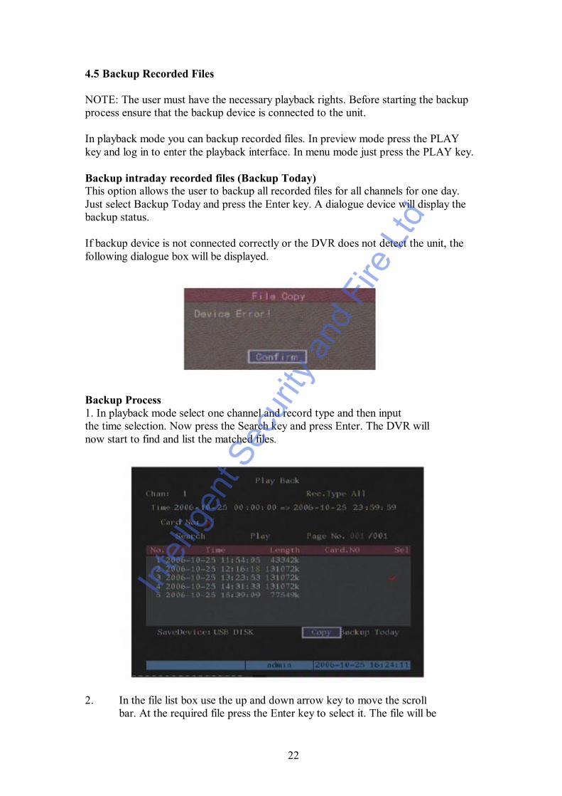
4.5 Backup Recorded Files
NOTE: The user must have the necessary playback rights. Before starting the backupprocess ensure that the backup device is connected to the unit.
In playback mode you can backup recorded files. In preview mode press the PLAYkey and log in to enter the playback interface. In menu mode just press the PLAY key.
Backup intraday recorded files (Backup Today)This option allows the user to backup all recorded files for all channels for one day.Just select Backup Today and press the Enter key. A dialogue device will display thebackup status.
If backup device is not connected correctly or the DVR does not detect the unit, thefollowing dialogue box will be displayed.
Backup Process1. In playback mode select one channel and record type and then inputthe time selection. Now press the Search key and press Enter. The DVR willnow start to find and list the matched files.
2. In the file list box use the up and down arrow key to move the scrollbar. At the required file press the Enter key to select it. The file will be
Inte
lligen
t Sec
urity
and
Fire
Ltd

23
ticked. You can use the same method to select other files to backup.When you have selected the files to backup go to the next step.
3. At this point select the required backup device. You can select fromthe following devices: USB memory stick or USB CD-R/W.
4. Press the Save button and press the Enter key to start backup. Whenbackup starts the corresponding message box will indicate the result.
Backup video segmentAn additional facility is available to backup parts of an incident. This maybe useful when there is a part of the recording not required. The following steps needto be followed:
1. Start playback or select playback by time.
2. Press the Edit key to start selecting the current playback image and press Edit again to stop selecting the segment required.
3. Repeat step 2 to select up to 30 segments maximum.
4. On completion of the selection of segments press the ESC key and a dialogue box will be displayed. If you press the Confirm key the DVR will start to backup the selected segments. If you press the Cancel button the DVR will abort the backup.
Inte
lligen
t Sec
urity
and
Fire
Ltd

24
4.6 Shutdown DVR
NOTE: Do not power off the unit by removing the mains supply as this may damagethe Hard Drive fitted. Always use the Power Off facility in the Utilities menu or pressthe Power key on the front panel or on the I.R Controller.
Shutdown DVR normally
Using the MenuEnter the Utilities menu and press Power Off button. Now enter dialogue box andpress Confirm to shutdown DVR.
Using the Power key on front of DVR or via the IR ControllerPress the Power button for 3 seconds. In preview mode a login dialogue box will bedisplayed. Enter password and press Enter to display power off dialogue box. Nowpress confirm to shutdown DVR. If you enter incorrect password three times the DVRwill return to preview mode.
In menu mode if the user has the Utilities rights, you can enter into power offdialogue and press confirm to shutdown DVR. Otherwise the user cannot shutdownthe DVR. If the DVR is shutdown correctly the power light is illuminated red.
NOTE: When the Shutdown message appears, please do not press the Power keyagain else the DVR will not shut down.
Shutdown DVR abnormallyIf you power down the unit without going through the menu or via the Power key onthe machine, there is a chance that the hard drive could be damaged. When power islost through a power failure then this can happen so it is suggested that the unit isconnected to a UPS unit.In
tellig
ent S
ecur
ity a
nd F
ire L
td

25
5. Parameter Setup Guide
NOTE: Only users with Parameters Setup rights can access these menus. When thefollowing parameters are modified and saved you must reboot the DVR to make thenew parameters effective. Some parameters do not need a reboot. The following do:-
· Network parameters· Stream type, resolution and record schedule· External alarm sensor· View tampering alarm schedule· Video loss alarm schedule· Motion Detection alarm schedule· External alarm schedule· Alarm output schedule· Transaction· Change video output standard
5.1 Administrator and PasswordWhen the DVR leaves the factory there is one default administrator.The username is admin and the password is 12345
Password ModificationPress the Menu key and login selecting the username admin. Use the right arrow keyand move cursor to password edit box. Input 12345 and press confirm to enter theadministrator menu.
Select the User menu and press Enter key to enter the User Management menu.
In the username list box you can see only admin exists. Use the right arrow key tomove to the password edit box and press EDIT to enter edit status. Press numeric keysto input new password. The password must be a maximum of 16 numerals. Afterentering password press Enter to exit. Click on Verify and enter password again. Nowpress the Confirm button and press Enter. If password and verify password are the
Inte
lligen
t Sec
urity
and
Fire
Ltd
26
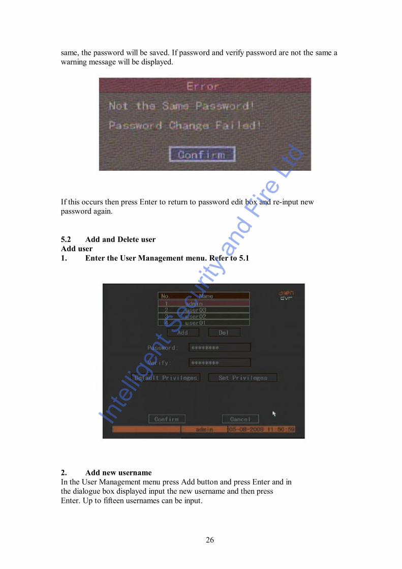
same, the password will be saved. If password and verify password are not the same awarning message will be displayed.
If this occurs then press Enter to return to password edit box and re-input newpassword again.
5.2 Add and Delete userAdd user1. Enter the User Management menu. Refer to 5.1
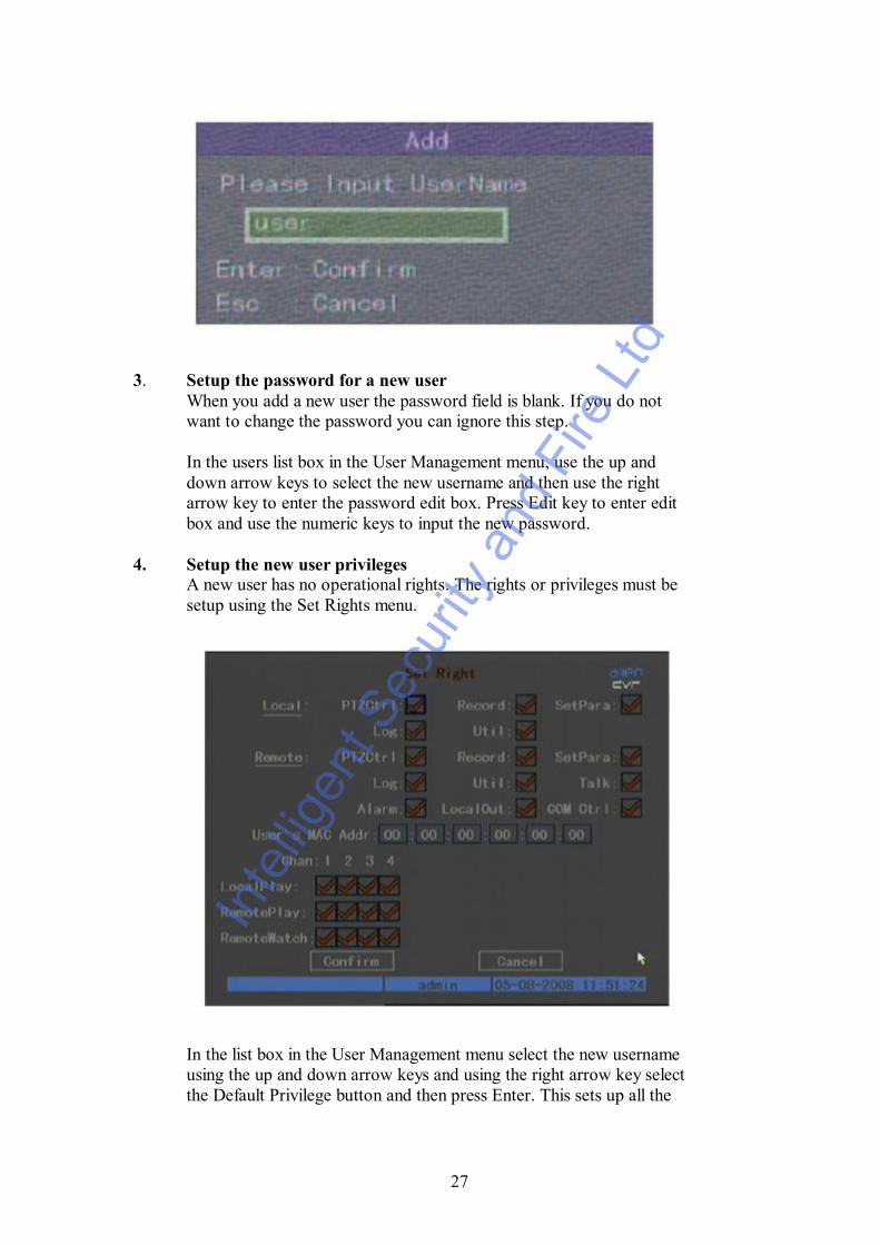
2. Add new usernameIn the User Management menu press Add button and press Enter and inthe dialogue box displayed input the new username and then pressEnter. Up to fifteen usernames can be input.
Inte
lligen
t Sec
urity
and
Fire
Ltd
27
3. Setup the password for a new userWhen you add a new user the password field is blank. If you do notwant to change the password you can ignore this step.
In the users list box in the User Management menu, use the up anddown arrow keys to select the new username and then use the rightarrow key to enter the password edit box. Press Edit key to enter editbox and use the numeric keys to input the new password.
4. Setup the new user privilegesA new user has no operational rights. The rights or privileges must besetup using the Set Rights menu.
In the list box in the User Management menu select the new usernameusing the up and down arrow keys and using the right arrow key selectthe Default Privilege button and then press Enter. This sets up all the
Inte
lligen
t Sec
urity
and
Fire
Ltd

28
rights appertaining to this username. These include local playback,remote playback and log access etc. If you wish to reduce these rightsselect the Set Privileges button. Use the left and right arrow keys tomove to the appropriate rights, then press Enter or Edit key to enable ordisable the facility. A tick confirms the right is enabled. On completionof changes press the Enter button to save the new user rights and returnto the User Management menu. If you press the Cancel button the userrights will be aborted.
5. Saving the new username password and rightsIn the User Management menu press the Confirm button and the userpassword and rights will be saved and you will be returned to the Mainmenu. If you press Cancel the user password and rights will be aborted.
User Rights DescriptionLocal RightsLocal rights are for local operators such as using the DVR front panel, IRremote and RS485 keyboard.PTZ Control: Local control of PTZRecord: Manual stop/start recordingPlayback: Local playback and backup of recorded filesParameter Setup: Local setup of DVR parametersLog: Locally view the DVR logUtilities: Locally upgrade firmware, format HDD, reboot DVR
and shutdown DVR etc.
Remote RightsPTZ Control: Remote control of PTZRecord: Remote manual start/stop recordingPlayback: Remote playback, download the recorded DVR filesParameters Setup: Remotely setup DVR parametersLog: Remotely view the DVR logUtilities: Remotely upgrade firmware, format HDD, reboot DVR
and shutdown DVRVoice: Client talks through DVRPreview: Network live previewAlarm: Remote control DVR alarm outputLocal Video Out: Remotely control DVR video output
MAC addressThe MAC address is not the address of the DVR but the PC that accesses theDVR. If you setup this MAC address only the PC with this MAC address canaccess this DVR.
Local PlayAdministrator can set local playback rights option for each channel.
Remote PlayAdministrator can set remote playback rights option for each channel.
Inte
lligen
t Sec
urity
and
Fire
Ltd

29
Remote WatchAdministrator can set remote preview rights for each channel.
Delete UserIn the User Management menu you can use the up and down arrows to selectone user, then use the right arrow key to select the DEL button. If you thenpress the Enter button a confirmation dialogue box is displayed and pressingthe Confirm button deletes the selected user. Pressing Cancel or ESC willabort the delete.
5.3 Device IDSelect the display menu:
When you use the IR controller to operate the DVR you must use the deviceID to select the DVR. The default device ID is 255. If you are using more thanone of these DVRs then ensure each unit is allocated a different ID. In Displaymenu move to the Device ID box and enter a device range 01 ~ 255. Press theConfirm button to save or press Cancel to abort. Whatever ID you set, you willneed to enter this on your remote controller. Aim the remote at the DVR andpress the DEV key, enter the ID set in the Display menu and then press Enteron the remote. The status led on the front of the DVR must turn to green.
Inte
lligen
t Sec
urity
and
Fire
Ltd

30
5.4 Video Output Standard and VGA Setup
Video Output StandardThis DVR will support PAL or NTSC video output. Set the video output tomatch the video input standard by selecting the Video Standard box with theup and down arrow keys and selecting PAL or NTSC. PAL is the standardused in the U.K.
VGA setupThere is one VGA interface on the rear of the DVR. Set the VGA resolution ofthe monitor in the Display menu. Select from the following options:1024 x 768 60Hz, 800 x 600 60Hz, 800 x 600 75Hz..Use the up and down arrow buttons to select option and then press Confirmbutton to save or press the Cancel button to abort.
5.5 OSD SetupOSD (On Screen Display) allows the system time and camera name to bedisplayed. OSD settings include: system time, time format, time displayposition, camera name, camera name display position etc.
System TimeIn the Display menu you can setup the DVR system date and time.
Display System TimeYou can also display the properties of each camera including display status,position and format. You can copy the properties from one camera to another.In the Image Setup menu select one camera:
Date OSDThere are four display modes: Opaque&Steady, Transparent&Steady,Transparent&Flashing and Opaque&Flashing. Move to Date OSD and selectone mode.
Inte
lligen
t Sec
urity
and
Fire
Ltd

31
Display Position and formatMove to the Position button and press Enter to enter setup image. Here youwill find there are 22 x 18 small panes with the OSD position marked in red.Use the arrow keys to move to the required OSD position.
Press Edit key to select OSD formatThe following OSD formats are provided:MM DD YYYY W hh:mm:ss (default)MM DD YYYY hh:mm:ssDD MM YYYY hh:mm:ssYYYY MM DD W hh:mm:ssYYYY MM DD hh:mm:ssYYYY = Year, MM = month, W = weekday, hh = hour, mm = minutes,ss = secondsPress Enter to save and return to Image menu or press ESC to abort.
Copy parametersAfter the setup properties of one camera has been completed you can copy thesame values to other cameras. Press the Copy to Camera box and enter therequired camera number.
Camera NameIn the Image menu you can set the name for each camera. Note that cameranames cannot be copied. The following steps cover setting the camera name:1. Select one camera2. Move to Name box and press Edit button and then input digital
numbers, uppercase or lowercase characters as detailed earlier.The camera name can be 32 characters long maximum.
3. Press Edit key to exit edit status. Select Confirm and press Enter tosave the change and you will now see the new camera name. PressCancel button or ESC key to abort.
NOTE: To change to Upper case, lower case, numerics or symbol press the Abutton and then press 0 to scroll through characters required. Click on thenumber appertaining to the character or symbol required.
Setup Camera Name PositionIf you do not want to display camera name disable the check box besidecamera Name with an X. If you enable the check box you can setup thecamera name position. The steps are:
1. Enter the Image Setup menu2. Select one camera3. Enable the check box on the side of the camera name and move to the
Position button. Now press Enter and using the arrow keys movecamera name position. When set, press Enter to fix position and returnto Image menu. Then press Confirm button to save. If Cancel or ESCis pressed in the Image Setup menu the change will be cancelled.
Inte
lligen
t Sec
urity
and
Fire
Ltd
32
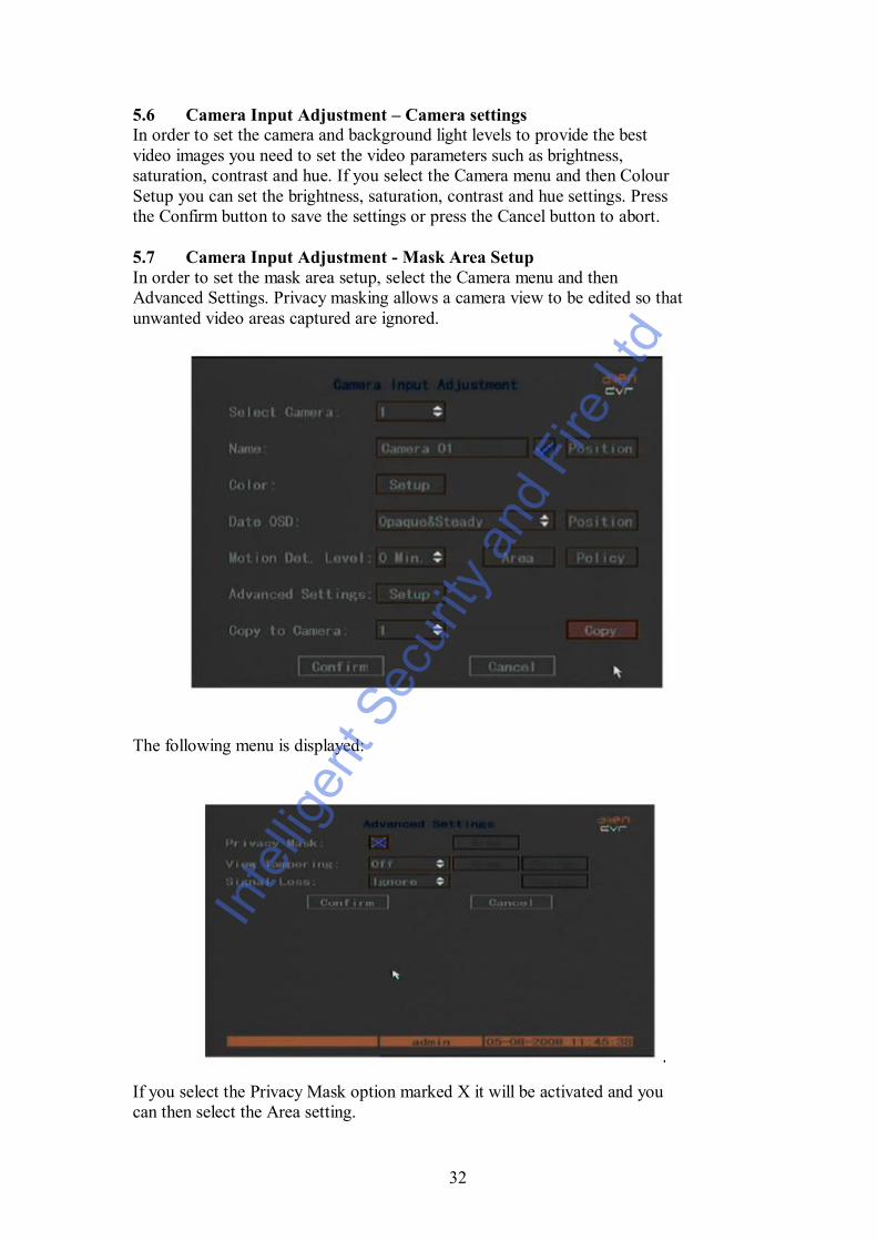
5.6 Camera Input Adjustment – Camera settingsIn order to set the camera and background light levels to provide the bestvideo images you need to set the video parameters such as brightness,saturation, contrast and hue. If you select the Camera menu and then ColourSetup you can set the brightness, saturation, contrast and hue settings. Pressthe Confirm button to save the settings or press the Cancel button to abort.
5.7 Camera Input Adjustment - Mask Area SetupIn order to set the mask area setup, select the Camera menu and thenAdvanced Settings. Privacy masking allows a camera view to be edited so thatunwanted video areas captured are ignored.
The following menu is displayed:
If you select the Privacy Mask option marked X it will be activated and youcan then select the Area setting.
Inte
lligen
t Sec
urity
and
Fire
Ltd

33
The following screen is displayed:
Move the yellow square using the mouse to where you wish to exclude videocapture. Now press the left mouse key and Edit button and use the arrow keysto set the first area. Press Edit again to save the mask area. The maximummask area is 8 x 8 panes and the minimum size is one pane. Press Enter toreturn to Advanced Settings and press Confirm to save the masks set. Press Ato clear all mask areas. The maximum mask areas are 4. The total mask areasare displayed during setup.
5.8 View Tampering AlarmThis option is used to produce an alarm warning if the camera video is blocked.Select Camera menu and Advanced settings and then select View Tamperingby clicking on up or down arrow buttons to the right of this. This will changethe Off display to either Low, Normal or High sensitivity and setup the Areaand Policy Boxes. The Area allows one box to be set similar to the PrivacyMasking option. Press Enter to return to the Advanced Settings box and thenclick on Confirm. If you click on the Policy button you can enter the ViewTampering Handle menu.
This allows the user to set up to four periods per day for one week The DVRwill react only as per schedule set. You can copy one days settings as anotherday. Do not overlap time periods and reboot DVR to make effective.
Inte
lligen
t Sec
urity
and
Fire
Ltd
34
Setup Alarm PolicyThe DVR will react to the Policy set. You can select one or more options fromthe following: On Screen Warning, Audible warning, Upload to Center andTrigger Alarm Output. Use the mouse to change the cross to a tick. Ensure theConfirm button is pressed to save the settings. Pressing ESC will abort thesetting. Any changes made to the parameters must be followed by a reboot.
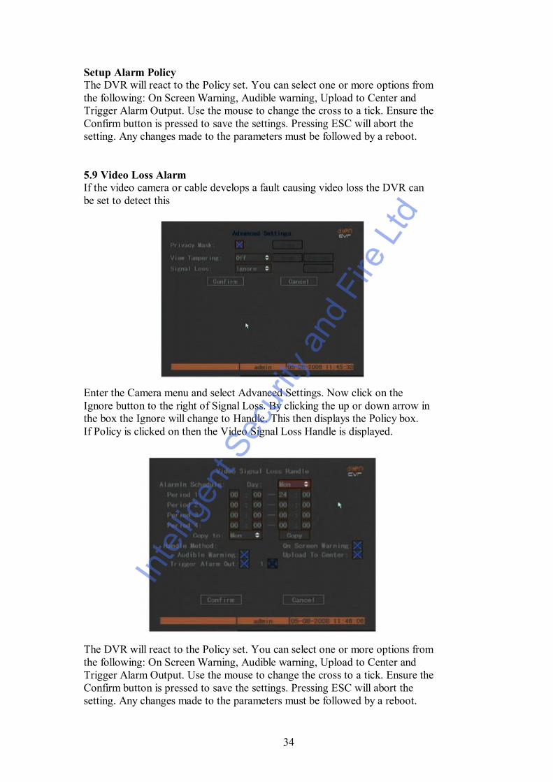
5.9 Video Loss AlarmIf the video camera or cable develops a fault causing video loss the DVR canbe set to detect this
Enter the Camera menu and select Advanced Settings. Now click on theIgnore button to the right of Signal Loss. By clicking the up or down arrow inthe box the Ignore will change to Handle. This then displays the Policy box.If Policy is clicked on then the Video Signal Loss Handle is displayed.
The DVR will react to the Policy set. You can select one or more options fromthe following: On Screen Warning, Audible warning, Upload to Center andTrigger Alarm Output. Use the mouse to change the cross to a tick. Ensure theConfirm button is pressed to save the settings. Pressing ESC will abort thesetting. Any changes made to the parameters must be followed by a reboot.
Inte
lligen
t Sec
urity
and
Fire
Ltd

35
5.10 Motion Detection AlarmThis function provides an alarm when motion detection is triggered.
Select the Camera menu and the above menu is displayed. Select Motion Det.Level which is the motion detect sensitivity. There are seven options. 0 is thelowest to 5 the highest and Off. If you leave option set to Off there will be noDVR response. If you select 0 ~ 5 this will activate Motion Area Setup andPolicy Setup. If you select 0 for low sensitivity the DVR will only respond tomajor motion changes. If you set sensitivity to high at the 5 end, only smallmotion changes will set off the motion detection.
Motion Area SetupYou must define the motion areas so the DVR can respond when there ismotion in the area set. In the above menu click on Motion Det. Level Areabutton. The screen is divided into 22 x 18 squares with a yellow square wherethe cursor from the mouse is placed. This menu allows the whole area to bedetected by pressing the PTZ key. If you press the A button you will clear allmotion areas. You can setup multi areas by using the right or down directionkeys to set an area and then pressing the Edit key will allow the next area to beset. Press Enter to save changes and return to previous menu.
The keys to set the motion function are as follows:
Direction Keys: Moves yellow square to first motion start positionEdit: Switches from yellow to black to set first positionArrow Right: Increases motion boxes to the rightArrow Left: Reduces motion boxes to the leftArrow Down: Increases motion boxes downArrow Up: Reduces motion boxes upPTZ: Sets whole screen to black for all motion detectionA: Clear all motion boxes and changes screen to blue.Enter: Save and return to previous menu.ESC: Cancel setup and return to previous menu.
Inte
lligen
t Sec
urity
and
Fire
Ltd
36
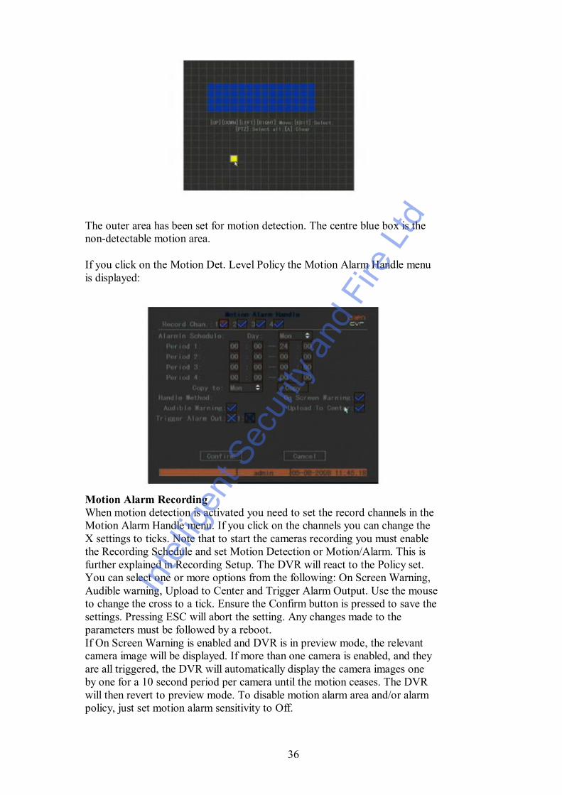
The outer area has been set for motion detection. The centre blue box is thenon-detectable motion area.
If you click on the Motion Det. Level Policy the Motion Alarm Handle menuis displayed:
Motion Alarm RecordingWhen motion detection is activated you need to set the record channels in theMotion Alarm Handle menu. If you click on the channels you can change theX settings to ticks. Note that to start the cameras recording you must enablethe Recording Schedule and set Motion Detection or Motion/Alarm. This isfurther explained in Recording Setup. The DVR will react to the Policy set.You can select one or more options from the following: On Screen Warning,Audible warning, Upload to Center and Trigger Alarm Output. Use the mouseto change the cross to a tick. Ensure the Confirm button is pressed to save thesettings. Pressing ESC will abort the setting. Any changes made to theparameters must be followed by a reboot.If On Screen Warning is enabled and DVR is in preview mode, the relevantcamera image will be displayed. If more than one camera is enabled, and theyare all triggered, the DVR will automatically display the camera images oneby one for a 10 second period per camera until the motion ceases. The DVRwill then revert to preview mode. To disable motion alarm area and/or alarmpolicy, just set motion alarm sensitivity to Off.
Inte
lligen
t Sec
urity
and
Fire
Ltd

37
5.11 Preview PropertiesIn the preview menu you can setup preview mode, screen switch time, enableor disable audio preview and preview layout.
Now click on Preview Setup and enter the Preview menu shown below.
Preview ModeIf you click on Preview Mode you can switch between a single channeldisplay and four/eight/sixteen channel display. (Dependent on model)
Preview Switch TimeThis is the Image Preview switch time. You can select between 5 seconds, 10,20, 30, 60, 120, 300 and Never. If Never is selected the preview image is notswitched automatically.
Inte
lligen
t Sec
urity
and
Fire
Ltd

38
Audio PreviewIf you enable Audio Preview by clicking on the X and changing it to a tick,when you preview a single camera, the DVR will play the audio of thatchannel.
Display DelayThe Display Delay time can be set between 1 second and 10 seconds. If youset the On Screen Warning option, when several cameras are alarmed, theDVR will show these camera images one by one for the display delay timeperiod.
Preview Layout SetupThe Layout parameter allows the camera numbers to be changed so that theorder of preview sequencing is altered. For instance clicking on the camera 1box and changing it to camera 2 automatically moves camera 1 to the secondcamera position. A small display beneath the boxes shows the new displayorder. Note that if you leave the Preview Mode in 1 Screen mode you can stillchange the order. If you press 0 the corresponding window will not displaylive video. Ensure the Confirm button is pressed to save your changes.
5.12 Recording SetupIf you select the Recording menu you will enter the Recording ChannelConfiguration menu. This is displayed below:
If HD FullThere are two options Overwrite and Stop Recording. If you select Overwritewhen the HDD is full the DVR will overwrite the earliest files recorded. If youselect Stop Recording when the HDD is full the DVR will stop recording andhandle the DVR as an exception event.
Inte
lligen
t Sec
urity
and
Fire
Ltd

39
Select CameraUse the up and down arrow keys to select the appropriate channel.
Stream TypeThere are two options Audio&Video and Video. Select Audio&Video if youwant both audio and video otherwise select Video only. You must reboot unitto make this parameter effective.
ResolutionThe DVR uses resolution settings, CIF, 2CIF and 4CIF (D1). When using 2CIF the framerate is reduced to a maximum of 12FPS and if 4CIF is selected the frame rate is reduced to6FPS. If the resolution is changed you will need to reboot the DVR.
Frame RateThe required frame rate can be selected from the following settings:1, 2, 4, 6, 8, 10, 12, 15, 16, 18, 20, 22 and 25. For low frame rate you canselect low bit rate size. The bit rate is automatically set according to the framerate selected.
Bit RateIf you select bit rate, the maximum bit rate must be limited when there are datarecording peaks. The bit rate is therefore associated to the frame rate selected.The following options can be selected: 32K, 64K, 128K, 192K, 256K, 320K,384K, 512K, 640K, 768K, 896K, 1Mbps, 1.25Mbps, 1.5Mbps, 1.75Mbps,2Mbps and By User define. For CIF resolution the typical maximum bit rate is384K ~ 768K.
Image QualityThis is set in the software and is not adjustable in the DVR. There are sixquality settings: Highest, Higher, High, Average, Low and Lowest. Highimage quality needs a high bit rate size.
Enable RecEnable or disable camera record function by changing X meaning disable totick for enabled. When enabled the Schedule option is available.
Schedule
Inte
lligen
t Sec
urity
and
Fire
Ltd

40
DayWhen the Schedule menu is entered as shown above, the Day should beselected.
All DayIf ALL Day is selected then the Period Times are switched off as recordingwill not be scheduled . If ALL Day is not selected and marked as disabled X,then the Period Times are enabled. Only select ALL Day for continuous recording.Do not select for Motion or Alarm recording.
Rec TypeThe Rec Type options are All Time, Motion Detect, Alarm, Motion|Alarm andMotion&Alarm. For all day record mode, only one record type can be selected.
Setup Time periodThere are four time periods available for each day. For each time period youcan select one of the record type options. Note: Do not overlap time periods.The time periods must run consecutively between 00:00 and 24:00.
Copy to:Allows the current page to be copied to Monday through Sunday or All.
CopyClick on this function to start the copy.
Confirm/CancelClick on confirm to save the changes and cancel to abort.NOTE: If record type is Motion Detect or other related recording types, youmust setup Motion Detection in order to trigger motion recording. Likewise ifyou set record type as Alarm or other related types, you must setup Alarms inorder to trigger alarm recording.
5.13 External Alarm Input and Relay OutputSelect the Alarms menu and the following will be displayed:
Inte
lligen
t Sec
urity
and
Fire
Ltd

41
Select Alarm InClick on this function to select alarm 1 through 4.
Alarm TypeSelect N.O (normally open) or N.C (normally closed)
Alarm HandlingSelect Handle or Ignore. Handle will display the Policy and PTZ Linkageoptions.
PolicySelect Policy and the Alarm in Handling menu will be displayed as follows:
Record CameraSelect the camera channels to record by clicking on the camera numberschanging the X disable to enabled ticked.
AlarmIn Schedule DaySelect the day Monday through Sunday.
PeriodsYou can setup up to 4 periods within each day.Note: Do not overlap time periods.The time periods must run consecutively between 00:00 and 24:00.
Copy to:Allows the current page to be copied to Monday through Sunday or All.
CopyClick on this function to start the copy.
Alarm Handle MethodYou can select one or more handle method. They are: On Screen Warning,Audible Warning, Upload to Center and Trigger Alarm Output.
Inte
lligen
t Sec
urity
and
Fire
Ltd

42
If On Screen Warning is selected and an alarm is triggered and DVR is inpreview mode, the DVR will display an image of the related camera. If morethan one camera is triggered, the DVR will display them one by one every 10seconds. When the alarm ceases the DVR will restore the preview mode.
Save setupIn the Alarm in Handling menu press Confirm button to return to the Alarmsmenu and then in the Alarms menu press Confirm to save the changes.
PTZ Linkage in Alarms menuThis function allows the alarm to trigger PTZ links. If PTZ Linkage is clickedon, the following menu is displayed:
The user must ensure that the PTZ used has the following functionality toenable these options to be used.
Select CameraFirst select the PTZ camera number. Use the up and down keys to select thechannel required.
Enable PresetClick on the Enable Preset box to switch the disable X to enable ticked.
PresetInput a preset number that has already been set in the PTZ camera.
Enable SequenceClick on the Enable Sequence box to switch the disable X to enable ticked.
Sequence No:Input a sequence number that has already been created in the PTZ camera.This is the tour/patrol/cruise sequence number.
Inte
lligen
t Sec
urity
and
Fire
Ltd

43
Press Confirm button to save and return to Alarms menu. Press Cancel or ESCto abort to return to Alarms menu.
Copy to Alarm InYou can copy contents of this alarm settings to other channels. Select thechannel.
CopyClick on this option to start the above copy.
Alarm OutThis DVR provides one alarm output for the DSD105 and four for the DSD108 andDSD116.
TimeSelect Delay Time. This is the time the relay will continue to be set after thealarm finishes triggering. Select from 5seconds, 10sec, 30sec, 1 minute, 2mins, 5mins, 10minutes and Manual. If you set Manual the alarm will not stopuntil you confirm Alarm Stop in the Utilities menu.
Alarm Out TimeIf you select the Schedule option the following menu will be displayed:
Inte
lligen
t Sec
urity
and
Fire
Ltd

44
This menu allows you to set the alarm out schedule times.
DaySelect the day of the week for the alarm output
Start Time/End TimeYou can select four periods in any one day. Do not overlap times and set timesconsecutively.
Copy to:Select other days you want to set the alarm out or all.
CopyThis allows the copy to be started.
ConfirmWhen you finish the setup press the Confirm button to save all parameters.NOTE: If any schedule is modified you must reboot the DVR to make iteffective.
Copy to Alarm OutThis DVR only provides one output alarm. Therefore this and the Copyoptions are not changeable.
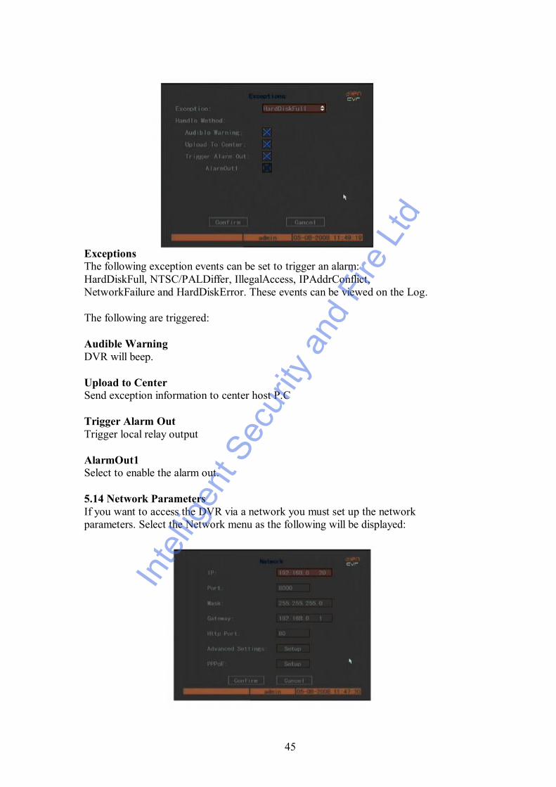
ExceptionsSelect the Exceptions menu and the following will be displayed:
Inte
lligen
t Sec
urity
and
Fire
Ltd
45
ExceptionsThe following exception events can be set to trigger an alarm:HardDiskFull, NTSC/PALDiffer, IllegalAccess, IPAddrConflict,NetworkFailure and HardDiskError. These events can be viewed on the Log.
The following are triggered:
Audible WarningDVR will beep.
Upload to CenterSend exception information to center host P.C
Trigger Alarm OutTrigger local relay output
AlarmOut1Select to enable the alarm out.
5.14 Network ParametersIf you want to access the DVR via a network you must set up the networkparameters. Select the Network menu as the following will be displayed:
Inte
lligen
t Sec
urity
and
Fire
Ltd

46
IPSet the IP address in the DVR. The IP set by the manufacturer must bechanged. Refer to the later section on setting up a network. If there is a DHCPserver in the network you can set the IP as 0.0.0.0 then Confirm and the unitwill automatically reboot using DHCP to dynamically assign an IP address,Mask and Gateway. If you then go into the Network menu, you can see the IPaddress allocated and then use this address for accessing by the local clientsoftware. If the unit still shows the IP address for the DVR as 0.0.0.0 then theDHCP server has not been found and the IP address, Mask and Gateway willhave to be set manually.
PortThe port address for the Client software.
MaskThe subnet mask used. This must be common in all equipment used on thisnetwork. This defines the size of the network and is generally 255.255.255.0
GatewayThe modem/router local address.
HTTP PortThis is set as 80 for access via Internet Explorer. This is for web access anduses ActiveX to load the software. If ActiveX security does not allow the load,then the security will have to be reduced.
Advanced SettingsIf you click on Advanced Settings Setup the following screen will bedisplayed:
Mac:This is the DVR Mac address.
Inte
lligen
t Sec
urity
and
Fire
Ltd
47
NIC TypeThe default is 10M/100M Auto. Other options that can be selected are:10M Half-Duplex, 10M Full-Dup, 100M Half-Duplex and 100M Full-Dup.Half duplex allows send and receive serially whereas full duplex allows bothsend and receive at the same time.
IP ServerIP Server address.
MCastIPThis is the multicast function. This is used for broadcasting to a range ofaddresses (224.0.0.0 ~ 239.255.255.255). If you are not using multicast thendo not set this option.
Remote Host IP & Remote Host PortIf you set this IP and port when there is an alarm and an exception eventoccurs, the DVR will send information to that host IP. The site with this IP canreceive alarm and exception event information from the DVR.
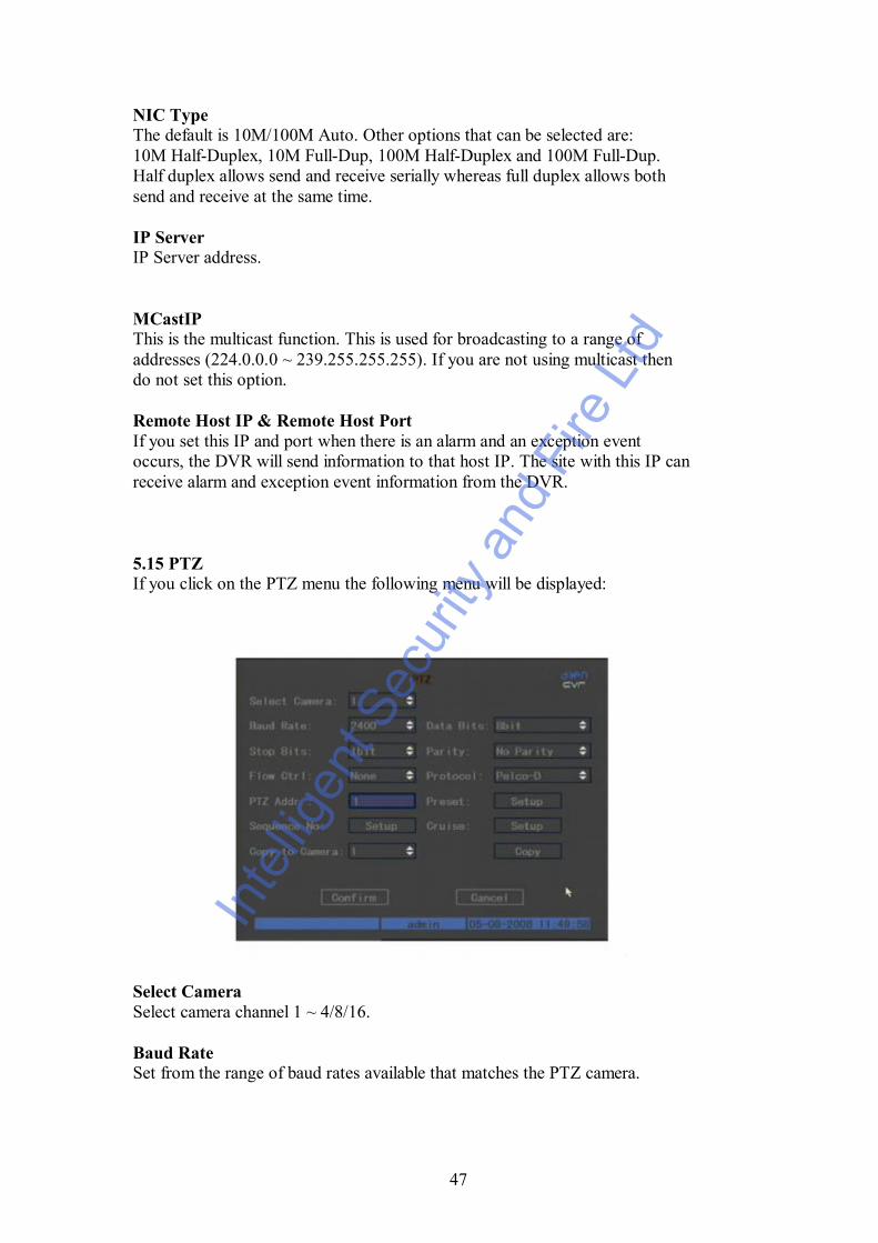
5.15 PTZIf you click on the PTZ menu the following menu will be displayed:
Select CameraSelect camera channel 1 ~ 4/8/16.
Baud RateSet from the range of baud rates available that matches the PTZ camera.
Inte
lligen
t Sec
urity
and
Fire
Ltd
48
Data Bits/Stop Bits/Parity/Flow ControlThese need to be set for the appropriate PTZ camera.
ProtocolSelect the necessary protocol used by the PTZ. There is a large list ofprotocols from which to select.
PTZ AddrSet each camera with a different address. It is easier to use the same camerachannel number. Ensure this address is set in the PTZ camera. This isnormally set by dipswitches in the camera.
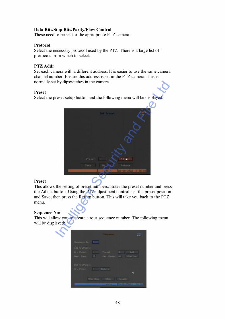
PresetSelect the preset setup button and the following menu will be displayed:
PresetThis allows the setting of preset numbers. Enter the preset number and pressthe Adjust button. Using the PTZ adjustment control, set the preset positionand Save, then press the Return button. This will take you back to the PTZmenu.
Sequence No:This will allow you to create a tour sequence number. The following menuwill be displayed:
Inte
lligen
t Sec
urity
and
Fire
Ltd
49
The sequence number will consist of a maximum of 16 presets. Each tour orcruise will have to be given a different sequence number. Each preset can beallocated a dwell speed and dwell time. The dwell time is the time the presetswaits before starting a move to the next preset. The dwell speed is the speedtaken to move from a preset to the next preset.Press the add button to add the presets in this sequence. When all details havebeen entered press Confirm to save the sequence. To test sequence press theStartSeq button and if running okay press the Stop button. This menu allowsyou to delete presets. After completing setup press Return to go back to PTZmenu then press Confirm to save all changes.
NOTE: This option will only work on PTZ units that have the featuresavailable.
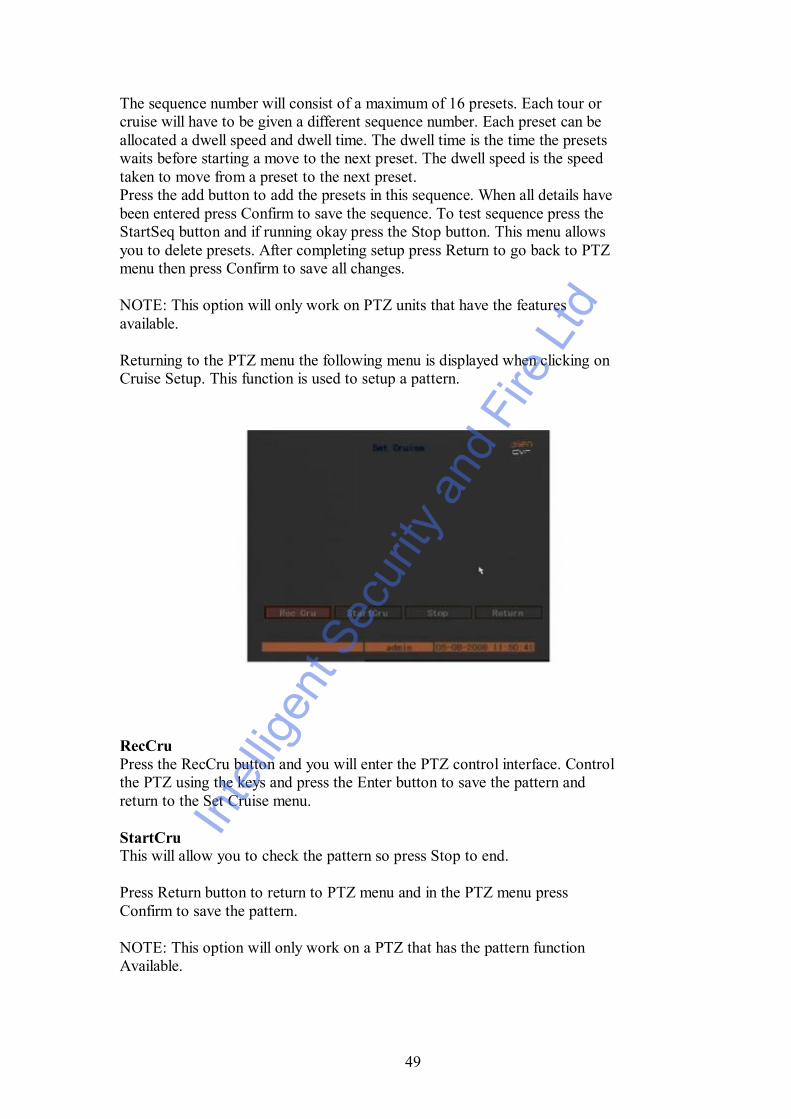
Returning to the PTZ menu the following menu is displayed when clicking onCruise Setup. This function is used to setup a pattern.
RecCruPress the RecCru button and you will enter the PTZ control interface. Controlthe PTZ using the keys and press the Enter button to save the pattern andreturn to the Set Cruise menu.
StartCruThis will allow you to check the pattern so press Stop to end.
Press Return button to return to PTZ menu and in the PTZ menu pressConfirm to save the pattern.
NOTE: This option will only work on a PTZ that has the pattern functionAvailable.
Inte
lligen
t Sec
urity
and
Fire
Ltd
50
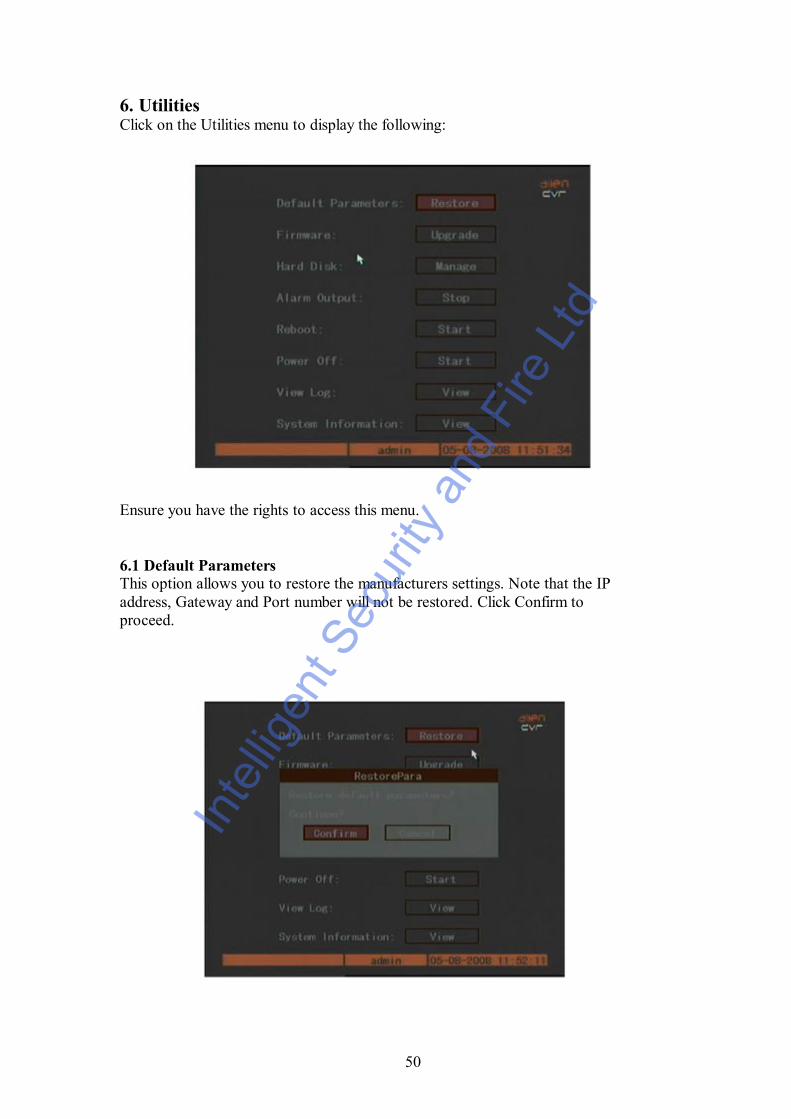
6. UtilitiesClick on the Utilities menu to display the following:
Ensure you have the rights to access this menu.
6.1 Default ParametersThis option allows you to restore the manufacturers settings. Note that the IPaddress, Gateway and Port number will not be restored. Click Confirm toproceed.
Inte
lligen
t Sec
urity
and
Fire
Ltd

51
6.2 FirmwareYou can use this option to upgrade the system firmware. Please read section 7before progressing.
You can select one of two methods to upgrade the firmware. Select eitherFTP or USB. If you select FTP mode you will enter the FTP Upgrade menu.
Input the FTP server IP address and then press Enter. The DVR will connectvia the FTP server network and download the firmware file. If you select theUSB mode, make sure you connect a USB memory stick containing thefirmware file in the root directory before selecting this option.
After the firmware upgrade completed reboot the DVR to start using the newfirmware.
SPECIAL WARNINGApplying the wrong firmware or not correctly completing a firmware upgradecan leave the unit in an unusable state. If this occurs the mainboard may haveto be shipped back to the manufacturers or replaced and this is not coveredunder the manufacturer’s warranty.
Inte
lligen
t Sec
urity
and
Fire
Ltd

52
6.3 Hard DiskThis menu provides information about the hard drives. This includes capacity,free space, standby or not and whether the status is normal or not.
FormatYou must stop all recording before formatting the drives. After formatting youmust reboot the DVR otherwise it will not perform correctly.
Enter Confirm to complete the format.
Inte
lligen
t Sec
urity
and
Fire
Ltd
53
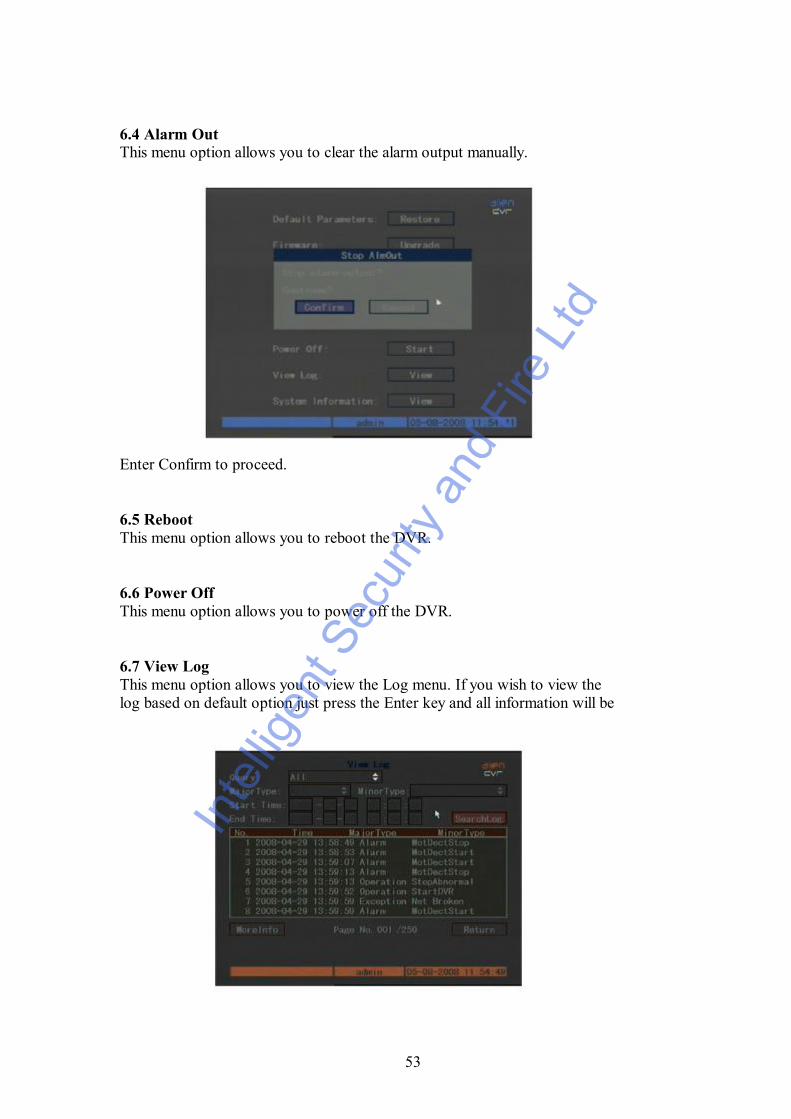
6.4 Alarm OutThis menu option allows you to clear the alarm output manually.
Enter Confirm to proceed.
6.5 RebootThis menu option allows you to reboot the DVR.
6.6 Power OffThis menu option allows you to power off the DVR.
6.7 View LogThis menu option allows you to view the Log menu. If you wish to view thelog based on default option just press the Enter key and all information will be
Inte
lligen
t Sec
urity
and
Fire
Ltd

54
Alternatively you can search options by the following:By Type, By Time or By Type&Time
By TypeThis option displays log information according to the assigned type.The type is divided into either Major Type or Minor Type. Major Typeincludes Operation, Alarm, Exception and All. Each Major Type includes anumber of Minor Types, so you can select either a Major Type or a subsetwithin a Major Type classed as a Minor Type.
OperationThis includes the following minor types:Power On, Shut Down, Abnormal Shut, Panel Login, Panel Logout, PanelConfig, Panel File Play, Panel Time Play, Local Start Record, Local StopRecord, Panel PTZ, Panel Preview, Panel Set Time, Local Upgrade, Net Login,Net Logout, Net Start Record, Net Start Transparent Channel, Net StopTransparent Channel, Net Get Parameter, Net Config, Net Get Status, NetAlert On, Net Alert Off, Net Reboot, BiComStart (Start Voice Talk), NetUpgrade, Net File Play, Net Time Play, Net PTZ.
AlarmThis includes the following minor types:External Alarm In, External Alarm Out, Motion Detect Start, Motion DetectStop, View Tamper Start, View Tamper Stop.
ExceptionThis includes the following minor types:Video Signal Loss, Illegal Access, Hard Disk Error, Hard Disk Full, IPConflict, DCD Lost.
Example - Viewing the Alarm Log.1. At Query select By Type.2. For Major Type select Alarm and for Minor Type select one of the
following:3. External Alarm In, External Alarm Out, Motion Detect Start, Motion
Detect Stop, View Tamper Start, View Tamper Stop.4. Press the SearchLog button and then press Enter to start searching.5. When search is completed DVR will list all matched alarm information.
In the List box the following information is included:Index, Occur Time, Major Type, Minor Type, Panel User, Net User,Host Address, Para. Type, Channel No., HDD No., Alarm In andAlarm Out. You can also select the MoreInfo option and page numberto show more information.
6. Press Return button to return to the Utilities menu.
Inte
lligen
t Sec
urity
and
Fire
Ltd
55
By TimeThis option allows you to view between one time period.
1. Select By Time in the Query box and select Start and Stop times.2. Press SearchLog button and then press Enter to start searching.3. DVR will display matched log information.4. Press Return to return to the Utilities menu.
By Type&TimeTo view one kind of log in an assigned time period.
1. Select By Type&Time in the Query box.2. Select Operation for the Major Type.3. Input Start and Stop time.4. Press SearchLog button and then press Enter to start searching.5. DVR will display matched log information.6. Press Return to return to the Utilities menu.
6.8 System InformationIf you select the System Information in the Utilities menu you will see thesystem configuration menu:
Inte
lligen
t Sec
urity
and
Fire
Ltd
56
7. Firmware UpgradeThe DVR firmware is stored on a Flash ROM. You can use the DVR upgradefunction to write the firmware onto flash. There are two instances when thefirmware needs to be loaded. One is to update old firmware and the other is toreload code in the DVR due to corruption.
7.1 FTP Server SetupYou can download FTP server software via the Internet. As an example we areusing wftpd32.exe:
1. Run wftpd32.exe (FTP server software)
2. Select Logging in the menu and then choose Log Options in the submenu.
3. Now select User/Rights in the Security option in the main menu.The following display will be shown:
Inte
lligen
t Sec
urity
and
Fire
Ltd

57
4. Create a new user. Select New User and a dialogue box will bedisplayed.
5. Input a user name of target and click okay.
6. In the Change Password box input password in the New Password fieldand again in the Verify Password filed. Click OK to save and exit thisbox. You will now return to the User / Rights Security Dialog box (see3. above). In the User Name box enter target and in the HomeDirectory box enter the path where the firmware file is placed. Thenpress the Done button to exit.
7. Next time you will not need to run the setup procedure again, justdouble click and open the wftpd32.exe to upgrade the firmware.
Inte
lligen
t Sec
urity
and
Fire
Ltd

58
7.2 Upgrade ModeThere are three methods for upgrading the DVR firmware. These are asfollows:
1. You can use the client software to upgrade the firmware file. You donot need to use the ftp server software. Please refer to the client software usermanual for detailed information.
2. Use the FTP function of Upgrade sub-menu in the Utilities menu. Youneed one host PC to run FTP server software and read firmware file“digicap.hex”. Make sure that the PC and DVR are in the same subnet.
3. Use the USB function of Upgrade sub-menu in the Utilities menu.Make sure the firmware file “digicap.hex” is placed under the root directory ofthe USB memory stick. For example if the memory stick shows as drive H inthe PC, the file must be seen as H:\digicap.hex.
Inte
lligen
t Sec
urity
and
Fire
Ltd

59
8. Web HTTP Operation
Please note, all the operations here are based on our 4-ch DVR.There may be differences in the interface due to different models.
8.1 Network connectionBefore web HTTP operation, please check the following items:l Network connection is correctly configuredl DVR and PC network setup is correct. Please refer to network setup in DVRl Use ping ***.***.***.*** (* DVR IP address) to check connection is OK or not.Usually the return TTL value should be less than 255.
8.1.1 Login and logoutOpen IE and input DVR address in the address column. For example, if your DVR IPis 10.1.27.200, then please input http:// 10.1.27.200 in IE address column.System may display warning information to ask you whether to install webrec.cabcontrol or not. Please click yes button.If you can’t download the ActiveX file, please modify your settings as follows. SeeFigure 0-1.
Figure 0-1 Figure 0-2
Inte
lligen
t Sec
urity
and
Fire
Ltd

60
9. Networking a Digital Video Recorder9.1 Configure the DVR to operate with a modem router.
For experienced Users
Configure the DVR as follows:a. It is assumed you have a PC working on Broadband Internet.b. Check IP address in P.C and record IP Address, Subnet Mask & Gateway
Address.Example: IP Address 192.168.0.10 Subnet: 255.255.255.000Gateway: 192.168.0.1
c. Connect LAN cable from router to DVR.d. Assign DVR a private IP address Example : 192.168.0.20
You need to assign the DVR an IP address similar to PC. The IP address youassign must be unique but the first three levels must match your local network.When configuring the DVR’s IP address information, the version of firmwarewithin the units may display the IP addresses differently. For simplicity192.168.0.20 may have to be configured as 192.168.000.020
1. Enter the DVR Menu – Go to Network Settings2 Enter Network menu3. SET IP ADDRESS (see above), Subnet Mask: 255.255.255.000 (example),
GATEWAY 192.168.0.1 (example - Router local address), Service Port 8000,HTTP Port 80, Protocol TCP and SAVE.
4. EXIT MENU.5. Now turn Router off and on. This will take about one minute to reset.6. Your DVR is now ready for access via the local PC using the Client Software.7. Refer to your modem/router manual for instructions on how to configure it to
allow incoming Internet access.8. If you fail to access DVR check all steps again.
Inte
lligen
t Sec
urity
and
Fire
Ltd
61
9.2 For Beginners
You must be able to perform some basic tasks in order to connect your Digital VideoRecorder to a PC and subsequently the Internet.
The following page describes some simple tasks but more help is available online atwww.systemq.com so before you start please download the following tips from thewebsite ‘Online Support’ section –
Tip 117 Describing how to set a PCs IP AddressTIP 36 Describing how to perform ‘ping’ testTip 58 Describing how to configure a router for Internet access
The diagrams that follow suggest settings that if used will result in a successfulconnection.
Bear in mind that when it comes to Option 3 for Internet use, different routermanufacturers may not use the exact settings given here so slight adjustments may benecessary.
Inte
lligen
t Sec
urity
and
Fire
Ltd
62
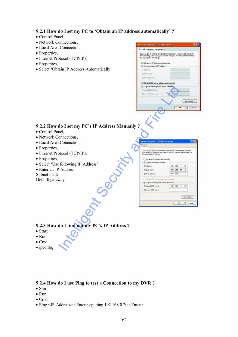
9.2.1 How do I set my PC to ‘Obtain an IP address automatically’ ?· Control Panel,· Network Connections,· Local Area Connection,· Properties,· Internet Protocol (TCP/IP),· Properties,· Select ‘Obtain IP Address Automatically’
9.2.2 How do I set my PC’s IP Address Manually ?· Control Panel,· Network Connections,· Local Area Connection,· Properties,· Internet Protocol (TCP/IP),· Properties,· Select ‘Use following IP Address’· Enter … IP AddressSubnet maskDefault gateway
9.2.3 How do I find out my PC’s IP Address ?· Start· Run· Cmd· ipconfig
9.2.4 How do I use Ping to test a Connection to my DVR ?· Start· Run· Cmd· Ping <IP-Address> <Enter> eg: ping 192.168.0.20 <Enter>
Inte
lligen
t Sec
urity
and
Fire
Ltd

63
9.2.5 How do I Configure a Router for Remote Access ?· Instructions on the SystemQ website cover the NET800 and Netgear Routers
9.2.6 How do I find the On-Line Support ?http://www.systemq.com/cgi-bin/commerce.exe?display=user2
Detailed descriptions are available there for all these questions plus more besides,including …
· How to find a device’s MAC address (Tip 3)· How to implement Dynamic DNS (Tip 56)· Setting Internet Explorer Security Settings to install an Active-X (Tip 94)· How to control a PTZ from a DVR· How to play back recordings from various DVRs· Links for downloading client software packages
Inte
lligen
t Sec
urity
and
Fire
Ltd
64
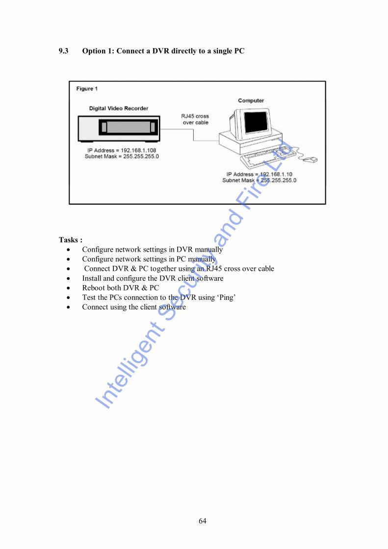
9.3 Option 1: Connect a DVR directly to a single PC
Tasks : · Configure network settings in DVR manually · Configure network settings in PC manually · Connect DVR & PC together using an RJ45 cross over cable · Install and configure the DVR client software · Reboot both DVR & PC · Test the PCs connection to the DVR using ‘Ping’ · Connect using the client software
Inte
lligen
t Sec
urity
and
Fire
Ltd

65
9.4 Option 2: Connect a DVR to a switch or hub
Tasks :· Configure network settings in DVR manually· Configure network settings in PC manually· Connect DVR & PC together using an RJ45 cross over cable· Install and configure the DVR client software· Reboot both DVR & PC· Test the PCs connection to the DVR using ‘Ping’· Connect using the client software
Inte
lligen
t Sec
urity
and
Fire
Ltd

66
9.5 Option 3: Connecting for Internet Access
Important Notes :If using a BT phone line you must use an ADSL modem router, if using a NTL orcable phone service you must use an appropriate cable router.
Be aware that when connected to the internet, the router has two IP addresses: internaland external. The internal address is seen by devices connecting to it’s Ethernet ports,the external address represents it’s connection to the local exchange via the telephoneline.
You can only test an external Internet connection from a PC not connected locally tothe modem/router.
Inte
lligen
t Sec
urity
and
Fire
Ltd
67
Tasks : · Find out what the external IP address is, this is assigned by the customer’s
Internet Service Provider · Find out : is this a fixed IP address, ie: “Static, or does it change, ie:
“Dynamic” ? · Configure network settings in the DVR manually · Configure network settings in the PC to “Obtain IP Address Automatically” if
possible, if not, then configure manually · Connect DVR & PC to the modem/router using patch cables · Install and configure the DVR client software · Reboot both DVR & PC · Test the PCs connection to the DVR using ‘Ping’ · Use the client software to connect to the DVR from the local PC · Ensure the PC has outbound Internet access · Configure the modem router for inbound access using either “Port
Forwarding”, or “DMZ” · Ask a colleague offsite to test Internet access by connecting to the router’s
external IP address
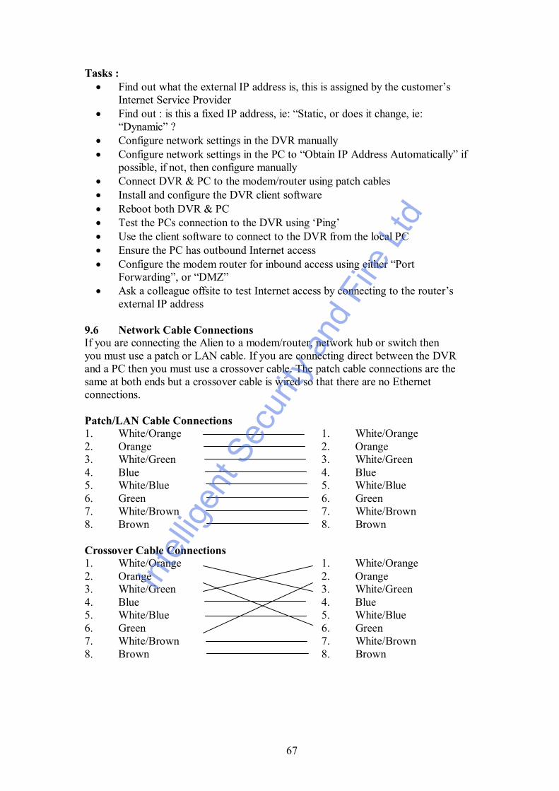
9.6 Network Cable ConnectionsIf you are connecting the Alien to a modem/router, network hub or switch thenyou must use a patch or LAN cable. If you are connecting direct between the DVRand a PC then you must use a crossover cable. The patch cable connections are thesame at both ends but a crossover cable is wired so that there are no Ethernetconnections.
Patch/LAN Cable Connections1. White/Orange 1. White/Orange2. Orange 2. Orange3. White/Green 3. White/Green4. Blue 4. Blue5. White/Blue 5. White/Blue6. Green 6. Green7. White/Brown 7. White/Brown8. Brown 8. Brown
Crossover Cable Connections1. White/Orange 1. White/Orange2. Orange 2. Orange3. White/Green 3. White/Green4. Blue 4. Blue5. White/Blue 5. White/Blue6. Green 6. Green7. White/Brown 7. White/Brown8. Brown 8. Brown
Inte
lligen
t Sec
urity
and
Fire
Ltd

68
Inte
lligen
t Sec
urity
and
Fire
Ltd

69
Appendix B - DVR Recording Times in Days
CIF MODE - DSD106 4 CHANNEL DVR - RECORDING TIME PER CHANNEL
FPS Gb/Hr Gb/Hr Channel Machine 80Gb 160Gb 250Gb 300Gb 750Gb 1Tb
25 0.24 0.97 3.4 6.8 10.7 12.8 32.1 41.25
20 0.23 0.93 3.6 7.2 11.2 13.4 33.5 47.12
16 0.20 0.79 4.2 8.4 13.2 15.8 39.5 54.9
12 0.13 0.52 6.4 12.9 20.1 24.2 60.4 82.38
8 0.10 0.38 8.7 17.4 27.1 32.5 81.3 109.9
6 0.06 0.25 13.3 26.6 41.5 49.8 124.5 164.87
4 0.05 0.19 17.4 34.7 54.2 65.1 162.7 219.8
2 0.02 0.10 35.0 69.9 109.2 131.1 327.7 439.7
1 0.01 0.05 52.5 105.1 164.2 197.1 492.6 659.55
QCIFThis DVR is capable of recording in QCIF. QCIF is approximately one quarter of CIFso resolution is very low. The storage space provided however is increased by fourtimes and an estimate of record time in days can be calculated by multiplying theabove CIF recording time by four.
SPECIAL NOTEThe recording times stated above are only an estimated calculation based on averagefile sizes of each frame recorded to Hard Drive. As file sizes can change according tovariation in colours and complexity of the video image captured, MPEG4/H264reduce storage space according to effective changes between current and previousimage. Therefore please only take the above recording times as a rough estimate.In
tellig
ent S
ecur
ity a
nd F
ire L
td

70
Appendix C – QUICK HELP GUIDE (OPERATIONS MENU)
FUNCTION PAGE PRIME MENU SECONDARYMENU
FUNCTION
SWITCH OFF PASSWORD 29 DISPLAY PUT X IN REQUIREPASSWORD BOXCONFIRM DISPLAY
DATE/TIME 29 DISPLAYTHEN SETUP ENTER TO SAVE
CONFIRM DISPLAYPLAYBACK 20 PRESS PLAY
BUTTONENTER USER &PASSWORDPRESS EDIT
ENTER CHANNELENTER REC TYPEENTER TIME REQCLICK SEARCHUSE UP/DOWN ARROWBUTTONS TO SELECTPRESS PLAY
BACKUP 20/21 PRESS PLAYBUTTON AFTERINSTALLINGBACKUP MEDIA
ENTER CHANNELENTER REC TYPEENTER TIME REQCLICK SEARCHUSE UP/DOWN ARROWBUTTONS TO SELECTPRESS BACKUP
MOTION DETECTION 35
38
CAMERA
RECORDING
AREA
DESELECTALL DAY
SET MOTION DET LEVEL0 = LOW 5 = HIGHPRESS CONFIRMPRESS PTZ TO SELECTALL OR PRESS A TOCLEAR ALLPRESS EDIT & TO SETUPAREAS USE ARROWKEYSPRESS SAVE THENCONFIRM AREACONFIRM CAMERA
CONFIRMPREVIEW/SEQUENCING 37 DISPLAY
SELECTPREVIEWSETUP PREVIEW SWITCH 1 – 4 CHANNEL
SELECT SEQUENCINGCONFIRM PREVIEWCONFIRM DISPLAY
RECORDING SETUP 38
39
RECORDING
RECORDINGCHANNELCONFIG
SCHEDULE
HD FULLOVERWRITE
CIF/QCIF
FRAME RATE
ENABLE REC
SET SCHEDULECONFIRM SCHEDULECONFIRM RECORD
AUDIO 38
37/39
RECORDING
DISPLAY &SELECTPREVIEWSETUP
PREVIEW
SET STREAM TYPE TOAUDIO&VIDEOCONFIRM RECORD
SET AUDIO BY TICKINGAUDIO PREVIEWCONFIRM PREVIEWCONFIRM DISPLAY
NETWORK PARAMS 45/47 NETWORK SET IP, PORT, SUBNETMASK, GATEWAY, HTTPPORT.CONFIRM NETWORK
Inte
lligen
t Sec
urity
and
Fire
Ltd

71
PTZ
CONNECT RS485
PTZ PRESETS
TOUR SETUP
RUN TOUR
PATTERN SETUP
RUN PATTERN
47
8
47/49
47/49
48/49
49
49
PTZ
T+ T-
PTZSET PRESETSSELECT PRESETSETUP
PTZSEQUENCE NO:SETUP
PTZSEQUENCE NO:SETUP
PTZCRUISE SETUP
PTZCRUISE SETUP
SET PRESET
SEQUENCE
SEQUENCE
SET CRUISEPRESS REC CRU
SET CRUISEPRESS STARTCRU
SET CHANNEL, BAUDRATE, PROTOCOL,ADDR.CONFIRM PTZ
CONNECT A LINE + TOT+ & B LINE – TO T-
SET PRESET POINTSCONFIRM SET PRESETCONFIRM PTZ
CREATE TOURCONFIRM SEQUENCECONFIRM PTZ
ENTER TOUR NUMBER(SEQUENCE)STARTSEQ/STOPRETURN
ENTER PTZ CONTROL &USE KEYS TO CREATEPATTERN, THEN PRESSENTER TO SAVEPATTERNRETURNCONFIRM PTZ
RETURNUTILITIES 50 UTILITIES DEFAULT
HARD DISKMANAGE
REBOOT
POWER OFF
VIEW LOG
SYSTEM INFO
PRESS RESTORE
HDD INFO & FORMAT
REBOOT
POWER OFF
VIEW LOG
SYSTEM INFOUSERNAME, PASSWORD &RIGHTS
25/29 PRESS MENU PASSWORD CHANGESLOCAL RIGHTSREMOTE RIGHTS
VGA & VIDEO MODE 29 DISPLAY VIDEOSTANDARD
VGA RESOLUT.
SET TO PAL MODE
SELECT RESOLUTION
CONFIRMCANCEL BEEP SOUND 9 PRESS MENU
FOR >5 SECSDISABLES BEEPER
COVERT CAMERA
SET NEW USER PASSWORD
REBOOT M/C & LOGON TO NEW USER
OPEN DISPLAY MENU
25/29
37
PRESS MENU
DISPLAY PREVIEWSETUP
SET OFF LOCAL/REMOTEDISPLAY RIGHTS
INPUT 0 TO CHANNEL
Inte
lligen
t Sec
urity
and
Fire
Ltd

72
Appendix D - Specifications
Model Number DSD106Video Compression MPEG4/H264Resolution PAL: 352 * 288 CIF 176 * 144 QCIFPlayback Resolution CIF / QCIFVideo Input 4 channelsVideo Input BNC 1.0v p~p 75 ohmsVideo Output 2 composite video outputsLoop throughs NoneFrame Rate 100 FPSMax Bit Rate 32Kbps ~ 2MbpsAudio Input 1 ch RCA 600 ohmsAudio Output 1 ch RCA 600 ohmsAudio Compression Ogg VorbisComms Interface 1 * RJ45 10M/100M Ethernet InterfaceTalkback Function 2way
Talkback 2 way audio
USB Interface USB1.1 - supports memory stick, USB HDD, USB CD-RW,USB DVD-RW
VGA Interface Supports 800*600/60Hz, 800*600/75Hz, 1024*768/60HzExternal Alarms In 4 alarm inputsRelay Output 1 alarm outputHDD specs Internal SATA HDD Maximum 1 TbPower Supply 240vAC 12vDC 3.3AmpPower Consumption 12vDC 40 wattsWorking Temp. -10ºC ~ +55ºCWorking Humidity 10% ~ 90%Size W200mm x D275mm x H130mm
Inte
lligen
t Sec
urity
and
Fire
Ltd


