Send Orders for Reprints to [email protected]The Open Construction and Building Technology Journal, 2016, 10, 525-537 525 1874-8368/16 2016 Bentham Open The Open Construction and Building Technology Journal Content list available at: www.benthamopen.com/TOBCTJ/ DOI: 10.2174/1874836801610010525 RESEARCH ARTICLE Experimental Study on Properties of Steel-plastic Geogrids and their Application in Supporting Engineering Qingbiao Wang *, 1,2,3 , Rongshan Lü 1 , Yingchun Kong 1 , Lingyu Tang 1 , Fei Xie 1 , Qingli Kong 1 , Junjie Zhang 1 , Tangsha Shao 1 , Qingkai Zhu 1 , Shuyi Xu 1 , Zhongjing Hu 1 , Yun Bai 1 , Xunmei Liang 3 and Shide Lu 3 1 College of Civil Engineering and Architecture, Shandong University of Science and Technology, Qingdao Shandong 266590, China 2 Department of Resource and Civil Engineering, Shandong University of Science and Technology, Tai’an, Shandong 271019, China 3 Tai’an Road Engineering Materials Co., Ltd., Tai’an, Shandong, 271019, China Received: July 14, 2016 Revised: September 15, 2016 Accepted: September 30, 2016 Abstract: Steel-plastic geogrid greatly improves the stability of surrounding rock in the supporting project due to the qualities, such as high strength, high toughness and less creep deformation. Through the geogrid mechanical properties analysis, tensile strength, deformation and creep test and field experiment and so on, we researched and analyzed steel-plastic geogrids’ characteristics and supporting effect, and concluded the influencing factors of steel-plastic geogrids’ characteristics, load-time curve and the steel-plastic geogrids’ variation under different temperature. We explained steel-plastic geogrids’ supporting effect through specific examples of projects. The results of the studies are listed as follows: (1) Steel-plastic geogrid has good resistance to deformation and node failure of roadway surrounding rock deformation, which has good tensile property, creep property and deflection performance; (2) It is feasible to support the surrounding rock by forming a whole combined joint support with steel- plastic geogrid and high-strength prestressed anchor rod. Keywords: Creep, Deflection, Mechanical properties, Plastic geogrid, Rock support, Tensile properties. 1. INTRODUCTION With the advantages of high strength, good durability, convenient construction, geogrid has been widely used in highway, railway, mine and other fields. When it is applied as supporting structure, geogrid mainly through its tensile strength to bear the load from the soil plays a role of the project. But as a kind of new material, research on the mechanical properties is still at the beginning stage. Similarly, steel grating in roadway support applied research is still blank. A lot of people have studied the application of metal mesh as the anchor net in support. But almost no one is involved in the application of the steel plastic geogrid as anchor net support. In the 1960s, L.V. Rabcewic [ 1] summarized and put forward a new construction method for Austria tunnel with many years' experiences of tunnel engineering construction in Austria. The construction method of flexible support and active support method, the soft rock roadway has a certain guiding significance, has been widely used in the design and construction of underground engineering Based on the classical elastic-plastic theory of surrounding rock, many scholars have carried out a lot of research and improvement in the domestic and international [2, 3]. * Address correspondence to this author at the Department of Resource and Civil Engineering, Shandong University of Science and Technology, Tai’an, Shandong 271019, China; Tel: +8618805381111; E-mail: [email protected]
1College of Civil Engineering and Architecture, Shandong University of Science and Technology, Qingdao Shandong266590, China2Department of Resource and Civil Engineering, Shandong University of Science and Technology, Tai’an, Shandong271019, China3Tai’an Road Engineering Materials Co., Ltd., Tai’an, Shandong, 271019, China
Received: July 14, 2016 Revised: September 15, 2016 Accepted: September 30, 2016
Abstract: Steel-plastic geogrid greatly improves the stability of surrounding rock in the supporting project due to the qualities, suchas high strength, high toughness and less creep deformation. Through the geogrid mechanical properties analysis, tensile strength,deformation and creep test and field experiment and so on, we researched and analyzed steel-plastic geogrids’ characteristics andsupporting effect, and concluded the influencing factors of steel-plastic geogrids’ characteristics, load-time curve and the steel-plasticgeogrids’ variation under different temperature. We explained steel-plastic geogrids’ supporting effect through specific examples ofprojects. The results of the studies are listed as follows: (1) Steel-plastic geogrid has good resistance to deformation and node failureof roadway surrounding rock deformation, which has good tensile property, creep property and deflection performance; (2) It isfeasible to support the surrounding rock by forming a whole combined joint support with steel- plastic geogrid and high-strengthprestressed anchor rod.
With the advantages of high strength, good durability, convenient construction, geogrid has been widely used inhighway, railway, mine and other fields. When it is applied as supporting structure, geogrid mainly through its tensilestrength to bear the load from the soil plays a role of the project. But as a kind of new material, research on themechanical properties is still at the beginning stage. Similarly, steel grating in roadway support applied research is stillblank.
A lot of people have studied the application of metal mesh as the anchor net in support. But almost no one isinvolved in the application of the steel plastic geogrid as anchor net support. In the 1960s, L.V. Rabcewic [1]summarized and put forward a new construction method for Austria tunnel with many years' experiences of tunnelengineering construction in Austria. The construction method of flexible support and active support method, the softrock roadway has a certain guiding significance, has been widely used in the design and construction of undergroundengineering Based on the classical elastic-plastic theory of surrounding rock, many scholars have carried out a lot ofresearch and improvement in the domestic and international [2, 3].
* Address correspondence to this author at the Department of Resource and Civil Engineering, Shandong University of Science and Technology,Tai’an, Shandong 271019, China; Tel: +8618805381111; E-mail: [email protected]
526 The Open Construction and Building Technology Journal, 2016, Volume 10 Wang et al.
On the base of the experimental research, Tannant. D. D. [4, 5] studied the welding wire mesh reinforcement, andfound that the net in the anti-deformation ability depended on the plate shape and plate relative to the nets in thedirection, and the mesh number of the load transfer located in the pallet. Since the 90’s in twentieth century, thedevelopment of the domestic and international has been gradually developed with the support of the cable and theanchor net belt [6 - 9]. By using bolt support on the initial pressure of the surrounding rock to support the foundation,strength and stiffness of the two supporting measures increase to jointly support the surrounding rock stress, this byimproving the supporting strength to maintain the long-term stability of the tunnel. Supporting measures were taken tothe anchor, grouting and sealing metal bracket or concrete lining structure to form a different form of joint support [10 -14].
In view of the metal mesh selection and network method in coal mine bolt mesh shotcrete support, Lin Jian and SunZhiyong [15] used laboratory test method to study the stress state, deformation condition and supporting function of thecommon metal mesh of the bolt support. According to the bolt fracture, appeared in Dongtan coal mine roof net localroadway deformation serious tear strip even collapse, Deng Xiaolin [16] optimizes the anchor net support technology indeep well. Therefore, combined with a variety of theories and methods, research on mechanical properties of steelgrating and the supporting effect is very necessary.
From the above results, we know that there are almost no researches of the steel-plastic geogrids as the anchor of thesupporting mechanism and method. Therefore, this paper introduced tests and analysis of steel-plastic geogrids’ tensilestrength, deflection performance and creep performance. Steel-plastic geogrid was applied successfully in roadway, andit was verified that the steel-plastic geogrids could replace metal mesh to support in roadway.
2. OVERVIEW OF PLASTIC GEOGRID
2.1. Concept and Scope of Application
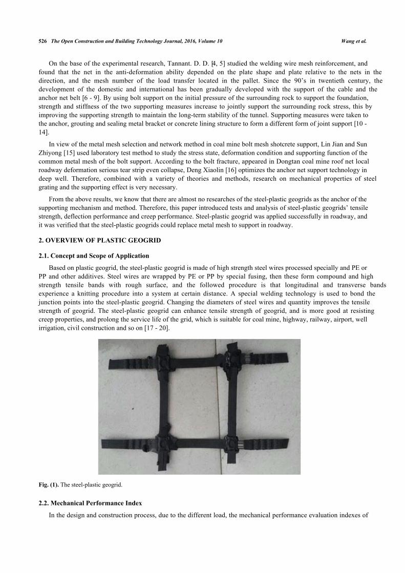
Based on plastic geogrid, the steel-plastic geogrid is made of high strength steel wires processed specially and PE orPP and other additives. Steel wires are wrapped by PE or PP by special fusing, then these form compound and highstrength tensile bands with rough surface, and the followed procedure is that longitudinal and transverse bandsexperience a knitting procedure into a system at certain distance. A special welding technology is used to bond thejunction points into the steel-plastic geogrid. Changing the diameters of steel wires and quantity improves the tensilestrength of geogrid. The steel-plastic geogrid can enhance tensile strength of geogrid, and is more good at resistingcreep properties, and prolong the service life of the grid, which is suitable for coal mine, highway, railway, airport, wellirrigation, civil construction and so on [17 - 20].
Fig. (1). The steel-plastic geogrid.
2.2. Mechanical Performance Index
In the design and construction process, due to the different load, the mechanical performance evaluation indexes of
Experimental Study on Properties of Steel-plastic The Open Construction and Building Technology Journal, 2016, Volume 10 527
steel-plastic geogrids are also different. The mechanical properties of the steel-plastic geogrid (Fig. 1) include tensilestrength, friction test intensity, tensile strength and the interaction between the fillers and so on [21]. The Mechanicalperformance indexes are shown in Tables 1 and 2.
Table 1. Main index of the 0.7mmx12 geogrids.
Project Type and SpecificationVertical (horizontal) to tensile strength (kN/m) ≥ 128.0
The tensile strength of the 2% longitudinal strain(kN/m) ≥ 30.4The tensile strength of the 5% longitudinal strain(kN/m) ≥ 61.2
Considering that the support effect is influenced by different temperatures, loads and fillers in engineeringapplication, the tensile properties of geogrid are different. Therefore, the test of single and double geogrids pull out testof the above mentioned factors is carried out, and the strength of the steel-plastic geogrids is studied [22].
3.1. Tensile Strength
The steel-plastic geogrid is a flexible material, and the tensile strength is the main characteristic of the material ofthe synthetic material. The main parameters include that: the tensile strength of the longitudinal and transverse tensilestrength is far greater than 50kN/m, the longitudinal and transverse elongation are no more than 13%, and the tensilestrength of the elongation at 5% is much greater than 35kN/m.
In order to study the effect of different tensile rates on the tensile properties of steel-plastic geogrids, we selectedthree kinds of different specifications of the steel plastic geogrids in the uniform and different strain rates (50, 10, 1, 0.1,0.05mm/min) of tensile in experiment research. Test equipment was used for the DR028J universal material testingmachine. The experiment was carried out at (20 + 2)°C constant temperature and (60 + 5)% relative humidityconditions, and used the fixture to clamp the steel-plastic geogrid by the universal testing machine. The wholeexperiment process is controlled by universal testing machine.
Fig. (2). Tensile test result of geogrids at a steady speed.
As we can see from Fig. (2), the four groups of steel-plastic geogrid stretching process can be roughly divided intothree stages: low load and large deformation stage, stage of small high load deformation and fracture stage. At thebeginning of loading process low load and large deformation stage: tensile load was small, the displacement of tensiledeformation was large, and 4 groups had reached the final tensile testing of about 19 mm; and then had entered thesecond stage high load small deformation stage. In this stage, with the increase of loading, the displacement anddeformation of geogrid were increasing gradually. It could be seen from the Fig. (2), the tensile curves increased, but atthe same change of loading, the displacement of the second phase is smaller than the first stage, and tensile maximumlength of the NO.1 group is only 6mm; when the loading exceeded 11kN, the four groups had entered the third stage
5 10 15 20 25 300
2000
4000
6000
8000
10000
12000
14000
NO.4
NO.3 NO.2
Stre
ss(k
N)
Displacement(mm)
NO.1
528 The Open Construction and Building Technology Journal, 2016, Volume 10 Wang et al.
fracture stage: in this stage, the wires were destroyed by root, the tensile curve decreased, and the tensile strengthdecreased rapidly until 0. It could be known from the analysis: the tensile strength of steel-plastic geogrid wasinfluenced obviously by steel wires, and wires were destroyed, thereby decreasing the geogrid tensile strength.
Table 2. Mechanical properties of bidirectional steel plastic geogrid.
TypePer meter tensile yield
≥(kN/m) Nominal elongation rate≤(%) The tensile force at 2% elongation ≥(kN/m)Width(m)
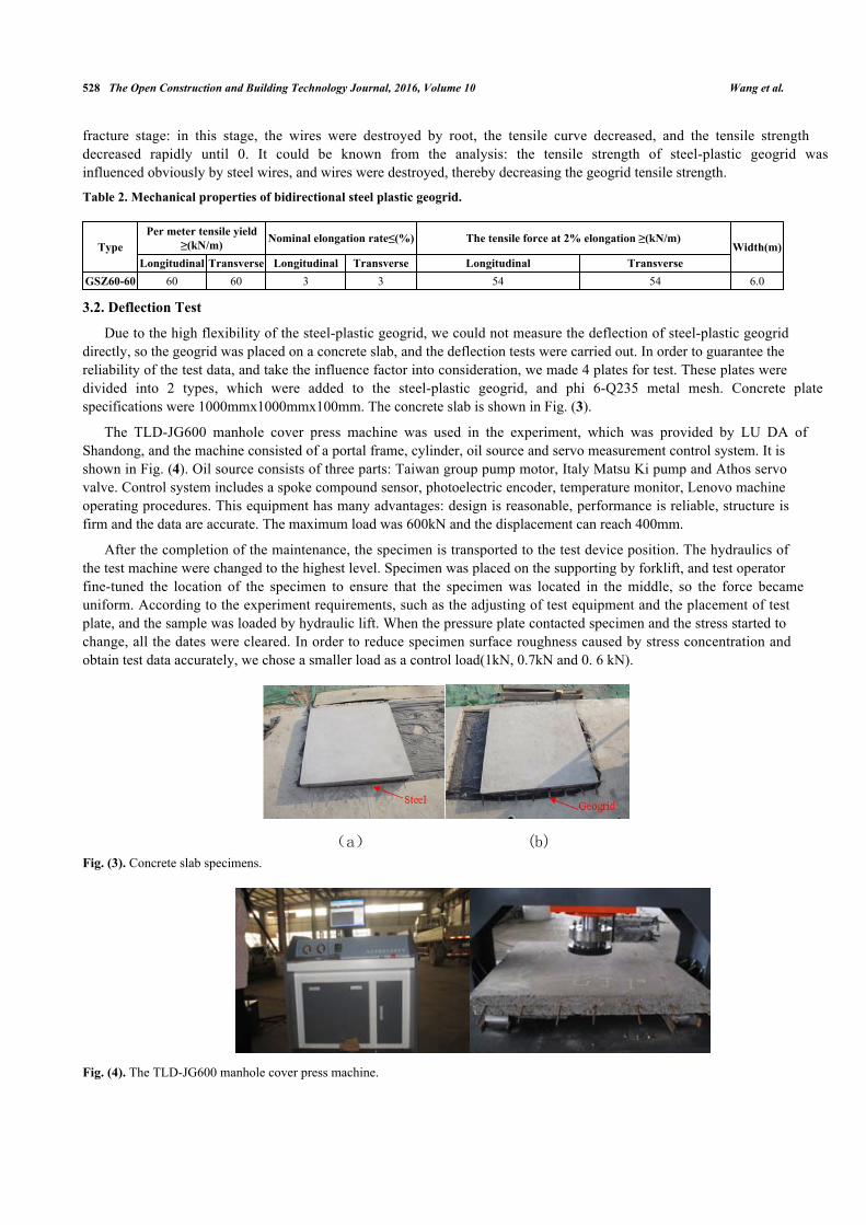
Due to the high flexibility of the steel-plastic geogrid, we could not measure the deflection of steel-plastic geogriddirectly, so the geogrid was placed on a concrete slab, and the deflection tests were carried out. In order to guarantee thereliability of the test data, and take the influence factor into consideration, we made 4 plates for test. These plates weredivided into 2 types, which were added to the steel-plastic geogrid, and phi 6-Q235 metal mesh. Concrete platespecifications were 1000mmx1000mmx100mm. The concrete slab is shown in Fig. (3).
The TLD-JG600 manhole cover press machine was used in the experiment, which was provided by LU DA ofShandong, and the machine consisted of a portal frame, cylinder, oil source and servo measurement control system. It isshown in Fig. (4). Oil source consists of three parts: Taiwan group pump motor, Italy Matsu Ki pump and Athos servovalve. Control system includes a spoke compound sensor, photoelectric encoder, temperature monitor, Lenovo machineoperating procedures. This equipment has many advantages: design is reasonable, performance is reliable, structure isfirm and the data are accurate. The maximum load was 600kN and the displacement can reach 400mm.
After the completion of the maintenance, the specimen is transported to the test device position. The hydraulics ofthe test machine were changed to the highest level. Specimen was placed on the supporting by forklift, and test operatorfine-tuned the location of the specimen to ensure that the specimen was located in the middle, so the force becameuniform. According to the experiment requirements, such as the adjusting of test equipment and the placement of testplate, and the sample was loaded by hydraulic lift. When the pressure plate contacted specimen and the stress started tochange, all the dates were cleared. In order to reduce specimen surface roughness caused by stress concentration andobtain test data accurately, we chose a smaller load as a control load(1kN, 0.7kN and 0. 6 kN).
Fig. (3). Concrete slab specimens.
Fig. (4). The TLD-JG600 manhole cover press machine.
(a) (b)
Experimental Study on Properties of Steel-plastic The Open Construction and Building Technology Journal, 2016, Volume 10 529
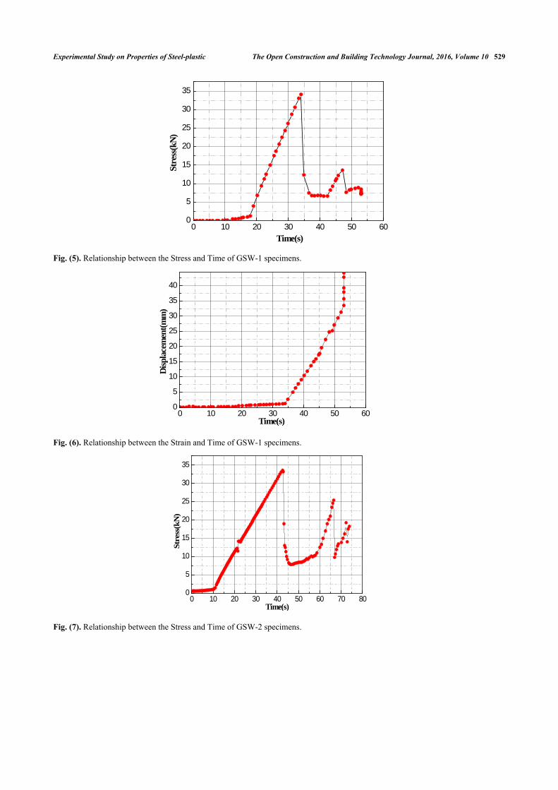
Fig. (5). Relationship between the Stress and Time of GSW-1 specimens.
Fig. (6). Relationship between the Strain and Time of GSW-1 specimens.
Fig. (7). Relationship between the Stress and Time of GSW-2 specimens.
0 10 20 30 40 50 600
5
10
15
20
25
30
35
Stre
ss(k
N)
Time(s)
0 10 20 30 40 50 600
5
10
15
20
25
30
35
40
Disp
lace
men
t(mm
)
Time(s)
0 10 20 30 40 50 60 70 800
5
10
15
20
25
30
35
Stre
ss(k
N)
Time(s)
530 The Open Construction and Building Technology Journal, 2016, Volume 10 Wang et al.
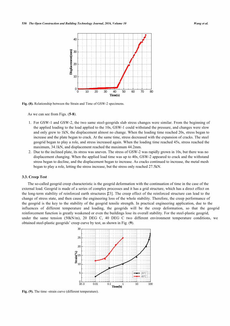
Fig. (8). Relationship between the Strain and Time of GSW-2 specimens.
As we can see from Figs. (5-8).
For GSW-1 and GSW-2, the two same steel-geogrids slab stress changes were similar. From the beginning of1.the applied loading to the load applied to the 10s, GSW-1 could withstand the pressure, and changes were slowand only grew to 1kN, the displacement almost no change. When the loading time reached 20s, stress began toincrease and the plate began to crack. At the same time, stress decreased with the expansion of cracks. The steelgeogrid began to play a role, and stress increased again. When the loading time reached 45s, stress reached themaximum, 34.1kN, and displacement reached the maximum 44.2mm.Due to the inclined plate, its stress was uneven. The stress of GSW-2 was rapidly grown in 10s, but there was no2.displacement changing. When the applied load time was up to 40s, GSW-2 appeared to crack and the withstandstress began to decline, and the displacement began to increase. As cracks continued to increase, the metal meshbegan to play a role, letting the stress increase, but the stress only reached 27.5kN.
3.3. Creep Test
The so-called geogrid creep characteristic is the geogrid deformation with the continuation of time in the case of theexternal load. Geogrid is made of a series of complex processes and it has a grid structure, which has a direct effect onthe long-term stability of reinforced earth structures [23]. The creep effect of the reinforced structure can lead to thechange of stress state, and then cause the engineering loss of the whole stability. Therefore, the creep performance ofthe geogrid is the key to the stability of the geogrid tensile strength. In practical engineering application, due to theinfluences of different temperature and loading, the geogrids will be the creep deformation, so that the geogridreinforcement function is greatly weakened or even the buildings lose its overall stability. For the steel-plastic geogrid,under the same tension (50kN/m), 20 DEG C, 40 DEG C two different environment temperature conditions, weobtained steel-plastic geogrids’ creep curve by test, as shown in Fig. (9).
Fig. (9). The time -strain curve (different temperature).
0 10 20 30 40 50 60 70 800
10
20
30
40
Disp
lace
men
t(mm
)
Time(s)
1E-3 0.01 0.1 1 10 1000
5
10
15
20
25
30
Stra
in(%
)
Time(h)
20℃ 40℃
Experimental Study on Properties of Steel-plastic The Open Construction and Building Technology Journal, 2016, Volume 10 531
Through the analysis of Fig. (9), we could know that the strain spent 100 hours reaching 20 at 20 DEG C, but in 40DEG C, only 0.5 hours is enough. The temperature had a great influence on steel-plastic geogrids’ creep, and the strainvalue increased with the increasing of temperature.
4. SUPPORT THEORIES
Anchor net support mainly use prestressed anchor (resin bolt, an end anchor head mechanical bolt) and anchor(metal), the selected anchoring force should be very strong, which can carry real time, after installation of surroundingrock prestressing [24].
In the broken soft rock roadway, bolt support is difficult to form a stable and effective load bearing structure, whichis difficult to control the strong deformation of this kind of roadway, and it is not enough to ensure the overall stabilityof the roadway. Elastic-plastic theory analysis method is to study the deformation and failure of roadway surroundingrock, and is the most original and one of the most classical methods, which is the theoretical basis of the research on thedeformation and failure mechanism of roadway surrounding rock [25 - 29].
The roadway surrounding rock is generally in a low confining pressure environment, and under this condition, thestrain softening phenomenon generally occurs. The correlation test [30, 31] showed that the residual strength increasedwith the increase of confining pressure, and it showed a strong sensitivity to confining pressure.
Metal frame is the most commonly used method in soft rock tunnel. It is through the provision of passive radialsupport force, directly acting on the surface of the roadway surrounding rock, to balance the deformation of thesurrounding rock, the surrounding rock deformation. Support technology is a common form of support in deep rockroadway [32 - 39].
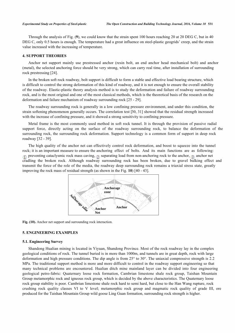
The high quality of the anchor net can effectively control rock deformation, and boost to squeeze into the tunnelrock; it is an important measure to ensure the anchoring effect of bolts. And its main functions are as following:
preventing cataclysmic rock mass caving, separating load from non-anchoring rock to the anchor, anchor netcradling the broken rock. Although roadway surrounding rock has been broken, due to gravel bulking effect andtransmit the force of the role of the media, the roadway deep surrounding rock remains a triaxial stress state, greatlyimproving the rock mass of residual strength (as shown in the Fig. 10) [40 - 43].
Fig. (10). Anchor net support and surrounding rock interaction.
5. ENGINEERING EXAMPLES
5.1. Engineering Survey
Shandong Hualian mining is located in Yiyuan, Shandong Province. Most of the rock roadway lay in the complexgeological conditions of rock. The tunnel buried is in more than 1000m, and tunnels are in great depth, rock with largedeformation and high pressure conditions. The dip angle is from 25° to 30°. The uniaxial compressive strength is 2.2MPa. The traditional support method is more and more difficult to control in the roadway support engineering so thatmany technical problems are encountered. Hualian ditch mine mainland layer can be divided into four engineeringgeological petro-fabric: Quaternary loose rock formation, Cambrian limestone shale rock group, Taishan MountainGroup metamorphic rock and igneous rock group, which is decided by the above characteristics. The Quaternary looserock group stability is poor. Cambrian limestone shale rock hard to semi hard, but close to the Han Wang rupture, rockcrushing rock quality classes VI to V level; metamorphic rock group and magmatic rock quality of grade III, oreproduced for the Taishan Mountain Group wild goose Ling Guan formation, surrounding rock strength is higher.
Anchorage zone
Anchoragezone
AnchorNet
Anchor
532 The Open Construction and Building Technology Journal, 2016, Volume 10 Wang et al.
5.2. Supporting Construction
5.2.1. Hang Network
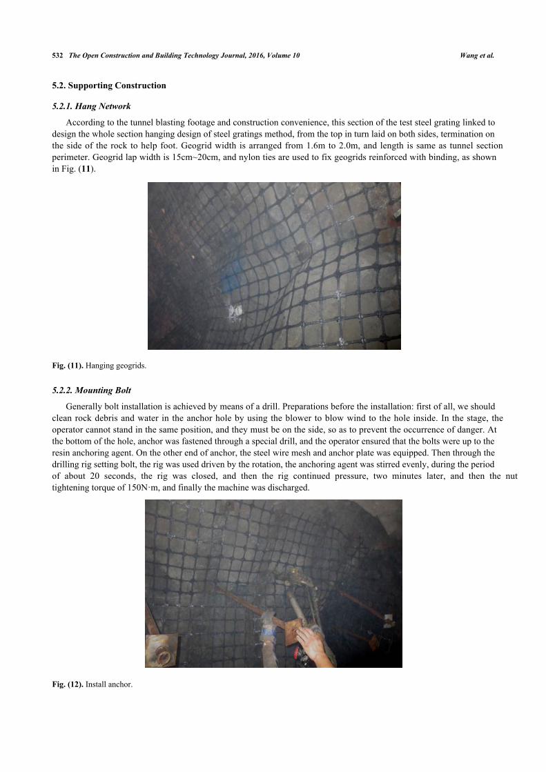
According to the tunnel blasting footage and construction convenience, this section of the test steel grating linked todesign the whole section hanging design of steel gratings method, from the top in turn laid on both sides, termination onthe side of the rock to help foot. Geogrid width is arranged from 1.6m to 2.0m, and length is same as tunnel sectionperimeter. Geogrid lap width is 15cm~20cm, and nylon ties are used to fix geogrids reinforced with binding, as shownin Fig. (11).
Fig. (11). Hanging geogrids.
5.2.2. Mounting Bolt
Generally bolt installation is achieved by means of a drill. Preparations before the installation: first of all, we shouldclean rock debris and water in the anchor hole by using the blower to blow wind to the hole inside. In the stage, theoperator cannot stand in the same position, and they must be on the side, so as to prevent the occurrence of danger. Atthe bottom of the hole, anchor was fastened through a special drill, and the operator ensured that the bolts were up to theresin anchoring agent. On the other end of anchor, the steel wire mesh and anchor plate was equipped. Then through thedrilling rig setting bolt, the rig was used driven by the rotation, the anchoring agent was stirred evenly, during the periodof about 20 seconds, the rig was closed, and then the rig continued pressure, two minutes later, and then the nuttightening torque of 150N·m, and finally the machine was discharged.
Fig. (12). Install anchor.
Experimental Study on Properties of Steel-plastic The Open Construction and Building Technology Journal, 2016, Volume 10 533
5.2.3. Jet Concrete
In the construction of secondary lining concrete, first of all, we should check whether the bolt hit and anchor Fig.(12) net meet the design objective, and give timely feedback and process to some existing problems. When theconditions are met, the secondary lining is poured. Pouring process is the same as the initial lining.
5.3. Analysis of Steel Grille Surrounding Rock Supporting Effect
For the scientific evaluation of the practical effect of the supporting scheme, the monitoring of the surrounding rockdeformation of the test section is needed. Among them, the deformation monitoring of surrounding rock is mainlythrough the test of different depth of rock mass deformation in support and reinforcement in order to understand theweakening and failure scope of surrounding rock.
5.3.1. Multi-point Displacement Monitoring of Roof
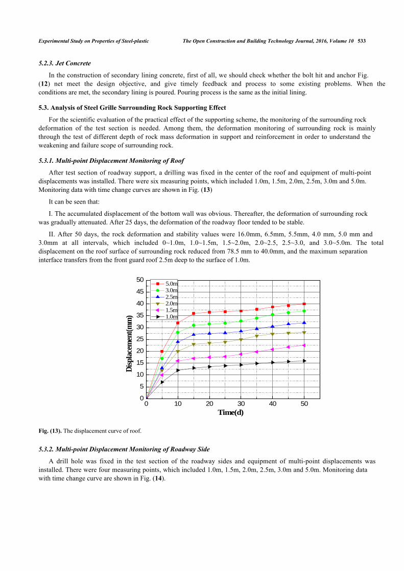
After test section of roadway support, a drilling was fixed in the center of the roof and equipment of multi-pointdisplacements was installed. There were six measuring points, which included 1.0m, 1.5m, 2.0m, 2.5m, 3.0m and 5.0m.Monitoring data with time change curves are shown in Fig. (13)
It can be seen that:
I. The accumulated displacement of the bottom wall was obvious. Thereafter, the deformation of surrounding rockwas gradually attenuated. After 25 days, the deformation of the roadway floor tended to be stable.
II. After 50 days, the rock deformation and stability values were 16.0mm, 6.5mm, 5.5mm, 4.0 mm, 5.0 mm and3.0mm at all intervals, which included 0~1.0m, 1.0~1.5m, 1.5~2.0m, 2.0~2.5, 2.5~3.0, and 3.0~5.0m. The totaldisplacement on the roof surface of surrounding rock reduced from 78.5 mm to 40.0mm, and the maximum separationinterface transfers from the front guard roof 2.5m deep to the surface of 1.0m.
Fig. (13). The displacement curve of roof.
5.3.2. Multi-point Displacement Monitoring of Roadway Side
A drill hole was fixed in the test section of the roadway sides and equipment of multi-point displacements wasinstalled. There were four measuring points, which included 1.0m, 1.5m, 2.0m, 2.5m, 3.0m and 5.0m. Monitoring datawith time change curve are shown in Fig. (14).
0 10 20 30 40 500
5
10
15
20
25
30
35
40
45
50
Disp
lacem
ent(m
m)
Time(d)
5.0m 3.0m 2.5m 2.0m 1.5m 1.0m
534 The Open Construction and Building Technology Journal, 2016, Volume 10 Wang et al.
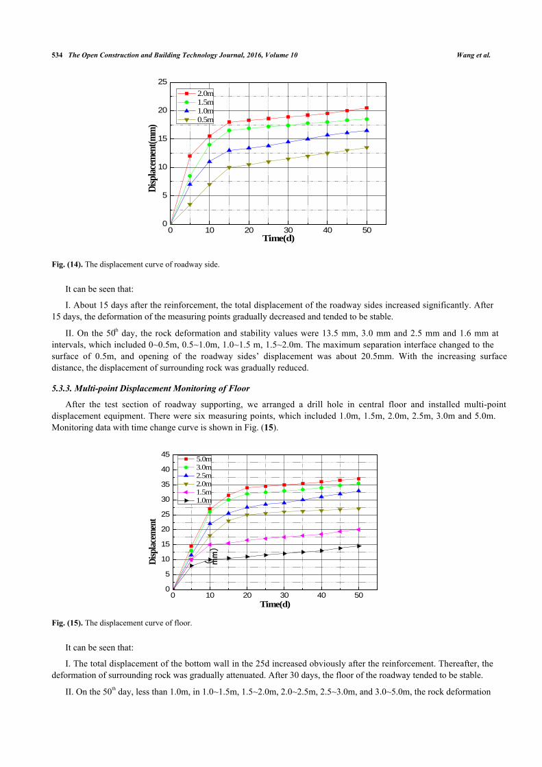
Fig. (14). The displacement curve of roadway side.
It can be seen that:
I. About 15 days after the reinforcement, the total displacement of the roadway sides increased significantly. After15 days, the deformation of the measuring points gradually decreased and tended to be stable.
II. On the 50th day, the rock deformation and stability values were 13.5 mm, 3.0 mm and 2.5 mm and 1.6 mm atintervals, which included 0~0.5m, 0.5~1.0m, 1.0~1.5 m, 1.5~2.0m. The maximum separation interface changed to thesurface of 0.5m, and opening of the roadway sides’ displacement was about 20.5mm. With the increasing surfacedistance, the displacement of surrounding rock was gradually reduced.
5.3.3. Multi-point Displacement Monitoring of Floor
After the test section of roadway supporting, we arranged a drill hole in central floor and installed multi-pointdisplacement equipment. There were six measuring points, which included 1.0m, 1.5m, 2.0m, 2.5m, 3.0m and 5.0m.Monitoring data with time change curve is shown in Fig. (15).
Fig. (15). The displacement curve of floor.
It can be seen that:
I. The total displacement of the bottom wall in the 25d increased obviously after the reinforcement. Thereafter, thedeformation of surrounding rock was gradually attenuated. After 30 days, the floor of the roadway tended to be stable.
II. On the 50th day, less than 1.0m, in 1.0~1.5m, 1.5~2.0m, 2.0~2.5m, 2.5~3.0m, and 3.0~5.0m, the rock deformation
0 10 20 30 40 500
5
10
15
20
25
Disp
lacem
ent(m
m)
Time(d)
2.0m 1.5m 1.0m 0.5m
0 10 20 30 40 500
5
10
15
20
25
30
35
40
45
Disp
lacem
ent
( mm)
Time(d)
5.0m 3.0m 2.5m 2.0m 1.5m 1.0m
Experimental Study on Properties of Steel-plastic The Open Construction and Building Technology Journal, 2016, Volume 10 535
and stability values were 14.5mm 5.5 mm and 7.0, 6.0mm and 2.5mm and 1.5mm. Maximum separation interface witha front protection plate deeply transferred to a surface of 1.0m.
The orifice of the surface of the base plate of the surrounding rock displacement was about 37.0mm. The distancefrom the surface of the bottom plate is gradually reduced, the deformation of the surrounding rock displacement whichwere less than 1.0 and 1.0~1.5m, accounting for 39.2% and 14.8% in total displacement. 1.5~2.0m, 2.0~2.5, 2.5~3.0m,3.0~5.0m rock deformation accounted for the total displacement capacity of 19.0%, 16.2%, 6.8% and 4.0%respectively.
5.4. Effect Evaluation
Through above mine supporting analysis in Hualian, the data showed that the deformation tended to be stable insupporting 25 days. After supporting 50 days, the maximum displacement of the roof was 40mm, maximumdisplacement of the side was 20.5mm, the maximum displacement of the floor was 37mm, and the maximumdeformation speed only was 0.8mm/d. The roadway is in a steady state, and the supporting effect was good.
CONCLUSION
Steel-plastic geogrid has better deformation resistant structure, twisted nodes and possesses roadway1.surrounding rock deformation settlement ability, high flexibility, high elasticity, nodes are not easy to be torn tosupport a multi direction load, and have a great effect on disperse loading,which has good tensile property, creepproperty and deflection performance.Steel-plastic geogrid and high-strength prestresses anchor combined support apply enough pre tightening force2.to the rock, improving the stress state of surrounding rock, controlling the deformation of surrounding rockeffectively, and reducing the cost of support. Steel-plastic geogrid plays an important role in roadwaysupporting.
CONFLICT OF INTEREST
The authors confirm that this article content has no conflict of interest.
ACKNOWLEDGEMENTS
This work was financially supported by:
(1) National Natural Science Foundation of China (NSFC) (41372289).
(2) SDUST Research Fund (2014TDJH103).
REFERENCES
[1] C.O. Aksoy, O. Zacar, and V. Kantarci, "An example for estimation of rock mass deformations around an underground opening by numericalmodeling", Int. J. Rock Mech. Min. Sci., vol. 47, pp. 272-280, 2010.[http://dx.doi.org/10.1016/j.ijrmms.2009.12.001]
[2] D. Zhao, G. Swoboda, and F. Laabmayr, "Damage mechanics and its application for the design of an underground theater", Tunn. Undergr.Space Technol., vol. 19, pp. 567-575, 2004.[http://dx.doi.org/10.1016/j.tust.2004.01.004]
[3] V. Hajiabdolmajid, P.K. Kaiser, and C.D. Martin, "Modelling brittle rock failure", Int. J. Rock Mech. Min. Sci., vol. 39, no. 6, pp. 731-141,2002.[http://dx.doi.org/10.1016/S1365-1609(02)00051-5]
[4] D.D. Tannant, "Load capacity and stiffness of welded wire, chain link and expanded metal mesh", In: Chapter 46 in Surface Support inMining., Melbourne: Australian Center for Geomechanics, 2004, pp. 387-390.
[5] D.D. Tannant, P.K. Kaiser, and S. Maloney, Load-displacement Properties of Welded-wire, Chain-link and Expand Metal Mesh InternationalSymposium on Rock Support., Norway, pp. 651-659, 1997.
[6] H. Witthaus, and N. Polysos, "Applied geomechanics for support design in German deep coal mines", In: Proceedings of the 25thInternational Conference on Ground Control in Mining [C]., West Virginia: Morgantown, 2006.
[7] W.F. Bawden, and J.D. Tod, "Optimization of cable bolt ground support using SMART instrumentation", ISRM News J., vol. 7, no. 3, pp.10-16, 2003.
536 The Open Construction and Building Technology Journal, 2016, Volume 10 Wang et al.
[8] B. Liu, Z.Q. Yue, and L.G. Tham, "Analytical design method for a truss-bolt system for reinforcement of fractured coal mine roofs-illustratedwith a case study", Int. J. Rock Mech. Min. Sci., vol. 42, no. 2, pp. 95-218, 2005.
[9] R.K. Brummer, and G.R. Swan, "Support and Structural Use of Shotcrete in Mines", In: W.A. Hustrulid and R.L. Bullock Ed., UndergroundMining Methods Engineering Fundamentals and International Case Studies, Society for Mining, Metallurgy and Exploration: Littleton,Colorad, 2001, pp. 593-600.
[10] B.J. Holmgren, "Shotcrete linings in hard rock", In: W.A. Hustrulid, and R.L. Bullock, Eds., Underground Mining Methods: EngineeringFundamentals and International Case Studies., Society for Mining, Metallurgy and Exploration: Littleton, Colorado, 2001, pp. 569-577.
[11] P.K. Kaiser, and D.D. Tannant, "The role of shotcrete in hard-rock mines", In: W.A. Hustrulid, and R.L. Bullock, Eds., Underground MiningMethods: Engineering Fundamentals and International Case Studies., Society for Mining, Metallurgy and Exploration: Littleton, Colorado,2001, pp. 579-592.
[12] S. Spearing, "Shotcrete as an underground support material", In: W.A. Hustrulid, and R.L. Bullock, Eds., Underground Mining Methods:Engineering Fundamentals and International Case Studies., Society for Mining, Metallurgy and Exploration: Littleton, Colorado, 2001, pp.563-568.
[13] E. Villaescusa, "An Australian perspective to grouting for cablebolt reinforcement", In: E. Villaescusa, C. R. Windsor, and A. G. Thompson,Eds., Proc. Int. Symp. Rock Support, Kalgoorlie, Balkema: Rotterdam, pp. 91-102, 1999.
[14] P.G. Fuller, "Roof strata reinforcement-achievements and challenges", In: E. Villaescusa, C. R. Windsor, and A. G. Thompson, Eds., Proc.Int. Symp. Rock Support, Kalgoorlie, Balkema: Rotterdam, pp. 405-415, 1999.
[15] L.I. Jian, and S.U. Zhiyong, "Laboratory studies on mechanical performance and supporting function of bolt metal meshes", J. China CoalSoc, vol. 38, no. 9, pp. 1542-1548, 2013.
[16] D.E. Xaolin, "Optimization and management of anchor mesh supporting technique for deep coal tunnel", Coal Mining Technol., vol. 10, no. 6,pp. 50-51, 2005.
[17] W.A. Qingbiao, "Steel plastic geogrid performance testing and its application in the reduction of spring back of shotcrete", The Open Const.Buil. Technol. J., vol. 9, no. 6, pp. 223-229, 2015.
[18] W.A. Qingbiao, "The research and development of safety forewarning composite integral strong geocell", Mat. Sci. J., vol. 9, pp. 139-145,2015.
[19] W.A. Qingbiao, "The mechanical property of bidirectional geogrid and its application research in retaining wall design", The Open Construct.Buil. Technol. J., vol. 9, pp. 214-222, 2015.
[20] W.A. Qingbiao, and L.Ü. Rongshan, "Experimental study of tensile properties of the steel-plastic geogrids", Mat. Sci. J., vol. 9, pp. 146-151,2015.
[21] S.U. Xiaoming, Y.A. Jun, and C.A. Wufu, "Research on space-time action rule of bolt-net-anchor coupling support for deep gateway",Chinese J. Rock Mech. Eng., vol. 26, no. 5, pp. 895-900, 2007.
[22] G.U. Junhui, C.H. Weiguo, and Z.H. Bin, "Research on creep property of geogrids at a low temperature", Rock Soil Mech., vol. 30, no. 10, pp.3009-3012, 2009.
[23] L.U. Maotian, X.I. Chengzhi, and Y.A. Qing, "An experimental study on the creep behavior of geogrids under long-term external loading",China Civil Eng. J., vol. 39, no. 4, pp. 87-91, 2006.
[24] X.L. Yang, and F. Huang, "Collapse mechanism of shallow tunnel based on nonlinear Hoek-Brown failure criterion", Tunn. Undergr. SpaceTechnol., vol. 26, pp. 686-691, 2011.[http://dx.doi.org/10.1016/j.tust.2011.05.008]
[26] F. Huang, and X.L. Yang, "Upper bound limit analysis of collapse shape for circular tunnel subjected to pore pressure based on the Hoek-Brown failure criterion", Tunn. Undergr. Space Technol., vol. 26, pp. 614-618, 2011.[http://dx.doi.org/10.1016/j.tust.2011.04.002]
[26] M. Fraldi, and F. Guarracino, "Analytical solutions for collapse mechanisms in tunnels with arbitrary cross sections", Int. J. Solids Struct., vol.47, no. 2, pp. 216-223, 2010.[http://dx.doi.org/10.1016/j.ijsolstr.2009.09.028]
[27] M.S. Diederichs, and P.K. Kaiser, "Stability of large excavations in laminated hard rock massesahe voussoir analogue revisited", Int. J. RockMech. Min. Sci., vol. 36, no. 1, pp. 97-117, 1999.[http://dx.doi.org/10.1016/S0148-9062(98)00180-6]
[28] M. Caia, P.K. Kaisers, Y. Tasakab, and M. Minamic, "Determination of residual strength parameters of jointed rock masses using the GSIsystem", Int. J. Rock Mech. Min. Sci., vol. 44, no. 2, pp. 247-265, 2007.[http://dx.doi.org/10.1016/j.ijrmms.2006.07.005]
[29] F. Varas, E. Alonso, and L.R. Alejano, "Study of bifurcation in problem of unloading a circular excavation in a strain-softening material",Tunn. Undergr. Space Technol., vol. 20, no. 5, pp. 311-322, 2005.[http://dx.doi.org/10.1016/j.tust.2004.12.003]
[30] K. Susantha, H. Ge, and T. Usami, "Uniaxial stress-strain relationship of concrete confined by various shaped steel tubes", Eng. Struct., vol.23, pp. 1331-1378, 2001.[http://dx.doi.org/10.1016/S0141-0296(01)00020-7]
Experimental Study on Properties of Steel-plastic The Open Construction and Building Technology Journal, 2016, Volume 10 537
[31] E. Inai, A. Mukai, M. Kai, H. Tokinoya, T. Fulcumoto, and K. Mori, "Behaviour of concrete-filled steel tube beam columns", J. Struct. Eng.,vol. 130, no. 2, pp. 189-202, 2004.[http://dx.doi.org/10.1061/(ASCE)0733-9445(2004)130:2(189)]
[33] T. Fujimoto, A. Mukai, I. Nishiyama, and K. Sakino, "Behavior of eccentrically loaded concrete-filled steel tubular columns", J. Struct. Eng.,vol. 130, no. 2, pp. 203-215, 2004.[http://dx.doi.org/10.1061/(ASCE)0733-9445(2004)130:2(203)]
[34] J.Y. Liew, T.H. Teo, and N.E. Shanmugam, "Composite joints subject to reversal of loading Part 1:Experimental study", J. Construct. SteelRes., vol. 130, no. 2, pp. 221-246, 2004.[http://dx.doi.org/10.1016/j.jcsr.2003.08.010]
[35] A.P. Gardner, and H.M. Goldsworthy, "Experimental investigation of the stiffness of critical components in a moment-resisting compositeconnection", J. Construct. Steel Res., no. 61, pp. 709-735, 2005.[http://dx.doi.org/10.1016/j.jcsr.2004.11.004]
[36] H.M. Goldsworthy, and A.P. Gardner, "Feasibility study for blind-bolted connections to concrete-filled circular steel tubular columns", Struct.Eng. Mech., no. 62, pp. 463-478, 2006.[http://dx.doi.org/10.12989/sem.2006.24.4.463]
[37] H.Y. Loh, B. Uy, and M.A. Bradford, "The effects of partial shear connection in composite flush end plate joints: Part I Experimental study",J. Construct. Steel Res., no. 62, pp. 378-390, 2006.[http://dx.doi.org/10.1016/j.jcsr.2005.07.012]
[38] H. Witthaus, N. Polysos, and H. Witthaus, "The effects of partial shear connection in composite flush end plate joints: Part I Experimentalstudy", J. Construct. Steel Res., vol. 62, pp. 378-390, 2006.
[39] W.F. Bawden, "Optimization of cable bolt ground support using SMART instrumentation", ISRM News J., vol. 7, no. 3, pp. 10-16, 2003.
[40] B. Liu, Z.Q. Yue, and L.G. Tham, "Analytical design method for a truss-bolt system for reinforcement of fractured coal mine roofs-illustratedwith a case study", Int. J. Rock Mech. Min. Sci., vol. 42, no. 2, pp. 195-218, 2005.[http://dx.doi.org/10.1016/j.ijrmms.2004.08.006]
[41] L.U. Mao-tian, X.I. Chengzhi, and Y.A. Qing, "Experimental study on creep properties and viscoelasticity constitutive relationship forgeogrids", Rock Soil Mech., vol. 26, no. 2, pp. 187-292, 2005.
[42] G.A. Shun-ping, "Research on the acting mechanism and application of metal net in bolt net support", J. North China Institute Sci. Technol.,vol. 1, no. 4, pp. 73-74, 2004.
[43] Z.H. Xingdong, and T.A. Chun’an, "Research on bolt-netting support under high stressed and fractured rockmass", Rock soil Mech., vol. 27,no. 2, pp. 918-920, 2006.
This is an open access article licensed under the terms of the Creative Commons Attribution-Non-Commercial 4.0 International Public License(CC BY-NC 4.0) (https://creativecommons.org/licenses/by-nc/4.0/legalcode), which permits unrestricted, non-commercial use, distribution andreproduction in any medium, provided the work is properly cited.