Send Orders of Reprints at [email protected]The Open Mechanical Engineering Journal, 2012, 6, 115-124 115 1874-155X /12 2012 Bentham Open Open Access Stress Analysis of an Endosseus Dental Implant by BEM and FEM R. Citarella *,1 , E. Armentani 2 , F. Caputo 3 and M. Lepore 1 1 Department of Industrial Engineering, University of Salerno, Italy 2 Department of Materials and Production Engineering, University of Naples Federico II, Italy 3 Department of Aerospace and Mechanical Engineering, Second University of Naples, Italy Abstract: In this work the Boundary Element Method (BEM) and the Finite Element Method (FEM) have been used for an elastic-static analysis of both a Branemark dental implant and a generic conic threaded implant, modelled either in the complete mandible or in a mandibular segment, under axial and lateral loading conditions. Two different hypotheses are considered with reference to degree of osteo-integration between the implant and the mandibular bone: perfect and partial osteointegration. The BEM analysis takes advantage of the submodelling technique, applied on the region surrounding the implant. Such region is extracted from the overall mandible and the boundary conditions for such submodel are obtained from the stress analysis realised on the complete mandible. The obtained results provide the localisation of the most stressed areas at the bone-implant interface and at the mandibular canal (containing the alveolar nerve) which represent the most critical areas during mastication. This methodology, enriched with the tools necessary for the numerical mandible reconstruction, is useful to realise sensitivity analysis of the stress field against a variation of the localisation, inclination and typology of the considered implant, in order to assess the optimal implant conditions for each patient under treatment. Due to the high flexibility in the pre- and post-processing phase and accuracy in reproducing superficial stress gradients, BEM is more efficient than FEM in facing this kind of problem, especially when a linear elastic constitutive material law is adopted. Keywords: Alveolar nerve, BEM, dental implant, FEM, human mandible, mandibular canal, submodelling technique. INTRODUCTION Dental implantology practice is still highly dependent on empirical factors related to the morphological and biological characteristics of the individual patient. This results in considerable inconveniences both to the operator, who is often obliged to choose solutions on short notice without any feedback from the implant design point of view, and to the patient, who sometimes undergoes unsuccessful attempts. Unfortunately, the extent of involved biological, morphological and mechanical parameters makes a reliable generalization of these applications difficult, if not impossible. The level of stresses and deformations in that part of the mandible bone surrounding the implant is critical for the implant stability [1]. In case of full osteointegration it is important for long term life and stability, whereas in case of partial osteointegration it is important in order to ensure an optimal transition towards a correct development of a full osteointegration. On the other hand, implant placement can cause an insult to the nervous structure and lead to transitory or irreversible *Address correspondence to these authors at the Department of Industrial Engineering, University of Salerno, Italy; Tel: +39089964111; Fax: +089964037; E-mail: [email protected]alterations of inferior nerve functionality [2]. Paraesthesia and disaesthesia following implant loading, due to compression on the nerve, have been reported [3]. To prevent this complication, a correct assessment of the mandibular canal position and a suitable choice of size and positioning of implant is needed [4, 5]. Studies have suggested the favourable positioning of a fixture with respect to adjacent natural teeth or, in more complex rehabilitations, the distance between fixtures to get an optimal distribution of occlusal forces and the best aesthetical result [6]. Several authors have also treated the problem of stress and strain assessment at the bone implant interface in order to scientifically address implantologist related decisions, in terms of implant positioning, inclination and sizes (diameter, length, profile...) [7-11]. In this work, elastic-static analyses are developed with specific reference to a Branemark implant and to a generic conic threaded implant undergoing axial and lateral forces [12, 13], using the finite element method (FEM) and the boundary element method (BEM). The obtained results revealed the localisation of the most stressed areas at the bone-implant interface and at the mandibular canal (containing the alveolar nerve). These are the most critical bone parts during mastication. Moving from continuity conditions at the implant-bone interface to slightly more complex numerical models,
Dental implantology practice is still highly dependent on empirical factors related to the morphological and biological characteristics of the individual patient. This results in considerable inconveniences both to the operator, who is often obliged to choose solutions on short notice without any feedback from the implant design point of view, and to the patient, who sometimes undergoes unsuccessful attempts.
Unfortunately, the extent of involved biological, morphological and mechanical parameters makes a reliable generalization of these applications difficult, if not impossible.
The level of stresses and deformations in that part of the mandible bone surrounding the implant is critical for the implant stability [1]. In case of full osteointegration it is important for long term life and stability, whereas in case of partial osteointegration it is important in order to ensure an optimal transition towards a correct development of a full osteointegration.
On the other hand, implant placement can cause an insult to the nervous structure and lead to transitory or irreversible
*Address correspondence to these authors at the Department of Industrial
Engineering, University of Salerno, Italy; Tel: +39089964111;
alterations of inferior nerve functionality [2]. Paraesthesia and disaesthesia following implant loading, due to compression on the nerve, have been reported [3]. To prevent this complication, a correct assessment of the mandibular canal position and a suitable choice of size and positioning of implant is needed [4, 5]. Studies have suggested the favourable positioning of a fixture with respect to adjacent natural teeth or, in more complex rehabilitations, the distance between fixtures to get an optimal distribution of occlusal forces and the best aesthetical result [6].
Several authors have also treated the problem of stress and strain assessment at the bone implant interface in order to scientifically address implantologist related decisions, in terms of implant positioning, inclination and sizes (diameter, length, profile...) [7-11].
In this work, elastic-static analyses are developed with specific reference to a Branemark implant and to a generic conic threaded implant undergoing axial and lateral forces [12, 13], using the finite element method (FEM) and the boundary element method (BEM).
The obtained results revealed the localisation of the most stressed areas at the bone-implant interface and at the mandibular canal (containing the alveolar nerve). These are the most critical bone parts during mastication.
Moving from continuity conditions at the implant-bone interface to slightly more complex numerical models,
116 The Open Mechanical Engineering Journal, 2012, Volume 6 Citarella et al.
namely with contact elements that simulate the clinical condition of partial rather than full osteointegration, substantial differences in bone structural behaviour become evident.
There is limited evidence with regards to the proper distance from implant to mandibular canal to assure the nerve integrity and physiological activity. This distance should be determined based not only on the evaluation of clinical data (retrospective study), but also on biomechanical analyses. A numerical mandibular model was therefore created to simulate a mandibular segment containing a couple of implants, so that the mechanical stresses on the mandibular canal induced by the occlusal load could be assessed.
The commercial codes used for FEM and BEM analyses are respectively ANSYS® and BEASY.
The accuracy of mandible stress distribution is enhanced by a realistic modelling of temporomandibular joints (one of the most critical areas after dental interventions) [14, 15], thus obtaining a higher precision in the boundary condition definition.
The resulting accuracy is evaluated by cross-comparisons between the two numerical methods (FEM and BEM) and with data available from literature.
One further objective of this work is to study the methodological problem concerning the selection of optimal numerical methods (between FEM and BEM) for this type of application.
PROBLEM DESCRIPTION AND NUMERICAL MODELS
In this work the implant is inserted in a mandibular segment or in the whole mandible; in the latter case the
temporo-mandibular joints are effectively modelled. The orthotropic properties of cortical and spongy bone are implemented in the model.
The forces exerted by the muscle bundles are evaluated by electromyography combined with the knowledge of muscle bundle sections and are applied in the areas of insertion of mandible muscles [14].
A partial or complete osteointegration is assumed at the bone-implant interface in order to consider different clinical conditions.
The bone material properties are calculated starting from data available from literature [14-17]. The value of bone-implant interface friction coefficient μ=0.42 is taken from reference [18].
The elastic-static analyses are performed with reference to a Branemark implant [19-21] or to a conic threaded implant [8], modelled as inserted in a mandible segment (Figs. 1a, b) or in the overall mandible (Figs. 2a, b) and subject to axial or lateral occlusion forces, arising from mastication.
The geometry of a Branemark implant made of titanium, with the modulus of elasticity equal to Ei=120 GPa and Poisson coefficient i=0.4, is shown in Fig. (1a). The thread of the implant body was not represented in its continuous helical characteristics but as axial-symmetric independent rings. On the contrary the modelling of the conic threaded implant, with a diameter d= 4.5 mm and a length l=11 mm, included the thread helix of the screw (Fig. 1b).
FEM and BEM Local Analysis with Branemark Implant
In a first approximation, useful to provide a benchmark between the two FEM and BEM methodologies and to compare results of both with literature data [19-21], the
Fig. (1). Geometry of the Branemark implant (a) and of a conic threaded implant (b).
�
���
���
��
�
��
�� ��
�
�
�
�
Stress Analysis of an Endosseus Dental Implant by BEM and FEM The Open Mechanical Engineering Journal, 2012, Volume 6 117
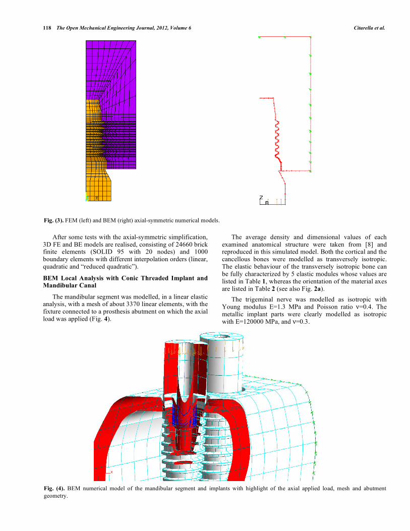
implant is inserted in a mandibular segment that is clamped on the lateral surfaces, without allowance for the overall mandible and related boundary conditions (Fig. 3). Two loading conditions are considered: an axial resultant load, equal to 100 N, applied on the abutment by means of a uniform pressure distribution and a lateral resultant load, equal to 75 N, applied by a uniform distribution of internal forces along the abutment axis (Fig. 3).
When considering the vertical load condition, the problem is modelled as axial-symmetric, with isotropic mechanical properties for the bone (Eo=16 GPa and o=0.3).
The FEM and BEM axial-symmetric models, undergoing vertical load, are discretized by 1370 elements (SOLID 82, eight-node axial-symmetric) and 86 quadratic elements (Fig. 3).
When modelling the lack of osteo-integration at the interface between implant and bone, unidirectional contact elements (of GAP type) are introduced in both FEM and BEM approaches. Such GAP elements also allow the modelling of friction conditions between the surfaces in contact.
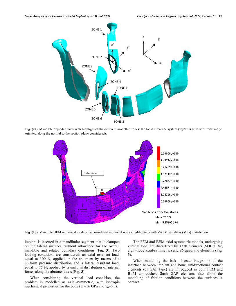
Fig. (2a). Mandible exploded view with highlight of the different modelled zones: the local reference system (x’y’z’ is built with z’//z and y’
oriented along the normal to the section plane considered).
Fig. (2b). Mandible BEM numerical model (the considered submodel is also highlighted) with Von Mises stress (MPa) distribution.
x
z
ZONE 1
ZONE 2
ZONE 3
ZONE 4
ZONE 5
ZONE 6
ZONE 7
ZONE 8
y’
x’
z’
y
x
z
Sub-model
118 The Open Mechanical Engineering Journal, 2012, Volume 6 Citarella et al.
After some tests with the axial-symmetric simplification, 3D FE and BE models are realised, consisting of 24660 brick finite elements (SOLID 95 with 20 nodes) and 1000 boundary elements with different interpolation orders (linear, quadratic and “reduced quadratic”).
BEM Local Analysis with Conic Threaded Implant and Mandibular Canal
The mandibular segment was modelled, in a linear elastic analysis, with a mesh of about 3370 linear elements, with the fixture connected to a prosthesis abutment on which the axial load was applied (Fig. 4).
The average density and dimensional values of each examined anatomical structure were taken from [8] and reproduced in this simulated model. Both the cortical and the cancellous bones were modelled as transversely isotropic. The elastic behaviour of the transversely isotropic bone can be fully characterized by 5 elastic modules whose values are listed in Table 1, whereas the orientation of the material axes are listed in Table 2 (see also Fig. 2a).
The trigeminal nerve was modelled as isotropic with Young modulus E=1.3 MPa and Poisson ratio =0.4. The metallic implant parts were clearly modelled as isotropic with E=120000 MPa, and =0.3.
Fig. (3). FEM (left) and BEM (right) axial-symmetric numerical models.
Fig. (4). BEM numerical model of the mandibular segment and implants with highlight of the axial applied load, mesh and abutment
geometry.
Stress Analysis of an Endosseus Dental Implant by BEM and FEM The Open Mechanical Engineering Journal, 2012, Volume 6 119
Table 1. Material Properties Under Transversal Isotropic
Material Behaviour (x’z’ is the Isotropic Plane)
Average Density Bone
Canal Spongy Bone Cortical Bone
Ex’ (MPa) 2.03E+03 7.19E+02 1.22E+04
Ey’ (MPa) 3.20E+03 1.14E+03 1.93E+04
Gx’y’ (MPa) 7.24E+02 2.55E+02 4.37E+03
y’x’ 0.364 0.368 0.366
x’z’ 0.341 0.342 0.345
Table 2. Orientation of the Material Reference System x’y’z’
in the Global Reference System xyz (z//z’)
Area 1 2 3 4 5 6 7 8
qx’x (degree) -28 -28 -28 -28 -59 -59 -90 -90
To calculate the pressure on the nerve, a nonlinear BEM contact analysis was performed, with a null clearance imposed between the nerve and the surrounding canal structures (this is the worst case because generally a minimum clearance is available between the nerve and the canal).
The applied load was equal to 300 N along the implant axis, corresponding to 150 N on each implant (Fig. 4); all the simulations considered a canal that is orthogonal to the implant axis.
The pressure distribution induced on the underlying nervous structure, was evaluated considering a distance of d=1.0 mm from the fixture to the mandibular canal.
BEM Analysis on the Overall Mandible and Submodelling
In order to reduce the computational time and memory requirements, when considering the whole mandible, the submodelling technique is adopted: the mandible part surrounding the implant has been extracted from the overall model and the displacements, calculated from the global analysis on the whole mandible (Fig. 2b), have been applied on the cutting surfaces (Fig. 5).
When considering the whole mandible model, including temporo-mandibular joints [14, 15], the real implant is replaced by a non threaded cylinder with the same external size (Fig. 6), in order to reduce the computational burden. The effects of such approximations on the cutting surfaces are negligible. Traction and displacements continuity conditions are imposed between cylindrical surface and implant bone.
ANALYSIS RESULTS
FEM and BEM Local Analyses (Isotropic Bone
Properties with No Allowance for the Whole Mandible)
With reference to the axial load case, Von Mises stress distributions in the bone undergoing axial masticatory load are shown in Fig. (7), and are calculated by means of BEM
and FEM codes respectively. The fillet radius is equal to 0.15 mm immediately under the first thread and 0.3 mm further down (Fig. 7).
Fig. (5). Submodel with imposed displacement boundary conditions
and contour plot of Von Mises stresses (MPa).
Fig. (6). Branemark implant embedded in the submodel (left) and
related approximate shape when considering the global analysis on
the overall model (right).
With the introduction of bone-implant interface contact elements, and disregarding friction, the distribution of BEM and FEM Von Mises equivalent stresses varies significantly with a strong increase in the maximum values (Fig. 8).
The analysis with friction between implant and bone is carried out with a friction coefficient μ=0.42. The BEM and FEM analysis results are shown in Fig. (9), with lower stress peaks in comparison to the previous frictionless case.
The axial load case, with bone-implant interface continuity, is also developed with a 3D modelling approach in order to make a cross comparison with the results obtained by axial-symmetric modelling. The BEM and FEM Von Mises stress distributions are shown in Fig. (10a, b)
120 The Open Mechanical Engineering Journal, 2012, Volume 6 Citarella et al.
respectively and correspond to those shown in Fig. (7). The lateral load case is then considered (Fig. 11) and in this case the three-dimensional approach is mandatory.
The satisfactory correspondence between FEM and BEM bone stress distribution is apparent from the previous figures and it is clear that these results are also in good agreement with those available from literature [19-21].
BEM Local Analysis with Conic Threaded Implant and Mandibular Canal
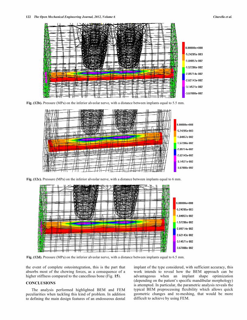
In Fig. (12a-d), the BEM contour plot shows the pressure on the nervous structure for a varying distance between the fixtures in case of axial load.
These results showed the sensitivity of nerve pressure against variations of distance between implants, considering
Fig. (10a). Von Mises stresses in the bone (MPa), under axial load,
by BEM three-dimensional modelling.
Fig. (7). BEM (left) and FEM (right) Von Mises equivalent stress (MPa) with close-up of the most stressed area.
Fig. (8). BEM (left) and FEM (right) Von Mises equivalent stress (MPa) with contact elements at the bone-implant interface.
Fig. (9). BEM (left) and FEM (right) Von Mises equivalent stresses (MPa) with contact elements at the bone-implant interface, in case of
friction with coefficient μ = 0.42.
r=0.3
r=0.15
Stress Analysis of an Endosseus Dental Implant by BEM and FEM The Open Mechanical Engineering Journal, 2012, Volume 6 121
a distance between implant bottom and canal (upper part) equal to 1 mm. As expected, the nerve pressure increased as implant distance decreased.
BEM Analysis on the Overall Mandible and Related Submodelling
Linear elastic BEM analyses for both the mandible model and submodel were developed using a mixed mesh of linear and quadratic elements. The former with 5534 elements and the latter with 1905 elements.
The coincidence between the resultant reaction force (equal to nearly 100 N)¸ provided by the constraints in the z direction applied on the abutment (Fig. 2b) and calculated in
both the global analysis and in the local submodel analysis, represents a first verification of the accuracy of the submodelling technique.
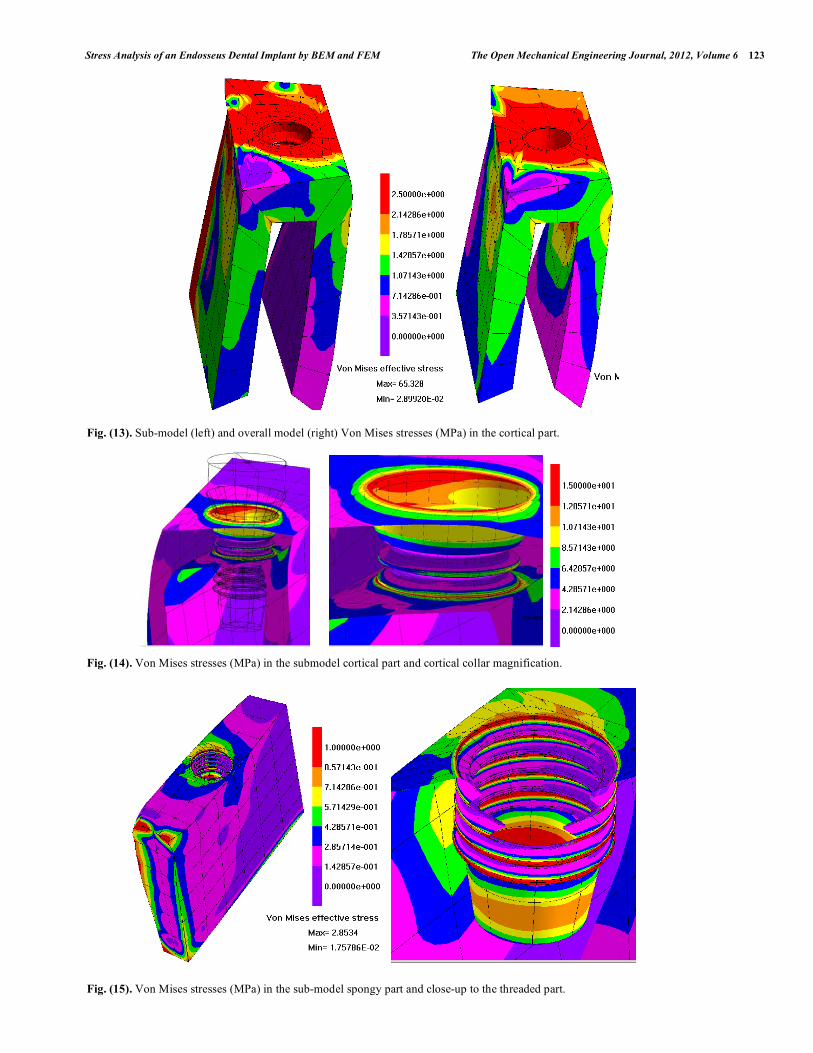
A further confirmation is provided by the comparison between the Von Mises stresses on the submodel boundaries as calculated from the global analysis and from the submodel analysis. Their agreement, far from the threaded part is evident from Fig. (13).
Particularly significant is the stress concentration at the implant-bone interface, due to the implant specific geometrical profile and loading conditions. It is observed that, with reference to the cortical bone, Fig. (14), the most loaded part is the collar surrounding the implant. In fact, in
Fig. (10b). Von Mises stresses in the bone (MPa), under axial load, by FEM three-dimensional modelling.
Fig. (11). BEM (left) and FEM (right) Von Mises equivalent stress (MPa) under lateral load.
Fig. (12a). Pressure (MPa) on the inferior alveolar nerve, with a distance between implants equal to 5 mm.
122 The Open Mechanical Engineering Journal, 2012, Volume 6 Citarella et al.
the event of complete osteointegration, this is the part that absorbs most of the chewing forces, as a consequence of a higher stiffness compared to the cancellous bone (Fig. 15).
CONCLUSIONS
The analysis performed highlighted BEM and FEM peculiarities when tackling this kind of problem. In addition to defining the main design features of an endosseous dental
implant of the type considered, with sufficient accuracy, this work intends to reveal how the BEM approach can be advantageous when an implant shape optimization (depending on the patient’s specific mandibular morphology) is attempted. In particular, the parametric analysis reveals the typical BEM preprocessing flexibility which allows quick geometric changes and re-meshing, that would be more difficult to achieve by using FEM.
Fig. (12b). Pressure (MPa) on the inferior alveolar nerve, with a distance between implants equal to 5.5 mm.
Fig. (12c). Pressure (MPa) on the inferior alveolar nerve, with a distance between implants equal to 6 mm.
Fig. (12d). Pressure (MPa) on the inferior alveolar nerve, with a distance between implants equal to 6.5 mm.
Stress Analysis of an Endosseus Dental Implant by BEM and FEM The Open Mechanical Engineering Journal, 2012, Volume 6 123
Fig. (13). Sub-model (left) and overall model (right) Von Mises stresses (MPa) in the cortical part.
Fig. (14). Von Mises stresses (MPa) in the submodel cortical part and cortical collar magnification.
Fig. (15). Von Mises stresses (MPa) in the sub-model spongy part and close-up to the threaded part.
124 The Open Mechanical Engineering Journal, 2012, Volume 6 Citarella et al.
Finally, working with 3D models, the mesh refinement in the neighbouring areas where high stress gradients are expected is much more flexible when using BEM, rather than FEM also because it is possible to use discontinuous elements.
Future perspectives of this kind of simulation will require to cope with mechano-biological aspects [22]. Shape and elasticity of bone change over time (bone remodelling) and consequently the equations have to be related to the rate of change of bone geometry (internal shape and porosity) with time, depending on a mechanical stimulus (such as strain energy density or damage).
CONFLICT OF INTEREST
The authors confirm that this article content has no conflicts of interest.
ACKNOWLEDGEMENTS
Declared none.
REFERENCES
[1] E. Kitamura, R. Stegaroiu, S. Nomura, O. Miyakawa, “Biomechanical
aspects of marginal bone resorption around osteointegrated implants: considerations based on a three –dimensional finite element analysis”,
Clinical Oral Implants Research, vol. 15, no. 4, pp. 401-412, 2004. [2] D. Wismeijer, M.A.J. van Waas, W.K. Vermeeren, “Patient’s
perception of sensory disturbances of the mental nerve before and after implant surgery: a prospective study of 110 patients”, British
Journal of Oral and Maxillofacial Surgery, vol. 35, pp. 254-259, 1997.
[3] D.S. Levitt, “Apicoectomy of an endosseous implant to relieve paresthesia: a case report”, Implant Dentistry, vol. 12, no. 3, pp. 202-
205, 2003. [4] G. Greenstein, D. Tarnow, “The mental foramen and nerve:
Clinical and anatomical factors related to dental implant placement: a literature review”, Journal of Periodontology, vol. 20, pp. 1933-
1943, 2006. [5] G. Santler, H. Karcher, C. Ruda, “Indications and limitations of
three-dimensional models in cranio-maxillofacial surgery”, Journal of Cranio-Maxillofacial Surgery, vol. 26, pp. 11-16, 1998.
[6] J.C. Kois, “Predictable single tooth peri-implant aesthetics: five diagnostic keys”, Compendium of Continuing Education in
Dentistry, vol. 22, pp. 199-206, 2001. [7] B. Bono, A. Cirello. D. Geraci, A. Pasta, A. Cassaro, “FEM model
achievement for dental implant characterization”, European Journal of Implant Prosthodontics, vol. 2, pp. 75-85, 2005.
[8] G. Sammartino, G. Marenzi, R. Citarella, R. Ciccarelli, H.-L. Wang, “Analysis of the occlusal stress transmitted to the inferior
alveolar nerve by an osseointegrated threaded implant”, Journal of
Periodontology, vol. 79, no. 9, pp. 1735-1744, 2008. [9] M. Cehreli, J. Duyck, M. De Cooman, R. Puers, I. Naert, “Implant
design and interface force transfer”, Clinical Oral Implants Research, vol. 15, no. 2, pp. 249-257, 2004.
[10] P. Franciosa, M. Martorelli, “Stress-based performance comparison of dental implants by finite element analysis”, International
Journal on Interactive Design and Manufacturing, vol. 6, No. 2, 2012, pp. 123-129.
[11] P. Ausiello, P. Franciosa, M. Martorelli, D.C. Watts, “Effects of thread features in osseo-integrated titanium implants using a
statistics-based finite element method”, Dental Materials, vol. 28, no. 8, 2012, pp. 919-927.
[12] C.H. Gibbs, P.E. Mahan, H.C. Lundeen, “Occlusal forces during chewing and swallowing as measured by sound transmission”,
Journal of Prosthetic Dentistry, vol. 46, pp. 443-449, 1982. [13] J.H. Koolstra, T.M. van Eijden, W.A. Weijs, M. Naeije, “A three
dimensional mathematical model of the human masticatory system predicting maximum possible bite forces”, Journal of
Biomechanics, vol. 21, pp. 573-576, 1988. [14] E. Armentani, F. Caputo, R. Citarella, “FEM sensitivity analyses
on the stress levels in a human mandible with a varying ATM modelling complexity”, The Open Mechanical Engineering
Journal, vol. 4, pp. 8-15, 2010. [15] R. Citarella, E. Armentani, F. Caputo, A. Naddeo, “FEM and BEM
analysis of a human mandible with added temporomandibular joints”, The Open Mechanical Engineering Journal, vol. 6, pp.
This is an open access article licensed under the terms of the Creative Commons Attribution Non-Commercial License (http://creativecommons.org/licenses/by-nc/3.0/)
which permits unrestricted, non-commercial use, distribution and reproduction in any medium, provided the work is properly cited.