I I I I I I I i ! I I I i ! 1 I * i I I I SERVICE INFORMATION FROM HEWLETT-PACKARD 1 st Quarter 1993 The Optical Spectrum Analyzer Richard OgglHewlett-Packard Introduction The optical spectrum analyzer (or OSA) is a very common piece of test equipment on the lightwave bench. These instruments were first intro- duced about 10 years ago. HP's basic OSA product is the HP 71450A, which operates in the 600 to 1700 nm range. Standard hardware options include Option 001, which adds a program- mable current source and Option 009 for 9 Fm input fiber. Modulation The Optical Spectrum Analyzer vs. the Lightwave Signal Analyzer What is the difference between an op- tical spectrum analyzer and a light- wave signal analyzer that measures modulation on optical signals? First, let's talk about how the OSA works. The Optical SpectrumAnalyzer A very simple diagram (see Figure 1) illustrates the basic concept through the familiar prism. Light passes through a prism where it is split, being distributed according to its wavelength. Next, a variable-width slit is used to select only the wavelength desired, which is focused on a photodetector. This allows the OSA to measure optical power levels versus wavelength. f Pub. NO. 5952-3463 In reality, prisms are too inefficient. To reduce the space required by a prism, a grating is used. The effect of the grating is the same as the prism, except the spreading happens much faster and the light is now reflected in the other direction. The variable slit and photodetector are still used. The Lightwave Signal Analyzer The lightwave signal analyzers intro- duced several years ago are based on a broad-band photodetector used to demodulate an optical signal. The output of the photodetector is coupled to a preamplifier. This amplified signal is then routed to a microwave spectrum analyzer. The result is the ability to measure baseband modulation information on the optical signal, but without any in- formation about the wavelength of the optical signal. OSA Wavelength Measurements Again, the OSA is used to show power levels as a function of wavelength. (This is just like micro- wave spectrum analyzers, which show power versus frequency.) Recall that frequency and wavelength are in- verse relations. The OSA sweeps in- creasing wavelength, which is de- (See "Optical Spectrum Analyzer," page 4) Figure 1. Basic Concept of Optical Spectrum Analyzer 0 Hewlett-Packard 1993 WWW.HPARCHIVE.COM
Transcript
I
I
I
I I I
I i
! I I
I
i
!
1 I
*
i I
I
I
SERVICE INFORMATION FROM HEWLETT-PACKARD 1 st Quarter 1993
The Optical Spectrum Analyzer Richard OgglHewlett-Packard
Introduction
The optical spectrum analyzer (or OSA) is a very common piece of test equipment on the lightwave bench. These instruments were first intro- duced about 10 years ago. HP's basic OSA product is the HP 71450A, which operates in the 600 to 1700 nm range. Standard hardware options include Option 001, which adds a program- mable current source and Option 009 for 9 Fm input fiber.
Modulation The Optical Spectrum Analyzer vs. the Lightwave Signal Analyzer What is the difference between an op- tical spectrum analyzer and a light- wave signal analyzer that measures modulation on optical signals? First, let's talk about how the OSA works.
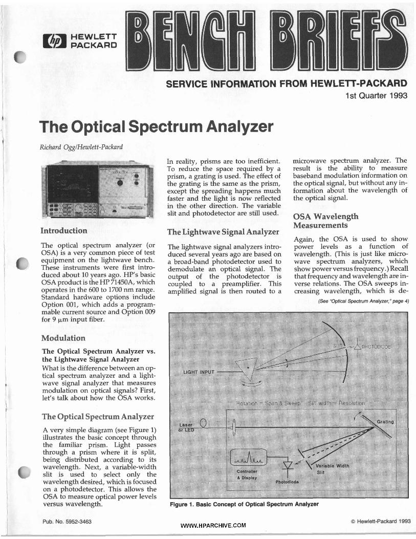
The Optical Spectrum Analyzer A very simple diagram (see Figure 1) illustrates the basic concept through the familiar prism. Light passes through a prism where it is split, being distributed according to its wavelength. Next, a variable-width slit is used to select only the wavelength desired, which is focused on a photodetector. This allows the OSA to measure optical power levels versus wavelength.
f
Pub. NO. 5952-3463
In reality, prisms are too inefficient. To reduce the space required by a prism, a grating is used. The effect of the grating is the same as the prism, except the spreading happens much faster and the light is now reflected in the other direction. The variable slit and photodetector are still used.
The Lightwave Signal Analyzer
The lightwave signal analyzers intro- duced several years ago are based on a broad-band photodetector used to demodulate an optical signal. The output of the photodetector is coupled to a preamplifier. This amplified signal is then routed to a
microwave spectrum analyzer. The result is the ability to measure baseband modulation information on the optical signal, but without any in- formation about the wavelength of the optical signal.
OSA Wavelength Measurements Again, the OSA is used to show power levels as a function of wavelength. (This is just like micro- wave spectrum analyzers, which show power versus frequency.) Recall that frequency and wavelength are in- verse relations. The OSA sweeps in- creasing wavelength, which is de-
(See "Optical Spectrum Analyzer," page 4)
Figure 1. Basic Concept of Optical Spectrum Analyzer
0 Hewlett-Packard 1993 WWW.HPARCHIVE.COM
Microwave Measurements
1992-1 993 Microwave Test Accessories Catalog Introduction
Hewlett-Packard offers a complete line of microwave measurement equipment for testing and charac- terizing components and systems from dc to 110 GHz. A test setup can be assembled from HI' instruments and measurement accessories de- scribed in this catalog.
From a functional standpoint, HI' di- vides microwave measurements into the following categories:
rn Impedance Measurements w Attenuation Measurements rn Power Measurements rn Noise Figure Measurements
Spectrum Analysis rn Calibration and Metrology Mea-
surements
Impedance and Attenuation Measurements - Types of Analyzers
Scalar Network Analyzers This measurement technique uses the amplitude-only information available from detectors and directional bridges. Analysis is performed using frequency-swept displays in the bandwidth of interest and results are quickly displayed on a graphics screen or transferred to a plotter. Sca- lar measurements are most common in production environments.
Power Meters Power meters use only the amplitude information available from power sensors through splitters or couplers at individual frequencies. Power sen- sors work over a wide frequency range and are provided with a refer- ence signal from the power meter. Measurements are more accurate and slower than scalar analyzers, and are usually performed in production and standard environments.
Vector Network Analyzers These analyzers provide the most ac- curate measurements available over a wide range of discrete frequencies. Computational power is provided
through convenient computer inter- face and measurements can be easily reconfigured. Calibration standards traceable through NIST provide the lowest measurement uncertainties and years of reliable service.
Vector Voltmeters This solution provides the most economical measurement technique up to 2 GHz for individual frequen- cies, and is used with splitters, test sets, and couplers.
Equipment Selection HI' equipment capability ranges from inexpensive test systems assembled from directional couplers to powerful analyzers that furnish dynamic dis- plays of error-corrected vector mea- surements. Equipment selection and measuring technique depend on the accuracy, speed, and cost require- ments of the application. Some appli- cations require complete characteriza- tion of microwave components. Vec- tor measurements are usually made in development labs to aid compo- nent design and characterization. The bulk of microwave testing is per- formed in production test, installa- tion, and maintenance, which is ac- complished with scalar systems. These systems are easy-to-use, low- cost, and easy for operators to under- stand.
Discussion of Uncertainties Scalar Network Analyzers Common uncertainties include detec- tor and analyzer linearities, which are usually small; directivity of direc- tional couplers and bridges; and mis- match errors between the various components of the system. The mag- nitude of the error is obtained by simple tracking and directivity mea- surements using the recommended .calibration and verification kits.
Power Meters Uncertainties arise in this technique from the directivity of the couplers, linearity of the power meter and sen- sor, and mismatch errors between the sensors and the devices to be tested. Computer controlled systems aid the user with the determination of the er- rors present.
Vector Network Analyzers Because these analyzers obtain both phase and amplitude information, uncertainties are very small and can be determined from physical mea- surements of the standards used or by the use of recommended verifica- tion kits. This system is the most com- mon type found in metrology applica- tions.
Vector Voltmeters Uncertainties can occur from the meter linearities and mismatches be- tween various components of the measurement system. These can also be estimated by knowing the values of the individual components.
Reflectometer Calculator The HP Reflectometer Calculator (Lit- erature No. 5952-0948) is invaluable for estimating the uncertainties in most systems. For example, measur- ing a 20 dB fixed attenuator that has a SWR of 1.5 with a power sensor that has a SWR of 1.4 could yield an uncer- tainty of about ? 0.3 dB. Similarly, measuring a termination with a return loss of 20 dB on a system with 40 dB of directivity could yield an uncer- tainty of about 0.9 dB. Both calcula- tions are very quick on the Reflec- tometer Calculator.
Copies of the 1992-1993 Microwave Test Accessories Catalog can be ob- tained through your local HP sales/ service office. Order publication number 5091-4269E. 0
2 BENCH BRIEFS WWW.HPARCHIVE.COM 1ST QUARTER 1993
Hewlett-Packard Announces Service Parts Bulletin Board Automated Telefax Blythe MasonlHewlett-Packard
HP Customers can now obtain cur- rent lists of HP service parts, high- volume supplies and accessories, and documentation for HP personal com- puters, peripherals, and Test and Measurement products in two ways. One way is through HP FIRST and the other is through HP Service PartsIDs Bulletin Board Service (BBS). Both methods are available 24 hours a day, seven days a week, and both provide accurate, detailed part descriptions, pricing information, and recommended stocking levels.
HP FIRST
HP FIRST (HP's automated fax re- trieval service) is available by calling 1-800-333-1917. A Voice Response Unit (VRU) directs customers to an index of all available parts lists. To request a particular list, customers enter the appropriate document refer- ence number and the telephone number of the destination fax machine - then hang up. Within mi- nutes, the information is transmitted to the fax machine selected.
'
Service and
HP Service PartsID Bulletin Board Service (BBS)
Customers with access to a personal computer and modem can request electronic files of any of the lists found on HP FIRST by calling our new HP Service PartsID BBS at 1-800-635- PART (7278). Once you are connected to HP's computer, the dialog will help you configure your personal com- puter to the right settings. Before you dial you may want to set your PC to the following basic settings:
This new service will allow customers to view parts lists on-line, download any or all of the parts lists in an ASCII format for use with resident applica- tions, and interact with an HP service parts database that can help custom- ers quickly locate specific parts.
Another feature of the BBS is its elec- tronic mail capability, which allows
customers to send inquiries to a dedi- cated system operator. Customers re- ceive answers to their questions in 48 hours or less.
Update Schedule
At the beginning of every month, all HP service parts lists are updated to reflect price changes, part number ad- ditions or deletions, and recently in- troduced products. Customers should plan to call early each month to receive the latest HP service parts information.
For more information on either HP FIRST or HP Service PartsIDs BBS, contact Randy Wagner at (916) 785-3257. 0
1'1 - n * _ P I T ' 1993
f
1ST QUARTER 1993
Logistics Data Book
- John Cloutier/Haulett-Packard
If your work requires U.S. Govern- ment National Stock Numbers (NSNs) for HP products and their components, HP's annual Logistic Data Book and its companion micro- fiche are must-have resources.
The data book cross references HP product numbers to National Stock Numbers (NSNs) and Joint Electronic Type Designators (JETDs), lists con-
WWW.HPARCHIVE.COM
tract numbers for provisioned prod- ucts, and rcommends replacements for discontinued products. The com- panion microfiche lists NSNs for product components and can be re- quested with postage-paid cards in- cluded in the data books.
To obtain a free copy of the 1993 Logistics Data Book, contact your nearest HP office, or:
John Cloutier Hewlett-Packard Company Federal Support Services MS 51U-TH P.O. Box 58059 Santa Clara, CA 95052-8059 0
BENCH BRIEFS 3
(‘Optical Spectrum Analyzer,” continued from page 1 )
creasing frequency. (Yes, one could say that “it sweeps backwards,” but we do not use that term.) The range of the OSA is 600 nm to 1700 nm. As a comparison, the visible wavelength range is approximately 300 nm to 650 nm (but varies somewhat from indi- vidual to individual). It is interesting to note that in lightwave, longer wavelength corresponds to higher performance. So sweeping from short wavelength to long wavelength is analogous with pushing to higher and higher microwave frequencies.
OSA Resolution
But if the OSA is conceptually much like a conventional spectrum analyzer, why is it not used to see modulation? It could be, depending on the relative bandwidths involved. The OSA has ”resolutions” (like resol- ution bandwidths) from 0.08 nm to 10 nm. A common wavelength for op- tical work is 1300 nm, which is about 230 THz. At this wavelength, a resol- ution of 0.1 nm is about 18 GHz. So, modulation can be easily seen if its bandwidth is considerably wider than 18 GHz. Optical modulators that have a bandwidth this wide are not yet commonly found. Most RF modula- tion of a laser is only a few GHz in bandwidth, so all the modulation in- formation falls within the resolution of the OSA. It is like trying to look at 1 kHz sidebands in a 1 MHz resolution bandwidth. Therefore, the OSA does not replace the LSA; you need both.
OSA Measurements
So what measurements are made with an OSA? Certainly it can be used to see at what wavelength(s) an optical device is emitting. It also shows what the relative power levels or power widths are. This is valuable for white light sources or infrared LEDs. The OSA can show the bandwidth if the device is broadband, or show what wavelengths are present.
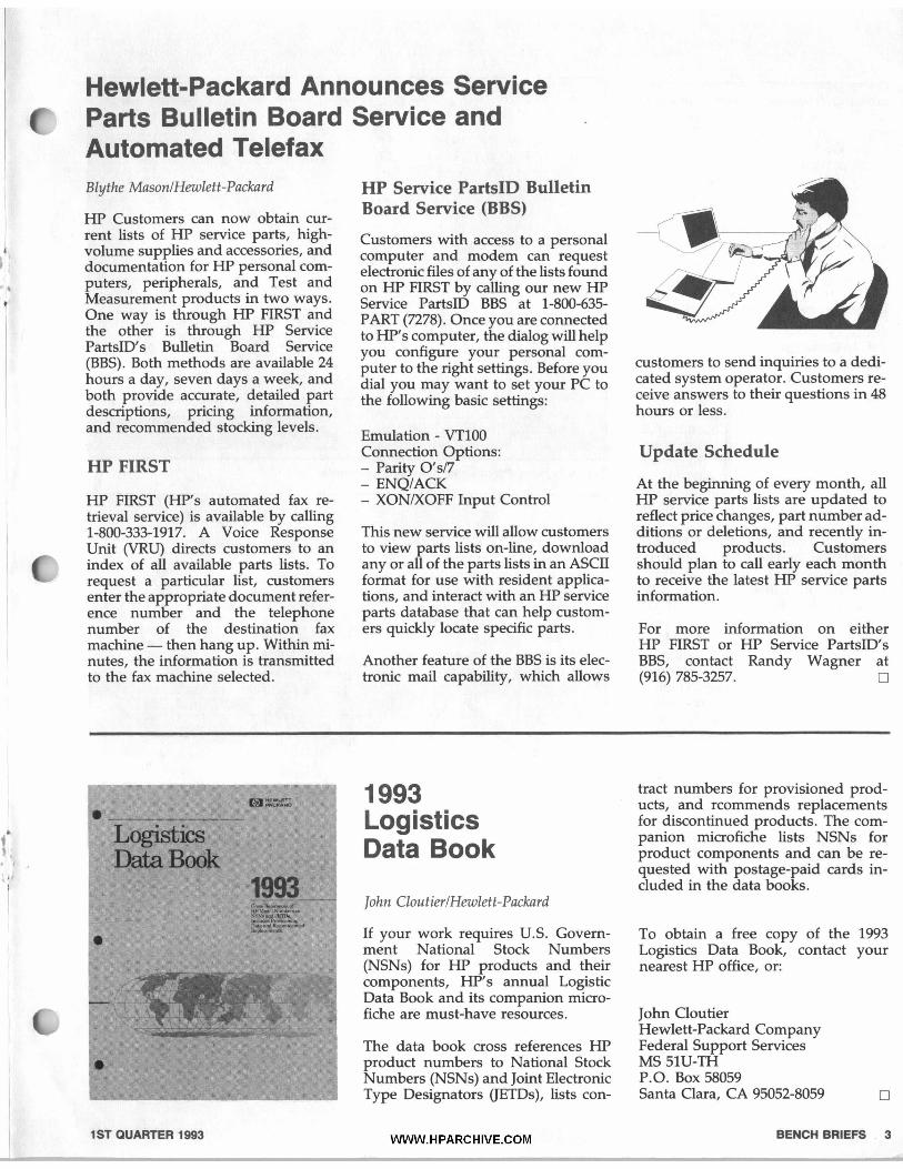
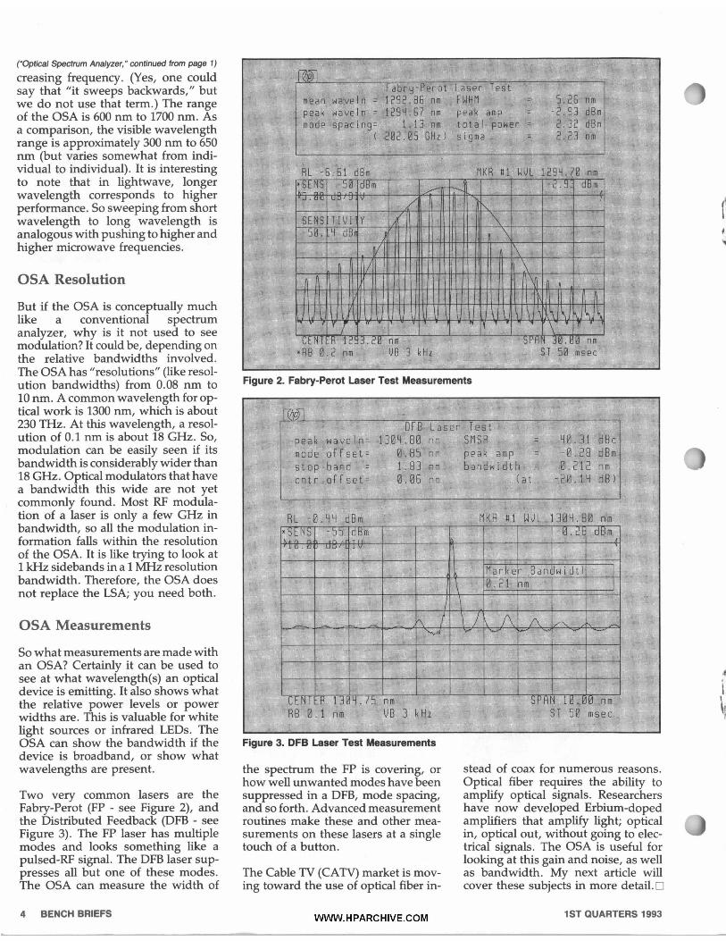
Two very common lasers are the Fabry-Perot (FP - see Figure 2), and the Distributed Feedback (DFB - see Figure 3). The FP laser has multiple modes and looks something like a pulsed-RF signal. The DFB laser sup- presses all but one of these modes. The OSA can measure the width of
Figure 2. Fabry-Perot Laser Test Measurements
Figure 3. DFB Laser Test Measurements
the spectrum the FP is covering, or how well unwanted modes have been suppressed in a DFB, mode spacing, and so forth. Advanced measurement routines make these and other mea- surements on these lasers at a single touch of a button.
The Cable TV (CATV) market is mov- ing toward the use of optical fiber in-
stead of coax for numerous reasons. Optical fiber requires the ability to amplify optical signals. Researchers have now developed Erbium-doped amplifiers that amplify light; optical in, optical out, without going to elec- trical signals. The OSA is useful for looking at this gain and noise, as well as bandwidth. My next article will cover these subjects in more detail. 0
Don't Touch Those Mirrors If you experience a 51 SERVICE error on your HP LaserJet printer, do not attempt to clean the beam detect mir- ror to resolve the problem.
Please note that all mirror surfaces now used in HP LaserJet printers are "first-surface'' mirrors, meaning the
mirror coating (silver or other reflec- tive metal) is applied to the front sur- face (rather than the back surface) of the glass. Cleaning these mirrors could very well result in the removal or scratching of the metallic material, thus destroying (or at least com- promising) the mirrors' ability to properly reflect the laser beam. If the beam detect mirror is damaged, the entire printer will have to be replaced since the beam detect mirror is not a field-replaceable part. 0
GHz. This 1-meter cable is flexible and this cable include long life in the ser- ruggedized, and is appropriate for vice environment, especially at the use in bench and system testing connector-cable interface, where where repeatability and low-loss these types of cables traditionally Microwave Cable? aboye 18 G H ~ is required. show their weaknesses.
Hewlett-Packard has a precision The cable assembly is manufactured To obtain the price and order this microwave coaxial cable assembly by Huber Suhner AG, a leading man- cable assembly, contact your local HP with 3.5 mm (male) connectors for ufacturer of coaxial cable assemblies saleshervice office and order HI' Part
Do You Need a Precision
testing sources and analyzers to 26.5 worldwide. The reasons for choosing No. 8120-4921. 0
1993 Bench Briefs' Instrument Service Note Index HP FIRST (208)344-4809
3324A-02 Instructions on installing Phase Calib Opt 003 or Opt 004 3325A-24 Power transformer replacement instructions for std/opt 002 3582A-18 Mod prevents A1K6 input relay contact damage 4195A-15 Firmware rev 2.1 fmes incorrect plot-out results 4263A-01 Modification cures open correction failure 4263A-02 Mod prevents potential short circuit from blowing A2F1 fuse 4263A-03 Replacement X'tal oscillators prevent CPU hang ups 4274A-32A Repair method for A9 MPU brd w/special freq ROM 4275A-28A Repair method for A9 MPU brd whpecial freq ROM 4338A-01 Mod prevents potential short circuit from blowing A2F1 fuse 4338A-02 Replacement X'tal oscillators prevent CPU hang ups 4339A-02 Mod prevents potential short circuit from blowing A2F1 fuse 4339A-03 Replacement X'tal oscillators prevent CPU hang ups 4349A-02 Replacement X'tal oscillators prevent CPU hang ups 4396A-01 Part numbers of F/W installation kits and related material 4396A-02 F/W upgrade corrects auto zoom and savehecall operations 498OA-10 Instructions on repairing the color LCD display
SN SN Abstract HP FIRST Type No. Document ID No. f IO IO MR MR IO IO SA SA SA MR IO IO IO IO IO MR MR MR MR MR MR MA MA MA MA MA MA MA MA IO MR MA MR MR
”7 MR MR MR IO MR MA MR IO MR MA MR MR MR IO IO MR MA IO
498lA-10 Instructions on repairing the color LCD display 4982A-10 Instructions on repairing the color LCD display 4995A-01 Modification eliminates possible power up problems 4996A-01 Modification eliminates possible power up problems 506lA-22 Specifications for replacement cesium beam tube 5335A-17A Suggested replacements for front end Schmitt amplifiers 5342A-58C-S New cabinet support strut and top cover 5343A-31C-S New cabinet support strut and top cover 5344A-OlA-S New cabinet support strut and top cover 5345A-43 New part corrects power-up display problems 6050A-01A Recommended procedure for fan speed adjustment 605lA-OlA Recommended procedure for fan speed adjustment 6264B-05 Information on recommended replacement main power transformer 6267B-05 Information on recommended replacement main power transformer 6274B-05 Information on recommended replacement main power transformer 6575A-01 Mod improves reliability of sense protection resistors 6625A-02 Rec replacement of fuses improves performance 6626A-02 Rec replacement of fuses improves performance 6628A-02 Rec replacement of fuses improves performance 6629A-02 Rec replacement of fuses improves performance 6675A-02 Mod improves reliability of sense protection resistors 8112A-04A Rec repl of timing ICs require modifications 81l5A-01 Rec repl of timing ICs require modifications 8116A-06A Rec repl of timing ICs require modifications 8118A-01 Rec repl of timing ICs require modifications 8340A-22 Rear panel to front panel retrofit instructions 8340B-05 Rear panel to front panel retrofit instructions 834lA-11 Rear panel to front panel retrofit instructions 8341B-04 Rear panel to front panel retrofit instructions 8560A-12 Corrections to Incremental Log Fidelity tests 8560A-14 Mod pnmts possible damage to video out buffer on A2 interface 856OA-15 Performance enhancement to eliminate graticule “hooks” 856OA-24 Rec mod improves performance in offset loop divider IC 8560A-25 Rec mod eliminates tracking generator feedthrough performance 856OA-26 Rec replacement of defective 5-Volt regulators 8560E-02 Rec replacement of defective 5-Volt regulators 856lA-25 Mod prevents early failure of A12 solid state RF switch 856lA-26 Corrections to Incremental Log Fidelity tests 856lA-27 Mod prvnts possible damage to video out buffer on A2 interface 856lA-31 Performance enhancement to eliminate graticule “hooks” 8561B-12 Mod prevents early failure of A12 solid state RF switch 8561B-15 Corrections to Incremental Log Fidelity tests 8561B-16 Mod prvnts possible damage to video out buffer on A2 interface 8561B-17 Performance enhancement to eliminate graticule “hooks” 8561B-24 Rec mod improves performance in offset loop divider IC 8561B-25 Rec replacement of defective 5-Volt regulators 8561E-01 Rec replacement of defective 5-Volt regulators 8562A-55 Suggested replacement for YTF in Option TO1 products 8562A-57 Corrections to Incremental Log Fidelity tests 8562A-58 Mod prvnts possible damage to video out buffer on A2 interface 8562A-62 Performance enhancement to eliminate graticule “hooks” 8562A-65 Correct part number for A9 Input Attenuator
MR 8562A-66 Rec mod improves performance in offset loop divider IC MR 8562A-67 Rec replacement of defective 5-Volt regulators IO 8562B-55 Corrections to Incremental Log Fidelity tests MR 8562B-56 Mod prvnts possible damage to video out buffer on A2 interface MA 8562B-60 Performance enhancement to eliminate graticule “hooks” IO 8562B-63 Correct part number for A9 Input Attenuator MR 8562B-64 Rec mod improves performance in offset loop divider IC IO 8563A-08 Corrections to Incremental Log Fidelity tests MA 8563A-11 Performance enhancement to eliminate graticule “hooks” MR 8563A-19A Rec mod improves performance in offset loop divider IC MR 8563A-20 Rec replacement of defective 5-Volt regulators MR 8563E-0lA Mod eliminates intermittent sampler unlock errors MR 8563E-02 Rec replacement of defective 5-Volt regulators IO 8566A-26 Repair and replacement of MA2 rotary pulse generator IO 8566B-05 Repair and replacement of MA2 rotary pulse generator
- MR 8566B-39 Mod corrects intermittent PC edge connectors on A4A4 BW assy MR 8568B-33 Mod corrects intermittent PC edge connectors on A4A4 BW assy MR 8657D-02 Modification corrects reversed capacitor on A6 Output Assembly MR 86575-01 Modification corrects reversed capacitor on A6 Output Assembly IO 871lA-01 Incorrect part source listed in service manual
7 IO 875lA-09C Information on relationship between firmware rev and ROM set MR 875lA-14 Mod prevents hang ups when being controlled by a controller IO 875lA-15 Internal Test 21 might fail due to severe test limit MR 875lA-18 New F/W improves perf & corrects probs described in Table 1 IO 8981B-0lA Firmware history and upgrade procedures MR E140lA-01 Mod prevents random system resets MR E1426A-01 F/W upgrades improves performance and corrects known problems
7MR E1650A-04 Connector modification fmes ECLTRGl output MR E1652A-03 Connector modification fmes ECLTRGl output MR E1655A-01 Connector modification fmes ECLTRGl output IO E2500A-10 Rec replacement of interconnect cable during service IO E2500B-06 Rec replacement of interconnect cable during service IO E2500B-07 Use of WGLSEND command to retrieve HW fault indications IO J2213A-01 Instructions on repairing the color LCD display IO J2219A-01 Instructions on repairing the color LCD display MR 16380C-01 Mod prevents potential damage to the carrying case MR 344ClA-02 Modification resizes input terminals to accept European plugs IO 53310A-03 Firmware status and upgrade information IO 546OOA-08 Key down pwr up seq may clear numerous types of inst lockups MA 54600A-09 Lubrication leaking from behind control knobs IO 546OlA-08 Key down pwr up seq may clear numerous types of inst lockups MA 546OlA-09 Lubrication leaking from behind control knobs IO 54602A-01 Key down pwr up seq may clear numerous types of inst lockups MR 66O0OA-01 ROM rev A.00.03 eliminates improper unit reset MR 661OlA-01 Mod prevents output connector cover assys from cracking MR 66102A-01 Mod prevents output connector cover assys from cracking MR 66103A-01 Mod prevents output connector cover assys from cracking MR 66104A-01 Mod prevents output connector cover assys from cracking MR 66104A-02 Mod prevents output oscillation in 2 to 3 kHz range MR 66105A-01 Mod prevents output connector cover assys from cracking MR 66106A-01 Mod prevents output connector cover assys from cracking
SN SN Abstract HP FIRST Type No. Document ID No. I
70205A-OM Recommended ROM replacement kit 70206A-04A Recommended ROM replacement kit 70300A-07B Suggested replacements for obsolete attenuators 70600A-02B Suggested replacements for obsolete attenuators 7060M-02B Suggested replacements for obsolete attenuators 70620B-01 Mod eliminates residual responses caused by noisy pwr supply 7062lA-01 Mod eliminates residual responses caused by noisy pwr supply 70900A-14K List of firmware compatibility 70900B-01F List of firmware compatibility 70904A-05B Suggested replacements for obsolete attenuators 70905A-05B Suggested replacements for obsolete attenuators 70906A-05B Suggested replacements for obsolete attenuators 70907A-03B Suggested replacements for obsolete attenuators 70908A-21 Modification to module verification software 8373W32A-01 Procedure for firmware upgrade to version 8.94 86790B-02 Firmware history and upgrade procedures 8751OA-01 Mod eliminated “Address Error” at boot up 87510A-02 Mod eliminates incorrect Q value in the bandwidth search 87510A-03 Mod improves performance around OUTPRESO? and EQUCPARS? 8751OA-04 Mod elimins incorrect results of “OUTPLIMF?” and “OUTPLIML?” 8751OA-06 New F/W improves perf & corrects probs described in Table 1 87512A/B-01 Repair strategy of enhanced (2 GHz) 87512NB
Service Note Types c IO Information Only MA Modification Available MR Modification Recommended SA Safety PS Priority Safety SM Interoffice Service Memo (IOSM)
For address corrections, please mark up and return the mailing label below.
. I . 1 ~
100 Mayfield Avenue ountatn View, California 94043
Service information fro Hewlett-Packard Compa
tain a qualification form for a f subscription, send your request to
above address.
butions are welcomed. se send them to the Editor at the above addre
ditor: Jlm Bechtold Hewlett-Packard
BENCH BRIEFS
Bulk Rate
U.S. Postage
San Jose, CA
Permit No.
r
Printed in U S A . All rights reserved Permission to reprint Bench Briefs granted upon written request to the Editor