Bulletin 423 March, 1936 By Ralph L. Parshall COLORADO STATE COLLEGE COLORADO EXPERIMENT STATION FORT COLLINS Prepared under the direction of W. W. McLaughlin, Chief. Division of Irrigation, Bureau of Agricultural Engineering, United States Department of Agriculture Based on data gathered under cooperative agreement between the Bureau of Agricultural Engineering, United States Department of Agriculture. and the Colorado Experiment Station. Fort Collins, April 1935 THE PARSHALL MEASURING FLUME
Transcript
Bulletin 423 March, 1936
By Ralph L. Parshall
COLORADO STATE COLLEGE COLORADO EXPERIMENT STATION
FORT COLLINS
Prepared under the direction of W. W. McLaughlin, Chief. Division of Irrigation, Bureau of Agricultural Engineering, United States Department
of Agriculture
Based on data gathered under cooperative agreement between the Bureau of Agricultural Engineering, United States Department of Agriculture.
and the Colorado Experiment Station. Fort Collins, April 1935
THE PARSHALL MEASURING FLUME
51!.G~~
nOi L/~3THE PARSHALL MEASURING FLUMEl
to'f1.1 5---- By RALPH L. PARSHALL
Water is the most valuable asset of Western agriculture. Largeexpenditures have been made in the development of irrigation worksand canal systems to furnish water to farms. These, with the cost ofpreparing large areas of lands for irrigation and the establishmentof legal rights to the use of water, represent a vast irrigation invest-ment. The extensive outlays already made, and those which mustbe faced in the future, emphasize the great need for the conservationof irrigation supplies, and in this relation correct measurements offlow should be the basis of any plan of saving.
In many cases, the absence of suitable means for measuring flow-ing water is not an indication of indifference on the part of the usersso much as a disclosurE. of their lack of knowledge of such devices.Measurement may be accomplished by various methods more or lesssuited to individual conditions, such as grade of canal or ditch, quan-tity of water, or interference with flow by sand and silt.
The right to use water for irrigation is decreed by the courts,which provide that definite amounts may be diverted from naturalstreams or water courses. Without measurement, the appropriatorof water can not make a definite statement as to how much water heactually uses, and if a dispute should arise it would be difficult for himto furnish satisfactory proof of his established rights. In some of theWestern States, because of the scarcity of water, it is of prime impor-tance that its measurement be accurate. Where legal questions overwater rights are involved, considerable advantage is to be gained byhaving definite records of measurements made by means of some
J practical device of recognized accuracy.Sometimes, because of faulty measurements, the farmer's water
supply is so restricted as to interfere seriously with the maturing ofhis crops. Were dependable measurements made, the increase in valueof the crops would more than pay for the expense of installing andmaintaining a good, reliable measuring device.
It would be expected that large irrigation systems, like any largemanufacturing or commercial establishments with many ramifications,would measure all water deliveries with at least approximate exact-ness, yet many of them still estilnate deliveries or use faulty methodsof measurement. The principal asset of such irrigation enterprises iswater, and their principal duty is the proper and economic distributionof the Sllpply. Fairness to the ,vater users and successful businessmanagement both demand that reliable measurements be made as abasis for all water transactions.
IThis bulletin is a revision of Colorado Experiment Station Bulletin 33~.entitled "The Improved 'Venturi Flume." issued March 1928.
LIBRARIESU18401 8611603
4 COLORADO EXPERIMENT STATION Bul. 423
;
It is generally believed that the measurement of water is an intri-cate process, but accurate measurements can readily be made wherethe conditions are as specified for the proper setting or dimensions ofthe device. The wateT user himself, with little practice, should beable to measure the water delivered to him with a satisfactory degreeof accuracy.
The m·easurement of water flowing in open channels is a matterof importance throughout the irrigated areas. The cost of themeasuring structures is complained of in many instances, as well asthe fact that the particular installation may not be well suite·d to theconditions under which it must operate. Accumulations of debris inmany devices have rendered the measurements either questionable orobviously of no value, and such failures, in some cases, have discouragedthe use of improved methods better suited to the conditions.
In the measurement of water in open channels, the weir has beenmost generally used for small-to-moderate flows. Laboratory tests indi-cate that it is the most accurate practical means for measuring waterunder favorable conditions; but if the pool or channel section immedi-ately upstream from the weir crest accumulates sediment, the requiredvertical depth of water below the crest is eorresponq.ingly reduced, thusinterfering with the accuracy of this method of measurement.
Where the grade of th.e channel is not sufficient to permit the useof standard weirs, orifices have been used with varying success.Experiments s.eem to indicate that the constants which ap'ply to givethe true discharges are affected by the shape of the orifice as well as bycertain contraction distances which ma.y or may not be correct, thusrendering the practical value of this device rather uncertain. However,its property of indicating the discharge with a relativ.ely small loss inhead is an advantage.
One of the devices most commonly used to measure large flows isthe rating flume, which is a simple structure built in the channel wherethe floor is level, set to the grade line, and with its side walls either ver-tical or inclined. This flume is calibrated by current meter measure-ments, or by other means, where the rate of discharge varies with thedepth of the stream, which is indicated by a staff gage set on the insideface of the flume. The ordinary rating flume is not altogether relia.ble.Often a deposit accumulates on the floor of the structure, thus cuttingdown the cross-section of the water prism, which, in turn, affects thevelocity. Flow conditions downstream from the rating flume maychange, causing the staff gage readings to be affected to such an extentthat the indica/ted discharges will be considerably in error. Trailinggrass, weeds, or willows in the water will affect the rate of flow, whichcauses error in the discharge readings. On the other ha.nd, a smallerloss of head will suffice for measurements by means of the rating flume
.....•
March 1936 THE PARS-HALL MEASURING FLUME 5
than for any other practical device, and for this reason it is verycommonly used.
Early in 1915, tests were conducted at the Fort Collins hydrauliclaboratory of the Colorado Experiment Station on a water-measuringdevice having a converging inlet, straight-throat section, and a di-verging outlet, with a level floor throughout. These tests were madeto determine the most practical angles of convergence and divergencewith relation to the contracted section, as well as the practical lengthof the structure. The walls of some of the tested structures werevertical; in others they inclined outward from the axis. After certainconclusions bearing upon the most practical dimensions to be used hadbeen reached, a series of calibrations was made on flumes of variouswidths and of both these types. The first tests were made by V. M.Cone and were reported by him in the Journal of Agricultural Research,Vol. IX, No.4, p.- 115, April 1917. Because of the many apparentpractical advantages of the device, more extensive investigations weremade at the hydraulic laboratory, Cornell University, Ithaca, N. Y.,where large flows were available.2
The water-measuring device herein described, called the Parshallmeasuring flum.e, 3 is believed to posse~ the characteristics which willmake it meet general field conditions more successfully than its prede-cessor, the Venturi flume, as well as obviate many of the objections tothe weir, orifice, rating flume, or other measuring devices now in generaluse. This measuring flume is intended primarily to meet general fieldconditions where extreme accuracy in the measurement is not required.
The accuracy of discharge measurements with the Parshallmeasuring flume is indicated by the experiments to be, under normaloperating conditions, within 2 to 5 percent.
Experience in the field and in the laboratory with the old type ofVenturi flume indicates that in order to op.erate this device successfullyit is necessary that the heads be observed simultaneously at each sideof the structure at the H a and H b gage points, and that the mean valuesof these readings be used to determine the rate of flow. Tests and fieldobservations on the new device show that, for free flow, the dischargemay be determined by a single gage reading. For the determinationof submerged flow, two gag·e readings are necessary, two of the fourgages formerly required being eliminated. This report presents thedischarge data in tabular form, which is believed 'to be more convenientthan that giv.en in former reports 9n the Venturi flume.
2These data, together with a.dditional observations. were reported in Bulletin265 of the Colorado Experiment Station., entitled "The Venturi Flume. 1I 1921.
3This Ineasuring device has been named the Parshall measuring flume at thereconunendation of the lITigation Committee of the American Society of CivilEnginee.rs, with the approval of the Bureau of Agricultural Engineering, UnitedStates Department of Agriculture, and the Colorado Exp-eriment Station.
6 COLORADO EXPERIMENT STATION
!--..----...'-.._~
'----...----...-----:
Bul·423
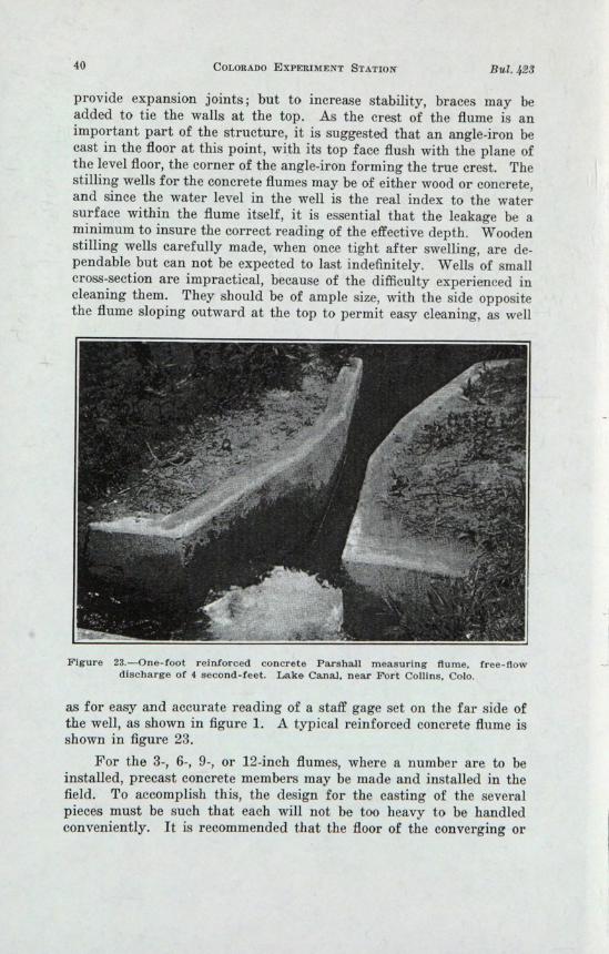
Figure I.-The Parshall Il1-easunng flume, with stilling well provided with ins-idestaff gage capable of more accurate head readings.
The Parshall measuring flume differs in design from the old typein the reduction of the convergence angle from 18° 26' to 11° 19' forits upstream or inlet section, a lengthening of the throat section from1 foot to 2 feet, reduction of the divergence angle of the lower or outletsection from 18° 26' to 9° 28', and the placing of a depression in thefloor at the throat section. The length of the side wall of the con-verging section (in feet) is also changed in accordance with thearbitrary rule
A=~+42
The length of the converging side of the structure is discussed morefully in another section of this bulletin. The length of the divergingsection has been taken as 3 feet for all widths at the throat section from1 to 8 feet inclusive. 4 In th.e old flume the floor was level throughout,whereas in the improved type the floor in the throat section slopesdownward at a rate of 9 inches vertically to 24 inches horizontally.At the point where the diverging section begins, the floor slopes upwardat a rate of 6 inches vertically to 36 incbes horizontally. The floor atthe lower end of the flume is 3 inches below the floor level of the upperor converging section. The 3-, 6-, and 9-inch flumes, discussed else-where, are of special design.
HYDRAULIC LABORATORIES
Two laboratories were used in developing this flume. At one,accurate and precise work is possible; the other is a field labora.tory
4The general dimension of the flume as s.hown in figure 1 refers to the tabulardImensions given in table I.
March 1936 THE PARSHALL MEASURING FLUME 7
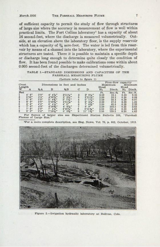
of sufficient capacity to permit the study of flow through structuresof large size where the accuracy in mea urement of flow is well withinpractical limits. The Fort Collins laboratory5 has a capacity of about16 second-feet, where the discharge is measured volumetrically. Out-side, at an elevation above the laboratory floor, is the supply reservoirwhich has a capacity of %: acre-foot. The water is led from this reser-voir by means of a channel into the laboratory, where the experimentalstructures are tested. There it is pos ible to maintain a specific depthor discharge long enough to determine quite closely the condition offlow. It has been found possible to make calibrations come within about0.005 second-foot of the discharges determined volumetrically.
TABLE I.-STANDARD DIMENSIONS AND CAPACITIES OF THEPARSHALL MEASURING FLUME
(Letters refer to figure 1)
Dimensions in feet and inchesCrestLengthW A %A B %B C D
For flumes of larger slz& see Experiment Station Bulletin 3 6, "Par hallFlumes ot Large Size."
'For a more complete description, se& Eng. News, Vol. 70, p. 662, October, 1913.
Flgur 2.-Irrlgatl n hydrauli laboratory at B 11 ue. 010.
8 COLORADO EXPERIMENT STATION Bul. 423
The volumetric tanks are of reinforced concrete, their· capacitybeing approximately that of the supply reservoir. The amount ofwater added to these tanks or basins for any particular test is deter-min.ed by hookgage readings to a limit of 0.001 foot. An electrically-driven centrifugal pump returns the water to the supply reservoir foruse again. The calibrations of the smaller flumes were made at thislaboratory, where the discharges were measured to thousandths ofsecond-feet, and the depths or heads affecting the discharge throughthe flumes were determined by hookgage readings. These experi-mental structures "\vere built of wood or sheet metal, accurate in di-mension and of sufficient depth to cover a range of discharge such aswould be found in actual field practice.
The field laboratory at Bellvue (fig. 2) is 8 miles west of FortCollins at the headworks of the Jackson Ditch, on the Cache la PoudreRiver. It consists of a reinforced concrete channel 14 feet wide and6~~ feet deep, with a present over-all length of about 150 feet. At thelower end of this channel is a vveir box 25 feet wide and 10 feet deep,having in the end wall a 15-foot standard rectangular weir. At thislaboratory, in 1923, when the calibrations were made on the largersizes of the Parshall measuring flume, the concrete weir box was ofthe same width as the channel and had a depth of 7112 feet for a dis-tance of 24 feet. In the end wall of this weir box was a 10-foot standardrectangular weir, patterned after the 10-foot weir calibrated byJ. B. Francis in the early fifties at Lowell, Mass. Because these weirswere of similar dimensions, the discharge curve for the weir used wasbased upon the results of Francis' experiments. The larger Parshallmeasuring flumes were built in this concrete channel at a point up-stream from the weir box. The water was admitted to this channel atits upper end, thence flowed through the experimental structures andfinally was carefully measured over the standard weir. Hookgageswere mounted on the model structures at such points as permittedcareful measurement of the upper head, H a , and the throat head, H b •
The head on the standard weir was determined by means of two hook-gage readings on opposite sides of the weir box (fig. 30). All hook-gage readings were observed to a limit of 0.001 foot. Do\vnstreamfrom the experimental flumes an adjustable baffle was provided whichpermitted the regulation of the degree of submergence. .At this labora-tory, calibrations were made for flows ranging from 5 to 90 second-feet.
ACTION OF THE PARSHALL MEASURING FLUME
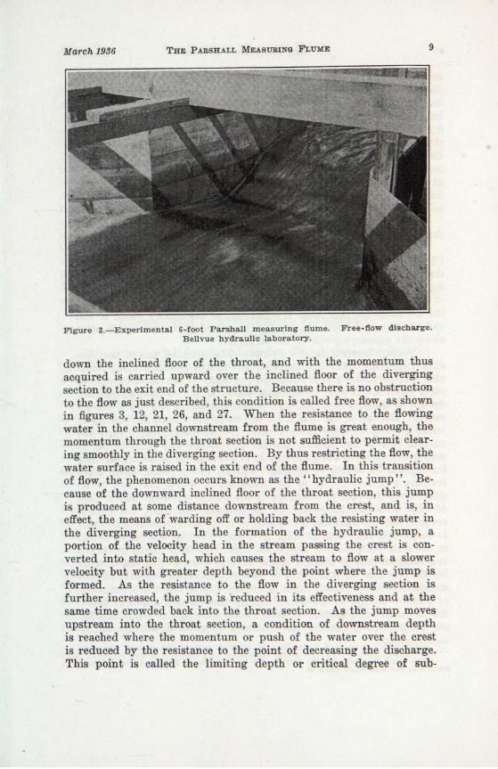
The fundamental idea dictating the design of the flume is basedupon the effect of the increasing velocity in the converging section,resulting from the constantly decreasing cross-section of the waterprism. As the flowing stream reaches the crest, which is the junctionof the upp·er level floor and throat floor, it has virtually attained itsmaximum velocity. For the free-flow condition, the stream is carried
down the inclined floor of the throat, and with the momentum thusacquired is carried upward over the inclined floor of the divergingection to the exit end of the structure. Becau e there is no ob truction
to the flow as ju t descriood thi condition i called free flow a hownin figures 3, 12, 21, 26, and 27. When the re istance to the flowingwater in the channel downstream from the flume i great enough, themomentum through the throat section is not sufficient to permit clear-ing smoothly in the di erging ection. By thu re tricting the flow thewater surface is rai ed in the exit end of the flume. In thi transitionof flow, the phenomenon occurs known as the "h draulic jump '. Be-cause of the downward inclined floor of the throat ection thi jumpis produced at some distance do nstr am from the cr t and is ineffect the means or-warding off or holding back the re . tina' water inthe diverging section. In the formation of the h draulic jump, aportion of the velocity head in the stream pa ing the re t is con-verted into tatic head, which cau h tream to flow at a lowervelocity but with greater depth beyond the point where the jump isformed. As the I' sistan e to the flow in the diverlrinO' ection ifurther incr a ed, the jump' reduc d in its ffe ti ene and at thesame time crowded back into the throat ction. the jump mo eupstream into the thro t section a ondition of downstream depthis reached where the mom ntum l' push of the water 0 er the cr tis reduced by the re istan e to th point of decreasing the di charge.This point is called the limiting d pth or critical degree of sub-
10 COLORADO EXPERIMENT STATION
mergence, and is important because it defines the limit of free-flowdischarge. The amount of water flowing will b·e undiminished untilthe water surface at the lower or downstream edge of the throat hasbeen raised to such a point that the depth here, or H b, is approximately0.76 of that in the converging section at the gage point H aJ where boththese depths are referred to the crest elevation as the datum. Whenthe resistance to the flow downstream from the structure is furtherincreased, because of lack of grade or checking of the flow by meansof flashboards, or otherwise raising the water surface beyond thislimiting depth, a reduction in the discharge results. This condition iscalled submerged flow.
In this discussion the degree of submergence is the ratio of thethroat gage, H b, to the upper gage, R a , expressed as a decimal fraction.
In the plan and elevation views of the Parshall measuring flume(fig. 13), the lower water surface, Q, in the downstream section showsthe condition of free flow, while the upper surface, P, indicates theapproximate elevation of the free-flow discharge limit. The elevationof this surface at any point between is within the free-flow zone, andthe discharge for this range is a function of the flume's width or sizeand of the upper head, R a , which is measured at the two-thirds pointalong the converging side of the structure.
CHARAOTERISTIOS OF THE FLuME.-The practical use of the Par-shall measuring flume has demonstrated that it possesses many desir-able characteristics and is not subject to many of th·e disadvantages ofother devices. It may be operated either as a free-flow, single-headdevice, or under submerged flow conditions where two heads are in-volved. Because of the contracted section at the throat, the velocity ofwater flowing through the structure is relatively greater than thenatural flow of the stream, and for this reason any sand or silt insuspension or rolled along the bottom of the channel is carried through,leaving the flume free of deposit. Velocity of approach, which oftenbecomes a serious factor in the operation of weirs, has little or noeffect upon the rate of discharge of the flume. (See discussion page44-46.) It is accurate enough for all irrigation purposes, and since itremains clear of sediment the reliability of its measurement is believedto be greater than that of other methods. Usually, conditions foundin the field will permit it to operate with a free-flow discharge, whichis a function only of a single depth, as with a weir. The loss of headfor the free-flow limit is found to be about 25 percent of that for thestandard overpour weir. There is no easy way to alter the dimensionsor cause a change in the flume, modify the channel above or belowthe structure, or otherwise interfere with the original conditions forthe pu,rpose of increasing th.e discharge to effect a wilfully unfairmeasurement.
GThis limit is applicable for flumes of I-foot widths or greater. For flume ofsmall size see dIscussion page 29.
March 1936 THE PARSHALL MEASURING FLUME 11
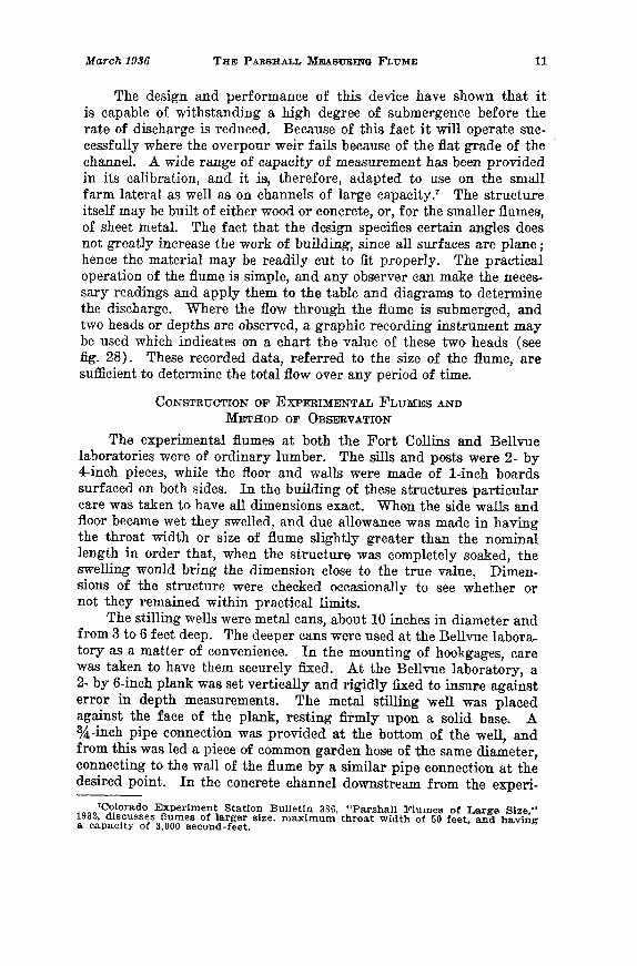
The design and performance of this device have shown that itis capable of withstanding a high degree of submergence before therate of discharge is reduced. Because of this fact it will operate suc-cessfully where the overpour weir fails because of the fiat grade of thechannel. A wide range of cap·acity of measurement has been providedin its calibration, and it is, therefore, adapted to use on the smallfarm lateral as well as on channels of large capacity.1 The structureitself may be built of either wood or concrete, or, for the smaller flumes,of sheet metal. The fact that the design specifies certain angles doesnot greatly increase the work of building, since all surfaces are plane;hence the material may be readily cut to fit properly. The practicaloperation of the flume is simple, and any observer can make the neces-sary readings and apply them to the table and diagrams to determinethe discharge. Where the flow through the flume is submerged, andtwo heads or depths are observed, a graphic recording instrument maybe used which indicates on a chart the value of these two heads (seefig. 28). These recorded data, referred to the size of the flume, aresufficient to determine the total flow over any period of time.
CONSTRUCTION OF EXPERIMENTAL FLUMES ANDMETHOD OF OBSERVATION
Th.e experimental Humes at both the Fort Collins and Bellvuelaboratories were of ordinary lumber. The sills and posts were 2- by4-inch pieces, while the floor and walls were made of I-inch boardssurfaced on both sides. In the building of these structures particularcare was taken to have all dimensions exact. When the side walls andfloor became wet they swelled, and due allowance was made in havingthe throat width or size of flume slightly greater than the nominallength in order that, when the structure was completely soaked, theswelling would bring the dimension close to the true value~ Dimen-sions of the structure were checked occasionally to see whether ornot they remained within practical limits.
The stilling wells were metal cans, about 10 inches in diameter andfrom 3 to 6 feet d€ep. The deeper cans were used at the Bellvue labora-tory as a matter of convenience. In the mounting of hookgages, carewas taken to have them securely fixed. At the Bellvue laboratory, a2- by 6-inch plank: was set vertically and rigidly fixed to insure againsterror in depth measurements. The metal stilling well was placedagainst the face of the plank, resting firmly upon a solid base. A%-inch pipe connection was provided .at the bottom of the well, andfrom this was led a piece of common garden hose of the same diameter,connecting to the wall of the flume by a similar pipe connection at thedesi:r.ed point. In the concrete channel downstream from the experi-
7Colorado Exp~riment Station Bulletin 386, "ParshallFlumes of Large Size,"1932. discusses ft.umes of larger size. nlaximum throa.t width of 50 feet, and having8. capacity of 3,000 second-feet.
12 COLORADO EXPERIMENT STATION Bul. 423
mental flume was a 22- by 22-inch metal gate, placed in a frameworkconsisting of a set of flashboards. This gate and the flashboards madeit possible to secure various degrees of submergence and to regulatethe flow through the test structure. Baffles were placed upstream fromthe exp,erirnental flume as well as downstream below the submergencEbulkhead.
Each morning before operations were begun, all hookgage con-stants were determined by means of an engineer's level and rod. Themean elevation of the crest of the test flume was accurately deter-mined by several observations at different points. A light wooden rodwith sliding target was placed at a point of mean elevation and thetarget set exactly at the line of sight of the instrument. This rod wasthen placed upon the various hooks of the gages, and'the gages wereadjusted so that th·e target again agreed with the line of sight of theleveling .instrument. The hookgage readings then gave the constant ofcorrection for each gage. This same method was employed to deter-mine the hookgag.e constants for the standard rectangular weirs.
Water was admitted to the concrete channel by means of the mainregulating gate, and after the flow had assumed a constant conditionobservations were taken as follows: An observer started by readingthe upper head, or H a , on the flume, calling this observation to a note-keeper who recorded it on a special form, and then read in properorder all other hookgages, calling the readings as they were observed.For the most part, five hookgages w·ere observed, three on the experi-mental flume and two on the standard weir. A complete round ofreadings usually required about I 1h minutes, and where the variationsin the water surface were small, fiv.e complete sets were assumed to besufficient to give the correct mean; otherwise, more observations weretaken.
In the old type of Venturi flume it was found that the downstreamflow conditions were such as to swing the current from one side to theother, apparently without cause. This swinging was found to affect thereading of head in the converging section. To d·etermine whether ornot heads observe9--_.Qn either side of the converging section of theParshall measuriIig fIu:FQ.e were the same, approximately 200 observa-tions were made iii.J923\ by having two hookgage connections, one oneach side at the prop"e.t:Joint. These observations show that the dif-ference in the two readings was very small, and it can, therefore, besafely assumed that the upper head, H a, may be observed on eitherside with equal accuracy.
At the Bellvue laboratory, the loss of head through the flume wasdetermined by staff gages read direct, the zero of the gages being setat the elevation of the floor of the converging section. These gageswere so situated that the elevation of the water above and below theflume could be determined quite accurately. At the Fort Collins
March 1936 THE PARSHALL MEASURING FLUME 13
laboratory, where calibrations wer.e made on the smaller-sized flumes ofsmall discharge, the loss of head was determined by means of hookgagereadings.
FREE-FLOW FORMULA
The data upon which the free-flow formula is based consist of thedischarges in second-feet and the corresponding heads, H a , for 159tests, where the degree of submergence is less than 70 percent, thesetests being divided according to size of flume as follows: I-foot flume,27 tests; 2-foot flume, 28 tests; 3-foot flume, 34 tests; 4-foot flume, 21tests; 6~foot flume, 20 tests; and the 8-foot flume, 29 tests. The dataobtained from the tests, when plotted to a logarithmic scale for thevarious discharges and corresponding heads, showed very nearly astraight-line variation for the various sizes of flumes tested. Uponadjusting a straight line to these individual sets of plottings, it wasobserved that the discharge intercepts for the upper head, R a , at onefoot are very closely proportional to four times the width of the flumein feet. The slope of the lines for the various sizes of flume is not thesame, thus showing that the values of the .exponent of the upper head,H a , are not identical and therefore vary with the width or size of flume.By careful inspection of the plotted data, values of the intercept andslope have been determined for each size of flume, as given in table II.TABLE IT.-VALUES OF INTERCEPT J AND SLOPE n, LOG PLOT FOR LAW
OF FREE-FLOW DISCHARGE THROUGH DIFFERENT-SIZEDPARSHALL MIDASURING FLUMES
Size of Coefficient J Exponent n of H aflume Intercept Computed Differ- Computed Differ-W log plot value 4W ence Scaled value value of ence
The fundamental law for the free-flo1v discharge through theParshall measuring flume is:
Q=JHanwh.ere Q = Quantity in second-feet
J = Coefficient ,vhich is a function of the size ofthe flume
H a = The upper head in feet observed at a pointdistant upstream from the crest two-thirdsthe length ,of the converging section
n = Exponent of tile head, H a
By inspection of the data in table II, it is evident that, as an approxi-mation, J = 4vV, vvhere W is the size of flulne or ,vidth of throat, infeet. The relation of the slope n, and width of flume W has been
14 COLO~ADO EXPERIMENT STATION Bul. J,29
6 7 8 9 10 /IPOSITIVE
4 52 3a76543 2NEGATIVE
6
4
0
~
~~~~=>~P'771 ~~~ f'7J2 j
2
4
6
o
'6
8
18
2
z
12
14
10
~(f)l&Jt-lL.oa:wm:E:JZ.J
~~lLot-ZWUcrwa.
established as n = 1.522wo.o26. Hence, the complete formula may bestated as Q === 4WHal.522Wo.o26
The form of expression employing the double exponent of H a may atfirst appear to be ,complicated and unusual. However, when thesimple operation is performed to r.educe to the proper value of theexponent for the particular width of flume, the form of the expressionfor the discharge offers no more difficulty in its solution than thesimple discharge formula for a standard weir or submerged orifice.This equation, being in the product form, is readily solved by meansof logarithms.
z
PER CENT DEVIATIONFigure 4.--Com.parison in percentage of computed with observed free-flow
discharge thro·ugh experimental flumes.
Figure 4 shows graphically the agreement of the computed dis-charge, as determined by the free~:flow formula, with the obse~ved
discharge as the base. This comparison includes, in addition t~/ the159 original tests made in 1923, the 139 check tests made in 1~( Thedata upon which tbis diagram is based were develop.ed by-expressingthe deviation between the observed and computed discharge as apercentage. Where the computed was greater than the observed dis-charge, the percentage was positive, and where the computed was lessthan the observed discharge th.e percentage was negative. A tabula-tion was then made of these values, in which zero deviation included
March 1936
Upper I-IeadHa
THE PARSHALL MEASURING FLUME
Discharge per second for flumes of various throat widths1 2 3 4 5 6 7
Table III, giving the free-flow discharge in second-feet throughthe Parshall measuring flume for sizes from 1 foot to 8 feet, is basedon the formula
Q=== 4WHa1.52ZWo.026
Figures 5 and 6 show field installations of I-foot and 2-footParshall measuring flumes operating under free-flow conditions, thelatter one being equipped with a water-stage recording instrumentgiving a record of th·e upper head, R a • There is practically no sub-mergence in the case of the I-foot flume, but in the 2-foot structurethe degree of submergence is approximately 50 percent for a dischargeof 5.7 second-feet. The loss of head in this structure was determinedroughly in the field to be about 41h inches, and by applying the datato the diagram, figure 18, the loss is calculated to be 51J! inches.
The loss of head, as referred to in this discussion, is taken as thevertical distance in feet between the water surfaces at the upstreamand downstream ends of the structure, and does not represent thetotal loss in head because the velocity heads of the inflowing andoutflowing stream through the flum.e have not been considered.
SUBMERGED-FLOW FORMULA
In the development of a formula suitable for the determinationof discharge through the Parshall measuring flume for submergedflow, various methods were attempted, a form of .equation being soughtthat would follow consistently the trend of the data and at the sametime not be so complicated as to be impracticable. The following wasthe manner of reasoning finally followed:
For the degree of suHmergence below 70 percent, it is found thata simple expression will apply in determining the rate of dischargewhere only the upper head, H a , and the width of the flume are in-volved. However, when th·e degree of submergence is 70 percent ormore the free-flow discharge is diminished slightly at first, and as thedegree of submergence increases, the rate of decrease in flow is in-creased until, near the point of complete submergence, the flow is verygr.eatly reduced. The determination of the rate of submerged flow isthen based upon the application of a certain correction to the freeflow for that particular head, H a, and the corresponding ratio of thethroat head to the upper head. As pointed out, this ratio must begreater than 70 percent before being effective in the discharge.
The experimental data upon which this correction was first basedincluded the results of 228 tests made in 1923, where the degree ofsubmergence ranged from 70 to more than 95 percent, and a range ofH a from 0.2 foot to slightly more than 2.5 feet. They were dividedaccording to size of flume as follows: I-foot flume, 46 tests; 2-footflume, 41 tests; 3-foot flume, 65 tests; 4-foot flume, 21 tests; 6-footflume, 18 tests; and 8-foot flume, 37 tests. In 1926 a series of sub-
March 1936 THE PARSHALL MEASURING FLUME 21
merged-flow tests, numbering 264, was made, and when the resultswere compared with the original submergence data it was found thata slight adjustment in the correction was n.ecessary. The combinationof all the submerged-flow tests shows the following division accordingto size of flume: I-foot flume, 80 tests; 2-foot flume, 84 tests; 3-IOOtflume, 61 tests; 4-foot flume, 64 tests; 6-foot flume, 65 tests; and 8-footflume, 116 tests. In the final arrangement 21 tests were excludedfrom the 1923 series.9
After reviewing the combined series it WM found that for highsubmergence, where the gage ratio Hb/Ha exceeded 0.95, little de-pendence could be placed upon the accuracy of the computed discharge;also, when the value of H a was 0.2 foot, the deviation between theobserved a.nd computed discharge was quite large. In the use of amore complicated expression for the determination of the correctionfactor it would be possible to reduce the error for these low heads,but for the high submergence at any head, R a , observations showmarked inconsistencies.
~For the I-foot flulne. test 6494 excluded because Ha exceeded 2.5 feet. Tests6656-57, 6707-08 excluded because Ha=0.2 foot. Tests 6684, &700, 6705 excluded be-cause submergence exceeded 95 percent. For the 2-foot flume, test 6624 excludedbecause submergence exce-eded 95 percent. Tests 6642-43 and 6646 excluded be-cause Ha=0.2 foot; 3-foot flume. test 6583 excluded because submergence exceeded95 percent; and tests 6579-80-81 excluded because Ha=0.2 foot; 6-foot flume, tests6342 and 7079 excluded because submergence exceeded 95 p'ercent; 8-foot flume,tests 7020-29 excluded because submergence exceeded 95 percent. Of the 471 sub-merged flow tests falling within the prescribed limits, test 6335 was excludedbecause of gross error.
Figure 7.-Me-aning of correction factor, C, in second-feet, to be subtracted fromthe free-fio'w discharge for a definite value of Ha and
a. certaJn degree of subme~gence.
22 COLORADO EXPERIMENT STATION Bul..q23
These data were plotted as shown in figure 7, where the severalcurved lines represent the degree of submergence. For any particularpoint on the submergence line there will be a definite valu.e, C, asshown, which is the amount in second-feet to be subtracted from thefree-flow value for that particular upper head, H a , to give the sub-merged flow. It will be observed that as the value of H a increases, theamolillt of the correction also increases for any particular degree ofsubm.ergence. It is found that for the relation existing between thecorrection factor, C, for submergence and the upper head, H a , for anydegree of submergence, K, the general expression may be stated thus:
{Ha}DCk = T +B
where Ck is the correction in second-feet for the degree of submergenceK, expressed as a decimal fraction, and H a upper head in feet. A andB are values d,ependent on the gage ratio or degree of submergence,K, and n, an exponent, also depends on K. Base equations were de-veloped for various values of K, ranging from 0.70 to 0.95, and fromthese the law of variation of A, B, and n was determined. Thisrelation for the I-foot flume is as follows:
) 4.57 - a.14K
Ha ~Ck = j-l.-S-t-1-.s---( + O.093K
)Jr-f -2.45)
For the other sizes of flume it was found by introducing a multiplyingfactor to the value of C that a practical agreement with the observedsubmerged flow was possible. This factor, M, varies with the widthor size of 'flume, W, according to the simple relation M = W O. S15•
The following is the complete formula for computing the dischargethrough the Parshall measuring flume for submerged flow:
This formula is not, in its complete statement, a simple expression;however, when the value of K, the degree of submergence expressedas a decimal fraction, is properly substituted, the formula, or thatterm representing the correction C, becomes much simplified.
To facilitate the use of this submerged-flow correction formula.,the values of C for a I-foot flume may be taken directly from thediagram, figure 8. To determine the submerged-flow correction forother sizes of flume, multiply this correction by the factor M, as given
0'?J./ V !/ ./ ./ ./ ....- 1/~ S V./ ./ ./" V- 17 ./ ./ ....-
6~~·/"././ ./ /" ./ ./ l/ ././ ./ ./ ./ ./
,,~~J/'./ ~ v/ ./V./ ./ ./ / ./ VV V ./' ./ / ./ V ./
1('~~rtO ~ "tAr '\0 ~_1iP 1.6l- ~ ~. ~ (J ~ C!./ ./ V ./ V .// ./ V /' /'" / ./
/ / ./ /' / ./ /' /' V / V./ /'
/ // V / / /' V ,/" V ./V v ./V
// / ./ V / ./ ./' V /' V V VII / / / V / ./ / V /'Y V
I / 1/ / / V '// / /V/V V5
1//1/ /'~Y/ y V~V VV/V/ ./ ./V
ilf/ / ~,... b/ V V V/f}~~~~ fb,... Q) I:Qtbl/qa I/q1- I./~t-
2.0
2..5
roC:X 1.0
~ 9w .8%
,7a:~ .6Q.J
..306 (}7 De 09 JO 125 J5 J75.2 .25 .3 35 A 5 6 7 .8 .9 to 125 1.5 175 2 25 3 3.5 4 4.5 5 6 7CORRECTION· CUBIC FEET PER SECOND
Figure 8.-Diagram for com·puting submerged flow through I-foot Parshallmeasuring flume.
in the following tabulation, before subtracting from the correspondingfree flow for that particular H a head.Size of flume Multiplying factor Size of flume Multiplying factorWidth in feet
1234
1.01.82.43.1
Width in feet5678
3.74.34.95.4
Figure 9 shows the agreement of the observed and computeddischarges for submerged flow. The manner of compiling the data andconstructing this diagram is identical with that given for the free-flowdischarge. In the comparison of computed and observed dischargesfor the total 470 tests, it was found that 87 percent were within 5percent of the observ.ed value.
In the comparison of the free-flow and submerged-flow errordiagrams, it is evident that the accuracy of the measurement is greaterwhere the device operates under a free-flow condition.
In determining the rate of discharge through tile Parshallmeasuring flume under submerged flow, the following examples aregiven to illustrate the method of computation: .
(1) Let it be assumed that the flume has a throat width of onefoot; upper head, H a , 1.50 feet; and the throat head H b , 1.20 feet.The ratio 1.20/1.50 = 0.80. Enter diagram, figure 8, at the left handside on the H a line 1.5, follow this horizontal line to the right untilreaching the curved line 80. Vertically beneath this intersection ob-serve the reading 0.71, which is the correction in second-feet due tothe submergence. In the free-flow discharge, table III, for th·e I-footflume with the recorded head, Ha~ of 1.50 feet, note that tIle dischargeis 7.41 second-feet. The flow with a submergence of 80 percent underthese conditions will, therefore, be 7.41- 0.71 = 6.70 second-feet.
(2) Wh.at will be the discharge through a 4-foot fluDle wherethe upper head H a is 1.98 feet and the throat head, H b, is 1.80 feet Y
24 COLORADO EXPERIMENT STATION But 429
- F"/Jf?jfa__ vnmr-oJ~grn~ [§j~~ J?J~mP'7l[ZjP7.1
The ratio 1.80/1.98 is very closely 0.91. As before, enter the correc-tion diagram at the left; however, in this case follow to the right alongthe horizontal line indicating H a = 2.0 until the point is reached mid-way between curved lines 90 and 92. It is to be kept in mind that theline H a = 2.0 is slightly above the true value of the upper head, whichis 1.98 feet. At this corrected point, move vertically downward to thebase of the diagram and estimate the value on this scale at 3.50 second-feet, which is the submergence correction for a I-foot flume. It willbe noted in the previous tabulation that the multiplying factor, M,for the 4-foot :flume is 3.1. This factor times the correction in second-feet is 10.85 second-feet or the amount to be deducted from the freeflow through the 4-foot flume for an upper head H a of 1.98 feet. Thecomputed submerged flow is therefore 36.17 second-feet.
(3) Suppose the upper head, R a , of an 8-foot flume is 0.69 footand the throat head, H b , is 0.60 foot, what would be the submerged-flow discharge' The ratio of the two heads will be 0.60/0.69 or veryclosely 0.87. As before, enter the correction diagram at the left andfollow horizontally to the right OIl, the line 0.7 to a point about midwaybetween the curved lines "86" and "88". Since the value of the H ahead is 0.69 foot, it will be necessary to select the true point aboutone tenth the interval below the 0.7 H a line. Vertically below thisfinal location of the true point there will be found, on the base of thediagram, the value of 0.41 second-foot as the correction for sub-mergence for the I-foot flume. The multiplying factor, M, for the8-foot flume will be 0.41 times 5.4 or 2.21 second-feet. The free-flowdischarg.e through the 8-foot flume for an upper head, R a , at 0.69 footis 17.63 second-feet. The computed submerged flow will be 17.63 -2.21 = 15.42 second-feet. ~"or this degree of sub·mergence it is readilydetermined that the free-flow discharge has been reduced approxi-mately 12.5 percent.~ 18
Figure 9.-Comparison in percentage of computed with observed SUbmerged-flowdischarge through experimental flumes.
March 1936 THE PARSHALL MEASURING FLUME 25
The error in calculating the submerged-flow discharge, resultingfrom observing either the upper head or the throat head 0.01 foot toolarge or too small, is found for Ha heads of 0.5 foot and submergences75 to 90 percent to range from a.bout 1 to 10 percent, while for 95percent submergence this error may be 20 to 30 percent. For H a headsof about 2 feet this error for submergences, 75 to 95 percent, wouldbe 5 percent or less.
In order to make a field comparison between the computed dis-charge of a Parshall measuring flume and an ordinary rating flume,there was built a 6-foot flume in a ditch at Rocky Ford, Colo., asshown in figure 10. This flume was provided with stilling wells forboth the H a and H b gages. An index was fixed near the top of eachwell, which made it possible to determine the heads to 0.01 foot bymeans of a depth gage. Reference points in the upstream and down-stream wings of the structure were used to determine the loss of head.
An ordina.ry rating flume, previously constructed in the ditchat a point about 100 yards downstream, was calibrated by current metergagings and used to determine the discharge of the Parshall measuringTABLE lV.-COMPARISON OF COMPUTED DISCHARGE THROUGH A 6-FOOT
PARSHALL MEASURING FLUME WITH THAT DETERMINED BYMEANS OF A DISCHARGE CURVE FOR AN ORDINARY
RATING FLUME, ROCKY FORD DITCH,ROCKY FORD, COLO.
(The values of Hll and Hb are single observations; that is, they are not the meanof several trials in the determination of these heads.)
Currentmeter gag-
Com- Rating ings in rat-Six-foot Parshall Loss puted flume* ing ft.ume**measuring flume Ratio of dis- Dis- Differ- Devia- Dis-
Date H. Hb Hd Hb/Ha Head charge Gage charge ence tiOD Gage chargePer Sec.-
9/2·8 2.16 2.05 .11 .949 .08 56.7 1.86 55.0 +1.7 3.1*The gage indicated is the reading at the time the heads were observed on
the Parshall measuring fiulue. The corresponding discharge in second-feet 'wastaken from a mean curve based on the current meter gagings given in this table.This rating flun1e is located in the same channel as the 6-foot ft.ume.
*·Current n1eter gagings in rating flume in second-feet, with correspondinggage in feet. T'hese gagings made on dates indicated.
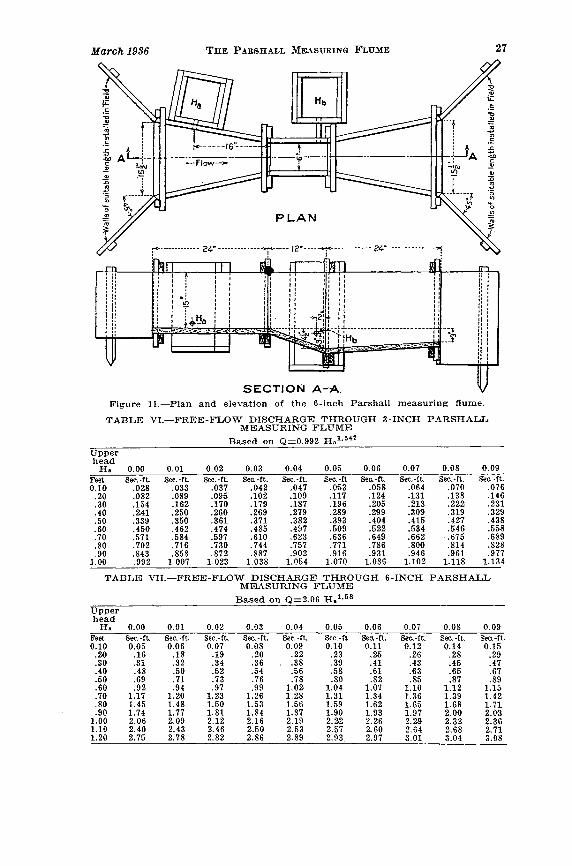
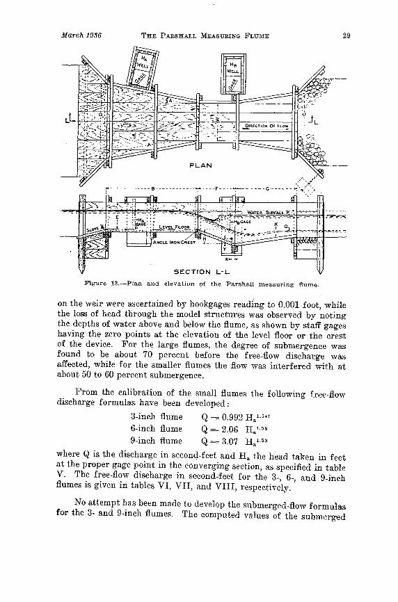
Figure 13.-Plan and elevation ()f the Parshall measuring flume.
on the weir were ascertained by hookgages readi'ng to 0.001 foot, whilethe loss of head through the model structures was observed by notingthe depths of "vater above a.nd below the flume, as shown by staff gageshaving the zero points at the elevation of the level floor or the crestof the device. For the large flumes, the degree of submergence ,vasfound to be about 70 percent before the free-flow discharge wasaffected, while for the smaller flumes the flow was interfered with atabout 50 to 60 percent submergence.
From the calibration of the small flumes the following free-flowdischarge formulas have been developed:
3-inch flume Q = 0.992 H al.54i
6-inch flume Q= 2.06 H a l.58
9-inch flume Q = 3.07 H a1.53
where Q is the discharge in seconq.-feet and H a the head taken in feetat the proper gage point in the converging section, as specified in tableV. The free-flo'\v discharge in second-feet for the 3-, 6-, and 9-inchflumes is given in tables VI, VII, and VIII, respectively.
No attempt has been nlade to develop the submerged-flow formulasfor the 3- and 9-inch fluID,es. The COlllputed values of the submerged
32 COLORADO EXPERIMENT STATION Bul. 423
may be measured through flumes of various sizes, and the selection ofthe proper size to use for the conditions imposed requires carefuljudgment. From the standpoint of economy, the smaller the flume theless its cost; but to crowd the full discharge through it may requiretoo great a loss of head, which, in turn, would mean greater expensein strengthening the banks of the channel above the structure, aswell as providing additional protection to the channel below if theflume is operated under free-flow conditions.
The flume's capacity, or quantity of water to be measured, mustfirst be determined, due allowance being made for additional flowowing to floods or future enlargements of the channel. On the otherhand, there is danger in selecting a flume having too wide a throat.If the structure operates under free-flow conditions, the change inupper head for given fluctuations in the discharge will be less for largethan for small flumes. It is believed to be the better plan in theoperation of large flumes to set the crest elevation so as to have freeflow for the low-to-moderate discharges and submerged flow for high
I I I v..........- l/'I I I~~~~ ~./V .. 1//I I ~Q' /'/'~~....... ;//f r;,~Cp;// /": /./ v //v()qo""'v//./ ,/ ~ ,/'/ /
~~ ,,0[../""" V ./ /,/r/ /~",o V ./v~ ?~o ./ /.'/vv
PERCE.NTAGE OF' SUBMERGENCE LOSS Of' HEAD IN F'EET'
Figure l8.-Diagram for determining the loss of head through the Parshallmeasuring flume.
March 1936 THE PARSHALL MEASURING FLU)IE 33
discharges. Figure 17 shows a 6-foot flume carrying 64 second-feet,where the loss in head is approximately 0.85 foot a.nd the degree ofsubmergence about 60 percent. This is considered an ideal conditionbecause the degree of submergence is less than 70 percent, the dischargeis a function of a single head or depth, and the exit velocity is moderate.
·To assist in the selection of the proper size of flume to meet certainrequirements, the diagram shown in figure 18 is given. The use of thisdiagram may best be illustrated by an example: Let it be required tofind the loss of head through a 2-foot flume operating at a submergenceof 85 percent and discharging 20 second-feet of water. Enter thediagram at the lower left and follow vertically on the line 85 until thecurved discharge line 20 is reached. At this point move horizontallyto the right until the sloping line 2 is intersected and then drop ver-tically to the base line and note the loss of head to be 0.33 foot. Thisloss of head, as previously explained, is the vertical distance in feetbetween the vvater surface above and below the structure.
The follo1ving discussion is presented citing a practical case suchas would be found in the field in selecting the size and setting of theParshall measuring flume best suited to meet the following require-ments: ..A..ssume that the channel is 10 feet wide, with the inside slope
Figure 19.-Section of ftunle as an aid in the deternlination of the propercrest elevation.
of the banks 1 to 1, the depth of ,vater 2 feet, and the maximum dis-charge to be measured 50 second-feet. It is required to select theproper size of flume, to determine its proper setting in elevation \vithreference to the grade of the channel, and to approximate the conditionof flo,v upstrea.m from the flume after it has been installed.
Generally, the width of the throat of the flullle will be from onethird to one half the width of th.e channel; hoV\rever, for wide, sh-allowchannels or deep, narrow ones this general statement "Tould not hold.The size of channel, depth of water, extent of free board, together withother limiting factors, must all be considered in the final selection ofthe most pra.ctical size of structure. For the 10-foot channel asassumed, the proper width of throat ,viII probably be 3, 4, or 5 feet.
From the diagram, figure 18, for the 3-foot flume operating at alimiting subluergence of 70 percent and a. discharge of 50 second-feet,it vvill be noted that the loss of head through the structure ,viII be 0.86
34 COLORADO EXPERIMENT STATION Bul·423
foot or about 10l/± inches. For this condition of flow the depth ofwater upstream from the flume, when discharging 50 second-f.eet, willbe 0.86 foot greater than that downstrealTI, or a total of 2.86 feet. Onthis basis it will be necessary to examine the matter of a safe, free boardfor that portion of the channel upstream from the flume, as well as todetermine whether or not this increas.e in depth will interfere withdiverting the flow through the headgates if the loca.tion of the flumeis near the point of diversion. If a submergence of 90 percent is takenas the limit, then the loss of head will be reduced to about 0.32 foot.It is to be pointed out for the case of this high submergence that bothth·e H a and H b heads will have to be observed in order to compute thedischarge, whereas, for the submergence of 70 percent only the H a headwould be required.
Investigating a 4-foot flume setting for 70 percent submergencea.nd a discharge of 50 second-feet, it is found from the diagram thatthe loss of head will be 0.70 foot or about 8112 inches. The loss of headthrough the5-foot flum.e for these same conditions "vill be 0.60 foot orabout 714 inches. Comparing these values of loss of head, it will benoted that by increasing the size of flume from 3 to 5 feet the loss ofhead decreased from .86 to .60 foot or about 3 inches. It is usuallyfound that the saving of an inch or so in the loss of head does notwarrant the selection of the larger flume, because of the increased costof the structure. It is recommended in the selection of the prop·er sizeof flume that a submergence of 60 percent be taken as the more practicallimit to use in approximating the size of structure, provided it isintended to operate the flume as a single-head device. For this degreeof submergence, a moderate range in th.e fluctuation of the depth ofwater downstream from the flume may be tolerated without exceedingthe free-flow limit of submergence of 70 percent.
It appears that the use of the 3-foot flume would result in toogreat a loss of head; and by the use of the 5-foot flume, when operatingunder like conditions of a flow of 50 second-feet and 70 percent sub-mergence, a saving in loss of head of 3 inches would be gained.In either case this saving of 3 inches may not be of any greatimportance, whereas, the cost of the 3- a.nd 5-foot flumes would differmaterially. If conditions will permit, it is obvious that the 3-footstructure should be selected, primarily from a cost standpoint. How-ever, it must be appreciated that, "\vhen passing 50 second-feet througha throat 3 feet wide, the velocity of the stream would be relatively highand adequate protection against scour downstream from the structurewould be required. .As the size of flume increases the loss of head willdecrease, and likewise the velocity of the stream through the throatwill be less. If the 8-foot flume was considered, the loss of head wouldbe reduced to slightly less than 6 inches, and the velocity likewiselessened; but the saving in loss of head probably would not "Tarrant
March 1936 THE PARSHALL MEASURING FLU~fE 35
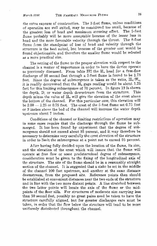
the extra expense of construction. The 3-foot flume, unless conditionsof operation are well suited, may be considered too small, because ofthe greatest loss of head and maximum scouring effect. The 5-footflume probably vviII be more acceptable because of the lesser loss inhead and the more favorable velocity through th.e throat. The 8-footflume from the standpoint of loss of head and velocity through thestructure is the best suited, but because of the greater cost would befound objectionable, and therefore the smaller flume would be selectedas a more practical size.
The setting of the flume to the proper elevation with respect to thechannel is a matter of importance in order to have the device operateas previously discussed. From table III the H a head for a free-flowdischarge of 50 second-feet through a 5-foot flume is found to be 1.78feet. Since the degree of submergence is taken as the ratio, Hb/Ha ,
it is readily determined that the lib gage reading would be about 1.25feet for this limiting submergence of 70 percent. In figure 19 is shownthe depth, D, or water depth downstream from the structure. Thisdepth minus the value of H b will give the elevation of the crest a.bovethe bottom of the channel. For this particular case, this elevation will00 2.00 - 1.25 or 0.75 foot. The crest of the 5-foot flume set 0.75 footor 9 inches above the bed of the channel will increase the water depthupstream about 7 inches.
Conditions of the channel or limiting restrictions of operation mayin some cases require that the discharge through the flume be sub-merged. It has been found by experiment that the degree of sub-mergence should not exceed about 95 percent, and it may therefore benecessary to determine very car.efully the crest elevation of the structurein order to limit the submergence at a point not to exceed 95 percent.
After having fully decided upon the loca.tion of the flume, its size,and the elevation of the crest which will insure that the flume willoperate at free flo\v or some predetermined degree of submergence,consideration must be given to the fixing of the longitudinal axis ofthe structure. The site of the flume should be in a reasonably straightsection of the channel. It is suggested that a stake be set in the middleof the channel 100 feet upstream, and another at the same distancedownstream, from the proposed site. Reference points then shouldbe established at convenient distances near the two ends of the structureand in line with the two more distant points. A line stretched betweenthe two latter points will locate the axis of the flume or the mid-points of the floor sills. For structures of moderate size carrying lessthan 50 second-feet, possibly no great pains need be taken to have thestructure carefully aligned, but for greater discharges care must betaken, in order that the flow belo,v the structure will tend to be moreuniformly distributed throughout the channel.
38 COLORADO EXPERI~IENl' STATION Bul.423
between them horizontal. If it is desired to have the cracks parallelthe slope of the floor, the pieces composing th·e throat walls would b€cut as parallelograms, with the end cuts on a skew of the ratio 9/24.As the top of the wall will then have a slope equal to that of the floor,the downstream end will be low by 9 inches. If the flume is to beoperated under free-flow condition, the height of walls in the divergingsection'may be less than the converging or upstream part; and, there-fore, the top of these walls may be made to agree with the low pointof slope of the throat wall. This method of building will reduce theamount of material jn the structure. It is suggested, however, thatthe bottom pieces in the walls of the downstream or diverging sectionbe so cut that the top edges will be level, thus leaving the finished tophorizontal. A typical 8-foot framed Parshall measuring flume is shownjn figure 21.
After the walls have been placed, the floor is laid. Since the floorsof the upstream and downstream sections taper, special pieces willneed to be cut to fit. The lower end of the level floor, which forms thecrest, should be smooth and even. At this point the throat floor isjoined and the pieces forming this inclined floor should be cut on abevel of 9/24, which will fit closely to the ends of the level floor. It isdesirable to use an angle-iron cr.est for the framed structure. Thismetal piece is to be dapped in at the downstream end of the level floorof the converging section and made flush with the floor line. Thisshould be set before placing (he throat floor. The placing of the floorafter the walls have been set holds the bottom course of the walls inposition and prevents the outside earth pressure from dislodging orcrowding the walls and altering the inside dimensions. The tendencyof the larger wooden structures to float should he given consideration,and it is recommended that posts or piling be driven down to tie thesills securely. The cut-off walls set at each end of the structure willaid in holding the flume in place. A plank laid along the outside ofthe flume walls on the ends of the sills will resist the uplift after back-filling has been placed. Where the discharge through the flume is 50second-feet or more, the contraction effect set up by the water enteringthe flume where the 45-degree wings are attached causes a disturbance.A better entrance condition is secured by setting these wings back frOIDthe flume and then joining them to it by a sheet metal section rolledto a radius of 30 to 60 inch.es. The downstream 45-degree wings maybe attached directly to the structure.
For moderate flows through the smaller flumes, the downstream'\vings may be placed at right angles to the axis of the flume, as shownin figure 12. For the larger discharg.es, some protection to the bottomof the channel immediately upstream from the flume may be necessary.Large flat stones or heavy gravel would, under ordinary conditions,provide ample protection. For fr.ee-flow Gonditions, the exit velocity
March 1936 THE PARSHALL MEASURING FLU::\IE 39
GAGE WELLS
ELEVATION & SECTION ON A-A
I-t-
II
-t-
-----.f~2~O"---""--3'-<J"~I
I I. I I
f il- r- t .:----L~ ,...1 -1-__4
Ti REtNFO~C1NG
I 40 I II'~ I : \tHaGAGf: CONNECTION1+- .e.: 2X2X!"'ANGLEr - ,~ C)I ~ .."I'.!.I
Figure 22.-Plan and elevation of a 2-foot reinforced concrete Parshall measuringflunle.
is quite high, and where the channel is in earthy section, ample pro-tection must be provided. To prevent bottom scour, a wire mattressfilled with cobblestones and brush has been used successfully. Thismattress is attached to the IOV\7er end of the structure and laid trans-versely to the axis of the channel. The top and bottom webs of themattress should be securely wired together. These vertical wires willprevent the material within the mattress from collecting at the loweTside. Being flexible, the mattress will sag down if any cutting occursand· form a protection for the lo\ver ·end of the structure. Bankprotection may be provided in the same manner downstream fromthe outlet of the flume.
The Parshall measuring fhllue luay be constructed of concrete,as suggested in the plan shoV\7n in figure 22. The construction ofconcrete flumes is similar to that of any ordinary reinforced structure.Because of the flume's relatively short length, it is not necessary to
lJtlarch 1936 THE P ARBHALL MEASURING FLUME 41
upstream section, a.nd the floor of the throat section, be cast as onepiece, with a light angle-iron cast into the face at the crest. A ribshould be cast longitudinally along the center line on the bottom sideto strength-en the members while they are being handled, and a grooveshould be formed at the proper distance along the sides, top face, tolocate and fix the position of the side walls. Each of these side wallsshould be cast as a flat slab of the proper dimensions, with a projectingt.ongu-e on the sides to engage the grooves of adjacent members. Stubbolts cast into the top face of wall members will :fix: crossbars or strutsto resist displacement after the structure has been assembled. Tubesshould be cast at the proper points, both in the converging and throat'valls, to ':vhich stilling ""veIls -may be attached for the measurementof heads. The \vells may be made of lumber (figs. 1 and 11) set to fitthe tube connections, or for moderate depths of flow they may be ofordinary se\ver tile set into a. concrete base, with the connecting tubereaching through a hole in the side. (Sections of old stave pipe maybe used as stilling wells.) This arrangement will not permit the useof a vertical scale in the_ tile or pipe to determine the head, but a scalemeasuring down to the water surface from a fixed point at the top maybe used. This distance subtracted from the elevation of the fixedpoint above the crest of the flume will give the effective head.
In building a concrete flume in place, a suitable foundation isfirst prepared in the bottom of the channel. The forms for the floorare set to a grade such that, when struck off, the floor of the con-verging section is level, and the floor of the throat and divergingsection have properly inclined slopes. For all structures built in achannel, it is necessaT~Y to guard against the possibility of th-e water,vashing heneath the structure. It is recommended that in preparingthe foundation a trench be cut crosswise, which, when filled with con-crete, ,vill form a cut-off wall at each end of the structure and be madea part of the floor itself; and that the concrete wings be set down deepenough and into the banks far enough to prevent the water fromcutting around the sides. The lower parts of the wing walls shouldbe cast at the same time as the floor system. In building small struc-tures, before the concrete sets, short pieces of reinforcing bars or scrap-iron may be placed at intervals along the edges of the floor in suchnlanner that when the ,valls are east they "rill strengthen the structureagainst possible cracking or rupturing at the floor line. After thefloor has set hard enough to permit ,vork to be done on it, the formsfor the side walls are placed and braced securely to prevent possibledisplacement. Before the ,valls are poured, the surfaee of the floor,vhich is in contact ,vith the ne"T wall should be cleaned thoroughly inorder that a proper bond may be secured.
44 COLORADO EXPERIMENT STATION Bul. 42f~
EFFECT OF VELOCITY OF ApPROACH ON THE ACCURACY'OF l\tIEASUREMENT
To test th·e effect of velocity of approach, a series of observationswas made on the 2-foot flume at the Bellyue laboratory. The floor ofthe channel immediately above the flulue structure was built level, ofI-inch boards, this floor being in reality. merely an extension of thefloor of the converging section of the- experimental flume. Verticalwing walls vvere placed at an angle of 45 degrees to the longitudinalaxis of th·e flume from the upper ends of its converging section, thesewings extending back on each side to the concrete walls of the labora-tory channel. Movable partitions "rere set up in a vertical position onthe floor of the approach section, one on each side of and parallel tothe axis of the cha.nnel, with the lower or downstream ends againstthe wings. Tests were made with widths of approach channel varyingfrom a maximum of 11.1 feet to a. minimum of 6.0 feet. In 1932 furthertests were made in the laboratory on the standard 2-foot Parshallmeasuring flume, where these movable partitions were set "\vith thedownstream ends against the llpstream ends of the converging sectionor set apart 3.96 feet. The results of this entire series of observationsfor free flow are given in table' IX.
In the last column of this table, showing ratio of velocities inpercentages, it appears that for the narrow channel, about 4 feet inwidth, the velocity of approach is practically three times that for thestandard condition of 11.1 feet. To determine these values, the velocityof approach in feet per second was ca.refully plotted against the upperhead, H a , where the width of channel was 11.1 feet. The mean curvewas drawn through these points, which gave the values near 100percent as indicated. Then for the oth·er widths of channel, thevelocity of approach for the corresponding head was dete-rmined frolnthis mean curve, and this value was compared with the actual velocityof approach. These tests indicate that the maximum increase to about300 percent in velocity of approach does not cause a significant changein the discharge, as the variation is less than the experimental error.
The Pa.rshall measuring flume is primarily intended to operatellnder conditions where the velocities are moderate. There may becases where the channel in which the measurement is to be made has arelatively steep grade or narrow section, and the velocity of the flowingwater is considerably above that ordinarily encountered. Th·e con-verging section of the flume through which the water passes in ap-proaching the throat automatically controls the velocity of the streamas it flows over the cr:est of the device, providing the approachingstream to the structure shall be flowing at streaming stage or less thanthe critic&l velocity. This implies that the grade of the channel lead-ing to the structure shall be reasonably gentle. However, if conditio-usare such as to cause high velocities of the appYoaching Rtr0cun, then a
48 COLORADO EXPERIl\lENT STATION' Bul. 423
limitations of bottom alld side distances, the velocity of approach shouldbe about lh foot per second, and th.e error from this source ahout 1percent of the discharge. 'To take the extreme case where the bottomand. side distance are each V2 foot for a I-foot rectangular \veir \vitha head of 0.6 foot, the error in discharge due to the velocity of approachis found to be 4.6 pereent. For these sa.me distances and head, but,,~ith a 4-foot rectangular ,veir, the error in discharge is 10.5 p¢.For a I-foot and a 4-foot ,veir, with I-foot head a.nd the bottom andside distances each at 1 foot, the error in discharge is 2.8 percent a.nd6.8 percent, respectively. As the head increases, th·e error also in-c.reases, assun1ing that t.he bot torn and side distances remain fixed.For this fixed eonditioll the error jnereases as th·e length of crest isincreased.
(JOMPARISON OF Loss OF HEAD FOR VARIOUS DISCHARG~ OVERSTANDARD WEIRS AND THROUGH THE PARSHALL MEASURING FLUME
'rable X has been prepared to show the relative 108.'5 of 11ead in feetfor various discharges through the fllune and over weirs. For the 6-inch flume the degree of submergence at 50 percent was taken as thelimit of free flow, while for the 1-, 2-, and 4-foot flumes the limitingp.ercentage was taken at 70. It is to be noted in this comparison thatthe values given under the headings for the various weirs representthe actual head on the crest to give the corresponding discharge. The
"loss of head is, in reality, greater than that indicated by the distancebetween the water surface dOvvnstream from the weir a.nd the crest.This additional fall is necessary to permit the free passage of airunderneath th·e nappe, or overpouring stream of water, a11d may beassumed to be from 0.05 to 0.10 foot.
ACCESSORIES
For small flows through the Parshalilneasuring flulne, a staff gageset flush ,vith the inside face of the converging section at the properdistance ha.ck from the crest may be found satisfactory to determinethe upper head, R a , for free flo'v. For higher heads it has been foundinadvisable to use the staff gage placed on the inside face of the flume.If the flow is submerged, the throat gage on the inside face will befound unsatisfactory because of th.e roughness of the water surface.As the degree of submergence increases, the water becomes· less dis-turbed; but for high submergence the error in reading the head maycause a large error in the computed discharge, even though the readingmay be carefully observed. It is thought, however, that more sa.tis-factory results will be obtained by placing the staff gages, or scales, inthe stilling wells as suggested in figure 1.
For important installations of the Parshall measuring flume ,vherp.pernlH.l1p.nt rer,01"(Js of the flovv flre dp.sil"ed, there ha~ heen <ip.Rlgllerl a,
50 COLORADO EXPERIMENT STATION Rul·423
bold-faced type the rate of free-flow discharge in second-feet. TheH a drum with its discharge graduations is especially designed for anyparticula.r size of flume. These instruments are designated as "righthand" or "left hand ", according to whether the H a drum is at theright or left when facing the instrument. This arrangement is neces-sary as a convenience to operation, depending on whether the stillingwells are located on the right- or left-hand side of the flume.
Each pen used to scribe the graphs on th·e graduated chart ismounted on a suitable headblock carried at the upper end of a verticalrack, meshing with a small gear of proper diameter attached to theshaft carrying the sprocket wh.eel and indicating drum.
Parallel guiderods direct the pens vertically along the hour-lineof the chart. Each pen is synchronized to the drum reading for gageheight, and since the index line crosses more than one line of gradua-tions, it is only necessary to read approximately the indicated chartreading and then observe to close limits the actual value of the headas shown on the drum.
In th.e operation of this instrument, the only manipulation neces-sary is to remove the cylinder, wind the clock, and change the chart ..To remove the cylinder, the H a and H b pens a.re lifted from the chartby a suitable lever arrangement, and the cylinder is then lifted verti-cally from its pivot support. The key for winding is attached to theclock movement and extends to the top of the cylinder. An orna-mental cover fits snugly over the top as a protection. The blank chart,cut to fit, is laid around the cylinder and rests against a ring projec-tion at the bottom. Rubber bands are used to hold the sheet in place.Paste may be used to seal the edges if desired.
The distance between sprocket wheels is 18 inches, and whereI2-inch floats are llsed only 6 inches are available to clear th.e verticaldiaphragm in the float wells. If a concrete partition wall is used toseparate the H a and H b compartments) it is. found that with a practicalthickness of wall there is not sufficient safe margin or clearance for thetravel of the floats. A metal diaphragm, with horizontal angle-ironstiffeners, occupying only about 2.5 inches, is more suitable forseparating the compartments.
To locate properly the position of the instrument on the cabinet,it is necessary to plumb carefully from the diaphragm up to the underside of the top of the cabinet, and there drive through a nail. Fromthe point thus obtained on the top, the places for the holes for the-sprocket chains a.nd those through which th·e penracks are to pass nlaybe marked. To provide ample clearance, I-inch auger holes are recom-mended. The instrument hase is now shifted to position and firmlyfixed by screws at the ·ends. The sprocket chains are threaded through,and the float and counterweight are attached. The mounting andsetting of the instrument require no special expert mechanical skilL
52 COLORADO EXPERIMENT STATION Bul·423
of the correction which must be made hy adjusting the lock-nutattachment at the floa.t~ The comparison of both drums and finaladjustments must be made before actual discharge calculations arepossible.10
GENERAL COMMENT AND NOTES CONCERNING ORIGINAL DATA
The original data given in tables XI to XXIX constitute theresults of the complete series of both free-flow and submerged-flowtests used in the determination of the discharge formulas for thesetwo conditions.
Tests 6295 to 6494 were made in 1923 at the Bellvue laboratory,where a standard 10-foot rectangula.r weir was used to determine theobserved discharge through the various sizes of experimental Parshallmeasuring flumes. For the smaller discharges, experimental flumes of1-, 2-, and 3-foot sizes were tested at the Fort Collins hydraulic labora.-tory as indicated in the tables which follow.
Tests 7015 to 7138 were made in the fall of 1924 at the Bellvuelaboratory, where the 10-foot standard rectangular weir was used toobtain the observed discharge. Only a limited number of this series oftests was used in the comparison because they were purposely run athigh submergence and H a depths greater tha.n 2.5 feet. The few testsconsidered were made a part of the 1923 series, as th.ey were used inthe original derivation of the c1is.charge formulas.
Tests 7285 to 7554 were made in 1926 at the Bellvue laboratory,where a standard 15-foot rectangular weir was used to determine theobserved discharge, figure 29. Tests 7555 to 7615 were also made atthe Bellvue laboratory, but apply to a different device. A standard4-foot rectangula.r weir was used in tests 7616 to 7712, figure 30, whilefor tests 7713 to 7756 an 18-inch rectangular weir was used. Tests7757 to 7773 were made where the I5-foot weir was used to determinethe discharg.e. It will be found for tests on the 2-foot flume that fourdifferent-sized weirs, as well as volumetric determinations of discharge,were used in the calibration.
The computed discharges for tests 7674 to 7683, I-foot flume, ,verereduced by 2 percent b-ecause the dimension of width of throat wasincorrect.
Tests 7379 to 7388 were made on the 8-foot Parshall measuringflume as special ohservations to determine the effect. of increasing thelength of the converging section of the structure. In this case thelength of side was increased from the standard dimension of 8 feetto 14.5 feet. This increase of length of side gave a width of structureat the front end of 14.0 f.eet. It will be noted tha.t the computed dis-charges for both the free flow and submerged flow agree quite closely
1°Further information concerning the double-head indicating instrument nlaybe obtained by addressing the Colorado Experiment Station. Fort Collins.
March 1936 THE PARSHALL MEASURING FLUl\-lE 53
with the observed discharge. The hydraulic condition of flow withinor through this setting was very good. See table XXIX.
The series of tests at the Bellvue laboratory in 1923 was for themost part made with d~plicate readings of the upper head, H a , onthe experimental flumes; that is, the head was determined at corre-sponding points on opposite sides of the converging section and thevalue of the mean used as the effective head. The throat head, H b ,
was a single determination. The 1926 series of tests at the Bellvuelaboratory was made with duplicate readings of both H a and H b , andthe means determined as the effective heads. It was found that theupper head, R a , as observed on either side of the flume, gave veryconsistent agreement, while the two throat gages gave results thatwere more discordant. Examination of the mean values of H b showsthat for th·e 8-foot flume these differ as a maximum as much as 0.07foot for a discharge of 80 second-feet, and for submergence between50 and 80 percent. These maximum differences in the H b mean read-ings indicate that one gage was consistently high, but in general it wasfound that either one may be greater. As the size of flume decreasesthe maximum difference in the throat gages also decreases, but thetendency is for greater differences to show for the lower degree ofsubmergence. These inconsistencies under laboratory settings wouldwarrant the conclusion that for field conditions, where only approxi-mate methods are used to determine the heads, an accurate determina-tion of the computed submerged-flo\v discharge would not be expected.However, it is believed on the whole that submerged-flow measure-ments in the field are possible, allowing for these apparent incon-sistencies of the throat-gage reading.
The first nine tests, free flow, on the 8-foot flume, series of 1926,showed a diff.erence of 0.03 to 0.05 foot in the H a gages. Examina.tionof the floor disclosed an irregula.rity near the gage opening at oneside. The removal of this obstruction appeared to correct the difficulty,and thereafter very close agreement with the opposite, H a , readingwas obtained. Elevations taken on the crest of this 8-foot flume atthe beginning showed one end to be approximately 0.03 foot low.Commencing with test 7310, the floor in th.e converging section hadbeen removed and the crest adjusted to ,vithin about 0.005 foot.Free-flow discharge for succeeding tests showed better agreement. Thegeneral trend of all tests on this 8-foot setting was for the observeddischa.rge, as determined by the 15-foot standard rectangular weir, tobe in excess of the computed discharge. The mean width of throat atthe conclusion of test 7388 was 7.98 feet. Computed discha.rges forthis 8-foot setting were corrected accordingly. After completing thetests on the 4-foot flume the a.pparatus was agajn adjllsted to an 8-footsize, and tests 7518 to 7554 ,vere made. This short series shows abetter agreement between the eOlnpl1ted and observed discharges.
March 1936 THE PARSHALL MEASURING FLUME 55
Profiles of the water surfaces were taken along the longitudinalaxis of the flume for tests 7511-7517. It was found for these teststhat the gage, R a , agreed reasonably well with measured depth in theflume; however, in all cases the stilling well exceeded the profile inam_ounts ranging from' 0.01 to 0.03 foot. Greater variation was foundto exist in the H b hookgage readings.
Nothing of unusual importance was observ.ed in connection withthese tests on the 2-foot flume. Test 7763, free-flow discharge, gavethe maximum flow through this size structure in 1926, this test beinglimited to the total supply available in the river. At the Bellvuelabora.tory in 1923, a test was ma.de on the 2-foot flume where the upperhead, H a , was 2.65 feet and the gage ratio 72 percent. This conditionof flow was similar to test 7501 for the 4-foot flume. Assuming thecondition as free flow, it was found that the deviation of computed andobserved discharge was approximately 1.1 percent, the eomputeddischarge being in excess for both these maximum flows.
It was found in testing the I-foot flume that the computed dis-charges for tests 7674 to 7683 had to be reduced by 2 percent, due toreduction in mean length of crest.
Ice was a troublesome factor at the Bellvue laboratory in 1926,during the time tests were being made on the I-foot and 2-foot flumes.I t is believed, however, that it had little or no effect upon the accuracyof the work.
The calibration of the 3- and 9-ineh flumes was made under labora-tory settings. In both cases the experimental flumes were made ofgalva.nized sheet metal and carefully dimensioned.
SUMMARY
The Parshall measuring flume has shown in field operation that itis practical under conditions which make a standard weir or ratingflume impractical, either because of silting trouble or insufficient grade.
The accuracy of measurement with this device is entirely withinpractica.l limits. The observed discharge, free flow, was within 3percent of the computed amount in 89 percent of the tests. For thesubmerged flow, 85 percent of the observed discharges were within5 percent of the computed amounts.
The range of capacity of discharge from a. minimum of less than0.10 second-foot through the 3-inch flume to a. maximum of 1,500second-feet through the 40-foot flume, as limited by present investi-gations, is sufficient to meet ordinary requirements.
This device operates successfully ,vitIl relatively small loss ofhead, a.nd for free flow this loss in a. standard weir is approximatelyfour times that in the flume.
56 COLORADO EXPF...RTMENl' STATION Bul·423
The flume will withstand a high degree of submergence withoutaffecting the rate of free-flow discharge, and for this reason it isrecommended that the H b stilling well be provided to obtain the fullefficiency of the flume.
Because of the increased velocity of the water, it will operate suc-cessfully in sand- or silt-laden streams. Since the floor of the structureis constantly svvept clea.n of all deposit, constancy of condition ismaintained.
Operation is simple because it has no adjustable or moving parts.Its dimensions ar.e not easily altered so as to cause wilfully unfair
measurement of the discharge. The filling of the weir box upstreamfrom the crest, by natural deposit from the stream, causes the weirto over-register, a.nd consequently there is no incentive on the partof the water user to correct this condition. Discharge through ratingflumes may be changed to the advantage of the llser by alteringdo,vnstream conditions.
Velocity of approach of the stream to the entrance of this devicehas little or no effect upon the rate of dis.charge.
Plane surfaces in the structure make it easy to construct. Formoderately large flows the upper ·ends of the converging section shouldbe rounded off by means of sheet metal pieces rolled to a radius of 4or 5 feet.
The structure may be built of ",rood, concrete, or sheet metal.Precast concrete members may be made and assembled in the field forthe small-sized flumes. Sheet metal flumes, portable because of theirlight weight, are entirely practical for the small sizes.
Recording instruments may b€ operated in connection with thisdevice to register heads or total discharge.
Where the degree of submergence exceeds about 95 percent, theindicated discharge through the flume is not ,vholly dependable. Ifconditions permit, the discharge should be free flow or with the leastpossible degree of submergence.
For free flow, the flume '8 measurement of discharge depends upona single head or depth only, it being similaJ; in this respect to astandard weir or rating flume.
The upper head in the converging section, or the throat head, maybe read on either side of the flume with equal accuracy.
Scales or gages attached to the inside of the flume for the purposeof determining the head a.re not recommended except for small flowsor moderate depth and free-flow condition. Better results are obtainedif the heads are observed in stilling wells outside the structure.
For free flow the exit velocity is relatively high, and botton1 aswell as bank protection must be provided to prevent erosion. Where
March 1936 THE PARSHALL MEASURING FLUME 51
the materials are of such a nature as to withstand a high velocity,such as heavy gravel or rock, no attention need be given to protection.
The Parshall measuring flume has the advantage over the oldtype of Venturi flume in that the angles of convergence and divergenceare such as to eliminate the effect of the switching of the current inthe diverging section, which, in the old flume, affected the discharge.The elimination of this effect made possible the determination of thedischarge by means of single, upper, and throat heads; in the oldflume it was recommended that these heads be observed on both sidesand the mean reading used as the basis of computing discharge. Thedip in the floor at the throat section permits the formation of ahydraulic jump downstream from the throat section, thus leaving theconditions of flow in the converging section unaffected by su~
mergence until the degree of the submerged flow reaches 70 percent,or where the ratio of the upper head, R a , and throat head, H b , bothreferred to the crest as the datum, has a value of 0.7.
ACKNOWLEDGMENT
The author wishes to acknowledge the assistance and cooperationof the ~ackson Ditch Company of Laporte, Colo., in permitting theuse of its diversion dam and headworks in connection with the opera-tion of the irrigation hydraulic laboratory at Bellvue. To those whohave made valuable suggestions and critic~ms, he wishes to extend hismost sincere thanks.
58 COLORADO EXPERIMENT STATION
BIBLIOGRAPHY
RUl·423
CONE, V. M.-1917. Journal of Agricultural Research, Vol. IX, No.4.
REIGEL, R. M., and BEBEE, J. 0.-1917. The Hydraulic Jump as aMeans of Dissipating Energy. Technical Report. Part III.Miami Conservatory District. Dayton, Ohio.
LANE, E. W.-1919. Experiments on the Flow of Water ThroughContractions in an Open Channel. Trans. American Society ofCivil Engineers. Vol. LXXXIII.
WILSON, P. S.. , a.nd WRIGHT, C. A.-1920. A Study of the VenturiFlume as Measuring Device in Open Channels. EngineeringNews-Record. Vol. 85. No. 10.