Page 1
THE PLASTIC BEHAVIOUR OF COLD-FORMED
RECTANGULAR HOLLOW SECTIONS
Tim Wilkinson
Thesis
Presented for the Degree of
Doctor of Philosophy
Department of Civil Engineering
The University of Sydney
Sydney, Australia
1999
Page 2
ii
“Ah, Bach! .... That’s highly significant.”
“Radar” O’Reilly, from the television show M*A*S*H.
Page 3
iii
SYNOPSIS
The aim of this thesis is to assess the suitability of cold-formed rectangular hollow sections
(RHS) for plastic design. The project involved an extensive range of tests on cold-formed
Grade C350 and Grade C450 (DuraGal) RHS beams, joints and frames. A large number of finite
element analyses was also carried out on models of RHS beams. The conclusion is that cold-
formed RHS can be used in plastic design, but stricter element slenderness (b/t) limits and
consideration of the connections, are required. Further research, particularly into the effect
of axial compression on element slenderness limits, is required before changes to current design
rules can be finalised.
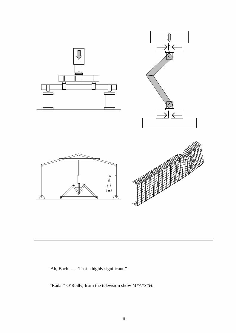
Bending tests were performed on cold-formed RHS to examine the web and flange slenderness
required to maintain the plastic moment for a large enough rotation suitable for plastic design.
The major conclusions of the beam tests were:
(i) Some sections which are classified as Compact or Class 1 by current steel design
specifications do not maintain plastic rotations considered sufficient for plastic design.
(ii) The current design philosophy, in which flange and web slenderness limits are
independent, is inappropriate. An interaction formula is required, and simple formulations
are proposed for RHS.
Connection tests were performed on various types of knee joints in RHS, suitable for the
column - rafter connection in a portal frame. The connection types investigated were welded
stiffened and unstiffened rigid knee connections, bolted plate knee joints, and welded and bolted
internal sleeve knee joints, for use in RHS portal frames. The ability of the connections to act as
plastic hinges in a portal frame was investigated.
The most important finding of the joint tests was the unexpected fracture of the cold-formed
welded connections under opening moment before significant plastic rotations occurred. The use
of an internal sleeve moved the plastic hinge in the connection away from the connection centre-
line thus eliminating the need for the weld between the RHS, or the RHS and the stiffening plate,
to carry the majority of the load. The internal sleeve connections were capable of sustaining the
plastic moment for large rotations considered suitable for plastic design.
Page 4
iv
Tests on pinned-base portal frames were also performed. There were three separate tests, with
two different ratios of vertical to horizontal point loads, simulating gravity and horizontal wind
loads. Two grades of steel were used for comparison. The aims of the tests were to examine if
a plastic collapse mechanism could form in a cold-formed RHS frame, and to investigate if plastic
design was suitable for such frames.
In each frame, two regions of highly concentrated curvature were observed before the onset of
local buckling, which indicated the formation of plastic hinges and a plastic collapse mechanism.
An advanced plastic zone structural analysis which accounted for second order effects, material
non-linearity and member imperfections slightly overestimated the strength of the frames. The
analysis slightly underestimated the deflections, and hence the magnitude of the second order
effects. A second order plastic zone analysis, which did not account for the effects of structural
imperfections, provided the best estimates of the strengths of the frames, but also underestimated
the deflections.
While cold-formed RHS did not satisfy the material ductility requirements specified for plastic
design in some current steel design standards, plastic hinges and plastic collapse mechanisms
formed. This suggests that the restriction on plastic design for cold-formed RHS based on
insufficient material ductility is unnecessary, provided that the connections are suitable for plastic
hinge formation, if required.
A large number of finite element analyses were performed to simulate the bending tests
summarised above, and to examine various parameters not studied in the experimental
investigation. To simulate the experimental rotation capacity of the RHS beams, a sinusoidally
varying longitudinal local imperfection was prescribed. The finite element analysis determined
similar trends as observed experimentally, namely that the rotation capacity depended on both the
web slenderness and flange slenderness, and that for a given section aspect ratio, the relationship
between web slenderness and rotation capacity was non-linear.
The main finding of the finite element study was that the size of the imperfections had an
unexpectedly large influence on the rotation capacity. Larger imperfections were required in the
more slender sections to simulate the experimental results. There should be further investigation
into the effect of varying material properties on rotation capacity.
Page 5
v
PREFACE
This thesis is submitted to The University of Sydney, Sydney, Australia, for the degree of Doctor
of Philosophy. The work described herein was performed by the author in the Department of
Civil Engineering, The University of Sydney. The period of candidature was from February 1995
to July 1999. The author was supervised by Greg Hancock, BHP Steel Professor of Steel
Structures.
Under the Resolutions of the Senate of The University of Sydney relating to the requirements for
the Degree of Doctor of Philosophy, the author declares that the work presented herein is
original, unless referenced otherwise in the text. In particular, the series of tests on cold-formed
RHS beams, connections, and frames, and the finite element analyses of cold-formed RHS beams
are claimed as original.
The following papers, based on the work presented in this thesis, have been jointly written with
Professor Greg Hancock:
Journal Papers
Wilkinson T. and Hancock G. J., (1998), “Tests to examine the compact web slenderness of
cold-formed RHS”, Journal of Structural Engineering, American Society of Civil Engineers,
Vol 124, No 10, October 1998, pp 1166-1174.
Wilkinson T. and Hancock G. J., (2000), “Tests to examine the plastic behavior of knee joints in
cold-formed RHS”, Journal of Structural Engineering, American Society of Civil Engineers,
(scheduled for publication in March 2000).
Conference Papers
Wilkinson T. and Hancock G. J., (1997), “Tests to Investigate the Web Slenderness Limits for
Cold-Formed RHS in Bending”, The Mechanics of Structures and Materials, Proceedings, 15th
Australasian Conference on the Mechanics of Structures and Materials, Melbourne, Australia,
December 1997, (Balkema, publ.), (Grzebieta, Al-Mahaidi & Wilson editors), pp 559-564.
Page 6
vi
Wilkinson T. and Hancock G. J., (1998), “Compact or Class 1 Limits for Rectangular Hollow
Sections in Bending”, Tubular Structures VIII, Proceedings, 8th International Symposium on
Tubular Structures, Singapore, August 1998, (Balkema, publ.), (Choo, Van der Vegte editors),
pp 409-416.
Wilkinson T. and Hancock G. J., (1998), “Tests of Stiffened and Unstiffened Knee Connections
in Cold-Formed RHS”, Tubular Structures VIII, Proceedings, 8th International Symposium on
Tubular Structures, Singapore, August 1998, (Balkema, publ.), (Choo, Van der Vegte editors),
pp 177-186.
Wilkinson T. and Hancock G. J., (1998), “Tests of Bolted and Internal Sleeve Knee Connections
in Cold-Formed RHS”, Tubular Structures VIII, Proceedings, 8th International Symposium on
Tubular Structures, Singapore, August 1998, (Balkema, publ.), (Choo, Van der Vegte editors),
pp 187-195.
Wilkinson T. and Hancock G. J., (1998), “Tests of Portal Frames in Cold-Formed RHS”,
Tubular Structures VIII, Proceedings, 8th International Symposium on Tubular Structures,
Singapore, August 1998, (Balkema, publ.), (Choo, Van der Vegte editors), pp 521-529.
Wilkinson T. and Hancock G. J., (1998), “Plastic Design of Cold-Formed Rectangular Hollow
Sections”, Proceedings of the 5th Pacific Structural Steel Conference, Seoul, Korea, October
1998, (Techno Press, publ.), (Chang, Cho, Yun and Kim, eds.), pp 49 - 54.
Wilkinson T. and Hancock G. J., (1999), “Comparison of Analyses with Tests of Cold-Formed
RHS Portal Frames”, The Mechanics of Structures and Materials, Proceedings, 16th
Australasian Conference on the Mechanics of Structures and Materials, Sydney, Australia,
December 1999, (Balkema, publ.), (Bradford, Bridge and Foster editors), pp 245-250.
Wilkinson T. and Hancock G. J., (1999), “Predictions of Rotation Capacity of RHS Beams Using
Finite Element Analysis”, Advances in Steel Structures, Proceedings, 2 International Conferencend
on Advances in Steel Structures, (ICASS’99), Hong Kong, China, December 1999, (Elsevier,
publ.), (Chan and Teng editors), pp 261 - 268.
Page 7
vii
Research Reports
Wilkinson T. and Hancock G. J., (1997), “Tests for the Compact Web Slenderness of
Cold-Formed Rectangular Hollow Sections”, Research Report, No R744, Department of Civil
Engineering, The University of Sydney, Sydney, Australia.
Wilkinson T. and Hancock G. J., (1998), “Tests of Knee Joints in Cold-Formed Rectangular
Hollow Sections”, Research Report, No R779, Department of Civil Engineering, The University
of Sydney, Sydney, Australia.
Wilkinson T. and Hancock G. J., (1999), “Tests of Cold-Formed Rectangular Hollow Section
Portal Frames”, Research Report, No R783, Department of Civil Engineering, The University of
Sydney, Sydney, Australia
Wilkinson T. and Hancock G. J., (1999), “Finite Element Analysis of Plastic Bending of
Cold-Formed Rectangular Hollow Section Beams”, Research Report, No R792, Department of
Civil Engineering, The University of Sydney, Sydney, Australia.
Reports
The research in this thesis was conducted partly as a research project funded by CIDECT. The
following reports were prepared for CIDECT during the author’s candidature:
Wilkinson T. and Hancock G. J., (1995), “Plastic Design of Cold-Formed RHS”, CIDECT
Project 2S, Interim Report No. 1, Centre for Advanced Structural Engineering, School of Civil
and Mining Engineering, The University of Sydney, Sydney, Australia.
Wilkinson T. and Hancock G. J., (1996), “Plastic Design of Cold-Formed RHS”, CIDECT
Project 2S, Interim Report No. 2, Centre for Advanced Structural Engineering, School of Civil
and Mining Engineering, The University of Sydney, Sydney, Australia.
Page 8
viii
Wilkinson T. and Hancock G. J., (1996), “Plastic Design of Cold-Formed RHS”, CIDECT
Project 2S, Interim Report No. 2: Addendum 1: Joint Tests, Centre for Advanced Structural
Engineering, School of Civil and Mining Engineering, The University of Sydney, Sydney,
Australia.
Wilkinson T. and Hancock G. J., (1997), “Plastic Design of Cold-Formed RHS”, CIDECT
Project 2S, Interim Report No. 3, Centre for Advanced Structural Engineering, Department of
Civil Engineering, The University of Sydney, Sydney, Australia.
Wilkinson T. and Hancock G. J., (1997), “Plastic Design of Cold-Formed RHS”, CIDECT
Project 2S, Interim Report No. 3: Addendum 1: Frame Tests, Centre for Advanced Structural
Engineering, Department of Civil Engineering, The University of Sydney, Sydney, Australia.
Wilkinson T. and Hancock G. J., (1998), “Plastic Design of Cold-Formed RHS”, CIDECT
Project 2S, Draft Final Report, Centre for Advanced Structural Engineering, Department of Civil
Engineering, The University of Sydney, Sydney, Australia.
The author has made some of the above publications available in electronic format via the World
Wide Web page of the Department of Civil Engineering: http://www.civil.usyd.edu.au
The email address of the author is [email protected]
Tim Wilkinson
Department of Civil Engineering
The University of Sydney
Sydney, Australia
July 1999
Page 9
ix
ACKNOWLEDGEMENTS
Completing a PhD is a long and complex task. One can never complete the thesis without the
help and cooperation of a large number of people.
I firstly thank my supervisor, Greg Hancock, for all he has done to assist me during my
candidature. He has provided expert advice and support in that period. He is more than a
supervisor, providing friendship, and encouragement in my career. Having Greg as a supervisor
has made the difficult task of completing this degree much easier. Thanks, Greg.
Thanks to other members of the academic staff, Murray Clarke and Kim Rasmussen, who gave
advice at various stages.
I am indebted to those who provided financial support to this project. My main scholarship was
an Australian Postgraduate Award funded by the Commonwealth of Australia, Department of
Employment, Education, Training and Youth Affairs (in other words, the Australian taxpayers),
supplemented by the Centre for Advanced Structural Engineering, and other sources within the
Department of Civil Engineering. The project itself was funded by CIDECT (Comité
International pour le Developpement et l’Étude de la Construction Tubulaire) - those funds paid
for a technical officer, materials for the research, a computer, and some conference travel. I
appreciate the work of Xiao-Ling Zhao, who was primarily responsible for the original grant
application to CIDECT. Additional monies for conference travels were also provided by Greg
Hancock.
I am most fortunate to have been enrolled in the Department of Civil Engineering, as the support
the department gives postgraduate students helps to make the PhD process a more fruitful one.
The Department has provided items such as Internet and Email access, network printers,
photocopying, and the daily coffee and biscuits: all essential items for a postgrad. I thank the
Head of Department, John Carter, for the Department’s continued support of postgraduate
students.
Page 10
x
The work involved in this research was predominately experimental, and fabricating the numerous
steel members required for all my tests was done in the workshop and J. W. Roderick Laboratory
for Materials and Structures, in the Department of Civil Engineering. I owe much to the efficient
and high quality work of Grant Holgate. Without his help, none of my tests could have been
conducted, and he provided solutions to some of the tricky detailing problems in many of my
drawings. Thanks are also due to other technical staff in the laboratory and workshop: Garry
Towell, Ian Hoggard, Paul Burrell, Craig McCready, Brett Jones, Glenn Cox and Ozzy (Paul
Busstra).
Test specimens were provided by BHP Steel Structural and Pipeline Products.
Modern research is reliant on computers and electronics, and users depend on the support staff
to keep the computers running. I am most grateful to Danny Kim, who helped me with numerous
network problems, and particulary for maintaining the UNIX computer system, while my
numerical analyses were working overtime. Thanks also to Mat Fleming, Phil Witty, and Rex
Barry in the Electronics Workshop whenever my computer broke down. Dan Popovic was
always a fountain of information when it came to computer software. Bernard Gardner and
Didier Debuf also helped maintain the UNIX system of the department.
Thanks to other members of staff, especially Gwenda McJannet, who always knew where
everything was in Greg’s office. Other administrative staff, Cynthia Papangelis, Lynda-Jane
Kiszczak and Tmne Blair also provided assistance. Ron Brew and Kim Pham created some of the
figures in this thesis electronically, and made slides for various presentations during my
candidature.
I have been fortunate to meet many fellow researchers in tubular structures through my
association with CIDECT. I especially thank Hayden Dagg, from BHP Steel Structural and
Pipeline Products, for all his help and for providing the steel specimens. Conversations with
Hayden are always entertaining. Thanks go to others associated with CIDECT who have given
advice: Jeff Packer, Jaap Wardenier, Terry Giddings, Mike Edwards, Noel Yeomans, Yoshiaki
Kurobane, Natalie Stranghoner, Ram Puthli and Stefan Herion (and his daughter Fabi!).
Page 11
xi
Thanks go to those who have provided advice, information, or publications and papers, including:
Ted Galambos, Geoff Kulak, Mahen Mehendran, Arun Syam, Philippe Boeraeve, Frank Mang,
Harry Siedses, Bill Bailey and Gordon Lane (IPSCO), and R. K. Engineering.
I am also grateful to the staff at The University of Sydney Library, who were able to obtain many
old documents. Several references were obtained from the library of the Australian Institute of
Steel Construction.
My candidature has been an enjoyable time, and I have made friends amongst my postgrad
colleagues. Whether they provided direct help with my project, or they were present at the Friday
afternoon drinks, the assistance of my friends made my experience worthwhile. Thanks go to
Peter Hitchcock (“Alfred”) - who endured two overseas trips with me wearing “baggy tight
jeans”, Colin Rogers (“Golden Boy” or “GB”) - who loved the Australian climate and frogs so
much and taught us many Canadian sayings, Catherine Rousch, Martin O’Shea (“MOS”), Andrew
Wheeler (“Mr Cranky”), Cameron Chick, Dan Popovic (“Poppy”), Graeme Wood (“Brucie”),
Roy Denoon, Ben Young, Anthony Hasham (“Eric”), Lip Teh, Mike Bambach (“Leopard Boy”
or “LB”), Pat Kelleher, Gustav Spener (“Goodstuff”), Martijn van Kaam (“Joe”), Per Granath,
Judith Massonne, Sukit Thepmongkorn (“Tommy”), Bogdan Put, Raef Sully, Axel Volkwein and
Jan Torka.
It saddens me that my father, Jeff Wilkinson, will never see this thesis, as he passed away during
my candidature. While he may not have understood the fine details, he would surely have read
it, remembered it, and found any spelling or grammatical errors. He also would have been pleased
that we finally have a “proper” doctor in the family. I thank my father and mother, Joan
Wilkinson, who provided me with the upbringing that has enabled me to complete this thesis.
Tim Wilkinson
July 1999
Page 12
xii
CONTENTS
SYNOPSIS . . . . . . . . . . . . . . . . . . . . . . . . . . . . . . . . . . . . . . . . . . . . . . . . . . . . . . iii
PREFACE . . . . . . . . . . . . . . . . . . . . . . . . . . . . . . . . . . . . . . . . . . . . . . . . . . . . . . . . v
ACKNOWLEDGEMENTS . . . . . . . . . . . . . . . . . . . . . . . . . . . . . . . . . . . . . . . . . . ix
CONTENTS . . . . . . . . . . . . . . . . . . . . . . . . . . . . . . . . . . . . . . . . . . . . . . . . . . . . . xii
NOTATION . . . . . . . . . . . . . . . . . . . . . . . . . . . . . . . . . . . . . . . . . . . . . . . . . . . . . xx
1 INTRODUCTION . . . . . . . . . . . . . . . . . . . . . . . . . . . . . . . . . . . . . . . . . . . . . . . . . 1
1.1 Background . . . . . . . . . . . . . . . . . . . . . . . . . . . . . . . . . . . . . . . . . . . . . . . . . . . . . . . 1
1.2 Aim of the Thesis . . . . . . . . . . . . . . . . . . . . . . . . . . . . . . . . . . . . . . . . . . . . . . . . . . . 3
1.3 Outline of the Thesis . . . . . . . . . . . . . . . . . . . . . . . . . . . . . . . . . . . . . . . . . . . . . . . . 4
1.3.1 General . . . . . . . . . . . . . . . . . . . . . . . . . . . . . . . . . . . . . . . . . . . . . . . . . . . . . 4
1.3.2 Experimental Investigations . . . . . . . . . . . . . . . . . . . . . . . . . . . . . . . . . . . . . 4
1.3.3 Numerical (Finite Element) Analysis . . . . . . . . . . . . . . . . . . . . . . . . . . . . . . . 7
1.3.4 Comparison with Design Specifications . . . . . . . . . . . . . . . . . . . . . . . . . . . . 8
2 INTRODUCTION TO PLASTIC DESIGN, LITERATURE REVIEW, AND
CURRENT DESIGN STANDARDS . . . . . . . . . . . . . . . . . . . . . . . . . . . . . . . . . . 10
2.0 Chapter Synopsis . . . . . . . . . . . . . . . . . . . . . . . . . . . . . . . . . . . . . . . . . . . . . . . . . . 10
2.1 Cold-Formed Hollow Sections . . . . . . . . . . . . . . . . . . . . . . . . . . . . . . . . . . . . . . . . 10
2.2 Basics of Plastic Design . . . . . . . . . . . . . . . . . . . . . . . . . . . . . . . . . . . . . . . . . . . . . 13
2.2.1 Bending Behaviour of Structural Steel Beams and the Plastic Hinge . . . . . . 13
2.2.2 Rotation Capacity and Classification of Sections . . . . . . . . . . . . . . . . . . . . . 16
2.2.3 The Behaviour of a Simply Supported Beam. . . . . . . . . . . . . . . . . . . . . . . . 19
2.2.4 Basic Plastic Analysis . . . . . . . . . . . . . . . . . . . . . . . . . . . . . . . . . . . . . . . . . 21
2.2.4.1 Built-In Beam . . . . . . . . . . . . . . . . . . . . . . . . . . . . . . . . . . . 21
2.2.4.2 Simple Portal Frame . . . . . . . . . . . . . . . . . . . . . . . . . . . . . . 23
2.2.5 Rotation Requirements . . . . . . . . . . . . . . . . . . . . . . . . . . . . . . . . . . . . . . . . 24
2.3 Research into the Plastic Behaviour of Steel . . . . . . . . . . . . . . . . . . . . . . . . . . . . . . 26
Page 13
xiii
2.4 Local Buckling and Slenderness Limits . . . . . . . . . . . . . . . . . . . . . . . . . . . . . . . . . . 30
2.4.1 Elastic Local Buckling of Thin Rectangular Plates . . . . . . . . . . . . . . . . . . . 30
2.4.2 Definition of Slenderness . . . . . . . . . . . . . . . . . . . . . . . . . . . . . . . . . . . . . . 33
2.4.3 Elements in Compression Supported on One Edge. . . . . . . . . . . . . . . . . . . 35
2.4.4 Elements in Compression Supported on Both Edges. . . . . . . . . . . . . . . . . . 37
2.4.5 Elements in Bending Supported on Both Edges. . . . . . . . . . . . . . . . . . . . . 40
2.4.6 Elements in Bending and Compression Supported on Both Edges. . . . . . . . 49
2.4.7 Interaction Effects in Local Buckling . . . . . . . . . . . . . . . . . . . . . . . . . . . . . 55
2.5 Material Properties in Plastic Design . . . . . . . . . . . . . . . . . . . . . . . . . . . . . . . . . . . 57
2.6 Knee Joints in Portal Frames . . . . . . . . . . . . . . . . . . . . . . . . . . . . . . . . . . . . . . . . . 60
2.7 Research by CIDECT . . . . . . . . . . . . . . . . . . . . . . . . . . . . . . . . . . . . . . . . . . . . . . . 66
2.8 Research at The University of Sydney . . . . . . . . . . . . . . . . . . . . . . . . . . . . . . . . . . 66
2.9 Summary . . . . . . . . . . . . . . . . . . . . . . . . . . . . . . . . . . . . . . . . . . . . . . . . . . . . . . . . 67
3 BENDING TESTS OF COLD-FORMED RECTANGULAR HOLLOW
SECTIONS . . . . . . . . . . . . . . . . . . . . . . . . . . . . . . . . . . . . . . . . . . . . . . . . . . . . . . 70
3.0 Chapter Synopsis . . . . . . . . . . . . . . . . . . . . . . . . . . . . . . . . . . . . . . . . . . . . . . . . . . 70
3.1 Introduction . . . . . . . . . . . . . . . . . . . . . . . . . . . . . . . . . . . . . . . . . . . . . . . . . . . . . . 71
3.2 Test Specimens and Material Properties . . . . . . . . . . . . . . . . . . . . . . . . . . . . . . . . . 72
3.2.1 RHS Properties . . . . . . . . . . . . . . . . . . . . . . . . . . . . . . . . . . . . . . . . . . . . . 72
3.2.2 Tensile Coupon Tests . . . . . . . . . . . . . . . . . . . . . . . . . . . . . . . . . . . . . . . . . 73
3.2.3 Full Section Tensile Tests . . . . . . . . . . . . . . . . . . . . . . . . . . . . . . . . . . . . . . 75
3.2.4 Stub Column Tests . . . . . . . . . . . . . . . . . . . . . . . . . . . . . . . . . . . . . . . . . . . 75
3.2.5 Geometric Imperfections . . . . . . . . . . . . . . . . . . . . . . . . . . . . . . . . . . . . . . 76
3.3 Bending Test Procedure . . . . . . . . . . . . . . . . . . . . . . . . . . . . . . . . . . . . . . . . . . . . . 77
3.4 Results . . . . . . . . . . . . . . . . . . . . . . . . . . . . . . . . . . . . . . . . . . . . . . . . . . . . . . . . . . 82
3.5 Discussion . . . . . . . . . . . . . . . . . . . . . . . . . . . . . . . . . . . . . . . . . . . . . . . . . . . . . . . 90
3.6 Bending Tests of Hot-Formed RHS . . . . . . . . . . . . . . . . . . . . . . . . . . . . . . . . . . . . 99
3.7 Conclusions . . . . . . . . . . . . . . . . . . . . . . . . . . . . . . . . . . . . . . . . . . . . . . . . . . . . . 100
3.7.1 Summary . . . . . . . . . . . . . . . . . . . . . . . . . . . . . . . . . . . . . . . . . . . . . . . . . 100
3.7.2 Further Study . . . . . . . . . . . . . . . . . . . . . . . . . . . . . . . . . . . . . . . . . . . . . . 100
Page 14
xiv
4 TESTS OF KNEE JOINTS IN COLD-FORMED RECTANGULAR
HOLLOW SECTIONS . . . . . . . . . . . . . . . . . . . . . . . . . . . . . . . . . . . . . . . . . . . 103
4.0 Chapter Synopsis . . . . . . . . . . . . . . . . . . . . . . . . . . . . . . . . . . . . . . . . . . . . . . . . . 103
4.1 Introduction . . . . . . . . . . . . . . . . . . . . . . . . . . . . . . . . . . . . . . . . . . . . . . . . . . . . . 104
4.2 Test Program . . . . . . . . . . . . . . . . . . . . . . . . . . . . . . . . . . . . . . . . . . . . . . . . . . . . 105
4.2.1 Material Properties . . . . . . . . . . . . . . . . . . . . . . . . . . . . . . . . . . . . . . . . . . 105
4.2.1.1 RHS Properties . . . . . . . . . . . . . . . . . . . . . . . . . . . . . . . . . 105
4.2.1.2 Tensile Coupon Tests . . . . . . . . . . . . . . . . . . . . . . . . . . . . 106
4.2.1.3 Plate Properties . . . . . . . . . . . . . . . . . . . . . . . . . . . . . . . . . 107
4.2.1.4 Bolt Properties . . . . . . . . . . . . . . . . . . . . . . . . . . . . . . . . . 107
4.2.2 Connection Details . . . . . . . . . . . . . . . . . . . . . . . . . . . . . . . . . . . . . . . . . . 108
4.2.2.1 Stiffened Welded Connection . . . . . . . . . . . . . . . . . . . . . . 108
4.2.2.2 Unstiffened Welded Connection . . . . . . . . . . . . . . . . . . . . . 109
4.2.2.3 Bolted End Plate . . . . . . . . . . . . . . . . . . . . . . . . . . . . . . . . 110
4.2.2.4 Welded Internal Sleeve . . . . . . . . . . . . . . . . . . . . . . . . . . . 112
4.2.2.5 Bolted Internal Sleeve . . . . . . . . . . . . . . . . . . . . . . . . . . . . 113
4.2.3 Welding Procedures . . . . . . . . . . . . . . . . . . . . . . . . . . . . . . . . . . . . . . . . . 113
4.2.4 Test Procedure . . . . . . . . . . . . . . . . . . . . . . . . . . . . . . . . . . . . . . . . . . . . . 115
4.2.5 Tests of Bolted Moment End Plate Connections . . . . . . . . . . . . . . . . . . . . 119
4.3 Results . . . . . . . . . . . . . . . . . . . . . . . . . . . . . . . . . . . . . . . . . . . . . . . . . . . . . . . . . 119
4.3.1 General . . . . . . . . . . . . . . . . . . . . . . . . . . . . . . . . . . . . . . . . . . . . . . . . . . . 119
4.3.2 Failure Modes . . . . . . . . . . . . . . . . . . . . . . . . . . . . . . . . . . . . . . . . . . . . . 123
4.3.3 Load - Stroke Curves . . . . . . . . . . . . . . . . . . . . . . . . . . . . . . . . . . . . . . . . 125
4.3.4 Moment - Curvature Curves . . . . . . . . . . . . . . . . . . . . . . . . . . . . . . . . . . . 127
4.3.5 Moment - Rotation Curves . . . . . . . . . . . . . . . . . . . . . . . . . . . . . . . . . . . . 129
4.4 Discussion . . . . . . . . . . . . . . . . . . . . . . . . . . . . . . . . . . . . . . . . . . . . . . . . . . . . . . 133
4.4.1 Stiffened and Unstiffened Welded Joints . . . . . . . . . . . . . . . . . . . . . . . . . . 133
4.4.2 Bolted Plate and Internal Sleeve Knee Connections . . . . . . . . . . . . . . . . . 139
4.5 Conclusions . . . . . . . . . . . . . . . . . . . . . . . . . . . . . . . . . . . . . . . . . . . . . . . . . . . . . 142
4.5.1 Summary . . . . . . . . . . . . . . . . . . . . . . . . . . . . . . . . . . . . . . . . . . . . . . . . . 142
4.5.2 Further Study . . . . . . . . . . . . . . . . . . . . . . . . . . . . . . . . . . . . . . . . . . . . . . 143
Page 15
xv
5 TESTS OF COLD-FORMED RHS PORTAL FRAMES . . . . . . . . . . . . . . . . 146
5.0 Chapter Synopsis . . . . . . . . . . . . . . . . . . . . . . . . . . . . . . . . . . . . . . . . . . . . . . . . . 146
5.1 Introduction . . . . . . . . . . . . . . . . . . . . . . . . . . . . . . . . . . . . . . . . . . . . . . . . . . . . . 147
5.2 Material Properties . . . . . . . . . . . . . . . . . . . . . . . . . . . . . . . . . . . . . . . . . . . . . . . . 148
5.2.1 Section Selection . . . . . . . . . . . . . . . . . . . . . . . . . . . . . . . . . . . . . . . . . . . 148
5.2.2 Tensile Coupon Tests . . . . . . . . . . . . . . . . . . . . . . . . . . . . . . . . . . . . . . . . 148
5.2.3 Plastic Bending Tests . . . . . . . . . . . . . . . . . . . . . . . . . . . . . . . . . . . . . . . . 149
5.2.4 Connection Tests . . . . . . . . . . . . . . . . . . . . . . . . . . . . . . . . . . . . . . . . . . . 149
5.2.5 Welding Procedures . . . . . . . . . . . . . . . . . . . . . . . . . . . . . . . . . . . . . . . . . 150
5.3 Portal Frame Details . . . . . . . . . . . . . . . . . . . . . . . . . . . . . . . . . . . . . . . . . . . . . . . 151
5.3.1 General Details and Nominal Dimensions . . . . . . . . . . . . . . . . . . . . . . . . . 151
5.3.2 Connections . . . . . . . . . . . . . . . . . . . . . . . . . . . . . . . . . . . . . . . . . . . . . . . 155
5.3.2.1 Knee Joint . . . . . . . . . . . . . . . . . . . . . . . . . . . . . . . . . . . . . 155
5.3.2.2 Apex Joint . . . . . . . . . . . . . . . . . . . . . . . . . . . . . . . . . . . . . 157
5.3.2.3 Base . . . . . . . . . . . . . . . . . . . . . . . . . . . . . . . . . . . . . . . . . 159
5.3.2.4 Channel Collar Tie . . . . . . . . . . . . . . . . . . . . . . . . . . . . . . . 160
5.3.3 Lateral Restraints . . . . . . . . . . . . . . . . . . . . . . . . . . . . . . . . . . . . . . . . . . . 161
5.3.4 Construction Sequence . . . . . . . . . . . . . . . . . . . . . . . . . . . . . . . . . . . . . . . 165
5.4 Test Procedure . . . . . . . . . . . . . . . . . . . . . . . . . . . . . . . . . . . . . . . . . . . . . . . . . . . 166
5.4.1 Instrumentation . . . . . . . . . . . . . . . . . . . . . . . . . . . . . . . . . . . . . . . . . . . . 166
5.4.2 Dimensions and Imperfection Measurements . . . . . . . . . . . . . . . . . . . . . . . 168
5.4.3 Loading Method . . . . . . . . . . . . . . . . . . . . . . . . . . . . . . . . . . . . . . . . . . . . 171
5.4.4 Loading Procedure . . . . . . . . . . . . . . . . . . . . . . . . . . . . . . . . . . . . . . . . . . 175
5.5 Results . . . . . . . . . . . . . . . . . . . . . . . . . . . . . . . . . . . . . . . . . . . . . . . . . . . . . . . . . 176
5.5.1 Observations . . . . . . . . . . . . . . . . . . . . . . . . . . . . . . . . . . . . . . . . . . . . . . 176
5.5.2 Ultimate Loads and Load Deflection Curves . . . . . . . . . . . . . . . . . . . . . . . 178
5.5.3 Curvature . . . . . . . . . . . . . . . . . . . . . . . . . . . . . . . . . . . . . . . . . . . . . . . . 181
5.5.4 Ductility . . . . . . . . . . . . . . . . . . . . . . . . . . . . . . . . . . . . . . . . . . . . . . . . . . 186
5.5.5 Serviceability and Deflections. . . . . . . . . . . . . . . . . . . . . . . . . . . . . . . . . . 187
5.5.5.1 The Serviceability Limit State . . . . . . . . . . . . . . . . . . . . . . 187
5.5.5.2 Deflection Limits. . . . . . . . . . . . . . . . . . . . . . . . . . . . . . . . 188
5.5.5.3 Experimental Deflections . . . . . . . . . . . . . . . . . . . . . . . . . . 189
5.5.5.4 Serviceability Discussion . . . . . . . . . . . . . . . . . . . . . . . . . . 192
Page 16
xvi
5.6 Comparison with Methods of Analysis . . . . . . . . . . . . . . . . . . . . . . . . . . . . . . . . . 194
5.6.1 First Order Elastic Analysis . . . . . . . . . . . . . . . . . . . . . . . . . . . . . . . . . . . . 194
5.6.2 Second Order Elastic Analysis . . . . . . . . . . . . . . . . . . . . . . . . . . . . . . . . . 197
5.6.3 Simple Plastic Analysis . . . . . . . . . . . . . . . . . . . . . . . . . . . . . . . . . . . . . . . 197
5.6.4 Plastic Zone Analysis . . . . . . . . . . . . . . . . . . . . . . . . . . . . . . . . . . . . . . . . 199
5.6.5 Comparison and Discussion . . . . . . . . . . . . . . . . . . . . . . . . . . . . . . . . . . . 200
5.6.5.1 Elastic Response . . . . . . . . . . . . . . . . . . . . . . . . . . . . . . . . 205
5.6.5.2 Plastic Analysis . . . . . . . . . . . . . . . . . . . . . . . . . . . . . . . . . 205
5.6.5.3 Interaction of Bending Moment and Axial Force . . . . . . . . 207
5.6.5.4 Second Order Effects . . . . . . . . . . . . . . . . . . . . . . . . . . . . 208
5.6.5.5 Material Non-Linearity and Strain Hardening . . . . . . . . . . . 208
5.6.5.6 Imperfections . . . . . . . . . . . . . . . . . . . . . . . . . . . . . . . . . . 209
5.6.5.7 Joint Flexibility . . . . . . . . . . . . . . . . . . . . . . . . . . . . . . . . . 211
5.6.5.8 Summary . . . . . . . . . . . . . . . . . . . . . . . . . . . . . . . . . . . . . . 212
5.7 Conclusions . . . . . . . . . . . . . . . . . . . . . . . . . . . . . . . . . . . . . . . . . . . . . . . . . . . . . 213
5.7.1 Summary . . . . . . . . . . . . . . . . . . . . . . . . . . . . . . . . . . . . . . . . . . . . . . . . . 213
5.7.2 Further Study . . . . . . . . . . . . . . . . . . . . . . . . . . . . . . . . . . . . . . . . . . . . . . 214
6 FINITE ELEMENT ANALYSIS OF COLD-FORMED RHS BEAMS . . . . . 217
6.0 Chapter Synopsis . . . . . . . . . . . . . . . . . . . . . . . . . . . . . . . . . . . . . . . . . . . . . . . . . 217
6.1 Introduction . . . . . . . . . . . . . . . . . . . . . . . . . . . . . . . . . . . . . . . . . . . . . . . . . . . . . 218
6.2 Development of the Finite Element Model . . . . . . . . . . . . . . . . . . . . . . . . . . . . . . 219
6.2.1 Physical Model . . . . . . . . . . . . . . . . . . . . . . . . . . . . . . . . . . . . . . . . . . . . . 219
6.2.2 Symmetry and Boundary Conditions . . . . . . . . . . . . . . . . . . . . . . . . . . . . . 220
6.2.3 Choice of Element Type . . . . . . . . . . . . . . . . . . . . . . . . . . . . . . . . . . . . . . 223
6.2.4 Loading . . . . . . . . . . . . . . . . . . . . . . . . . . . . . . . . . . . . . . . . . . . . . . . . . . 225
6.2.5 Pre and Post Processing . . . . . . . . . . . . . . . . . . . . . . . . . . . . . . . . . . . . . . 227
6.2.6 Material Properties . . . . . . . . . . . . . . . . . . . . . . . . . . . . . . . . . . . . . . . . . . 229
6.2.7 Residual Stresses . . . . . . . . . . . . . . . . . . . . . . . . . . . . . . . . . . . . . . . . . . . 232
6.2.8 Mesh Refinement . . . . . . . . . . . . . . . . . . . . . . . . . . . . . . . . . . . . . . . . . . . 233
Page 17
xvii
6.2.9 Geometric Imperfections . . . . . . . . . . . . . . . . . . . . . . . . . . . . . . . . . . . . . 235
6.2.9.1 “Bow-out” Imperfections . . . . . . . . . . . . . . . . . . . . . . . . . 235
6.2.9.2 Continuous Sinusoidal Imperfection . . . . . . . . . . . . . . . . . 239
6.2.9.3 Single Sinusoidal Imperfection . . . . . . . . . . . . . . . . . . . . . . 244
6.2.9.4 Comparing Rotation Capacities . . . . . . . . . . . . . . . . . . . . . 246
6.2.9.5 Imperfection Size . . . . . . . . . . . . . . . . . . . . . . . . . . . . . . . 247
6.2.9.6 Effect of Scale Factor . . . . . . . . . . . . . . . . . . . . . . . . . . . . 256
6.2.9.7 Effect of Steel Grade . . . . . . . . . . . . . . . . . . . . . . . . . . . . . 257
6.3 Simulation of the Bending Tests . . . . . . . . . . . . . . . . . . . . . . . . . . . . . . . . . . . . . . 262
6.3.1 General . . . . . . . . . . . . . . . . . . . . . . . . . . . . . . . . . . . . . . . . . . . . . . . . . . . 262
6.3.2 Results . . . . . . . . . . . . . . . . . . . . . . . . . . . . . . . . . . . . . . . . . . . . . . . . . . . 262
6.3.3 Discussion . . . . . . . . . . . . . . . . . . . . . . . . . . . . . . . . . . . . . . . . . . . . . . . . 267
6.4 Parametric Study . . . . . . . . . . . . . . . . . . . . . . . . . . . . . . . . . . . . . . . . . . . . . . . . . 269
6.5 Conclusions . . . . . . . . . . . . . . . . . . . . . . . . . . . . . . . . . . . . . . . . . . . . . . . . . . . . . 270
6.5.1 Summary . . . . . . . . . . . . . . . . . . . . . . . . . . . . . . . . . . . . . . . . . . . . . . . . . 270
6.5.2 Further Study . . . . . . . . . . . . . . . . . . . . . . . . . . . . . . . . . . . . . . . . . . . . . . 271
7 CONCLUSIONS . . . . . . . . . . . . . . . . . . . . . . . . . . . . . . . . . . . . . . . . . . . . . . . . 274
7.1 General . . . . . . . . . . . . . . . . . . . . . . . . . . . . . . . . . . . . . . . . . . . . . . . . . . . . . . . . 274
7.2 Literature Review . . . . . . . . . . . . . . . . . . . . . . . . . . . . . . . . . . . . . . . . . . . . . . . . 275
7.3 Bending Tests of Cold-Formed RHS Beams . . . . . . . . . . . . . . . . . . . . . . . . . . . . . 275
7.4 Portal Frame Knee Connection Tests . . . . . . . . . . . . . . . . . . . . . . . . . . . . . . . . . . 276
7.5 Tests of Portal Frames . . . . . . . . . . . . . . . . . . . . . . . . . . . . . . . . . . . . . . . . . . . . . 277
7.6 Finite Element Analysis . . . . . . . . . . . . . . . . . . . . . . . . . . . . . . . . . . . . . . . . . . . . 278
7.7 Further Study . . . . . . . . . . . . . . . . . . . . . . . . . . . . . . . . . . . . . . . . . . . . . . . . . . . . 280
8 REFERENCES . . . . . . . . . . . . . . . . . . . . . . . . . . . . . . . . . . . . . . . . . . . . . . . . . 284
Page 18
xviii
APPENDICES . . . . . . . . . . . . . . . . . . . . . . . . . . . . . . . . . . . . . . . . . . . . . . . . . . . . . . . . 306
Appendix A Plastic Bending Tests: Moment - Curvature Graphs . . . . . . . . . . . . . . . . . 307
Appendix B Tests of Hot-Formed Rectangular Hollow Sections . . . . . . . . . . . . . . . . . 315
B.1 Introduction . . . . . . . . . . . . . . . . . . . . . . . . . . . . . . . . . . . . . . . . . . . . . . . 315
B.2 Bending Test Procedure . . . . . . . . . . . . . . . . . . . . . . . . . . . . . . . . . . . . . . 316
B.3 Results . . . . . . . . . . . . . . . . . . . . . . . . . . . . . . . . . . . . . . . . . . . . . . . . . . . 316
B.4 Discussion . . . . . . . . . . . . . . . . . . . . . . . . . . . . . . . . . . . . . . . . . . . . . . . . 318
Appendix C Tensile Coupon Tests and Stress - Strain Curves . . . . . . . . . . . . . . . . . . . 323
C.1 Procedure . . . . . . . . . . . . . . . . . . . . . . . . . . . . . . . . . . . . . . . . . . . . . . . . . 323
C.2 Results . . . . . . . . . . . . . . . . . . . . . . . . . . . . . . . . . . . . . . . . . . . . . . . . . . . 324
Appendix D Full Section Tensile Tests . . . . . . . . . . . . . . . . . . . . . . . . . . . . . . . . . . . . . 343
D.1 Introduction . . . . . . . . . . . . . . . . . . . . . . . . . . . . . . . . . . . . . . . . . . . . . . . 343
D.2 Test Program . . . . . . . . . . . . . . . . . . . . . . . . . . . . . . . . . . . . . . . . . . . . . . 344
D.2.1 Test Specimens . . . . . . . . . . . . . . . . . . . . . . . . . . . . . . . . . . . . . . . 344
D.2.2 Tensile Coupon Tests . . . . . . . . . . . . . . . . . . . . . . . . . . . . . . . . . . 345
D.2.3 Full Section Tensile Test Procedure . . . . . . . . . . . . . . . . . . . . . . . 346
D.2.4 Full Section Tensile Test Results . . . . . . . . . . . . . . . . . . . . . . . . . . 347
D.3 Comparison of Different Methods . . . . . . . . . . . . . . . . . . . . . . . . . . . . . . . 349
D.3.1 Methods of Determining Yield Stress . . . . . . . . . . . . . . . . . . . . . . 350
D.3.2 Discussion . . . . . . . . . . . . . . . . . . . . . . . . . . . . . . . . . . . . . . . . . . 351
Appendix E Stub Column Tests . . . . . . . . . . . . . . . . . . . . . . . . . . . . . . . . . . . . . . . . . . 354
E.1 Procedure . . . . . . . . . . . . . . . . . . . . . . . . . . . . . . . . . . . . . . . . . . . . . . . . . 354
E.2 Results . . . . . . . . . . . . . . . . . . . . . . . . . . . . . . . . . . . . . . . . . . . . . . . . . . . 355
E.3 Discussion . . . . . . . . . . . . . . . . . . . . . . . . . . . . . . . . . . . . . . . . . . . . . . . . 358
Appendix F Imperfection Measurements . . . . . . . . . . . . . . . . . . . . . . . . . . . . . . . . . . . 367
F.1 Introduction . . . . . . . . . . . . . . . . . . . . . . . . . . . . . . . . . . . . . . . . . . . . . . . 367
F.2 Method . . . . . . . . . . . . . . . . . . . . . . . . . . . . . . . . . . . . . . . . . . . . . . . . . . 367
F.2.1 Final Method . . . . . . . . . . . . . . . . . . . . . . . . . . . . . . . . . . . . . . . . 367
F.2.2 Initial Method . . . . . . . . . . . . . . . . . . . . . . . . . . . . . . . . . . . . . . . . 368
F.3 Results . . . . . . . . . . . . . . . . . . . . . . . . . . . . . . . . . . . . . . . . . . . . . . . . . . . 370
Appendix G Welding Procedures . . . . . . . . . . . . . . . . . . . . . . . . . . . . . . . . . . . . . . . . . 385
Page 19
xix
Appendix H Tests of Bolted Moment End Plates Connections . . . . . . . . . . . . . . . . . . . 403
H.1 Introduction . . . . . . . . . . . . . . . . . . . . . . . . . . . . . . . . . . . . . . . . . . . . . . . 403
H.2 Connection Details . . . . . . . . . . . . . . . . . . . . . . . . . . . . . . . . . . . . . . . . . . 403
H.3 Test Procedure . . . . . . . . . . . . . . . . . . . . . . . . . . . . . . . . . . . . . . . . . . . . . 404
H.4 Results . . . . . . . . . . . . . . . . . . . . . . . . . . . . . . . . . . . . . . . . . . . . . . . . . . . 406
H.5 Discussion . . . . . . . . . . . . . . . . . . . . . . . . . . . . . . . . . . . . . . . . . . . . . . . . 409
Appendix I Photographs . . . . . . . . . . . . . . . . . . . . . . . . . . . . . . . . . . . . . . . . . . . . . . . 411
Appendix J Parametric Study in the Finite Element Analysis of RHS Beams . . . . . . . . 427
J.1 Introduction . . . . . . . . . . . . . . . . . . . . . . . . . . . . . . . . . . . . . . . . . . . . . . . 427
J.2 Effect of Yield Stress . . . . . . . . . . . . . . . . . . . . . . . . . . . . . . . . . . . . . . . . 428
J.3 Effect of Strain Hardening and Plastic Plateau . . . . . . . . . . . . . . . . . . . . . 434
J.4 Effect of Corner Radius . . . . . . . . . . . . . . . . . . . . . . . . . . . . . . . . . . . . . . 439
J.5 Effect of Beam Length . . . . . . . . . . . . . . . . . . . . . . . . . . . . . . . . . . . . . . . 443
J.6 Effect of Welding . . . . . . . . . . . . . . . . . . . . . . . . . . . . . . . . . . . . . . . . . . . 446
J.6.1 Introduction . . . . . . . . . . . . . . . . . . . . . . . . . . . . . . . . . . . . . . . . . 446
J.6.2 ABAQUS Procedure . . . . . . . . . . . . . . . . . . . . . . . . . . . . . . . . . . . 446
J.6.3 Imperfections Induced . . . . . . . . . . . . . . . . . . . . . . . . . . . . . . . . . . 447
J.6.4 Results . . . . . . . . . . . . . . . . . . . . . . . . . . . . . . . . . . . . . . . . . . . . . 448
J.6.5 Discussion . . . . . . . . . . . . . . . . . . . . . . . . . . . . . . . . . . . . . . . . . . 450
J.7 Conclusion . . . . . . . . . . . . . . . . . . . . . . . . . . . . . . . . . . . . . . . . . . . . . . . . 451
Appendix K Vita . . . . . . . . . . . . . . . . . . . . . . . . . . . . . . . . . . . . . . . . . . . . . . . . . . . . . 454
Page 20
5.65 So
xx
NOTATION
The following symbols are used in this thesis, and are defined where they first appear in the text.
Some symbols have been assigned more than one meaning, but it will be evident from the context
which definition applies.
A Gross cross section areag
a, b, c, d, e, f, g, h, i, j Symbols to define imperfections in the portal frames
b Width of RHS, or width of plate
b Mid-thickness definition of flange widthii
b Clear width definition of flange widthiii
b Flat width definition of flange widthiv
d Depth of RHS
d Mid-thickness definition of web depthii
d Clear width definition of web depthiii
d Flat width definition of web depthiv
E Young’s modulus of elasticity
E Nominal Young’s modulus of elasticityn
E Strain hardening modulusst
e Eccentricity
e Reduced eccentricity1
e Engineering straineng
e Strain over a gauge length of f
e Log plastic strainlnpl
e Strain at which ultimate tensile strength (f ) occursu u
e Yield strainy
e Strain over 2 inch (50.8 mm) gauge length50
f Allowable stressa
f Elastic local buckling stresso
f Ultimate tensile strengthu
f Ultimate tensile strength of the original stripub
f Nominal ultimate tensile strengthun
f Ultimate tensile stress of welduw
Page 21
xxi
f Stress acting on a platex
f Yield stressy
f Yield stress of the original stripyb
f Nominal yield stressyn
f* Allowable stress ratio (= f /f )a y
G Dead load
H Horizontal load
H Constant
h Height
h Height of column
I Second moment of area
k Elastic plate buckling coefficient
k Constant to determine the yield stress enhancement in the corners of RHS
L Length
L Bracing lengthb
L Half-wavelength of local imperfectionw
L Length between loading plates1
L Length between supports2
l Length
M Bending moment
M* Design bending moment
M Design moment resistance of a cross-sectionc,Rd
M Maximum bending momentmax
M Plastic bending momentp
M Nominal plastic bending momentpn
M Design section moment capacityri
M Nominal section moment capacitys
M Bending moment at first yieldy
N Axial force
N* Design axial force (tension or compression)
N Design compression resistance of a cross-sectionc,Rd
N Maximum axial force in connectionmax
N Design section capacity (tension or compression)ri
Page 22
xxii
N Design tension resistance of a cross-sectiont,Rd
N Maximum axial loadmax
N Nominal axial section capacitys
N Nominal axial section capacity (tension)t
N Yield load (= A f )y g y
n Axial load ratio (= N/N )y
n Number of 90E bends in a section of internal radius # 5t
n Number of elements in corner (finite element model of an RHS)elc
n Number of elements in flange (finite element model of an RHS)elf
n Number of elements along the beam length (finite element model of an RHS)els
n Number of elements in web (finite element model of an RHS)elw
P Load
P Maximum loadmax
P Load to induce plastic momentp
P Ultimate loadu
Q Live load
R Rotation capacity
R Rotation capacity based on 97.5 % of the maximum moment97.5
R Rotation capacity based on deflectiondefl
R Rotation capacity based on strain gauge curvaturegauge
R Rotation capacity based on rotation"
r Radius of curvature of a beam
r External corner radius of RHSe
S Plastic section modulus
S Shape factor
S Original cross sectional area of tensile coupono
s Span
t Thickness of RHS, or thickness of plate
u Displacement in 1-axis direction (finite element model)1
u Displacement in 2-axis direction (finite element model)2
u Displacement in 3-axis direction (finite element model)3
V Vertical load
V* Design shear force
Page 23
"̄
"̄1
"̄f
xxiii
V Vertical load at ultimateu
V Vertical load at which deflection limit of s/250 is reacheds/250
V Ultimate vertical loadu
V Maximum shear forcemax
V Plastic shear capacityp
w Out-of-plane deflections of a plate
y Difference in deflection between two points
Z Elastic section modulus
" Proportion of web in compression
" Strain hardening parameter (= E /E)st
" Undeformed connection angle0
" Connection angle at any loadd
" Stress reduction factor for knee jointsknee
" Connection angle at plastic load Pp p
Non-dimensional rotation
Non-dimensional rotation when moment drops below M (compression)p
Non-dimensional rotation at fracture (tension)
$ Moment ratio
* Bow-out imperfection
* Bow-out imperfection of the flangef
* Bow-out imperfection of the webw
* Relative horizontal displacement between adjacent frames at eaves levelh, rel
* Horizontal displacement at 33% of the ultimate loadh, 33%
* Horizontal displacement at 66% of the ultimate loadh, 66%
* Vertical displacement at 66% of the ultimate loadv, 66%
. Parameter to describe length of plastic plateau
2 Angle
2 Hinge rotation angleA
2 Rotation about 1-axis (finite element model)1
2 Rotation about 2-axis (finite element model)2
2 Rotation about 3-axis (finite element model)3
6 Curvature
6 Curvature at bucklingb
Page 24
xxiv
6 Curvature at fracturef
6 Plastic curvature (= M /EI)p p
6 Curvature at which the moment falls below M1 p
6 Curvature when the moment drops below 97.5 % of the maximum moment97.5
R Load factors
8 Flange slendernessf
8 Web slendernessw
8 Web slenderness limit reduced in presence of axial compressionwr
< Poisson’s ratio
B Pi
N Capacity reduction factor
M Partial derivative


![[CIDECT DG3] -- Design Guide for Rectangular Hollow Section (RHS) Joints Under Predominantly Static Loading](https://static.documents.pub/doc/80x56/577d210a1a28ab4e1e94553f/cidect-dg3-design-guide-for-rectangular-hollow-section-rhs-joints-under.jpg)


