THE POWER OF COMMUNICATION: ENERGY-EFFICIENT NOCS FOR FPGAS Mohamed S. Abdelfattah and Vaughn Betz Department of Electrical and Computer Engineering University of Toronto, Toronto, ON, Canada {mohamed,vaughn}@eecg.utoronto.ca ABSTRACT Integrating networks-on-chip (NoCs) on FPGAs can improve device scalability and facilitate design by abstracting com- munication and simplifying timing closure, not only between modules in the FPGA fabric but also with large “hard” blocks such as high-speed I/O interfaces. We propose mixed and hard NoCs that add less than 1% area to large FPGAs and run 5-6× faster than the soft NoC equivalent. A detailed power analysis, per NoC component, shows that routers con- sume 14× less power when implemented hard compared to soft, and whether hard or soft most of the router’s power is consumed in the input modules for buffering. For com- plete systems, hard NoCs consume less than 6% (and as low as 3%) of the FPGA’s dynamic power budget to support 100 GB/s of communication bandwidth. We find that, de- pending on design choices, hard NoCs consume 4.5-10.4 mJ of energy per GB of data transferred. Surprisingly, this is comparable to the energy efficiency of the simplest tradi- tional interconnect on an FPGA – soft point-to-point links require 4.7 mJ/GB. In many designs, communication must include multiplexing, arbitration and/or pipelining. For all these cases, our results indicate that a hard NoC will be more energy efficient than the conventional FPGA fabric. 1. INTRODUCTION FPGAs are becoming ever more capable devices, both by in- creasing in capacity and by integrating an ever more diverse set of hard blocks, such as high speed serial and memory in- terfaces and even complete processors. Though key to their success, these interfaces and embedded blocks are making it more difficult to design for FPGAs. It is challenging to meet the timing constraints and bandwidth needs of high-speed hard blocks using the FPGA’s conventional interconnect, as buses that are both very wide and fast must be constructed. For example, a single 64-bit DDR3 933 MHz interface re- quires both a 576-bit wide input and a 576-bit output bus run- ning at over 200 MHz, and these buses often span much of the chip. Such buses can rapidly consume a large fraction of the FPGA resources, and they present a difficult CAD and timing closure challenge. We propose augmenting the FPGA’s con- ventional interconnect with a high-speed embedded network- on-chip (NoC) for the purpose of handling global commu- nication between I/O interfaces, embedded blocks and the FPGA fabric (Fig. 1). The NoC abstraction can simplify de- sign and speed up compilation [1, 2]. Our recent work showed This work is funded by NSERC and Altera. Thanks to Daniel Becker for the open-source router, Natalie Enright Jerger, David Lewis, Dana How and Desh Singh for valuable discussions, and CMC for the ASIC CAD tools. Router Compute Module (Hard or Soft) Links (Hard or Soft) Fabric Interface FPGA DDRx Interface PCIe Interface Fig. 1: A mesh NoC implemented on an FPGA. The example shows one router connected to a compute module and three links connected to each of the DDR and PCIe interfaces. that hard NoCs have compelling area and delay advantages over soft NoCs [1]; however, power is a major concern: Does this higher level of interconnect abstraction come at an unac- ceptable power cost? In answering this question, we investi- gate both how to design an energy-efficient NoC in the FPGA context and how the power of this NoC compares to that of the conventional fabric. Both soft NoCs [3–5] and hard NoCs [6, 7] have been introduced in the context of FPGAs, but power consumption was seldom analyzed. However, there is an extensive body of work discussing the power consumption of NoCs for mul- tiprocessors. Some papers discuss the power breakdown of NoCs by router components and links, and investigate how power varies with different data injection rates in an NoC [8– 10]. Other work focuses on complete systems and reports the power budgeted for communication using an NoC [11, 12]. Finally, NoCs have been compared to other interconnect types by using application-independent metrics, such as the amount of energy to move a unit of data over different kinds of inter- connect [13]. We build on some of the concepts introduced in this literature; however, we also address many FPGA-specific questions that were not addressed in any prior work. After presenting two novel NoC architectures for FPGAs, we perform an in-depth power analysis for both hard and soft NoCs. We start by looking at the power consumption of each NoC component, both when implemented hard and soft, and how each component’s power consumption varies with different design parameters. We then look at power- aware design of complete NoCs and report their power usage as a fraction of the available FPGA power budget. We also investigate how utilization and data congestion of the NoC impacts power consumption. Finally, we show that a hard
Transcript
THE POWER OF COMMUNICATION: ENERGY-EFFICIENT NOCS FOR FPGAS
Mohamed S. Abdelfattah and Vaughn Betz
Department of Electrical and Computer EngineeringUniversity of Toronto, Toronto, ON, Canada{mohamed,vaughn}@eecg.utoronto.ca
ABSTRACTIntegrating networks-on-chip (NoCs) on FPGAs can improvedevice scalability and facilitate design by abstracting com-munication and simplifying timing closure, not only betweenmodules in the FPGA fabric but also with large “hard” blockssuch as high-speed I/O interfaces. We propose mixed andhard NoCs that add less than 1% area to large FPGAs andrun 5-6× faster than the soft NoC equivalent. A detailedpower analysis, per NoC component, shows that routers con-sume 14× less power when implemented hard compared tosoft, and whether hard or soft most of the router’s poweris consumed in the input modules for buffering. For com-plete systems, hard NoCs consume less than 6% (and aslow as 3%) of the FPGA’s dynamic power budget to support100 GB/s of communication bandwidth. We find that, de-pending on design choices, hard NoCs consume 4.5-10.4 mJof energy per GB of data transferred. Surprisingly, this iscomparable to the energy efficiency of the simplest tradi-tional interconnect on an FPGA – soft point-to-point linksrequire 4.7 mJ/GB. In many designs, communication mustinclude multiplexing, arbitration and/or pipelining. For allthese cases, our results indicate that a hard NoC will be moreenergy efficient than the conventional FPGA fabric.
1. INTRODUCTION
FPGAs are becoming ever more capable devices, both by in-creasing in capacity and by integrating an ever more diverseset of hard blocks, such as high speed serial and memory in-terfaces and even complete processors. Though key to theirsuccess, these interfaces and embedded blocks are making itmore difficult to design for FPGAs. It is challenging to meetthe timing constraints and bandwidth needs of high-speedhard blocks using the FPGA’s conventional interconnect, asbuses that are both very wide and fast must be constructed.For example, a single 64-bit DDR3 933 MHz interface re-quires both a 576-bit wide input and a 576-bit output bus run-ning at over 200 MHz, and these buses often span much of thechip. Such buses can rapidly consume a large fraction of theFPGA resources, and they present a difficult CAD and timingclosure challenge. We propose augmenting the FPGA’s con-ventional interconnect with a high-speed embedded network-on-chip (NoC) for the purpose of handling global commu-nication between I/O interfaces, embedded blocks and theFPGA fabric (Fig. 1). The NoC abstraction can simplify de-sign and speed up compilation [1, 2]. Our recent work showed
This work is funded by NSERC and Altera. Thanks to Daniel Becker forthe open-source router, Natalie Enright Jerger, David Lewis, Dana How andDesh Singh for valuable discussions, and CMC for the ASIC CAD tools.
Router
Compute Module
(Hard or Soft)
Links(Hard or Soft)
Fabric
Inte
rface
FPGA
DD
Rx
Inte
rfac
eP
CIe
Inte
rfac
e
Fig. 1: A mesh NoC implemented on an FPGA. The example showsone router connected to a compute module and three links connectedto each of the DDR and PCIe interfaces.
that hard NoCs have compelling area and delay advantagesover soft NoCs [1]; however, power is a major concern: Doesthis higher level of interconnect abstraction come at an unac-ceptable power cost? In answering this question, we investi-gate both how to design an energy-efficient NoC in the FPGAcontext and how the power of this NoC compares to that ofthe conventional fabric.
Both soft NoCs [3–5] and hard NoCs [6, 7] have beenintroduced in the context of FPGAs, but power consumptionwas seldom analyzed. However, there is an extensive bodyof work discussing the power consumption of NoCs for mul-tiprocessors. Some papers discuss the power breakdown ofNoCs by router components and links, and investigate howpower varies with different data injection rates in an NoC [8–10]. Other work focuses on complete systems and reports thepower budgeted for communication using an NoC [11, 12].Finally, NoCs have been compared to other interconnect typesby using application-independent metrics, such as the amountof energy to move a unit of data over different kinds of inter-connect [13]. We build on some of the concepts introduced inthis literature; however, we also address many FPGA-specificquestions that were not addressed in any prior work.
After presenting two novel NoC architectures for FPGAs,we perform an in-depth power analysis for both hard andsoft NoCs. We start by looking at the power consumptionof each NoC component, both when implemented hard andsoft, and how each component’s power consumption varieswith different design parameters. We then look at power-aware design of complete NoCs and report their power usageas a fraction of the available FPGA power budget. We alsoinvestigate how utilization and data congestion of the NoCimpacts power consumption. Finally, we show that a hard
Router Logic
Router
Logic Cluster
FPGA
Programmable (Soft) Interconnect
Fig. 2: Floor plan of a hard router with soft links embedded in theFPGA fabric. Drawn to a realistic scale.
Mesh Ring Butterfly
Fig. 3: Examples of different topologies that can be implementedusing the soft links in a mixed NoC.
NoC can be as energy-efficient as point-to-point soft links onan FPGA. Point-to-point soft links cannot perform arbitrationand switching; nevertheless, hard NoCs can be as power effi-cient as this simplest form of FPGA interconnect, proving thathard NoCs are not only area efficient and fast [1], but powerefficient as well. Our contributions include:
• Two novel NoC architectures for FPGAs. One uses softlinks between routers and the other uses hard links.
• Power analysis of hard and soft NoC components with dif-ferent design parameters and data rates.
• Design space exploration of power-efficient hard NoCs,taking into account the FPGA’s power budget.
• Comparison of NoC energy consumption to regular softpoint-to-point links on FPGAs.
2. NETWORK ARCHITECTURE
NoCs consist of routers and links. Routers perform dis-tributed buffering, arbitration and switching to decide howdata moves across a chip, and links are the physical wiresthat carry data between routers.
On FPGAs, communication bandwidth demands are high.In particular, FPGAs interface to many high-speed I/Os suchas DDRx, PCIe, Gigabit Ethernet and serial transceivers. Tokeep up with these high-throughput data streams and movedata across the FPGA with low latency, we base our NoCs ona high-performance packet switched router [14]. This packet-switched router includes a superset of the components that areused in building any NoC. Because we analyze each subcom-ponent separately, studying this full-featured router yields amore complete analysis of the design space. For details of therouter microarchitecture, please see [1, 14].
We investigate the design of NoCs on FPGAs; as shownin Fig. 1 both routers and links can be either soft or hard.Soft implementation means configuring the NoC out of theconventional FPGA fabric while hard implementation refersto embedding the NoC as unchangeable logic on the FPGA
Router Logic
Router
Logic Cluster
FPGA
Dedicated (Hard) Interconnect
Fig. 4: Floor plan of a hard router with hard links embedded in theFPGA fabric. Drawn to a realistic scale.
chip. We compare the power of soft NoCs to that of severalpossible hard NoCs. Note that a 64-node version of a hardNoC adds less than 1% area to a large FPGA, making it ahighly practical addition [1].
2.1. Mixed NoCs: Hard Routers and Soft LinksIn this NoC architecture, we embed hard routers on the FPGAand connect them via the soft FPGA interconnect. Similarlyto logic clusters or block RAMs on the FPGA, a hard routerrequires programmable multiplexers on each of its inputs andoutputs to connect to the soft interconnect in a flexible way.We connect the router to the interconnect fabric with the samemultiplexer flexibility as a logic block and we ensure thatenough programmable interconnect wires intersect its layoutto feed all of the inputs and outputs. Fig. 2 shows a detailedillustration of such an embedded router. After accounting forthese programmable multiplexers, mixed NoCs are on aver-age 20× smaller and 5× faster than a soft NoC [1]. Note thatthe speed of such an NoC is limited by the soft interconnect.
While this NoC achieves a major increase in area-efficiency and performance versus a soft NoC, it remainshighly configurable by virtue of the soft links. The soft in-terconnect can connect the routers together in any networktopology. That includes implementing topologies that useonly a subset of the available routers or implementing twoseparate NoCs as shown in Fig. 3. To accommodate fordifferent NoCs, routing tables inside the router control unitsare simply reprogrammed to match the new topology.
2.2. Hard NoCs: Hard Routers and Hard LinksThis NoC architecture involves hardening both the routers andthe links. Routers are connected to other routers using dedi-cated hard links; however, routers still interface to the FPGAthrough programmable multiplexers connected to the soft in-terconnect. When using hard links, the NoC topology is nolonger configurable. However, the hard links save area (asthey require no multiplexers) and can run at higher speedsthan soft links, allowing the NoC to achieve the router’smaximum frequency. Drivers at the ends of dedicated wirescharge and discharge data bits onto the hard links as shown inFig. 4. After accounting for these wire drivers, and the pro-grammable multiplexers needed at the router-to-FPGA-fabricports, this NoC is on average 23× smaller and 6× faster thana soft NoC. Its speed (above 900 MHz) is beyond that of theprogrammable clock networks on most FPGAs, accordinglyit also requires a dedicated clock network to be added to theFPGA. Such a clock network is fast and very cheap in terms
of metal usage since it is not configurable and has only asmany endpoints as the number of routers in an NoC; typicallyless than 64 nodes. In contrast, FPGAs have more than 16configurable clock networks with ~600 endpoints each.
A hard NoC is almost completely disjoint from the FPGAfabric, only connecting through router-to-fabric ports. Thismakes it easy to use a separate power grid for the NoC witha lower voltage than the nominal FPGA voltage. This is de-sirable because we can trade excess NoC speed for power ef-ficiency. The only added overhead is the area of the voltagecrossing circuitry at the router-to-fabric interfaces, and thisis minimal. In our analysis we explore this hard NoC archi-tecture both at the FPGA’s nominal voltage (1.1 V) and, forlower power, at 0.9 V.
3. METHODOLOGY
NoC power is consumed in routers and links. We measure thepower consumed by those two components both when im-plemented soft in the FPGA fabric or hard in ASIC gates.The NoC is implemented both on the largest Stratix III FPGA(EP3SL340) and TSMC’s 65 nm ASIC process technology.This allows a direct comparison since Stratix III devices aremanufactured in the same 65 nm TSMC process [15].
We start with an NoC with the baseline router parameterslisted in Table 1. We then vary each of the parameters in-dependently to understand how each NoC parameter impactsdynamic power consumption. Note that we only investigatedynamic power and not static power because of the lack of amethod to compare static power fairly. Static power dissipa-tion, or leakage, can be arbitrarily controlled by changing thethreshold voltage of the transistors, which also affects tran-sistor speed. For this reason, previous work has shown thatcomparing static power consumption on FPGAs and ASICsdraws no useful conclusions [16].
Table 1: Baseline router parameters.
Width Num. of Ports Num. of VCs Buffer Depth
32 5 2 10 (5/VC)
3.1. Router PowerWe generate the post-layout gate-level netlist from the FPGACAD tools (Altera Quartus II v11.1) and the post-synthesisgate-level netlist from the ASIC CAD tools (Synopsys DesignCompiler vF-2011.09-SP4) as outlined in prior work [1]. Foraccurate dynamic power estimation, we first simulate thesegate-level netlists with a testbench to extract realistic togglerates for each synthesized block in the netlists.
The testbench consists of data packet generators con-nected to all router inputs and flit sinks at each router out-put. The packet generator understands back pressure signalsfrom the router, so it stops sending flits if the input buffer isfull. We attempt to inject random flits every cycle into all in-puts and we accept flits every cycle from outputs to maximizedata contention in the router, thus modeling an upper boundof router power operating under worst-case synthetic traffic.We perform a timing simulation of the router in Modelsim for10000 cycles and record the resulting signal switching activ-ity in a value change dump (VCD) file. Note that we disregardthe first and last 200 cycles in the testbench so that we are
only recording the toggle rates for the router at steady stateand excluding the warm-up and cool-down periods.
This simulation is very accurate for two main reasons.First, by simulating the gate-level netlist we obtain an indi-vidual toggle rate for each implemented circuit block. Sec-ond, we perform a timing simulation that takes all the delaysof logic and interconnect into account; consequently the tog-gle rates are highly accurate and include realistic glitching. Itis then a simple task for power analysis tools to measure thepower of each synthesized block (LUTs, interconnect multi-plexers or standard cells) by using their power-aware librariesand the simulated toggle rates on each block input and output.
We use the extracted toggle rates to simulate dynamicpower consumption, per router component, for both theFPGA and ASIC using their respective design tools: Al-tera’s PowerPlay Power Analyzer for the FPGA and SynopsysPower Compiler for the ASIC. The nominal supply voltagefor the TSMC 65 nm technology library is 0.9 V compared to1.1 V for the Stratix III FPGA. For that reason, we scale theASIC dynamic power quadratically (by multiplying by 1.12
0.92 )when computing FPGA-to-ASIC power ratios. In all otherpower results, we explicitly state which voltage we are using.
3.2. Links Power3.2.1. Soft (FPGA) Links
Soft NoC links are implemented using the prefabricatedFPGA “soft” interconnect. On Stratix III FPGAs, there arefour wire types: vertical length four (C4) and length 12 (C12),and horizontal length four (R4) and length 20 (R20). We con-nect two registers using a single wire segment to measure thedelay and dynamic power of this wire segment. Next, weinvestigate different connection lengths by connecting wiresegments of the same type in series and measuring delay andpower. Registers are manually placed using location con-straints to define the wire endpoints, and the connection be-tween the registers is manually routed by specifying exactlywhich wires are used in a routing constraints file (RCF).
Wire delay is measured using the most pessimistic (slow,85 oC) timing model. The dynamic power consumed by thewires is linearly proportional to the toggle rate. 0% meansthat the wire has a constant value, while 100% means datatoggles on each positive clock edge. For each simulated routerinstance, we extract the toggle rates at its inputs and outputsand use that to simulate the wire power. This ensures that thedata toggle rates on the NoC links correctly match the routerinputs and outputs to which the links are connected.
3.2.2. Hard (ASIC) Links
We use TSMC’s metal properties to simulate lumped elementmodels of wires allowing us to measure the delay and powerof ASIC NoC links. Metal resistance and capacitance are pro-vided with TSMC’s 65 nm technology library for each possi-ble wire width and spacing on each metal layer. Metal layersare divided into three groups based on the metal thickness: lo-cal, intermediate and global. In our measurements, we use theintermediate wires because, unlike the alternatives, they areboth abundant and reasonably fast. We use Synopsys HSPICEvF-2011.09.SP1 to simulate a lumped element (π) model ofhard wires [17]. Propagation delay is measured for both risingand falling edges of a square pulse signal, and the worst case
is taken to represent the speed of this wire. Dynamic power iscomputed using the equation (P = 1
T
∫ T
0V I(t) dt) and it is
scaled linearly to the routers’ toggle rates.We design and optimize the ASIC interconnect wires to
reach reasonably low delay and power comparable to FPGAwires by choosing:1. Wire width and spacing: Controls the parasitic capaci-
tance and resistance in a wire segment which determinesits delay and power dissipation.
2. Drive strength: The channel width of transistors used inthe interconnect driver. Affects speed and power.
3. Rebuffering: How often drivers are placed on a long wire.Using the π wire model, we conducted a series of exper-
iments using HSPICE to optimize our ASIC wire design. Tomatch the FPGA experiments, the supply voltage was set to1.1 V and the simulation temperature at 85 oC. We also re-peated our analysis at 0.9 V for the low-power version of ourhard NoC. We reached a reasonable design point with metalwidth and spacing of 0.6 µm, drive strength of 20-80× that ofa minimum-width transistor (depending on total wire length)and rebuffering every 3 mm. If necessary, faster or lowerpower ASIC wires could be designed with further optimiza-tion or by using low-swing signaling techniques [18].
4. POWER ANALYSIS
This section investigates the dynamic power of both hard andsoft NoC components; only by understanding where powergoes in various NoCs can we optimize it.1 We divide the NoCinto routers and links, and further divide the routers into foursubcomponents. After sweeping four key design parameters(width, number of ports, number of virtual channels (VC) andbuffer depth) we find the soft:hard power ratios for each routercomponent as shown in Fig. 5. We also investigate the per-centage of power that is dissipated in each router componentfor both hard and soft implementations in Figures 6 and 7. Fi-nally, we analyze the speed and power of NoC links (Fig. 9)whether they are constructed out of the FPGA’s soft intercon-nect or dedicated hard (ASIC) wires.
4.1. Router Power Analysis4.1.1. Router Dynamic Power Ratios
As Table 2 shows, routers consume 14× less power when im-plemented hard compared to soft. When looking at the routercomponents, the smallest power gap is 10× for input mod-ules since they are implemented using efficient BRAMs onFPGAs. On the other hand, crossbars have the highest powergap (64×) between hard and soft. Note that there is a strongcorrelation between the FPGA:ASIC power ratios presented
1To access and visualize our complete area/delay/power results, pleasevisit: www.eecg.utoronto.ca/˜mohamed/noc_designer.html
here and the previously published NoC area ratios, while thepower and delay ratios do not correlate well [1]. We believethis is because total area is a reasonable proxy for total capac-itance, and charging and discharging capacitance is the dom-inant source of dynamic power.
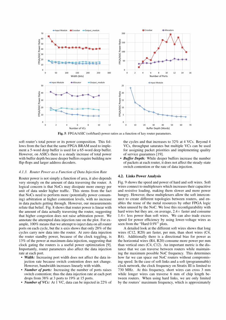
Width: Fig. 5 shows how the power gap between hard andsoft routers varies with NoC parameters. The first plot showsthat increasing the router’s flit width reduces the gap. For ex-ample, 16 bit soft crossbars consume 65× more power thanhard crossbars, while that gap drops to approximately 40× atwidths higher than 64 bits. The same is true for input mod-ules where the power gap drops from 18-12×. This indicatesthat the FPGA fabric is efficient in implementing wide com-ponents and encourages increasing flit width as a means toincrease router bandwidth when implementing soft NoCs.
Number of Ports: Unlike width, increasing the number ofrouter ports proved unfavorable for a soft router implemen-tation. The allocators power gap is 57× at high port countcompared to 35× at low port count. For crossbars, the powergap triples from 50× at six or less ports, to 150× with ahigher number of ports. This suggests that low-radix soft NoCtopologies, such as rings or meshes, are more efficient on tra-ditional FPGAs than high-radix and concentrated topologies.
Number of VCs and Buffer Depth: Increasing the numberof VCs is another means to enhance router bandwidth be-cause VCs reduce head-of-line blocking [19]. This requiresmultiple virtual FIFOs in the input buffers and more complexcontrol and allocation logic. Because we use BRAMs for theinput module buffers on FPGAs, we have enough buffer depthto support multiple large VCs. Conversely, ASIC buffers arebuilt out of registers and multiplexers and are tailored to fitthe required buffer size exactly. As a result, the input modulepower gap consistently becomes smaller as we increase theuse of buffers by increasing either VC count or buffer depth,as shown in Fig. 5.
Allocators are composed of arbiters, which are entirelycomposed of logic gates and registers. Increasing the numberof VCs increases both the number of arbiters and the width ofeach arbiter. The overall impact is a weak trend – the powerratio between soft and hard allocators narrows slightly as thenumber of virtual channels increases.
4.1.2. Router Power Composition
Figures 6 and 7 show the percentage of dynamic power con-sumed by each of the router components and the total routerpower is annotated on the top axes. Clearly most of the poweris consumed by the input modules, as shown by previous work[8, 13], but the effect is weaker in soft NoCs than in hard. Thisalso conforms with the area composition of the routers; mostof the router area is dedicated to buffering in the input mod-ules, while the smallest router component is the crossbar [1].Indeed, the crossbar power is very small compared to otherrouter components as shown in the figures.
Next we look at the power consumption trends when vary-ing the four router parameters. As we increase width, therouter datapath consumes more power while the allocator’spower remains constant. When increasing the number of portsor VCs, the proportion of power consumed by the allocatorsincreases since there are more ports and VCs to arbitrate be-tween. With deeper buffers, there is almost no change in the
Fig. 5: FPGA/ASIC (soft/hard) power ratios as a function of key router parameters.
soft router’s total power or its power composition. This fol-lows from the fact that the same FPGA BRAM used to imple-ment a 5-word deep buffer is used for a 65-word deep buffer.However, on ASICs there is a steady increase of total powerwith buffer depth because deeper buffers require building newflip-flops and larger address decoders.
4.1.3. Router Power as a Function of Data Injection Rate
Router power is not simply a function of area, it also dependsvery strongly on the amount of data traversing the router. Alogical concern is that NoCs may dissipate more energy perunit of data under higher traffic. This stems from the factthat NoCs need to perform more (potentially power consum-ing) arbitration at higher contention levels, with no increasein data packets getting through. However, our measurementsrefute that belief. Fig. 8 shows that router power is linear withthe amount of data actually traversing the router, suggestingthat higher congestion does not raise arbitration power. Weannotate the attempted data injection rate on the plot. For ex-ample, 100% means that we attempt to inject data on all routerports on each cycle, but the x-axis shows that only 28% of thecycles carry new data into the router. At zero data injectionthe router standby power, because of the clock toggling, is13% of the power at maximum data injection, suggesting thatclock gating the routers is a useful power optimization [9].Importantly, router parameters also affect the data injectionrate at each port.
• Width: Increasing port width does not affect the data in-jection rate because switch contention does not change.However, bandwidth increases linearly with width.
• Number of ports: Increasing the number of ports raisesswitch contention; thus the data injection rate at each portdrops from 38% at 3 ports to 19% at 15 ports.
• Number of VCs: At 1 VC, data can be injected in 22% of
the cycles and that increases to 32% at 4 VCs. Beyond 4VCs, throughput saturates but multiple VCs can be usedfor assigning packet priorities and implementing qualityof service guarantees [19].
• Buffer Depth: While deeper buffers increase the numberof packets at each router, it does not affect the steady-stateswitch contention or the rate of data injection.
4.2. Links Power AnalysisFig. 9 shows the speed and power of hard and soft wires. Softwires connect to multiplexers which increases their capacitiveand resistive loading, making them slower and more powerhungry. However, these multiplexers allow the soft intercon-nect to create different topologies between routers, and en-ables the reuse of the metal resources by other FPGA logicwhen unused by the NoC. We lose this reconfigurability withhard wires but they are, on average, 2.4× faster and consume1.4× less power than soft wires. We can also trade excessspeed for power efficiency by using lower-voltage wires asseen from the “Hard 0.9V” plots.
A detailed look at the different soft wires shows that longwires (C12, R20) are faster, per mm, than short wires (C4,R4). Additionally there is a directional bias for power asthe horizontal wires (R4, R20) consume more power per mmthan vertical ones (C4, C12). An important metric is the dis-tance that we can traverse between routers while maintain-ing the maximum possible NoC frequency. This determineshow far we can space out NoC routers without compromis-ing speed. In the case of soft links and a soft (programmable)clock network, the clock frequency on Stratix III is limited to730 MHz. At this frequency, short wires can cross 3 mmwhile longer wires can traverse 6 mm of chip length be-tween routers. When using hard links, we are only limitedby the routers’ maximum frequency, which is approximately
18 35 58 74 93 113
0%
20%
40%
60%
80%
100%
16 64 112 160 208 256
Router Power (mW)
Pow
er C
om
po
siti
on
Width (bits)
15 23 41 54 69 103 123
0%
20%
40%
60%
80%
100%
3 5 7 9 11 13 15
Router Power (mW)
Pow
er C
om
po
siti
on
Number of Ports
17 35 46 56 70
0%
20%
40%
60%
80%
100%
1 3 5 7 9
Router Power (mW)
Pow
er C
om
po
siti
on
Number of VCs
21 24 23 24 23
0%
20%
40%
60%
80%
100%
5 20 35 50 65
Router Power (mW)
Pow
er C
om
po
siti
on
Buffer Depth (Words)
Fig. 6: FPGA (soft) router power composition by component and total router power at 50 MHz. Starting from the bottom (red): Inputmodules, crossbar, allocators and output modules.
0.9 2.4 3.9 5.4 6.8 8.2
0%
20%
40%
60%
80%
100%
16 64 112 160 208 256
Router Power (mW)
Pow
er C
om
po
siti
on
Width (bits)
0.9 1.4 2.1 2.6 3.2 3.9 4.4
0%
20%
40%
60%
80%
100%
3 5 7 9 11 13 15
Router Power (mW)
Pow
er C
om
po
siti
on
Number of Ports
0.8 2.0 3.2 4.3 5.5
0%
20%
40%
60%
80%
100%
1 3 5 7 9
Router Power (mW)
Pow
er C
om
po
siti
on
Number of VCs
0.8 2.1 3.1 4.0 4.6
0%
20%
40%
60%
80%
100%
5 20 35 50 65
Router Power (mW)
Pow
er C
om
po
siti
on
Buffer Depth (Words)
Fig. 7: ASIC (hard) router power composition by component and total router power at 50 MHz. Starting from the bottom (red): Inputmodules, crossbar (very small), allocators and output modules.
0
0.25
0.5
0.75
1
0 5 10 15 20 25 30
Rel
ativ
e R
ou
ter
Pow
er
Actual Flit Injection Rate (% of Cycles)
0%
80% 60%
40%
20%
5%
100%
Fig. 8: Baseline router power at actual data injection rates relative tothe its power at maximum data injection. Attempted data injectionis annotated on the plot.
900 MHz. At this frequency, hard links can traverse 9 mmat 1.1 V or 7 mm at 0.9 V. Although lower-voltage wires areslower, they conserve 40% dynamic power compared to wiresrunning at the nominal FPGA voltage.
5. SYSTEM-LEVEL COMPARISON
This section investigates the power consumed by completeNoCs, especially the mixed and hard NoCs presented in Sec-tion 2. We investigate how the width of NoC links and spacingof NoC routers affect power consumption. Additionally, wereport how much of the FPGA’s power budget would be spentin these hard NoCs under worst-case traffic, if they are usedfor global communication.
We calculate the energy per unit of data moved by NoCsas an important figure of merit. This is used to compare theenergy efficiency of different hard and soft NoCs. We alsocompare the energy per data of NoCs to conventional point-to-point links on the FPGA. Although point-to-point linksmerely connect two modules and are incapable of arbitrationand switching between many nodes, this comparison showshow the presented NoCs compare to best-case conventionalinterconnect on the FPGA. We show that we can design a
hard NoC that uses approximately the same energy as regular(soft) point-to-point links on the FPGA.
5.1. Power-Aware NoC DesignFig. 10 shows the total dynamic power of mixed and hardNoCs as we vary the width. When we increase the width ofour links we also reduce the number of routers in the NoCsto keep the aggregate bandwidth constant at 250 GB/s. Forexample, a 64-node NoC with 32-bit links has the same totalbandwidth as a 32-node NoC with 64-bit links. However, withfewer routers the links become longer so that the whole FPGAarea is still reachable through the NoC, albeit with coarsergranularity. We assume that our NoCs are implemented on anFPGA chip whose core is 21 mm in each dimension as in thelargest Stratix III device [20].
The power-optimal NoC link width varies by NoC typeas Fig. 10 shows. The most power-efficient mixed NoC has32-bit wide links and 64 nodes. However, for hard NoCs theoptimum is at 128-bit width and 16 router nodes. The dif-ference between the two NoC types is a result of the rela-tive router:links power. With fewer but wider nodes, the totalrouter power drops as the control logic power in each routeris amortized over more width and hence more data. However,the link power increases since longer wires are used betweenthe more sparsely distributed router nodes. Because soft linksconsume more power than hard links, they start to dominatetotal NoC power earlier than hard links as shown in Fig. 10.
Fig.11 shows the NoC power dissipated in routers com-pared to links for a 64-node NoC. On average, soft links con-sume 35% of total NoC power, while hard links consume26%. For NoCs with fewer nodes (and hence longer links),the relative percentage of power in the links is higher.
5.2. FPGA Power BudgetWe want to find the percentage of an FPGA’s power budgetthat would be used for global data communication on a hardNoC. We model a typical, almost-full2 FPGA using the Early
0
200
400
600
800
1000
1200
0 5 10 15 20
Freq
ue
ncy
(M
Hz)
Length (mm)
Hard 1.1V
Hard 0.9V
C12
R20
R4
C4
0
10
20
30
40
50
60
0 5 10 15 20
Pow
er (
uW
)
Length (mm)
R20
R4
C12
C4
Hard 1.1V
Hard 0.9V
Fig. 9: Hard and soft interconnect wires frequency, and power at 50 MHz and 15% toggle rate.
1
2
3
4
0 100 200 300 400 500 600
No
C P
ow
er (
W)
Width (bits)
Mixed NoC (1.1V)
Hard NoC (1.1V)
Hard NoC (0.9V)
16 bits 128 nodes
32 bits 64 nodes
64 bits 32 nodes
128 bits 16 nodes
256 bits 8 nodes
512 bits 4 nodes
Fig. 10: Power of mixed and hard NoCs with varying width andnumber of routers at a constant aggregate bandwidth of 250 GB/s.
35%
65% Soft Links
Hard Routers
26%
74% Hard Links
Hard Routers
Fig. 11: Power percentage consumed routers and links in a 64-nodemixed/hard mesh NoC.
Power Estimator [21]. The largest Stratix III FPGA core con-sumes 20.7 W of power in this case, divided into 17.4 W dy-namic power and 3.3 W static power. Note that 57% of thispower is in the interconnect, while 43% is consumed by logic,memory and DSP.
Aggregate (or total) bandwidth is the sum of availabledata bandwidth over all NoC links accounting for worst-case contention. A 64-node mixed NoC can move 250 GB/saround the FPGA chip using 2.6 W, or 15% of the typicallarge FPGA dynamic power budget of 17 W. A hard NoCis more efficient and consumes 1.9 W or 11% at 1.1 V and1.3 W or 7% at 0.9 V. This implies that only 3-6% of theFPGA power budget is needed for each 100 GB/s of NoCcommunication bandwidth.
To put this in context, 250 GB/s is a large aggregate band-width. A single 64-bit DDR3 interface running at the currentmaximum frequency supported by any FPGA of 933 MHz,
2Only core power is measured excluding any I/Os. We assume that ourfull FPGA runs at 200 MHz, has a 12.5% toggle rate, and is logic-limited.90% of the logic is used, and 60% of the BRAMs and DSPs.
produces a maximum data rate of 14.6 GB/s. A PCIe Gen3x8 interface produces 8.5 GB/s of data in each direction. Ifthis data is transferred to various masters and slaves locatedthroughout the entire FPGA, the average distance traveled ishalf the width or height of the chip, or 4 routers. Hence an ag-gregate NoC bandwidth of (14.6×4)+(8.5×2×4)=126 GB/scan distribute the maximum data from these high-speed inter-faces throughout the entire FPGA chip.
5.3. Comparing NoCs and FPGA InterconnectWe suggest the use of NoCs to implement global connec-tions between compute modules on the FPGA; as such, wemust compare to existing communication methods. There aretwo main types of interconnect that can be configured on theFPGA. The first uses only soft wires to implement a directpoint-to-point connection between modules or to broadcastsignals to multiple compute modules. The second type of in-terconnect is composed of wires, multiplexers and arbiters toconstruct buses. This is often used to connect multiple mas-ters to a single slave, e.g. connecting multiple compute mod-ules to external memory. Although the proposed NoCs canimplement both of these communication requirements (point-to-point and arbitration), we compare our NoC power con-sumption with the simplest FPGA point-to-point links. TheFPGA point-to-point links consist of a mixture of differentFPGA wires that are equal in length to a single NoC link;10,000 wires running at 200 MHz can provide a total band-width of 250 GB/s. We assume large packets on the NoC, sothat the overhead of a packet header is negligible. Neverthe-less, this comparison favors the FPGA links, because NoCscan move data anywhere on the chip as well as perform arbi-tration, while the direct links are limited in length to an NoClink and can perform no arbitration or switching.
Table 3 shows the result of this comparison. We start bylooking at a completely soft NoC that can be configured onthe FPGA without architectural changes. Under high traf-fic, this NoC consumes 5.1 W of power or approximately onethird of the FPGA’s power budget. However, because its clockfrequency is only 167 MHz, it has a relatively low aggregatebandwidth of 54 GB/s. This means that moving 1 GB of dataon this soft NoC costs 95 mJ of energy. Conventional point-to-point links only consume 4.7 mJ/GB; soft NoCs seem pro-hibitively more power-hungry in comparison.
Next, we look at mixed and hard NoCs. A mixed NoCis limited to 730 MHz because of the maximum speed ofthe FPGA interconnect; nevertheless, this is enough to pushthis NoC’s aggregate bandwidth to 238 GB/s. Note that wecalculate bandwidth from simulations and so we account fornetwork contention in these bandwidth numbers. With hard
Table 3: System-level power, bandwidth and energy comparison of different FPGA-based NoCs and regular point-to-point links.
FPGA-based NoCs
NoC Type NoC Links Description Total Power Aggregate Bandwidth Energy per Data
Soft 64-NoC Soft 1.1V, 167 MHz, 32 bits, 2 VCs 5.14 W 54.4 GB/s 94.5 mJ/GBMixed 64-NoC Soft 1.1V, 730 MHz, 32 bits, 2 VCs 2.47 W 238 GB/s 10.4 mJ/GBHard 64-NoC Hard 1.1V, 943 MHz3, 32 bits, 2 VCs 2.67 W 307 GB/s 8.68 mJ/GBHard 64-NoC Hard 0.9V, 943 MHz, 32 bits, 2 VCs 1.78 W 307 GB/s 5.78 mJ/GBHard 64-NoC Hard 0.9V, 1035 MHz, 32 bits, 1 VC 1.21 W 236 GB/s 5.13 mJ/GBHard 64-NoC Hard 0.9V, 957 MHz, 64 bits, 1 VC 1.95 W 437 GB/s 4.47 mJ/GB
Conventional Point-to-Point FPGA Interconnect
FPGA Interconnect Resource Description Total Power Aggregate Bandwidth Energy per Data
Equal use of C4,12 and R4,20 1.1V, 200 MHz, 10000 bits 1.18 mW 250 GB/s 4.73 mJ/GB
routers and soft links, this NoC consumes 2.5 W or 10 mJ/GB,which is 2.2× that of point-to-point links.
A hard NoC can run as fast as the routers at 943 MHzraising the aggregate bandwidth to 307 GB/s. The energy perdata for this NoC is 8.7 mJ/GB; 1.8× more than conventionalFPGA links. In Section 2 we discussed that this completelyhard NoC can run at a lower voltage than the FPGA. Whenlooking at the same hard NoC running at 0.9 V instead of1.1 V, the energy per data drops to 5.8 mJ/GB; 22% higherthan conventional FPGA wires.
Next, we look at the overhead of VCs by investigatinga one-VC version of our hard NoC running at 0.9 V. Somehave suggested that VCs consume area and power excessively[5]. Table 3 confirms that supporting multiple VCs does re-duce energy efficiency. Moving to one VC increases block-ing at router ports, reducing aggregate bandwidth by 23% to236 GB/s. However, power drops by 35% resulting in a re-duced energy per data of only 5.1 mJ/GB, a mere 8% higherthan the conventional FPGA wires.
Finally, by increasing the flit width of the NoC from 32to 64 bits, we double its bandwidth while increasing powerby only 61%. This increases energy efficiency to 4.5 mJ/GB,as the router control logic power is amortized over more databits. This energy per data is 6% lower than that of the con-ventional FPGA wires (4.7 mJ/GB).
These findings lead to two important conclusions. First,the most energy-efficient NoC avoids VCs, uses a wide flitwidth, has hard links and a reduced operating voltage. Sec-ond, an embedded hard NoC with hard links on the FPGA canmatch or even exceed the energy efficiency of the simplestFPGA point-to-point links. This means that a hard NoC, in-tegrated within the FPGA fabric, can implement global com-munication more efficiently than any soft interconnect thatincludes arbitration and switching. Hard NoCs are not onlyarea-efficient and fast [1], but energy efficient as well.
6. CONCLUSION
We studied how the power consumption of hard and soft NoCcomponents varies with design parameters and data injectionrates, and used that as the basis for designing energy-efficientNoCs. We presented mixed NoCs that use soft links to forman arbitrary topology and quantified their power consumptionat ~6% of the FPGA’s power budget for each 100 GB/s of databandwidth. Hard NoCs consisting of hard routers and hard
31.1 V routers can exceed 943 MHz as this frequency is achieved at 0.9 V.
links are more power efficient, partially because they can bedesigned with a separate lower-voltage power grid. Our mostpower-efficient hard NoCs use only 4.5 mJ/GB to move dataaround an FPGA chip under high traffic, or ~3% of the FPGApower budget per 100 GB/s. This is less than the energy re-quired to move data on point-to-point soft links that are inca-pable of arbitration or switching, indicating that hard NoCscan result in overall power savings for FPGAs.
REFERENCES[1] M. S. Abdelfattah and V. Betz, “Design Tradeoffs for Hard and Soft
FPGA-based Networks-on-Chip,” FPT, 2012, pp. 95–103.[2] E. S. Chung, et al., “CoRAM: An In-Fabric Memory Architecture for
FPGA-based Computing,” FPGA, 2011, pp. 97–106.[3] B. Sethuraman, et al., “LiPaR: A Light-Weight Parallel Router for
FPGA-based Networks-on-Chip,” GLSVLSI, 2005, pp. 452–457.[4] M. K. Papamichael and J. C. Hoe, “CONNECT: Re-Examining Con-
ventional Wisdom for Designing NoCs in the Context of FPGAs,”FPGA, 2012, pp. 37–46.
[5] Y. Huan and A. DeHon, “FPGA Optimized Packet-Switched NoC usingSplit and Merge Primitives,” FPT, 2012, pp. 47–52.
[6] R. Francis and S. Moore, “Exploring Hard and Soft Networks-on-Chipfor FPGAs,” FPT, 2008, pp. 261–264.
[7] K. Goossens, et al., “Hardwired Networks on Chip in FPGAs to UnifyFunctional and Configuration Interconnects,” NOCS, 2008, pp. 45–54.
[8] G. Guindani, et al., “NoC Power Estimation at the RTL AbstractionLevel,” VLSI, 2008, pp. 475 –478.
[9] R. Mullins, “Minimising Dynamic Power Consumption in On-ChipNetworks,” SoC, 2006, pp. 1–4.
[10] H.-S. Wang, et al., “A power model for routers: modeling Alpha 21364and InfiniBand routers,” Micro, vol. 23, no. 1, pp. 26–35, 2003.
[11] A. Sharifi, et al., “PEPON: Performance-Aware Hierarchical PowerBudgeting for NoC Based Multicores,” PACT, 2012, pp. 65–74.
[12] A. Lambrechts, et al., “Power breakdown analysis for a heterogeneousNoC running a video application,” ASAP, 2005, pp. 179–184.
[13] F. Angiolini, et al., “Contrasting a NoC and a traditional interconnectfabric with layout awareness,” DATE, 2006, pp. 124–129.
[14] Daniel U. Becker, “Efficient Microarchitecture for Network-on-ChipRouter,” Ph.D. dissertation, Stanford University, 2012.
[15] Altera Corp., “Stratix III FPGA: Lowest Power, Highest Performance65-nm FPGA,” Press Release, 2007.
[16] I. Kuon and J. Rose, “Measuring the Gap Between FPGAs and ASICs,”TCAD, vol. 26, no. 2, pp. 203–215, 2007.
[17] J. Rabaey, et al., Digital Integrated Circuits, A Design Perspective,2nd ed. Upper Saddle River, NJ: Pearson Education, Inc., 2003.
[18] W. Dally and B. Towles, “Route Packets, Not Wires: On-Chip Inter-connection Networks,” DAC, 2001, pp. 684–689.
[19] W. J. Dally and B. Towles, Principles and Practices of InterconnectionNetworks. Boston, MA: Morgan Kaufmann Publishers, 2004.
[20] H. Wong, et al., “Comparing FPGA vs. Custom CMOS and the Impacton Processor Microarchitecture,” FPGA, 2011, pp. 5–14.
[21] Altera Corp., “Stratix PowerPlay Early Power Estimator.” [Online].


![EFFICIENT ANALOG COMMUNICATION OVER - [email protected]](https://static.documents.pub/doc/80x56/6203a2d8da24ad121e4bb41e/efficient-analog-communication-over-emailprotected.jpg)


