The International Journal of Orthodontia and Oral Surgery (All rights strictly reserved) VOL. VII ST. LOUIS. APRIL, 1921 ORIGINAL ARTICLES No. 4 THE PRINCIPLES OF THE JACKSON REMOVABLE APPLIANCE* By VICTOR HUGO JACKSON, M.A., M.D., D.D.s., NEW YORK CITY I N PRESENTING this paper, it is the purpose of the author to describe the more improved methods of practice in his treatment of "Orthodontia and Or thopedia of the face", considering as far as time will permit, the gen- eral principles and advantages of the removable regulating appliances de- vised by him. The first object in developing a new method of anchorage to the teeth was to perfect one which would permit the appliance to be movable and, at the same time, be securely retained. A movable appliance is one that can be readily removed by the patient and by the operator for cleansing the teeth .and the apparatus. Weare all familiar with fixed regulating appliances. They are anchored to the teeth in such a manner that they cannot readily be removed by the patient for cleansing or by the operator for adjustment. Recently, the whole profession and many patients have begun to realize the great necessity of the careful cleansing of the teeth being carried out systematically by the treatment known as "Prophylaxis" and are becoming aware that, for that reason, regulating appliances and bridges of artificial teeth should be movable. Realizing this necessity, the writer has spent most of his professional life in devising and developing such appliances as would help to prevent decay and save the teeth. A few operators have been opposed to movable appliances. The opposition was due principally to the careless habit of an occasional patient in leaving his regulating appliances out at times, which naturally would interfere with the progress of the regulating. However, by the use of a record card that the 'Read before the meeting of the American Society of Orthodontists, Chicago, AprilS, 1920. 175
Transcript
The International Journal of
Orthodontia and Oral Surgery(All rights strictly reserved)
VOL. VII ST. LOUIS. APRIL, 1921
ORIGINAL ARTICLES
No. 4
THE PRINCIPLES OF THE JACKSON REMOVABLEAPPLIANCE*
By VICTOR HUGO JACKSON, M.A., M.D., D.D.s., NEW YORK CITY
IN PRESENTING this paper, it is the purpose of the author to describethe more improved methods of practice in his treatment of "Orthodontia
and Orthopedia of the face", considering as far as time will permit, the general principles and advantages of the removable regulating appliances devised by him.
The first object in developing a new method of anchorage to the teethwas to perfect one which would permit the appliance to be movable and, atthe same time, be securely retained.
A movable appliance is one that can be readily removed by the patientand by the operator for cleansing the teeth .and the apparatus.
Weare all familiar with fixed regulating appliances. They are anchoredto the teeth in such a manner that they cannot readily be removed by thepatient for cleansing or by the operator for adjustment.
Recently, the whole profession and many patients have begun to realizethe great necessity of the careful cleansing of the teeth being carried outsystematically by the treatment known as "Prophylaxis" and are becomingaware that, for that reason, regulating appliances and bridges of artificialteeth should be movable.
Realizing this necessity, the writer has spent most of his professional lifein devising and developing such appliances as would help to prevent decayand save the teeth.
A few operators have been opposed to movable appliances. The oppositionwas due principally to the careless habit of an occasional patient in leavinghis regulating appliances out at times, which naturally would interfere withthe progress of the regulating. However, by the use of a record card that the
'Read before the meeting of the American Society of Orthodontists, Chicago, AprilS, 1920.
175
176 T he In ternational J ournal of Orthodontia and Oral S urgery
oper ator has at comma nd, this practi ce would be r eadil y det ect ed and thecond it ion correc ted.
When the oper at or has di scovered that a movable apparatus is no t keptin place by th e pati ent a t a ll times, in cluding t ime of mastication , as direct ed,he should immedi at ely li gate th e appliance t o th e anchorage t eeth with wire,makin g it a fixed appliance, which gene rally can be done in a few minut es,and the n direct the patien t to return in four days for further ad just men tof the appliance and for cleans ing . At the same ti me, he should noti fy theparents that th e ligating is necessary, as th e conditions re qu ire that the forceof the appliance should be conti nuous. In wearing the appliance ligated ,t he patient soon learns that it is not so pleasant t o us e a fixed appliance andmake extra visits, as to wear a movable one, keep the t eeth and appliancein a cleansed condition and make fewer visits. When necessary and wellmanaged, this plan works well.
When rubber " equalizing bands" are us ed with a fixed appliance, th echild is quite as apt to deceiv e the operator by leaving off the equalizin gbands, which might prove as harmful as the leav in g out of a movable ap pli ance.
Th e movable regul ating appliances to be described are made of spring-wire.Th ey are so anchored t o t he teeth that th ey can be easi ly r emoved by th epatient for th e clea nsing of the teeth and appl iance.
For this purpose, the patient is direct ed to remove t he appliance aft ereach meal and before r etiring. It can be quickl y removed by the op eratorfor making any necessary cha nges in it s ad justment . Th e movable appliance is made on a model of the t eeth in th e labor atory.
When the model is acc urate, th e applia nce should fit the natural t eethof the arch so 'Yell that ther e would not be any dressing or change r equiredin its adjustment.
APP LIANCES TO DESIGN
Before designing a re gulating apparatus, acc ura te models of the maxillary and mandibular arc hes of th e teeth are made and thoroughly examinedto d etermine how parts of an appliance can best be arranged to correct theirregularity.
All regulating applian ces are designed from the study and measurementof the models and obtainable data regardin g the regulating case. P encildesigns of the apparatus are mad e in a "duplicati ng" or a "triplicating"book ; one copy of th e design r emain s in the book permanently; another, withthe models, aid s the laboratory assistant in understanding th e form of appl iance to be made; and the third copy is utilized in cases of consultat ion, beingforwarded to th e consult ant to assist in describing t he plan of procedure andtreatment.
M ETALS FOR APPLIAN CES
Precious metals for making appliances have always been r ecommended byth e author, but it r equires mu ch more time in making and r epairing them,than when suitabl e base metals are used. H e soon learned that some basemetals have more spring properties and are found to be more efficient, as th ey
The Jackson Removable Appliance 177
are more resi.lient and persistent than others. The use of silver nickel, or Germansiloer, springs has generally been found satisfactory. Its appearance is desirable as it is near the color of platinum which is much less conspicuous thangold. This would prompt its continued use. Polished gold can be seen ata considerable distance from the patient, which, with some would be objectionable.
Another important reason for recommending base metals is that springs canbe more quickly united with chemically pure tin as a solder than with gold, andcan be unsoldered for changing the relationship of the pieces in a few minuteswithout drawing their temper or otherwise injuring them. This does not follow when gold solders are used.
PHOSPHOBRONZE
Phosphobronze of good quality is a satisfactory spring metal. It is similar to gold in color but is useful for making springs and spurs for orthodonticappliances. In use it holds its color well and is more springy than the metalsdescribed. When well drawn, it is tough and suited for much longer servicethan any of the metals mentioned. This is owing to its resilience and persistence. In time, all metals lose their springiness and come to what isknown as a "stand". The metals above mentioned, usually come to a standmuch sooner than the phosphobronze. It is claimed that now there is nolead in its composition. Chemically pure tin, as a solder, has more affinityfor phosphobronze than for most other metals, thereby making a strongerunion. In use there is no special chemical action apparent or waste around
the springs.GOLD PARTIAL CLASP METAL
After much experimentation the writer succeeded in forming a partialclasp metal made of 18 karat gold rolled plate, ~ on German silver, 36 U. S.standard wire gauge. In making an appliance, the gold side rests againstthe tooth, while the solder, chemically pure tin, is applied on the German silverside, because it has more affinity for the German silver than for the gold.The 18 k. gold as purchased in the market was at one time recommended bythe writer for partial clasps but it was found that, after being in use fora time, it would peel from the solder.
LIGHT COLORED BRONZE
Partial clasps made of light colored bronze spring plate, No. 36 gauge, havebeen used in certain cases for several years with thorough satisfaction. Whenused for partial clasps and other parts of an appliance, a:, resting on thegum, etc., the metal keeps bright like gold and does not encourage fermentation,or stain the teeth. In practice, however, the writer is continuing to usc thegold partial clasp metal.
APPLIANCES TO MAKE
The author will describe as in previous writings, his general plan of makingregulating appliances, first speaki.ng of the principal parts of an applianceand their purposes and also his method of uniting them with solder.
178 Th e International J ournoi of Orthodontia and Oral S1trg ery
Th e general parts of an appliance are partial clasps, spring clasps or wireclasps, base wire, spurs and springs. These are usually united with chemicallypure tin as a solder .
In making a regulating appliance, an accurate model is necessary. An ymolar or premolar t eeth that are not fully er upted but are to assist in thean chorage should first have a groove cut in th e plast er of th e model beside thetooth toward th e neck fo r the adjustment of a partial clasp to project underth e gum to strengthen th e anchorage. This is usually done with a rather straight
Fi g. I.
D EFi g. 2. F ig. 3.
hoe excavator. Th e operator mus t be sure to preserve the natural shape ofthe tooth and not remove or injure the plaster representing the gum on thelingual side of th e groove as, in soldering, the solder is liable to run into thisinjured part, which would cause th e appliance when inserted to rest on th egum, while the thin partial clasp would pass between the tooth and gum withoutcausing irritation.
PARTIAL CLASP FOR ANCHORAGE-FIG. I-A
A partial clasp is made of plate metal No. 36 U. S. standar d wire gauge,being of sufficient size to fit the lingual surface of a tooth used for an chorage.It is contoured with a coniourinq pli er having the end of one beak cup shaped
The Jackson Removable Appliance 179
and the other formed to fit it. (Fig. 2.) The partial clasp is always overcontoured to cause it to rest on the tooth at the neck and near the grinding surface.(Fig. I-A, B, C.) A partial clasp is arranged to fit the lingual side of each anchorage tooth, as to two canines or premolars and two molars in each arch. Whenconnected by a base-wire in this manner, the anchorage is quite complete, but withthe improved anchorage, it is generally found advisable to have also partial claspsarranged on all of the teeth in the lateral maxillary divisions of the arch, thatis-the molars, premolars and canines.
CLASPS FOR ANCHORAGE
There have been various forms of clasps devised by the author for anchoring regulating appliances, many of which have previously been described. Following are some of the ordinary examples:
Fig. 4.
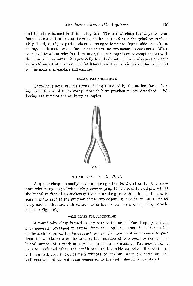
SPRING CLASP-FIG. 3-D, E.
A spring clasp is usually made of spring wire No. 20, 21 or 19 U. S. standard wire gauge shaped with a clasp-bender (F'ig. 4) or a round-nosed pliers to fitthe buccal surface of an anchorage tooth near the gum with both ends formed topass over the arch at the junction of the two adjoining teeth to rest on a partialclasp and be attached with solder. It is then known as a spring clasp attach
ment. (Fig. 3-E.)
WIRE CLASP FOR ANCHORAGE
A round wire clasp is used in any part of the arch. For clasping a molarit is generally arranged to extend from the appliance around the last molarof the arch to rest on the buccal surface near the gum, or it is arranged to passfrom the appliance over the arch at the junction of two teeth to rest on thebuccal surface of a tooth as a molar, premolar, or canine. The wire clasp isusually preferred when the conditions are favorable as, when the teeth arewell erupted, etc., it can be used without collars but, when the teeth are notwell erupted, collars with lugs cemented to the teeth should be employed.
180 The International J ournal of Orthodontia and Oral Surgery
F LAT CL ASP FOR ANCHORAGE
A flat clasp made from plate metal has its advantages. It can be shapedto pa ss between the teeth when desired, at any favorable location for anchora geand, at the same t ime, ext end from the apparatus to rest on the buccal sideof a canine premolar or molar, as described .
LO CKING DEVICE
A locking device of an appliance will be mentioned here and more fullyreferred to lat er. It ha s a collar with a bu ecal lu g re sting near the gum,cemented to a canine or a premolar and to a molar on each side of the arch.A wire clas p is formed to exte nd from the appliance over the arch in f ront (orback) of the canine to engage with the buccal lu g, on each of the collarson the canines and the molars, with the ends of each of the clasps terminat ingin a h ook. Thi s form of anchorage is suited for supporting an apparatus forany class of ir r egular ity of the teeth .
II cII
Fig, 5.B
BASE WIRE
A Base WIre is t he foundation of a regulating appliance. It is a largespring- wir e of good temper, usually made of German silver , silver nickel, orphosphobronze. It can be made of any suitable spring metal. The base wir emay be a rigid or a spring base wire . Th er e are four general forms of basewire-lingual, palatal, palatal with loop, and labio-buccal , The body and armsof a base wire should be sufficiently strong and r igid, so that they will not besprung from their normal position, when necessary force is exerted by strongsprings which are attached and extended from th em for any purpose in moving the teeth.
The different sizes of base wire generally r ecommended are:
For children between the ages of 3 to 6 years No. 13 gauge.For chi ldren between the ages of 6 to 8 years No. 12 gauge.For persons between the ages of 8 to 15 years No. 11 gauge .F or persons between the ages of 15 to 21 years No. 10 gauge.For more mature adults, a more ri gid ba se wire No.9 gauge.
Th e Jackson R emovable Appliance 181
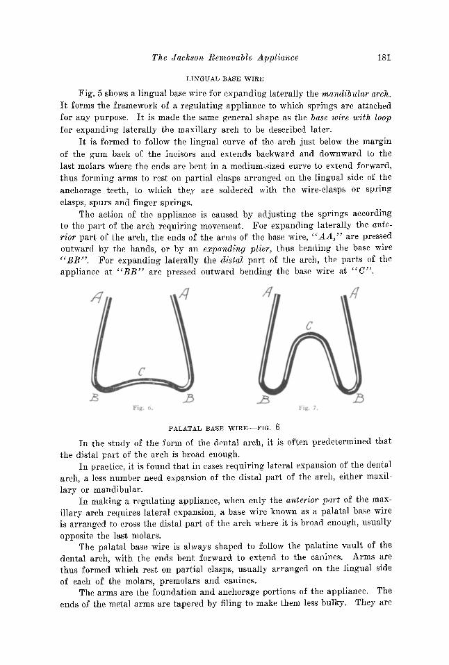
LIN GUAL BASE WIRE
Fig. 5 shows a lingual base wire for expanding laterally th e mandibular arch.It forms th e framework of a regulating appliance to which springs are attachedfor any purpose. It is made the same general shape as the base wire with loopfor expanding laterally the maxillary arch to be descr ibed later.
It is for med to foll ow t he lingu al curve of the arch just below the ma rginof th e gum back of the incisors and extends backward an d downward t o th elast molars where the ends are bent in a medium-sized curve to extend forward,thus forming arms to rest on par tial clasps arranged on the lingual side of theanchorage teeth, to whi ch they are soldered with the wir e-clasps or springclasps, spurs and finger springs.
The action of the appliance is caused by adjusting the springs accord ingto th e part of the ar ch r equir ing movement. For expanding lat erally the anterior part of the arch, the ends of the arms of the base wire, "AA," are pressedoutward by the hands, or by an expanding plier, thus bending the bas e wir e"BB". For expanding laterally the distal part of the ar ch, the parts of theap plia nce at "BB " are pressed outward bend ing t he base wir e at "C".
/I
c
II
c
.BI I'. i .
PALATAL BASE WIRE-FIG. 6
I n the study of the form of th e dental arc h, it is often predetermined th atthe distal part of the arch is broad enough .
I n practice, it is found that in cases requiri.ng lateral expansion of th e dentalarch, a less number need expansion of th e distal part of the arch, either maxi llary or mandibular.
In making a regu lating applian ce, when only the ant erior part of the maxillary arch requires lateral expansion, a base wire known as a palatal base wireis arranged to cross the distal part of the arch where it is broad enough, usuallyopposite the last molars .
The palatal base wire is always shaped to follow the palatine vault of thedental arch, with the ends bent forward to extend to the canines. Arms arethus formed which rest on partial clasps, usually arranged on the lingual sideof each of the molars, premolars and canines.
The arms are the foundation and anchorage port ions of the ap pliance. Theends of the met al arms are tapered by filing to mak e them less bulky. They are
182 Th e International J ourn al of Orthodontia and. Oral Surgery
soldered to the parti al clasp s with the ends of the sp r ing-clasps and fingerspr ings; ar r anged in this manner the ends of the arms are bent outward fromtime t o time to expand the arch in the r egion of the canines and premolars,force bein g cau sed by pressing outward on the ends of the arms "AA" whichbends the base wire at " BB " .
Th e apparatus with the palatal base wire followin g th e palatine vault ofthe arch, as describ ed, is not intended to expand the dist al part of the maxillaryarch as the pala tine curve of th e base wire"C" should never be st r aightened orcha nged for that purpose. It would have more tend ency to tip th e teeth in theirsockets than when a palatal base wire with loop is employed.
PALATAL BASE WIRE WITH LOOP-FIG. 7
When the maxillary arch needs general lateral expansion, a palatal basewire with a U-shaped loop is employed. The ap ex of the loop should alwaysrest deep in the palatine vault, with the sides of the loop extending backward,following the deeper lines of the vault and forming a rather broad outwardcurve toward the molars on each side; the curve should rest distally a littlebeyond the line of th e last molars, with th e ends extending forward formin gar ms and resting on th e lin gu al partial clasps on the molars, premolars, andcanines.
This base wire is similar in for m to a lingual base wire, and its acti on isabout the same.
For expanding the anter ior pa r t of the arc h the ends of the arms c«A A " arepressed outward, bendin g the base wire in the dist al part of the arch at " BB".
When the dist al part of the arch needs exp an sion, outward pressure isexer ted on the sides of th e di st al part of the appliance at " BB" whi ch bendst he loop of th e base wire at "C" in creasin g th e width of the loop. Th esechanges should always be governed by the added measurement as indicatedon a record card.
An appliance with this form of base wire is ad apted for the lateral exp ansion (or contraction ) of either the anterior or the poste r ior part of the arch asneeded, and the expansion can be carried to any desir ed limit, either with themaxillary or the mandibular arch. This, the writer thinks has not been accomplished as accurately with any other single device.
LABI O-BUCCAL BASE WIRE
A labio-buccal base wire has been used many yea rs in expa ndi ng the archand moving individual teeth . It is a curve d bar locat ed on the labial and buccalsides of the dental arch sustained by entering tubes, eyelets or hooks on collarscemented to the teeth , or by spr ing clasp attachments. The labia-bu ccal basewire is used for moving the t eeth as by ligatures, extending from the bar aroundthe teeth, by attached spr ings, ' etc. For retaining the teeth it may be sustainedby spring clasp attachment s or by spurs projecting from the base wire to entertubes, eyelets, or hooks on collars or by spurs projecting f rom collar s cemented tothe t eeth. (F ig . 8.) I ts size varies according t o t he fo rce desired . Manyyea rs the author used labia-buccal base wir es of var ious forms, as a plain base-
The Jackson Removable Appliance 183
wire, or a base wire with corrugations, U-shaped loops, etc. The base wire withloops is often the most serviceable.
The palatal and lingual base wires previously referred to are adaptedto the particular purpose needed. It will be noted that they are generally ofrather large diameter and purposely made stiff, to serve as a foundation forthe regulating appliance and to prevent the teeth from moving back and forthin their sockets, as during mastication, while being regulated, and, while beingretained. In this manner tenderness is avoided. Often when the teeth are supported only by a small spring, they are easily disturbed in their sockets and become more or less tender, delaying new bone deposits, and consequently therewould be an inclination on the part of the patient to avoid necessary normal mastication. Accordingly, with the former plan, there is less tendency to excessiveabsorption of the alveolar process and less irritation and general tenderness of
Fig. 8.
A
Fig. 9.
the teeth than when small springs are used. As noted, the action of the largespring base wire is controllable and the extent of each movement is limited asdesired.
SPRINGS
Springs for moving the teeth as referred to, are made of silver-nickel,phosphobronze, or spring-gold. Any suitable spring metal desired can be used.The sizes usually employed are Nos. 18, 19, 20, or 21 U. S. standard wire gauge.
Springs are usually named according to their shape, position or purpose, asfinger springs, loop-shaped springs, semicircular springs, etc., several forms ofwhich are shown in this paper.
SPURS
The appliance is arranged so that it will be supported by the teeth to prevent it from resting unduly on the gum tissue. For this, a wire spur (Fig.16) is attached to the body of the apparatus and shaped to extend and restusually on the crown of a molar and a premolar on each side of the arch.
184 The Lniernaiionas Journal of Orthodontia and Oral Surgery
SHELF
Another method of supporting the appliance that is superior 111 somerespects for this purpose is to attach a shelf on the lingual side of eachcollar used for the anchorage-locking-device, the spur or shelf being at-
Fig. 10
Fig, 11.
tached to the gingival edge of the collar near the gum line. (Figs. 9 and Fig.16B.)
A similar shelf is also used in case of close occlusion of the teeth and formoving teeth bodily. The shelf is usually made of plate metal about 28 gauge,arranged to project from the collar about two millimeters, the parts being properly fitted and soldered in the usual manner. The collar is then cemented tothe tooth and a model made representing the collar and shelf in place.
The appliance is designed and the parts arranged on the model to rest on the
The Jackson Removable Appliance 185
shelves with the wire clasps extending to the buccal side to complete the anchorage.
When a regulating appliance has been designed, the different parts are always shaped to the model and then assembled, to be united by solder. (Fig. 10.)
SOLDERING-FIG. 11
In soldering, the base wire, spurs and springs are usually held by moldinein position for the soldering and, when necessary, further sustained by press
ing steel pins by the side of them into the model.
SOLDER
Chemically pure tin is usually employed as a solder in uniting the partsof the appliance, the tin being fused by a large soldering iron. Before soldering,the parts are fillxed with chloride of zinc or with a no-korode flux.
Knowing the detrimental systemic effects of lead, the writer early becameconvinced that in making these appliances it was not wise to use a solder that
Fig. 12.
contained lead, but he wishes to say that he has never known of any case whereharm resulted from the use of such a solder.
When lead is excluded from the metals used in an appliance, it has alsobeen found by long experience that there is less chemical action caused 111
acid mouths and consequently less oxidation or tarnish of the appliance.The practice of gold plating or guilding a regulating appliance made in
this manner is generally objectionable, as gold, chemically deposited on thewhole of an appliance is porous and when bathed in saliva, sometimes developsa chemical action, which causes the metal to tarnish more than when no platingis employed. However, when gold plating is to be used, it is usually advisableto first apply a coating of copper and then a good coating of gold.
DIVISIONS OF THE DENTAL ARCH-FIG. 12
In the study of the dental arch for the purpose of orthodontia, as forexpanding the arch or bringing about any necessary correction in the positionof the teeth or for any other purpose, the writer has found it an advantage todivide the arch into three divisions, sections, or segments; as, The Right Max-
186 The Lnternational Journal of Orthodontia and Oral Surgery
illary Division, The Left Maxillary Dioision, and the I nterrnaxillary (or Incisive) Division.
These divisions of the maxillary arch are the natural divisions as separatedand distinguished by the lines of the premaxillary and intermaxillary sutures.The intermaxillary division contains the four incisor teeth. Each lateral divisionof the arch includes the canine, premolars and molars. The divisions can besymbolized as follows: R-M-D
L-M-DI-M-D
To complete this system for study, record, and convenience the mandibulararch is separated into similar divisions.
Accordingly in the examination of orthodontic cases, one should determinein what division of the arch the irregularity is located.
The regulating appliances described are also divided into three divisions,constructed to deal with the irregularity presented in each division of the arch.
Fig. 13.
EXPANSION OF THE ARCH
When the teeth are irregular, they are usually much crowded in the arch.This is most generally evidenced by there being insufficient space between thecanines for the proper arrangement of the four incisors.
Many operators are making a mistake in expanding the dental arch to provide room for the incisors by moving outward the premolars and molars withoutmoving outward at the same time the canines, which are included in the lateralmaxillary divisions of the arch.
Fig. 13 is prepared to illustrate the lines of movement of the teeth in properly expanding the arch laterally. It shows that the movement of the molars andpremolars in a buccal direction, as illustrated by the lines, "0, D, E and F,"does not increase the width of the arch anterior to them as required.
Therefore, in expanding the dental arch laterally, the appliance shouldalways be arranged to include the canines, if present. With these conditionspresented in such a large majority of cases, it has been necessary to devise astandard appliance, strong and complete in itself, that is definite, thoroughlyefficient and which can be handled. It must have a strong foundation to which
The Ja ck son R emovable Appli an ce 187
sprmgs are attached , for susta ining the an chora ge and for individual tooth
movement.ANALOGY
To impress upon th e mind the analogy between r emovabl e r egulating ap pliances and th e human body , th e author will r efer to the man y necessary mechanical features embod ied, th eir capabili t y and th eir impressive similar ity in formand act ion, an underst an d ing of which he is sure will prove instructive andbeneficial.
The base wire is the founda t ion or body of a re gulating appliance. Aspreviously stated, it is mad e of large spring wire. Th e portion of the basewire connecting the lateral divisions of an appliance is always rather largeand strong; the ends are bent to project forward , (or backward), like arms ;th ey are shaped to rest on the partial clasps, usually on th e lingual side of th eanchorage teeth,
Th e base wire or body may be compared to th e human body with the armsex tend ing forw ard fr om th e shoulders, as the arms of th e base wire extend forward from its body or should ers. Th er e are finger s on th e ends of our armsand, lik ewise, there are metal finge rs arranged to project fro m th e ends of th emetal arms of an applian ce in t he form of spr ings .
Th erefore, in mak ing a ' regulating appliance, it is essent ial that it havea st rong body, strong arms, and st rong fingers, as each is to do a definite work.Th ey should be large and st rong enough to move t he teeth a definite di stance ina given tim e and not move the t eeth further th an int ended.
If a man be not st rong enough to accomplish promptly the work laid outfor him , a st ronge r man is employed.
Followin g the same idea, one would make a regulating appliance st rong,alway s having it built st rong enough to cause th e arms and fingers to act definitely in making the desired movement of the teet h and process.
Again, the human body p er for ms all movemen ts by mus cular ac t ion; ineffect , this is similar to th e actio n of the sprin g parts of the regulating ap pl iance .
The fingers of the hu man body grasp obj ects and move them definite distances with ease, foll owin g the command of th e will.
The plan of this system of r egulating is to hav e an appliance built sufficieut ly strong and so th oroughly anchored, as to move th e teeth in th e desired direction, in a lim ited ti me.
Th e analogy menti oned will be apparent in the study of th e d iffer enta ppliances presented , thus making some of th e details in th eir description morereadily understood.
In d esigning an appara tus for movin g th e teet h, one would gene ra lly be ledto adopt correct fo rm s of m etal ar ms and fillgers, etc., by first shaping hisfinger as he would to move a similar obj ect.
ORTHO DON TIA AN EXACT SCIEN CE
Or th odonti a has been rccogn ized as a science, but it is desirable th at th edifferent phases of or thodontia be so thor oughl y understood as t o dedu ce it
188 T he In ternationai J our nal of Orthodontia and Oral Surgery
to an exact science and that the mechanics be so simplified that an y operatorof steady judgment can perform at least ordi nary operat ions without overtaxin g his mechanical skill.
RECORD CARD
To secure accuracy in applying forc e for the regulation of the teeth, several years since, the author devised a meth od of making a carefu l pencil-tracingon a record card of each r egulat ing appliance in use before. ap plying force, andindicating on the card a record of t he amount of each subsequent change in the
Fig. 14.
applian ce for moving the t eeth. Thi s would be a permanent record of thechan ges of force applied and the dat e of th e change," Th e plan is further r eferred t o in th e following .
Fig. 14 illu strates a case with narrow arches and distal occlusion witha maxillary and a mandibular applia nce mad e as previously descr ibed and utilizedfor expanding and equalizing the arc hes for a child four years of age. Th e maxillary appliance has a palatine base wire; th e mandibular appliance a lingualbase wire; force is caused by bending outward the arms and adjusting thesprings of each appliance by rule. With th ese appliances shown, force forthe later al expans ion of the maxill ary arch would be caused by grasping with
"Jackson, Orthod ont ia 1904, page 113.
Th e J ackson R emovable Appl ian ce 189
the hands th e front end of th e arms of th e appliance an d pulling outward,thus bending th e base-wire slightly, which, when inserted in the mouth, wouldcau se force to exp and the front part of the arch. In applying force for thelat eral expansion of the mandibul ar arch, the fr ont ends of th e arms should bepulled outward. Th is would bend the ba se-wir e at th e curv es opposite themolars which would affect th e expa nsion of the front part of the arch. Forexpa nding the distal part of the arch, one would pull outward on the sidesof th e di stal end of t he applian ce, which would bend th e loop of th e basewire as necessary.
E ach of th e mentioned cha nges of form would be governed by the successive measurement in dicated on the record card.
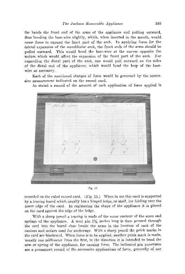
As stated a record of th e amount of each application of forc e ap pli ed is
Fig. 15.
r ecorded on th e ruled record card. (Fig. 15.) 'When in use this card is supportedby a tra cing boarti which usually has a hin ged ledge, or shelf , for folding over th elower edge of the card . In registering the shape of th e applian ce it is placedon th e card against th e edge of th e ledge.
'With a sharp pencil a tracing is mad e of th e outer contour of th e arms andsprings of the appliance. A steel pin 1% in ches long is th en pressed throughthe card into the board close beside the arm s in the location of each of thecanines and molars used for an chorage. With a shar p pencil the prick marks inthe card are blackened . When force is to be applied, another pri ck mark is made,usu ally one millimeter from th e first, in the dir ection it is intended to bend th earm or spr ing of the applianee, for causing force. Th e indicated pin puncturesare a permanent r ecord of th e successive applicat ions of force, generally of one
190 The International Journal of Orthodontia and Oral Surgery
millimeter. The arms of the appliance are bent outward to rest against thepins after the added measurements. Each of these indicated changes of force isknown as a "step". The first step, generally being one-half millimeter, later onemillimeter, should be made at intervals of once a week. When the regulating isadvanced considerably and it is desirable, visits may be made once in two weeksor even at longer intervals.
In some cases, it is wise not to advance in the movement too rapidly, although a change of more than one millimeter is often made without discomfortto the patient. In the expansion of the arch laterally, it generally requires achange of only a few millimeters. From each step recorded on the record card,a line is extended upward for recording the date of the change.
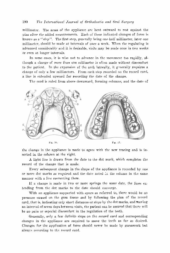
The card is ruled from above downward, forming columns, and the date of
Fig. 16.
the change in the appliance is made to agree with the new tracing and is inserted in the column at the right.
A light line is drawn from the date to the dot mark, which completes therecord of the change that is made.
Every subsequent change in the shape of the appliance is recorded by oneor more dot marks as required and the date noted in the column in the samemanner with a line connecting them.
If a change is made in two or more springs the same date, the lines extending from the dot marks to the date should converge.
'With an appliance supported with spurs as referred to, there would be nopressure caused on the gum tissue and by following the plan of the recordcard, that is, indicating only short distances or steps by the dot marks, and reavingan interval of seven days between visits, the patient can be assured that there willbe no pain or especial discomfort in the regulation of the teeth.
Generally, only a few definite steps on the record card and correspondingchanges in the appliance are required to move the teeth as far as desired.Changes for the application of force should never be made by guesswork butalways according to the record card.
Th e Ja ckson R emovabl e Appliance
IMPROVED ANC HO RAGE WITH I,OCRING DEVICE
191
'l'h e writer will now refer more particularly to the impr oued m eth od ofan choring regulating appliances for the equalizing of the maxillary and mandibular dental arch es, and which method ma y be utilized for causing all necessary movements of th e teeth .
lIIAKING APPLIAN CES
'1'0 mak e th ese appliances (F ig. 16 ) a broad collar with a bu ccal luglocated t o rest near th e gum in the cente r of the tooth is cemented to each ofth e maxillary and mandibular canines, A.A. , and a broad colla r with a buccallug located nea r th e gum is cemen ted to each of th e maxilla ry and mandibulardi stal molars of the arch " EE ".
After the collars are cemented in place, accu rate plaster impressions of theteeth and models are made; the models represent the collars w ith lugs or tubesin place.
In making an ap pliance for th e maxillary arch, partial clasps are ar ra ngedon the lin gual side of th e an chorage molars and canines, the part ial clas ps rest in g on the colla rs r epresented in plaster and, when desir ed , partial clasps arealso arra nged on the intervening teeth.
'When the di st al pa rt of the arch is broad enough, a pal atal base-wire " X " isplanned to cross th e arch oppo site the last molars with th e arms extendi ng forward and shaped to rest on the par t ial clasps ar ranged on the lingual side ofthe anc horage te eth.
The appliance is r etained to the teeth by wire clasp s which are solderedwith th e partial clasps, spurs and ends of the semicir cula r sp r ing to the armsof the appliance with chemically pure t in by usin g the solder ing iron. Twowire clasps " PJ.;' '' are shaped to extend fro m the dist al pa rt of the an chor ageportions of th e appliance, one on either side, to clasp the second molars chosenfor an chorage. Th e f ree end of the clasp is mad e to pass above the lug " E "on th e colla r and bent backward u pon itself, forming a ra th er long hook.
T he wire clasps "CC" attached to the anteri or part of the an chorageportions of the ap plian ce, one or either side, are shaped to extend over th e archat th e junct ion of th e lateral in cisor and canine. They fit well in the gro ove andre ach near the gum line 011 the bu ccal surface of the canine, where each is bentbackward in a curve to pass above and engage with th e lu gs on the colla rs located in th e center of th e teeth . Th e end of the clasp is curve d forward on itself ,forming a hook.
Th e wire clasp pa ssing above th e lu g on th e collar for anchorage compl etes the lock ing device of th e ap pliance. In this manner , th e applian ce isheld firm ly in posit ion for causing any movement of the tect h.
Th e appliance is easily r emoved by unhooking or unlocking the claspsfrom the lugs with th e finger, which liberates the appliance. This can be doneeither by the patient or the operator.
'I'he hook-shaped end of the clasp mak es it the best form of attachment tograsp with th e finger nail for unlocking th e applia nce.
1\. hook of th is shape is th oroughly suited for th e adj nstment of r ubber
192 The Lniernationas Journal of Orthodontia and Oral Surgery
equalizing bands as for the correction of protrusion of the maxillary arch or fora prognathous mandibular arch.
By the use of an appliance with a palatine or a lingual base wire and acorrect tracing to direct the changes, the expansion of the arch is made easyand progressive, step by step, in the manner described in connection with therecord card.
An appliance for the expansion, or the equalizing of the mandibular archis made with a lingual base wire No. 10, 11 or 12 gauge. (Fig. 17.) It isanchored to the teeth with wire clasps. The locking device is arranged thesame as in the maxillary arch for retaining the appliance.
A lingual base wire is shaped to follow the lingual curve of the arch. Thefront part, back of the incisors, rests just below the gum line and extends backward and downward to the posterior molars where the ends are curved forward,extending to the canines, forming arms to rest 'on partial clasps arranged onthe lingual side of the anchorage teeth.
The ends of these arms are tapered by filing, so that the front anchorageportions will not be bulky, but they are kept sufficiently large to retain their
strength.The arms are soldered with the other parts-partial clasps, wire clasps,
finger springs and spurs as described.Curved finger springs, as shown, are often utilized in reshaping the line
of the incisors between the canines.The appliance is removed by disengaging the wire clasps from the lugs with
the finger.Fig. 18 illustrates a front view of the maxillary and mandibular dental
arches with the teeth in occlusion after correction on each of which the appliance is arranged in position.
The plan of the locking device for anchorage and the semicircular springs ofthe appliance for moving the incisors are especially shown.
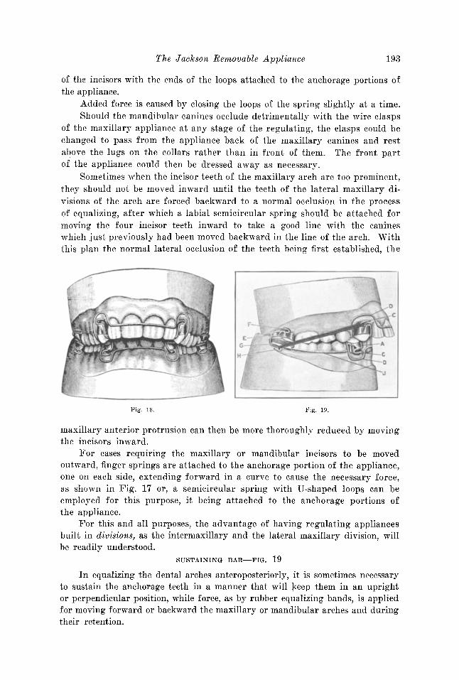
EQUALIZING THE DENTAL ARCHES, ANTEROPOSTERIORLY
Fig. 19 shows the original occlusion of the teeth in the case just describedand illustrated by Figs. 16, 17· and 18. It shows the receding mandibular andmaxillary protruding arches with appliances in place for their correction, byequalizing the dental arches. Fig. 18 shows the case after treatment.
By the term "equalizing the maxillary and mandibular dental arches" ismeant the making of the unequal arches equal, so that the teeth of each archwill occlude normally with the teeth of the opposite arch.
In equalizing the dental arches, anteroposteriorly, the distance betweenthe maxillary canines generally needs to be increased to properly accommodatethe four maxillary incisors and to permit the mandibular arch to be movedforward as it should be and the maxillary arch moved backward as necessary.
It often occurs in cases of this type of irregularity that the maxillary ormandibular incisors are too prominent and need to be moved inward to complete the equalizing. This is generally accomplished by the use of a semicircular spring with U-shaped loops, shown at ccD, D", arranged to pass in front
The Jackson Removable Appliance 193
of the incisors with the ends of the loops attached to the anchorage portions ofthe appliance.
Added force is caused by closing the loops of the spring slightly at a time.Should the mandibular canines occlude detrimentally with the wire clasps
of the maxillary appliance at any stage of the regulating, the clasps could bechanged to pass from the appliance back of the maxillary canines and restabove the lugs on the collars rather than in front of them. The front partof the appliance could then be dressed away as necessary.
Sometimes when the incisor teeth of the maxillary arch are too prominent,they should not be moved inward until the teeth of the lateral maxillary divisions of the arch are forced backward to a normal occlusion in the processof equalizing, after which a labial semicircular spring should be attached formoving the four incisor teeth inward to take a good line with the canineswhich just previously had been moved backward in the line of the arch. Withthis plan the normal lateral occlusion of the teeth being first established, the
Fig. 18.
F'-
Fig. 19.
maxillary anterior protrusion can then be more thoroughly reduced by movingthe incisors inward.
For cases requiring the maxillary or mandibular incisors to be movedoutward, finger springs are attached to the anchorage portion of the appliance,one on each side, extending forward in a curve to cause the necessary force,as shown in Fig. 17 or, a semicircular spring with U'-shaped loops can beemployed for this purpose, it being attached to the anchorage portions ofthe appliance.
For this and all purposes, the advantage of having regulating appliancesbuilt in divisions, as the intermaxillary and the lateral maxillary division, willbe readily. understood.
SUSTAINING BAR-FIG. 19
In equalizing the dental arches anteroposteriorly, it is sometimes necessaryto sustain the anchorage teeth in a manner that will keep them in an uprightor perpendicular position, while force, as by rubber equalizing bands, is appliedfor moving forward or backward the maxillary or mandibular arches and duringtheir retention.
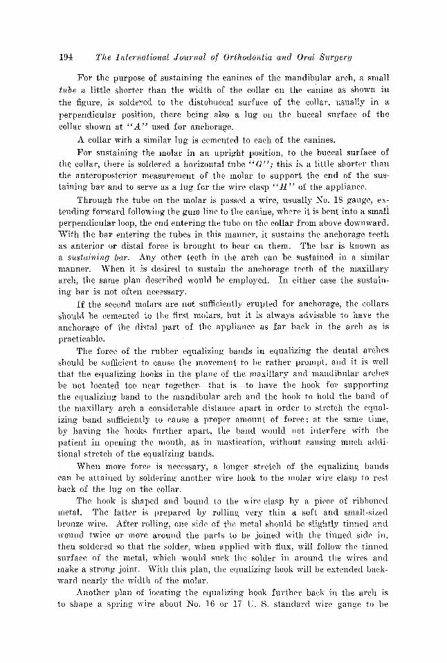
194 The International J ournal of Orthodontia and Oral 8m'gery
For the purpose of sustaining the canines of the mandibular arch, a smalltube a little shorter than the width of the collar on the canine as shown inthe figure, is soldered to the distobuccal surface of the collar, usually in aperpendicular position, there being also a lug on the buccal surface of thecollar shown at "A" used for anchorage.
A collar with a similar lug is cemented to each of the canines.
For sustaining the molar in an upright position, to the buccal surface ofthe collar, there is soldered a horizontal tube" G" j this is a little shorter thanthe anteroposterior measurement of the molar to support the end of the sustaining bar and to serve as a lug for the wire clasp"H" of the appliance.
Through the tube on the molar is passed a wire, usually No. 18 gauge, extending forward following the gum line to the canine, where it is bent into a smaliperpendicular loop, the end entering the tube on the collar from above downward.With the bar entering the tubes in this manner, it sustains the anchorage teethas anterior or distal force is brought to bear on them. The bar is known asa sustaining bar. Any other teeth in the arch can be sustained in a similarmanner. When it is desired to sustain the anchorage teeth of the maxillaryarch, the same plan described would be employed. In either case the sustaining bar is not often necessary.
If the second molars are not sufficiently erupted for anchorage, the collarsshould be cemented to the first molars, but it is always advisable to have theanchorage of the distal part of the appliance as far back in the arch as ispracticable.
The force of the rubber equalizing bands in equalizing the dental archesshould be sufficient to cause the movement to be rather prompt, and it is wellthat the equalizing hooks in the plane of the maxillary and mandibular archesbe not located too near together-that is-to have the hook for supportingthe equalizing band to the mandibular arch and the hook to hold the band ofthe maxillary arch a considerable distance apart in order to stretch the equalizing band sufficiently to cause a proper amount of force; at the same time,by having the hooks further apart, the band would not interfere with thepatient in opening the mouth, as in mastication, without causing much additional stretch of the equalizing bands.
When more force is necessary, a longer stretch of the equalizing bandscan be attained by soldering another wire hook to the molar wire clasp to restback of the lug on the collar.
The hook is shaped and bound to the wire-clasp by a piece of ribbonedmetal. The latter is prepared by rolling very thin a soft and small-sizedbronze wire. After rolling', one side of the metal should be slightly tinned andwound twice or more around the parts to be joined with the tinned side in,then soldered so that the solder, when applied with flux, will follow the tinnedsurface of the metal, which would suck the solder in around the wires andmake a strong joint. With this plan, the equalizing hook will be extended backward nearly the width of the molar.
Another plan of locating the equalizing hook further back in the arch isto shape a spring wire about No. 16 or 17 U. S. standard wire gauge to be
The J ackson R emovable Appliance 195
attached to the lingual side of the appliance and to extend backward as f aras desired, then bent in a curve to the buccal side of th e arch, wher e an equalizing hook is attached to rest in line with the buccal side of the molars.
To increase the force of the equalizin g bands before th e permanent caninesare er upted, it is somet imes ad visable to attach a ri gid wire extension to thefro nt part of the apparatus. This is usually arran ged t o pass through thespace caused by the loss of a deciduous canine or a deciduous molar to thebuccal side and to extend for ward as far as th e lat eral in cisor and th ere havean equa lizing hook attached. In this case, the f ront par t of the appliance isto be retained to one of the teeth, as a premolar or a deciduous molar, by alocking device in th e usual way. When not sufficiently well sustained in thatmann er, a collar with a suitable labial lug for its sup port should be cemented t othe lateral incisor.
Occasionally, for an chorage, when several of the deciduous teeth in thefront part of the arch are absent, equalizing hooks are attached to the loopsof a semicir cular spring th at is arranged to pass in front of the incisors. Thissp ring is r etained by a colla r with a labial lug, cemented t o each of the lateralincisors. 'When this form of apparatus is used, generally a lin gual semicir cular spr ing is adjusted to prevent the in cisors from bein g forced backwardin th e arc h as labi al equa lizing force is applied. Th ese extensions are appli cable to each arch for causing greater force and are necessary in certainclasses of cases.
As a greater or less for ce is often required, it is advisable to keep in st ockequalizin g bands of the same size but of different tensions.
In expanding th e arch laterally, as previously described, or in movin g thet eeth too rapidly, they are liable to become tipped outwar d abnormally. Thisis often noticeabl e as in movin g th e canines laterally outward in providingmore space for maxillary irreg ular in cisors. The tipping can be easily preventedand th e teeth moved bodily by th e anchorage-lockin g device descr ibed. A sp uror shelf of plate met al , such as has been recommended, is att ached to the lingualside of the collar us ed for an chorage at the gum line. Th e apparatus is madeto rest on the lingual shelf, and the wire clasp extending from the apparatus,is shaped to rest abov e the buccal lug on the collar as shown.
Fig. 9 and Fig. 16 A. By this arrangement, th e appliance resting on thelin gual shelf and th e wire-clasp extending to th e bu ccal side of the tooth andpulling on the lu g, th e canine is held in a perpendicular position as force isapplied in moving it bodily outwar d. If at any t ime the canine is not sufficiently perpendicular, the end of th e wire-clasp can be made to pull harderon th e bu ccal lu g and so for ce th e root more bodily outward, or the forcecan be gauged to give the canine the position desir ed.
In a similar manner , a premolar or a molar can be moved outward bodily,by having the appliance rest on the lingual shelf attached to the premolar ormolar colla r and the wir e clasp, shaped to extend from the appliance back of themolar to th e bu ccal side to pull on the bu ccal lu g provided. Added force iscaused by bending from t ime to t ime the end of the wire clasp so it may pullharder on the lu g.
196 T he In ternational J ournal of Orthodont ia and Oral Surgery
In equ alizing the dental arches anteroposter iorl y, when there is a considerable force on th e mandibular molar caused by th e st re tch of the equalizingband pulling forward and upward on th e lug of th e collar, it somet imes tend s tot ip t he cr own of the molar inwa rd and the apex of the root outward. Whenthis occurs, it is r ead ily prevente d by solder ing a lingual lu g on th e collarfac ing gingivally , and shaping the appliance to catch underneath th e lu g. Atth e same t ime, a wir e clasp that extends fr om the appliance back of the molar,is fitt ed t o rest or press on the upper surface of a buccal lu g provid ed for ri ghting the position of the molar. W hen desired, as in equalizing th e dent al arches ,th e end of the clasp can terminate in an equa lizing hook for holding an equalizing band.
For promptly tipping the tooth more upright, the buccal portion of thespring is bent downward to press more heavily on the buccal lug, while both
F ig. 20. F ig. 21.
th is force and the force of th e equalizing band is lifting upward on the linguallu g.
In such a case, the wire clasp would be made of larger wire than usualt o be sufficiently stiff promptly to cause the necessary force ; the force bein g'governed according to th e desire d amount of bodily movement of the root ofthe molar, so as to give it a more upright positi on.
The same principl es of anc horage would apply in either of the cases descr ibed, and is applicable for caus ing th e similar move ment of any teeth inth e arch.
When the molar wire clasp is properl y ad justed for anchora ge, the or dinary force in regul ating seldom changes the positi on of the molar.
In furth er considering th e subject of the equa lizing of the dental arches,we shall examine th e facial features of one or more cases and call at tenti on tosome ne cessary point s in th eir di agnosis. In cases of maxill ar y protrusion, it isalways ad visable to examine care fully the facial line and det ermine whetherthe mandible is sufficiently prominent, or whether it should be made more
The J ackson R emova ble Appliance 197
prominent. (Fig. 20.) This is usually de te rmined by the st udy of the profile facial line, by holding upright with the hand t oward -the patient, a smallpencil or st raight-edge, and sight across it so that the line from the eye willr est on the forehead and, at the same t ime on the p oint of t he chin, and f romthis de ter mine whether the chin is sufficiently prominent or too prominent
Fig. 22.
F ig . 24.
Fig. 23.
F ig. 25.
to compare with the line of the for ehead and balance well wit h the featu res.In this case it was determined f rom examin at ion that th e mandible was pract ically promin ent enough. In order to demonstrate this principle more fully,it is usually wise to ask the pati ent to move the mandible forw ard as much aswould permit t he mandibular teeth to in te rdigitate with th e teeth of the maxillary arch as shown in F ig. 21, from whi ch it will be seen by examining thechanged facial line that both the mandible and the maxillary arch would be
IDS The International Journal of Orthodontia and Oral Sllrgery
much too prominent. Therefore, for the correction of this condition, it requires more particularly, the reduction of the prominence of the maxillaryarch and, accordingly, in equalizing the arches in this case, the lateral maxillary divisions of the maxillary arch should first be moved backward sufficiently to occlude properly with the teeth of the mandibular arch. With ourplan of equalizing the dental arches, this is easily accomplished, as all of themandibular teeth would form an anchorage for moving backward in the lineof the arch, a less number of teeth in the maxillary arch, as the molars, premolars and canines, until they rest in normal occlusion with the teeth of themandibular arch. The prominent maxillary incisors should then be moved inward to occlude properly with the mandibular incisors by attaching a semicircular spring with loops to the apparatus for the purpose, thus reducing theprominence of the maxillary arch. The intermaxillary force employed shouldbe continued to counteract the force of the labial springs in moving the incisorsinward.
There is a vast variety of neglected cases that should be treated by the
Fig. 26.
orthodontist. He is sometimes called upon to meet extreme conditions. Figs.22 and 23 illustrate an important example of a trying case. By studied treatment, marked improvement was brought about in the facial lines and in theocclusion, as shown by Figs. 24 and 25.
CHANGES IN THE MANDIBLE
In equalizing the dental arches, anteroposteriorly to any extent, there arealways changes taki.ng place in the shape of the mandible, principally at thelocation of the angle, caused by the necessary intermaxillary force.
It is essential that all details of this movement and changes caused byequalizing the arches be understood by the orthodontist. It is important tohim in the diagnosis, the laying out of a general plan of treatment and indicating in the different stages the best method to pursue; as an example, when themandible arch has distal occlusion, with the incisors antagonizing with the gumjust back of the maxillary incisors, or a case with moderate distal occlusion.This condition has been successfully treated by utilizing the normal occlusal
The J ack son R em ovable Appliance 199
fo rce in depressin g th e lower incisors and, at the same tim e, chang ing th e shapeof the mandible by adding to an upper r egulat ing appliance a m etal shelf atta ched to the arms of the appliance. The shelf is shaped to fit the lingual cur veof the incisor s and project backward enough so that the lower incisors, when inocclusi.on, would rest upon th e shelf, not permitting th e molars and premolarsto occlude.
In such a case, th e applian ce should be well an chored and support ed toresist the force in masti cation. (F ig. 26. ) F or the lat ter , a loop ed springwire should be sha ped to pass around the tapered cusp of each of the uppercanines, and r est near the mesial and distal surfaces, with the ends of the. wiresexte nding toward the gum passin g underneath the shelf to whi ch they are soldered. With this arrangement, th e shelf is strongly supported and, when tlie
Fig. 27.
appliance is kep t consta ntly in place, would gra dually change the ang le of themandible through th e force caused by the action of the mandible in attemptedmasti cation with th e six mandibular anterior teeth rest ing on th e shelf in occlusion, with non e of the oth er t eeth occluding. The shelf is somet imes madelevel, but when the arc hes need equa lizing, it is ti pped forward more or less sothat, when th e mandibular in cisors rest upon th e incline of th e shelf, th ey wouldslide forward drawin g forward on the mandibular arch. In occlusion this for ce,in effect , downward and forward on the anteri or part of the body of the mandible gradually cau ses the angle of the mandible to become more obtuse andthe body of th e mandible to move farther forward, th er eby t ending t owardnormal occlus ion.
This change in th e an gle will be better und erstood by reviewin g th e plan
200 The International Journal of Orthodontia and Oral S1[rgery
of the development of the mandible and later by its treatment. With theyoung child the ramus is short and the body of the mandible is short. Thebody of the mandible in its further development gradually becomes longerfrom the symphysis to the ramus to accommodate each developing deciduoustooth in its regular order of eruption and continues its development to accommodate each of the erupting permanent teeth in their successive order. Theeruption of the third molar seldom occurs before the age of 18 to 21 years.During this time the ramus portion of the mandible is undergoing a similarprogressive development at the angle, contributing to the length of the bodyand ramus. By this it will be understood that the region at the angle of themandible is in a constant developmental stage from the beginning of the life
Fig. 28.
of the child to that of the adult, and accordingly, its cellular arrangement duringthis period is more easily changed by any steady, constant force.
The anatomical changes in the mandible from infancy to old age must always be kept in mind in our diagnosis. The angle of the ramus and body ofthe mandible in infancy is obtuse and through normal development of thebody and the ramus it gradually becomes more nearly a right angle aboutthe adult period or later, but as one advances in life, the angle of the mandibleagain becomes more obtuse.
Fig. 27. In continuing, cases with more defined distal occlusion requirein their correction, intermaxillary force for the equalizing of the dental archesby the use of rubber equalizing bands. As stated, in bringing about normalocclusion, one should fully understand the changes that are to take place inthe form of the mandible. In masticating, the normal movement of the angle
The Jackson Removable Appliance 201
of the ramus portion of the mandible backward and forward scribes a section
of a circle. When the mouth is opened, the angle of the ramus approaches thelowest point of the circle and, when the mouth is closing, the angle of the ramusmoves forward in the circle to a higher level. The continued equalizing forcein moving the teeth forward to correct the distal occlusion gradually bendsand raises the distal part of the body of the mandible and molar teeth upwardto a higher level in relation to the incisor teeth which generally antagonizewith the gum back of the maxillary incisors, in effect, bending the forwardpart of the body of the mandible downward. As this is done, the mandibularmolars are caused to occlude further forward to a normal position in relationto the maxillary molars by the ramus becoming more obtuse; also the mandibularincisors are brought to a lower plane to occlude normally with the maxillary in-
Fig. 29.
cisors (Fig. 28.) This is caused by the lower end of the ramus with the bodyof the mandible being drawn forward by the force of the equalizing bandsattached to the apparatus opposite the maxillary canines and to the distalmandibular molars, the force of which bends the mandible at the angle, thuscausing the ramus to take a more obtuse angle in its relation to the body ofthe mandible.
Through these changes, the ramus retains the same normal temporomandibular articulation through the normal action or strain of the muscles and ligaments, while the lower end of the ramus that joins the body of the mandible,swings forward and upward in the circle as in the act of mastication. The circlethat it scribes represents the length of the ramus from its articulation to theangle where it joins the body of the mandible. As the lower end of the ramus atthe location of the angle is drawn forward by the force on the teeth in equaliz-
202 The I niernatioual Journal of Orthodontia and Oral Surgery
ing the arches, it will be not ed that it swings the lower end of the ramus inthe line of the circle; this raises the body to a higher level and th e farth erthe teeth and body of th e mandible are moved forward by this force, the morethe mandible is bent at th e angle.
In equalizing the dental arches anteroposterior-ly, it sometimes occurs thatthe continued force in equalizing would cause the angle of the mandible tobecome too obtuse, resulting in the front part of the body of th e mandible beingbent downward more than it should be, often causing lack of anterior occlusionof th e teeth, and at the same time if the force be further continued, it wouldcause the body of the mandible to move forward too far, tending toward a prognathus condition. (Fig. 29. )
This generally results from a mistake in diagnosis and treatment, as thebody of the mandible should not be moved forward in any case during theprocess of equalizing more than to gain a normal occlusion and a good profile.In equalizing, if lack of anterior occlusion of the teeth is taking place, the equalizing should be discontinued and the mandibular arch sustained, while the te ethof the maxillary arch should be forced backward more to bring about the desired normal occlusion.
In eases when there is a moderate lack of anterior occlusion, th e teeth can
e
Fig . 30.
be readily elevated for it s cor r ecti on by cementing a collar with a labial hookto each of the teeth exhibiting lack of occlusion and extending a wire fingerspring from the appliance, usually at the junction of the first premolar andcanine to the buccal sid e of th e arch, shaped to follow forward in the curve ofthe arch to rest in the hooks on the collars provided. The spring should bebent downward from time to time for the purpose of elevating the teeth asdesired. (See Fig. 30.)
POI' additional force, a collar with a hook-shaped spur pointing downwardcan be cemented to one or more of the mandibular in cisors on the canines andan equalizing band of small diameter be applied to the hooks arranged in themaxillary and mandibular arches, or the band be passed over the spring extending from the appliance and stretched to the hooks of the opposite arch. 'Whenthe arches have been equalized and the front teeth elevated, they gen erallyrequire long retention.
In the correction of lack of anterior occlusion of the dental arches, whi chgenerally improves the appearance, it should first be determined from theaction of the patients' lips, when smiling, whether the maxillary or the mandibular teeth with their sockets should he elevated. A method that has been common
Th e J ackson R emovable Appliance 203
in practice with the writer for a cons ide rable number of years in eleva t ing thet eeth for lack of occlusion , as of four incisors, and at t imes including th e caninesand, when necessary, th e premolars and molars, is to cement a collar with alabial hook to each of th e teeth to be elevated. F or th e mandibular arch, thehooks should point downward, and for the maxill ar y arch, they should pointupward.
Th e hooks are mad e of plate metal and the ends mad e long enough to bendaround a labial bar. (F ig. 30.) Th e bar of 19 or 20 gauge is cur ved and rest sin' th e hooks p rovided, and th e hooks are mad e long enough to be bent aroundth e bar to clasp it when in place. An applian ce with a palatine base wirestrongly anchored, as described, has a spring-wire arm extending from theappliance over the arch at the junction of the canine and premolar and extends forward on the labial side close to the teeth near the gum where the armterminates in a side bend to hook over the bar and baek of it, between the centralan d lateral incisor, one ar m on each side of th e arch. 'I' he arms are to be bent
F ig. 31. F ig. 32 .
downward or upward, a lit tl e at a time once a week as required for the elevat ion of the teeth. The applian ce is readily removed by unhooking the springsfrom the bar. This is convenient both for the patient and the operator. Theplan is especially suited for moving the teeth and for th eir long retention. Anappliance of a similar plan is utilized for th e depression of incisors.
Cases of true prognathism accom panied with lack of anterior occlusioncan usua lly be corrected by the uninterrupted application of exte rnal for ce onth e mandible over the mental process at the symphysis by the use of a chin capand cranial cap, causing th e ramus to become less obt use, permitting the bodyof the mandible to bend upward with the in cisors, br ingi ng about normal ocelu sion.
A SPECIAL FO Rl\[ OF A REl\WVABLE REGULATING APPLIAN CE
Th e applia nce t o be descr ibed is arranged for th e t reatment of a case withnarrow maxillary arc h with prominent canines, the lateral in cisor s now resting near the first pr emolars, requiring the genera l expa ns ion of the arc hfor the full accommodation of th e canines and establishment of good occlus ion.
204 The International Journal of Orthodontia and Oral Surgery
For anchorage, Fig. 31, there is soldered to a collar a U-shaped piece ofplate metal or a small loop of wire about No. 16 with two short projecting armsor spurs extending lingually, one above the other. One arm is slightly longerthan the other to act as a shelf for sustaining the base wire of the appliance, theshorter one holding it in position.
These spurs often in the form of a wire loop are generally attached to thelingual side of a collar cemented to each of the anchorage teeth, usually thefirst premolar and distal molar on each side of the arch, the loops in thiscase being attached to the collar rather near the junction of the teeth to permitthe base-wire of the appliance, when in place, to rest on the surface of thecollar and side of the anchorage teeth.
Fig. 32. With an appliance anchored in this manner, tubes for supportingsprings for moving individual teeth can be attached to any part of the basewire, or the springs be soldered directly to the base wire. Th3 appliance canbe easily removed for making necessary changes and readily readjusted.
'With the appliance illustrated, a tube is soldered to each arm of the basewire for sustaining the ends of the lingual semicircular spring with U-shapedloops. To the semicircular spring back of the central incisors at the medianline is soldered a small additional curved spring with the ends projecting likearms resting on the lingual side of the central incisors and laterals with theends terminating on the distal surface of the latter. The free ends of thespring or arms are bent outward from time to time for moving the lateralsoutward and forward, while all of the incisors are forced forward as desiredby opening the loops of the semicircular spring. At the same time, the arch isbeing expanded laterally by opening the loop of the base wire.
Fig. 33 outlines the full plan of the appliance. It is readily removed fromthe teeth by grasping one arm opposite the second premolar and forcing itlingually a little to unlock it from the spurs on the collars described. As theappliance is removed, the semicircular spring can be withdrawn from the tubesto permit any necessary change of form of the spring or of the base wire. Theappliance is readily readjusted to the teeth by placing one of the arms of thebase wire into the U-shaped supports on one side of the arch, pressing in thatdirection on the other arm of the appliance to lock it in the U-shaped supportson the other side of the arch.
ANOTHER FORM OF ANCHORING APPLIANCES
A desirable plan of anchoring a removable appliance with tubes or eyeletson collars cemented to anchorage teeth, having any form of base wire to whichsprings may be attached is given below.*
"When one is accustomed to the use of collars for anchorage, this system isutilized by anchoring a base wire as follows: A collar, wi.th a tube solderedon the lingual side, is cemented to a distal molar and to one of the bicuspids oneach side of the arch. The tubes can be arranged on the collar at any anglevarying from the horizontal to the perpendicular. A heavy lingual or palatinebase wire is held in place by soldering to it a small, strong wire in position to
"Jackson's Orthodontia, page 88.
The Jackson Removable Appliance 205
enter the tubes. 'Wires entering the tubes on the molars are sometimes arrangedto hook into the tubes from the distal end, while similar wires are attachedto the base wires to enter either horizontal or perpendicular tubes on thebicuspids. When tubes are arranged perpendicularly on the collars, they aregenerally inclined a little either forward or backward to improve the anchorage,so that when force is applied, the apparatus will not become dislodged. A labiobuccal base wire is anchored in a similar manner. When desirable, all of thetubes can be arranged perpendicularly. The anchorage teeth are prevented fromrotating, when extreme stress is put upon them, by soldering the tubes on the
Fig. 33.
mesio-lingual or the disto-lingual surface of the collar, according to the strain
to be applied."The author has endeavored to present in this paper the more important prin
ciples of his system of orthodontia and trusts that the suggestions may be of
permanent value.DISCUSSION
Dr. L. J. Porter, New York City.-I had the privilege of looking over Dr. Jackson'spaper although I shall not attempt to discuss it, because I feel that I am incapable of discussing thc principles of the Jackson appliance from the little experience I have had withit. However, there is one question which I would like to hear discussed, and that is thequestion of changing the angle of the mandible. I think it has been said by some of thebigger men in our profession that in carrying the mandible forward, the condyle will slideforward in the glenoid fossa. If that is true, we can show better by Dr. Jackson's apparatusthere what I mean. If the whole mandible is carried forward, will not the condyle slideforward in the glenoid fossa ~ If the mandible is held in position and the lower part of themandible is carried forward, the angle of the mandible undoubtedly changes, but if themandible at the same time is being carried forward in the glenoid fossa, will not the anteriorteeth resting on that bite plate be depressed before the angle of the jaw is changed by muscular
action before the elastic ligature is used ~
Major Joseph D. Eby, Washington, D. C.-There has been a most peculiar sense ofpleasure and feeling of gratitude mingled in my thoughts which I have enjoyed while sittingin this audience and following Dr. Jackson in his paper, after three years away from activeorthodontic practice although busily engaged in work involving the active principles of the
science.My thoughts, the while, have been racing back through the vista of fifteen years' as-
206 The Lniernaiional Journal of Orthodontia and Oral S11rgery
sociations with Dr. Jackson's system employed in active practice, recalling his many actsof kindness, his glowing friendship, what his work has really meant to me and-the thousands
of his appliances which I have made.
It would be inappropriate at this time to dwell on the evolution of orthodontic appa
ratus further than to call attention to some points which are relevant to this paper; viz,
the fact that present-day working apparatus can be no longer classed into the two formerdivisions-' , Fixed" and "Removable."
Our present knowledge of the correct control of tissue changes in the physiological
processes attending tooth movement by mechanical stimulation has substantiated the active
principle which Dr. Jackson recognized in his first efforts to produce an apparatus employingthe accurately measured lib era tion of spring and elastic forces.
Science is solving the question of the dynamics of orthodontia so that progressivethoughts must turn from autocratic and arbitrary ideas and become centered, not upon thekinds of forces to use, but upon the questions of anchorage, design and control of stimulation,not power, the very thing which the Jackson system has embraced for years.
N ow since modern progress has brought practically all useful appliances to meet onthis common ground, the fact exists that Dr. Jackson's present apparatus are equally asstable in anchorage, stationary in applied stimulation and none the less dependent upon thepatients' cooperation than any other appliances using adjustable springs, contemporaneouspoints which have been until recently generally acclaimed as disadvantages.
Mechanically, the modern Jackson apparatus requires a mastery in technic of construction, more so, perhaps, than many other appliances which embody similiar principles butwhen once the skill is developed by the operator, the following advantages are to be
found:1. Relative ease of construction.2. Great latitude of design.3. Ease of insertion.4. Exact control of stimulation.5. Ease of alteration to meet advanced conditions.6. Durability.7. Favorable location.8. Remarkable balance between the problems of anchorage and applied forces.9. Comfort to patient and operator.
10. Accurate control and adjustment.11. Hygienic.12. Volume and quality of production.13. Excellent retainer.14. Aids the forces of occlusion.There are many other salient points about Dr. Jackson's appliance, one other, at least,
to which I desire to call special attention: In the majority of malocclusions, there are certain segments in arches, particularly in the posterior regions, wherein certain groups of teethare in correct relations and if they are shifted en masse, the phenomenon produced in thealveolus is altogether different from that made by an appliance which ads against the teethindividually.
In the Jackson apparatus, the 'side arms or the extended "finger" springs may bemade to engage groups of teeth so as to transpose them in a block movement.
Radiographic observation of this condition invariably reveals the fact that the socketlining, the lamina dura, or the pericemental lamella, remains intact and tooth movement results from the absorption of more cancellous alveolus adjacent. In comparing this advantagewith individual tooth movement, some of the following facts are suggested:
1. Movement expedited.2. Teeth retain alignment.3. Dentinal ligament, peridental membrane, laminated socket lining uninjured.4. Retention more rapid and assured.
The Jackson Removable Appliance 207
It seems to me that this is a point in tooth movement to which due regard has notbeen paid, should be one of the most important points in selective design of apparatus and
in arch stimulation particularly, is practically idealized in the Jackson system.
'I'he observations which Dr. Jackson makes in the changes occurring through the angle
of the mandible in equalizing the occlusion, whether by anterior or posterior movement of the
mandible are correct to my mind and the manner in which he has demonstrated it with thediagrammatic model is most unique.
I first awoke to the full realization of this truth after hearing a paper read by Dr.
Chalmers J. Lyons entitled "Impacted Lower Third Molars" in which he elucidated thispoint beautifully from the standpoints of development and the causative agencies which pro
duce the condition of impaction.
One of the most substantial points to consider is the fact that the ramus is composed
of two very heavy plates of corticle bone with very little medullary process between them
and is posed to best resist any transitory changes ill response to mechanical stimuli made
either anteriorly or posteriorly.
It is true that the neck of the condyle is made of cancellous bone but this is onlyevidence to the fact that owing to its heavy investiture in connective tissue (being fracturedmuch less frequently than the angle) makes it far more resistant than at that point wherethe ramus and body merge. Dr. Jackson's observations in changes at the angle have beenfurther demonstrated (painfully) in the follow-up treatment of numerous gun shot woundsthrough the angle in which soldiers had worn "open-bite" splints for several weeks, in allof these cases where solidification had taken place, an artificial prognathism and open-bitenonocclusion existed, requiring tedious orthodontic treatment to correct.
This fact in its simplest interpretation, demonstrates that the elevating and depressingmuscle groups must be reckoned with and that the angle is the center of compensation between them.
If it is remiss for maf.o depart from the thoughts in the paper, I desire to receive indulgence while I express a thought which has weighed very heavily in my mind for severalyears and in so doing, I am sure I am expressing similar feelings of hundreds of others.
Since the publication of the first edition of Dr. Jackson's book, he has so completelyrevolutionized so many parts of his system until the orthodontic world is asking for knowledge which can only be gained in glimpses when Dr. Jackson presents something personally. If, instead of devoting his life to the comparative few whose privilege it is forhim to serve, he would only produce a modern illustrated text in the form of his secondedition, he would record for our profession and to human kind a contribution, not only neededat present, but by the generations to come, thereby engraving his name more everlastingly intodental history and gaining the fullness of the reward which his great life's work so noblymerits.
Dr. William H. Gilpatric, Boston, Mass.-I have a set of slides illustrating the different apparatus and their various movements, but the hour being so late, and not wishing toencroach upon Dr. Case's paper, if you will allow me, I will show one or two eases illustratingthe different types of movement and have the remainder printed in the Journal.
One point Dr. Jackson did not emphasize, and that is the importance of registeringpressure applied to any appliance. It is my opinion that with every appliance used, weshould be able to control the forces, and know the amount of tooth movement in a given time.
Another point which Dr. Jackson did not lay sufficient stress upon is the importance ofusing large base wires and large finger springs. It was my opinion, at one time, that Dr.Jackson was using too heavy a base wire and finger springs, but after a thorough trial withsmaller ones, I am convinced that the heavy base wires and finger springs, which he recommends, are superior for cell stimulation. Some of the men who are unfamiliar with the Jackson appliance criticize the heavy base wires on account of bulk, but in the past fifteen years,I have used the Jackson appliance in the mouths of physicians, teachers, and vocalists, andhave never had a complaint.
208 The International Journal of Orthodontia and Oral Surgery
One of the great advantages of the Jackson appliance is the ease with which repairs
and additions can be made.After the appliance is made, we gold plate it with 24 karat gold, and on each appoint
ment, the patient's appliance is immersed in a saturated solution of cyanide of potassium.During the past few years, there has been a great land-slide towards the removable
retainer. A retainer of this type is more easily constructed, more easily adjusted, and lessliable to breakage than the vulcanito.
Fig. 1. Fig. 2.
Fig. 3. Fig. 4.
..
Fig. 5. Fig. 6.
The slides which I shall show are of practical cases, made from working models, that is,
after the appliances are constructed, we photograph both models and appliances, beforeplacing the latter in the mouth.
Fig. 1 illustrates an appliance with a loop to open up space for an impacted secondbicuspid and to move the first bicuspid and cuspid mesially. The anchorage for the applianceis obtained from the left six-year molar, first and second bicuspid and cuspid. On the right,from the six-year molar.
The Jackson Removable Appliance 209
Fig. 2 illustrates the new Jackson anchorage so-called, although Dr..Jackson has used
this for the past 15 or 20 years. The upper has collars upon the six year molars and the tem
porary cuspids. The lower has the same anchorage.F'ig. 3 illustrates the appliance constructed upon the model. (Note the inside semicircle
against the centrals.)
, ,
-...... '
-.
~ .I
,...... "
."... ~
Fig. 7.
Fig. 9.
Fig. 11.
Fig. 8.
Fig. 10.
Fig. 12.
Fig. 4 illustrates the models in occlusion, appliances in place with the intermaxillary
rubbers. (Note the labial wire on the lower to relieve pressure from temporary cuspids.)In these mesial occlusion cases you have the resistance of four teeth on each side plus
the two centrals as the palatal wire rests at the gingival margin and the labial wire at theinside edges.
210 The International Journal of Orthodontia and Oral Surgery
Fig. 5 illustrates the ease of a young man 19 years of age with excessive overbite sothat in masticating his food he was shearing off his lower anterior teeth.
Fig. 6 shows palatal view of same.
Fig. 7 shows lingual view of lower.Fig. 8 shows the surveys of the upper and lower arch, on the left side, right side, prog-
ress to date.Fig. 9 shows the palatal view of the same case to date.Fig. 10 shows lingual view of lower.Fig. 11 shows models in occlusion. Note the change in overbite due to the tipping bue
cally of the lower molars and bicuspids, and the correct moulding of the upper and lowerarches.
Fig. 12 illustrates appliance for the expansion of the upper and the bringing together ofthe centrals.
Fig. 13 shows appliance upon a lower model with individual finger springs for individualmovement of the bicuspids.
Fig. 13. Fig. 14.
Fig. 15.
Figs. 14 and 15 illustrate a retainer to retain the molars and bicuspids with a labialwire to prevent the anterior teeth from moving mesially.
There is a final point I wish to emphasize and that is, in case too much force is applied,the appliance can be removed.
I wish to express my gratitude to Dr. Jackson for all the inspiration and help he hasgiven me. I assure you it was a great honor to have the privilege of being associated withhim in his office.
Dr. Jackson (closing the discussion).-In replying to Dr. Porter's question: "If thewhole mandible is carried forward, will not the condyle slide forward in the glenoid fossa ~"
This is an important question and should be thoroughly considered and understood.It is nature's plan that the condyles of the mandible be held back in the glenoid fossa as faras they can rest through the action of the sustaining musclcs.
In incising the food and, in speaking, the mandible is necessarily moved forward bythe action of other muscles as required, which puts the sustaining muscles on the stretch. Asimilar effect results when equalizing force is applied to the teeth. Continued force for
The Jackson Removable Appliance 211
equalizing the dental arches, drawing forward on the teeth and th? lower end of the ramus,while the sustaining muscles are on the stretch, drawing boclcurard on the condyloid portionor upper end of the ramus, grac1uaJly causes the angle of the mandible to become more obtuse.
In equalizing the dental arches it oceasionally occurs, when this force is applied eontinuously for a considerable length of time, that the sustaining muscles supporting the upperend of the ramus become exhausted from this, a too exacting force, permitting the condyleto be drawn forward as far as the capsular ligament will allow. By this relaxation of thesustaining muscles, the mandible is often permitted for the time, to rest farther forward thanwould be a normal occlusion of the teeth, when by the operator's examination of the occlusion at this stage, finding the mandibular arch resting anteriorly, he might be deceivedby the position of the teeth and conclude that the angle of the mandible may have become tooobtuse, when in fact it had not been changed. This being the case, the equalizing shouldstill be continued, until the angle of the ramus becomes sufficiently obtuse to cause thecondyle to rest normally and, at the same time have normal occlusion of the teeth.
As stated, when the equalizing force is removed and the condyle is fully at rest. itshould normally be held back as far as can be in the glenoid fossa by the sustaining muscles.
In diagnosis, when this is doubtful, the condition should be fully determined by theoperator and, if the muscles are still inactive and it is difficult for the patient to move themandible backward at will, the sustaining muscles are usually brought into action for that
purpose, by inducing the patient to laugh or to swallow, which invariably stimulates themuscles to draw the condyles of the mandible back to a normal position. Then the operatorwould know by examination of the teeth, whether the desired normal occlusion, as required,is being established as result of the angle becoming more obtuse.
Dr. Porter in discussion also asks: "Will not the anterior teeth resting on a bite-platehe depressed before the angle of the jaw is changed hy muscular action, before the elasticligatnres are used ~"
In my paper, I referred to depressing the incisors with their alveoli by the nse of anupper lingual shelf attached to any ordinary regulating appliance, This is an importantmethod of depressing incisors especially for young patients when a moderate change is reoquired.
The angle of the mandible is often changed by this plan of treatment particularlywhen the shelf of the appliance is arranged to project downward and backward, in effect inoeclusion, pressing forward and downward on the mandibular incisors and canines, andwhen used continuously for some time.
When a more excessive change of the angle and depression in the region of the incisors is required, in addition to the occlusal force of the mandibular teeth on the shelf, theequalizing foree should be employed,
Dr, Eby has understood the principles of my plan of constructing aIH] managing regulating appliances so well and from his experience has spoken so enthusiastically about thevalue of the plan that I desire to commend his discussiou. I am pleased that he has masteredthe suhject a nd has prescnterl it so t horoujrhly in his teaching, that he has an unparalloledfol!<hving of enthusiasts.
Dr. Gilpatric's presentation and discussiou is in fuJI keeping with the purpose of mypaper and I want to thank him and each of the speakers for their thoughtful and kind consideration of the subject and of me, I have he en extremely anxious to so perfect my appliancesthat their use may conduce to the true welfn re of humanity.