50 IEEE TRANSACTIONS ON INDUSTRIAL ELECTRONICS AND CONTROL INSTRUMENTATION, VOL. IECI-21, NO. 2, MAY 1974 The Problem with Programmable Controllers D. L. SMITH Abstract-The problem with programmable controllers is that a pushbutton), the motor starter breaks into oscillation. there are so many on the market today. It is very difficult to make a This happens because on the next scan through program, choice on the basis of sales literature, because the advantages and . ' . ~~~~the output iS turned OFF as a result of not having the problems are not obvious. It is the intent of this paper, therefore, to theutput i r OFF stares of not h n the examine some of the characteristics of the various programmable pushbutton input or the starter contact input. On the controllers and see how they compare for different applications. next scan, the output is turned ON because the inertia of the starter armature carried it through and made its MEMORY CAPACITY contact. At this time, the output is OFF so the starter armature falls back, but contact was made when the con- When is 4 K like 2 K? Depending on the control and its troller started its scan. At the end of the scan the output program format, a "word" could contain only an instruc- turns on, repeating the cycle. tion or an address. Therefore two words would be required to program the command and the address. Another con- MODIFYING PROGRAMS troller may have the instruction and the address in the Presently there are five different memory systems being same word, thereby effectively doubling its memory used in programmable controllers, each with its own pro- capability when compared to a controller with single- gram-changing problemns. Toroidal core (read/write) and function words. So, when analyzing a controller for plated wire (ROM\ alterable) mlemories can be altered memory capacity, find out what the manufacturer means easily as long as the number of words in the new program when 4 K capacity is advertised. The example given used segment does not increase from the original nunmber of a 2: 1 ratio just to demonstrate a difference. In actuality, words. If the number of words in the new program is four instructiorns on one controller may take seven in- increased, the program segment must be put in an empty structions on another. area of the memory. A stored field (ROM alterable) memory is repro- SCAN TIME grammed by exposing the memory chip to be repro- Scan time is the total time it takes the controller to grammed to ultraviolet light with a hand-held probe, thus examine its inputs and outputs throughout the program erasing the memory contents. After erasing (30 to 40 and act on the results by turning outputs ON or OFF. -seconds) the chip can be reprogrammed. For example, assume a controller operating a motor- In the diode inatrix (PROM) memory, certain instruc- driven machining slide (mechanical feed unit). The tions may be altered, but this alteration is very limited. machine slide has a rapid traverse brake motor and feed Provision for major program changes can be made by motor, both of which are started simultaneously. The leaving spare spaces throughout the program to use for slide actuates a limit switch which turns the rapid motor minor additions and changes. If a program error is en- off, causing the unit to advance at feed rate. With a unit countered and there are no spare spaces in that program traverse velocity of 420 inches per minute, and a controller segment, the whole segment must be changed to a NO scan time of 40 milliseconds, the unit could travel 0.280 OPERATION code, and then the corrected program inch before the output changed to de-energize the motor must be written wherever there is spare space in the starter. There are two ways to overcome this problem: memory. In one programmable controller, the memory 1) Set the feed switch heavy, thereby wasting valuable chips are removed and plugged into the memory loader production time by frequently feeding an extra 0.280 for altering; and in another, the whole memory board is inch, and 2) hardwire the other half of the feed limit removed and plugged into the memory loader. switch to the motor coil. Many additions and changes may be performed for Another problem that can be caused by scan time normal debugging, and still there is room left over. A arises from using a starter contact on the controller input major change in program (such as retooling a machine) to act as a sealed contact in the program. With a scan necessitates replacing the diode chips on the memory time in the 30- to 40-millisecond range, the controller board and entering the new program. is near the response time of the starter. If the input that The hardwired transformler matrix (ROM) memory is energizes the starter is momentarily put on (by tapping more difficult to alter than the other memory systems, because the tiny wires that are routed through the trans- Manuscript received July 3, 1973. This paper was presented at fre oems epyial eotd hr ao the 37th Annual Machine Tool Forum sponsored by Westinghouse alteration of mwemory is required, it may be necessary to Electric Corporation, Buffalo, N. Y., 1973. replace the memory board with a completely rewoven The author is a Consultant with Bee Control Systems, Warren,bad Mich. 48089. bad
Transcript
50 IEEE TRANSACTIONS ON INDUSTRIAL ELECTRONICS AND CONTROL INSTRUMENTATION, VOL. IECI-21, NO. 2, MAY 1974
The Problem with Programmable ControllersD. L. SMITH
Abstract-The problem with programmable controllers is that a pushbutton), the motor starter breaks into oscillation.there are so many on the market today. It is very difficult to make a This happens because on the next scan through program,choice on the basis of sales literature, because the advantages and.'. ~~~~the output iS turned OFF as a result of not having theproblems are not obvious. It is the intent of this paper, therefore, to theutputi r OFF stares of noth n theexamine some of the characteristics of the various programmable pushbutton input or the starter contact input. On thecontrollers and see how they compare for different applications. next scan, the output is turned ON because the inertia of
the starter armature carried it through and made its
MEMORY CAPACITYcontact. At this time, the output is OFF so the starterarmature falls back, but contact was made when the con-
When is 4 K like 2 K? Depending on the control and its troller started its scan. At the end of the scan the outputprogram format, a "word" could contain only an instruc- turns on, repeating the cycle.tion or an address. Therefore two words would be requiredto program the command and the address. Another con- MODIFYING PROGRAMStroller may have the instruction and the address in the Presently there are five different memory systems beingsame word, thereby effectively doubling its memory used in programmable controllers, each with its own pro-capability when compared to a controller with single- gram-changing problemns. Toroidal core (read/write) andfunction words. So, when analyzing a controller for plated wire (ROM\ alterable) mlemories can be alteredmemory capacity, find out what the manufacturer means easily as long as the number of words in the new programwhen 4 K capacity is advertised. The example given used segment does not increase from the original nunmber ofa 2: 1 ratio just to demonstrate a difference. In actuality, words. If the number of words in the new program isfour instructiorns on one controller may take seven in- increased, the program segment must be put in an emptystructions on another. area of the memory.
A stored field (ROM alterable) memory is repro-SCAN TIME grammed by exposing the memory chip to be repro-
Scan time is the total time it takes the controller to grammed to ultraviolet light with a hand-held probe, thusexamine its inputs and outputs throughout the program erasing the memory contents. After erasing (30 to 40and act on the results by turning outputs ON or OFF. -seconds) the chip can be reprogrammed.
For example, assume a controller operating a motor- In the diode inatrix (PROM) memory, certain instruc-driven machining slide (mechanical feed unit). The tions may be altered, but this alteration is very limited.machine slide has a rapid traverse brake motor and feed Provision for major program changes can be made bymotor, both of which are started simultaneously. The leaving spare spaces throughout the program to use forslide actuates a limit switch which turns the rapid motor minor additions and changes. If a program error is en-off, causing the unit to advance at feed rate. With a unit countered and there are no spare spaces in that programtraverse velocity of 420 inches per minute, and a controller segment, the whole segment must be changed to a NOscan time of 40 milliseconds, the unit could travel 0.280 OPERATION code, and then the corrected programinch before the output changed to de-energize the motor must be written wherever there is spare space in thestarter. There are two ways to overcome this problem: memory. In one programmable controller, the memory1) Set the feed switch heavy, thereby wasting valuable chips are removed and plugged into the memory loaderproduction time by frequently feeding an extra 0.280 for altering; and in another, the whole memory board isinch, and 2) hardwire the other half of the feed limit removed and plugged into the memory loader.switch to the motor coil. Many additions and changes may be performed forAnother problem that can be caused by scan time normal debugging, and still there is room left over. A
arises from using a starter contact on the controller input major change in program (such as retooling a machine)to act as a sealed contact in the program. With a scan necessitates replacing the diode chips on the memorytime in the 30- to 40-millisecond range, the controller board and entering the new program.is near the response time of the starter. If the input that The hardwired transformler matrix (ROM) memory isenergizes the starter is momentarily put on (by tapping more difficult to alter than the other memory systems,
because the tiny wires that are routed through the trans-
Manuscript received July 3, 1973. This paper was presented at fre oems epyial eotd hr aothe 37th Annual Machine Tool Forum sponsored by Westinghouse alteration of mwemory is required, it may be necessary toElectric Corporation, Buffalo, N. Y., 1973. replace the memory board with a completely rewovenThe author is a Consultant with Bee Control Systems, Warren,bad
Mich. 48089. bad
SMITH: PROGRAMMABLE CONTROLLERS 51
Alteration of the ROM-type memory is more difficult ing, replacing, or reprogramming a memory board, thethan the read/write-type inemory, but the ROM offers the documentation must be absolutely current. Depending onadded protection that the instructions will not be altered the control, the documentation could be magnetic oror lost during normal operations. punched tape (s), ladder diagrams, or standard schematics.
These must be updated after every change. If they areINTERNAL TROUBL,ESHOOTING not, and a memory card has to be changed and just one
While most programmable controllers offer some means word is wrong or missing . . . well, remember the storyfor troubleshooting machine problerns, very few offer the about the needle in the haystack?ability to find problems in the control by utilizing the This topic may sound like a study in engineering coin-programming panel or verifier normally used with its con- monsense, but accurate documentation definitely helpstroller. While the ultimate user may have one or two types miniimize the problems (and learning curves) that theof controllers in his plant, the OEM may be working with control user faces!its own probleins and support equipment required to
PROGRAMM1ABLE CONTROLLER SAFETYdebug a system.While debugging a system, one may encouinter a problem Programmable controllers can be dangerous. The object
that appears to be in the program but actually is in the here is not to condemn the controller, but rather to pointequipment, or vice versa, thereby wasting valuable time. out some of their deficiencies and offer suggestions forThis situation can be minimized by having the capability circumventing them.to exercise the controller through its various logic func- Unlike relay or solid-state logic systems, which are com-tions, and by verifying (through a readout on the equip- prised of single-purpose or dedicated components, thement normally used with the control) that the controller programmable controller shares its logic with all inputsis functioning properly. Unfortunately, the present method and outputs. This simply means that a malfunction of thefor handling internal problems is to use an "in plant" central processor, memory, or data bus, can affect allcomputer or a "data phone" to diagnose the failure, or to outputs. If an adequate detection and shut down systemchange cards at randomn if spares of all cards are available. (internal or external to the control) is not provided, un-The ability to isolate a control problem clearly and quickly controlled machine motion(s) can occur which wouldis certainly an advantage, and most programmable con- endanger both machine and personnel. This can be showntrollers could use some improvement in this area. by the following discussion of typical logic systems and
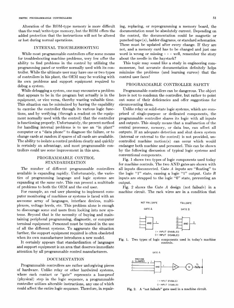
conventional components.PROGRAMMABLEZAONTROL Fig. 1 shows two types of logic components used todaySTANDARDIZATION for machine controls. The two AND gates are shown with
The number of different programmable controllers all inputs disconnected. Gate A inputs are "floating" toavailable is expanding rapidly. Unfortunately, the varie- the logic "1" state, causing a logic "1" output. Gate Bties of programming language and logic systems are inputs are strapped to the logic "0" state, preventing anexpanding at the same rate. This can present a multitude output.of problems to both the OEM and the end user. Fig. 2 shows the Gate A design (not failsafe) in a
For example, an end user planning to implement com- machine circuit. The rack wires are in a condition thatputer monitoring of maclines or systems is faced with anawesome array of languages, interface devices, multi- NOT FAILSAFE FAI LSAFEplexers, voltage levels, etc. This problem alone is enoughto discourage some end users from looking into new sys- GATE A GATE Btems. Beyond that is the necessity of buying and main-taining peripheral programming, diagnostic, or computer _terminal equipment. Personnel must be trained in the use AND 0 AND 0of all the different systemns. To aggravate the situation 0further, the support equipment required is often obsoleted l= INPUT ENABLEDis oftenobsoleted Q~~~O INPUT DISABLEDwhen its own manufacturer introduces a new model. Fig. 1. Two types of logic components used in today's machine
It certainly appears that standardization of languages controls.and support equipment is an area that deserves immediateattention by all programmable control manufacturers. GATE A
DOCUMNENTATION MACHiNE
Programmable controllers are rather unforgiving pieces 3N Aof hardware. Unlike relay or other hardwired systems,where each contact or "gate" represents a loss-proof(physical) step in the logic s;equence, a programmable lINPUTENBEcontroller utilizes alterable instructions, any one of which 0= INPUT DISABLEDcould affect the entire logic sequence. Therefore, in repair- Fig. 2. A "not failsafe" gate used in a machine circuit.
52 IEEE TRANSACTIONS ON INDUSTRIAL ELECTRONICS AND CONTROL INSTRUMENTATION, VOL. IECI-21, NO. 2, MAY 1974
should prevent operation, but the machine clamped con- CARD4, 2SELECTnection to the card is faulty, causing a false output from r 4 LINES
Gate A. If the B-type logic (failsafe) had been used, the 8input connection fault would disable the circuit. The X°
integrity of the rack or interconnecting wires must beguaranteed at all times. 248
Fig. 3 is not an accurate representation of any particular o ocontroller's input circuit; rather, it is in a simplified form S 3I
to demonstrate what can happen to a control. The card 2 2 INPUTselect lines are in the binary code number "one," selecting ETC ETC SELECSthe first input card. The input select lines are selecting the LINH2input "one" on whatever card is selected (in this case, 24card "one"). Yet, because of a faulty connection, card 8number "three" is also being selected. This causes input"one"y on each card to be examined, and in this case appliesfalse information on the data bus line. Due to a faultyconnection, all inputs of both cards will be effectivelyOR (ED) when the memory, together with the processor,interrogates card number "one."
This condition has been known to cause the machineDATA BUS TO
control to go into automatic, start all spindles, and take CARDI CARD 2 CARD 3 PROCESSORoff on its own. The, machine cycled with many of the Fig. 3. Simplified representation of a programmable controller'sinterlocks disabled because the processor wasn't receiving input circuit, showing possibility for dangerous error.
correct information. This problem could be corrected inseveral ways, one of which would be to use a parity check failure. Various manufacturers are presently performing(odd codes to select input and output cards). some of these checks, others are not. Yet, like any otherFailure in the memory, the central processor, and the industry, they need input from OEM's and users. If
data bus circuit, will cause false commands to be given to change in design comes about, the programmable con-outputs. These components can be arranged to check troller will be a more predictable device to control machinesoperations and shut down the control in the event of reliably and safely in the future.
The Design of Brushless DC Motor SystemsJAMES R. WOODBURY
Abstract-In critical applications requiring use of a brushless dc results of this paper should be useful in most small motor applica-motor, the electronics designer is faced with a complex problem. tions in which the motor speeds are sufficiently low that motor wind-The motor typically has at least five independent parameters that ing inductance can either be neglected or compensated simply bymust be specified properly to obtain the best performance. The gear advancing the drive pulse phase as described.ratio must be selected, and in addition, several parameters in theelectronic commutation and control circuitry must be optimized. INTRODUCTION
In this paper the basic control problem is described, the appropriateequations are derived, and a systematic method is outlined for ABRUSHLESS dc motor [1-2] is nothing more than aarriving at an optimum configuration. 1.
It immediately becomes apparent that all applications and possible L5snhoosmtrwt emnn ant,rtemotor types cannot be covered by the same analysis. However, the than electromagnets, used to produce the field. Since the
rotor contains only permanent magnets, no mechanicalManscrptecevedJuy 2, 173;revse Ocobe 11 193.commutator, slip rings, or brushes are required. If a two-
This work was supported by the National Heart and Lung Institute phase brushless motor iS driven from a two-phase sinu-of the National Institutes of Health. sia ore h oo efrseatylk w-hsThe author is with the Electronics and Bioengineering Labora- sia ore h oo efrseatylk w-hs
tory, Stanford Research Institute, Menlo Park, Calif. 94025. synchronous motor. In some cases where more than one