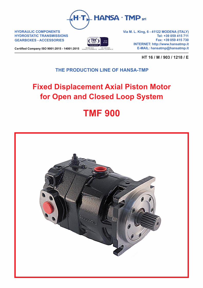
HT 16 / M / 903 / 1218 / E HYDRAULIC COMPONENTS HYDROSTATIC TRANSMISSIONS GEARBOXES - ACCESSORIES Certified Company ISO 9001:2015 - 14001:2015 Via M. L. King, 6 - 41122 MODENA (ITALY) Tel: +39 059 415 711 Fax: +39 059 415 730 INTERNET: http://www.hansatmp.it E-MAIL: [email protected]ISO 9001:2015 Certificate N° 12-Q-0200545-TIC ISO 14001:2015 Certificate N° 12-E-0200545-TIC Fixed Displacement Axial Piston Motor for Open and Closed Loop System TMF 900 THE PRODUCTION LINE OF HANSA-TMP
Fixed Displacement Axial Piston Motorfor Open and Closed Loop System
TMF 900
THE PRODUCTION LINE OF HANSA-TMP
Pag. 3 HT 16 / M / 903 / 1218 / E
Fixed Displacement Axial Piston Motor TMF 900
4
4
5
6 - 7
8 - 10
General Information...........................
������������� ����������������������������
Order Code........................................
��������������������������������������������
Technical Manual...............................
CONTENTS
Pag. 4
Fixed Displacement Axial Piston Motor
HT 16 / M / 903 / 1218 / E
TMF 900MAIN FEATURES
General Information
This is a fixed displacement motor with axial pistons, swash plate design and can be used in closed and open loop systems. The motor was developed for use on hydraulic transmissions, where high speeds and high torques are demanded.The construction features help to minimize the losses due to leakage and considerably reduces the frictions. The small sizes allow easy installation.The motor is equipped with flushing valve integrated on the motor casing which allows thetemperature control, especially in heavy duty applications.
TECHNICAL SPECIFICATIONS
Operating Parameters
Hydraulic Fluid
Filtration
Mineral Oil High Viscosity IndexdiulF ciluardyH dednemmoceR63 ÷ 61tScν*ytisocsiv gnitarepO
Maximum viscosity short term at cold start ν max cSt ≤1600Minimum viscosity at maximum temperature ν min cS ≥7Maximum working temperature of the fluid T max °C 90Permissible temperature range of seals ΔT °C -25 ÷ 120
*Referred to the circuit temperature-closed circuit
It is recommended for an efficient and lasting working life, a solid particle contamination level of 18/16/13 according to ISO 4406. To ensure said level of contamination is not exceeded,filter should be chosen accordingly, with filtration grade of β10 ≥ 2. In any case the contamination level must not be below 20/18/15 according to ISO 4406.
Safety Regulation
This publication provides just an overview of the product and it is addressed to skilled personnelproperly equipped to perform maintenance. During maintenance, assembly and disassembly activitiesuse caution and proper safety equipment, in observance of the rules provided by safety laws.
ATTENTION
The motors are made with heavy parts: secure the parts and use proper lifting equipment.
0110927TMF 900 ledoMDisplacement V cm 3 72 90 110Maximum speed n max rpm 4.100 4.000 3.800Maximum flow q max l/min. 295 340 400Nominal pressure p nom bar 400 400 400Maximum pressure p max bar 450 450 450Maximum power P max Kw 156 180 210Theoretical max torque C max Nm 480 570 700
Pag. 5 HT 16 / M / 903 / 1218 / E
Fixed Displacement Axial Piston Motor TMF 900
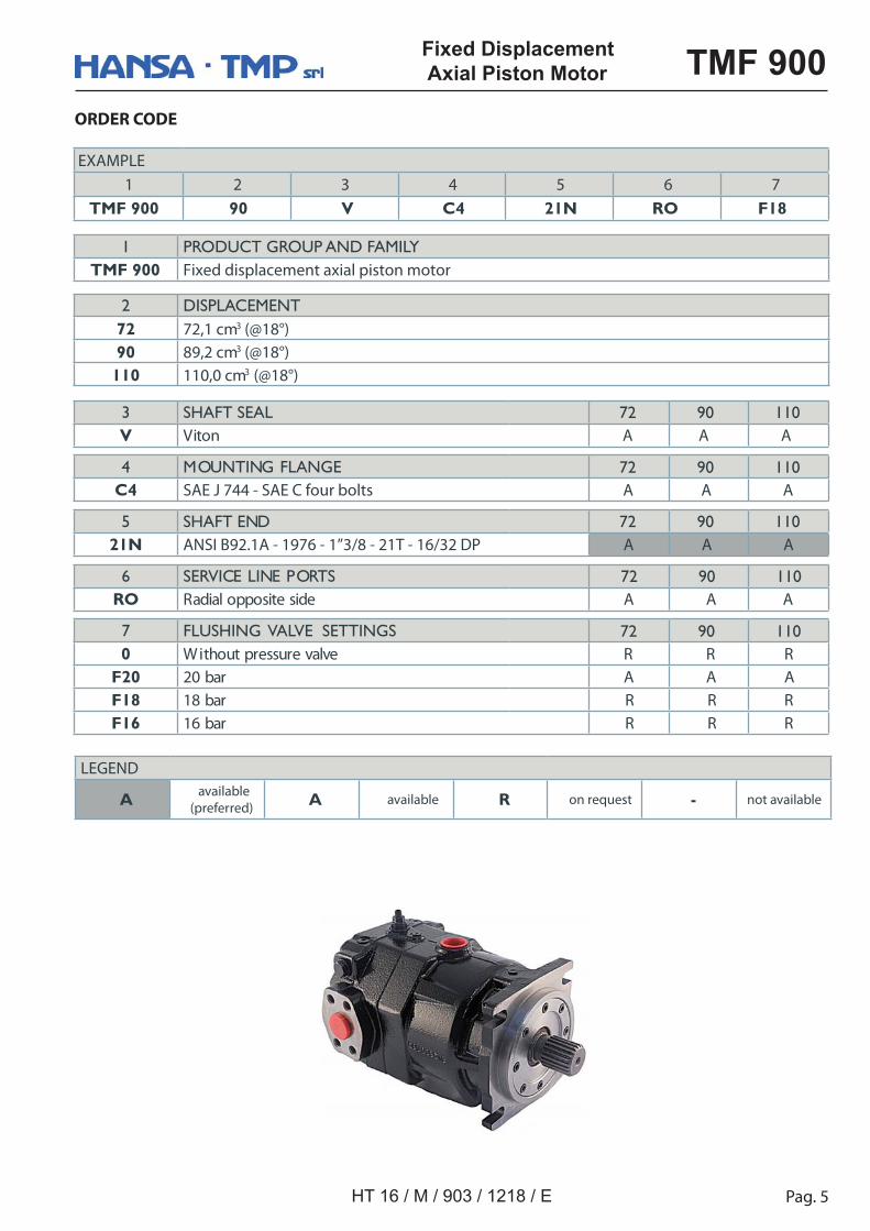
ORDER CODE
1 PRODUCT GROUP AND FAMILY TMF 900 Fixed displacement axial piston motor
Shaft End 21 NANSI B92.1A-1976 - 1"3/8 - 21 T - 16/32 DP
Ports
Detail Ports A-B SAE J 518 - 1"- Code 62
Pag. 8
Fixed Displacement Axial Piston Motor
HT 16 / M / 903 / 1218 / E
TMF 900DIRECTION of ROTATION - DIRECTION of the FLOW
Ports
Hydraulic Diagram
Flow direction through the motor
Direction of rotationR tuo A ot ni B)WC(
L tuo B ot ni A)WCC(
B portA port
CounterClockwise ClockwiseL - (CCW)
R - (CW)
T1
A T2 B
A, B High pressure ports
T1, T2 Case Drain ports
Flushing Valve
The motor is equipped with a flushing valve, integrated on the distributor of the motor that allowsto direct a flow of oil from the low pressure channel inside the motor and later, through the discharge port, to a heat exchanger. This flow is restored by the anticavitation valve onthe pump.The use of this valve allows dispose of excessive heat.
Flushing ValveFlushing Relief Valve
Pag. 9 HT 16 / M / 903 / 1218 / E
Fixed Displacement Axial Piston Motor TMF 900
INSTALLATION INSTRUCTION
Introduction
Installation Position
In the following pages are described the standards of installation of the motor. Compliance of the standards set has decisive effect on the life of the unit.The following illustration can identify the links for a correct installation. A standard requirement is that the motor must be filled with pre filtered hydraulic oil. The case must be filled with oil both in operation and during the break.The motor must be connected to the tank through the drain line. Lack of compliance with that condition can damage the unit irreparably.
Case drain port - T1 port
Case drain port - T2 port
High pressure port - A port
High pressure port - B port
The case drain line must be always connected with the highest port. The motor can be installed in the following positions respect to the level of the tank of the hydraulic fluid:
setoNnoitatneirO rotoM
gninoitisoP dradnatSknat eht rednU
Above the tank
You must provide a nonreturn valve on the case drain line to prevent the emptying of the line.
Pag. 10
Fixed Displacement Axial Piston Motor
HT 16 / M / 903 / 1218 / E
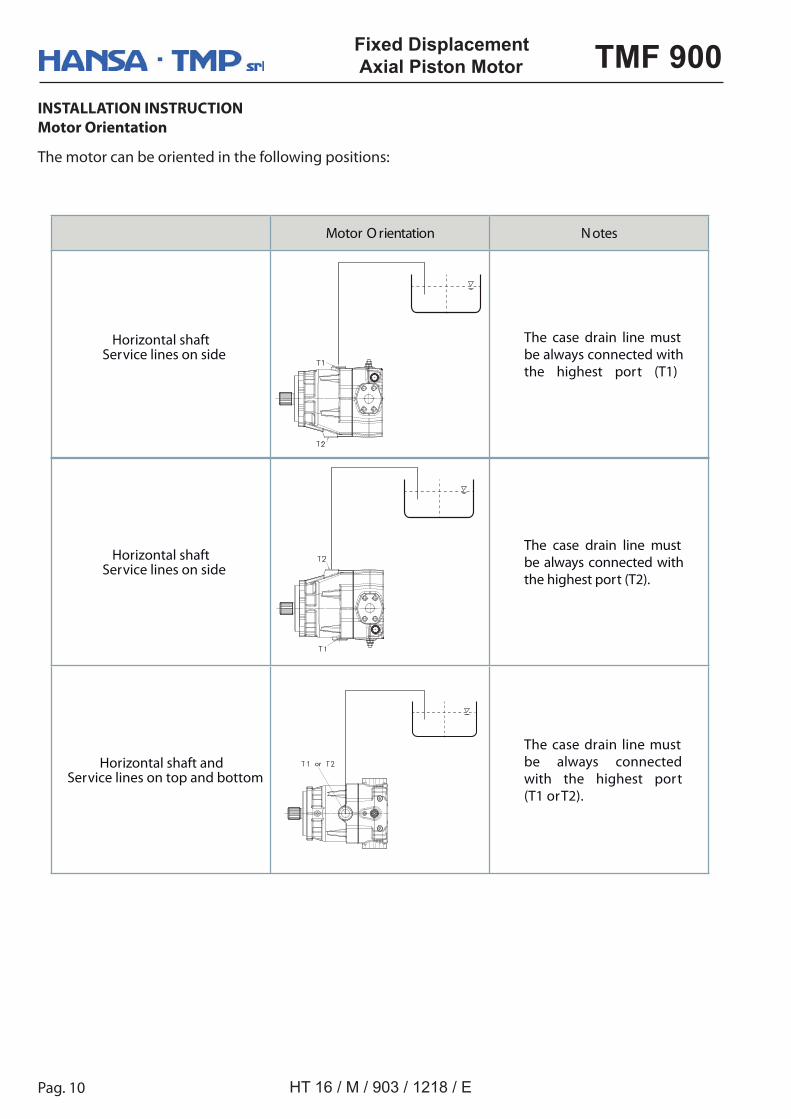
TMF 900INSTALLATION INSTRUCTION
Motor Orientation
The motor can be oriented in the following positions:
Horizontal shaftService lines on side
The case drain line must be always connected with the highest port (T2).
Horizontal shaft and Service lines on top and bottom
The case drain line must be always connected with the highest port (T1 or T2).
or
setoNnoitatneirO rotoM
Horizontal shaftService lines on side
The case drain line must be always connected with the highest port (T1)
2 www.hansatmp.com
PRODUCT GUIDE
Axial Piston Motors (Fixed Displacement) - 22-110 cc
As HANSA-TMP has a very extensive range of products and some products have a variety of applications, the information supplied may often only apply ��������������� ��
If the catalogue does not supply all the information required, please contact ����������� ��������������������������� ��������������������!��������������������������"��� "���������������������� �
Whilst every reasonable endeavour has been made to ensure accuracy, thispublication cannot be considered to represent part of any contract, whether �#������������������


![Mail van Hansa Green Tour - [Test] Travel Report …...[Test] Travel Report Hansa Green Tour Winter Edition 2018 - part 2 1 bericht Hansa Green Tour](https://static.documents.pub/doc/80x56/5eceb49492a028425752547f/mail-van-hansa-green-tour-test-travel-report-test-travel-report-hansa.jpg)


