The Quad Confinement Thruster - Preliminary Performance Characterization and Thrust Vector Control IEPC-2011-099 Presented at the 32 nd International Electric Propulsion Conference, Wiesbaden, Germany September 11–15, 2011 Aaron Knoll * , Byron Melly † , and Vaios Lappas ‡ University of Surrey, Guildford, Surrey, GU2 7XH, United Kingdom A new variety of electric thruster, the Quad Confinement Thruster, has been designed and tested during a preliminary one year development effort. This thruster utilizes an innovative magnetic cusp topology. Eight electromagnets are used to create a convex magnetic field structure with a center cusp, and four outlying cusps along the periphery. The thrust produced by the device is derived from the momentum of ions accelerated through a Hall effect static electric field. Direct thrust measurements show a specific impulse up to 700s at powers of less than 100W. This specific impulse was achieved using a propellant flow rate of 5sccm of Krypton, and corresponded to a thrust of approximately 2.1mN. One of the key motivations for this research is the ability of this thruster to actively control the direction of thrust through manipulation of the magnetic field by regulating power to the individual solenoid magnets. Preliminary experiments, which measure the profile of the plasma density at two axial stations downstream of the channel exit, appear to show a 14 degree thrust vectoring capability of the device. I. Introduction The Quad Confinement Thruster (QCT) is a new concept for plasma propulsion developed within the Electric Propulsion Group of the Surrey Space Centre. The magnetic topology employed for this device is unique amongst electric thrusters, and is illustrated schematically in Fig. 1 (as viewed along the axis of the thruster). The magnetic field contains five cusps: four cusps located at the midsections of the channel walls and a fifth cusp at the center of the channel. The layout of the magnetic field is used to weakly confine electrons within the channel and enhance the ionization efficiency of the device. The ions, by virtue of their higher mass to charge ratio, are virtually unaffected by the magnetic field and are accelerated by an axial electric field imposed between the cathode and anode of the thruster. The thrust generated by the device is derived from the momentum of ions leaving the thruster. The original motivation for this convex magnetic confinement topology can be credited to the work of Ioffe et al. 1 related to high energy discharge experiments for fusion applications. In the current work, this confinement topology is applied to an electric thruster using eight independently controlled electromagnets. The topology of the magnetic field can be manipulated by regulating the power supplied to each of the magnets. One of the key motivations behind this thruster concept is that such a change to the magnetic field not only relocates the center of thrust, but also changes the direction of ion acceleration. Therefore, this thruster provides a new capability that may prove useful to future spacecraft missions: the ability to actively vector the direction of thrust without the need for moving parts. The design of this thruster has been motivated by the success of other cusp confinement thruster concepts such as the High Efficiency Multi- * Research Officer, Surrey Space Centre, [email protected]† Student, Surrey Space Centre, [email protected]‡ Reader, Surrey Space Centre, [email protected]1 The 32 nd International Electric Propulsion Conference, Wiesbaden, Germany September 11–15, 2011
Transcript
The Quad Confinement Thruster - Preliminary
Performance Characterization and Thrust Vector
Control
IEPC-2011-099
Presented at the 32nd International Electric Propulsion Conference,Wiesbaden, Germany
September 11–15, 2011
Aaron Knoll∗ , Byron Melly† , and Vaios Lappas‡
University of Surrey, Guildford, Surrey, GU2 7XH, United Kingdom
A new variety of electric thruster, the Quad Confinement Thruster, has been designedand tested during a preliminary one year development effort. This thruster utilizes aninnovative magnetic cusp topology. Eight electromagnets are used to create a convexmagnetic field structure with a center cusp, and four outlying cusps along the periphery.The thrust produced by the device is derived from the momentum of ions acceleratedthrough a Hall effect static electric field. Direct thrust measurements show a specificimpulse up to 700s at powers of less than 100W. This specific impulse was achieved usinga propellant flow rate of 5sccm of Krypton, and corresponded to a thrust of approximately2.1mN. One of the key motivations for this research is the ability of this thruster to activelycontrol the direction of thrust through manipulation of the magnetic field by regulatingpower to the individual solenoid magnets. Preliminary experiments, which measure theprofile of the plasma density at two axial stations downstream of the channel exit, appearto show a 14 degree thrust vectoring capability of the device.
I. Introduction
The Quad Confinement Thruster (QCT) is a new concept for plasma propulsion developed within theElectric Propulsion Group of the Surrey Space Centre. The magnetic topology employed for this device isunique amongst electric thrusters, and is illustrated schematically in Fig. 1 (as viewed along the axis of thethruster). The magnetic field contains five cusps: four cusps located at the midsections of the channel wallsand a fifth cusp at the center of the channel. The layout of the magnetic field is used to weakly confineelectrons within the channel and enhance the ionization efficiency of the device. The ions, by virtue of theirhigher mass to charge ratio, are virtually unaffected by the magnetic field and are accelerated by an axialelectric field imposed between the cathode and anode of the thruster. The thrust generated by the device isderived from the momentum of ions leaving the thruster.
The original motivation for this convex magnetic confinement topology can be credited to the work ofIoffe et al.1 related to high energy discharge experiments for fusion applications. In the current work, thisconfinement topology is applied to an electric thruster using eight independently controlled electromagnets.The topology of the magnetic field can be manipulated by regulating the power supplied to each of themagnets. One of the key motivations behind this thruster concept is that such a change to the magneticfield not only relocates the center of thrust, but also changes the direction of ion acceleration. Therefore,this thruster provides a new capability that may prove useful to future spacecraft missions: the ability toactively vector the direction of thrust without the need for moving parts. The design of this thruster hasbeen motivated by the success of other cusp confinement thruster concepts such as the High Efficiency Multi-
1The 32nd International Electric Propulsion Conference, Wiesbaden, Germany
September 11–15, 2011
Figure 1. (a) Schematic layout of the QCT magnets, and (b) the resulting simulated field topology.
stage Plasma (HEMP) thruster2 and the Diverging Cusped Field (DCF) thruster3, which have been foundto exhibit relatively high levels of performance even at low powers.
A prototype of the QCT device has been designed, constructed, and tested during a one year developmenteffort. This paper presents the experimental results gathered during this project, including direct thrustmeasurements (section III) and plume diagnostics using Langmuir probes (section IV). A preliminary analysisof the thrust vectoring capabilities of this device was conducted using cross-channel plume measurements ofthe plasma density at two distances from the channel exit. These results are presented in section V.
II. Description of the QCT Laboratory Demonstrator
The QCT laboratory demonstrator is illustrated in Fig. 2, showing a solid model and cut-away view of thedesign. The acceleration channel of this device is a rectangular volume with dimensions of 30mm × 30mm ×55mm. The walls of the acceleration channel are composed of Macor ceramic, coated with a layer of BoronNitride. The anode of the thruster is constructed from high purity tungsten. This material was selectedfor its exceptional strength at high temperatures, and excellent resilience to ion sputtering. Propellant isinjected from a feed line attached to the rear of the thruster, and enters the channel around the periphery ofthe anode. The propellant selection, as in the case of the Hall Effect, HEMP, and DCF thrusters, is basedon a combination of high ionization cross section and high ion mass. Although Xenon is the natural choicefor such thrusters, Krypton propellant was selected for the preliminary characterization performed in thisstudy owing to its relative low cost versus high performance. The QCT device was characterized using flowrates of 5, 10, and 15 sccm of Krypton propellant during these experiments.
The magnetic circuit is composed of eight electromagnets mounted on an aluminum base plate. The fullywound electromagnets, mounted on the base plate, are shown in Fig. 3. The electromagnetic circuit wasused to produce a peak field strength up to 250 Gauss within the channel of the thruster. The power versuspeak magnetic field strength for the electromagnetic setup, characterized with the use of a Sypris model5170 portable Gauss meter, is provided in Fig. 4.
Various scenarios were investigated to steer the magnetic field topology by manipulating the powersupplied to the eight solenoid magnets (four solenoid magnet pairs). The impact of this manipulation on themagnetic field topology was assessed using a simple 2-dimensional simulation. The first scenario that wasinvestigated was to reduce the power of a single solenoid magnet pair, while holding the remaining magnetsconstant. A schematic view of this scenario, and the results of the magnetic field analysis, are shown inFig. 5. This steering technique, as illustrated by the results of the 2-dimensional analysis, was found to
2The 32nd International Electric Propulsion Conference, Wiesbaden, Germany
September 11–15, 2011
Figure 2. (a) Solid model of the laboratory demonstrator, and (b) cut-away view of the laboratory demon-strator.
Figure 3. QCT electromagnets mounted on an aluminum base plate.
Figure 4. Peak magnetic field strength versus power for the electromagnetic setup.
3The 32nd International Electric Propulsion Conference, Wiesbaden, Germany
September 11–15, 2011
be relatively ineffective at altering the magnetic field topology. The second scenario that was investigatedwas to simultaneously reduce the power of two solenoid magnet pairs, while holding the remaining magnetsconstant. This revised steering scenario proved to have a major impact on the field topology. A schematicview of this scenario, and the results of the magnetic field analysis, are shown in Fig. 6. The magnetic cusp,originally located at the center of the channel, could be relocated over the entire channel span by adjustingthe relative power of the two solenoid pairs simultaneously. For the experiments described in this paper,three magnetic steering scenarios were investigated: (i) the symmetric case with the cusp located in thecenter of the channel, (ii) the cusp fully relocated to the left hand side of the channel, and (iii) the cuspfully relocated to the right hand side of the channel. These conditions will be subsequently referred to asthe symmetric, far left, and far right steering scenarios respectively.
Figure 5. Alteration of the magnetic field by adjusting the relative power of one solenoid magnet pair.
Figure 6. Alteration of the magnetic field by simultaneously adjusting the relative power of two solenoidmagnet pairs.
A hollow cathode is utilized by the QCT device to sustain the discharge and neutralize the outgoingion beam. Two types of hollow cathodes were used during this project. The first was a custom designedlow power cathode4 constructed in-house at the Surrey Space Centre. The second was a commercial hollowcathode: Heatwave model HWPES-250. In both cases the cathode was operated with a flow rate of 5sccmKrypton gas at a discharge power of approximately 25W.
Pictures of the experimental setup and the QCT device in operation are provided in Fig. 7. The basiccurrent versus voltage characteristics of this thruster are plotted in Fig. 8. These results are reported fora single flow rate of 10sccm Krypton, but are also representative of the behavior at the 5sccm and 15sccmflow conditions. We can observe from this plot that the magnetic field strength plays an important role inregulating the discharge current at low voltages, but does not significantly impact the saturation current ofthe device at higher voltage levels.
4The 32nd International Electric Propulsion Conference, Wiesbaden, Germany
September 11–15, 2011
Figure 7. Picture of the experimental setup (a), and QCT device in operation (b).
Figure 8. Current versus voltage characteristics of the QCT discharge at a flow rate of 10sccm Krypton.
5The 32nd International Electric Propulsion Conference, Wiesbaden, Germany
September 11–15, 2011
Further insight into the influence of the magnetic field on the operating conditions of the thruster wasgained by altering the magnetic field while maintaining a constant current to the thruster. This test wasperformed for a 2 Amp discharge at a flow rate of 10sccm. The magnetic field was adjusted from 0 to250 Gauss at 25 Gauss increments. The results of this experiment are shown in Fig. 9. We can see thatincreasing the magnetic field acts to increase the discharge voltage in an almost linear fashion. In this case,the voltage increased from 56V without a magnetic field to 67V with a 250 Gauss field.
Figure 9. Voltage versus magnetic field at a 10sccm Krypton flow rate and a 2A discharge current.
III. Thrust Measurements
A custom built high sensitivity thrust stand has been developed internally within the Surrey SpaceCentre. This device achieves a measurement accuracy of approximately 0.1mN. This thrust stand is aninverted pendulum device, which displaces slightly under an applied force. The amount of displacementversus applied force is determined by the rigidity of the flexors used in the design. The displacement ismeasured with a MicroEpsilon laser optical displacement sensor, model number ILD 1700-50. The thruststand has a built-in stepper motor and pulley apparatus that allows the stand to be calibrated activelyduring experimental trials. This apparatus works by suspending a weight with a precisely known mass froma pulley that transfers this force directly to the thrust stand. A schematic of the device is shown in Fig. 10.Further details of the thrust stand can be found in the reference by Pottinger et al.4.
Figure 10. Schematic drawing of the Surrey Space Centre thrust stand.
6The 32nd International Electric Propulsion Conference, Wiesbaden, Germany
September 11–15, 2011
The following procedure was used for each experimental trial to determine the thrust force producedby the device. Each experiment was conducted over a 80s duration. Over this period the thruster was onfor the first 40s, and turned off for the next 40s. The net thrust produced by the device was establishedby averaging the laser displacement measurement over the period when the thrust was on, and comparingto the average displacement while the thruster was off. This experimental technique was used for initialinvestigation because it is fast, but admittedly not very accurate. This can be seen by the relatively widespread of the thrust data points to follow.
Experiments were conducted using a propellant flow rate of 5, 10, and 15sccm of Krypton. The thrust andspecific impulse versus power for each flow rate are plotted in Fig. 11 through 13 respectively. The dischargepower was varied incrementally between 20W and 60W, and a constant peak magnetic field strength of 150Gauss was used throughout. Despite the relatively large spread of this data, we can observe from these plots aroughly linear relationship between the discharge power and thrust. We can see that the QCT device clearlyfavors lower flow rates for these low power operating conditions. The highest specific impulse during theseexperiments was roughly 700s at 50W discharge power, which was obtained at the 5sccm flow conditions.This corresponds to a measured thrust of approximately 2.1mN.
Figure 11. Thrust and specific impulse versus discharge power for a 5sccm Krypton propellant flow rate anda magnetic field strength of 150 Gauss.
Figure 12. Thrust and specific impulse versus discharge power for a 10sccm Krypton propellant flow rate anda magnetic field strength of 150 Gauss.
7The 32nd International Electric Propulsion Conference, Wiesbaden, Germany
September 11–15, 2011
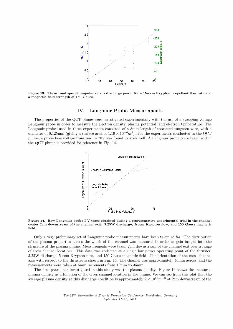
Figure 13. Thrust and specific impulse versus discharge power for a 15sccm Krypton propellant flow rate anda magnetic field strength of 150 Gauss.
IV. Langmuir Probe Measurements
The properties of the QCT plume were investigated experimentally with the use of a sweeping voltageLangmuir probe in order to measure the electron density, plasma potential, and electron temperature. TheLangmuir probes used in these experiments consisted of a 3mm length of thoriated tungsten wire, with adiameter of 0.125mm (giving a surface area of 1.19 × 10⁻⁶m2). For the experiments conducted in the QCTplume, a probe bias voltage from zero to 70V was found to work well. A Langmuir probe trace taken withinthe QCT plume is provided for reference in Fig. 14.
Figure 14. Raw Langmuir probe I-V trace obtained during a representative experimental trial in the channelcenter 2cm downstream of the channel exit: 3.25W discharge, 5sccm Krypton flow, and 150 Gauss magneticfield.
Only a very preliminary set of Langmuir probe measurements have been taken so far. The distributionof the plasma properties across the width of the channel was measured in order to gain insight into thestructure of the plasma plume. Measurements were taken 2cm downstream of the channel exit over a rangeof cross channel locations. This data was collected at a single low power operating point of the thruster:3.25W discharge, 5sccm Krypton flow, and 150 Gauss magnetic field. The orientation of the cross channelaxis with respect to the thruster is shown in Fig. 15. The channel was approximately 40mm across, and themeasurements were taken at 5mm increments from 10mm to 35mm.
The first parameter investigated in this study was the plasma density. Figure 16 shows the measuredplasma density as a function of the cross channel location in the plume. We can see from this plot that theaverage plasma density at this discharge condition is approximately 2× 10¹⁵m−3 at 2cm downstream of the
8The 32nd International Electric Propulsion Conference, Wiesbaden, Germany
September 11–15, 2011
Figure 15. Schematic representation of the cross channel axis used for the Langmuir probe experiments.
channel exit. The actual value of the plasma density at this location is of little concern, because the plasmadensity will vary significantly with the applied discharge power. However, this data gives us an insight intothe structure of the plasma density across the channel. We can see from this plot that the variation of thedensity resembles a Gaussian curve with a peak amplitude located at the central axis of the thruster.
Figure 16. Electron number density as a function of the cross channel location 2cm downstream of the channelexit: 3.25W discharge, 5sccm Krypton flow, 150 Gauss magnetic field.
The second parameter that was measured in the plasma plume was the electron temperature. Figure17 shows the electron temperature as a function of the cross channel location. Unlike the behavior of theplasma density, the electron temperature is nearly constant across the channel at a value of 5.3eV. We cansee from this plot that the electron temperature increases slightly at the far edge of the channel towards theright hand side of the figure, but is predominantly flat elsewhere.
The final parameter that was investigated with the use of the Langmuir probes was the plasma potential.The distribution of the plasma potential across the channel is of great experimental interest, because itgives us some insight into the ability of the QCT to actively vector the direction of thrust. To clarify theconnection between the plasma potential distribution and the thrust vectoring capability, we consider thefollowing thought experiment. If the plasma potential is perfectly uniform across the channel cross sectionat each axial location, then there cannot exist an electric field that acts in any direction except along theaxis of the thruster. However, if the plasma potential does vary as a function of location across the channel,then there must exist components of the electric field that act in a direction perpendicular to the channelaxis. It then becomes possible that by altering the topology of the plasma discharge (through manipulationof the magnetic cusp location) we introduce cross-channel electric fields that can accelerate the ions at anangle with respect to the channel axis.
The distribution of the plasma potential as a function of the cross channel location is shown in Fig. 18.
9The 32nd International Electric Propulsion Conference, Wiesbaden, Germany
September 11–15, 2011
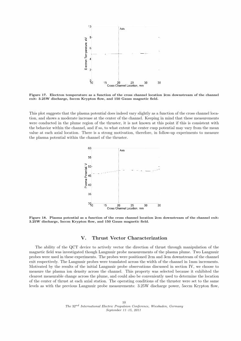
Figure 17. Electron temperature as a function of the cross channel location 2cm downstream of the channelexit: 3.25W discharge, 5sccm Krypton flow, and 150 Gauss magnetic field.
This plot suggests that the plasma potential does indeed vary slightly as a function of the cross channel loca-tion, and shows a moderate increase at the center of the channel. Keeping in mind that these measurementswere conducted in the plume region of the thruster, it is not known at this point if this is consistent withthe behavior within the channel, and if so, to what extent the center cusp potential may vary from the meanvalue at each axial location. There is a strong motivation, therefore, in follow-up experiments to measurethe plasma potential within the channel of the thruster.
Figure 18. Plasma potential as a function of the cross channel location 2cm downstream of the channel exit:3.25W discharge, 5sccm Krypton flow, and 150 Gauss magnetic field.
V. Thrust Vector Characterization
The ability of the QCT device to actively vector the direction of thrust through manipulation of themagnetic field was investigated though Langmuir probe measurements of the plasma plume. Two Langmuirprobes were used in these experiments. The probes were positioned 2cm and 3cm downstream of the channelexit respectively. The Langmuir probes were translated across the width of the channel in 1mm increments.Motivated by the results of the initial Langmuir probe observations discussed in section IV, we choose tomeasure the plasma ion density across the channel. This property was selected because it exhibited theclearest measurable change across the plume, and could also be conveniently used to determine the locationof the center of thrust at each axial station. The operating conditions of the thruster were set to the samelevels as with the previous Langmuir probe measurements: 3.25W discharge power, 5sccm Krypton flow,
10The 32nd International Electric Propulsion Conference, Wiesbaden, Germany
September 11–15, 2011
and 150 Gauss magnetic field.An initial data set was recorded for the symmetric magnetic field condition, and was used as a reference
for subsequent thrust vectoring experiments. These results are provided in Fig. 19. The data was fit toa Gaussian curve at each axial station using least squares analysis. A downward facing arrow shows thecalculated direction of the thrust center between the two downstream locations, which was set to a referencezero condition for the symmetric magnetic field. Unlike the analysis conducted in section IV, the actualvalue of the ion density is not needed for this experiment. Therefore, these plots show the unprocessed ioncurrent taken with the Langmuir probe when operating in the ion saturation regime (probe biased to thechamber ground potential). This was an experimental convenience, because seeping voltage measurementswere not needed for these trials.
Figure 19. Ion density versus cross channel location for the symmetric magnetic field condition measured attwo downstream locations: 2cm (o) and 3cm (*).
Figure 20 and 21 show the results gathered for the far left and far right hand steering conditions respec-tively (as defined previously in section II). Although preliminary, these results appear to provide evidence ofan angular steering of the ion beam. The angular offset of the beam from the thruster axis was symmetric,giving +7 degrees and -7 degrees for the left and right hand case respectively.
Figure 20. Ion density versus cross channel location for the far left steering condition measured at twodownstream locations: 2cm (o) and 3cm (*).
One of the weaknesses of this experimental technique was that the inclination of the beam was onlymeasured along a single axis. If the beam vectoring is in the same sense as the relocation of the centralmagnetic cusp, then the hypothetical axis of the beam steering should be inclined 45 degrees to the axisof these measurements. Therefore, there is a possibility that the actual thrust vectoring capability wasunderestimated and should be closer to 20 degrees (+/- 10 degrees in each direction).
11The 32nd International Electric Propulsion Conference, Wiesbaden, Germany
September 11–15, 2011
Figure 21. Ion density versus cross channel location for the far right steering condition measured at twodownstream locations: 2cm (o) and 3cm (*).
Motivated by the need to understand the 3-dimensional behavior of the QCT plume, a custom designed3-axis motion stage5 has been designed and constructed within the Surrey Space Centre. This motionstage, shown in Fig. 22, will be used as a Langmuir probe holder to conduct a 3-dimensional survey ofthe QCT plume in terms of electron density, temperature, and potential. Both the symmetric and steeredmagnetic field conditions will be investigated. These experiments will also explore a wide range of magneticfield settings and operating conditions, with the aim of understanding and optimizing the thrust vectoringcapabilities of the device.
Figure 22. Solid model of the Surrey Space Centre 3-axis probe holder.
VI. Conclusion
The Quad Confinement Thruster has demonstrated the use of an innovative magnetic cusp confinementtopology for thrust generation during this one year development effort. Although experimental results
12The 32nd International Electric Propulsion Conference, Wiesbaden, Germany
September 11–15, 2011
are very preliminary at this stage, the device shows early promise as a new variety of electric propulsiontechnology.
The key advantage of this concept is the ability to actively control the direction of thrust throughmanipulation of the magnetic field topology. Preliminary experiments appear to show a thrust vectoringcapability of 14 degrees. However, these experiments were only recorded along a single measurement axis,and at a single operating point of the thruster. Follow-up experiments are needed to properly resolve the3-dimensional structure of the plume under a variety of discharge conditions in order to accurately determinethe thrust vectoring capabilities of this device.
Acknowledgments
This research has been funded through the University of Surrey’s strategic partnership with EADSAstrium. The authors would like to thank Matthew Perren for his support during this project. Also, theauthors would like to thank the University of Surrey for sponsoring the costs associated with filing the QCTpatent (application number GB1009078.5 filed June 1st, 2010).
References
1M. S. Ioffe, B. I. Kanaev, V. P. Pastukhov, V. V. Piterskii and E. E. Yushmanov, “Plasma heating in amagnetic cusp confinement system without injection,” JETP Lett., October 1981, Vol 34, No 11.
2Kornfeld, G., Koch, N., and Harmann, H. P., “New Performance and Reliability Results of the THALESHEMP Thruster,” 4th International Spacecraft Propulsion Conference (ESA SP-555), ESA PublicationsDivision, ESTEC, Noordwijk, The Netherlands, 2-9 June, 2004, Published on CDROM., p.39.1.
3Courtney, D., “Development and Characterization of a Diverging Cusped-Field Thruster and a Lan-thanum Hexaboride Hollow Cathode,” Master of Science Dissertation, Massachusetts Institute of Technology,Boston, Massachusetts, 2008.
4S. J. Pottinger, D. Lamprou, A. K. Knoll, and V. J. Lappas, “Impact of Plasma Noise on a DirectThrust Measurement System,” Review of Scientific Instruments (under review).
5Shafiq, U., “Design of a three axis translation mechanism using stepper motors,” Master of ScienceDissertation, University of Surrey, Guildford, Surrey, United Kingdom, 2011.
13The 32nd International Electric Propulsion Conference, Wiesbaden, Germany