The Range Linea 24 ● Linea 28 Installation & Servicing Instructions British Gas Service Listed G.C. No. 47 094 27 (Linea 24) G.C. No. 47 094 28 (Linea 28) G.C. No. 47 094 29 (Linea Plus) THESE INSTRUCTIONS TO BE RETAINED BY USER
Transcript
The RangeLinea 24 Linea 28
Installation& ServicingInstructions
British Gas Service ListedG.C. No. 47 094 27 (Linea 24)G.C. No. 47 094 28 (Linea 28)
G.C. No. 47 094 29 (Linea Plus)
THESE INSTRUCTIONSTO BE RETAINEDBY USER
Linea 24 & 28
CONTENTSSection Subject Page no
Section 1 Introduction 1General Layout 1
Section 2 Design Principles & OperatingPrinciples 2Schematic Diagram 2Central Heating Mode 2Domestic Hot Water Mode 2Safety Devices 2Frost Thermosat 2
Section 4 General Requirements 5Related Documents 5Location of Appliance 5Gas Supply 5Flue System 5Air Supply 6Water Circulation (C/H) 6Pipework 6By-Pass 6System Design 6Filling Point 8Electrical Supply 8Showers 8
Section 5 Installation 9Delivery 9Unpacking 9Preparing For Mounting 9Mounting The Appliance 10Fitting The Flue (Horizontal) 10Fitting The Flue (Vertical) 11Fitting The Flue (Twin) 12Connecting Gas & Water Supplies 15Electrical connections 15
Section 6 Commissioning 17Gas Installation 17Initial Flushing of Pipework 17Initial Filling of System 17System Design Pressure 17Checking Electrical supply 17Lighting The Boiler 17Checking Burner Pressures 18Range Rating C/H 19Checking The Flue System 19Checking The Heating Thermistor 19Regulating The C/H System 19Final Flushing The C/H System 19Filling & Testing H/W System 19Final Checks For Operation 20
Section 1 0 Appendix 44Internal Time Clock Installation 44External Time Clock Installation 46S & Y Plan Installations 47Exploded Diagrams 48-52Abling & Disabling Controls 53Functional Flow Diagram 54Illustrated Wiring Diagram 55Preliminary Electrical System Checks 56LPG Instructions 57-58
Linea 24 & 28 1
These appliances are designed for use with asealed heating system only and are not in-tended for use on an open vented system.
The provision of stored domestic hot water ispossible by the addition of an indirect cylinderwith 'S' or 'Y' plan controls.
An automatic range-rating facility is incorpo-rated in the boiler for the central heating sys-tem in conjunction with the electronic burnermodulation. The domestic hot water (dhw)service utilises a motorised control combinedwith a 3 port diverter valve to give hot waterpriority which also benefits from a preheatfunction.
The Vokèra Linea 24 & 28 are combinedcentral heating and domestic hot water appli-ances. By design they incorporate full se-quence electronic ignition, circulating pump,expansion vessel, safety valve, temperaturegauge, pressure gauge and 3 port divertervalve.
They are produced as room sealed appli-ances suitable for wall mounting applicationsonly. They are provided with a fan poweredflue outlet with an annular co-axial combustionair intake which can be rotated through 360degrees. A vertical & twin flue option is avail-able They are also suitable for S.E. duct instal-lation.
SECTION 1 INTRODUCTION
Fig.1 General Layout
1 Flue Outlet2 Air Intake & Restrictor Ring3 Pressure Differential Switch4 Silicone Pressure Tubes5 Expansion Vessel6 Main Heat Exchanger7 Flow NTC8 Electrode9 Gas Valve & Ignition Control10 Modulator Coil11 Domestic Heat Exchanger12 Domestic Hot Water Flow Switch13 Status LED14 Temperature Indicator15 Central Heating Temperature Control16 Combustion Switch17 Timeclock Aperture (optional)18 Pressure Gauge19 Mode Selector Switch20 Hot Water Temperature Control21 Safety Valve22 Pressure switch23 Diverter Valve Motor24 Pump25 Automatic Air Release Valve26 Main Burner27 Combustion Chamber28 Fan Assembly29 Air Chamber (with front removed)30 Flue Gas Analysis Test Point
2019
18
13
17
161514
2 Linea 24 & 28
SECTION 2 DESIGN PRINCIPLES AND OPERATING SEQUENCE
2.1 Fig.1 illustrates the general layout of compo-nents. Fig.2 illustrates the operating principlesdescribed below.
2.2 Central Heating Mode
2.2.1 When the various switches and controls im-pose a demand for heat, the pump is started.If the primary pressure is sufficient, the elec-tronic circuitry is energised. The fan is started,the gas valve is energised at an intermediaterate and the electronic ignition goes throughan ignition attempt.
2.2.2 The burner ignition is checked by the elec-tronic circuitry to ensure correct ignition of theburner; once successful the gas will flow at75% of maximum heat input for a period ofapproximately 15 minutes and then go tomaximum heat input to maximise heating per-formance, unless the boiler nears optimumtemperature where it will modulate down tosuit system load.
2.2.3 As water temperature increases this is sensedby the temperature sensor on the primary heatexchanger which modulates the burner tomatch the heat output to the heat requirementof the system.
2.2.4 Depending on the load, either a) The watertemperature will continue to rise and the burnerwill continue to modulate down; The burnerwill switch off at maximum temperature, or b)the water temperature will fall; the burnerwill return to a higher output to match demand.
2.3 Domestic Hot Water Mode
2.3.1 The appliances incorporate a hot water preheatfacility. The appliance will therefore igniteperiodically to maintain heat within the appli-ance.
2.3.2 The appliance will operate in domestic hotwater mode whenever the mode selector switchis on regardless of mode selector switchposition and any demand for central heating.
2.3.3 The diverter valve will automatically energiseinto the hot water position after central heatingdemand, or will stay in the hot water positionafter hot water demand. Opening a draw offtap will energise the pump and fan sendingprimary water to the domestic hot water heatexchanger.
2.3.4 Temperature control is transferred to the do-mestic hot water thermostat (potentiometer)which modulates the burner output betweenhigh and low flame to maintain an averageheat input to suit the dhw output required.
2.3.5 An overrun is incorporated in the boiler in bothc/h & dhw modes. The fan overruns until theboiler water cools to approximately 80°C(176°F).
2.4 Safety Devices
2.4.1 In both central heating and hot water modessafe operating is ensured by:
A. Differential pressure unit in the primarycircuit which prevents burner operation if waterpressure is too low.
B. An electronic device that checks the pri-mary pressure unit for activation. Failure re-sults in deactivation of the pump, after ap-proximately 10 minutes of operation.
C. A safety thermostat, which interrupts thecontrol circuit shutting off the gas valve. At thesame time the fan will still operate.
D. A Pressure differential switch in the fluesystem to check the fan's operation beforeallowing ignition.
2.4.2 A safety valve is provided to relieve excesspressure from the primary circuit.
2.4.3 Frost Thermostat
The appliance has a built in frost protectioncircuit. Should the boiler temperature sensed atthe primary thermistor fall below 5°C, the boilerwill operate in central heating mode and continueto operate until the primary thermistor reachesapproximately 40°C.
KEY:A Central Heating Return.B Central Heating Flow.C Hot Water Outlet.D Cold Water Inlet.
NOTE: pressure switch. Senses water pressure in theprimary circuit and operates the pressure switch(22)
Fig. 2
Air Intake
Flue Outlet
A B C D
12NOTE
22
5
25
24
36
26
9
11
23
Linea 24 & 28 3
SECTION 3 TECHNICAL DATA
3.1 Units Dimensions and values are given in thepreferred Sl Units with Imperial units in brack-ets where applicable.
3.2 Dimensions and Contents
Water content: 3 litres (.66 gals)for further dimensions see figs 12 - 16
3.3 Connection sizesHeating flow and return: Nut and olive for22mm o.d.Cold water inlet: Nut and olive for 15mm o.d.Hot water outlet: Nut and tail for 15mm o.d.Gas Service: Nut and tail for 15mm o.d.Safety valve outlet: 15mm comp.or capillary
Flue outlet/Air inlet: nom dia 60/100mm spe-cially supplied with boiler (concentric).Flue outlet/Air inlet: nom dia 80/80mm spe-cially supplied with boiler (twin).
3.4 Installation Requirements
3.4.1 Clearances (Horizontal or Vertical Flue)Minimum - above casing 225mm (9in) Mini-mum - below casing 200mm (8in) Minimum- In front 600mm (24in)Minimum - At sides 12mm (˚in) from casing
3.4.2 Maximum heating system contents approx.76.4 litres (16.8 gals). Acceptance capacity ofexpansion vessel 8 litres (1.8 gals).
3.4.3 Means of filling sealed system: To accord withBS and/or local Water Authority requirements.
3.4.4 Using extension tubes the flue may be ex-tended to the following lengths.
Concentric
Twin (+ concentric terminal)
The reduction in flue length for each bendused is listed opposite.
Twin FlueReduction in flue lengthfor each bendBend
90°45°
1000mm
1000mm
4 Linea 24 & 28
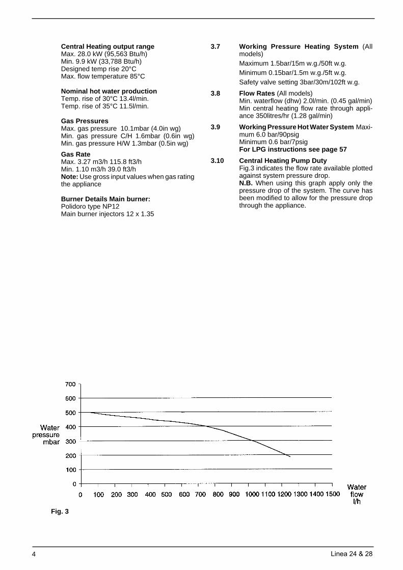
Central Heating output rangeMax. 28.0 kW (95,563 Btu/h)Min. 9.9 kW (33,788 Btu/h)Designed temp rise 20°CMax. flow temperature 85°C
Nominal hot water productionTemp. rise of 30°C 13.4l/min.Temp. rise of 35°C 11.5l/min.
Gas PressuresMax. gas pressure 10.1mbar (4.0in wg)Min. gas pressure C/H 1.6mbar (0.6in wg)Min. gas pressure H/W 1.3mbar (0.5in wg)
Gas RateMax. 3.27 m3/h 115.8 ft3/hMin. 1.10 m3/h 39.0 ft3/hNote: Use gross input values when gas ratingthe appliance
Burner Details Main burner:Polidoro type NP12Main burner injectors 12 x 1.35
3.7 Working Pressure Heating System (Allmodels)Maximum 1.5bar/15m w.g./50ft w.g.Minimum 0.15bar/1.5m w.g./5ft w.g.Safety valve setting 3bar/30m/102ft w.g.
3.8 Flow Rates (All models)Min. waterflow (dhw) 2.0l/min. (0.45 gal/min)Min central heating flow rate through appli-ance 350litres/hr (1.28 gal/min)
3.9 Working Pressure Hot Water System Maxi-mum 6.0 bar/90psigMinimum 0.6 bar/7psigFor LPG instructions see page 57
3.10 Central Heating Pump DutyFig.3 indicates the flow rate available plottedagainst system pressure drop.N.B. When using this graph apply only thepressure drop of the system. The curve hasbeen modified to allow for the pressure dropthrough the appliance.
Fig. 3
Linea 24 & 28 5
SECTION 4 GENERAL REQUIREMENTS
4.0 General Requirements
This appliance must be installed by a compe-tent person in accordance with the Gas Safety(Installation & Use) Regulations 1998.
4.1 Related Documents
The installation of this boiler must be in ac-cordance with the relevant requirements ofthe Gas Safety (Installation & Use) Regula-tions 1998 the Local Building Regulations, thecurrent l.E.E. Wiring Regulations, the by-lawsof the local water undertaking, and in Scot-land, in accordance with the Building Stand-ards (Scotland) Regulation. In Ireland the lo-cal building regulations (IE).
It should be in accordance also with any rel-evant requirements of the local authority andthe relevant recommendations of the follow-ing British Standard Codes of Practice:
4.2 Location of Appliance
The combination boiler may be installed in anyroom or internal space, although particularattention is drawn to the requirements of thecurrent l.E.E. Wiring Regulations, and in Scot-land, the electrical provisions of the BuildingRegulations applicable in Scotland, with re-spect to the installation of the combinationboiler in a room or internal space containing abath or shower.
Where a room-sealed appliance is installed ina room containing a bath or shower, anyelectrical switch or appliance control, utilisingmains electricity, should be located in such aposition that it cannot be touched by a personusing the bath or shower.
The location chosen for the boiler must permitthe provision of a satisfactory flue and termi-nation. The location must also permit an ad-equate air supply for combustion purposesand an adequate space for servicing and aircirculation around the boiler.
Where the installation of the boiler will be in anunusual location special procedures may benecessary and BS 6798:1987 gives detailedguidance on this aspect.
Pipework from the meter to the boiler must beof adequate size. Pipes of a smaller size thanthe boiler inlet connection should not be used.
The complete installation must be tested forsoundness as described in the above code.
N.B. If the gas supply for the boiler servesother appliances ensure that an adequatesupply is available both to the boiler and theother appliance when they are in use at thesame time.
4.4 Flue System
The terminal should be located where disper-sal of combustion products is not impeded andwith due regard for the damage or discolora-tion that might occur to building products in thevicinity (see fig 4).
The terminal must not be located in a placewhere it is likely to cause a nuisance.
In cold and/or humid weather water vapourmay condense on leaving the flue terminal.The effect of such ‘steaming’ must be consid-ered.
A compartment used to enclose the boilermust be designed and constructed specifi-cally for this purpose. An existing cupboard orcompartment may be used provided that it ismodified for this purpose.
Details of essential features of cupboard/ com-partment design including airing cupboard in-stallations are given in BS 6798:1987. Thisappliance is not suitable for external installa-tion.
4.3 Gas Supply
A gas meter is connected to the service pipeby the gas supplier.
An existing meter should be checked, prefer-ably by the gas supplier, to ensure that themeter is adequate to deal with the rate of gassupply required for all appliances it serves.
Installation pipes should be fitted in accord-ance with BS 6891:1988.
BS 6891 1988 Low pressure installation pipesBS 6798 1987 Boilers of rated input not exceeding 60kW.BS 5449 Part 1 1990 Forced circulation hot water systemsBS 5546 1990 Installation of gas hot water supplies
for domestic purposes (2nd family gases).BS 5440 Part 1 1990 Flues.BS 5440 Part 2 1989 Flues & Ventilation.BS 7074 Part 1 1989 Application, selection & installation of expansion
vessels & ancillary equipment for sealed watersystems.
6 Linea 24 & 28
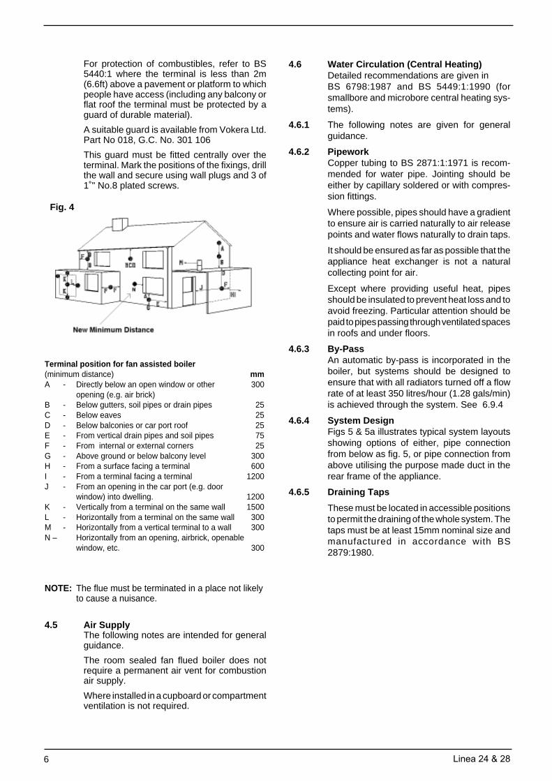
For protection of combustibles, refer to BS5440:1 where the terminal is less than 2m(6.6ft) above a pavement or platform to whichpeople have access (including any balcony orflat roof the terminal must be protected by aguard of durable material).
A suitable guard is available from Vokera Ltd.Part No 018, G.C. No. 301 106
This guard must be fitted centrally over theterminal. Mark the positions of the fixings, drillthe wall and secure using wall plugs and 3 of1˚" No.8 plated screws.
4.6 Water Circulation (Central Heating)Detailed recommendations are given inBS 6798:1987 and BS 5449:1:1990 (forsmallbore and microbore central heating sys-tems).
4.6.1 The following notes are given for generalguidance.
4.6.2 PipeworkCopper tubing to BS 2871:1:1971 is recom-mended for water pipe. Jointing should beeither by capillary soldered or with compres-sion fittings.
Where possible, pipes should have a gradientto ensure air is carried naturally to air releasepoints and water flows naturally to drain taps.
It should be ensured as far as possible that theappliance heat exchanger is not a naturalcollecting point for air.
Except where providing useful heat, pipesshould be insulated to prevent heat loss and toavoid freezing. Particular attention should bepaid to pipes passing through ventilated spacesin roofs and under floors.
4.6.3 By-PassAn automatic by-pass is incorporated in theboiler, but systems should be designed toensure that with all radiators turned off a flowrate of at least 350 litres/hour (1.28 gals/min)is achieved through the system. See 6.9.4
4.6.4 System DesignFigs 5 & 5a illustrates typical system layoutsshowing options of either, pipe connectionfrom below as fig. 5, or pipe connection fromabove utilising the purpose made duct in therear frame of the appliance.
4.6.5 Draining Taps
These must be located in accessible positionsto permit the draining of the whole system. Thetaps must be at least 15mm nominal size andmanufactured in accordance with BS2879:1980.
4.5 Air SupplyThe following notes are intended for generalguidance.
The room sealed fan flued boiler does notrequire a permanent air vent for combustionair supply.
Where installed in a cupboard or compartmentventilation is not required.
Terminal position for fan assisted boiler(minimum distance) mmA - Directly below an open window or other 300
opening (e.g. air brick)B - Below gutters, soil pipes or drain pipes 25C - Below eaves 25D - Below balconies or car port roof 25E - From vertical drain pipes and soil pipes 75F - From internal or external corners 25G - Above ground or below balcony level 300H - From a surface facing a terminal 600I - From a terminal facing a terminal 1200J - From an opening in the car port (e.g. door
window) into dwelling. 1200K - Vertically from a terminal on the same wall 1500L - Horizontally from a terminal on the same wall 300M - Horizontally from a vertical terminal to a wall 300N – Horizontally from an opening, airbrick, openable
window, etc. 300
NOTE: The flue must be terminated in a place not likelyto cause a nuisance.
Fig. 4
Linea 24 & 28 7
N.B. Vokèra Ltd recommend a 2-pipe system. Single pipe systems are more liable to be troublesome unlesscarefullly designed and installed.
Fig. 5a
Fig. 5
8 Linea 24 & 28
4.6.6 Air Release PointsThese must be fitted at all high points whereair will naturally collect, and must be sited tofacilitate complete filling of the system.
4.6.7 The appliance has an integral sealed expan-sion vessel to accommodate the increase ofwater volume when the system is heated. Itcan accept up to 8 litres (1.8gals) of expansionwater. If the appliance is connected to a sys-tem with an unusually high water content.Calculate the total expansion and add addi-tional sealed expansion capacity as appro-priate.
In general, modern systems will present noproblem.
4.6.8 Filling PointA method for filling the system and replacingwater lost during servicing is provided on theappliance.
This method complies with the Water Supply(Water Fittings) Regulations 1999.
4.7 Electrical SupplyThe appliance is supplied for operation on230V ~ 50Hz electricity supply. It should beprotected with a 3-amp fuse.
THIS APPLIANCE MUST BE EARTHED.
The method of connection to the mains elec-tricity must allow complete isolation from thesupply.
The preferred method is by using a fuseddouble pole switch with a contact separationof at least 3mm.
The switch must supply ONLY the applianceand immediate electrical control circuits (e.g.programmer / room thermostat)
Alternatively, use an unswitched shutteredsocket outlet with a fused 3-pin plug bothcomplying with BS 1363.
4.8 ShowersIf a shower control is to be supplied from thecombination unit it should be of the type whichincorporates a thermostatic control and bydesign is suitable for use with a combinationboiler. Check application with shower manu-facturer.
4.9 Timber framed buildingsIf the appliance is to be fitted in a timberframed building, it should be fitted inaccordance with the Institute of Gas Engineerspublication (IGE/UP/7) ‘Guide for GasInstallations in Timber Frame Buildings’.
Fig. 6
C/H Flow Valve
Cold waterInlet Stopcock/
filling valve
Filling Loop
Hot waterOutletGas
Cock
C/H return valve Safety valveoutlet
Fig. 7
Linea 24 & 28 9
SECTION 5 INSTALLATION
5.1 Delivery (fig. 8)
The appliance is delivered in a heavy dutycardboard carton.
Lay the carton on the floor with the writing thecorrect way up.
5.2 Unpacking (fig. 9)
Pull both sides of the top of the carton open.Do not use a knife. Remove the hangingbracket, literature pack and fittings pack, fromthe packaging. Remove the package sup-ports.
Lift the appliance from the carton and lay theappliance down with the white frame on thefloor.
Remove the protective bag, and the polysty-rene support from the back of the appliance.
Do not remove the insulation jacket on thedomestic heat exchanger.
The fittings pack containsWiring harness for optional built in timer15mm nut & oliveAdjustable stopcockSafety valve outlet pipe (1)Filling loop hose (1)Various washersFlue kit supplied in separate carton.
5.3 Preparing for Mounting
5.3.1 Push to release front door panel and lower toreveal controls. Loosen the 2 captive screwssecuring the front control panel to the lowerpart of the casing and lower to reveal inside ofboiler. (fig. 10)
5.3.2 Remove two screws at base of casing, slightlylift the casing and slide it gently towards thetop of the appliance to disengage the casefrom the top suspension hooks. (Fig. 11)
5.3.3 Ensure the casing and screws are put to one
Fig. 9
Fig. 11
Case screws(one either side)
Fig. 10
Fig. 8
Case Screws
10 Linea 24 & 28
5.4 Mounting the applianceThe appliance should be mounted on a smooth,vertical surface, which must be capable ofsupporting the full weight of the appliance. Careshould be exercised when determining theposition of the appliance with respect to hiddenobstructions such as pipes, cables, etc.
When the position of the appliance has beendecided – using the template supplied – carefullymark the position of the fixing jig/mounting bracketassembly (see fig. 7) and flue-hole (if applicable).
5.4.1 ImportantThere are two holes on the template. The lowerhole should be used with the telescopic flue kit(part no. 0225705 & 0225710). The upper hole isfor use with all other horizontal flue kits.
5.4.2 Maximum flue lengths
5.5 Fitting the flueThe top flue outlet permits both horizontal andvertical flue applications to be considered,alternatively, the Vokera twin flue system canbe utilised if longer flue runs are required.
5.5.1 Concentric horizontal flue(For concentric vertical flue, see 5.5.2)(For twin flue applications, see 5.5.3)The appliance flue outlet elbow can be rotatedthrough 360º on its vertical axis. In addition theflue may be extended from the outlet elbow inthe horizontal plane (see 5.4.2), however if theflue is to be extended or additional bends areto be fitted, the standard horizontal flue kit(part no. 2359029) must be used. A reductionmust also be made to the maximum length(see table) when additional bends are used.
Using the template provided (see 5.4.1), markand drill a 125mm hole for the passage of the fluepipe. The hole should have a 1º drop from theboiler to outside, to eliminate the possibility ofrainwater entering the appliance via the flue.
The fixing holes for the wall-mounting bracket &jig should now be drilled and plugged, anappropriate type and quantity of fixing should beused to ensure that the bracket is mountedsecurely.Once the bracket & jig has been secured to thewall, mount the appliance onto the bracket.
Flue system Linea 24 Linea 28
Concentric Horizontal 4.5m 3.4m
Concentric Vertical 5.25m 4.4m
Twin flue 14m/14m 14m/14m+ terminal + terminal
Reduction for bends
Bend Reduction in maximum flue lengthfor each bend
45º bend 0.5 metre
90º bend 1.0 metre
Horizontal flue terminals and accessories
Part No. Description Min-Max Length
0225705 Standard telescopic flue 380mm – 600mm(Dimension ‘X’)
0225710 Extended telescopic flue 600mm – 920mm
(Dimension ‘X’)
2359029 Horizontal flue kit 833mmFor use with add. (Dimension ‘X’)Bends & extensions
2359069 750mm extension 750mm
2359079 1500mm extension 1500mm
2359049 45º bend (pair) N/A
2359059 90º bend N/A
0225760 Wall bracket (5) N/A
FITTING THE TELESCOPIC FLUE KIT (0225705 &0225710)Carefully measure the distance from the centre of theappliance flue outlet to the face of the outside wall(dimension ‘X’ see fig. 12). Add 50mm to dimension ‘X’to give the overall flue length (dimension ‘Y’). Using thecomplete telescopic flue assembly adjust the length tosuit dimension ‘Y’. Once the telescopic flue terminalhas been adjusted to the correct length, secure the flueassembly with the screw supplied.
NOTEThe flue restrictor ring (see fig. 1) must be removed ordiscarded prior to attaching the flue bend to the appliance.
Insert the flue assembly into the previously drilled fluehole and locate the flue bend over the appliance flueoutlet. Push the flue bend down over the appliance flueoutlet and ensure the correct seal is made. Pull the flueassembly towards and over the flue bend – using atwisting action – ensuring the correct seal is made.Check that the terminal protrudes past the finishedoutside wall by the correct length (115mm).
NOTEYou must ensure that the entire flue system is properlysupported and connected.
Seal the flue assembly to the wall using cement or asuitable alternative that will provide satisfactoryweatherproofing. The interior and exterior trim can nowbe fitted
Fig. 12
Linea 24 & 28 11
FITTING THE STANDARD (2359029) HORIZONTALFLUE KIT (see 5.4.1)
Carefully measure the distance from the centre of theappliance flue outlet to the face of the outside wall(dimension ‘X’ see fig. 13). Ensure the inner (60mm)pipe is fully inserted into the outer (100mm) pipe (whenthe inner pipe is fully inserted, it stands proud of the outerpipe by 7.5mm). Add 32mm to dimension ‘X’ to give theoverall flue length (dimension ‘Y’). The standardhorizontal flue kit (part no. 2359029) is suitable for adistance (dimension ‘Y’) of up to 865mm.
NOTEDimension ‘Y’ is measured from the end of the terminalto the end of the outer (100mm) pipe.The internal trim should be fitted to the flue pipe beforeconnection of the 90º bend.
If the horizontal flue kit (2359029) requires to be cut tothe correct size (dimension ‘Y’), you must ensure thatthe inner (60mm) pipe stands proud of the outer (100mm)pipe by 7.5mm (see fig. 13A). Ensure any burrs are filedor removed and that any seals are located properlybefore assembly.
Connect the inner (60mm) pipe of the terminal assemblyto the push-fit end of the 90º bend (supplied) using atwisting action. Insert the assembled flue into thepreviously drilled hole. Using the clips & screws supplied,connect the flue assembly to the boiler, ensuring that theterminal protrudes past the finished outside wall by thecorrect length (135mm).
You must ensure that the entire flue system is properlysupported and connected.
Seal the flue assembly to the wall using cement or asuitable alternative that will provide satisfactoryweatherproofing. The exterior trim can now be fitted.
Fig. 13
Fig. 13A
EXTENDING THE HORIZONTAL FLUEIf the horizontal flue requires extension/s oradditional bend/s, the horizontal flue terminalkit (2359029) must be used. Connect the bend– supplied with the terminal kit – to the top of theboiler using the clips, screws, & gasketssupplied. The additional bends & extensionshave an internal push-fit connection, care shouldbe taken to ensure that the correct seal is madewhen assembling the flue system. Connect therequired number of flue extensions or bends(up to the maximum equivalent flue length) tothe flue terminal using the clips, screws, &gaskets supplied (see fig. 13 & 13A).
IMPORTANTThe flue restrictor ring (see fig. 1) must beremoved or discarded if the total flue length –including bends – exceeds 1.0m.
NOTEWhen cutting the horizontal flue terminal or anextension to the required length, you mustensure that the excess is cut from the plain endof the terminal or extension, and that the inner(60mm) pipe is 7.5mm longer than outer(100mm) pipe (see fig. 13 & 13A). Remove anyburrs, and check that any seals are locatedproperly.
You must ensure that the entire flue system isproperly supported and connected.
Seal the flue assembly to the wall using cementor a suitable alternative that will providesatisfactory weatherproofing. The interior andexterior trim can now be fitted.
5.5.2 Concentric vertical flueThe vertical flue terminal can be connecteddirectly to the appliance flue outlet. Alternatively,an extension or bend can be connected to theappliance flue outlet if desired (see 5.4.2),however if additional bends are fitted, a reductionmust be made to the maximum flue length (seetable below).
Reduction for bends
Vertical flue terminal and accessories
Bend Reduction in maximum flue length for
each bend
45º bend 0.5 metre
90º bend 1.0 metre
Part No. Description Length
2359039 Vertical flue terminal 1.0 metre
0225770 Pitched roof flashing N/Aplate
0225765 Flat roof flashing plate N/A
2359069 750mm extension 750mm
2359079 1500mm extension 1500mm
2359049 45º bend (pair) N/A
2359059 90º bend N/A
0225760 Wall bracket (5) N/A
12 Linea 24 & 28
Using the dimensions given in fig. 14 as a reference,mark and cut a 105mm hole in the ceiling and/or roof.
Fit the appropriate flashing plate to the roof and insertthe vertical flue terminal through the flashing plate fromthe outside, ensuring that the collar on the flue terminalfits over the flashing.
The fixing holes for the wall-mounting bracket & jigshould now be drilled and plugged, an appropriate typeand quantity of fixing should be used to ensure that thebracket is mounted securely. Once the bracket hasbeen secured to the wall, mount the appliance onto thebracket & jig.
IMPORTANTThe vertical flue terminal is 1.0 metre in length andcannot be cut; therefore it may be necessary to adjustthe height of the appliance to suit or use a suitableextension.
Remove or discard the flue restrictor ring from theappliance flue outlet (see fig. 1), if the total flue length –including the allowance for any additional bends –exceeds 1.0 metre.
Connect the vertical flue assembly to the boiler fluespigot using the 60mm & 100mm clips, gaskets, &screws (supplied), ensuring the correct seal is made.The flue support bracket (supplied with the vertical fluekit) can now be fitted.
If the vertical flue requires extension/s or additionalbend/s, connect the required number of flue extensionsor bends (up to the maximum equivalent flue length)between the boiler and vertical flue assembly (see fig.13A).
NOTEWhen cutting an extension to the required length, youmust ensure that the excess is cut from the plain end ofthe extension and that the inner (60mm) pipe is 7.5mmlonger than outer (100mm) pipe (see fig. 13A). Removeany burrs, and check that any seals are located properly.
You must ensure that the entire flue system is properlysupported and connected.
Fig. 14
5.5.3 TWIN FLUE SYSTEMThe Vokera twin flue system enables greaterflue distances to be achieved (see 5.4.2) thanthat of the standard concentric flue system. Itcan be used for horizontal or verticalapplications, however the twin flue systemmust be converted to the dedicated concentricflue kit for termination. It is essential that theinstallation of the twin flue system be carriedout in strict accordance with these instructions.
GUIDANCE NOTES ON TWIN FLUEINSTALLATION• The flue must have a fall back of 1º back to
the appliance to allow any condensate thatmay form in the flue system to drain via thecondensate drain. Consideration must alsobe given to the fact that there is the possibilityof a small amount of condensate drippingfrom the terminal.
• Ensure that the entire flue system isadequately supported, use at least onebracket for each extension.
• The entire flue system must be adequatelyinsulated to maintain heat within the fluesystem thereby reducing the possibility ofcondensate production.
• As the exhaust outlet pipe can reach veryhigh temperatures it must be protected toprevent persons touching the hot surface.
Reduction for bend
Twin flue accessories
Bend Reduction in maximum flue length foreach bend
45º bend 1.0 metre
90º bend 1.0 metre
Part No. Description Length
0225805 Horizontal flue terminal 1.0 metre
0225810 Vertical flue terminal 1.0 metre
300 Twin adapter kit N/A
0225770 Pitched roof flashing plate N/A
0225765 Flat roof flashing plate N/A
0225815 Condensate drain kit N/A
0225820 0.25m extension (pair) 250mm
0225825 0.5m extension (pair) 500mm
0225830 1.0m extension (pair) 1000mm
0225835 2.0m extension (pair) 2000mm
0225840 45º bend (pair) N/A
0225845 90º bend (pair) N/A
0225850 Twin bracket (5) N/A
0225855 Single bracket (5) N/A
Linea 24 & 28 13
Mounting the boilerThe fixing holes for the wall-mounting bracket& jig should now be drilled and plugged, anappropriate type and quantity of fixing shouldbe used to ensure that the bracket is mountedsecurely. Once the bracket has been securedto the wall, mount the appliance onto thebracket & jig.
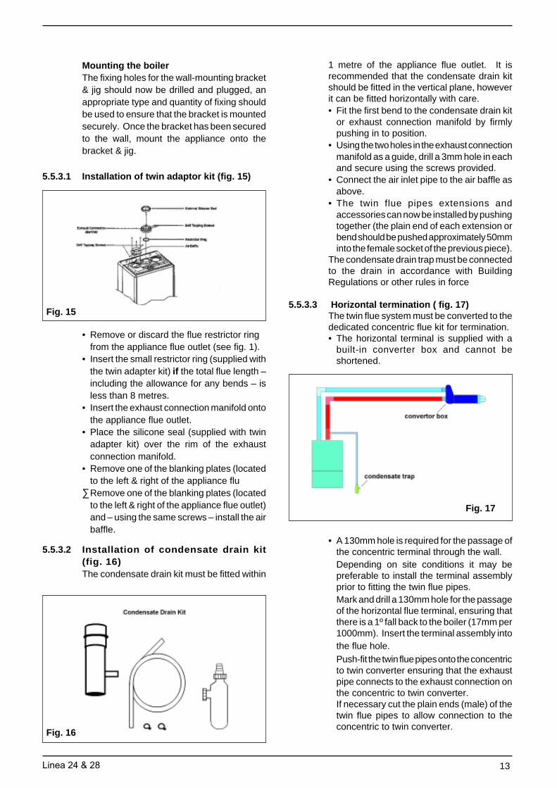
5.5.3.1 Installation of twin adaptor kit (fig. 15)
• Remove or discard the flue restrictor ringfrom the appliance flue outlet (see fig. 1).
• Insert the small restrictor ring (supplied withthe twin adapter kit) if the total flue length –including the allowance for any bends – isless than 8 metres.
• Insert the exhaust connection manifold ontothe appliance flue outlet.
• Place the silicone seal (supplied with twinadapter kit) over the rim of the exhaustconnection manifold.
• Remove one of the blanking plates (locatedto the left & right of the appliance flu
∑Remove one of the blanking plates (locatedto the left & right of the appliance flue outlet)and – using the same screws – install the airbaffle.
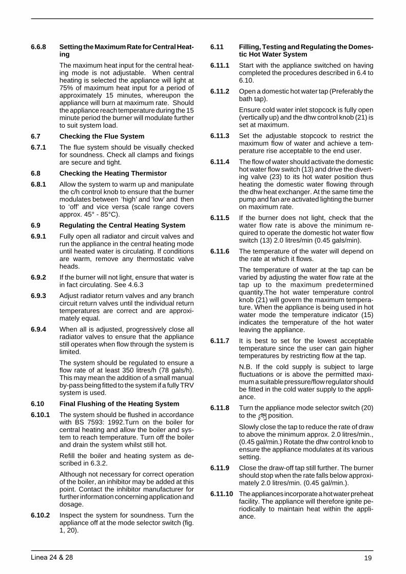
5.5.3.2 Installation of condensate drain kit(fig. 16)The condensate drain kit must be fitted within
Fig. 15
Fig. 16
1 metre of the appliance flue outlet. It isrecommended that the condensate drain kitshould be fitted in the vertical plane, howeverit can be fitted horizontally with care.• Fit the first bend to the condensate drain kit
or exhaust connection manifold by firmlypushing in to position.
• Using the two holes in the exhaust connectionmanifold as a guide, drill a 3mm hole in eachand secure using the screws provided.
• Connect the air inlet pipe to the air baffle asabove.
• The twin flue pipes extensions andaccessories can now be installed by pushingtogether (the plain end of each extension orbend should be pushed approximately 50mminto the female socket of the previous piece).
The condensate drain trap must be connectedto the drain in accordance with BuildingRegulations or other rules in force
5.5.3.3 Horizontal termination ( fig. 17)The twin flue system must be converted to thededicated concentric flue kit for termination.• The horizontal terminal is supplied with a
built-in converter box and cannot beshortened.
• A 130mm hole is required for the passage ofthe concentric terminal through the wall.Depending on site conditions it may bepreferable to install the terminal assemblyprior to fitting the twin flue pipes.Mark and drill a 130mm hole for the passageof the horizontal flue terminal, ensuring thatthere is a 1º fall back to the boiler (17mm per1000mm). Insert the terminal assembly intothe flue hole.Push-fit the twin flue pipes onto the concentricto twin converter ensuring that the exhaustpipe connects to the exhaust connection onthe concentric to twin converter.If necessary cut the plain ends (male) of thetwin flue pipes to allow connection to theconcentric to twin converter.
Fig. 17
14 Linea 24 & 28
NOTE• Before cutting twin flue pipes ensure
allowances have been made for connectiononto the previous piece and onto theconcentric to twin converter. The last twinflue pipes must be pushed 50mm onto themale spigots of the concentric to twinconverter.
NOTEYou must ensure that the entire flue system isproperly supported and connected.
When cutting an extension to the requiredlength, you should ensure that the excess iscut from the plain end of the extension. Removeany burrs, and check that both seals arelocated properly.
Seal the flue terminal assembly to the wallusing cement or a suitable alternative that willprovide satisfactory weatherproofing. Theinterior and exterior trim can now be fitted.
5.5.3.4 Vertical termination (See fig. 18)The twin flue system must be converted to thededicated concentric flue kit for termination.• The vertical terminal is supplied with a built-
in converter box and cannot be shortened.• A 130mm hole is required for the passage of
the concentric terminal through the ceilingand/or roof.
Depending on site conditions it may bepreferable to install the terminal assemblyprior to fitting the twin flue pipes.
Fit the appropriate flashing plate to the roofand insert the vertical flue terminal through theflashing plate from the outside, ensuring thatthe collar on the flue terminal fits over theflashing.
Push-fit the twin flue pipes onto the concentricto twin converter ensuring that the exhaustpipe connects to the exhaust connection onthe concentric to twin converter.If necessary cut the plain ends (male) of thetwin flue pipes to allow connection to theconcentric to twin converter.
NOTE• Before cutting twin flue pipes ensure
allowances have been made for connectiononto the previous piece and onto theconcentric to twin converter. The last twinflue pipes must be pushed 50mm onto themale spigots of the concentric to twinconverter.
• You must ensure that the entire flue systemis properly supported and connected.
• Ensure that any horizontal sections of pipehave a 1º fall towards the appliance (17mmper 1000mm).
• The convertor box on the vertical terminalwill have to be temporarily removed wheninserting the terminal through the flashing.
• The condensate trap must be primed withwater prior to commissioning the boiler.
• The condensate drain trap must beconnected to the drain in accordance withbuilding regulations or other rules in force.
Fig. 18
Linea 24 & 28 15
5.6 Connecting the Gas and Water
5.6.1 Figs. 6 and 16 show the locations of thefittings.
5.6.2 Do not over tighten nuts, use another spannerto apply counter force to avoid damaging theappliance
5.6.3 Gas SupplyConnecting the gas supply.
Connect a 15mm gas pipe to the gas servicetap and tighten the union nut securing the tapto the appliance.
Pipework from the meter to the appliancemust be of adequate size.
A minimum gas pressure of 20mb (8 in. w.g.)must be available at the appliance inlet at fullflow rate. See section 3.
DO NOT use pipes of a smaller size than theappliance inlet connection.
5.6.4 Central HeatingConnect the central heating pipework (22mmo.d) to the respective valves, right hand: flow,left hand: return, and tighten the nuts.
5.6.5 Hot WaterConnect a 15mm pipe to the hot water outletconnection of the appliance. Tighten the nut.
If the hot water system does not include a tapbelow the hot water outlet connection, providea suitable drain tap to permit draining of theappliance hot water side during servicing.
5.6.6 Cold WaterConnect a 15mm cold water service pipe tothe inlet stopcock of the appliance. Tighten thenut.
If the cold water supply is liable to high pres-sure or large pressure fluctuations, a flow/pressure regulator should be fitted in the sup-ply pipe.
Should the appliance be subject to 'mainsknock' it would be advisable to install a nonreturn valve in the hot water outlet pipe toprevent unnecessary activation of the domes-tic flow switch.
5.6.7 Safety Valve DischargeConnect a 15mm pipe to the discharge outletof the appliance.
The discharge should terminate facing down-wards outside the building in a position wheredischarging (possibly boiling) water will notcreate danger or nuisance; but in an easilyvisible position.
5.7 Electrical Connections
5.7.1 The electricity supply must be as specified in4.7. If controls external to the appliance arerequired, design of the external electrical cir-cuits should be undertaken by a competentperson.
See Section 10 for further advice.
N.B. IT IS ESSENTIAL THAT ALL EXTER-NAL CONTROL CIRCUITS AND WIRING ISWIRED FROM THE SAME ELECTRICAL ISO-LATOR AS SERVES THE APPLIANCE.
Factory fitted internal wiring must not be dis-turbed when wiring external controls.
5.7.2 To gain access to the electrical terminals
Remove electrical cover by releasing foursecuring screws. Fig.19.
The mains input terminal block is now easilyvisible (see fig. 19a).
5.7.3 The electricity supply cable from the isolatorand the appliance terminal block must be 3core flexible sized 0.75mm˝ (24 x 0.2mm) toBS6500.
Wiring to the appliance should be rated foroperation in contact with surfaces up to 90°C.
Electrical CoverScrews
Fig. 19
Fig. 19a
Mains Input andExternal Con-trols TerminalBlock
Factory FittedLink Between= & TA
EarthScrew
16 Linea 24 & 28
5.7.4 Pass the cable through one of the cord an-chorage points and connect the wires Brownto L, Blue to N, and Green/Yellow to. Arrange the cable so that should the cableslip the anchorage the current carrying con-ductors become taut before the earthing con-ductor.
5.7.5 Securely tighten all terminal screws and ar-range the cable with slack between the cableanchor and the terminal block. Tighten thecord anchorage screw until the cable is se-cure.
5.7.6 Neatly arrange the external cable in such away that unrestricted opening of the controlsfascia is possible without strain on the cable.
5.7.7 External controls may be wired from terminalsTA to TA after removing the factory fitted link(see fig. 19 & pages 49-52 for further details).If a neutral is needed use the terminal markedN on the terminal strip.
DO NOT CONNECT ANY WIRES TO THETERMINAL STRIP MARKED 'S' '-' 'POS' 'POS'
When connecting wires to the terminal strip itis possible to remove the terminal strip fromthe circuit board: Grasp the terminal stripfirmly and slide up to clear pcb. See fig.22.
When refitting the terminal strip it is importantthat it is replaced correctly (with the screwsfacing left).
Section 10 gives details of fitment for externaland internal controls (ie Vokèra time clock).
If required pass the external controls cablethrough the spare cord anchorage and ar-range the cable so that should the cable slipthe anchorage the current carrying conduc-tors become taut before the earthing conductor.
Fig.22 Do not connect wiresto this terminal strip
Controls terminalstrip
Fig.20
Fig.21
Main BurnerTest Point
Incoming GasPressure Test
Point
NormalOperatingPosition
FillingPosition
ClosedPosition
Linea 24 & 28 17
SECTION 6 COMMISSIONING
6.1 Where the text bears identifying numbers inbrackets, refer to figs. 1 and 2 unless other-wise instructed.
6.2 Gas Supply InstallationInspect the entire installation including themeter. Test for soundness and purge, all asdescribed in BS6891:1988.
6.3 Central Heating Systems
6.3.1 IMPORTANT DO NOT RELEASE AIR FROMTHE RED SEALED EXPANSION TANK. It ischarged with air at the factory from .75 - .80 bar(11 - 12psig)
6.3.2 Initial filling of the System
6.3.2.1 See 3.4.3.
6.3.2.2 Open central heating flow and return valves.Unscrew black cap on automatic air releasevalve (25) one full turn. (Leave open perma-nently).
6.3.2.3 Close all air release taps on the central heat-ing system.
6.3.2.4 Identify the filling/inlet valve found at the baseof the appliance. See fig.6.
The filling loop may have been disconnectedfrom the filling/inlet valve and heating flowvalve. If so reconnect unscrewing the caps asnecessary.The filling/inlet valve has 3 positions. (Fig. 21) i)Vertically up - normal operating position.ii) Turn to the left to horizontal - closed posi-tion.iii) Vertically down - Filling position.To fill, slowly turn the handle of the filling/inletvalve from the closed position towards thefilling position. Mains water will be heard toenter the system/boiler. As the water entersthe system/boiler the pressure gauge will beseen to rise. Pressurise to between 1bar &1.5bar when the system is cold. DO NOTOVERPRESSURISE.Once the desired pressure is achieved turnthe filling/inlet valve back to the closed posi-tion.
6.3.2.5 Starting with the lowest radiator open each airrelease tap in turn closing it only when clearwater, free of bubbles, flows out. In the sameaway release air from any high points in thepipework.
6.3.2.6 Continue filling the system until at least 1.0 barregisters on the gauge then turn the handle ofthe filling/inlet valve back to the closed posi-tion.
6.3.2.7 Inspect the system for water soundness andremedy any leaks discovered.
6.3.3 Initial flushing of Pipework
The whole of the heating system must beflushed both cold and later hot as detailed in6.10. Open all radiator or heating valves andthe appliance central heating valves. Drain theboiler and system from the lowest points.Open the drain valve full bore to remove anyinstallation debris from the boiler prior to light-ing. Refill the boiler and heating system asdescribed in 6.3.2
6.3.4 Setting the System Design Pressure
6.3.4.1 The design pressure should be a minimum of1 bar and maximum 1.5 bar.
6.3.4.2 The actual reading should ideally be 1 bar plusthe equivalent height in metres to the highestpoint of the system above the base of theappliance. (Up to the maximum of 1.5 bartotal).N.B. The safety valve is set to lift at 3bar/ 30m/ 45psig.
6.3.4.3 To lower the system pressure to the requiredvalue, pull lever on head of safety valve (22) aquarter turn to release water until the requiredfigure registers on the gauge (19).
6.3.5 Filling the Hot Water System
6.3.5.1 Close all hot water draw-off taps.
6.3.5.2 Turn filling/inlet valve to the normal operatingposition (vertically up). See fig. 21
6.3.5.3 Slowly open each draw-off until clear water isdischarged.
6.4 Checking Electricity Supply
6.4.1 Carry out preliminary checks for continuity,polarity, and resistance to earth (see page56), gaining access as required according to5.7.2 in this manual.
6.4.2 Leave the appliance with the control fasciaclosed and with the mains electricity switchedOFF
6.5 Lighting the Boiler
6.5.1 Ensure flow and return valves are open.(6.3.2.1)
If external and/or internal controls are fitted(e.g Timeclock and/or Room thermostat) en-sure they ‘call for heat’. The commissioning ofthe appliance may be easier if the external/internal controls are disconnected and termi-nals TA & TA are linked. (For access proce-dure turn off electricity and refer to 5.7.2 forinstructions).
6.5.2 Switch on the mains electricity and turn the on/ off / mode switch (20) to
6.5.3 Set the c/h control knob (16) to the highestsetting.
6.5.4 The appliance will go through an ignition se-quence and the burner will light.
18 Linea 24 & 28
6.5.5 If during the ignition attempt period (10 secsapprox.) the boiler fails to light, the ignitioncontrol circuit will go to lockout. This is indi-cated by the status LED (14) flashing redaccompanied by a flashing error code 01shown in the temperature indicator (15). Thegas valve is de-energised, but leaves the fanand pump running for approximately 2 min-utes after lockout.
6.5.6 In the event of the boiler going to lockout turnthe mode selector switch to the reset positionfor approximately 10 seconds, then back tothe original position. The two main causes ofthe boiler going to lockout during commissioningare electrical supply polarity reversed, or air inthe gas supply. Check polarity and that the gassupply is completely purged of air, and thatgas is reaching the boiler, then repeat from6.5.2.
6.6 Checking Burner Pressures
6.6.1 The heat inputs for high and low gas rates arefactory set to the maximum values given insection 3.6 for domestic hot water and centralheating but it is necessary to check them whencommissioning.
6.6.2 Turn off the main electricity supply. Gain ac-cess to the interior as instructed in 5.7.2.
6.6.3 Locate the main burner pressure test point(Fig. 20) and slacken the screw half a turn in ananti clockwise direction . Attach a suitable Ugauge tube between the test nipple and ma-nometer (see fig. 23).
IMPORTANT: Before measuring gas pres-sures it is imperitive that the protective coverover the gas valve adjustment screw is re-moved. (Fig. 37)
Turn on electricity supply and fully open adomestic hot water tap to operate boiler in dhwmode. Adjust hot water control knob to it'smaximum setting.
Allow boiler to operate for approximately 5- 10 minutes before checking gas pres-sures.
6.6.4 The pressure reading for maximum rate shouldbe:
24 (N/G)10.1mbar( plus or minus 1.0mbar)
28 (N/G)10.1mbar(plus or minus 1.0mbar)
If the pressure is wrong it should be adjustedas instructed in 8.23 (N.B. Whenever themaximum rate is adjusted, check and adjustthe minimum rate too)
6.6.5 Reduce the domestic water flow rate to approx.3-4 litres/min, turn the domestic control knobslowly to minimum. The boiler output willreduce to the minimum setting. If low flamecannot be established in this way, turn off theelectricity supply and remove one of the greywires connecting to the modulator coil on thefront of the gas valve. Switch on the electricitysupply. The boiler will now light at the mini-mum setting.
6.6.6 When low flame is established, the pressurereading should be:
24 (N/G)1.5mbar(plus or minus 0.15mbar)
28 (N/G)1.3mbar(plus or minus 0.13mbar)
If it is different adjustment should be made inaccordance with the instructions in 8.23.
6.6.7 If the grey wire from the modulator coil wasremoved to check the minimum setting, turnoff the electricity supply and replace the wireonto the modulator coil.
Fig.23
U Gauge Tube
Manometer
Gas Valve
Linea 24 & 28 19
6.6.8 Setting the Maximum Rate for Central Heat-ing
The maximum heat input for the central heat-ing mode is not adjustable. When centralheating is selected the appliance will light at75% of maximum heat input for a period ofapproximately 15 minutes, whereupon theappliance will burn at maximum rate. Shouldthe appliance reach temperature during the 15minute period the burner will modulate furtherto suit system load.
6.7 Checking the Flue System
6.7.1 The flue system should be visually checkedfor soundness. Check all clamps and fixingsare secure and tight.
6.8 Checking the Heating Thermistor
6.8.1 Allow the system to warm up and manipulatethe c/h control knob to ensure that the burnermodulates between ‘high’ and ‘low’ and thento ‘off’ and vice versa (scale range coversapprox. 45° - 85°C).
6.9 Regulating the Central Heating System
6.9.1 Fully open all radiator and circuit valves andrun the appliance in the central heating modeuntil heated water is circulating. If conditionsare warm, remove any thermostatic valveheads.
6.9.2 If the burner will not light, ensure that water isin fact circulating. See 4.6.3
6.9.3 Adjust radiator return valves and any branchcircuit return valves until the individual returntemperatures are correct and are approxi-mately equal.
6.9.4 When all is adjusted, progressively close allradiator valves to ensure that the appliancestill operates when flow through the system islimited.
The system should be regulated to ensure aflow rate of at least 350 litres/h (78 gals/h).This may mean the addition of a small manualby-pass being fitted to the system if a fully TRVsystem is used.
6.10 Final Flushing of the Heating System
6.10.1 The system should be flushed in accordancewith BS 7593: 1992.Turn on the boiler forcentral heating and allow the boiler and sys-tem to reach temperature. Turn off the boilerand drain the system whilst still hot.
Refill the boiler and heating system as de-scribed in 6.3.2.
Although not necessary for correct operationof the boiler, an inhibitor may be added at thispoint. Contact the inhibitor manufacturer forfurther information concerning application anddosage.
6.10.2 Inspect the system for soundness. Turn theappliance off at the mode selector switch (fig.1, 20).
6.11 Filling, Testing and Regulating the Domes-tic Hot Water System
6.11.1 Start with the appliance switched on havingcompleted the procedures described in 6.4 to6.10.
6.11.2 Open a domestic hot water tap (Preferably thebath tap).
Ensure cold water inlet stopcock is fully open(vertically up) and the dhw control knob (21) isset at maximum.
6.11.3 Set the adjustable stopcock to restrict themaximum flow of water and achieve a tem-perature rise acceptable to the end user.
6.11.4 The flow of water should activate the domestichot water flow switch (13) and drive the divert-ing valve (23) to its hot water position thusheating the domestic water flowing throughthe dhw heat exchanger. At the same time thepump and fan are activated lighting the burneron maximum rate.
6.11.5 If the burner does not light, check that thewater flow rate is above the minimum re-quired to operate the domestic hot water flowswitch (13) 2.0 litres/min (0.45 gals/min).
6.11.6 The temperature of the water will depend onthe rate at which it flows.
The temperature of water at the tap can bevaried by adjusting the water flow rate at thetap up to the maximum predeterminedquantity.The hot water temperature controlknob (21) will govern the maximum tempera-ture. When the appliance is being used in hotwater mode the temperature indicator (15)indicates the temperature of the hot waterleaving the appliance.
6.11.7 It is best to set for the lowest acceptabletemperature since the user can gain highertemperatures by restricting flow at the tap.
N.B. If the cold supply is subject to largefluctuations or is above the permitted maxi-mum a suitable pressure/flow regulator shouldbe fitted in the cold water supply to the appli-ance.
6.11.8 Turn the appliance mode selector switch (20)to the position.
Slowly close the tap to reduce the rate of drawto above the minimum approx. 2.0 litres/min.,(0.45 gal/min.) Rotate the dhw control knob toensure the appliance modulates at its varioussetting.
6.11.9 Close the draw-off tap still further. The burnershould stop when the rate falls below approxi-mately 2.0 litres/min. (0.45 gal/min.).
6.11.10 The appliances incorporate a hot water preheatfacility. The appliance will therefore ignite pe-riodically to maintain heat within the appli-ance.
20 Linea 24 & 28
6.12 Final Check for Operations
Turn mode selector switch to the OFF/RESETposition, disconnect pressure gauge, re-tightenscrew. Relight boiler.
6.12.1 Re-check for gas soundness
6.12.2 Re examine heating and hot water systemsand cold water supply for water soundness.
6.12.3 Check the appearance of the gas flame toassess adequacy of combustion air supply.
6.12.4 Re-check the flue system for soundness andadequacy of supports.
6.13 Concluding Operations
6.13.1 If external/internal controls have been discon-nected and terminals TA & TA temporarilylinked, remove the link and reconnect thecontrols circuit. Check the operation of thecontrols.
6.14 Refixing the boiler casing (fig. 25).
6.14.1 Offer up the front casing to the back frame ina near vertical attitude and locate the hooks onthe casing over the hooks on the frame.
Slide the casing downwards to fully engagethe hooks and to align the bottom fixing holes.Replace the two case retaining screws. (fig.25)
6.14.2 Hinge up the control fascia and secure usingthe two screws. (fig.26)
6.14.3 Disconnect filling loop, fit filling loop cap. Leavefilling loop in a safe and accessible place.
6.15 Supplementary Instructions for Fitting & Re-moving Optional Time Clock and for Wiring toExternal Controls.
Section 10 Appendices A and B at the rear ofthis manual provides full instruction for fittingand wiring the optional built-in time switchesand for wiring to external controls.
6.16 Complete details of the boiler, controls, instal-lation and commissioning in the log booksupplied with the boiler. This is an importantdocument which must be correctly completedand handed to the user. Failure to install andcommission this appliance to the manufactur-ers instructions may invalidate the warranty.
SECTION 7 INSTRUCTING THE USER
7.1 Hand over the copy of the Users Instructionsand boiler log book supplied with the appli-ance, together with these instructions. Explainhow to operate the boiler correctly and how touse the timeclock and room thermostat if fitted.
7.2 Show the user how to switch off the applianceand indicate the position of the electric supplyisolator.
7.3 Inform the user of the location of all draincocks and air vents.
7.4 Explain how to turn the appliance off for bothshort and long periods and advise on theprecautions necessary to prevent damageshould the appliance be inoperative whenfreezing conditions may occur.
7.5 Show the user the filling loop position itsfunction and how to repressurise the systemusing the filling/inlet valve.
7.6 Advise the user that, for continued safe andefficient operation, the appliance must be serv-iced by a competent person at least once ayear.
Fig. 25 Fig. 26
Case Screws
Case screws(one either side)
Linea 24 & 28 21
SECTION 8 SERVICING INSTRUCTIONS
8.1 General
To ensure the continued safe and efficientoperation of the appliance, it is recommendedthat it is checked and serviced as necessary atregular intervals.
The frequency of servicing will depend uponthe particular installation conditions and us-age, but in general, once per year should beadequate.
It is the law that any servicing work is carriedout by a competent person such as a Vokèraservice engineer, approved service agent,British Gas or other CORGI registered per-sonnel.
The following instructions apply to the boilerand its controls, but it should be rememberedthat the central heating and domestic hotwater systems will also require attention fromtime to time.
8.2 Important Notes
WARNING: having carried out preliminaryflame checks and before starting any servic-ing work, switch OFF the mains electricitysupply and disconnect the plug at the mainisolating switch and socket. (If a switch is usedremove the fuse.)
Turn off gas supply at the gas service tap fittedto the appliance.
Always test for gas soundness after any serv-ice work and after exchanging any gas carry-ing component.
8.3 Recommended Routine Servicing
8.3.1 Annual Servicing
When servicing is required the following pro-cedures should be carried out.
1. Inspect exterior for signs of damage anddeterioration, particularly of flue pipeworkand electrical connections.
2. Turn off mains electricity and remove frontcasing (see 8.4.).
3. Replace fuse if previously removed ( 8.2.above) and turn on electricity. Run theboiler for a few minutes in the domestic hotwater mode to permit inspection of itsoperation. This is accomplished by open-ing a domestic hot water draw off tap andinspecting burner for yellowing of flame tip,flame lift off or sooting.
4. Ensure central heating valves are open.See 6.3.2.1.
Observe pressure gauge reading (fig. 1,19) which should be approximately 1 barwhen the system is cold See 6.3.4
5. Turn off mains electricity and turn off gasservice tap on the appliance.
6. Gain general access as described in8.4.
7. Remove main burner (see 8.6). Lightlyclean with a soft brush and inspect fordamage. If during initial inspection anycombustion irregularity was suspected,remove injectors and clean or replace (see8.7).
8. Place cloth below combustion chamber tocatch debris. Clean heat exchanger usingsuitable brushes and rods if necessary.
9. Inspect combustion chamber lining. Theinsulating material is easily damaged. Donot scrape, but clean off lightly.
If any panels are damaged these should bereplaced (see 8.11).
10. Replace all parts in reverse order but leavethe controls fascia open and outer casingoff.
11.Undertake a complete commissioningcheck as detailed in section 6.
12.Close up control fascia and refix frontcasing.
13.Clean off casing using soft cloth and dilutedetergent.
14.Complete details of service undertaken inthe boiler log book.
NOTE: there is a flue gas analysis testpoint incorporated in the flue outlet. (see8.23.6 and fig. 1, 30)
8.3.2 Replacement of Parts
1. The life of individual components variesand they will need servicing as and whenfaults develop. The fault finding sequencecharts in section 9 will serve to locatewhich component is the cause of anymalfunction. Instructions for removal, in-spection and replacement of the individualparts are given in the following pages.
2. The domestic hot water heat exchangermay in certain conditions become partiallyblocked by scale deposits. Evidence of thiswill be deterioration in performance.
This condition could well be treated usingproprietary descalants following makers'instructions without dismantling the appli-ance by circulating a fluid through the dhwcoil. To do this, disconnection from hot andcold services is necessary. Reconnect onlyafter thorough flushing with clean water.
3. Occasional maintenance of mechanicalworking parts will be necessary. Servicekits are available from ypur local Vokèrastockists.
22 Linea 24 & 28
8.4 To Gain General Access/Assembly
To remove components access to the interioris essential. Refer to figs. 10 & 11.
Ensure electricity supply is isolated beforecarrying out any servicing.
8.4.1 To remove front casing.
Push to release front door panel and lower toreveal controls. Loosen the 2 captive screwssecuring the front control panel to the lowerpart of the casing and lower to reveal inside ofboiler. (fig. 10)
Remove two screws at base of casing, slightlylift the casing and slide it gently towards thetop of the appliance to disengage the casefrom the top suspension hooks. (Fig. 11)
Ensure the casing and screws are put to oneside in a safe place.
8.4.2 Reassembly is always carried out in reverseorder to dismantling, unless otherwise stated.Electrical connections must be remade inaccordance with the wiring diagram(figs.40,41,42 & 43).
8.4.3 Where gas control components are replaced,check the burner pressures and adjust if nec-essary. See 8.23.
8.5 Room Sealed Chamber Front CoverRefer to fig. 27.
8.5.1 Gain general access as 8.4
8.5.2 Remove room sealed cover plate by releasingtwo lower retaining clips and easing cover offthe top locating hooks. Inspect gasket fordamage. If damaged, replace.
NOTE: When refitting the combustion cham-ber front cover it is essential to correctly seatand secure the cover in place ensuring bothclips are secured in place.
Fig. 28 b
Fig. 27
Fig. 28 a
Flue gas analysistest point
Fig. 28 c
Linea 24 & 28 23
8.6 Main Burner and ElectrodesPart No'sSense Electrode - 24&28 - 2092Refer to figs. 27,28 & 29
8.6.1 Gain general access as 8.4.
8.6.2 Remove room sealed front cover as 8.5
8.6.3 Remove front of combustion chamber by re-leasing screws (fig. 28).
8.6.4 Remove four burner retaining screws (fig. 30).Ease burner forward and rest on chamberbase (fig. 29).
8.6.5 Release electrode and earth retaining screws& carefully remove electrode.
8.6.6 Trace electrode and earth lead to electronicignition control and gas valve and disconnect
8.6.7 Remove main burner.
8.6.8 Reassemble in reverse order ensuring cor-rect location of electrode, and solid earthingpoint.
Note: If difficulty is found in relocating theburner securing screws, easier access can begained by removing the two side panels(fig. 29).
8.7 Main Burner Injectors
8.7.1 Gain general access as 8.4
8.7.2 Remove room sealed front cover plate andcombustion chamber front (8.5 & 8.6.3).
8.7.3 Remove main burner (8.6.4 to 8.6.8).
8.7.4 Unscrew injector(s) from burner bar.
8.8 Main Heat Exchanger
Part No's 24- 2371, 28-2378Refer to Fig. 30
8.8.1 Gain general access as 8.4
8.8.2 Remove room sealed front cover plate (8.5).
8.8.3 Remove front of combustion chamber (8.6.3).
8.8.4 Remove two air baffle plates, 1 screw securingeach (fig. 31).
8.8.5 Remove electrical plug from primary thermistor
Remove both side panels, 2 screws each(fig. 29)
8.8.6 Close heating flow and return valves by turn-ing 1/4 turn until indicating lines are horizon-tal. Pull lever on head of safety valve to drainprimary circuit to boiler.
8.8.7 Place cloth under heat exchanger to catchsurplus water.
8.8.8 Unscrew unions on either side of main heatexchanger fig. 30.
8.8.9 Slide out main heat exchanger, taking carenot to damage insulation panels. Avoid spill-age of water on boiler electrics.
8.8.10 Reassemble in reverse order using new fibrewashers in unions.
Fig. 29
Fig. 30
SidePanelScrew
Fig. 29 a
24 Linea 24 & 28
8.9 Flue FanPart No. 24-5910 28-5911
8.9.1 Remove room sealed front cover plate (8.5)and front of combustion chamber (8.6.3).
8.9.2 Loosen maintenance clip securing screws(see fig. 31) and slide upwards to clear joint.
8.9.3 Remove silicone pipes from nozzles on innerflue bend
8.9.4 Remove 5 flue hood retaining screws (see fig.31).
NOTE: When removing the two side screwsthe two air baffle plates can be removed.
8.9.5 Carefully slide flue hood forward disconnectingelectrical leads on fan in the process.
8.9.6 Unscrew 4 screws securing fan to flue hoodand remove fan. Transfer aluminiummanifold (two screws) to new fan.
8.9.7 Reassemble in reverse order, replacing cen-tre hood screw first.
8.10 Flue Pressure Differential SwitchPart No 24&28-9232Refer to Fig. 31
8.10.1 Gain general access as 8.4
8.10.2 Remove room sealed cover (8.5)
8.10.3 Remove 2 screws holding pressure differen-tial switch to the combustion chamber.
8.10.4 Pull off tab connectors and remove pressureswitch, disconnecting the air pressure pipes inthe process.
8.10.5 Reassemble in reverse order.
See fig. 41&43 for correct fitting of electricalconnections. When reconnecting the pres-sure pipes the upper nozzle on the inner fluebend connects to:The front nozzle of the pressure differentialswitch.
8.11 Combustion Chamber Insulation Boards
8.11.1 Gain general access as 8.4
8.11.2 Remove room sealed front cover 8.5Remove front of combustion chamber 8.6.3.
Remove Main Heat Exchanger 8.8.
8.11.3 To remove side combustion chamber insula-tion boards, gently prise upwards and pull out.
8.11.4 To remove rear board, gently prise upwardsand pull out.
8.11.5 Fourth panel (front) is replaced complete withcombustion chamber front panel.
Fig. 31
HoodRetainingScrews
Airbaffleplate
Maintenance clip
Pressuredifferential switch
Airtubes
Airbaffleplate
Linea 24 & 28 25
8.12 Ignition PCB
8.12.1 Gain general access as 8.4.
8.12.2 Remove PCB cover.
8.12.3 Disconnect wires from ignition PCB.
8.12.4 Remove ignition PCB.
8.12.5 Replace in the reverse order ensuring wiresare replaced correctly.
8.13 Gas Control Valve (complete)Part No. 24&28- 1836 fig. 32
8.13.1 Turn off gas service tap.
8.13.2 Remove Ignition control box as 8.12
8.13.3 Pull off silicone tube from gas valve regulator.
8.13.4 Disconnect earth leads from gas valve.
8.13.5 Disconnect wires from modulator coil.
8.13.6 Unscrew gas service tap union & release fromits seating.
8.13.7 Remove 2 screws securing gas valve bracketto the base frame.
8.13.8 Undo union above the gas control valve &withdraw gas valve.
8.13.9 Reassemble in reverse order.
8.13.10 Test all joints for gas soundness.
8.13.11 Check burner pressures. As detailed in 6.6If incorrect adjust as instructed in 8.23.
PumpSecuringBracket
Silicon PipeConnection Point
ModulatorCoil
Fig. 32
Fig. 33
Pipe Securing Clip
26 Linea 24 & 28
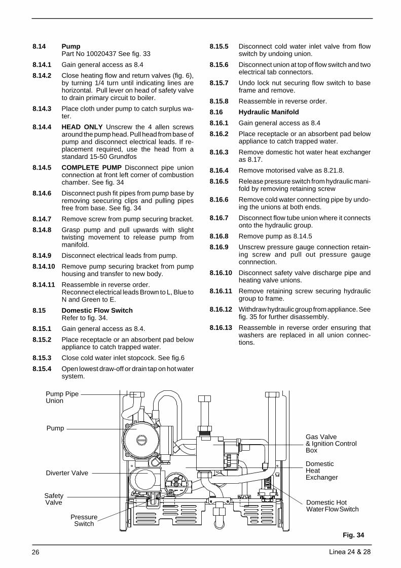
8.14 PumpPart No 10020437 See fig. 33
8.14.1 Gain general access as 8.4
8.14.2 Close heating flow and return valves (fig. 6),by turning 1/4 turn until indicating lines arehorizontal. Pull lever on head of safety valveto drain primary circuit to boiler.
8.14.3 Place cloth under pump to catch surplus wa-ter.
8.14.4 HEAD ONLY Unscrew the 4 allen screwsaround the pump head. Pull head from base ofpump and disconnect electrical leads. If re-placement required, use the head from astandard 15-50 Grundfos
8.14.5 COMPLETE PUMP Disconnect pipe unionconnection at front left corner of combustionchamber. See fig. 34
8.14.6 Disconnect push fit pipes from pump base byremoving seecuring clips and pulling pipesfree from base. See fig. 34
8.14.7 Remove screw from pump securing bracket.
8.14.8 Grasp pump and pull upwards with slighttwisting movement to release pump frommanifold.
8.14.9 Disconnect electrical leads from pump.
8.14.10 Remove pump securing bracket from pumphousing and transfer to new body.
8.14.11 Reassemble in reverse order.Reconnect electrical leads Brown to L, Blue toN and Green to E.
8.15 Domestic Flow SwitchRefer to fig. 34.
8.15.1 Gain general access as 8.4.
8.15.2 Place receptacle or an absorbent pad belowappliance to catch trapped water.
8.15.3 Close cold water inlet stopcock. See fig.6
8.15.4 Open lowest draw-off or drain tap on hot watersystem.
8.15.5 Disconnect cold water inlet valve from flowswitch by undoing union.
8.15.6 Disconnect union at top of flow switch and twoelectrical tab connectors.
8.15.7 Undo lock nut securing flow switch to baseframe and remove.
8.15.8 Reassemble in reverse order.
8.16 Hydraulic Manifold
8.16.1 Gain general access as 8.4
8.16.2 Place receptacle or an absorbent pad belowappliance to catch trapped water.
8.16.3 Remove domestic hot water heat exchangeras 8.17.
8.16.4 Remove motorised valve as 8.21.8.
8.16.5 Release pressure switch from hydraulic mani-fold by removing retaining screw
8.16.6 Remove cold water connecting pipe by undo-ing the unions at both ends.
8.16.7 Disconnect flow tube union where it connectsonto the hydraulic group.
8.16.8 Remove pump as 8.14.5
8.16.9 Unscrew pressure gauge connection retain-ing screw and pull out pressure gaugeconnnection.
8.16.11 Remove retaining screw securing hydraulicgroup to frame.
8.16.12 Withdraw hydraulic group from appliance. Seefig. 35 for further disassembly.
8.16.13 Reassemble in reverse order ensuring thatwashers are replaced in all union connec-tions.
Gas Valve& Ignition ControlBox
Domestic HotWater Flow Switch
SafetyValve
Pump
PressureSwitch
DomesticHeatExchanger
Fig. 34
Pump PipeUnion
Diverter Valve
Linea 24 & 28 27
8.17 Removal of Domestic Hot Water HeatExchangerRefer to figs. 34 and 35
8.17.1 Gain General access 8.4
8.17.2 Place receptacle or an absorbent pad belowappliance to catch trapped water.
8.17.3 Close cold water inlet stopcock. See fig. 6
8.17.4 Open lowest draw-off or drain tap on hot watersystem.
8.17.5 Close heating flow and return valves (fig. 6) byturning 1/4 turn until indicating lines are hori-zontal. Pull lever on head of safety valve todrain primary circuit to boiler.
8.17.7 Gently release heat exchanger from O' ringseals by rocking to the rear and remove.
8.17.8 Remove insulation jacket and transfer to newdomestic heat exchanger.
8.17.9 Reassemble in reverse order, using new O'rings if required.
8.18 Diverter Valve
8.18.1 Gain general access as 8.4.
8.18.2 Close heating flow and return valves (fig. 6) byturning 1/4 turn until indicating lines are hori-zontal. Pull lever on head of safety valve todrain primary circuit to boiler.
8.18.3 Remove motorised valve. See 8.21.8
8.18.4 Remove front of diverter valve by unscrewingsix retaining bolts.
8.18.5 See Fig.35 for further disassembly and loca-tion of components.
8.18.6 Reassemble in reverse order.
8.19 Checking/Replacing Main Expansion Ves-sel
8.19.1 The expansion vessel is factory pressurised0.8 bar (12psig) and should be checked dur-ing servicing. Should it have lost pressure itcan be repressurised in situ. Drain the boiler.Fit a suitable pump and gauge (i.e. car footpump and gauge) to the nipple at the top right-hand side of the expansion vessel, and pres-surise to 0.8bar (12psig) and remove thepump.
NOTE: Access to the nipple can be improvedby removing the upper vessel retaining bracketand rocking the vessel forwards.
If the vessel cannot be repressurised or ifpressure loss is very frequent the expansionvessel will require changing. Alternatively, anew vessel can be fitted in the return to theappliance, and the old vessel isolated in situ.
8.19.2 Switch OFF mains electricity and gain generalaccess. Disconnect electricity supply and wir-ing for external controls from the appliance.See 5.7
8.19.3 Close heating flow and return valves (fig. 6) byturning 1/4 turn until indicating lines are hori-zontal. Pull lever on head of safety valve todrain primary circuit to boiler.
8.19.4 Remove screws on large maintenanceclip/s (fig. 14) and remove. Loosen screws onthe small clip/s and disconnect flue.
8.19.5 Disconnect all pipe unions at the base of theappliance.
8.19.6 Lift appliance off upper bracket.
8.19.7 Remove two screws retaining vessel securingstrap at top. Disconnect expansion pipe atbase of expansion vessel and lift vessel out ofthe appliance.
8.19.8 Reassemble in reverse order, using new fibrewashers.
28 Linea 24 & 28
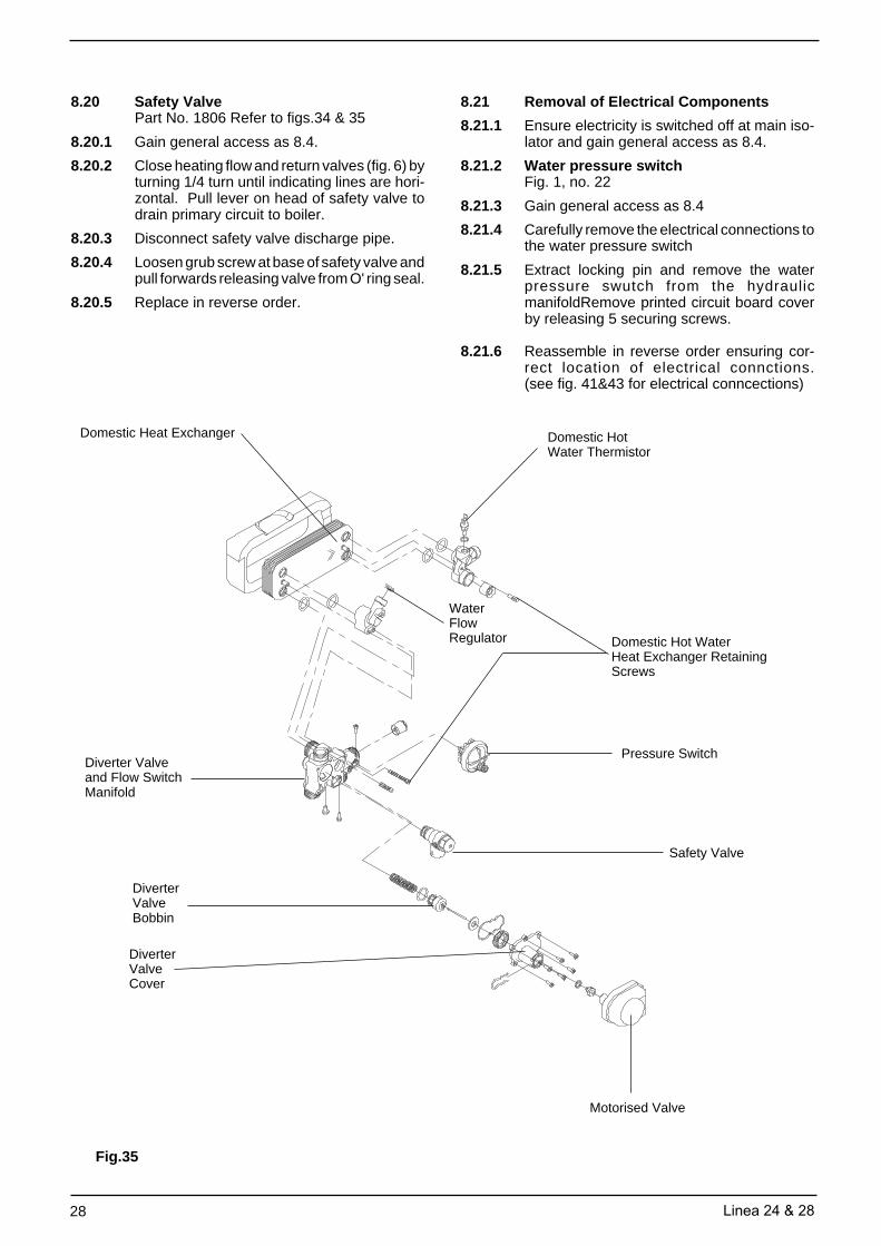
8.20 Safety ValvePart No. 1806 Refer to figs.34 & 35
8.20.1 Gain general access as 8.4.
8.20.2 Close heating flow and return valves (fig. 6) byturning 1/4 turn until indicating lines are hori-zontal. Pull lever on head of safety valve todrain primary circuit to boiler.
8.20.3 Disconnect safety valve discharge pipe.
8.20.4 Loosen grub screw at base of safety valve andpull forwards releasing valve from O' ring seal.
8.20.5 Replace in reverse order.
8.21 Removal of Electrical Components
8.21.1 Ensure electricity is switched off at main iso-lator and gain general access as 8.4.
8.21.2 Water pressure switchFig. 1, no. 22
8.21.3 Gain general access as 8.4
8.21.4 Carefully remove the electrical connections tothe water pressure switch
8.21.5 Extract locking pin and remove the waterpressure swutch from the hydraulicmanifoldRemove printed circuit board coverby releasing 5 securing screws.
8.21.6 Reassemble in reverse order ensuring cor-rect location of electrical connctions.(see fig. 41&43 for electrical conncections)
8.21.17 Reassemble in reverse order ensuring cor-rect location of electrical connections.(see fig. 41&43 for electrical connections)
NOTE: It will also be necessary to check/adjust the c/h gas pressure as 8.23.
8.21.18 Display Printed Circuit Board
8.21.19 Remove printed circuit board as 8.21.13 to8.21.18.
8.21.20 Remove three control knobs from front controlpanel.
8.21.21 Remove the two screws securing the circuitboard to the front panel.
8.21.22 Pull out two multi-plug connectors.
8.21.23 Replace in reverse order.
8.21.24 Safety ThermostatPart No 8367 (Refer to fig. 36)
8.21.25 Gain general access as 8.4.
8.21.26 Remove room sealed chamber front cover as8.5 and R/H side panel (fig. 29).
8.21.27 Pull off the two electrical connections on theback of the thermostat.
8.21.28 Release stat from flow pipe by unscrewing 2retaining screws.
8.21.29 Reassemble in reverse order ensuring cor-rect location of electrical connections.(see fig. 41&43 for electrical connections)
8.21.30 Thermistor SensorsPart No. 8484 Refer to fig.36
8.21.31 Gain general access as 8.4.
8.21.32 Remove room sealed chamber front cover as8.5. Remove R/H side panel as fig.29
8.21.32a PRIMARYClose heating flow and return valves (fig. 6) byturning 1/4 turn until indicating lines are hori-zontal. Pull lever on head of safety valve todrain primary circuit to boiler.
8.21.32b DOMESTIC HOT WATERClose cold water inlet stopcock. See fig.6 and6.3.3.4.
Open lowest draw-off or drain tap on hot watersystem.
8.21.33 Remove ignition control box as 8.12
8.21.34 Pull off electrical plug connection from ther-mistor.
8.21.35 Unscrew thermistor from pocket.
8.21.36 Reassemble in reverse order.
8.22 Pressure GaugePart No 1857
8.22.1 Gain general access as 8.4
8.22.2 Close heating flow and return valves (fig.6) byturning 1/4 turn until indicating lines are hori-zontal. Pull lever on head of safety valve todrain primary circuit to boiler.
8.22.3 Trace capillary from back of pressure gaugeto connecting point on brass manifold.
8.22.4 Unscrew the retaining screw beside the cap-illary tube entry to the manifold.
8.22.7 Reassemble in reverse order following origi-nal route for capillary tubes and ensuringlocking lugs are located in the grooves.
Fig. 36
Flow Pipe
Safety Thermostat
PrimaryThermistor
30 Linea 24 & 28
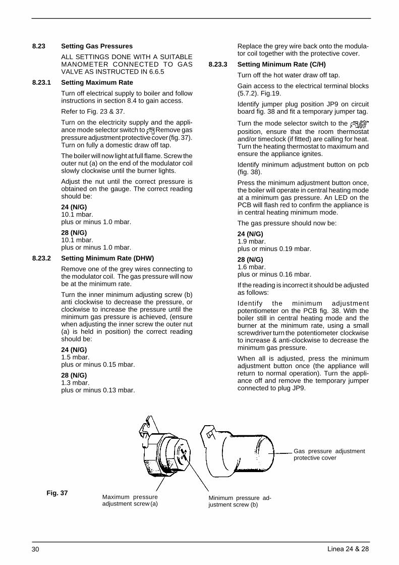
8.23 Setting Gas Pressures
ALL SETTINGS DONE WITH A SUITABLEMANOMETER CONNECTED TO GASVALVE AS INSTRUCTED IN 6.6.5
8.23.1 Setting Maximum Rate
Turn off electrical supply to boiler and followinstructions in section 8.4 to gain access.
Refer to Fig. 23 & 37.
Turn on the electricity supply and the appli-ance mode selector switch to Remove gaspressure adjustment protective cover (fig. 37).Turn on fully a domestic draw off tap.
The boiler will now light at full flame. Screw theouter nut (a) on the end of the modulator coilslowly clockwise until the burner lights.
Adjust the nut until the correct pressure isobtained on the gauge. The correct readingshould be:
24 (N/G)10.1 mbar.plus or minus 1.0 mbar.
28 (N/G)10.1 mbar.plus or minus 1.0 mbar.
8.23.2 Setting Minimum Rate (DHW)
Remove one of the grey wires connecting tothe modulator coil. The gas pressure will nowbe at the minimum rate.
Turn the inner minimum adjusting screw (b)anti clockwise to decrease the pressure, orclockwise to increase the pressure until theminimum gas pressure is achieved, (ensurewhen adjusting the inner screw the outer nut(a) is held in position) the correct readingshould be:
24 (N/G)1.5 mbar.plus or minus 0.15 mbar.
28 (N/G)1.3 mbar.plus or minus 0.13 mbar.
Replace the grey wire back onto the modula-tor coil together with the protective cover.
8.23.3 Setting Minimum Rate (C/H)
Turn off the hot water draw off tap.
Gain access to the electrical terminal blocks(5.7.2). Fig.19.
Identify jumper plug position JP9 on circuitboard fig. 38 and fit a temporary jumper tag.
Turn the mode selector switch to the position, ensure that the room thermostatand/or timeclock (if fitted) are calling for heat.Turn the heating thermostat to maximum andensure the appliance ignites.
Identify minimum adjustment button on pcb(fig. 38).
Press the minimum adjustment button once,the boiler will operate in central heating modeat a minimum gas pressure. An LED on thePCB will flash red to confirm the appliance isin central heating minimum mode.
The gas pressure should now be:
24 (N/G)1.9 mbar.plus or minus 0.19 mbar.
28 (N/G)1.6 mbar.plus or minus 0.16 mbar.
If the reading is incorrect it should be adjustedas follows:
Identify the minimum adjustmentpotentiometer on the PCB fig. 38. With theboiler still in central heating mode and theburner at the minimum rate, using a smallscrewdriver turn the potentiometer clockwiseto increase & anti-clockwise to decrease theminimum gas pressure.
When all is adjusted, press the minimumadjustment button once (the appliance willreturn to normal operation). Turn the appli-ance off and remove the temporary jumperconnected to plug JP9.
Fig. 37
Gas pressure adjustmentprotective cover
Maximum pressureadjustment screw (a)
Minimum pressure ad-justment screw (b)
Linea 24 & 28 31
8.24 Soft Light Ignition
The Linea range incorporates a fully auto-matic soft light ignition sequence which is nonadjustable.
When ignition is called for the gas valve isenergised and at the same time 20 m/A isapplied to the modulator coil for a period ofapproximately 3 seconds. During this 3 sec-onds the appliance will ignite.
After the initial 3 seconds power to the modu-lator coil is gradually increased to a maximumpower of 120 m/A.
120 m/A is applied to the modulator coil for afurther second. If the appliance is operating inhot water mode the maximum heat input willbe automatically adjusted depending on thetemperature of the appliance.
8.24.1 Maximum Rate in Central Heating Mode.
The Linea range does not require any adjust-ment to maximum heat requirement of thesystem load.
After initial ignition the appliance willautomatically reduce the maximum heat inputto 75% of its maximum capability for a maxi-mum period of 15 minutes.
During this 15 minutes should there be suffi-cient temperature rise of the heating systemthe appliance will reduce the heat input to suitthe system load to a point where the maximumselected temperature is achieved, and theappliance switches off.
Alternatively should the appliance fail toachieve sufficient temperature rise within this15 minute period, the appliance will increaseits maximum heat input to further increase thetemperature of the system.
Once achieved the appliance will modulate tosuit system load.
8.24.2 Combustion Analysis
Incorporated on the appliance is a combustionswitch (fig.1, 17). Once the gas pressureshave been set activation of the combustionswitch automatically fires the appliance atmaximum rate in central heating. Theappliance will be held at maximum rate untilthe maximum temperature of the appliance isachieved. The appliance will not modulateduring this period.
8.24.2.1 To use the combustion switch it is importantthat the gas pressures are set accurately asdescribed in 8.23.1 - 8.23.3.
8.24.2.2 Remove combustion switch cap on front con-trol panel by turning 1/4 turn to disengage.Fig.1, 17
8.24.2.3 Unscrew flue gas analysis test point Fig.1, 30.Set up flue gas analyser and insert probe intotest point.
8.24.2.4 Using a screwdriver lightly press the blacktoggle behind the combustion switch cap onceonly. The appliance will light at maximum rate.At this point the digital display will show CO toconfirm the appliance is in combustion testmode.
8.24.2.5 Analyse flue gasses on analyser.
8.24.2.6 Once the analysis is complete lightly press theblack toggle once to disengage the combus-tion mode. The display will revert to showingappliance temperature on the digital display.
NOTE: The combustion switch can also be usedwhen gas rating the appliance.
8.25 End of Servicing
Run through the general commissioning asdescribed in Section 6 as far as they apply.
Refit casing and clean up.
Jumper JP9
LED 1 to 4
MinimumAdjustmentButton
Fig. 38 MinimumAdjustmentPotentiometer
32 Linea 24 & 28
If a flame is detected during the ignition at-tempt time (8-12 seconds) the sparking willcease, the gas valve will remain energisedand the appliance will produce hot water asdescribed below.
If a flame is not detected the appliance will goto lockout (failure to detect a flame duringignition attempt time). The gas valve will bede-energised and the sparking will stop (seeself diagnostic error codes).
To reset the appliance after lockout turn themode selector switch to the reset position forapproximately 10 seconds then back to origi-nal position.
The temperature rise of primary water anddomestic hot water in the appliance is sensedby thermistors on the flow tube and hot wateroutlet.
An increase in temperature will in turn de-crease the voltage reaching the modulatorcoil, causing the gas rate to be lowered. If thetemperature rise is too great the gas valve canturn off completely.
Conversely a fall in temperature of the primaryand domestic hot water will increase the volt-age to the modulator coil and this in turnincreases the gas rate accordingly.
Temperature of the domestic hot water leav-ing the appliance is shown at the temperatureindicator whenever hot water is drawn.
Constant monitoring of the temperature of theprimary and domestic hot water by thethermistors will regulate the gas rate to main-tain an average heat input.
NOTE: as the thermistor senses the tempera-ture of the primary water leaving the main heatexchanger, the amount of heat transferredfrom the primary water to the dhw water de-pends upon the temperature differential be-tween them.
When the dhw water draw off rate drops belowthe permitted minimum (2.0 l/min) the domes-tic hot water flow switch is deactivated, andthe appliance either reverts to the 'Rest' modewhere the fan may overrun to remove residualheat, or if there is a call for heating to the modedescribed below.
SECTION 9 OPERATIONAL CHECKS AND WIRING DIAGRAMS
9.1 On completion of any service/fault finding taskwhich has required the breaking and remak-ing of electrical connections, the checks EarthContinuity, polarity and Resistance to Earthmust be repeated.
The following flow diagrams suggest the logi-cal sequence of steps for fault finding.
They are not exhaustive but cover all that canreasonably be carried out on site by the in-staller.
Acquaintance with the functional sequencewill prove helpful for some, and this is includedfor reference. As further help, the role of eachpart is briefly described.
Also included in this section are wiring dia-grams and schematics to assist in fault loca-tion and servicing as described in the text.
9.2 Sequence of Functions
When following this sequence, refer to figs. 40& 41. It is assumed that the mode selectorswitch is in the position.
9.2.1 Rest (No demand for central heating or hotwater)
With no demand for heating or hot water theappliance will periodically light to preheat thedomestic hot water heat exchanger. This isdone to ensure that when a demand is madefor domestic hot water the appliance is notcold, thereby reducing the wait for hot water.(This function can be deactivated by a serviceengineer). See page 53.
Once every 19 hours the appliance will auto-matically activate and deactivate the pumpand motorised valve (provided the electricalsupply is on to the appliance). This will helpprevent these components becoming stuck ifthe appliance is not used for long periods.
The temperature indicator will always displaythe temperature of the boiler unless domestichot water is drawn where it will indicate thetemperature of the hot water leaving theappliance.
9.2.2 Domestic Hot Water Mode
Turning on a tap will cause the domestic hotwater flow switch to activate.
Activation of the domestic hot water flow switchoperates the motorised valve. Operation ofthe motorised valve mechanically diverts theprimary water to the domestic heat exchanger.The pump and fan are started simultaneouslywhich results in a changeover of the pressuredifferential switch. Once this action has beenproven the gas valve will be energised and theelectrode will start to spark.
Linea 24 & 28 33
9.2.3 Central Heating Mode
In this mode the mode selector switch must beturned to the position.
With all controls calling for heat the motorisedvalve returns, mechanically diverting primarywater to the central heating circuit. The pumpand fan will run and the pressure differentialswitch will be activated. This in turn will ener-gise the electronic ignition control box. Thegas valve will be energised and the electrodewill start to spark.
If a flame is detected during the ignition at-tempt period, (8-12 seconds) the sparking willcease and the gas valve will remain ener-gised. The appliance will light at 75% of maxi-mum heat input for a maximum of 15 minutesthen increase to maximum output if required,or will modulate during the 15 minute period ifthe temperature rise is sufficient.
The temperature rise of the primary water issensed by the thermistor on the flow pipe.
As the temperature of the primary water ap-proaches that set on the c/h temperaturecontrol, the boiler will modulate as describedin domestic hot water mode.
On reaching the set temperature the gasvalve is de-energised and the burner is extin-guished.
The appliance has an inbuilt delay timer andre-ignition will not be attempted for approxi-mately 3 minutes. This can be deactivated.See page 58.
Constant monitoring of the temperature of theprimary water by the thermistor will regulatethe gas rate to maintain an average heat input.When the appliance has reached the settemperature and the burner is off, the pumpwill continue to run to circulate the primarywater around the c/h system.
Temperature of the central heating is shownat the temperature indicator whenever thecentral heating is on.
If supply to the appliance is broken (e.g. by aroom thermostat or timeclock) the burner isextinguished the pump stops, the motorisedvalve is energised into the hot water modewaiting for pre-heat or demand for hot water.However, the fan will continue to run until theprimary water temperature is below 80°C.
Self Diagnostic Error Codes
The temperature indicator also serves as anerror code indicator. Should an error occurthe status LED (which is normally green) willflash red. This will be accompanied by thetemperature indicator flashing an error codeof 01 - 07. Check code and proceed asfollows:
01: Failure to ignite (see 6.5.5). To re-setturn mode selector switch to re-set posi-tion for approximately 10 seconds, thenback to original position.
02: Overheat - Normally associated with ei-ther poor or lack of primary water circu-lation. Wait for appliance to cool then re-set as described for code 01.
03: Problem with fan/flue. Re-set as de-scribed for code 01.
04: Insufficient water pressure.Check pressure and restore if necessary(see 6.3.4). Reset as described for code01.
05: Reset as described for code 01.
06: Hot water thermistor open circuit.
07: Primary thermistor open circuit.
FAULT FINDING GUIDES
On the following pages are the fault finding guides. Be sure to read the notes below before beginingany fault finding
NOTES:
1. To ensure correct fault diagnosis it is important that these guides are carried out in the set order.
2. Check the electrical supply polarity is correct before carrying out fault finding (lockout will occur if the polarityis reversed).
3. To ensure that internal/external controls (if fitted) do not interfere with fault finding, disconnect the wires fromterminals TA & TA (labelling them in the process to ensure correct reconnection) and provide a solid linkbetween TA & TA.
34 Linea 24 & 28
MAINS ON FAN
REPLACE FAN
REPLACEWIRING OR
CONNECTIONS
230V ON PUMP
REPLACE PUMP
A2
A
ISTHERE 0 VDC
BETWEEN TERMINALS M5.5 & M5.6
ON PCB
CHECK &/ORREPLACE
WIRING ANDCONNECTIONS
230v ON FAN CONNECTOR
M12.1 &M12.2
REPLACE PCB
230V ON PUMP CONNECTOR
M15.1 & M15.2
REPLACE BOARD
FAN RUNNING
PUMPRUNNING
IS THE LEDGREEN
TURN ON HOTTAP
TURN MODESELECTOR
SWITCH TO HOTWATER
POSITION
START
TEST A : CHECKING OPERATION OF ELECTRONIC CONTROL BOARD AT START UP
A. Installation of the Vokèra time switches (24 Hr and 7 Day)
Remove printed circuit board cover (5 screws).
Remove the clock aperture blanking plate (1) fig.1 bysqueezing the 4 lugs on the rear of the plate together andpush the plate out.
Remove the central circular disk from the plate (someforce is necessary to break the holding nibs).
Remove the clock from its box.
Wire the clock as shown in fig. 2. The wiring loom to theclock comes complete with 4 spade connectors (forconnection to the clock terminals), and a multi-plug forconnection to the clock loom pre assembled on theappliance.
Replace the clock blanking plate back into the fascia ofthe appliance.
Insert the clock into the aperture from the back of thecontrol panel, and secure the clock to the front controlpanel using the four screws provided.
Identify the internal clock wiring loom and disconnectthe end plug. Push fit the multi-plug onto the multi-plugconnector connected to the time clock. The multi-plugconnector is polarised, it is therefore only possible toconnect the multi-plugs one way.
When all electrical connections are made replace printedcircuit board cover.
NO EXTERNAL OR INTERNAL CONTROLS
The loop between terminals = & TA remains when noexternal or internal controls are used (as fig. 5).
ROOM THERMOSTAT
Remove the loop between terminals = & TA andconnect room thermostat between TA & TA (as fig. 6).
Instructions for (A) Fitting Vokèra 24 Hour Time Switch (Part No. 201)and Vokèra Digital 7 Day Time Switch (Part No. 202)(B) Wiring to external Time Switches and Room Thermostat(C) Wiring for 'S' & 'Y' Plan Installations.
Fig.3
ClockMultiplugConnector
1
Fig. 1
Fig. 2
Vokera roomthermostat
Fig. 4
Linea 24 & 28 45
DO NOT USE SMALLER TERMINALBLOCK MARKED 'POS' 'POS' '-''S' WHENCONNECTING INTERNAL OR EXTER-NAL ELECTRICAL CONTROLS.
IMPORTANT
Fig. 5 Showing 230v input electrical con-nection without room thermostat or internaltime clock(Internal wiring loom for timeclock and linkbetween = & TA remains)
Fig. 6 Showing 230v input electricalconnection and room thermostat con-nection (connected between TA & TA)without internal time clock. (Removelink between = & TA)Note: Room thermostat contact rated at230v. Should the room thermostat re-quire a neutral or earth, connect neutralto one of the terminals marked N, andthe earth to the earthing strip.
Fig. 7 Showing 230v input electrical con-nection and internal timer without roomthermostat.Note: DO NOT remove link between ter-minals = & TA.
Fig. 8 Showing 230v input electrical con-nection internal timer and room thermo-stat.Note:i) Room thermostat contact rated at
230v. Should the room thermostatrequire a neutral or earth, connectneutral to one of the terminals markedN, and the earth to the earthing strip.
ii) Terminal marked = is a spare terminalused to connect controls. (Removelink between = & TA )
Certain electronic functions on the Linea rangeof appliances can be abled or disabled ac-cording to customer preference. The selec-tions can be made by the addition or removalof jumper tags situated on the printed circuitboard. Refer to fig. 40 for jumper positions onprinted circuit board.
Hot Water Preheat Function:To disable remove jumper JP6 To able add jumper to JP6
C/H Delay Timer:To disable add jumper to JP9To able remove jumper from JP9
Natural Gas / LPGFor Nat gas add jumper to JP8For LPG remove jumper from JP8
Jumpers JP1, JP2, JP3, JP4, JP5 and JP7also exist on the printed circuit board DO NOTunder any circumstances add or remove jump-ers at these points.
Spare jumpers are available from Vokèrastockists. Part no. 7232.
54 Linea 24 & 28
FUNCTIONAL FLOW DIAGRAM
NO
TE
: L-N
-E C
ON
NE
CT
ION
IS A
DV
ISA
BLE
Key
RT Room thermostatTSH Heat time switchSFS Domestic hot water flow switchP.S. Pressure switchPDS Differential pressure switchHL Hight limit thermostatSR Heat thermistorSS Domestic hot water thermistoMOD ModulatorF FanP Pump3W Motorised valveSP/SE E. Spark/Sense electrodeOPE Solenoid operatorsBCB Burner control boardBEB Boiler control boardSB Secondary thermistorJP8 Natural gas or LPG selector
JP7 Room thermostat or remote control jumperJP9 Timer on-off selectorPT2 Central heatingtemperature controlPT3 Domestic hot water temperature controlPT1 (SB) Selection of 0-reset/winter-summerDS1-DS2 Temperature/alarm displayTA1 Combustion analysis selectorF1 Fuse 100 mA F (on 24V circuit)F2 Fuse 2 A F (on 230 V circuit)RL1 Ignition relayRL2 Pump relayRL3 3 way valveISO1 Fan triacL1 Led ok (green)L2 Led alarm (red)TRF1 TransformerS1 Setting keyPT1 Setting trimmer
Fig. 40
Linea 24 & 28 55
GENERAL LAYOUT & ILLUSTRATED WIRING DIAGRAM
Fig. 41N
OT
E: L
-N-E
CO
NN
EC
TIO
N IS
AD
VIS
AB
LEC
ON
TR
OL
SW
ITC
HIN
G O
F T
IME
CLO
CK
AN
D R
OO
M T
HE
RM
OS
TA
T IS
230
V.a
.c.
whi
te-r
edw
hite
brow
nbl
ue
bluebrown
bluebrown
whi
te-li
ght b
lue
whi
te-b
row
nw
hite
-pur
ple
GR
EE
N
RE
D
red
red
white
white
purple
purple
brown
brown
white
red
blackorange
blue
brownblack
red
grey
grey
blue
blue
red
brow
nbr
own
blac
k
red
56 Linea 24 & 28
PRELIMINARY ELECTRICAL SYSTEM CHECKS
A. EARTH CONTINUITY CHECK - appliance must beelectrically disconnected - meter set on Ω (ohms)x 1 scale and adjust zero if necessary.
a) Test leads from any appliance earth point to earth pinon plug - resistance should be less than 0.1 Ω (ohm).If the resistance is greater than 0.1 Ω (ohm) check allearth wires for continuity and all contacts clean and tight.
B. SHORT CIRCUIT CHECK - appliance electricallydisconnected, all switches ON (including stats) -a) meter set on Ω (ohms) x 1 scale.Test leads from L to N in appliance terminal strip/block- if meter reads 0 then there is a short circuit.
b) meter set on Ω (ohms) x 100 scaleRepeat test with leads from L to E. If meter reads lessthan µ (infinity) there is a fault.
NOTE - Should it be found that the fuse has failed but nofault is indicated, a detailed continuity check (i.e. bydisconnecting and checking each component) is re-quired to trace the faulty component. It is possible thata fault could occur as a result of local burning/arcing butno fault could be found under test. However, a detailedvisual inspection should reveal evidence of burningaround the fault.
C. POLARITY CHECKAppliance connected to mains supply and meter set on300V ac scale. Test at appliance terminal strip:-
a) Test leads from L to N - meter reads approx230V ac
b) Test leads from L to E ( ) - meter reads approx 230Vac
c) Test leads from N to E ( ) - meter reads fromO-15V ac*
Thus the terminal marked L is the live terminal. If the low*V ac reading is given on terminals other than N to E ( )there is an electrical fault.
Repeat the test at the appliance plug/inlet spur to checkthe wiring system up to the appliance and rectify anyfault. If necessary repeat the test at the supply systemsocket/spur - if the fault also occurs at this stage thenthere is a house system fault which requires attention bythe ELECTRICITY AUTHORITY. The customer shouldbe warned not to use the appliance until this examina-tion has been carried out.
D. RESISTANCE TO EARTH CHECKAppliance must be disconnected from mains supply andmeter set on Ω (ohms) x 100 scale. All switches,including stats, ON - Test leads from L to E - if meterreads other than infinity (∝) there is a fault which shouldbe isolated. A detailed continuity check is required totrace the faulty component.
IMPORTANT - This series of checks are the firstelectrical checks to be carried out during a fault findingprocedure. On completion of the service/fault findingtask which has required the breaking and remaking ofelectrical connections then the checks - A. Earth Conti-nuity. C. Polarity and D. Resistance to Earth - must berepeated.
Linea 24 & 28 57
SECTION 11 L.P.G. INSTRUCTIONS
Min. Gas Rate
Max. Gas Rate
Burner Pressure Max. Rate
Main Burner Injectors
Main Burner
Burner Pressure Soft Light
Burner Pressure Min. C/H
Burner Pressure Min. DHW
24Polidoro NP12
12 x 0.77
36.0 mbar
6.5 mbar
5.1 mbar
28Polidoro NP14
14 x 0.77
36.0 mbar
5.5 mbar
4.3 mbar
28
1.52 litres/h
4.12 litres/h
16.7 mbar16.7 mbar
241.63 litres/h
4.85 litres/h
11.2 Burner Details (LPG)
11.1 Gas Rates (LPG)
11.4 GAS SUPPLYA gas supply should be connected to theboiler by a competent L.P.G. installer andshould be of sufficient size to supply the boilerat its maximum output.
An existing supply should be checked bythe installer or L.P.G. supplier to ensure thatit can deal with the rate of gas supply requiredfor all the appliances when they are in use atthe same time.
11.5 GAS SUPPLY INSTALLATION
11.5.1 Inspect the entire installation including themeter, test for soundness and purge.
11.6 CHECK BURNER PRESSURE
11.6.1 The heat inputs for high and low gas rates arefactory set to the maximum values given insection 11.2 but it is necessary to check/adjust this when commissioning the appli-ance.
11.6.2 Turn off the main electrical supply. Gainaccess to the interior as instructed in 5.3.1 -5.3.2.
11.6.3 Gain access to the electrical terminals as5.7.2. Ensure the Jumper at point JP8 isremoved.
BS 6798 1987 Boilers of rated input not exceeding 60kWBS 5449 Part 1 1990 Forced circulation hot water systemsBS 5546 1990 Installation of gas hot water supplies for
domestic purposes.BS 5440 Part 1 1990 FluesBS 5482 Part 1 1994 Domestic Butane & Propane Gas burners in
permanent dwellings
11.3 RELATED DOCUMENTS
11.6.4 Locate the main burner pressure test point(fig. 20) and slacken the screw half a turn in ananti clockwise direction. Attach a suitable pres-sure gauge as described at 6.6.5.
IMPORTANT: Before measuring gas pres-sures it is imperative that the protective coverover the gas valve adjustment screw is re-moved. (Fig. 37)Turn on electricity supply. Turn mode selectorswitch to the position and fully open adomestic hot water tap to operate boiler in dhwmode. Adjust hot water control knob to it’smaximum setting.
11.6.5 The pressure reading for maximum outputshould be :2436.0mbar .(Plus or minus 3.6mbar)2836.0mbar .(Plus or minus 3.6mbar)
58 Linea 24 & 28
11.6.6 Reduce the domestic water flow rate to ap-proximately 3-4 litres/min. Turn the domesticcontrol knob slowly to minimum the boileroutput will reduce to the minimum setting. Iflow flame cannot be established in this way,turn off the electricity supply, and disconnecta grey wire from the modulator coil. Switch onthe electricity supply, the boiler will now light atthe minimum setting.
11.6.7 When low flame is established the pressurereading should be :245.1mbar(Plus or minus 0.5mbar)284.3mbar(Plus or minus 0.43mbar)
If it is different adjustment should be made inaccordance with the instructions in 8.23.
11.6.8 If a grey wire was disconnected from themodulator coil to check the minimum setting,turn off the electricity supply and reconnectthe wire.
11.7 Maximum Rate in Central Heating ModeThe Linea range does not require any adjust-ment to the maximum heat requirement of thesystem load.
11.8 Setting the Minimum Rate for Central Heat-ingTurn off the main electrical supply.
Gain access to the electrical terminal blocks(5.7.2) Fig. 19.
Identify jumper plug position JP9 on circuitboard fig. 38 and fit a temporary jumper tag.
Turn the mode selector switch to the position, ensure that the room thermostatand/or timeclock (if fitted) are calling for heat.Turn the heating thermostat to maximum andensure the appliance ignites.
Identify minimum adjustment button on pcb(fig. 38).
Press the minimum adjustment button once.The boiler will operate in central heating modeat a minimum gas pressure. An LED on thePCB will flash red to confirm the appliance isin central heating minimum mode.
The gas pressure should now be:246.5 mbarplus or minus 0.65 mbar
285.5 mbarplus or minus 0.55 mbar
If the reading is incorrect it should be adjustedas follows:
Identify the minimum adjustmentpotentiometer on the PCB (fig. 38).
With the boiler still in central heating modeand the burner at the minimum rate, using asmall screwdriver turn the potentiometerclockwise to increase & anti-clockwise to de-crease the gas pressure.
When all is adjusted, press the minimumadjustment button once (the appliance willreturn to normal operation). Turn the appli-ance off and remove the temporary jumperconnected to plug JP9.
11.9 Soft light ignition and range rating for centralheating is fully automatic, no adjustment isnecessary.
11.10 Turn mode selector to the OFF position, dis-connect pressure gauge, re-tighten screw.Relight boiler.
11.11 Re- check for gas soundness.
11.12 Replace electrical controls panel.
11.13 Refix the boiler casing (fig. 25).
11.14 Hinge up controls facia and secure using the2 screws (fig. 26).