19
Chapter 23 The Refraction of Light: Lenses and Optical Instruments
Chapter 23
The Refraction of Light: Lenses and
Optical Instruments
Lenses
Lenses refract light in such a way that an image of the light source is formed.
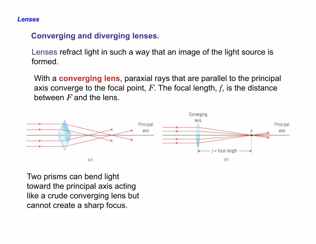
With a converging lens, paraxial rays that are parallel to the principal axis converge to the focal point, F. The focal length, f, is the distance between F and the lens.
Two prisms can bend light toward the principal axis acting like a crude converging lens but cannot create a sharp focus.
Converging and diverging lenses.
Lenses
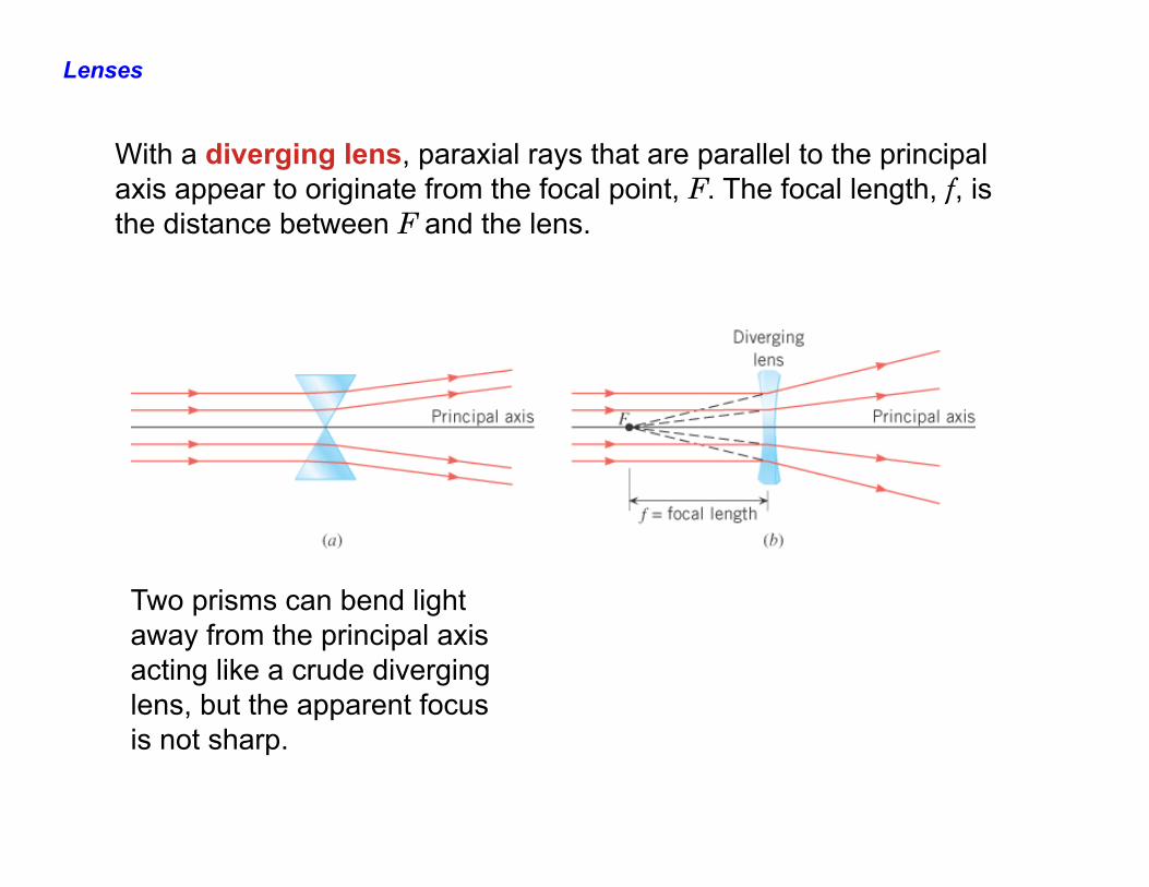
With a diverging lens, paraxial rays that are parallel to the principal axis appear to originate from the focal point, F. The focal length, f, is the distance between F and the lens.
Two prisms can bend light away from the principal axis acting like a crude diverging lens, but the apparent focus is not sharp.
Lenses
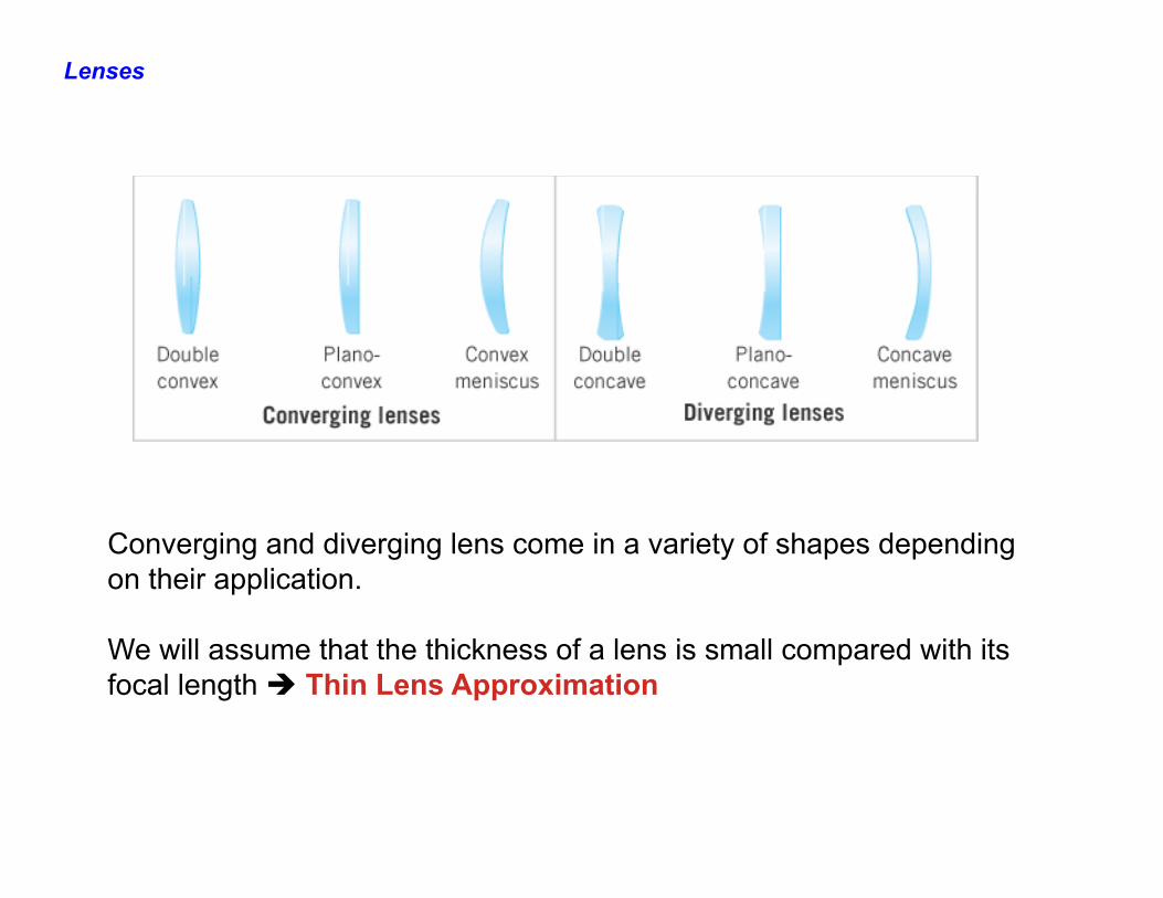
Converging and diverging lens come in a variety of shapes depending on their application. We will assume that the thickness of a lens is small compared with its focal length è Thin Lens Approximation
The Formation of Images by Lenses
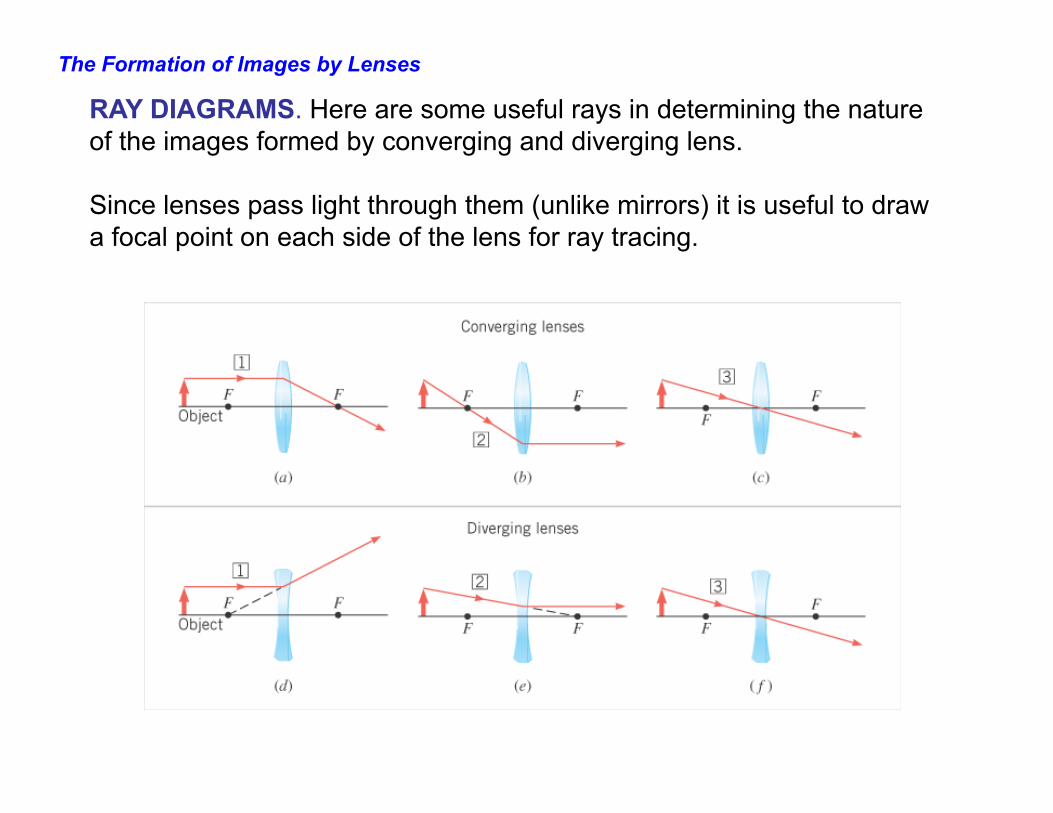
RAY DIAGRAMS. Here are some useful rays in determining the nature of the images formed by converging and diverging lens. Since lenses pass light through them (unlike mirrors) it is useful to draw a focal point on each side of the lens for ray tracing.
The Formation of Images by Lenses
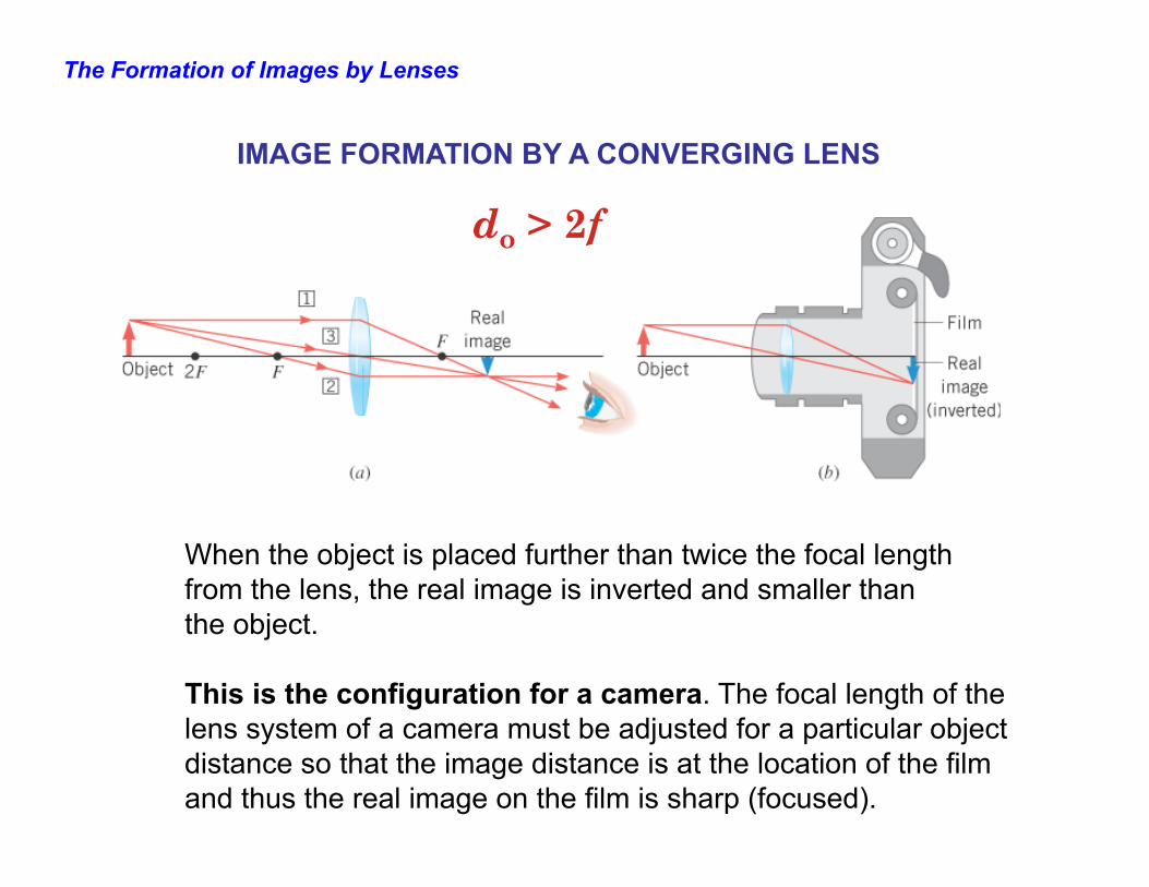
IMAGE FORMATION BY A CONVERGING LENS
When the object is placed further than twice the focal length from the lens, the real image is inverted and smaller than the object. This is the configuration for a camera. The focal length of the lens system of a camera must be adjusted for a particular object distance so that the image distance is at the location of the film and thus the real image on the film is sharp (focused).
do > 2f
The Formation of Images by Lenses
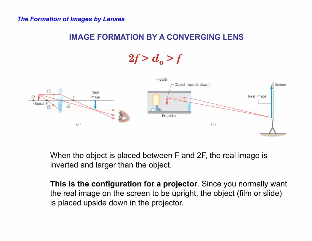
When the object is placed between F and 2F, the real image is inverted and larger than the object. This is the configuration for a projector. Since you normally want the real image on the screen to be upright, the object (film or slide) is placed upside down in the projector.
2f > do > f
IMAGE FORMATION BY A CONVERGING LENS
The Formation of Images by Lenses
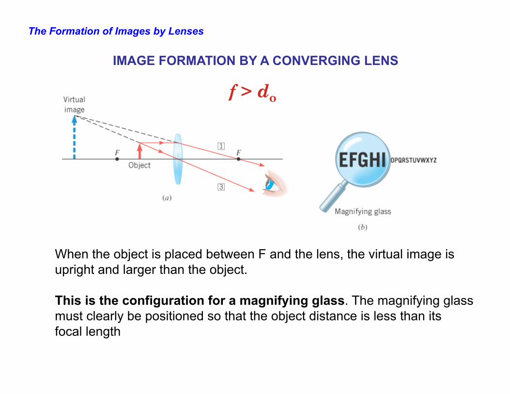
When the object is placed between F and the lens, the virtual image is upright and larger than the object. This is the configuration for a magnifying glass. The magnifying glass must clearly be positioned so that the object distance is less than its focal length
f > do
IMAGE FORMATION BY A CONVERGING LENS
The Formation of Images by Lenses
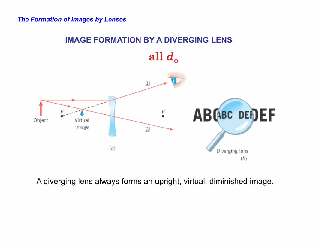
IMAGE FORMATION BY A DIVERGING LENS
A diverging lens always forms an upright, virtual, diminished image.
all do
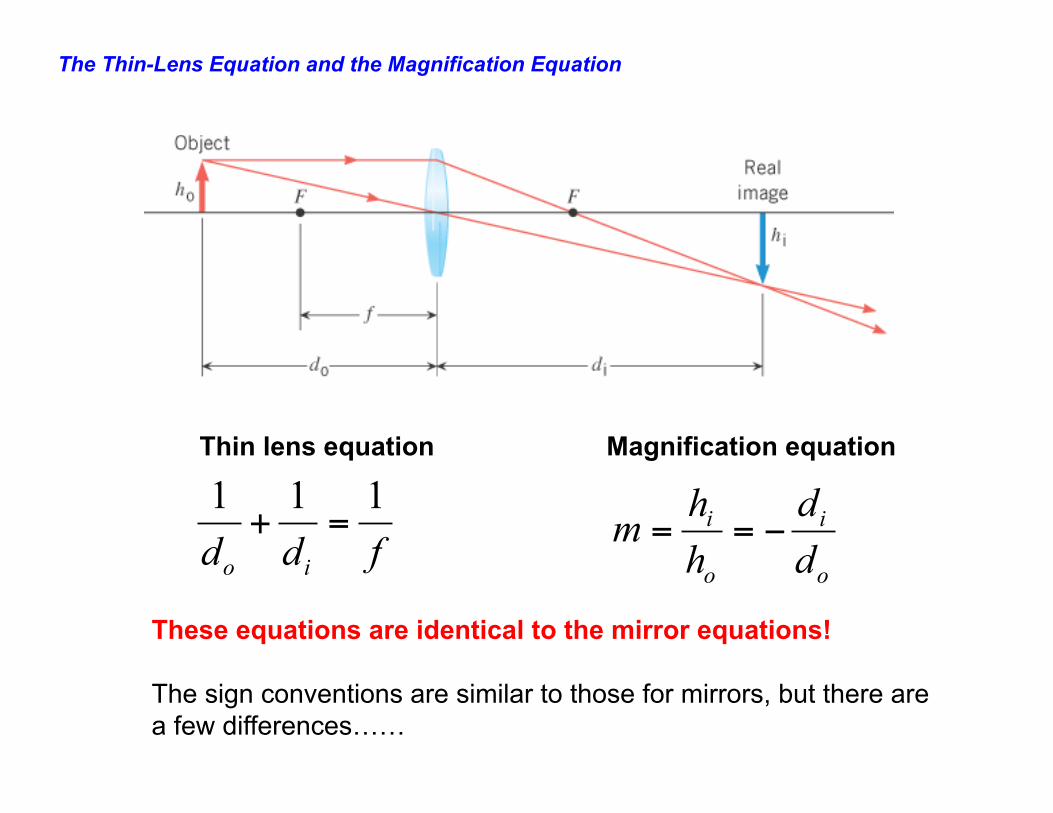
The Thin-Lens Equation and the Magnification Equation
fdd io
111=+
o
i
o
i
dd
hh
m −==
Thin lens equation Magnification equation
These equations are identical to the mirror equations! The sign conventions are similar to those for mirrors, but there are a few differences……
The Thin-Lens Equation and the Magnification Equation
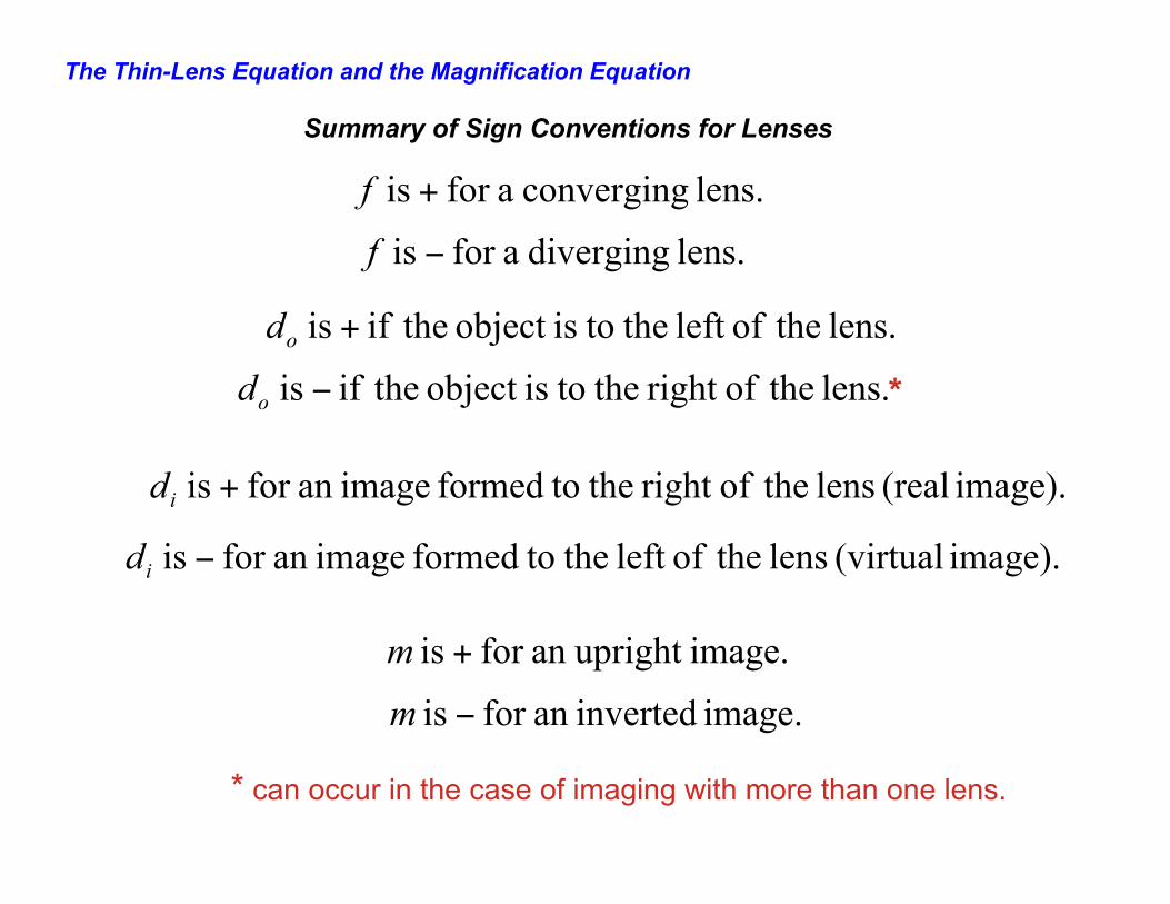
Summary of Sign Conventions for Lenses
lens. converging afor is +f
lens. diverging afor is −f
lens. theofleft the toisobject theif is +od
lens. theofright the toisobject theif is −od
image). (real lens theofright the toformed imagean for is +id
image). (virtual lens theofleft the toformed imagean for is −id
image.upright an for is +m
image. invertedan for is −m
*
* can occur in the case of imaging with more than one lens.
The Thin-Lens Equation and the Magnification Equation
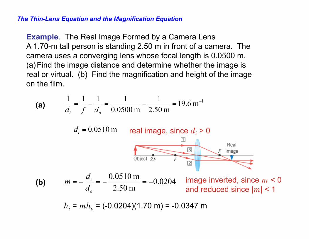
Example. The Real Image Formed by a Camera Lens A 1.70-m tall person is standing 2.50 m in front of a camera. The camera uses a converging lens whose focal length is 0.0500 m. (a) Find the image distance and determine whether the image is real or virtual. (b) Find the magnification and height of the image on the film.
1m 6.19m 50.2
1m 0500.0
1111 −=−=−=oi dfd(a)
m 0510.0=id real image, since di > 0
(b) 0204.0m 50.2m 0510.0
−=−=−=o
i
dd
m image inverted, since m < 0 and reduced since |m| < 1
hi = mho = (-0.0204)(1.70 m) = -0.0347 m
The Thin-Lens Equation and the Magnification Equation
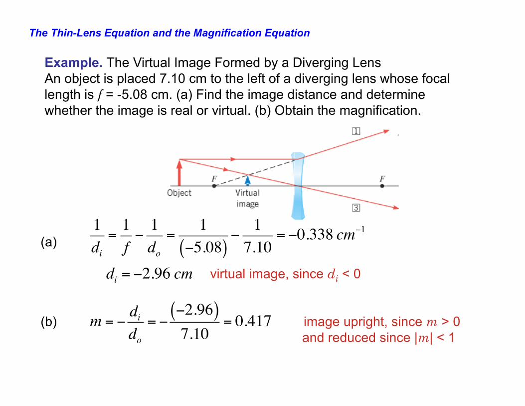
Example. The Virtual Image Formed by a Diverging Lens An object is placed 7.10 cm to the left of a diverging lens whose focal length is f = -5.08 cm. (a) Find the image distance and determine whether the image is real or virtual. (b) Obtain the magnification.
(a) virtual image, since di < 0 (b) image upright, since m > 0 and reduced since |m| < 1
1di=1f−1do=
1−5.08( )
−17.10
= −0.338 cm−1
di = −2.96 cm
m = −dido= −
−2.96( )7.10
= 0.417
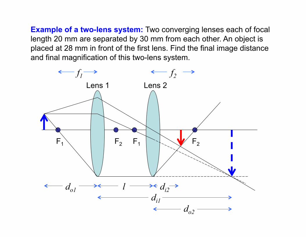
Example of a two-lens system: Two converging lenses each of focal length 20 mm are separated by 30 mm from each other. An object is placed at 28 mm in front of the first lens. Find the final image distance and final magnification of this two-lens system.
Lens 1 Lens 2
F1 F2 F1 F2
do1 l di2 di1 do2
f1 f2
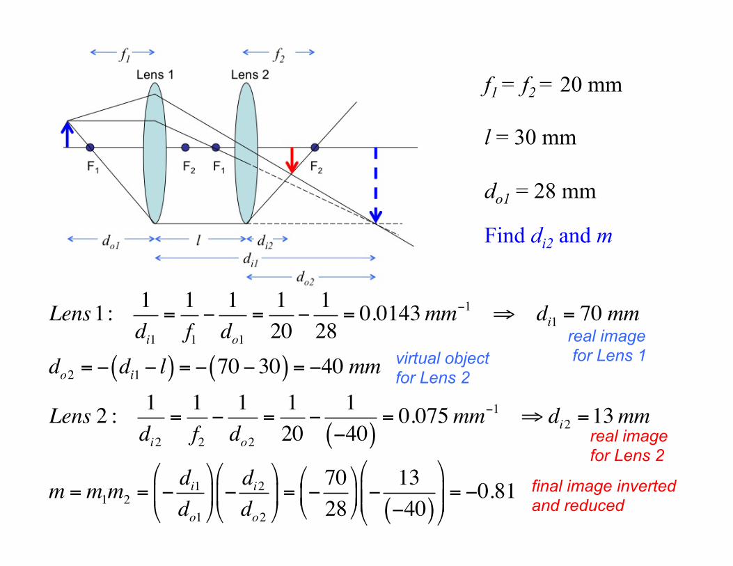
f1 = f2 = 20 mm l = 30 mm do1 = 28 mm Find di2 and m
Lens1: 1di1
=1f1−1do1
=120
−128
= 0.0143mm−1 ⇒ di1 = 70 mm
do2 = − di1 − l( ) = − 70−30( ) = −40 mm
Lens 2 : 1di2
=1f2−1do2
=120
−1−40( )
= 0.075mm−1 ⇒ di2 =13mm
m =m1m2 = −di1do1
#
$%
&
'( −
di2do2
#
$%
&
'(= −
7028
#
$%
&
'( −
13−40( )
#
$%%
&
'((= −0.81
real image for Lens 1 virtual object
for Lens 2
real image for Lens 2
final image inverted and reduced
Chapter 24
Interference and the Wave Nature of Light
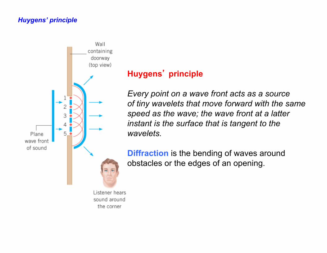
Huygens’ principle
Huygens’ principle Every point on a wave front acts as a source of tiny wavelets that move forward with the same speed as the wave; the wave front at a latter instant is the surface that is tangent to the wavelets. Diffraction is the bending of waves around obstacles or the edges of an opening.
Huygens’ principle
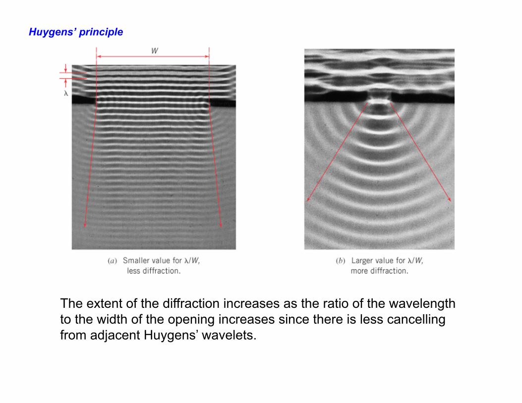
The extent of the diffraction increases as the ratio of the wavelength to the width of the opening increases since there is less cancelling from adjacent Huygens’ wavelets.
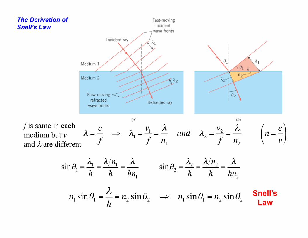
The Derivation of Snell’s Law
sinθ1 =λ1h=λ n1h
=λhn1
sinθ2 =λ2h=λ n2h
=λhn2
n1 sinθ1 =λh= n2 sinθ2 ⇒ n1 sinθ1 = n2 sinθ2
λ =cf
⇒ λ1 =v1f=λn1
and λ2 =v2f=λn2
n = cv
"
#$
%
&'
f is same in each medium but v and λ are different
Snell’s Law


