36
The Relative Nature of Low Probability of Detection Radar A Countermeasures Perspective J.B. Lange Defence R&D Canada – Ottawa Technical Memorandum DRDC Ottawa TM 2012-186 December 2012

The Relative Nature of Low Probability of Detection Radar
A Countermeasures Perspective J.B. Lange
Defence R&D Canada – Ottawa
Technical Memorandum DRDC Ottawa TM 2012-186
December 2012

The Relative Nature of Low Probability of Detection RadarA Countermeasures Perspective
Defence R&D Canada – Ottawa

Principal Author
Original signed by J.B.Lange
J.B.Lange
Principal Author
Approved by
Original signed by J.F.Rivest
J.F.Rivest
H/REW
Approved for release by
Original signed by C.McMillan
C.McMillan
H/DRP
© Her Majesty the Queen in Right of Canada, as represented by the Minister of National Defence, 2012
© Sa Majesté la Reine (en droit du Canada), telle que représentée par le ministre de la Défense nationale, 2012
DRDC Ottawa TM 2012-186
Abstract ……..
A prominent trend in current radar development is in Low Probability of Detection (LPD) technology for both military and civilian applications. Based on relative maximum detection ranges versus enemy sensors, LPD radars attempt to establish dominance in the situational awareness domain, primarily through emission control and data processing. Taking an electronic attack rather than an electronic support perspective, this document provides an alternative view to the nature of LPD radar and contains an analysis of fourteen enabling technologies. The concept of an LPD zone is introduced, and considerations for the jamming of LPD radars, however inelegantly, are described.
Résumé ….....
La technologie de faible probabilité de détection (FPD) représente actuellement une tendance forte dans le domaine du développement des radars pour les applications tant civiles que militaires. À partir des distances maximales de détection par rapport aux capteurs ennemis, les radars à FPD tentent de dominer le domaine de la connaissance de la situation principalement grâce au contrôle des émissions et au traitement de données. En utilisant le point de vue de l’attaque électronique plutôt que celui du soutien électronique, le présent document donne une autre vision de la nature du radar à FPD et contient une analyse de quatorze technologies de base. Le concept d’une zone de FPD est introduit; des aspects du brouillage des radars à FPD, même d’une façon inélégante, sont également décrits.

The wail of a blind
raven can still impede no
matter how off-key.

DRDC Ottawa TM 2012-186
Executive Summary
The Relative Nature of Low Probability of Detection Radar: A Countermeasures Perspective
J.B.Lange; DRDC Ottawa TM 2012-186; Defence R&D Canada – Ottawa; December 2012.
Background: A prominent trend in current radar development is in Low Probability of Intercept (LPI) technology for both military and civilian applications. From an electronic attack perspective, radars that use covert signals are better referred to as Low Probability of Detection (LPD) radars whereas LPI involves the detection of signals by secondary platforms. Based on relative maximum detection ranges versus enemy sensors, LPI radars attempt to establish dominance in the situational awareness domain, primarily through emission control and data processing. This leads to the concept of an LPD zone, a region where the radar has LPD status. Since the LPD zone is bounded by the maximum detection ranges of the radar and the jammer, it is important to note that the LPD status of a radar is equally dependent upon the qualities of the receiver (in this case a jammer) as it is upon the qualities of the radar. Claims by manufacturers that a radar is LPD/LPI based on the implementation of certain technologies or waveforms, without the provision of a benchmark, are of little or no value.
Technologies: This document contains as analysis of fourteen LPD enabling technologies. These have been sorted into three groups based on the means of their implementation. The three groupings are hardware (antenna patterns, low noise receivers, parasitic design, radio frequency selection and stealth technology), signal control (dynamic power management, pre-detection processing gain and scan pattern control) and waveform selection (frequency agility, high duty cycles, intra-pulse coding, noise based transmissions, temporal agility and waveform agility). These technologies attempt to impede the electronic attack kill-chain by denying a jammer awareness of both the fact that it is being illuminated and knowledge of the nature of the waveform being used.
Significance: LPD enabling technologies strain jammers in terms of capacity, agility and sensitivity. Some technologies are exclusive in the focus while others have multiple effects. Under different circumstances of reduced knowledge, noise jamming can be more effective than target based techniques. In other cases this is the reverse and sometimes they can be expected to be of equal effectiveness. However, it should be noted that, while it is certainly true that one cannot intelligently jam a radar that is undetected (owing to a lack of waveform and sequencing information), this fact does not preclude the possibility of effectively jamming an undetected sensor through inelegant means.

Sommaire .....
The Relative Nature of Low Probability of Detection Radar: A Countermeasures Perspective
J.B.Lange; DRDC Ottawa TM 2012-186; R & D pour la défense Canada – Ottawa; Décembre 2012.
Introduction : La technologie de faible probabilité d’interception (FPI) représente actuellement une tendance répandue dans le domaine du développement des radars pour les applications tant civiles que militaires. Du point de vue de l’attaque électronique, le terme radar à faible probabilité de détection convient mieux pour désigner les radars utilisant des signaux dissimulés, puisque l’appellation de « faible probabilité d’interception » renvoie plutôt à la détection de signaux par des plateformes secondaires. En fonction des distances relatives maximales de détection par rapport aux capteurs ennemis, les radars à FPI tentent de dominer le domaine de la connaissance de la situation principalement grâce au contrôle des émissions et au traitement de données. Cela mène au concept d’une zone à FPD, une zone où le radar a un statut FPD. Comme la zone de FPD est limitée par les portées maximales de détection du radar et du brouilleur, il est important de remarquer que le statut FPD d’un radar dépend autant des qualités du récepteur (ici, un brouilleur) que de celles du radar. Les allégations d’un fabricant qui affirme qu’un radar a des propriétés de FPI/FPD en raison de l’utilisation de certaines technologies ou formes d’ondes n’ont qu’une valeur faible ou nulle si elles ne s’accompagnent pas de résultats d’évaluations.
Résultats : Le présent document contient une analyse de quatorze technologies de base de la FPD, qui ont été classées selon trois groupes en fonction de leur moyen de mise en oeuvre, soit les moyens matériels (diagrammes d’antennes, récepteurs à faible bruit, conception parasitique, choix de fréquence et furtivité), le contrôle du signal (gestion dynamique de la puissance, gain de traitement de prédétection, commande de la séquence de balayage) et la sélection de la forme d’onde (agilité en fréquence, facteur d’utilisation élevé, codage intra-impulsion, émissions à bruit, agilité temporelle et agilité en forme d’onde). Ces technologies visent à entraver la chaîne de destruction en empêchant le brouilleur de savoir qu’il est illuminé et de connaître la nature de la forme d’onde utilisée.
Portée : Les technologies de base de la FPD exercent des pressions sur les brouilleurs en ce qui a trait à la capacité, l’agilité et la sensibilité. Certaines technologies se concentrent sur un seul point tandis que d’autres ont des effets multiples. Dans différentes circonstances où les connaissances sont réduites, le brouillage par bruit peut être plus efficace que les techniques fondées sur les cibles. Dans d’autres cas, c’est l’inverse qui est vrai, et les deux techniques peuvent parfois avoir une efficacité équivalente. Même s’il est vrai qu’il est impossible de brouiller intelligemment un radar non détecté (en raison de l’absence d’information sur la forme d’onde et la séquence), il importe de noter que cela n’élimine pas la possibilité de brouiller efficacement un radar non détecté par des moyens peu élégants.
DRDC Ottawa TM 2012-186
Table of Contents
Abstract …….. ................................................................................................................................. i Résumé …..... ................................................................................................................................... i Executive Summary ....................................................................................................................... iii Sommaire ....................................................................................................................................... iv Table of Contents ........................................................................................................................... v List of Figures ............................................................................................................................... vi 1....Introduction............................................................................................................................... 1 2....The Mathematics of Detection.................................................................................................. 3 3....The Impact of Enabling Technologies...................................................................................... 8
3.1 Hardware ....................................................................................................................... 8 3.1.1 Antenna Patterns ............................................................................................. 8 3.1.2 Low Noise Receivers ...................................................................................... 8 3.1.3 Parasitic Radars............................................................................................... 9 3.1.4 Radio Frequency Selection ............................................................................. 9 3.1.5 Stealth Technology ....................................................................................... 10
3.2 Signal Control.............................................................................................................. 10 3.2.1 Dynamic Power Management ....................................................................... 10 3.2.2 Pre-Detection Gain........................................................................................ 11 3.2.3 Scan Pattern................................................................................................... 12
3.3 Waveforms .................................................................................................................. 12 3.3.1 Frequency Agility ......................................................................................... 12 3.3.2 High Duty Cycles.......................................................................................... 13 3.3.3 Intra-pulse Coding......................................................................................... 14 3.3.4 Noise Based Transmissions........................................................................... 14 3.3.5 Temporal Agility........................................................................................... 15 3.3.6 Waveform Agility ......................................................................................... 15
4....Discussion............................................................................................................................... 16 4.1 Summary ..................................................................................................................... 16 4.2 Analysis ....................................................................................................................... 17 4.3 Conclusion................................................................................................................... 19
References ..... ............................................................................................................................... 20 Lists of Acronyms, Initialisms & Symbols ................................................................................... 21

List of Figures
Figure 1: The difference between the detection and interception of radar signals. ......................... 1 Figure 2: The propagation of signals during an air-to-air engagement. .......................................... 3 Figure 3: Typical geometry of an LPD radar engaging a target. ..................................................... 5 Figure 4: The LPD status of a radar depends on the qualities of both the radar and the sensor...... 6 Figure 5: Advanced radar receivers can apply pre-detection processing to achieve sub-noise
signal visibility. ............................................................................................................. 7 Figure 6: Advanced radar receivers can apply pre-detection processing to achieve sub-noise
signal visibility. ........................................................................................................... 17
List of Tables
Table 1: LPD effects by enabling technology. .............................................................................. 16

DRDC Ottawa TM 2012-186
1 Introduction
Currently, the dominant trend in radar development is in Low Probability of Intercept (LPI) technology. What was once the exclusive domain of military radars has started to become prevalent in the civilian market, particularly in the area of navigation radars. Pleasure craft are quite mobile and can therefore be expected to operate in dense signal environments with a wide variety of similar radars. As a result, civilian navigation radars have had to leverage the increased computation power of commercial microprocessors to create agile waveforms in order to avoid mutual interference. This has sparked the development of software-defined radars such as the BR24 by Lowrance. Military operators, in contrast, continue to seek the capability to generate situational awareness without betraying the presence of their sensors. This is especially true when facing the threat of anti-radiation missiles.
However, despite the growth in activity in this field, whenever subject matter experts discuss LPI technology, all too often there is a common feeling of what is meant by this term regardless of the absence of an accepted definition. This document shall attempt to address this deficiency, albeit from an Electronic Attack (EA) perspective rather than from an Electronic Support (ES) point of view, which has been, heretofore, the dominant, if not the exclusive, perspective.
Figure 1 illustrates the difference between these viewpoints for the case of an airborne intercept radar tracking a fighter aircraft in the presence of an Electronic INTelligence (ELINT) surveillance platform that is well separated in angle from the fighter. This is the classic layout used to explain LPI concepts: an ES system being employed to intercept radiation directed against another target. Here, the high sensitivity ES receiver and detection algorithms are used to detect transmissions through their sidelobes which are much weaker signals than those which occur through the mainlobe, which is focussed in another direction.
Figure 1: The difference between the detection and interception of radar signals.
It is worth noting that the terms Low Probability of Intercept and Low Probability of Detection (LPD) are often used interchangeably. Low discriminates between these terms, referring to Interception as “the ability of the ESM system to capture electromagnetic energy due to the antenna being pointed in the correct direction, and the receiver being tuned to the correct frequency” and Detection as “the ability of the ESM system to recognize that energy has in fact been intercepted” [1]. While this demarcation may be appropriate from the ES/ELINT perspective, it shall be argued here that this is too fine for the EA mission. Instead, a more suitable delineation between interception and detection, from a countermeasures perspective, lies with the pointing vector of the main beam of the transmitter.
Consider the primary interaction in Figure 1, that of the interceptor engaging the fighter aircraft. Since the mainlobe of the airborne intercept radar is directed at the fighter, the response of the fighter is based on its ability to detect the incoming signal. Meanwhile, the ELINT aircraft, as an auxiliary player in the scenario, attempts to intercept the transmission, since it is not the intended recipient of the signal. If the radar in Figure 1 uses LPI enabling technology, it would then be referred to as an LPD radar by the targeted aircraft and as an LPI radar by the ELINT aircraft, as indicated in the figure. Consequently, from a countermeasures perspective, whether a radar is deemed to be LPD or LPI depends only upon the direction of the main beam of the radar and the location of the sensor. It is, therefore, independent of the mission of the sensor.
It should be noted that these labels can be dynamic throughout an engagement. If the radar were to alternate the direction of its main beam between the two aircraft, then each aircraft would consider the radar to alternate between an LPD and an LPI radar, depending on which of the two aircraft are illuminated at a given point in time. Examples of how this could happen include the radar being in a search mode, a track-while-scan mode or using an Active Electronically Steered Array (AESA) antenna to track both aircraft on an interleaved basis. Regardless of the terminology used, the achievement of LPD/LPI status by a radar can only be properly determined through computation (specifically an evaluation of detection ranges) and not merely on the use of LPI enabling technologies, much to the chagrin of radar manufacturers.
DRDC Ottawa TM 2012-186
2 The Mathematics of Detection
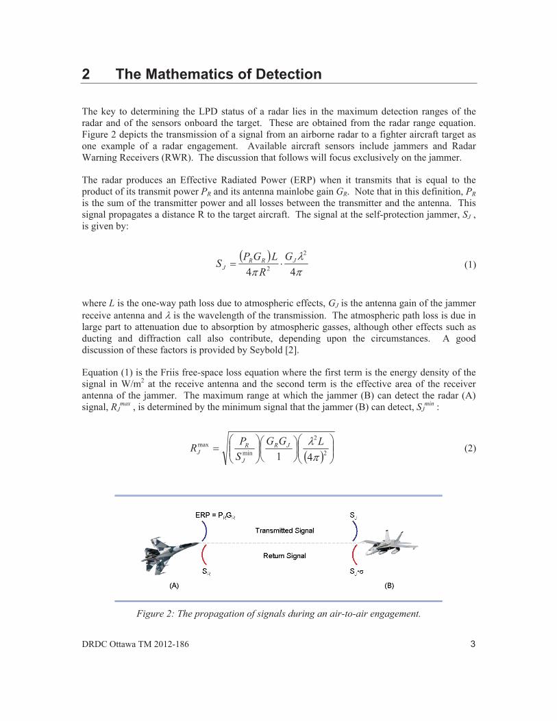
The key to determining the LPD status of a radar lies in the maximum detection ranges of the radar and of the sensors onboard the target. These are obtained from the radar range equation. Figure 2 depicts the transmission of a signal from an airborne radar to a fighter aircraft target as one example of a radar engagement. Available aircraft sensors include jammers and Radar Warning Receivers (RWR). The discussion that follows will focus exclusively on the jammer.
The radar produces an Effective Radiated Power (ERP) when it transmits that is equal to the product of its transmit power PR and its antenna mainlobe gain GR. Note that in this definition, PR is the sum of the transmitter power and all losses between the transmitter and the antenna. This signal propagates a distance R to the target aircraft. The signal at the self-protection jammer, SJ , is given by:
44
2
2JRR
JG
RLGPS (1)
where L is the one-way path loss due to atmospheric effects, GJ is the antenna gain of the jammer receive antenna and is the wavelength of the transmission. The atmospheric path loss is due in large part to attenuation due to absorption by atmospheric gasses, although other effects such as ducting and diffraction call also contribute, depending upon the circumstances. A good discussion of these factors is provided by Seybold [2].
Equation (1) is the Friis free-space loss equation where the first term is the energy density of the signal in W/m2 at the receive antenna and the second term is the effective area of the receiver antenna of the jammer. The maximum range at which the jammer (B) can detect the radar (A) signal, RJ
max , is determined by the minimum signal that the jammer (B) can detect, SJmin :
2
2
minmax
41LGG
SPR JR
J
RJ (2)
Figure 2: The propagation of signals during an air-to-air engagement.
The signal seen by the radar (A), SR , is given by:
444
2
22RRR
RG
RL
RLGPS (3)
where is the Radar Cross-Section (RCS) (i.e. reflection co-efficient) of the target. Equation (3) has a similar structure to equation (2) with the first term giving the strength of the signal as it illuminates the target, the second term reflecting the return path and the third term is the effective area of the receive antenna of the radar, which is assumed to use the same antenna for both transmit and receive functions. The maximum range at which the radar (A) can detect the radar return signal, RR
max , is determined by the minimum signal that the radar (A) can detect, SRmin :
4 3
222
minmax
41LG
SPR R
R
RR (4)
The LPD status of a radar is determined by the ratio of the detection ranges of the radar and jammer:
4 22min
2min
max
max 4
JRR
J
J
R
GPSS
RR
(5)
For the radar to be considered LPD, the ratio in equation (5) must be greater than unity. This condition can be used to evaluate the maximum transmit power that a radar can use against a particular sensor and be stealthy:
22min
2min
,4
JR
JLPDR GS
SP (6)
Substitution of the maximum power value into either equation (2) or (4) gives the maximum LPD range:
4min
min LGG
SSR
J
R
R
JLPD (7)
which is a function of both the ratio of the sensor and radar sensitivities (commonly denoted as in the literature) and the ratio of the receiver gains of the radar and the sensor. This dependence highlights an extremely important fact that is often acknowledged but commonly ignored:

DRDC Ottawa TM 2012-186
Figure 3: Typical geometry of an LPD radar engaging a target.
The LPD status of a radar depends equally upon the qualities of the sensor as is does on the qualities of the radar.
Figure 3 depicts the common conception of target engagement by an LPD radar. The gold region (shown with range rings) denotes the detection zone for the radar, while the blue area is the detection zone for the aircraft jammer. In this case, despite having the advantage of a 1/R2 dependence compared to the 1/R4 dependence of the radar, since the jammer detection range is less than that of the radar, the radar is considered to be LPD.
Figure 4 provides two alternative scenarios for consideration. In the first (leftmost) situation, the same jammer that is depicted in Figure 3 is tracked by a different, less powerful radar than the one shown in Figure 3. In this case, the jammer is able to detect the radar signal before the radar can detect the target; therefore, LPD status is never achieved. However, this same inferior radar can be considered as an LPD system when engaging an even weaker jammer, as illustrated in the second (rightmost) situation.
These figures also illustrate an important subtlety of LPD radar: the concept of an LPD zone. This is the region in the detection zone of the radar between the maximum detection ranges of the radar and the jammer. Whenever a target lies within this zone, the radar will be able to track the target, unbeknownst to the target. However, once the target closes to within its maximum detection range, it will become aware of radar signal and LPD status will be lost.

Figure 4: The LPD status of a radar depends on the qualities of both the radar and the sensor.
A final factor that needs to be examined is the concept of Minimum Detectable Signal (MDS) in a receiver. This is the smallest signal level above noise level at which the receiver can discern an emanation. Receiver noise originates from two sources: the ambient temperature of the device, T0, and the quality of the components within the receiver. The thermal noise level is given by:
BTkN BT 0 (8)
where kB is Boltzman’s constant (1.38 x 10⁻²³ J/K) and B is the bandwidth of the receiver.
The components within the receiver also add noise to the signal path. This added noise is often expressed in terms of an equivalent temperature, Te , where:
BTkN eBC (9)
It is common to combine equations (8) and (9) through the use of a term called the noise figure, F, where [3]:
01 TTF e (10)
In order to be observed, a signal must cross the visibility threshold of the receiver, which is at some minimum Signal-to-Noise Ratio (SNR) above the total noise of the receiver. For a jammer, the MDS can therefore be expressed as:
minJ
SNRFBTkMDS JJJBJ (11)
DRDC Ottawa TM 2012-186
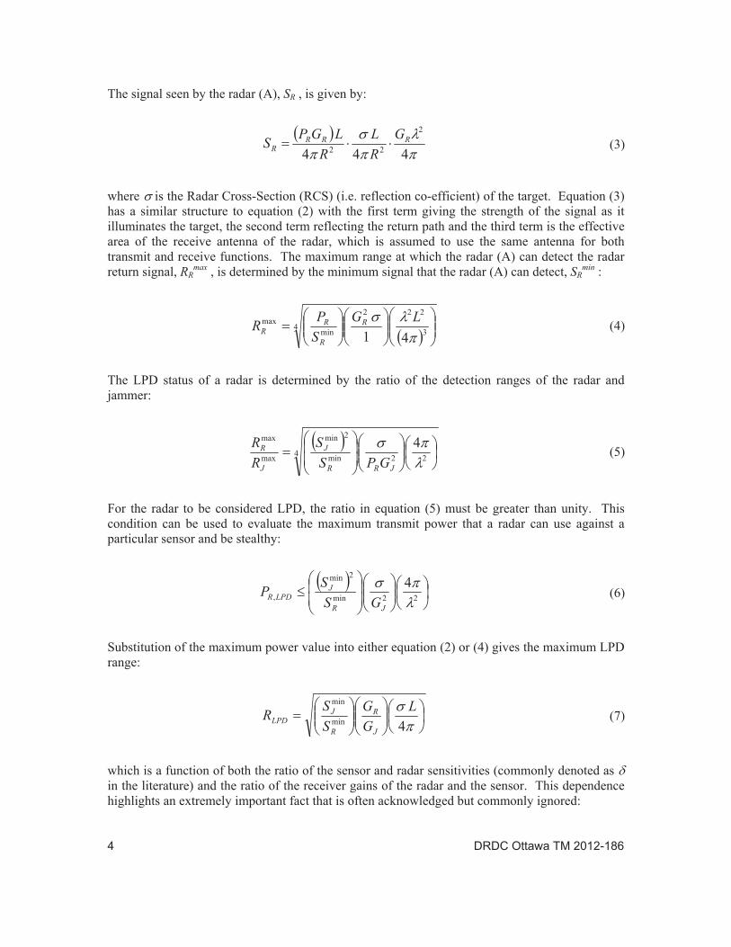
Figure 5: Advanced radar receivers can apply pre-detection processing to achieve sub-noise signal visibility.
In the case of a radar, equation (11) does not necessarily hold, as illustrated in Figure 5. Unlike RWR, ELINT and ES receivers, radar receivers are tuned to specific signal types. As they are optimized to respond to a specific waveform, advanced radars can use pre-detection processing such as pulse compression and non-coherent integration to provide a further processing gain, GP , that is not available to other sensors. This allows radars which use this type of processing to detect incoming signals that are weaker than the thermal noise level, so long as the processing gain is sufficient to bring them above the visibility threshold. That is:
PR
oRRRBR
GSSNRFBTkMDS
min
min
(12)
Of course, for radars which to do not implement pre-detection processing gain:
minRR SMDS (13)
and equation (11) holds.
Now, it should be noted that the preceding discussion is relevant for benign operating conditions. That is, for an emitter and a receiver functioning in isolation from other signals. If other emitters are present, their impact will be felt it one of two ways. The first way is to raise the signal level within the relevant frequency band. As these are extraneous signals, this effect should be considered as a raising of the noise level within the receiver which then impacts both the MDS and Smin values for both the radar and the jammer. The second way is for the extraneous signals to interfere with the jammer’s ability to properly identify the radar. This effect is discussed in section 3.3.6.
3 The Impact of Enabling Technologies
There are a wide variety of LPD enabling technologies available to radar designs [4]. This section examines fourteen of them and outlines any impact on countermeasures. They are generally independent of each other and can be used in isolation or in various combinations to achieve particular desired effects. In terms of function, they have been organized here along three generalized means of implementation: hardware, signal control and waveform.
3.1 Hardware
The following five technologies are all dependent on hardware components. As a result, they are generally beyond the control of radar operators. Their impact is felt in two ways: emission control and data processing.
3.1.1 Antenna Patterns
Antenna pattern development has been focussed mainly on the reduction of sidelobe levels. As the energy field of the antenna is increasingly concentrated into the mainlobe of the pattern, the sidelobe levels are reduced. This is the desired effect since, not only does this suppress the signal levels available to be intercepted by extraneous sensors, it also reduces the susceptibility of the radar to jamming through its sidelobes. Furthermore, jammers that use sidelobes to cue their transmissions will suffer degraded effectiveness.
The augmentation of the mainlobe will either result in a higher antenna gain, GR , with a narrower beam width, or in a lower antenna gain with a wider beam width (in the case of tapering). Broader beam widths reduce the angular precision of the radar, unless other technologies such as monopulse processing are brought to bear. A reduction in angular precision will therefore make the radar more susceptible to angle jamming techniques. Scanning radars with wider beam widths will illuminate targets for greater periods of time (for a fixed scan rate) making them more prone to jamming as there is more time available to the jammer to achieve its intended effects.
Increased antenna gain, on the other hand, results in a higher ERP which enhances the detection range of the radar. While the value of GR has no direct impact on the ability of the radar to achieve LPD status (note the lack of dependence on GR in equation (5)), increased values will push the LPD zone out to greater distances according to equation (7). However, should a designer intend a radar to detect targets out to a certain fixed range, this can then be achieved with a lower PR value, which increases the depth of the LPD zone through equation (5). This in turn may require jammers to be more sensitive in order to detect radars operating at lower power levels.
3.1.2 Low Noise Receivers
The noise level in a receiver directly affects the minimum signal level that the receiver can detect. It can be reduced either by lowering the operating temperature of the receiver through active cooling, narrowing the bandwidth of the receiver or reducing the noise figure of the receiver by

DRDC Ottawa TM 2012-186
using high quality solid state components. Of these three options, only the narrowing of the bandwidth has follow on repercussions (see Section 3.3.2). For a fixed SNR, lowering the noise floor reduces the MDS of the receiver which in turn extends the detection range and LPD zone. A reduction in SR
min also allows for an increase in PR,LPD if desired (see equation (6)) thus further extending the detection range.
The extension in LPD zone need not be outward from the radar if target detection is desired only out to a specific distance. In such a case, the radar is designed around a relative rather than a fixed response to a known target. For example, consider the case where, using a normal receiver, a target of a specific target at a particular calibration distance results in a power value that is 10 dBc above the noise floor. If the receiver noise were to be reduced by 7 dB, then the target signal would still give the same absolute response but would be 17 dB above the noise floor. The transmit power PR could then be reduced by 7 dB, provide the same relative response as the standard noisy receiver, and draw the LPD zone closer to the radar. This technology has no impact on jamming technique selection.
3.1.3 Parasitic Radars
Parasitic radars (which include bi-static and tripwire systems) use the emissions of non-associated transmitters such as radio and television broadcasts to detect and track targets [5]. A detailed analysis of such systems is beyond the scope of this document. However, it can be noted that, while it is relatively easy for an aircraft to detect the illuminating signals, it is very difficult to know which ones are being used at any given time or to locate the position of the receiver. This forces a jammer to use more robust/less system specific techniques such as noise on an ongoing basis to provide aircraft protection. This type of jamming is not desirable as it can be tracked by other passive systems through Home-On-Jam or Track-On-Jam modes. Furthermore, since the location of the detector cannot be determined, jammers must use wide aperture antennas. The resulting reduction in antenna gain will therefore have to be made up by an increase in jammer transmitter power. The use of wide aperture antennas by self-protection or escort jammers also raises the possibility of unintentionally beaconing to other detectors. This is not a concern for stand-off jammers.
3.1.4 Radio Frequency Selection
The choice of carrier frequency is driven by the mission of the radar. For example, long range search radars commonly operate in S-band and target tracking radars tend to operate in X-band. With this understanding of radar parameters, ES sensors such as RWRs focus on these narrow bands to look for signals. They do this to reduce their receiver bandwidths in order to augment their MDS values (see equation (11)) and to reduce the size of their search patterns in frequency space. Radars which break away from these traditional operating bands enjoy a level of LPD status until ES systems adapt to them. Examples of this trend are the APG-76 which operates in the Ku-band [6] and the millimetre wave band, where the population of radars is growing faster than the number of receivers that are able to see this band. Another interesting example is the P-18 search radar which operates in the VHF band that was developed in the 1960’s. This legacy radar system has found new life with many commercial upgrade packages available, thus reviving radar activity in a band that had been relegated to communications in the intervening years [7]. In order to be effective, a jammer must be able to observe the RF spectrum in more bands. This

will either increase the complexity of the jammer control software as it must process an increased parameter space or require the use of multiple systems to cover different bands.
3.1.5 Stealth Technology
Stealth technology is typically not included in discussions of LPD enabling technology since it is a response to rather than a contributor to increased radar capability. However, it is worth including here as RCS directly affects the detection range of a radar. The maximum power value that a radar can use and achieve LPD status varies linearly with RCS as shown by equation (6). Thus, the effect on the radar performance is doubled since both PR and are reduced, lowering, in turn, the target signal received by the radar (see equation (3)). As a result, the depth of the LPD zone is reduced and brought closer to the radar, thereby reducing its performance. The only impact of this technology on EA is a greater control over emissions in order to avoid beaconing and thus alerting a radar to the presence of the aircraft.
3.2 Signal Control
The following three technologies are all hardware based. Their performances are dynamic throughout an engagement and are usually under the control of the radar processor rather than the operators. Their impact is felt in two ways: emission control and data processing.
3.2.1 Dynamic Power Management
This technology allows the radar to optimize its transmitted power PR as an engagement evolves. The two most common control metrics are RCS and range. If the radar uses an RCS metric, it will adjust its emission level based on an initial estimate of the size of the target so as to produce a consistent signal level across all target types. For example, consider the engagements of a fighter aircraft and of a tactical airlift platform. If the radar must transmit with a power of PR' in order to achieve a return signal of SR' when engaging the fighter aircraft, it need only transmit a signal of PR'' in order to receive the same signal level when tracking the tactical airlift platform where:
airlift
fighterRR PP (14)
From a countermeasures perspective, this type of power management is not significant since an onboard jammer will react to whatever signal level it detects. The adaptation of transmit power to RCS is more relevant to the prevention of signal interception by third parties.
Radars that use a range metric continually adjust their transmit power to maintain a constant receive power as the target range changes:
DRDC Ottawa TM 2012-186
2
34 4
LGSRP
R
RR (15)
The purpose of this technology is to place the target within an LPD zone and to move the position of the zone with the target so as to prevent the target from knowing that it is being tracked. This implementation has two other repercussions for countermeasures deployment. The first is as a means to identify (and thus possibly filter out) jamming signals. This is possible for constant power jammers which emit a fixed signal level (usually at maximum power) regardless of the input power they receive since jamming signals originating from these types of jammers will fluctuate in power relative to the RCS of the target. Constant gain jammers are not so affected. The second effect on jamming is indirect. By using ever decreasing power levels as the target range closes to zero, the radar will appear to be at a constant distance from the target. This perception could cause the sensors onboard the target to mistakenly conclude that the threat level posed by the radar is lower than what is in fact the case and therefore suppress the jamming response altogether.
3.2.2 Pre-Detection Gain
Pre-detection gain governs the relationship between the MDS of a receiver and Smin. Processing signals prior to the detection process enables a receiver to see signals that are below the noise floor of the receiver. This sub-noise visibility is conceptually similar to the sub-clutter visibility mechanisms that are used to extract target signals out of the presence of strong clutter. As an added processing stage within the radar, this provides a jammer with an avenue of attack that is desirable as it falls before most electronic protection measure mechanisms within the data stream of the radar.
The two most common forms of pre-detection processing are pulse compression and integration. Pulse compression is based a coded signal superimposed onto the transmitted pulse and is therefore discussed in Section 3.3.3. Pre-detection integration is also referred to as non-coherent integration. It is not as effective as conventional post-detection integration with respective integration factors of n and n where n is the number of pulses being integrated. The advantage of pre-detection processing is muted somewhat by the fact that, in order for a target signal to integrate effectively, it must fall in the same position in the data stream for several Pulse Repetition Intervals (PRIs). This requires short term stability in the waveform used by the radar which can be advantageous to a jammer. This is discussed further in Section 3.3.6.
The application of pre-detection gain is largely impractical for jammer systems. The use of matched filters to detect specific waveforms is conceptually easy to implement. However, this would restrict the jammer to sensitivity towards a specific threat and possibly only to a single mode of that threat. The effectiveness of the matched filter is a jammer depends also on the accuracy with which it is programmed and the sensitivity response roll-off of the filter. The use of waveform agility (see Section 3.3.6) would largely negate any advantage provided by a particular matched filter, and multiple matched filters would have to be employed concurrently. The complexity of such a scheme has prevented this approach from being employed even by RWRs, much less jammers, at the time of writing.
Likewise, non-coherent pulse integration is also not suitable for jammer applications. This is due to the fact that if the jammer cannot detect the signal in the first place, it is quite difficult to integrate signals origination from an unknown location. Once detected, integration provides no benefit to the jammer owing to the fact the (a) it already has sufficient information to enable technique selection and implementation, and (b) it is generally undesirable to delay the onset of jammer.
3.2.3 Scan Pattern
The advent of AESA antennas has provided radars a quantum leap forward in their ability to direct their transmission. Scan patterns are no longer required to follow predictable raster scan patterns that are characteristic of older mechanically scanned antennas. This makes the onset of illumination by a radar difficult to predict. For reactive jamming, this is not an issue since jamming only occurs in response to the arrival of a radar pulse, and if there is no such signal, there is no need to jam. In the worse case scenario (from an EA perspective) pseudo-random target illumination patterns would prevent a jammer from dependably predicting the arrival of subsequent pulses. This would therefore impair the ability of the jammer to produce up-range targets. In such a case, the performance of Digital Radio Frequency Memory-based jammers would degrade to those which use Frequency Memory Loop technology. This effect is less significant when the radar transmits an entire sequence of pulses with each illumination for integration purposes. Similarly, if the jammer mission involves pre-emptive jamming, the lack of predictability in the onset of illumination can restrict a jammer to noise techniques, which, as mentioned previously, can be prone to triggering home-on-jam or track-on-jam modes.
3.3 Waveforms
The following six technologies are combined implementations of hardware and software. They are dynamic in character and can be controlled either by the operator or by the radar itself. While each requires a certain level of augmented signal processing, their effects are mainly felt through emission control.
3.3.1 Frequency Agility
Modern radars have the ability to transmit on numerous frequencies within their operational bandwidth. This provides the radar an advantage over jammers since the radar knows its hopping pattern and will tune its receiver to the proper frequency for each transmission whereas the jammer must search for each new signal. The use of frequency agility comes at a cost of loss of coherence between target returns when two different frequencies are used. Radars mitigate this consequence by changing frequency after a number of consecutive pulses, referred to as a coherent processing interval. Jammers have three options to mitigate the use of frequency agility: (i) have an instantaneous bandwidth larger than the operational bandwidth of the radar, (ii) use predictive technology, and (iii) take a spread spectrum approach to jamming.
In the case of the first option, all of the available radar frequencies will fall within a single frequency window of the jammer receiver. The jammer will then detect any frequency used and will not have to dedicate resources to searching for the signal. This comes at a cost of having a

DRDC Ottawa TM 2012-186
receiver noise level that is higher than for the radar since BJ > BR. This affects the relative MDS levels and therefore the maximum detection range of the jammer relative to that of the radar. A further subtlety to this option is in the accuracy of Doppler modulation. Unless the jammer measures the actual frequency being used, the Doppler modulations applied to its jamming waveforms can be off by as much as half of its instantaneous bandwidth which can, in certain circumstances, be large enough to negate their effects.
The second option requires the use of a dedicated CPU that keeps track of the frequency history of the radar and attempts to forecast its future performance. Such technology was first developed in the field of pulse repetition interval prediction [8] and is readily adaptable to the frequency agility problem. The weakness of this solution, however, is that frequency agility is less predictive. This is because radars will use different PRI values in specific combinations to mitigate ranging effects such as ghosting or multipath [9]. Not only is the choice of frequency independent of such considerations, but also many advanced radars will actively survey the environment to select the clearest frequencies for subsequent use, adding a randomness that is unique to each engagement. Regardless of the method used, a general problem for digital jammers is that of technique reset due to architecture design. When a jammer detects a signal at a new frequency, it is a common architecture design to consider this as a new signal. This will cause the jammer to reset its jamming clock to zero. Therefore, if the rate at which the radar changes frequency is greater than the duration of the jamming technique, the jammer will never complete the technique, thus mitigating its effects. Of course, this is not a factor for noise based techniques such as cover pulses.
3.3.2 High Duty Cycles
When a radar detects a target return, it measures the energy contained within that signal. The more energy contained within the signal, the greater the chance that it will be detected. There are two ways to increase the energy within a radar pulse. The first is to increase the power level for a fixed pulse width, but this compresses the size of the LPD zone (see equation (5)). The second way is to lengthen the pulse width for a given value of PR. This is the preferred method for LPD radar. Not only does this allow for small transmit powers to be used, but given the reciprocal nature of pulse width and band width, the use of long pulses results in a narrowing of the radar bandwidth which has the additional effect of reducing the noise level within the receiver (see equation (8) and Section 3.1.2).
Radars which use long pulse durations have large duty cycles (up to and including continuous wave transmission). Such signals have very good Doppler sensitivity but generate poor range information. In systems where range information is required, modulations such as frequency-induced-ranging must be employed. Therefore, effective jamming ought to be frequency based. As a result, while noise jamming might be effective, the effectiveness of extended cover pulses can be expected to be limited.
The effectiveness of repeater based jammers is partially dependant upon the ability of the jammer to record an entire pulse. Insufficient capacity within a jammer entails that long pulses might be clipped, thus degrading the quality of the subsequent jamming signals. Furthermore, unless dual-port memory is used, jamming cannot occur until recording has completed. This prevents jamming signals from being placed near the skin return of the aircraft being protected if pulse
compression is used. The closest spacing would be equal to the sum of the uncompressed pulse width and the throughput delay of the jammer.
3.3.3 Intra-pulse Coding
Along with non-coherent integration, pulse compression through the application of intra-pulse coding are the two most common means of achieving pre-detection processing gain for a radar. Coding can be applied in either analog or digital means. Analog coding involves a continual change in frequency across the pulse. Referred to as a “chirp”, these shifts can be either linear or non-linear and with either an increase or decrease in frequency. Digital coding involves phase modulation of the signal. There are a number of different codes including the binary Barker codes and the multi-phase Frank codes. These can be used either on their own or as the basis of compound codes with lengths in excess of 200 bits being reported in the open literature [10]. The basic Barker codes provide up to 11.1 dB of compression gain, GP, with compound codes generating even higher levels of signal augmentation.
Complex codes can also be produced by the concatenation of independent sub-pulses into on large transmitted pulse. When such structures are employed, each sub-pulse is used by the radar to derive different information such as Doppler shift and range. This means that jammers may have to apply different modulations to the different sub-pulses in order to achieve desired effects. This may be problematic for single channel jammers but provides new opportunities for multiple channel jammers.
Unlike integration, intra-pulse coding provides a means to discriminate against extraneous signals that are mismatched with the compression filters of a radar. While this may be of meaningful benefit against noise based jamming, it also provides a significant advantage to repeater types jammers. By basing their waveforms on direct copies of the transmitted pulses, repeater-based jammers can produce signals which the victim radar is pre-disposed to accept, and consequently avoid the inherent rejection of mismatched signals to which transponder and noise-based jammers are liable.
3.3.4 Noise Based Transmissions
Radars which use noise based waveforms transmit aperiodic signals that are as spectrally similar to white noise as possible. Their noise-like signals are typically spread evenly across their entire frequency bandwidth and, due to their random transmission scheduling, there are not easily detected by standard spectral analysis methods. Since each pulse is unique, standard pulse compression techniques will not work. Instead, the radar must retain a copy of each pulse for correlation tests against each returned signal.
Noise based waveforms can be thought of as ultra-long coded pulses composed of very short bit lengths which are unique to each transmitted pulse. From this perspective, the codes are far from optimal in terms of compression gain (a component of GP; see Section 3.3.2) but, given their extreme length, make these radars very sensitive to reflections of their own signals to the exclusion of other signals. This quality enables multiple systems to occupy the same frequency band without mutual interference, subject to power saturation effects. Finally, the ultra-wide bandwidth used by these systems allows for very small range resolutions.
DRDC Ottawa TM 2012-186
Since the source radar must retain a copy of the transmission for later identification, the detection of noise based emissions by a jammer or RWR is very difficult. Once detected, the jammer must have the memory depth and bandwidth to record the pulse sufficiently well in order to be able to suitably replicate the signal. Given the very wide bandwidths and long pulse durations, this can be problematic for most jammers using a digital radio frequency memory. It can therefore be expected that older, frequency memory loop based jammers should provide better performance.
At the time of writing there are no such radars fielded by the world’s militaries. Noise based radars remain an area of ongoing research and, given the current rate of development in data processing capability, they continue to be an enticing possibility for the future.
3.3.5 Temporal Agility
A secondary capability provided by AESA antennas is the capacity to engage multiple targets simultaneously by interleaving different illumination patterns and using a digital form of track-while-scan data processing. The time between illuminations for a particular target can be relatively large, on the order of seconds per transmission, when compared to typical coherent processing intervals which are usually measured in milliseconds. Such large time scales are comparable to the scan rates of long range search radars and are reasonable given the movement of fighter aircraft over these periods (340 m at Mach 1) and the size of a range resolution cell (150 m for a 1 s pulse width). Further complicating matters for a jammer is that each transmission can use a different waveform (see Section 3.3.6) making the ongoing detection of the radar signal problematic.
3.3.6 Waveform Agility
Waveform agility refers to those circumstances when a radar alters more than one parameter such as carrier frequency, PRI and/or pulse width. In the past, waveforms were optimized for different mission roles and agility was limited. This changed with the onset of high powered computing which has enabled the development of multi-mode radars which transmit a variety of signal types. For a jammer, the impact of this technology is in the ability to suitably follow the change in waveform, either through a broadening of signal capacity (e.g. bandwidth) or through predictive technology.
The advent of software defined radar brings this technology to the forefront in terms of availability, spanning all radar classes from advance AESA equipped airborne intercept radars to the common commercially available civilian navigation radars. Research into the Multiple-Input/Multiple-Output (MIMO) concept will further drive the impact of this technology. In what is essentially a data fusion approach to the target tracking problem, topics of interest in the field of MIMO radar include the use of concurrent multi-polarized signals and the integration of multi-static radar systems. The impact on jamming will be even more significant once cognitive radars, which will automatically adapt their waveforms throughout an engagement based on an evolving situational awareness becomes available, likely in the horizon III timeframe (10+ years).

4 Discussion
4.1 Summary
There are a number of LPD enabling technologies available to the modern radar designer, with each attempting to mask the presence of a signal from an adversary. Regardless of the means of implementation, LPD effects fall into the following three basic categories:
Breadth: This refers to the breadth of a sensor to detect the parameters of transmission. Examples include bandwidth and memory depth.
Agility: This expresses the ability of a sensor to follow changes in the transmitted signal.
Strength: This reflects sensitivity of the receiver to the power of the transmitted signal.
Table 1 lists the fourteen radar technologies described in Section 3 and categorizes the LPD enabling technologies associated with each of them.
Table 1: LPD effects by enabling technology.
TECHNOLOGY BREADTH AGILITY STRENGTH
Antenna Patterns X
Low Noise Receivers X
Parasitic Design X
Radio Frequency X Har
dwar
e
Stealth X
Power Management X X
Pre-Detection Gain X
Sign
al C
ontro
l
Scan Pattern X
Frequency Agility X X
High Duty Cycle X X
Intra-Pulse Coding X
Noise Based X X
Temporal Agility X Wav
efor
m S
elec
tion
Waveform Agility X X

DRDC Ottawa TM 2012-186
Figure 6: The EA kill chain.
4.2 Analysis
The effective deployment of countermeasures for the protection of aircraft generally follows the EA kill chain, which is illustrated in Figure 6. Unless they are operating pre-emptively, the first link in the chain for a jammer is to detect the presence of incoming signals. Next, the signal must be identified against a library of threat systems in order to trigger a response. This is done so as to avoid the wasting of resources (energy, expendables, system time, etc.) against systems that are not deemed as threats. The jammer must then track the parameters of the signal (such as direction, frequency, pulse width, etc.), noting any change in the waveform which affect the timing of the jamming signals (i.e. PRI) or that indicate a change in radar function such as the migration from search to track mode. Based on this information, the countermeasure system must select the appropriate response, deploy the response and then pause to asses the impact of the countermeasure.
The development of well matched, effective jamming techniques is specific to each particular radar and is beyond the scope of this document. However, in all cases, it is true that in order to effectively counter a radar, a jammer must know the following information:
1. That it is being illuminated by a threat radar (the why),
2. The parameters on which it is to base its transmissions (the what), and
3. How to time its signals (the when).
The fourteen enabling technologies discussed in this paper attack this EA kill-chain process in different ways as outlined in Table 1 and shown in Figure 6. In the discussion that follows, two types of jamming are considered: noise and targets. Noise jamming includes extended cover pulses (in both range and frequency) as well as modulated noise signals such as swept noise. Target techniques encompass all forms of targeted jamming, such as range gate pull off techniques, velocity gate pull off techniques, and angle jamming techniques which use pulses that are not necessarily derived from the transmitted pulse, such as swept square wave signals, etc. It is acknowledged that the use of the term ‘target’ encompasses a much broader scope of techniques than is common. However, since they all involve specific short duration signals that are targeted against specific aspects of the radar signal processor, the term is valid for this discussion.

The capacity-based technologies (radio frequency selection, frequency agility, high duty cycles, noise based transmissions and waveform agility) all require a jammer to be sensitive to an ever increasing parameter space. This includes having wider instantaneous bandwidths, following signals across multiple bands and the requirement for deeper memory banks. Not only does this reduce the sensitivity of the jammer receiver in the case of bandwidth, but also opens it up to distraction by competing signals. Jammers which attempt to counter radars for which they were not designed to defeat can suffer from poor signal measurements such as clipping or signal digitization that is too coarse to be effective. In some cases, the jammer may not be able to measure the signal at all as would be the case for a receiver with an operational bandwidth of 8-12 GHz trying to detect an APG-76 which is a Ku-band radar. These technologies therefore attack the ‘what’ in the kill-chain, bringing down the quality of the data available to the jammer. The effectiveness of noise and target techniques are expected to be roughly equal as neither will have the required measured parameter precision required to achieve an optimal solution.
The agility-based technologies (dynamic power management, scan pattern, frequency agility, temporal agility and waveform agility) all require a jammer to adapt on an ongoing basis to a signal that evolves as an engagement progresses. Assuming that the radar agility is within the ability of the jammer to detect (else it is a capacity issue), this forces the jammer to have some sort of pattern recognition and prediction capability. With the exception of dynamic power measurement, the usage of parameter agility comes at a cost of signal coherence which only comes into effect when stable signals are used. This performance impairment is often acceptable because of the significant impact on jamming these technologies provide. Since radars know a priori the scheduling and nature of each change, they can process the data associated with each signal, unlike a jammer which must react to the change and search for the new signal. The association of a new waveform to the previous one can be problematic in a dense signal environment and can cause a jammer to restart its technique before it finishes. Since these technologies attack both the ‘what’ and the ‘when’ in the kill-chain, noise techniques should be more effective than target techniques in the absence of accurate waveform data.
The strength-based technologies (antenna patterns, low noise receivers, parasitic design, stealth, dynamic power management, pre-detection gain, high duty cycle, intra-pulse coding and noise based transmissions) are the most prevalent. They attack the ‘why’ in the kill chain as their intent is to prevent the jammer from being aware that it is being illuminated. If the radar signal is below the detection floor of the jammer, there are no parameters for the jammer to use to produce target techniques. Pre-emptive noise jamming, therefore, is the only available option. However, if the signal is detected, target technique performance can in fact be augmented. For example, by exploiting the existence of intra-pulse coding, a jammer can made its signals more attractive to a radar and leverage the advantages of pre-detection processing gain that would not be available to noise techniques.
Of all technologies, parasitic design and stealth are quite unlike the others. Parasitic radar have zero transmissions and are therefore impossible to detect through conventional means. Stealth technology is the only one whose use is to counter radar performance. Despite their unique natures, both are relevant to the consideration of LPD radar engagement.
DRDC Ottawa TM 2012-186
4.3 Conclusion
The use of LPD radars arises out of the ongoing conflict over situational awareness dominance. It is important to keep in mind that radars which use LPD enabling technology and waveforms are marketed as LPI systems based solely on their inclusion. Unless a benchmark detection is identified (eg. ALR-56M at a distance of 20 km), such claims are of little or no value. Only an analysis of maximum detection ranges of the radar and its jammer will clarify whether or not a radar is LPD for a given situation. If it exists, the depth of the LPD zone is also an important consideration.
One of the aims of LPD radars is to prevent jammers from knowing that they are being illuminated. If this cannot be achieved, their secondary goal is to restrict sufficient waveform parameter data from the jammer to prevent the use of effective jamming techniques. It is certainly true that one cannot intelligently jam a radar that is undetected (owing to a lack of waveform and sequencing information). However, this fact does not preclude the possibility of effectively jamming an undetected sensor through inelegant means.

References .....
[1] Low,M. (2011), Detection of LPI radar emissions: A tutorial, (DRDC Ottawa TM 2011-200) Defence R&D Canada – Ottawa.
[2] Seybold,J.S. (2005), Introduction to RF Propagation, Hoboken: John Wiley & Sons, Inc., p.111–133.
[3] Mahafza,B.R. (1998), Introduction to Radar Analysis, Boca Raton: CRC Press LLC, p.61–65.
[4] Pace,P.E. (2009), Detecting and Classifying Low Probability of Intercept Radar, 2nd ed., Norwood: Artech House
[5] Griffiths,H.D. (2010), Passive Bistatic Radar and Waveform Diversity, In WaveformDiversity for Advanced Radar Systems, 3-1–3-22, Ottawa: NATO RTO-EN-SET-119(2010)
[6] Tobin,M.E. (1996), Adaptation of AN/APG-76 multimode radar to the smuggling interdiction mission, In Proceedings of the 1996 IEEE National Radar Conference, 13–18, IEEE
[7] P-18 early-warning radar (online), IHS Jane’s, Inc., https://janes.ihs.com/CustomPages/Janes/DisplayPage.aspx?ShowProductLink=true&DocType=Reference&ItemId=+++1380055&Pubabbrev=JREW (Access date: 15 Aug. 2012)
[8] MC Countermeasures (online), MC Countermeasures, Inc., http://www.mc-cm.ca (Access date: 20 Aug. 2012)
[9] Stimson,G.W. (1998), Introduction to Airborne Radar, 2nd ed., Mendham: SciTech Publishing, Inc., p.156–162.
[10] Yang,J and Sarkar,T.K. (2006), A novel Doppler-tolerant polyphase codes for pulse compression based on hyperbolic frequency modulation, Digital Signal Process, doi:10.1016/j.dsp.2006.09.006

DRDC Ottawa TM 2012-186
Lists of Acronyms, Initialisms & Symbols
AESA Active Electronically Steered Array
EA Electronic Attack
ELINT Electronic Intelligence
ERP Effective Radiated Power
ES Electronic Support
LPD Low Probability of Detection
LPI Low Probability of Interception
MDS Minimum Detectable Signal
MIMO Multiple-Input/Multiple-Output
PRI Pulse Repetition Interval
RWR Radar Warning Receiver
SNR Signal-to-Noise Ratio
B Bandwidth
F Noise Figure
GJ Gain of the jammer receive antenna
GP Pre-detection processing gain
GR Gain of the radar receive antenna
kB Boltzmann’s constant
Wavelength of propagation
L One-way atmospheric path loss
NC Component noise
NT Thermal noise
PR Radar transmit power
PR,LPD Radar transmit power for LPD operation
R Range
RLPD Maximum range for LPD operation
Radar cross-section
SJ Radar signal strength at the jammer location
SR Radar signal strength at the radar location

This page intentionally left blank.

DOCUMENT CONTROL DATA (Security classification of title, body of abstract and indexing annotation must be entered when the overall document is classified)
(The name and address of the organization preparing the document. Organizations for whom the document was prepared, e.g. Centre sponsoring a contractor's report, or tasking agency, are entered in section 8.)
(Overall security classification of the document including special warning terms if applicable.)
(The complete document title as indicated on the title page. Its classification should be indicated by the appropriate abbreviation (S, C or U) in parentheses after the title.)
(last name, followed by initials – ranks, titles, etc. not to be used)
(Month and year of publication of document.)
(Total containing information, including Annexes, Appendices, etc.)
(Total cited in document.)
(The category of the document, e.g. technical report, technical note or memorandum. If appropriate, enter the type of report,
e.g. interim, progress, summary, annual or final. Give the inclusive dates when a specific reporting period is covered.)
(The name of the department project office or laboratory sponsoring the research and development – include address.)
(If appropriate, the applicable research and development project or grant number under which the document was written. Please specify whether project or grant.)
(If appropriate, the applicable number under which the document was written.)
(The official document number by which the document is identified by the originating activity. This number must be unique to this document.)
(Any other numbers which may be assigned this document either by the originator or by the sponsor.)
(Any limitations on further dissemination of the document, other than those imposed by security classification.)
(Any limitation to the bibliographic announcement of this document. This will normally correspond to the Document Availability (11). However, where further distribution (beyond the audience specified in (11) is possible, a wider announcement audience may be selected.))
(A brief and factual summary of the document. It may also appear elsewhere in the body of the document itself. It is highly desirable that the abstract of classified documents be unclassified. Each paragraph of the abstract shall begin with an indication of the security classification of the information in the paragraph (unless the document itself is unclassified) represented as (S), (C), (R), or (U). It is not necessary to include here abstracts in both official languages unless the text is bilingual.)
A prominent trend in current radar development is in Low Probability of Detection (LPD)technology for both military and civilian applications. Based on relative maximum detectionranges versus enemy sensors, LPD radars attempt to establish dominance in the situationalawareness domain, primarily through emission control and data processing. Taking anelectronic attack rather than an electronic support perspective, this document provides analternative view to the nature of LPD radar and contains an analysis of fourteen enablingtechnologies. The concept of an LPD zone is introduced, and considerations for the jamming ofLPD radars, however inelegantly, are described.
La technologie de faible probabilité de détection (FPD) représente actuellement une tendanceforte dans le domaine du développement des radars pour les applications tant civiles quemilitaires. À partir des distances maximales de détection par rapport aux capteurs ennemis, lesradars à FPD tentent de dominer le domaine de la connaissance de la situation principalementgrâce au contrôle des émissions et au traitement de données. En utilisant le point de vue del’attaque électronique plutôt que celui du soutien électronique, le présent document donne uneautre vision de la nature du radar à FPD et contient une analyse de quatorze technologies debase. Le concept d’une zone de FPD est introduit; des aspects du brouillage des radars à FPD,même d’une façon inélégante, sont également décrits.
(Technically meaningful terms or short phrases that characterize a document and could be helpful in cataloguing the document. They should be selected so that no security classification is required. Identifiers, such as equipment model designation, trade name, military project code name, geographic location may also be included. If possible keywords should be selected from a published thesaurus, e.g. Thesaurus of Engineering and Scientific Terms (TEST) and that thesaurus identified. If it is not possible to select indexing terms which are Unclassified, the classification of each should be indicated as with the title.)


![[ENTER CHAPTER TITLE HERE] - cradpdf.drdc …cradpdf.drdc-rddc.gc.ca/PDFS/unc120/p536906_A1b.pdf · To be effective in this pursuit, the Canadian Forces (CF) began a process of ...](https://static.documents.pub/doc/80x56/5b9ab49109d3f20b318c1c0c/enter-chapter-title-here-to-be-effective-in-this-pursuit-the-canadian-forces.jpg)


