Indian Institutions and Fermilab Indian Institutions and Fermilab Indian Institutions and Fermilab Indian Institutions and Fermilab Collaboration: Collaboration: Collaboration: Collaboration: A A A A Road We Travel Together Road We Travel Together Road We Travel Together Road We Travel Together Shekhar Mishra Project-X, International Collaboration Coordinator Fermilab
Transcript
Indian Institutions and Ferm
ilab
Indian Institutions and Ferm
ilab
Indian Institutions and Ferm
ilab
Indian Institutions and Ferm
ilab
Collaboration:
Collaboration:
Collaboration:
Collaboration:
A
A
A
A Road W
e Travel Together
Road W
e Travel Together
Road W
e Travel Together
Road W
e Travel Together
Shekhar Mishra
Project-X,
International Collaboration Coordinator
Fermilab
Thoughts
Thoughts
Thoughts
Thoughts
•Till 2003, Indian Science Program was foreign to me.
–Indian economy was growing very fast. India had established
collaboration in many areas with US (NIH, NASA, IT Industries)
–I made it a mission to extend Indian physics collaboration in US
•It started with my initial role in International Linear Collider
–Today this collaboration with India has taken a magnitude that I
myself had not contemplated
Vision of Nuclear India
Vision of Nuclear India
Vision of Nuclear India
Vision of Nuclear India
“The introduction of atomic energyin
India in the early 1950s was not
purely for the sake of introducing
atomic power, but essentially for the
introduction of new technologies
dependent on basic sciences
generated within” Bhabha to
Ramanna
How did this new effort start ?
How did this new effort start ?
How did this new effort start ?
How did this new effort start ?
•Physicists from Indian Institutions have been collaborating at Ferm
ilab
since 1986.
•In 2002, LHC expected start and ILC were the talk of the town.
•India HEP was thinking of packing its bag from Ferm
ilab and moving to
CERN
–D0 �
CMS
•In Fall of 2002, with the help of Indian scientists collaborating at
Ferm
ilab, I met with Prof. V. S. Ramamurthy, Secretary, Department of
Ferm
ilab, I met with Prof. V. S. Ramamurthy, Secretary, Department of
Science and Technology (NSF) and Dr. Anil Kakodkar. Secretary,
Department of Atomic Energy (DOE).
–Message I got: “Get our scientists excited about the science and show that
there are m
utual benefits to both sides.”
–A working group was form
ed to develop this collaboration
•Since that meeting, We have been to India several times
–First just to talk about Indian program, understand what Indian scientists want
–Understand how we can work together.
–Work with Indian scientists in developing a accelerator R&D program
–Today we have one M
OU and four Addendums in Accelerator and Neutrino
–We are discussing significant “In-Kind” contribution from India for Project-X
Indian DAE
Indian DAE
Indian DAE
Indian DAE
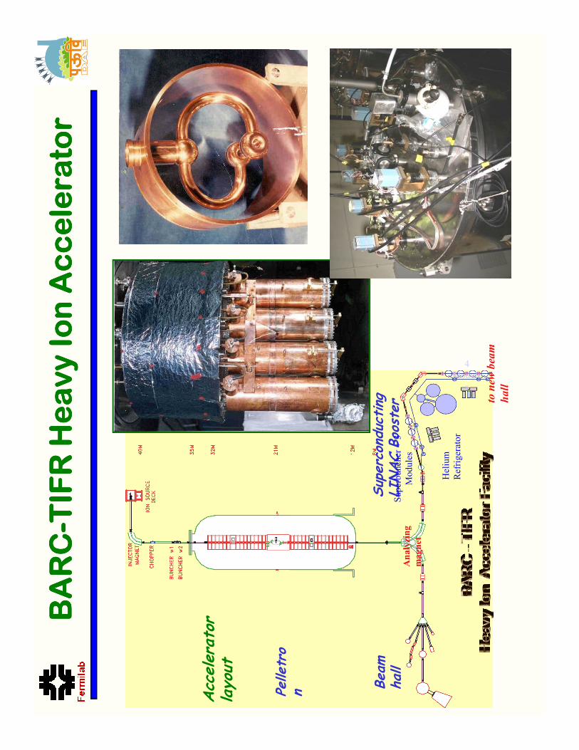
BARC
BARC
BARC
BARC- ---TIFR
TIFR
TIFR
TIFRHeavy Ion Accelerator
Heavy Ion Accelerator
Heavy Ion Accelerator
Heavy Ion Accelerator
Acc
eler
ator
layo
ut
Pelle
tro
n
Sup
erco
nduc
ting
LI
NAC B
ooster
n Bea
m
hall
Helium
Refrigerator
Superbuncher + 3
Modules
4
Module
s
to new beam
hall
Analyzing
magnet
Proton IS
50 keV
RFQ
3 MeV
DTL
20 MeV
DTL/
CCDTL
Super-
conducting
SC
Linac 1 GeV
100 MeV
Norm
al Conducting
High current injector 20 MeV, 30 mA
Design completed and fabrication is in progress
ECR Ion Source
RFQ
DTL
Phase 1
Phase II
Phase III
Accelerator Development for ADS
Accelerator Development for ADS
Accelerator Development for ADS
Accelerator Development for ADS
ECR Ion Source
RFQ
DTL
Beginning/End Cell
Coupling Cell
Elliptical SC Cavity
IUAC: Pelletron and SRF Linac
IUAC: Pelletron and SRF Linac
IUAC: Pelletron and SRF Linac
IUAC: Pelletron and SRF Linac
Upgrade to ECR
based High Current
Injector
IUAC: SRF Infrastructure
IUAC: SRF Infrastructure
IUAC: SRF Infrastructure
IUAC: SRF Infrastructure
Fume hood
Electron Beam W
elding
Fume hood
Surface Preparation
High Pressure Rinse
Vertical Test Stand
Oven
Electron Beam W
elding
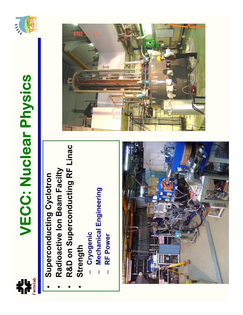
VECC: Nuclear Physics
VECC: Nuclear Physics
VECC: Nuclear Physics
VECC: Nuclear Physics
•Superconducting Cyclotron
•Radioactive Ion Beam Facilty
•R&D on Superconducting RF Linac
•Strength
–Cryogenic
–Mechanical Engineering
–RF Power
RRCAT: Indus
RRCAT: Indus
RRCAT: Indus
RRCAT: Indus- ---II IIIIII
RF Cavities installed in Indus-2 Ring
Indus-2 Ring in the Tunnel
RF Cavities installed in Indus-2 Ring
Long Straight Section LS-6 Assembly
Transport Line-3 Joining on to Indus-2
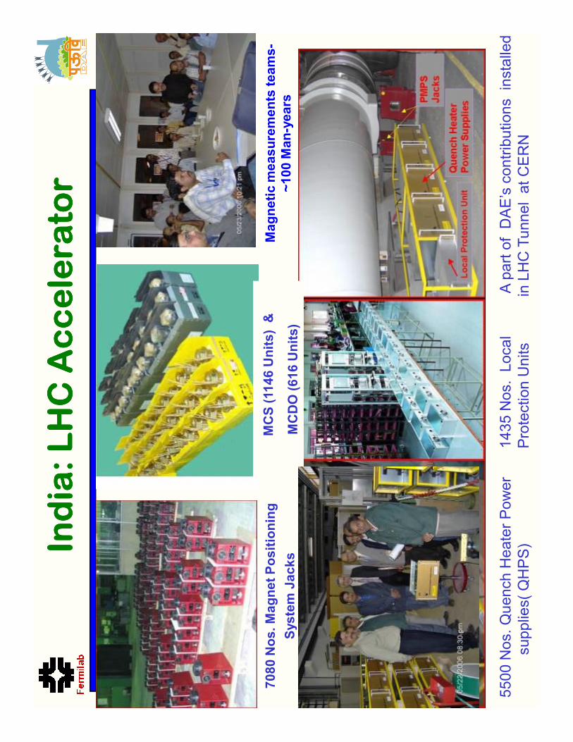
India: LHC Accelerator
India: LHC Accelerator
India: LHC Accelerator
India: LHC Accelerator
7080 Nos. Magnet Positioning
System Jacks
MCS (1146 Units) &
MCDO (616 Units)
Magnetic measurements teams-
~100 Man-years
System Jacks
MCDO (616 Units)
~100 Man-years
5500 Nos. Quench Heater Power
supplies( QHPS)
1435 Nos. Local
Protection Units
A part of DAE’s contributions installed
in LHC Tunnel at CERN
Nuclear Power Reactor
Nuclear Power Reactor
Nuclear Power Reactor
Nuclear Power Reactor
CD-3 to CD-4 in Five yrs.
Indo-US Nuclear Treaty
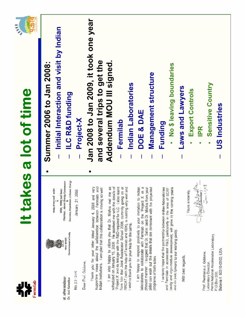
It takes a lot of time
It takes a lot of time
It takes a lot of time
It takes a lot of time
•Summer 2006 to Jan 2008:
–Initial Interaction and visit by Indian
–ILC R&D funding
–Project-X
•Jan 2008 to Jan 2009, it took one year
and several trips to get the
Addendum MOU III signed.
–Fermilab
–Fermilab
–Indian Laboratories
–DOE & DAE
–Management structure
–Funding
•No $ leaving boundaries
–Laws and Lawyers
•Export Controls
•IPR
•Sensitive Country
–US Industries
Developing US Collaboration W
ith India
Developing US Collaboration W
ith India
Developing US Collaboration W
ith India
Developing US Collaboration W
ith India
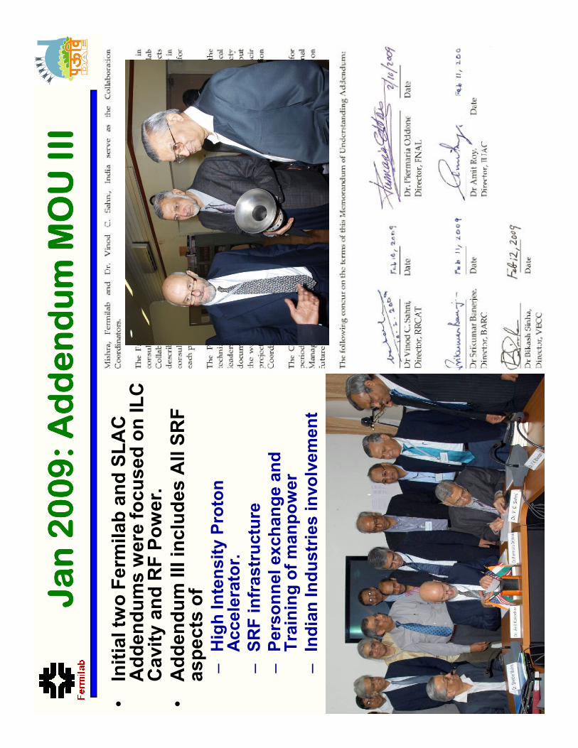
Jan 2009: Addendum MOU III
Jan 2009: Addendum MOU III
Jan 2009: Addendum MOU III
Jan 2009: Addendum MOU III
•Initial two Fermilab and SLAC
Addendums were focused on ILC
Cavity and RF Power.
•Addendum III includes All SRF
aspects of
–High Intensity Proton
Accelerator.
–SRF infrastructure
–Personnel exchange and
Training of manpower
Training of manpower
–Indian Industries involvement
•On Jan 9, 2006, US (Fermilab, SLAC, Jlab, Cornell) and
Indian Institutions (BARC, RRCAT, VECC, IUAC, DU)
signed an MOU to collaborate on Accelerator and High
Energy Physics
•We are collaborating under four addendums to the
MOU (http://iifc.fnal.gov)
MOU: US and Indian Laboratories
MOU: US and Indian Laboratories
MOU: US and Indian Laboratories
MOU: US and Indian Laboratories
MOU (http://iifc.fnal.gov)
1.Fermilab, RRCAT, BARC, IUAC and VECC Collaboration on
ILC Main LinacSRF Accelerator Technology R&D
2.SLAC, RRCAT, BARC, IUAC and VECC Collaboration on ILC
RF Power Sources and Beam Dump Design R&D
3.Fermilab and Indian Accelerator Laboratories Collaboration
on High Intensity Proton Accelerator and SRF Infrastructure
Development (Phase I)
4.US and Indian Institutions Collaboration on Neutrino Physics,
Related Experiments and Detector Development.
17
Ferm
ilab Next 10 yrs Strategy
Ferm
ilab Next 10 yrs Strategy
Ferm
ilab Next 10 yrs Strategy
Ferm
ilab Next 10 yrs Strategy
18
•A multi-MW Proton Source, Project-X, is the main part
of Fermilab’s strategy for future development of the
accelerator complex.
–Project-X is designed to provide flexibility in evolving Fermilab
program in response to research results from the LHC
Indian Next 10
Indian Next 10
Indian Next 10
Indian Next 10- ---15 yrs Strategy
15 yrs Strategy
15 yrs Strategy
15 yrs Strategy
19
•A multi-MW Proton Source is one of part of 3rd stage
–Multi MW CW beam at 1-2 GeV (similar to Fermilab Project-X)
could be the accelerator technology demonstration project
corresponding to 10s of MW electrical power if applied to a
suitable Accelerator Driven Subcritical Reactor.
Phase I: R&D Indian Institutions
Phase I: R&D Indian Institutions
Phase I: R&D Indian Institutions
Phase I: R&D Indian Institutions
•Fermilab is developing HIPA (Project-X) as a national
project with International participation.
–Indian DAE laboratories are 1st international partner.
•Indian Accelerator Program for Nuclear Energy and
Fermilab High Intensity Proton Accelerator program
are aligned in design.
Indian Institution
Phase 1: Deliverable
Phase 1: Deliverable
Phase 1: Deliverable
Phase 1: Deliverable
•SSR1 Cavity
•650 MHz,
β
β
β
β = 0.9 cavity design, prototype and
fabrication
•650 MHz Cryomodule design
–He Vessel
–Blade Tuner
–Blade Tuner
•SRF Infrastructure
–Vertical Test Stand design
–Horizontal Test Stand design and cryostat
–Cryomodule Test Stand design and cryostat
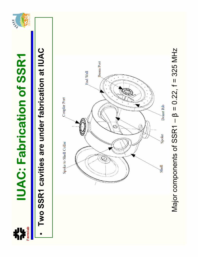
IUAC: Fabrication of SSR1
IUAC: Fabrication of SSR1
IUAC: Fabrication of SSR1
IUAC: Fabrication of SSR1
•Two SSR1 cavities are under fabrication at IUAC
Major components of SSR1 –
β βββ= 0.22, f = 325 MHz
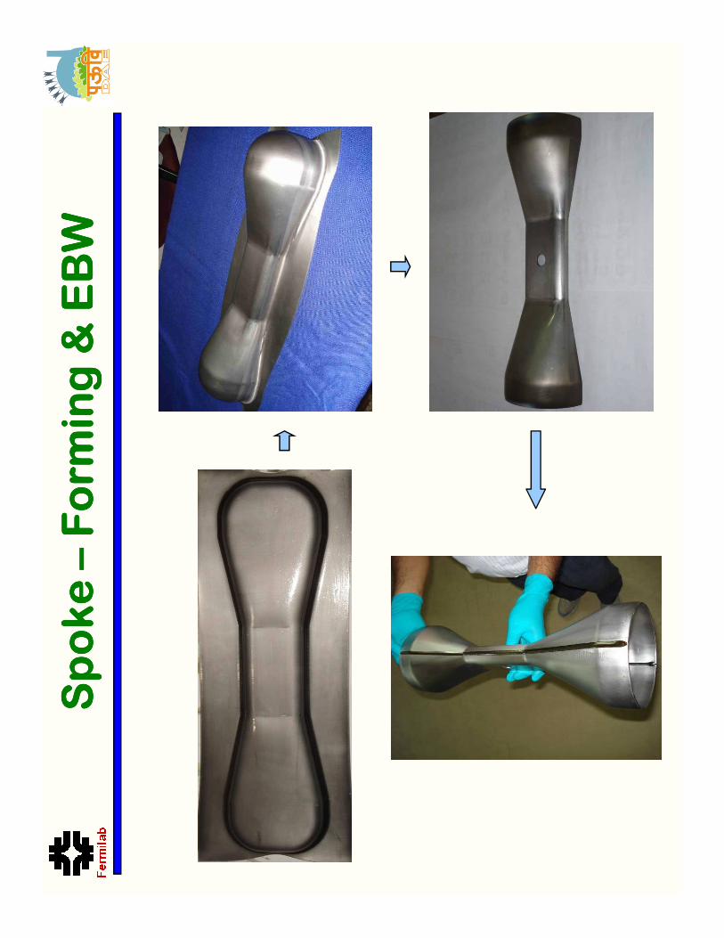
Spoke
Spoke
Spoke
Spoke – –––Form
ing & EBW
Form
ing & EBW
Form
ing & EBW
Form
ing & EBW
Shell
Shell
Shell
Shell – –––Rolling & EBW
Rolling & EBW
Rolling & EBW
Rolling & EBW
End W
all
End W
all
End W
all
End W
all - ---Form
ing
Form
ing
Form
ing
Form
ing
Niobium Coupler Port pullout
Power Coupler Port -Tubes
Developed forming tooling & process for 1.3 GHz SCRF cavity.
Elliptical Cavity:
Elliptical Cavity:
Elliptical Cavity:
Elliptical Cavity:
Form
ing and Machining
Form
ing and Machining
Form
ing and Machining
Form
ing and Machining
Form
ed Niobium Half cell
Inspection
Form
ing
Machining
This compact & dedicated machine it
Beam pipe welding
Manufacturing of Beam Pipe
Manufacturing of Beam Pipe
Manufacturing of Beam Pipe
Manufacturing of Beam Pipe
This compact & dedicated machine it
is suitable for clean room application
required for the rolling Niobium sheet.
Beam pipe welding
Beam pipe machining
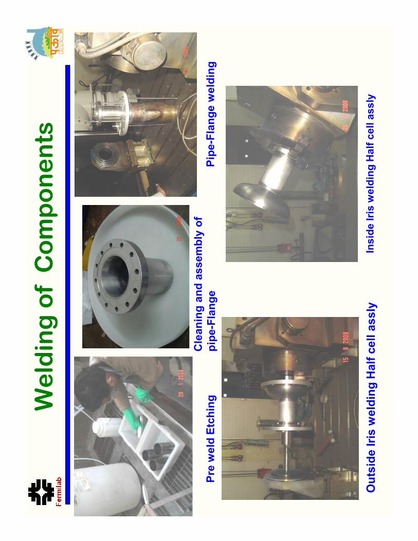
Cleaning and assembly of
pipe-Flange
Pipe-Flange welding
Pre weld EtchingWelding of Components
pipe-Flange
Pipe-Flange welding
Pre weld Etching
Outside Iris welding Half cell assly
Inside Iris welding Half cell assly
Half cell
assembly
Before
length (mm)
Before
Frequency
(MHz)
After length
(mm)
After frequency
(MHz)
Sensitivity
MHz/mm
AL -132
199.02
1286.5080
197.5
1289.7635
2.17
AL-133
198.82
1288.6623
197.92
1293.3215
5.17
Trimming , frequency and mechanical
measurements
Equator trimming
Frequency Measurement
Mechanical inspection
Equator Welding
Equator Welding
Equator Welding
Equator Welding
Setting inside IUAC EBW Chamber
Mechanical inspection
Frequency measurement
This work was carried out by
RRCAT in collaboration with
Ferm
ilab and IUAC.
Significant input was provided by
DESY and US Company AES
Leak testing (Stage wise + Final)
Leak testing (Stage wise + Final)
Leak testing (Stage wise + Final)
Leak testing (Stage wise + Final)
Leak testing (Stage wise + Final)
Leak testing (Stage wise + Final)
Leak testing (Stage wise + Final)
Leak testing (Stage wise + Final)
Leak testing of Niobium half cell
Leak testing of Single cell cavity
Leak testing at 300 K and 77 K,
Qualified for leak rate of 1 x 10 -10mbar.l/sec .
Leak testing of Niobium half cell
Leak testing of Single cell cavity
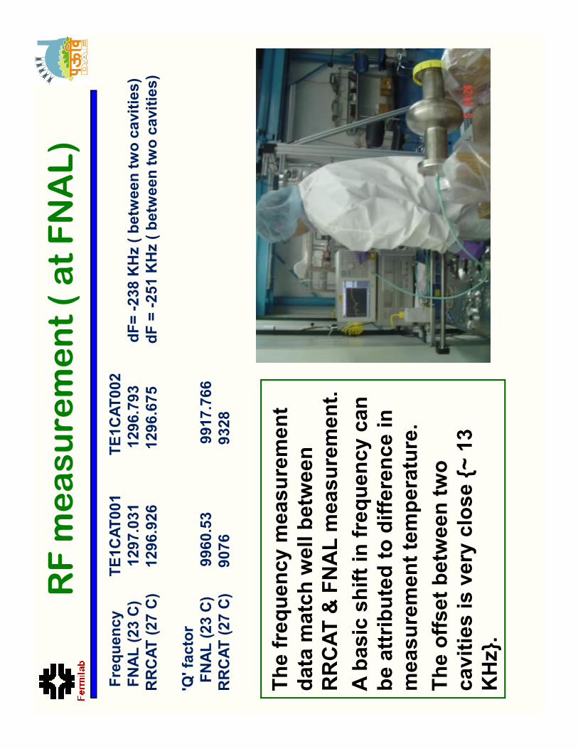
The frequency measurement
Frequency TE1CAT001
TE1CAT002
FNAL (23 C)
1297.031
1296.793
dF= -238 KHz ( between two cavities)
RRCAT (27 C) 1296.926
1296.675
dF = -251 KHz ( between two cavities)
'Q' factor
FNAL (23 C)
9960.53
9917.766
RRCAT (27 C)
9076
9328
RF measurement ( at FNAL)
The frequency measurement
data match well between
RRCAT & FNAL measurement.
A basic shift in frequency can
be attributed to difference in
measurement temperature.
The offset between two
cavities is very close {~ 13
KHz}.
Connecting to VTS inside clean room
Cavity assembly in to VTS (FNAL)
•The cavity was processed at
ANL using the standard
procedure and baked at Jlab.
Connecting to VTS inside clean room
Lowering in to Dewar
Mounted on the VTS
1.0E-01
1.0E+00
1.0E+01
1.0E+09
1.0E+10
1.0E+11
Radiation [mR/h]
Q0
TE1CAT002 -Q vs E
Test on 3/3/2010
No Field Emission
Quench at Equator
1 111- ---cell Cavity 2 K VTS test result
cell Cavity 2 K VTS test result
cell Cavity 2 K VTS test result
cell Cavity 2 K VTS test result
1.0E-02
1.0E+08
010203040
Radiation [mR/h]
Eacc [MV/m]
The equator weld is a suspect. W
elding procedure.
These cavities have been barrel polished at Ferm
ilab and awaits further
processing and testing.
RRCAT in collaboration with IUAC will fabricate 2, 7 cell, 1300 MHz
cavities to validate their procedure and infrastructure.
•High RRR End Group under
machining from a Single Billet .
•The Three M
ajor suggestions
that have been incorporated are
–All flanges will be NbTiand not
END Group R&D
–All flanges will be NbTiand not
NbTiring embedded in Nbflange .
–HOM port length kept same but
location of joint changed.
–Some minor modifications on
flange thickness
650 MHz Cavity Design
650 MHz Cavity Design
650 MHz Cavity Design
650 MHz Cavity Design
Left cell Regular cell Right cell
•Fermilab, DU, RRCAT and VECCare collaborating on 650 MHz
elliptical cavity design.
36
7.02
α ααα
39.5
b
20
a
84.5
B
82.5
A
106.974
L
200.277
R
50
r
5.2
° °°°α ααα
38
b
18
a
84
B
82.5
A
103.75
L
200.277
R
50
r
7.02
α ααα
39.5
b
20
a
84.5
B
82.5
A
106.974
L
200.277
R
50
r
All dimensions are in m
m.
650 MHz, 1
650 MHz, 1
650 MHz, 1
650 MHz, 1- ---cell development
cell development
cell development
cell development
•Calculation of Mechanical Deformation for beta 0.90
single cell cavity
Both ends fixed
One end open
Applied Pressure= 2 Bar
Max stress = 33.4 M
Pa
Max Displacement= 85.5 um
Applied Pressure =2 bar
Max stress = 75.4 M
Pa
Max Displacement= 0.942 um
650 MHz,
650 MHz,
650 MHz,
650 MHz,
β βββ= 0.6 cavity design
= 0.6 cavity design
= 0.6 cavity design
= 0.6 cavity design
•VECC has been working on 704 MHz, b = 0.6 cavity
design, prototype and testing.
•Recently under IIFC discussions VECC have decided to
switch their frequency to 650 MHz
–Despite having significant infrastructure for 704 MHz
Option A-Single Pipe
Op
tio
n B
-S
up
po
rt o
n t
wo
Possible Options & their evaluation
Goal :Use Popular T4CM Cryomodule
design for FermilabProject X
-(Although cavity size is up by a factor of 2)
Evaluation Based on:
Internal Configuration of Cryomodule
Internal Configuration of Cryomodule
Internal Configuration of Cryomodule
Internal Configuration of Cryomodule
for 650 MHz Cavity
for 650 MHz Cavity
for 650 MHz Cavity
for 650 MHz Cavity
Option A-Single Pipe
support
Option D-Rectangular Duct support
with interception flange
Op
tio
n B
-S
up
po
rt o
n t
wo
pip
es
Option C-Rectangular Duct support
Evaluation Based on:
�Static heat leaks (approx)
�Pressure drop in HGR pipe
�Stiffness of the system (approx)
�Availability of pipes
�General Mech. Engineering
issues
Option Chosen for Detailed Analysis
Option E-
Vacuum Vessel with Dia46inches.
�Retaining essential features of T4CM
design.
�But incorporating Value Engineering
Changes.
The Cross section
D Model
The 3-D Model
The 3-D Model (Under designing)
The Final Model –External View
The 80K Therm
al Shield
The 5K Therm
al Shield
(only Upper segment)
Cavity Support System
(With Cavity of 650MHz)
The 650MHz cavity with helium Vessel
The 650MHz cavity
RRCAT: SRF Infrastructure
RRCAT: SRF Infrastructure
RRCAT: SRF Infrastructure
RRCAT: SRF Infrastructure
–Similar to ANL design bench for
electro-polishing of SCRF cavity
has been developed, it can
process up to nine cell cavity. The
stand is capable of :
•Rotating the cavity at 2-10 rpm.
•Holding the cavity in horizontal
position during processing & in
vertical position during draining/
vertical position during draining/
rinsing and for loading the
cathode
•Slip ring with 4 carbon brushes to
connect power supply.
•The flow circuit has been tested
with water.
•Acid pumps, valves & plumbing
have been procured.
•25V –1000A DC Power supply
has been procured.
Ultra Pure W
ater Plant
RRCAT: SRF Infrastructure
RRCAT: SRF Infrastructure
RRCAT: SRF Infrastructure
RRCAT: SRF Infrastructure
High Pressure Rinsing Set up in
Clean enclosure (Class 100)
RRCAT: Cavity RF Measurement
RRCAT: Cavity RF Measurement
RRCAT: Cavity RF Measurement
RRCAT: Cavity RF Measurement
RF FREQUENCY PEAKS OF SINGLE
CELL CAVITY
RF FREQUENCY PEAKS OF DUMB-BELL
PNEUMATICALLY OPERATED RF
FREQUENCY MEASUREMENT SETUP
RF MEASUREMENT SET UP FOR
FREQUENCY AND FIELD DISTRIBUTION
Indigenous Development of Nb
Indigenous Development of Nb
Indigenous Development of Nb
Indigenous Development of Nb
NFC, Hyderabad (materials
development)
RRCAT, Indore ( electrical and
superconducting properties,
elemental analysis)
SU
MM
AR
Y &
CO
MPA
RIS
ION
OF T
ES
T R
ES
ULTS
S.No.
Source
Sample ID
RRCAT RRR
Results
Measurement results
1NFC
Nb/N
FC
/I80N
b III/U
/B
96
( 20.03.09)
2NFC
Nb/N
FC
/IU
1/T
i cla
d e
xpt
98
( 06.04.09)
Cavity Processing Building(Expected to
be ready by m
id of 2011)
•The building will house clean rooms,
Electron Beam welding m
achine. High
Vacuum Annealing Furnace, Electro-
polishing setup, Centrifugal barrel polishing
machine etc.
SCRF Lab Building (Expected to be ready
by m
id of 2011)
by m
id of 2011)
•The building will house Cavity form
ing
facility, machining facilities, CMM, SIM
S,
material testing facility etc
Ferm
ilab has shared infrastructure inform
ation with RRCAT.
Bid for Electron Beam W
elder with specifications similar to
AES is out.
AES has agreed to collaborate with RRCAT on some of these
development.
•Indian Institutions have provided engineering resources
to design an upgraded Vertical Test Stand for Fermilab.
–It is being fabricated by a US vendor
using ARRA funds
–RRCAT also purchased one
•RRCAT has carried out design of the following:
–Liquid Helium Vessel Shell
Vertical Test Stand Design
Vertical Test Stand Design
Vertical Test Stand Design
Vertical Test Stand Design
VA
CU
UM
VE
SS
EL
LIQ
UID
HE
LIU
M
VE
SS
EL
80
K
SH
IELD
2K
MA
GN
ET
IC
SH
IELD
3-D
MO
DE
LS
OF
VT
S-2
VE
SS
ELS
VT
S-2
TO
P P
LA
TE
–C
RY
OG
EN
IC &
VA
CU
UM
IN
SE
RT
S
–Liquid Helium Vessel Shell
–Liquid Helium Vessel Top Flange
–Vacuum Vessel Shell
–Vacuum Vessel Flange
–Top Insert Plate
•RRCAT has also verified the design of following
by Analysis
–Assembly of LHe Vessel Top Flange, Weld Rim
–Top Insert Plate
–Assembly of Vacuum Vessel Flange, LHe Vessel
Flange, Top Plate, Support Pads
–Magnetic Shield design –300K & 2K
Horizontal Test Stand (HTS-2)
•Fermilab has fabricated and is operating the first US
Horizontal Test Stand for 1.3 GHz elliptical cavities.
•Indian collaboration is designing an upgraded
Horizontal Test Stand for Fermilab and RRCAT.
–Test a combination of two cavities and/or magnet
–650 MHz and 1300 MHz cavities
–CW or pulse mode testing of cavities
A 3-D model of the
HTS-2 being designed
–CW or pulse mode testing of cavities
–Incorporating modifications based on operational experience
of HTS-1
Phase II: Discussions
Phase II: Discussions
Phase II: Discussions
Phase II: Discussions
•The Phase II of this collaboration is under discussion. It
is expected to expand the collaboration to all non SRF
areas of Project-X
–But it would be tied to the Phase III (construction of Project-X at
Fermilab)
•Elements of Phase II: (Very Preliminary)
–Front End: Source and RFQ
–325 MHz RF Power
–Instrumentations and Controls
–Superconducting Magnet
–Cryogenics
BARC: ECR Ion Source
BARC: ECR Ion Source
BARC: ECR Ion Source
BARC: ECR Ion Source
•Five electrodes
•2.45 GHz
•50 keV
•50 mA
•0.02 πcm-m
rad
Schematic of the ECR Ion Source
Ion source with 3 electrode extraction system
made &
Testing is in progress
Frequency
352.21 MHz
Energy
50 keV/ 3 MeV
Input current
30 mA
Vane voltage
80 kV
1. Bunching 2. Focusing 3. A
cceleration
RFQ Parameters
RFQ Parameters
RFQ Parameters
RFQ Parameters
Vane voltage
80 kV
Avg. Aperture R0
3.63-4.53 mm
Length
4 m
Total RF power
500 kW
Transmission
98%
•Design of a 325 MHz RFQ has started
�Total Power Gain : 20 dB
�3dB Band width : 10 MHz
�No. of modules : 4 plus 1 drive module
�Efficiency : 50%
�Devices LR301, DMD1029
�VSWR of each Module & Total amplifier : <1.2
�Wilkinson designed based power combiners /splitters
at 2KW (1:8) and 1KW (1:4) power levels
�At1KW,withtransm
issionloss
of<7%.
RF amplifier set up
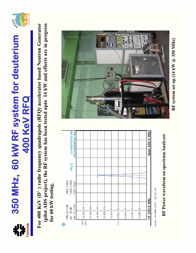
BARC: 350 MHz, 700 W
BARC: 350 MHz, 700 W
BARC: 350 MHz, 700 W
BARC: 350 MHz, 700 W
Solid
Solid
Solid
Solid- ---state Amplifier
state Amplifier
state Amplifier
state Amplifier
�At1KW,withtransm
issionloss
of<7%.
�Return
Loss
:>20dB
atcombiningportand
>13dB
atdividingports
�Isolation>28dB
�8modulestestset-upfor2.5
kW
isunderway
Single RF module
1:8, 2 kW power combiner
1:4, 1 kW power combiner
671.616 W
895.488 W
1.119 kW
1.343 kW
1.567 kW
1.791 kW
2.015 kW
M1[1]
2.010401123 kW
350.000000000 MHz
* *
RBW
VBW
SWT
1 MHz
100 kHz
5ms
Offs50.0 dB
Ref 2.2 kW
Att30 dB
1AP
Clrw
SGL
M1
CW m
ode results:
•Frequency: 350 M
Hz
•Power: 2000 +Watt (C
W)
•Gain: 15 dB
Tetrode and its
cavity
DC Bias
supplies
and input
RF driver
A new
RF driver for 60 kW RF system
has been developed based on
tetrode TH 393. Efforts are being made to test it at 3+ kW (CW) level.