The rod image: a new method for the calculation of pumpefficiency in reflecting close-coupled cavities
Franco Docchio
Reflecting close-coupled cavities for solid-state lasers often provide beams of better quality, although with aslightly lower efficiency compared with those of the usual elliptical cavities. A new method for thecalculation of efficiency in reflecting close-coupled cavities is proposed. Examples of efficiency calculationsare discussed.
1. Introduction
In recent years there has been a growing demand forcompact, efficient solid-state laser sources. The usesof these sources range from industrial applications,such as metalworking and resistor trimming, to bio-medical applications such as optical microsurgery, andto military applications, such as range-finding andtarget designation.
Apart from the widely used Nd:YAG laser, of partic-ular interest in recent times are eye-safe lasers, such asthe erbium:YAG, which have the advantage of emit-ting in a spectral region where the retinal damage isminimum.'
For all the aforementioned applications, compact-ness of the laser source is of paramount importance. Atypical example is portable range finders2 or opticalmicrosurgery, where the laser is connected to a slitlamp.3-5 High pumping efficiency is another stringentrequirement for laser sources, which can even be bat-tery operated. Finally, for a number of uses uniformlight distribution in the active material is also a re-quirement to obtain a good mode quality in the outputbeam even with unstable resonators.
All these requirements push toward the design ofnew kinds of pumping cavity to increase the pumpingefficiency, decrease the dimensions of the laser, andprovide a uniform light distribution in the active mate-rial. Elliptical or bielliptical, circular, close-coupled(reflective or diffusive), or even arbitrarily shaped cav-
The author is with Centro di Elettronica Quantistica e Strumenta-zione Elettronica del CNR, Istituto di Fisica del Politecnico, PiazzaLeonardo da Vinci 32, 20133 Milano, Italy.
ities are all possible candidates, depending on whichone, among efficiency, compactness, or beam quality isthe most important parameter.
As a guideline for the designer, methods for thecalculation a priori of the pumping efficiency of laserheads are very important. A number of methods forpumping efficiency and mode quality calculation havebeen developed.6 The most extensively studied areelliptical or multielliptical cavities; the peculiar geom-etry of these cavities permits simple geometrical con-siderations to find the ratio of the light entering theactive material to the light emitted by the pumpsource.7 -10 Other kinds of cavity are more difficult tocharacterize by these methods. Therefore, proce-dures based on the Monte Carlo (or ray tracing) meth-od have been developed for both reflecting and diffu-sive cavities"" 2; in addition, in the case of diffusivecavities the efficiency can also be calculated by a pure-ly thermodynamic approach.13 Apart from the MonteCarlo method which is time-consuming, a method forcalculating the pumping efficiency in reflecting cavi-ties of nonelliptical shape is still lacking. Further-more, unlike elliptical cavities, where most of the raysenter the rod after one reflection, in the case of nonel-liptical cavities multiple reflections from the cavitywalls can give a predominant contribution to the effi-ciency. Therefore restriction to the first reflection,usually adopted for elliptical cavities, is not valid.
In our laboratory we have developed a laser with anovel type of reflecting close-coupled (RCC) cavity forapplications to ophthalmic microsurgery. With theaim of comparing this pumping cavity with both ellip-tical and diffusive close-coupled cavities, we developeda method of calculating the pumping efficiency in areflecting close-coupled cavity. This method can becalled the rod image (RI) method; it has the advantageover the Monte Carlo method of a very short comput-ing time; furthermore, unlike geometrical approaches,it allows for multiple reflections.
We now describe the rod image (RI) method for RCCcavities of solid-state lasers. The typical shape ofRCC cavity is illustrated in Fig. 1(a). It generallyconsists of two flat surfaces, one on each side of therod-lamp assembly, and two other surfaces, of arbi-trary shape but often circular, at the rear side of the rodand of the lamp.
The efficiency of a laser pump cavity can be ex-pressed as the fraction of the energy emitted by thelamp which enters the rod. If the reflectivity a of thecavity surface is not unity, the power of each ray mustbe multiplied by a coefficient a , where M is the num-ber of reflections that the ray undergoes between thelamp and the rod.
Let us consider the lamp as a Lambertian source;then rays are emitted from every point on the surfaceof the lamp, whose power has an angular dependence ofthe form P(q) = P0 cost, where the angle X is calculatedwith respect to the normal to the lamp surface.
A light ray that leaves the lamp at an angle 0 withrespect to the interaxis direction, from a point Q of thelamp itself, reaches the rod after a number of reflec-tions N. This, from the standpoint of geometricaloptics, is equivalent to saying that the ray emittedfrom the lamp reaches an image of order M of the rod,obtained with respect to the various portions of thereflector. Figure 1(b) is an example of such a situa-tion, where the reflector is schematically composed oftwo flat surfaces: here a first ray, emitted at angle 01with respect to the interaxis direction, reaches the rod[R(O)] directly without any reflection (M = 0); twoother rays, emitted at angles 02 and 03, respectively,reach the rod after one reflection, or equivalently theyreach the first-order image of the rod called R(1) andR(-1).
Given reflector geometry, it is possible to constructwhat can be called an image set of the rod, consisting ofall the rod images as they are seen by an observerplaced at the lamp position. An order number M isattributed to each of the images, according to the num-ber of reflections that a ray leaving the lamp undergoesbefore reaching the lamp. The construction of theimages is particularly simple in the case of cavitiesmainly consisting of flat surfaces: this is our close-coupled cavity. For cylindrical, elliptical, or differ-ently shaped surfaces, the image set can be constructedeither geometrically or analytically.
Figure 2 shows a pattern of images that can be gener-ated by a cavity like that of Fig. 1(a). In this figure,R(0) is the rod (M = 0); R(+1) and R(-1) are the twofirst-order images of the rod, as seen by the observerplaced at 0, with respect to the lateral flat surfaces;R(2) and R(4) are the first-order images with respect tothe front and back cylindrical surfaces; and R(3) andR(5) are two second-order images [the reflection of,respectively, R(+1) and R(-1)]. The figure alsoshows, qualitatively, a first-order image of the lamp,with respect to that portion of the reflector placedbehind the lamp.
The basic concept of the RI method is therefore asfollows: once the geometrical space around the lampis filled with a number of images of the rod, each oforder number M, the reflector is ideally removed. Anyray that leaves the lamp can reach, depending on thedirection, one or more images of the rod and be ab-sorbed; alternatively, it can travel without reachingany of the images of the pattern. Therefore, the effi-ciency of the cavity can be calculated by, first, sum-ming all the radiant power associated with the raysthat leave the lamp and reach the images of the rod,each weighed by a factor that takes into account thereflection number M; then the sum is divided by theoverall radiant power of the rays that leave the lamp inany direction.
The RI method, as illustrated so far, is no differentfrom a conventional ray tracing method, if we considereach ray emitted by the lamp individually. The real
0a) b)
Fig. 1. Close-coupled reflecting cavity. (a) Cross sectional of thecavity: F.L. = flashlamp; L.R. = laser rod. (b) Illustration of the RImethod: the close-coupled cavity with the lateral walls removed
and replaced with the first-order images of the rod.
Fig. 2. Cross section of the rod-images ensemble including the
images obtained by reflection through the cylindrical walls.
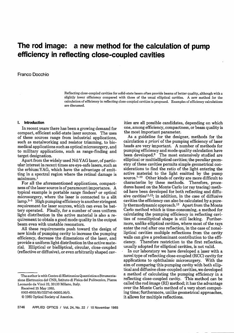
intersected image, each weighed by its reflection coef-ficient an. Using Eq. (1), we obtain
PP 1 +P2 =an P(S)dS + a' P(S)dS. (2)SI fS3
By generalizing to the ith bundle P(0i) in direction Oi, (i= 1 .. .N), we have
S d
Ni-1)
Fig. 3. (a) Energy distribution inside a bundle of parallel rays.Intersection of a bundle of rays with two images of the rod.
(b)
advantage of the method comes from the fact that nowall the rays travel in a straight line; therefore they canbe treated collectively. In fact, all the rays that leavethe surface of the lamp in the same direction can begrouped together to form a bundle of parallel rays, asshown in Fig. 3(a).
The radiant power distribution within each of thesebundles can be easily calculated. With reference tothe figure, we call Po the radiant power emitted by thelamp at every point of the surface perpendicular to thetangent to the surface. Let us consider the bundle ofrays that emerge from the lamp surface in a givendirection, say, the vertical one. Let 0 be the angleformed by the perpendicular to the surface at everypoint with the vertical direction, and S = OH be theabscissa of the generic point Q. Since from every pointof the lamp rays are emitted with a Lambertian distri-bution, we have, from Fig. 3(a), S = R sin(0), and P(S)= Po cos(0). Therefore,
P(S) = R-Po(R 2 S2)112 . (1)
Thus, at any given direction, a bundle of rays emit-ted in that direction has a power distribution given byEq. (1) when the abscissa S is taken along a diameterperpendicular to the considered direction.
Each bundle of rays reaches either totally, partially,or not at all any of the images of the rod in a pattern likethat of Fig. 2. It can also happen that, depending onthe relative dimensions of the cavity, of the lamp, andof the rod, a part of the bundle intersects one image,another part intersects another image, and the remain-ing part does not have intersecting points with anyimage in the cavity. The situation is illustrated in Fig.3(b), where a bundle partially intersects an nth-orderreflection and partly an (n + 1)th-order reflection. Ifwe project the intersection points on the lamp diame-ter perpendicular to the bundle direction, we obtain,for the nth image, points S and S2 and, for the (n +1)th image, points S3 and S4. Then, the power deliv-ered to the rod is the sum of the power delivered to each
(3)
Assuming that N bundles will cover the full 2ir angle,we obtain Nvalues of P(Oi). Then the efficiency can becalculated as
NP(o0)
N P(S)dSJRI,where
JRL
RL
(4)
P(S)dS
is the total power emitted by the lamp in the directionAs. The above procedure can be easily transposed to acomputer program. The input parameters of the pro-cedure are the cavity parameters, i.e., the location,shape, and reflection order of the various images of therod, and the dimensions of the lamp.
The lamp is normally assumed to be partiallyopaque to its own radiation.' 4
The fraction of power reabsorbed by the lamp de-pends on the plasma conditions inside the lamp, andhence on the current flowing into it, as well as on thelight wavelength. Reabsorption of the light by thesource has been considered by tracing the images of thelamp with respect to the reflector (Fig. 2 shows only thefirst-order image of the lamp). Whenever a bundle, orpart of it, crosses one such image, the energy associatedwith it must be weighed by a factor that takes intoaccount the absorption of the radiation by the lamp.
In the same way the rod absorbs the lamp radiationaccording to the absorption spectrum of the Nd3+ ions;thus the contribution to the efficiency given by theimage of RR with respect to the cylindrical back reflec-tor is weighed by a suitable factor.
To assess the procedure, two major assumptions aremade: first, the reflectance factor a has been assumedto be independent of the angle of incidence on thereflector surface. This is, strictly speaking, not true'5;however, in a geometry like that of a RCC cavity mostof the angles of incidence fall within a region where thereflectance factor is almost angle-independent.
The other assumption made so far is that no refrac-tion takes place when a bundle crosses the rod or thelamp. We believe that, to a first approximation, thiseffect could be reasonably neglected. However, thiscould indeed be taken into account by a procedure ofpower transfer from one bundle to another after cross-ing the rod, which would simulate the effect of refrac-tion quite well.
Fig. 4. Plot of the lamp energy transfer efficiency vs the angle 0with respect to the horizontal plane: upper lines, images by lateralwalls; lower lines, images by cylindrical walls; (a) one reflection; (b)
twelve reflections.
Ill. Efficiency Calculations for RCC Cavities andDiscussion
With the aid of the RI procedure we have calculatedthe efficiency of the RCC cavity developed in our lab-oratory and studied its dependence on the design pa-rameters. First, we verified the importance of multi-ple reflections of the cavity walls on the efficiency ofthe cavity. Figure 4 shows a plot of the power thatreaches the rod for ray bundles emitted by the lamp atdifferent angles. Figure 4(a) refers to the case of onlyone reflection from the cavity walls, while Fig. 4(b)refers to twelve reflections. In each figure, the uppercurve is related to the reflections by the lateral surfacesof the cavities (0 < 0 •< r), while the lower curve refersto the contribution of the two cylindrical surfaces.The parameters of the cavity are RL = 2 mm, RR = 3mm, Rext = 4.5mm, and L = 11 mm. A value of 0.9 waschosen for the wall reflectivity a. According to Ref.14, the transmission coefficient of the lamp was 0.5,and the transmission coefficient of the rod (integratedover the absorption bands of Nd:YAG) was -0.4. Anoticeable difference is seen between the two sets ofcurves due to the presence of the higher-order images.
UJ0LUa.
0zLU
0U-LI.LU
0 2 4 6 8 10 12
NUMBER OF REFLECTIONS
Fig. 5. Graph of the cavity efficiency vs the number of reflectionsfor a = 0.9 and a = 1: full lines, only lateral surfaces; dotted lines,
including cylindrical surfaces.
Figure 5 shows a plot of the efficiency, as a functionof the number of reflections, for two values of the wallreflectivity a = 0.9 and a = 1. This last value wasconsidered with the aim of better comparing the effi-ciency of a RCC cavity with that of an elliptical cavitywith the method of Bowness.9 Solid curves refer to thecontribution of the flat surfaces alone, while dashedcurves include the contribution of the cylindrical walls.It can be clearly seen that, unlike the case of ellipticalcavities, the effect of multiple reflection from the cavi-ty walls is of great importance in the efficiency calcula-tion. In fact, from Fig. 5 we note that a plateau isreached only for a number of reflections >10 and thatthe efficiency obtained for one reflection is only 50% ofthe overall contribution for a high number of reflec-tions.
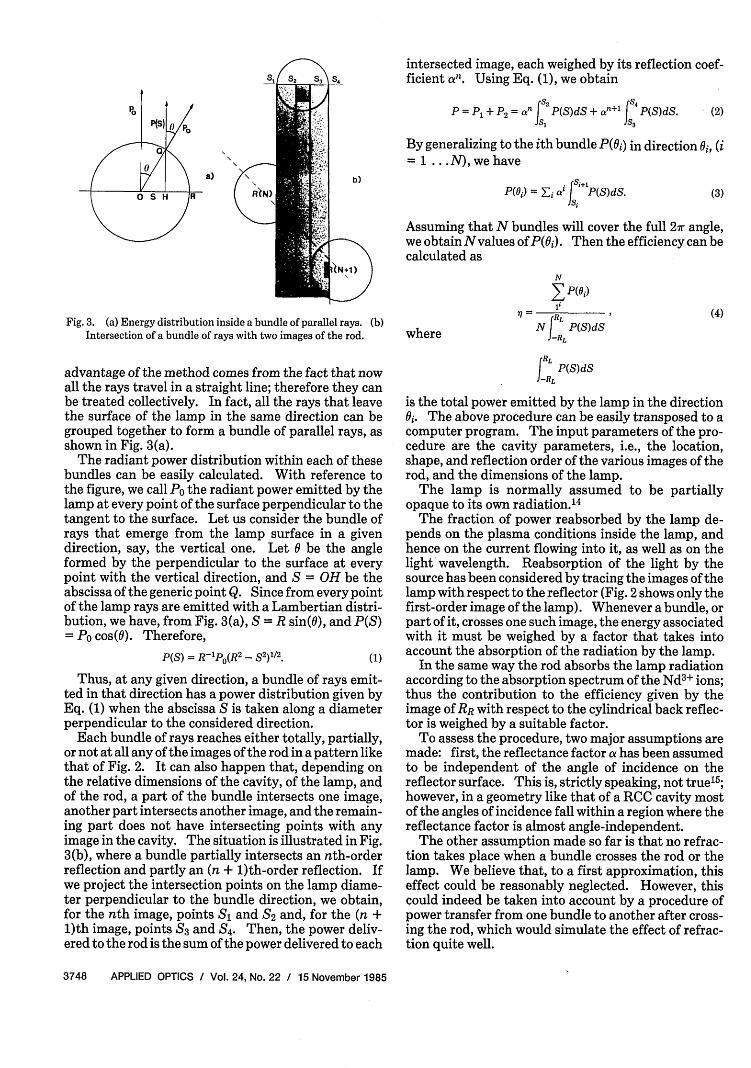
Figures 6(a), (b), (c), and (d) show the dependence ofthe efficiency on the various cavity parameters, name-ly, cavity length, cavity width, lamp diameter, and roddiameter, respectively, for three different values of thewall reflectivity.
From Fig. S and from the set of Fig. 6 we can draw thefollowing conclusions:
(a) The contribution of the cylindrical surfaces ofthe efficiency is only a small fraction of the overallefficiency [Fig. 5(a)]; presumably a redesign of thesesurfaces by using other than cylindrical surfaces couldincrease the efficiency.
(b) The cavity should be as short [Fig. 6(a)] and asnarrow [Fig. 6(b)] as possible, the other parametersbeing equal.
(c) Due to the cavity geometry, transfer efficiency ismore sensitive to the lamp diameter [Fig. 6(c)] than tothe rod diameter [Fig. 6(d)].
The RI method can be easily adapted to types ofcavity other than the RCC cavity. For example, it canbe demonstrated that the image of the rod, as seen bythe lamp location with respect to an elliptical pumpcavity, has the shape of a circumference with its centerat the lamp and radius 4c, where c is the distance of the
Fig. 6. Dependence of the efficiency of the close-coupled reflecting cavity on the cavity parameters for three values of the wall reflectivity(0.9, 0.95, 1): (a) dependence on the interaxis length; (b) dependence on the cavity width; (c) dependence on the lamp diameter; (d)
dependence on the rod diameter.
rod from the center of the ellipse. The relatively lowimportance of multiple reflections in the elliptical cav-ity can be verified, since most of the rays reach eitherthe rod or its first image, except for those masked bythe lamp. In this case one finds that the transferefficiency is mainly affected by
(a) the fraction of energy absorbed by the lampwhich depends on the lamp diameter and on the cavitydimensions (in particular the eccentricity of the el-lipse);
(b) the relative amount of direct and reflected lightreaching the rod.
IV. Conclusions
The RI method has proved to be effective for calcu-lation of the efficiency of close-coupled reflecting cavi-ties. The method requires that the designer deter-mine the rod image pattern for a given shape of cavity,but it requires a much reduced computation time com-pared with ray tracing methods. It has been demon-strated that, in a RCC cavity, efforts to increase theefficiency by properly shaping the rear reflectors areneeded to increase the cavity efficiency. Work is inprogress to design new types of rear surface for a RCC
cavity, and to characterize them, with the purpose offurther increasing the efficiency of the cavity. Work isalso in progress to adapt the procedure to the determi-nation of the power distribution in the rod, with theaim of evaluating, for different cavity shapes, the beamquality of the laser beam.
The author wishes to thank C. A. Sacchi and 0.Svelto for their suggestions and for the careful readingof the manuscript.
References
1. K. S. Bagdasarov, V. I. Zhekov, L. A. Kulevskii, v. A. Lobachev,T. M. Murina, and A. M. Prokhorov, "Giant Laser RadiationPulses from Erbium Doped YAG Crystals," Sov. J. QuantumElectron. 10, 1127 (1980).
2. M. L. Stitch, "Laser Range Finding," in LaserHandbook, Vol. 2,F. T. Arecchi and E. 0. Schulz-Dubois, Eds. (North-Holland,Amsterdam, 1972), pp. 1745-1784.
3. F. Fankhauser, "Q-Switch Laser: Principles and Clinical Re-sults," in YAG Laser Ophthalmic Microsurgery, S. Trokel, Ed.(Appleton-Century-Crofts, New York, 1983), pp. 101-146.
4. M. A. Mainster, D. Sliney, D. Belcher III, and S. M. Buzney,"Laser Photodisruptors: Damage Mechanisms, InstrumentDesign, and Safety, " Ophthalmol. 90, 973 (1973).
5. F. Docchio, A. Fumagalli, 0. Svelto, and M. Guerini, "HighEfficiency Compact Nd:YAG Laser for Eye Microsurgery," La-sers in Med. Sci. 1, (1986), to be published.
6. For an extensive review see W. Koechner, Solid-State LaserEngineering (Springer-Verlag, New York, 1976), Chap. 6, pp.300-342, and references therein.
7. S. B. Schuldt and R. L. Aagard, "An Analysis of RadiationTransfer by Means of Elliptical Cylinder Reflectors," Appl. Opt.2, 509 (1963).
8. K. Kamiryo. T. Lano, and K. Matsutawa, "Optimum Design ofElliptical Pumping Chambers for Solid State Lasers," Jpn. J.Appl. Phys. 5, 1217 (1966).
9. C. Bowness, "On the Efficiency of Single and Multiple EllipticalLaser Cavities," Appl. Opt. 4, 103 (1965).
10. D. Fekete, "Effect of Multiple Reflections on the Design of anElliptic Cavity for Solid State Lasers," Appl. Opt. 5, 643 (1966).
11. D. R. Skinner and J. Tragellas-Williams, "Total Energy and
Energy Distribution in a Laser Crystal due to Optical Pumpingas Calculated by a Monte Carlo Method," Aust. J. Phys. 19, 1(1966).
12. E. J. Seppi, "New Monte Carlo Method and Review of PresentMethods for Calculating the Characteristics of Excitation Ge-ometries for Solid State Lasers," Institute for Defence Analysis,Science & Technology Division Contract DAGC 15-67-CO01(1970), p. 655.
13. J. Whittle and D. R. Skinner, "Transfer Efficiency Formula forDiffusely Reflecting Laser Pumping Cavities," Appl. Opt. 5,1179 (1966).
14. J. L. Emmett, A. L. Schawlow, and E. H. Weinberg, "DirectMeasurement of Xenon Flashtube Opacity" J. Appl. Phys. 35,2601 (1964).
15. R. Kingslake, Applied Optics and Optical Engineering (Aca-demic, New York, 1965), Vol. 3, pp. 318-320.
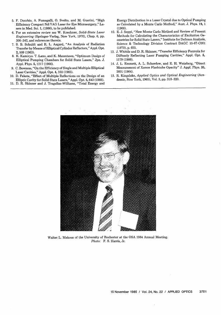
Walter. L. Makous of the University of Rochester at the OSA 1984 Annual Meeting.Photo: F. S. Harris, Jr.