ABSTRACT Composite materials have been used to repair high pressure
pipelines and piping for the better part of 20 years. The initial aim of composite repair technology was focused on reinforcing corrosion. However, composite materials are now used to reinforce a wide array of anomalies and features including dents, mechanical damage, vintage girth and seam welds, wrinkle bends, elbows, tees, branch connections, and even cracks.
In this paper the author provides an industry overview including
results and insights from multiple research programs sponsored by composite repair manufacturers, pipeline operators, and the Pipeline Research Council International, Inc. Discussions will also be included regarding the important role that the ASME PCC-2 and ISO 24817 composite repair standards have in ensuring that quality control measures are in place. The ongoing focus of these efforts has been to demonstrate to industry the capabilities that composite repair systems have to provide long-term solutions for reinforcing damaged equipment.
INTRODUCTION
The design of composite repair systems for reinforcing high pressure steel pipelines the design engineer must consider the behavior of both the composite and steel. In this regards the designer must not only understand how pipelines are designed and how composite materials respond to loading, he must see the design as a hybrid and understand the inter-dependent behavior of both the steel and the composite.
Over the past 20 years the author has evaluated more than 25 different composite repair systems. During this time period, a significant body of research has been accumulated, much of it favorable in terms of developing technically-sound composite designs; however, on occasion the author has observed poor test results. The central aim of this paper is to provide the reader with a resource for evaluating whether or not a composite repair system meets the design requirements for reinforcing high pressure pipeline systems. This foundation for this paper is built on observations of what has worked and what has not worked.
An important observation made in reviewing the body of research data is that not all composite repair systems perform equally. This will be demonstrated by some of the results provided in this paper. Some of the items highlighted in this paper include the need for composite repair systems to address the following subjects related
to validating the long-term performance capabilities of a given repair system. Meeting the minimum industry standards including a design
basis Performance-based testing Verification of design stresses Long-term performance (longevity and cyclic loading) Operating environments (water and temperature) Third party review Quality control
Any manufacturer of composite repair systems making installations on high pressure pipelines must demonstrate a working knowledge of the above areas. This includes a recognizing system limitations and an unwillingness to extrapolate performance capabilities. An excellent example concerns material performance at elevated temperatures. It is not enough to know the glass transition temperature or heat distortion temperature for the resin used in a composite repair; physical destructive testing must be performed at temperature to demonstrate capabilities.
The sections that follow integrate the above list as part of the overall discussion on achieving long-term performance capabilities. The top performing composite repair systems in the world have demonstrated the ability to perform at a level to ensure that a long-term repair solution is provided. The Background on Design of Repairs provides information on the design basis per ASME PCC-2 and the importance of material qualification. The Research Programs section provides the reader with an overview of the extensive body of research that has been conducted, with a specific discussion on a long-term burial study and a program that evaluated the performance of composite repair systems used to reinforce dents. BACKGROUND ON DESIGN OF REPAIRS
This section of the paper provides background concepts associated with designing a composite system for reinforcing damaged pipelines. Included are discussions on safety factors and material performance, as well as a review of stress/strain data to validate acceptable conditions in a composite system. Also included are results from previous testing programs that validated the designs of composite repair systems relative to the requirements of the composite repair standard, ASME PCC-2, Repair of Pressure Equipment and Piping, Part 4.
From a design standpoint, the operating pressures of gas and liquid transmission pipelines are based on the geometry of the selected pipe (diameter and wall thickness) and material properties (yield strength). Gas transmission pipelines, in particular, are assigned safety margins (design pressures) based on their proximity to buildings and people. Inherent in any discussion of the design of gas and liquid transmission pipelines is the concept of safety factors. When composite materials are used to repair high-pressure pipeline, their design must consider both the strain reduction in the reinforced steel, as well as considering stresses (or strains) in the composite material. Ideally, the composite must provide enough strain reduction in the steel to ensure that integrity is restored to the damaged sections of the pipeline; while at the same time possess sufficient stiffness to ensure that design stresses are not exceeded in the composite material that could potentially reduce its long-term performance.
The most fundamental technical issue associated with the design of a composite repair system centers on long-term performance. Because composite materials typically involve a polymer-based matrix (e.g., most often epoxy or urethane), the potential exists for time-dependent loss of strength. The key for the long-term performance of any composite repair system is based on the relationship between stresses in the composite at design conditions relative to failure strength of the composite material itself. While steel pipelines are typically designed with safety factors on ultimate tensile strength between 2 and 3, well-designed composite repair systems have safety factors relative to short-term failure strengths ranging from 7 to 10. These larger safety factors are to accommodate material degradation as a function of time and uncertainties associates with long-term performance.
The sections that follow provide information related to the design of composite repair systems based on performance-based testing to establish design strength for the composite materials. Testing to Validate Material Performance
A study completed by SES in 2010 on a composite repair system provides useful information related to establishing long-term design strength for a given composite system. As part of material-qualification testing required by ASME PCC-2, composite materials were applied on the outside surface of undamaged pipe samples that were held at a constant pressure level for 1,000 hours. Strain gages were used to measure strains in both the composite material and reinforced steel pipe. The stress levels to which the composite materials were subjected were used to establish the long-term design strength of the respective composite materials.
In addition to the 1,000-hour pressure hold, burst tests were conducted on three test samples reinforced with the composite repair system after the hold period was completed. Figure 1 plots data that were collected during this study. Several important observations are made in reviewing these data: At the design pressure of 1,778 psi (72% SMYS) for this
particular pipe material, the hoop strain was 900 microstrain (0.09%) in the unreinforced pipe sample.
With the addition of 0.188 inch of Armor Plate® Pipe Wrap, the pressure in the reinforced sample at the equivalent strain level of 0.09% increased to 2,420 psi (this is actually equal to 100% SMYS for the base pipe – extremely significant observation). A comparison of the data intersections along the dashed blue line implies that, when a composite thickness of 0.188 inch is added to the 12-inch nominal diameter pipe, the design pressure
increases from 1,778 psi to 2,420 psi (an increase of approximately 30%).
Similarly, if the pressure level is held constant at 1,778 psi, strains in the reinforced test samples decrease from 0.09% to 0.067% (strain reduction of approximately 26%). This is noted from the data intersections along the horizontal dashed green line (cf. Figure 1).
It is possible to use composite materials to reduce strain in a reinforced pipe for a particular design pressure. A critical variable in this approach is the design stress of the composite material. As long as the stress in the composite material is kept below a designated level, the long-term performance1 of the reinforcement is ensured. Validation of Design Stress
Another series of tests performed by SES for two composite manufacturers in 2011 involved installation and monitoring of strain gages on the composite material. Strain gages were installed within the composite repair system (i.e., on layers as they were installed around the pipe, identified as inter-layer strains) to measure strains within the repair during pressurization. This engineering technique reduces the guesswork associated with attempting to quantify actual stresses in the composite material during pressurization of the pipe. For composite materials (and for purposes of this discussion), stress is the product of strain and elastic modulus of the composite material. It is necessary to measure the elastic modulus via mechanical testing on composite coupons. Measuring inter-layer strain is essential to ensure that composite materials are not overstressed. Without these types of measurements, there is no assurance that repair materials are not overstressed (even at design conditions), which could lead to failure of the material.
Equally important, when composite reinforcement materials are overstressed their ability to provide the required reinforcement to damaged sections of pipe is reduced. When designing a composite repair system for long-term service, it is essential that the magnitude of stresses in the composite material not exceed a designated design level (i.e., long-term design stress). ASME PCC-2 provides a means for determining the long-term design stress based on using results from either 1,000 hour or 10,000 hour pressurized pipe samples (refer to the 1,000-hour test discussed in the preceding section). Until relatively recently, there has been no attempt to actually quantify hoop stresses in the composite material of a repair used to reinforce a corroded section of pipe at a designated pressure level.
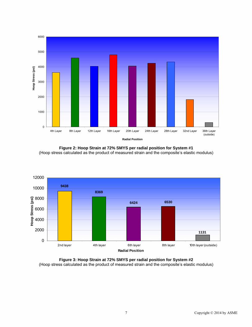
SES conducted tests on two different composite repair systems, both of which used E-glass fibers. The objectives in testing were two-fold. The first was to determine the actual distribution of strain in the layers of the composite reinforcement, specifically, determining which layers carried the greatest percentage of the load. The second objective was to measure the maximum stress (strain) in the composite material for comparison to the ASME PCC-2 long-term design stress (determined by the 1,000-hour test for each of the tested systems).
Figure 2 and Figure 3 plot hoop stress in the composite materials at 72% SMYS for Systems #1 and #2, respectively, as a function of
1 There is some debate as to what constitutes long-term. A 50-year design life is not uncommon when discussing composite repair design; however, careful consideration must also be made regarding the type of anomaly being repaired and the service conditions to which it is subjected (e.g. cyclic pressure).
radial position. Table 1 presents a summary of data for both systems measured at 72% SMYS, along with a comparison of the measured stresses to the respective long-term design stresses.
As a point of reference, when these two systems were used to repair a 12.75-inch x 0.375-inch, Grade X42 pipe having 75% corrosion, the cycles to failure when pressure-cycled at a stress range of 36% SMYS (ΔP = 36% to 72% SMYS) were 140,164 and 259,537 cycles for System #1 and System #2, respectively. Also, both of these systems ensured that strains in the corroded region of the pipe were limited to approximately 0.3% when the test sample was pressurized to 72% SMYS.
One of the most important observations in reviewing the data presented in Table 1 is the relatively large material strength design margins that exist for both systems, especially in relation to the short-term tensile strength. When comparing the measured stresses in System #1 and System #2, the ratios of mean tensile strength to maximum stress for the composite materials are 10.8 and 7.6, respectively. If the average stresses in the composite are considered based on the strain gage results, as opposed to the maximum stress reported in Table 1, the design margins are even larger. The significance of these design margins cannot be overstated. In order for a composite material to provide long-term reinforcement, it is essential that stresses in the composite material and reinforced steel be kept to a minimum. RESEARCH PROGRAMS
A significant body of research and testing work has been conducted to evaluate the reinforcement of high-pressure gas and liquid transmission pipelines using composite materials. The sources of this work have been independent investigations funded by individual composite repair manufacturers and pipeline operators, as well as the Pipeline Research Council Institute, Inc. (PRCI).
The sections that follow provide details on both the independent investigations funded by pipeline operators and composite repair manufacturers, as well as five programs sponsored (or co-sponsored) by PRCI. Independent Investigations Pipeline operators and composite repair companies have determined that an effective approach to quantifying the benefits of using composite materials to reinforce pipeline components and anomalies includes full-scale destructive testing. These tests have demonstrated that the level of reinforcement provided by the composite material can be quantified by considering both the strain reduction in the reinforced steel and the increase in stiffness associated with the combined properties of the steel and composite.
Although specific results are not included in this section of the paper, listed below are some of the independent investigations that have been conducted. Study to evaluate reinforcement of branch connections Reinforcement of wrinkle bends subjected to bending and
tension loads Study to address the effects of elevated temperatures Reinforcement of pipe fittings including elbows and tees Study to address the effects of internal pressure during
installation
PRCI Composite Studies As mentioned previously, PRCI has been instrumental in funding numerous studies focused on evaluating the use of composite repair systems. These studies have helped the pipeline industry improve their understanding regarding the capabilities of composite repair technologies in reinforcing a variety of anomalies. The brief write-up on PRCI programs presented here is not exhaustive and includes limited technical data; however, the intent is to communicate the range of studies that have been conducted focused on evaluating composite repair technology. Listed below are all of the PRCI studies that have been conducted to evaluate the performance of composite repair systems. Details associated with the MATR-3-4 long-term and MATR-3-5 dent studies are included in this paper. MATR-3-3 State-of-the-art assessment MATR-3-4 Long-term buried pipe MATR-3-5 Dent repair MATR-3-6 Subsea repair MATR-3-7 Vintage girth weld MATR-3-9 Establishing MAOP using composites MATR-3-10 Composite repair guidelines NDE-2-3 NDE of composite repair MATR-3-4: Long-term Repair of Corrosion. The program involved the burial of 12-inch nominal diameter pipe samples having machined corrosion and subjecting them to periodic cyclic pressures. After designated periods of time, pre-assigned groups of pipe samples were removed from burial and burst-tested. All of the manufacturers participated for at least three years, while five companies elected to participate for a 10-year period (the longer study is currently ongoing, while all samples have completed the 3-year testing program).
Prior to burial of the pipe samples, a series of baseline burst tests was conducted, designated as the “Year 0” burst tests. The results of these particular tests were important in establishing the optimum level of performance that could be expected from a given composite repair system. What was clear in studying the results from these tests is that not all composite repair systems perform equally. Subsequent to the first round of burst tests in 2008, it has become even clearer that some composite repair systems perform better than others. Of particular interest with the Year 0 burst tests was the level of strain reduction in the machined corrosion regions provided by the different composite repair systems.
The results for all tested systems are provided in Table 2. Listed below are average measurements at pressure levels equal to 72% SMYS. Product L performed poorly and the results provided below include the removal of this statistical outlier. All composite systems: 3,734 με (without Product L: 3,269 με) E-glass systems: 4,497 με (without Product L: 3,771 με) Carbon composite systems: 2,524 με
There are several important observations derived from the results of the MATR-3-4 study completed up to this point. The first is that at the present time there are commercially-available composite repair technologies that can provide long-term reinforcement to damaged pipelines. The second observation is that several of the systems had significant problems in reinforcing more severe corrosion damage, i.e., enough to warrant concern regarding their use
on high-pressure gas and liquid transmission pipelines. The final observation—and probably most important for operators in the context of actually using composite repair systems—is that the ASME PCC-2 and ISO 24817 standards are an excellent means for qualifying composite repair systems. Operators are cautioned in using composite repair systems that do not meet at least the minimum requirements of these particular standards, especially with regards to establishing a long-term design stress used to calculate the required thickness for a composite repair. MATR-3-5: Repair of Dents. With the execution of the MATR-3-4 project, PRCI members were interested in evaluating the use of composite materials for reinforcing dents, including dents interacting with ERW seam and girth welds. The PRCI MATR-3-5 study, Composite Repair of Mechanically-Damaged Pipes, was co-funded by PRCI and eight composite repair companies that included the following: Two rigid coil systems (one E-glass and one steel) Four carbon systems Four E-glass systems One steel sleeve system
The purpose of this program was to determine whether composite materials can effectively repair dents in high-pressure pipelines subjected to cyclic pressure service. Much like its predecessor MATR-3-4 program, which evaluated the long-term performance of composite repair systems in repairing corrosion, this program included the participation of several composite repair manufacturers and one steel sleeve manufacturer, whose contributions included funding, materials, and personnel time for installation work.
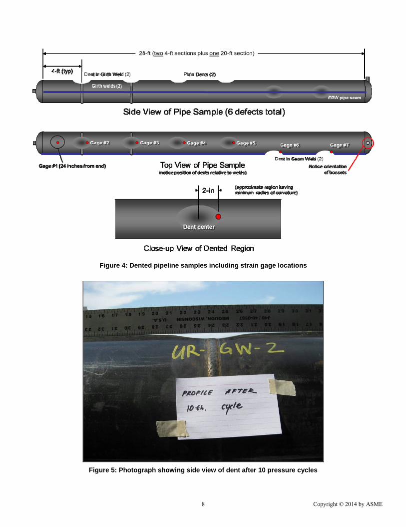
The participating composite repair systems were used to repair specific dent configurations installed in 12.75-inch x 0.188-inch, Grade X42 pipe ERW material. The dent geometries included plain dents, dents in girth welds, and dents in seam welds. The dents were installed to a depth of 15% of the pipe’s outer diameter (1.91 inches) using an NPS 4 end-cap indenter held in place while the pipe sample was pressurized to 72% SMYS, or 892 psi. After all aspects of the denting process were completed, strain gages were positioned near the dents, after which the composite repair systems were installed on the outside surface of the pipe at a pressure of 0 psi. Figure 4 is a schematic diagram showing the configuration for each pipe sample, while Figure 5 is a photograph showing the side profile of the dent.
Each manufacturer was responsible for its design and for performing installations. All repairs included a filler material, also known as the load transfer material, which was used to fill the dented region of the pipe before the composite material was installed. In this program, composite fiber materials included E-glass and carbon. One system utilized high-strength steel wound around the circumference of the pipe, and bonded with a resin. Matrix resins included two-part epoxies and water-activated urethanes in a pre-impregnated, or pre-cured, form. In this case, the binding component in the composite repair system was applied to the cloth and allowed to partially cure. This is sometimes referred to as a “pre-preg.”
Each composite repair system was evaluated using a total of six dents, except one system that was only used to repair two plain dents. The six dents in each pipe sample were pressure cycled to failure or 250,000 cycles (whichever occurred first) at a pressure range of approximately 100 psi to 992 psi. These pressure values are referred
to in this report as having a range equal to 72% of the pressure imposing the specified minimum yield strength (SMYS) in the hoop direction, varying from 100 psi, or 8% SMYS to 992 psi, or 80% SMYS.
Of the 11 tested systems, six products used to repair plain dents were able to achieve the 250,000 cycle run-out condition as shown in Figure 6. Some samples ran for more than 250,000 cycles, since the shut-off condition in the cyclic pump was not automated. One repair system was cycled beyond the run-out condition to determine the actual limit state of the pipe, which resulted in a fatigue failure of the ERW seam in the base pipe (outside of the repairs) at 358,470 cycles.
As observed in other composite repair studies, the effectiveness of a composite repair is directly proportional to the level of reinforcement provided to the damaged pipe material. In this particular study, those systems that were most effective were able to significantly reduce strains in the dented regions of the pipe samples. Table 3 lists strain ranges for each of the repair systems in reinforcing plain dents. In this table, Product H was Armor Plate® Pipe Wrap, which was able to reduce strain in the unreinforced plain dent by a factor of 6.3 (i.e., 4,537 / 723 με). DISCUSSION While the vast majority of work associated with composite reinforcement of pressurized piping and pipelines has involved experimental investigations, some numerical modeling work has been conducted. It is the author’s observations that the role of numerical modeling in optimizing composite reinforcement will play a larger role in the design of future repairs. In terms of information available in the open literature, a body of work completed by Alexander et al presented at OMAE 2008 provides details findings from a study involving the design and optimization of a carbon-epoxy system using finite element analysis (FEA) and full-scale destructive testing.
Using the same composite repair optimization approach, a recent study evaluated the reinforcement of pipe fittings using E-glass epoxy composite materials. This work involved optimization of the composite design using elastic-plastic FEA, in conjunction with full-scale testing. The optimization involved variations in composite thickness and fiber orientation. Experimental strain measurements beneath the composite reinforcement were correlated with finite element analysis results. Several figures are included from this recent analysis work and are listed below: Figure 7: Finite element model showing composite
reinforcement Figure 8: Architecture of two different competing composite
The work as shown in these figures is a good representation of the type of numerical modeling that can be conducted to study the ability of composite materials to reinforce damaged piping and pipelines. Of particular interest is the magnitude of reinforcement provided by the composite material to the reinforced steel. The calculated stresses in the composite material should be compared to allowable design stresses based on the governing composite repair codes. The stresses (and strains) in the reinforced steel should be carefully evaluated to ensure that the repair achieves the intended design conditions, including cyclic service, if applicable.
CLOSING COMMENTS The paper was prepared to provide industry with a resource for
evaluating the design of composite repair technology based on numerous programs conducted for the pipeline industry. The resources included in this document represent a significant body of work completed over the past 20 years focused on understanding the mechanics and materials of composite repair technology. The insights gained in completing these studies have been used to establish the technical foundation for repairing a wide range of anomalies and features in high-pressure gas and liquid pipelines.
The foundation for using composite repair systems to reinforce high pressure pipelines is built on two cornerstones. The first is a good design basis, preferably in accordance with the ASME PPC-2 composite repair standard. The design integrates material properties for the system in question to establish the repair dimensions (i.e., thickness and length), as well as establishing the limitations for the repair considering factors such as operating temperature and cyclic pressure conditions. The second cornerstone is validation of the design itself via destructive testing. Because of the multiple components involved in every composite repair system (i.e., fiber, polymer matrix, and load transfer filler material), it is essential that the interdependent behavior of the components be evaluated simultaneously. Some of the early composite repair research failed to take this interdependency into account. Of particular importance when considering composite installations in plant environments includes accounting for environmental and operational factors such as exposure to chemicals and operating at elevated temperatures.
This document is useful in providing the reader with an overall understanding of the composite repair technology’s state of the art, while at the same time providing a detailed explanation of the design basis for modern composite repair technologies. In moving beyond conventional uses for repairing and reinforcing pipelines, such as the reinforcement of corrosion and dents, the foundational elements provided in this report can be used to evaluate future applications. REFERENCES 1. American Society of Mechanical Engineers, Liquid
Transportation System for Hydrocarbons, Liquid Petroleum Gas, Anhydrous Ammonia and Alcohols, ASME B31.4, New York, New York, 2003 edition.
2. American Society of Mechanical Engineers, Gas Transmission and Distribution Piping Systems, ASME B31.8, New York, New York, 2003 edition.
3. American Society of Mechanical Engineers, Manual for Determining the Remaining Strength of Corroded Pipelines, ASME B31G-1991, New York, New York, 1991 edition.
4. Pipeline Safety: Gas and Hazardous Liquid Pipeline Repair, Federal Register, Vol. 64, No. 239, Tuesday, December 14, 1999, Rules and Regulations, Department of Transportation, Research and Special Programs Administration, Docket No. RSPA-98-4733; Amdt. 192-88; 195-68 (Effective date: January 13, 2000).
5. STP-PT-005 2006, Design Factor Guidelines for High-Pressure Composite Hydrogen Tanks, American Society of Mechanical Engineers, New York, New York, 2006.
6. ASTM D2992, Standard Practice for Obtaining Hydrostatic or Pressure Design Basis for Fiberglass (Glass-Fiber-Reinforced Thermosetting-Resin) Pipe and Fittings, ASTM International, 2001.
7. ANSI/ASME PCC-2-2011, Repair of Pressure Equipment and Piping, Repair Standard, Article 4.1, Non-metallic Composite Repair Systems for Pipelines and Pipework: High Risk Applications, American Society of Mechanical Engineers, New York, 2011.
8. American Society of Mechanical Engineers, ASME Boiler and Pressure Vessel Code, Section VIII, Division 3: Alternative Rules for Construction of High Pressure Vessels, New York, New York, 2004 edition.
9. Alexander, C., and Bedoya, J., Repair of Dents Subjected to Cyclic Pressure Service Using Composite Materials, Proceedings of IPC2010 (Paper No. IPC2010-31524), 8th International Pipeline Conference, September 27–October 1, 2010, Calgary, Alberta, Canada.
10. Alexander, C.R., Evaluating the Use of Composite Materials in Reinforcing Offshore Risers Using Full-scale Testing Methods, Paper No. IOPF2007-104, Proceedings of the ASME International Offshore Pipeline Forum, October 23–24, 2007, Houston, Texas.
11. Alexander, C., Cercone, L., and Lockwood, J., (June 2008), "Development of a Carbon-Fiber Composite Repair System for Offshore Risers," Paper No. OMAE2008-57599, The 27th International Conference on Offshore Mechanics and Arctic Engineering, June 15-20, 2008, Estoril, Portugal.
Figure 2: Hoop Strain at 72% SMYS per radial position for System #1 (Hoop stress calculated as the product of measured strain and the composite’s elastic modulus)
Figure 3: Hoop Strain at 72% SMYS per radial position for System #2 (Hoop stress calculated as the product of measured strain and the composite’s elastic modulus)
Figure 8: Architecture of two different competing composite reinforcement configurations
Figure 9: FEA model contour plots showing pressures required to induce yielding (Note that the presence of the composite increases the pressure at which yielding occurs, stress units of psi)