Phil. Trans. R. Soc. A (2012) 370, 1850–1870doi:10.1098/rsta.2011.0441
The role of delamination in failure offibre-reinforced composites
BY M. R. WISNOM*
Advanced Composites Centre for Innovation and Science, University of Bristol,University Walk, Bristol BS8 1TR, UK
The mechanisms by which delamination contributes to the failure of fibre-reinforcedcomposites are reviewed. Through-thickness failure owing to interlaminar stresses isconsidered first, and the effect of delamination in impact and compression after impact.The way in which in-plane failure can occur by delamination and matrix cracks joiningup to produce a fracture surface without the need to break fibres is considered next.Examples of quasi-isotropic laminates loaded at different off-axis angles, and withdifferent numbers and thicknesses of ply blocks show large differences in unnotched tensilestrength controlled by delamination from the free edge. Similar mechanisms determinethe strength of notched specimens and give rise to the hole size effect, whereby tensilestrength increases with decreasing hole diameter owing to increased delamination andsplitting. Open hole tension and over-height compact tension tests with constant in-plane dimensions show a transition in failure mode with increasing ply block thicknessfrom fibre-dominated fracture to complete delamination. In all these cases, the criticalfactor controlling strength is the relative propensity to delaminate.
Delamination is a critical failure mechanism in laminated fibre-reinforced polymermatrix composites, and is one of the key factors differentiating their behaviourfrom that of metallic structures. It is caused by high interlaminar stressesin conjunction with the typically very low through-thickness strength. Thephenomenon arises because fibres lying in the plane of a laminate do not providereinforcement through the thickness, and so the composite relies on the relativelyweak matrix to carry loads in that direction. This is compounded by the fact thatmatrix resins are typically quite brittle.
A lot of research has been carried out on delamination owing to through-thickness stresses, but it is less widely appreciated that delamination also hasa crucial role in determining in-plane strength, frequently leading to prematureinitiation of failure. In-plane failure of composites is driven by the energy releasedas fibres are unloaded. This can occur in two ways: by fracture of the fibres,*[email protected]
One contribution of 15 to a Theme Issue ‘Geometry and mechanics of layered structures andmaterials’.
Figure 1. Schematic of pull-out failure of (45/−45)s laminate with no fibre fracture.
or by delamination and matrix cracks joining up to produce a fracture surfacewithout the need to break fibres. The latter mechanism is illustrated in figure 1,which shows schematically a (45/−45)s laminate that has failed in tension bypull-out without any fibre failure. A similar phenomenon can also affect failurein other layups, and is especially important at stress concentrations such asnotches. Damage at such features is controlled by delamination and associatedsplitting that leads to blunting of the notch, which has a large effect on strength.Delamination also has a critical role in the behaviour of composites under impact,affecting both the damage caused under impact loading, and the subsequentresponse in compression after impact.
This paper reviews the ways in which delamination contributes to the failureof fibre-reinforced composites. Through-thickness failure is considered first, whichmay occur owing to out-of-plane loading, the geometry of the structure ordiscontinuities such as cracks, ply drops or free edges. The effect of delaminationon impact and compression after impact is considered briefly. The mechanismsby which delamination may affect in-plane strength are then discussed, firstfor unnotched laminates, and then for cases with holes or cracks. Bringingtogether experimental evidence from a range of different cases contributes newinsights into the factors controlling failure of composites and the crucial roleof delamination.
2. Through-thickness failure
Delamination may lead directly to through-thickness failure owing to interlaminarstresses. To understand this mechanism, it is helpful to distinguish betweenoverall interlaminar stresses that arise owing to the loading and geometry ofa component, and highly localized interlaminar stresses that arise owing to someform of discontinuity, and may be associated with stress singularities. These caseswill be discussed separately, although in practice, they may occur together andcombine to initiate failure.
Phil. Trans. R. Soc. A (2012)
on May 22, 2018http://rsta.royalsocietypublishing.org/Downloaded from
Figure 2. Features prone to delamination owing to through-thickness loading. (a) Lug fitting;(b) rib-to-skin joint.
(a) (b)
Figure 3. Features prone to delamination owing to geometry. (a) Taper; (b) curved section inbending.
(a) Overall interlaminar stresses owing to out-of-plane loading
Figure 2 shows two examples of situations where out-of-plane loading mayinitiate failure owing to overall interlaminar stresses. The first is a loading fixturesuch as might be used to attach a rigging wire to a composite yacht mast. Thisproduces primarily interlaminar shear stresses, but tensile stresses also arise if afitting is embedded within the laminate or bonded on the outer surface. A similarsituation arises where a bolt through a composite plate is subject to axial loading.
The second case is a connection between plates in a built-up structure, e.g.an aircraft wing skin to rib web joint. Here, the connection may need to resistout-of-plane loads, such as those arising in a wingbox owing to fuel pressureloading. This can cause interlaminar tensile stresses as well as shear. Even if thereare no externally applied out-of-plane loads, secondary loading in the through-thickness direction may arise in a built-up structure as a result of constraintsbetween different parts, and the way the overall loads are carried through thestructure. Considerable research has been undertaken on such failure mechanisms,for example, using simple T-pieces to study the way that damage initiates andgrows [1,2].
Another important example of out-of-plane loading is impact caused byincidents such as dropped tools, stones picked up by tyres or birdstrikes.This produces through-thickness shear combined with compression, and will bediscussed in §3.
(b) Overall interlaminar stresses owing to geometry
Overall interlaminar stresses can also be produced indirectly as a result of thegeometry of the structure, as shown in the examples in figure 3. The first case is atapered composite in which interlaminar shear and normal stresses are generatedas the in-plane load diffuses with the change in thickness.
The second case is bending of curved laminates, which generates interlaminarnormal stresses [3]. These will be tensile if the moment is tending to reduce thecurvature as shown in the figure, and become more significant as the ratio of
Phil. Trans. R. Soc. A (2012)
on May 22, 2018http://rsta.royalsocietypublishing.org/Downloaded from
Figure 4. Features prone to delamination owing to discontinuities. (a) Ply drop; (b) free edge.
thickness to radius increases. Bending can occur even with only in-plane loadingas a result of the component geometry, e.g. owing to offset loads. This mechanismis also important at joints in structures, which frequently have corner radii. Forexample, in the case shown in figure 2b, there would be additional interlaminarstresses owing to the curved geometry as well as those arising directly as a result ofthe out-of-plane loading. Similarly, bending can arise in built-up structures withcurved flanges owing to tolerancing issues when different parts are assembled.
Bending will also arise in curved composites owing to temperature changes asa result of the difference in expansion coefficients in the plane and through thethickness of the composite [3]. This will produce interlaminar normal stresses ifthe laminate is not free to deform. The same phenomenon also causes residualstresses in manufacturing during the cooldown from the cure temperature to roomtemperature [4]. Resin shrinkage during cure is another mechanism that can causedistortion and interlaminar residual stresses [5], which may lead to delamination.
Features such as joggles will also cause interlaminar stresses owing to curvedfibre paths, offsets in load paths through the thickness and interaction betweenthe part and tooling causing residual stresses during cure [6].
(c) Localized interlaminar stresses
Very high interlaminar stresses can arise locally at geometrical or materialdiscontinuities, and these may cause failure even though the overall stress levelis not unduly high. Figure 4 shows features in composites that give rise to thissituation. Sharp discontinuities cause singularities, with the stresses theoreticallybecoming infinite as the point of discontinuity is approached and failure willpropagate if there is sufficient energy available to drive it.
Cracks are the most obvious form of discontinuity, such as initial delaminationsarising during manufacture, or produced in service by events such as impacts.Transverse ply cracks may also develop owing to residual stresses or machiningdamage during manufacture, or under service loads. These cracks produce highlocalized stresses where they meet plies of different orientations, which may causedelamination at the ply interfaces [7].
Cut or discontinuous plies caused by ply joins or changes of ply materialor orientation within the layup produce discontinuities analogous to transversecracks. These are particularly severe if the cut is perpendicular to the fibredirection in which the major loads are carried, and can be a serious source ofdelamination [8]. Ply drop-offs used to taper the thickness of composites as shownin figure 4a are another feature prone to delamination [9]. This is driven largelyby the discontinuities owing to the terminating plies, with thick blocks of pliesand drops on the surface being particularly susceptible.
Phil. Trans. R. Soc. A (2012)
on May 22, 2018http://rsta.royalsocietypublishing.org/Downloaded from
A similar situation to a surface ply drop arises at a larger scale in joints. Forexample, there is a discontinuity where a flange attaches to a skin, as shown infigure 2b. This produces localized stresses even under in-plane loading that maycause debonding at the interface, or delamination within the laminates. The samesituation arises whether the joint is co-cured or bonded. Delamination is especiallylikely in co-bonded or secondary-bonded joints as the adhesive typically has ahigher toughness than the matrix resin, driving the failure into the composite.Structural features such as stringer terminations produce similar discontinuitiesat an even larger scale [10].
Free edges are another important cause of interlaminar stresses [11]. Thematerial discontinuities owing to the different ply orientations cause stresssingularities. Interlaminar normal and shear stresses are produced at free edgeswhere there are differences in Poisson’s ratio between plies owing to differentply orientations, as in the cross-ply laminate shown in figure 4b. Discontinuitiesbetween different materials in the same laminate can produce similar effects.Interlaminar shear stresses arise where off-axis plies reach the edge because thein-plane shear stress must vanish at the free surface. These can also producenormal stresses owing to the offsets between plies in the thickness direction. Suchstresses can be a major source of delamination, especially when several plies ofthe same orientation are stacked together [12].
(d) Combined overall and localized interlaminar stresses
In practice, overall and localized interlaminar stresses often arise together. Forexample, a tapered laminate (as shown in figure 3a) will usually be manufacturedby dropping off plies, producing discontinuities such as that shown in figure 4aand giving rise to localized stresses in addition to the overall stresses owing to thegeometry. Similarly, the flange connection (shown in figure 2b) has a discontinuityproducing localized stresses in addition to the overall stresses owing to the pull-offloading. Free edges or cracks in areas of overall interlaminar stress will also leadto interaction between the discontinuity and overall stresses. In such cases, thestress fields will interact, causing delamination earlier than if only the localized oroverall stress field were present on its own [13,14]. Similar behaviour and failuremechanisms have also been observed under fatigue loading [15].
3. Impact and compression after impact
(a) Delamination under impact
Delamination is a critical damage mode under impact loading. It is particularlyinsidious because it can have a large effect on residual strength, yet theremay be little or no indication of damage on the surface, despite extensiveinternal delamination, as shown in the edge view of an impacted quasi-isotropicglass–epoxy specimen in figure 5 [16]. C-scans reveal a characteristic pattern ofdelaminations as shown in another typical case for a quasi-isotropic carbon–epoxylaminate (figure 6) [17].
There are two mechanisms driving the delamination. Firstly, there isinterlaminar shear as a result of the contact force. This causes a maximum stressnear the mid-plane reducing away from the impact point. A delamination at
Phil. Trans. R. Soc. A (2012)
on May 22, 2018http://rsta.royalsocietypublishing.org/Downloaded from
Figure 5. Edge view of impacted specimen showing extensive delamination but no surfacedamage [16].
50 mm
1 : 0/45
2 : 45/90
3 : 90/–45 4 : –45/90
5 : 90/45
impacted side
6 : 45/0
90°experiment : 25 J/1950 mm2
45°
–45°
0°
Figure 6. C-scan of impacted specimen showing typical pattern of delaminations [17]. (Onlineversion in colour.)
the mid-plane causes a large reduction in bending stiffness, giving a significantenergy-release rate. It has been shown that for an axisymmetric case with apoint load in a homogeneous quasi-isotropic laminate, the energy-release rate isin fact constant with delamination size, and based on this, a threshold impactforce for delamination has been proposed [18]. The energy-release rate increaseswith increasing number of delaminations [19], promoting further delaminations toform once the first one has initiated. Right under the impact point delaminationtends to be suppressed due to the effect of through-thickness compressive stresses,which increase both the interlaminar shear strength and fracture toughness [20].
The second mechanism is delaminations propagating from transverse tensilecracks that tend to form towards the back surface of the laminate owing tobending [21]. This is particularly important in thin composites where bendingdeformation dominates, whereas in thicker laminates shear is more important.In practice, both mechanisms occur, and the multiple delaminations throughthe thickness link up via transverse cracks, forming a spiral staircase patternof delaminations between transverse cracks in adjacent plies [21,22], as alsoseen in figure 6. These matrix cracks have a significant effect on the shape ofthe individual delaminations, which tend to be elongated along the directionof the crack [21].
The mechanisms of damage under impact loading can be well simulated usingcohesive elements to model the delamination between plies and transverse crackswithin the plies [23]. This is able to reproduce the patterns of damage observed
Phil. Trans. R. Soc. A (2012)
on May 22, 2018http://rsta.royalsocietypublishing.org/Downloaded from
experimentally, including the lack of delamination under the impactor, providedthe compression enhancement to interlaminar shear is accounted for. It has alsobeen shown that similar damage and failure loads are obtained even if thematrix cracks are not modelled, suggesting that these are in fact of secondaryimportance [23]. Ignoring the cracks may, however, affect the predicted shape ofthe delaminations.
Fibre failure usually occurs after delamination [23] and so ignoring it in themodel still gives good predictions of initial impact damage. However, becausedelamination reduces the bending stiffness and allows greater deformation tooccur, it also has a beneficial effect in limiting the stresses that lead to fibrefailure. If it was suppressed completely, then there would be a risk of prematurefibre failure, which could lead to a more brittle overall response.
(b) Effect of delamination on residual strength
Delamination damage under impact loading has relatively little effect onresidual tensile strength, but can dramatically reduce the compressive strengthafter impact [24]. This leads to the need to design structures to withstand barelyvisible impact damage, which is one of the most severe constraints on usingcomposites in highly loaded applications.
Measurement of out-of-plane displacements and strain fields during loadingindicates a progressive local buckling of the delaminated plies until final collapseprecipitated by unstable propagation of delamination [22]. The mechanism is wellillustrated by the detailed results of finite-element simulations with simplifiedcircular delaminations [25] and more realistic spiral patterns of delaminationslinked by transverse cracks [26]. Propagation of damage under compressiveloading was modelled using cohesive elements. The results showed early bucklingof the surface sublaminate followed by buckling of all the sublaminates together,either in a symmetric or asymmetric pattern. At higher loads, there wasinteraction with overall buckling, and a critical point was reached when thedelaminations started to propagate, which corresponded to the peak load. Thedelamination fracture toughness had a significant effect on the maximum load.These results show the crucial effect that delamination has on compressivestrength after impact. Compressive fibre fracture as a result of the loadredistribution caused by the buckled plies is an alternative mechanism [27]. Hereagain, the delamination is crucial in allowing buckling to occur.
Delamination is also important in compression fatigue. Butler et al. [28]have suggested that the fatigue limit for specimens with barely visible impactdamage corresponds to the point when damage can grow by propagation ofdelamination from the buckled sublaminates. A simple model was proposed thatcould predict the compression fatigue strain limit based on the energy-releaserate for propagation of the critical delamination.
4. Unnotched in-plane failure
The effect of delamination producing failure owing to through-thickness stresses iswell known. However, the role of delamination in in-plane failure is also extremelyimportant, but has received much less attention. Composites will find the lowestenergy route to shedding load, and sometimes this occurs by delamination and
Phil. Trans. R. Soc. A (2012)
on May 22, 2018http://rsta.royalsocietypublishing.org/Downloaded from
Figure 7. Effect of loading angle on unnotched quasi-isotropic tensile strength. (Online versionin colour.)
splitting rather than fibre fracture, as shown schematically in figure 1 for an angle-ply laminate. The importance of this mechanism is shown by two different casesof simple unnotched in-plane tension tests on quasi-isotropic laminates: firstlywith loading at different off-axis angles, and secondly with different thicknesses.
(a) Effect of off-axis loading on unnotched tensile strength
Sun & Zhou carried out tests on quasi-isotropic laminates of AS4/3501-6graphite/epoxy loaded at different off-axis angles. While the stiffness wasunaffected, there was a dramatic reduction in strength, as shown in figure 7 forlayup (0/90/45/−45)s with polished edges [29]. This occurred owing to splits inthe off-axis plies that ran from the free edge and joined up via delaminationto form a characteristic staircase pattern, providing a fracture path withoutnecessarily involving fibre fracture. This is illustrated in figure 8, a radiographtaken before ultimate failure of a specimen loaded at an off-axis angle of 22.5◦.
(b) Effect of thickness on unnotched tensile strength
Even when there are continuous fibres in the loading direction, unloadingof off-axis plies can still initiate premature failure. This mechanism is wellillustrated by a series of tests carried out on quasi-isotropic laminates of differentthicknesses, which showed substantial reductions in unnotched tensile strengthcontrolled by delamination [30]. IM7/8552 carbon–epoxy laminates with layup(45m/90m/−45m/0m)ns) were tested. With m = 1, n was varied from 1 to 4, givinglaminates from 1 to 4 mm thick with dispersed plies. Keeping n = 1 and increasingm from 2 to 8 gave laminates from 2 to 8 mm thick with a single set of repeatingplies with different ply block thicknesses. The smallest specimens were 1 mmthick, 8 mm wide, with a gauge section of 30 mm and bonded glass–epoxy endtabs. Thicker specimens had the in-plane dimensions increased in proportion tothe thickness so that they were fully scaled.
Phil. Trans. R. Soc. A (2012)
on May 22, 2018http://rsta.royalsocietypublishing.org/Downloaded from
The expected failure stress was calculated using laminated plate theory withthe properties shown in table 1, and the unidirectional tensile strength of2806 MPa measured with a small tapered thickness specimen with chamferedplies [30]. This gave a quasi-isotropic strength of 1077 MPa.
Experimental results are summarized in table 2, and plotted in figure 9. Thereare large differences between different layups and none of them reached theexpected strength. This is due to initiation of delamination at the free edge,which could clearly be seen in the 2 mm thick specimens with blocked plies(figure 10a). Subsequently, the fibres also break, but the initial failure is controlledby delamination. When more plies are blocked together, delamination occursat even lower stresses and becomes the main failure mechanism, stepping downthrough the plies until complete separation occurs at the −45/0 interface prior tofibre failure, producing the final fracture seen in figure 10c. The same mechanismis believed to control the strength of the dispersed ply specimens, with initiation
Phil. Trans. R. Soc. A (2012)
on May 22, 2018http://rsta.royalsocietypublishing.org/Downloaded from
of free edge delamination leading straight away to fibre failure. In this case, thestrength actually increases with thickness, because the multiple sublaminatesinhibit the free edge delamination initiating at the surface plies from propagating.
Phil. Trans. R. Soc. A (2012)
on May 22, 2018http://rsta.royalsocietypublishing.org/Downloaded from
Figure 11. Schematic of pull-out in notched quasi-isotropic laminate. (Online version in colour.)
Laminated plate theory gives the same expected strength for all these cases.The large variation in strengths which are all below this value is due tothe differences in delamination behaviour of the different laminates. This isparticularly striking because the stacking sequence was selected to minimize therisk of edge delamination after analysis of all 12 possible symmetric quasi-isotropicstacking sequences with eight plies by finite-element strain energy-release ratecalculations [31].
5. Notched in-plane failure
(a) Delamination failure in open hole tension
Delamination and the stress at which it occurs relative to fibre failure aresimilarly important in notched strength. For example, in open hole tension of(45/90/−45/0)s laminates with thick ply blocks, delamination and pull-out canoccur, leaving two ligaments of unidirectional material as shown in figure 11.
This mechanism is shown in a series of scaled specimens of the same materialand stacking sequence as the unnotched ones presented in the previous section[32]. Specimens with a centrally located circular hole were tested in tensionwith constant width-to-hole diameter (W /D) and length-to-hole diameter (L/D)ratios, as shown in figure 12.
Results of 4 mm thick specimens with blocked plies are plotted in figure 13,with a log scale to better cover the wide range of hole sizes from 1.6 to 50.4 mm.All failures were controlled by delamination, and there was a considerablevariation in strength with specimen size. There is a clear trend with the strengthstransitioning between a lower and a higher asymptote as the hole size increases.Triangular delaminations similar to those observed in the unnotched specimensformed at the intersection of the surface 45◦ ply and the free edges, and grewgradually across the width between the hole and straight edge in both directions.
Phil. Trans. R. Soc. A (2012)
on May 22, 2018http://rsta.royalsocietypublishing.org/Downloaded from
Figure 13. Effect of hole size on delamination stress of (454/904/−454/04)s) laminates (diamonds,notched; blue line, unnotched W = 32 mm; dashed line, unnotched W = 4 mm; red curve, fit).(Online version in colour.)
The point at which these span the complete width of the specimen correspondsto the point when the delamination is able to step down through the remainingplies to the −45/0 interface and propagate along the whole length.
Comparing these results with the previous unnotched tests on specimens 32 mmwide with the same layup and similar damage development shows that theunnotched case fits well as an asymptote at large hole sizes (figure 13). The size ofthe triangular delaminations at the free edges is related to the ply block thickness.It might, therefore, be expected that if the specimen was very narrow, then thesewould be able to join up across the complete width more easily, leading to earlieronset of full delamination. To test this hypothesis, unnotched specimens of thesame layup with a width of only 4 mm were tested in tension. These delaminatedin a similar way, but at an average stress of only 266 MPa. This is also shown asa line in figure 13, and fits well as a lower asymptote.
The notched strength of these specimens is, therefore, controlled by how easilydelamination can occur. This depends on two main factors: the absolute ply blockthickness that controls the total amount of energy available to drive delamination,and the ratio of ply block thickness to distance from the free edge that affectshow easily it can propagate across the width. If the specimens are normalized insuch a way as to account for the different propensity to delaminate and plottedagainst ligament width rather than hole size, then we can account for a wholerange of different cases on a single plot. The normalization is based on the amount
Phil. Trans. R. Soc. A (2012)
on May 22, 2018http://rsta.royalsocietypublishing.org/Downloaded from
Figure 14. Effect of ply block thickness and ligament width on delamination of (45m/90m/−45m/0m)s) laminates (diamonds: m = 4, Tply = 0.5 mm; blue line: unnotched W = 32 mm;dashed line: unnotched W = 4 mm; red curve: fit; squares: m = 8, Tply = 1 mm; triangle: m = 2,Tply = 0.25 mm; pluses: m = 2, varying W /D). (Online version in colour.)
of available energy, which is proportional to the ply block thickness and the stresssquared. The corrected failure stress for a ply block thickness Tply compared withthat of the baseline 0.5 mm specimens shown in figure 13 is given by
s̄ = s
√Tply
0.5. (5.1)
Results are plotted in figure 14 for open hole specimens with thinner andthicker ply blocks, and also for another set of tests on the same materialwhere a W /D ratio of 10 was used as well as 5. All these specimens failed bydelamination. A finite width correction was applied to the W /D = 10 resultsto ensure direct comparability. The results all fit reasonably well the trendshown earlier, confirming the parameters controlling tensile strength of open holespecimens failing by delamination.
(b) Role of delamination in fibre-dominated open hole tension failure
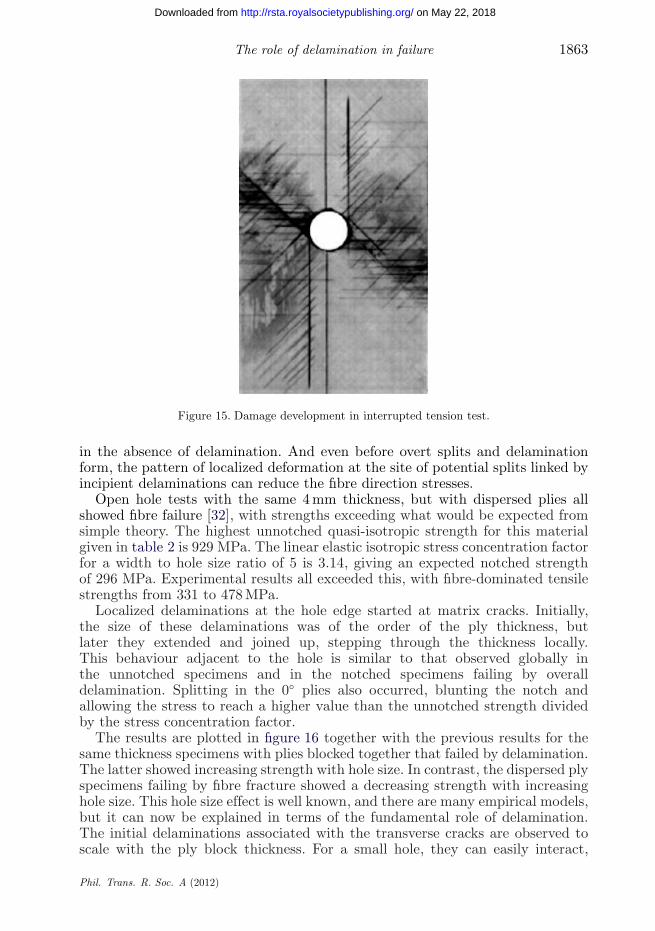
The same type of splitting and delamination damage mechanisms initiatingfrom the free edges as in the unnotched case are seen in figure 15. This X-raywas taken from an interrupted test on a (454/904/−454/04)s) laminate witha 3.175 mm hole [33], showing how damage develops before the final pull-outillustrated schematically in figure 11.
With thinner, dispersed plies, fibre fracture occurs, but delamination still hasa very important effect. It allows splits to develop, leading to blunting of thenotch before reaching the stress for overall delamination, and resulting in anincrease in the fibre-dominated tensile strength. This was shown for sharp-notchedtension specimens by Kortschot & Beaumont [34]. Analogous behaviour was alsodemonstrated under fatigue loading by Spearing & Beaumont [35]. A similarmechanism applies for the open hole tension specimens considered here. Althoughit is primarily the splits that reduce the stress concentration, these cannot occur
Phil. Trans. R. Soc. A (2012)
on May 22, 2018http://rsta.royalsocietypublishing.org/Downloaded from
Figure 15. Damage development in interrupted tension test.
in the absence of delamination. And even before overt splits and delaminationform, the pattern of localized deformation at the site of potential splits linked byincipient delaminations can reduce the fibre direction stresses.
Open hole tests with the same 4 mm thickness, but with dispersed plies allshowed fibre failure [32], with strengths exceeding what would be expected fromsimple theory. The highest unnotched quasi-isotropic strength for this materialgiven in table 2 is 929 MPa. The linear elastic isotropic stress concentration factorfor a width to hole size ratio of 5 is 3.14, giving an expected notched strengthof 296 MPa. Experimental results all exceeded this, with fibre-dominated tensilestrengths from 331 to 478 MPa.
Localized delaminations at the hole edge started at matrix cracks. Initially,the size of these delaminations was of the order of the ply thickness, butlater they extended and joined up, stepping through the thickness locally.This behaviour adjacent to the hole is similar to that observed globally inthe unnotched specimens and in the notched specimens failing by overalldelamination. Splitting in the 0◦ plies also occurred, blunting the notch andallowing the stress to reach a higher value than the unnotched strength dividedby the stress concentration factor.
The results are plotted in figure 16 together with the previous results for thesame thickness specimens with plies blocked together that failed by delamination.The latter showed increasing strength with hole size. In contrast, the dispersed plyspecimens failing by fibre fracture showed a decreasing strength with increasinghole size. This hole size effect is well known, and there are many empirical models,but it can now be explained in terms of the fundamental role of delamination.The initial delaminations associated with the transverse cracks are observed toscale with the ply block thickness. For a small hole, they can easily interact,
Phil. Trans. R. Soc. A (2012)
on May 22, 2018http://rsta.royalsocietypublishing.org/Downloaded from
Figure 16. Open hole tensile strength of 4 mm thick quasi-isotropic specimens (squares and bluecurve: dispersed plies, fibre failure; diamonds and red curve: blocked plies, delamination). (Onlineversion in colour.)
Figure 17. Delaminations from ply cracks can join up more easily for small holes.
facilitating damage linking up through the thickness and propagating, as shownschematically in figure 17 for just the 45◦ cracks. As the hole size to ply blockthickness ratio increases, it becomes more difficult for the delaminations at thehole edge to join up and allow splitting to occur, causing a reduction in strengthwith increasing size as damage is inhibited [32].
(c) Transition in failure mode with ply block thickness in open hole tension
A further example will illustrate the effect of increasing delamination oninhibiting fibre failure and leading to a switch in failure mode. Open hole tensionstrengths for specimens with a constant 25.4 mm diameter hole, but different plyblock thicknesses are compared [36]. Specimens had the same stacking sequenceand same in-plane dimensions, with a gauge length of 512 mm and width of128 mm. The first three layups were (45/90/−45/0)4s), (452/902/−452/02)2s) and
Phil. Trans. R. Soc. A (2012)
on May 22, 2018http://rsta.royalsocietypublishing.org/Downloaded from
Figure 18. Transition in failure mode for open hole tension specimens. (Online version in colour.)
(454/904/−454/04)s), all 4 mm thick. The fourth layup is (458/908/−458/08)s),and the overall thickness is now 8 mm, the minimum possible for this number ofplies blocked together.
Figure 18 shows the tensile strength as a function of the ply block thickness.The specimens with thinner ply blocks failed by fibre fracture, and there was a26 per cent increase in strength from 331 MPa for the single dispersed ply caseup to 417 MPa for the case with four plies blocked together. The specimens witheight blocked plies failed by complete delamination at the −45/0◦ ply interfacebefore fibre fracture, with an average strength of only 232 MPa. The specimenswith four plies blocked together showed a mixed failure mechanism, with two ofthe six tests exhibiting fibre-dominated failure, and four showing delamination.They are, therefore, at the transition between the fibre failure mode seen for thespecimens with thinner ply blocks, and delamination seen with very thick blocks.
These results again confirm the importance of delamination on in-planestrength. As the amount of delamination increases, the notched strength increasesuntil the point where the failure mode changes from fibre-dominated to completedelamination, with the highest strength occurring at the transition.
Delamination has also been shown to be important in open hole compressiontests when the ply block thickness is increased [37]. Higher strengthswere obtained with blocked rather than dispersed plies, because significantdelamination occurred, allowing splits to develop, blunt the stress concentrationand inhibit microbuckling.
(d) Tensile failure at sharp notches
Delamination has been shown to be similarly important for in-plane failure inover-height compact tension specimens with a sharp notch through the completethickness. Tests were carried out on the same IM7/8552 material and stackingsequence as for the open hole tests, with the geometry shown in figure 19 [38].Specimens were 2 mm thick, with either dispersed single plies or plies blockedtogether in pairs. Layups were (45/90/−45/0)2s) and (452/902/−452/02)s). Thelatter specimens showed much more delamination at the notch, as seen in
Phil. Trans. R. Soc. A (2012)
on May 22, 2018http://rsta.royalsocietypublishing.org/Downloaded from
Figure 19. Geometry of over-height compact tension test specimens.
the C-scans in figure 20 from tests interrupted at approximately the same stagein the load–displacement curve, i.e. just before any major load drop. Thesespecimens showed a 75 per cent increase in maximum load because of the splittingaccompanying the delamination, which blunted the notch. When the number ofplies blocked together was further increased to four, there was a transition infailure mode to complete delamination, with a block of 0◦ plies at the notchpulling out completely over the whole length of the specimen, but with no fibrefracture, as shown in figure 21. The thickness for this latter case with layup(454/904/−454/04)s) is 4 mm, so results are presented in terms of load per unitthickness. As for the open hole specimens, this transition in failure mode wasassociated with a drop in strength (figure 22).
6. Conclusions
Delamination is a critical failure mode in fibre-reinforced composites. It may leaddirectly to through-thickness failure owing to interlaminar stresses caused by out-of-plane loading, curved or tapered geometry, or discontinuities owing to cracks,ply drops or free edges. Impact loading causes multiple delaminations, which canpropagate in conjunction with sublaminate buckling, greatly reducing the residualcompressive strength.
Delamination also has a crucial role for in-plane failure by allowing transversematrix cracks to join up and produce a fracture surface, shedding load withoutfibres breaking. This has been illustrated by results of quasi-isotropic laminatesloaded in tension at an off-axis angle, where a characteristic pattern of damageinitiating from the edges causes large reductions in in-plane strength. Evenwhere there are continuous fibres in the loading direction, delamination can stillproduce large reductions in strength, especially when plies of the same orientationare blocked together. Unnotched quasi-isotropic specimens with different ply
Phil. Trans. R. Soc. A (2012)
on May 22, 2018http://rsta.royalsocietypublishing.org/Downloaded from
block thicknesses and numbers of sublaminates showed differences in tensilestrength of nearly a factor of three, with failure initiating by delamination atthe free edge, and none of the specimens reaching the strength expected from theunidirectional tensile strength and laminated plate theory.
This phenomenon is even more important in notched composites where holesor cracks cause stress concentrations, and initiation sites for damage propagatingfrom the free edge. The ligament width to ply block thickness is a key parametercontrolling this damage in open hole specimens. With thick ply blocks, notchedfailure may occur by complete delamination. With thinner, dispersed plies, fibrefracture occurs first. Delamination is more localized, but still has a large effectby allowing transverse splits that blunt the notch. As the hole diameter reduces,proportionately increasing amounts of damage lead to increased in-plane fibre-dominated tensile strength. This is the reason for the well-known hole sizeeffect, as delamination becomes easier with decreasing ratio of hole size to plyblock thickness.
The importance of delamination is also clearly demonstrated from the resultsof open hole tension tests on specimens with the same in-plane dimensions butincreasing ply block thickness. Initially, the strength increases owing to increasedblunting, but with even greater delamination there is a transition away from afibre-dominated failure mode to complete delamination, with a correspondingreduction in strength. Similar phenomena occur with sharp notches, with amaximum tensile strength at the transition from fibre-dominated failure tocomplete delamination. In all the cases discussed, the critical factor controllingstrength is the relative propensity to delaminate.
References
1 Zimmermann, K., Zenkert, D. & Siemetzki, M. 2010 Testing and analysis of ultra thickcomposites. Compos. B 41, 326–336. (doi:10.1016/j.compositesb.2009.12.004)
2 Trask, R. S., Hallett, S. R., Helenon, F. M. & Wisnom, M. R. In press. Influence of processinduced defects on the failure of composite T-joint specimens. Compos. A. (doi:10.1016/j.compositesa.2011.12.021)
3 Kedward, K. T., Wilson, R. S. & McLean, S. K. 1989 Flexure of simply curved compositeshapes. Composites 20, 527–536. (doi:10.1016/0010-4361(89)90911-7)
4 Nelson, R. H. & Cairns, D. S. 1989 Prediction of dimensional changes in composite laminatesduring cure. In 34th Int. SAMPE Symp. on Tomorrow’s Materials: Today, Reno, NV, 8–11 May1989, pp. 2397–2410.
5 Radford, D. W. & Rennick, T. S. 2000 Separating sources of manufacturing distortion inlaminated composites. J. Reinf. Plast. Compos. 19, 621–641. (doi:10.1106/CRMP-ARE5-GVPP-0Y7N)
6 Potter, K. D., Campbell, M. A., Langer, C. M. & Wisnom, M. R. 2005 The generationof geometrical deformations due to tool/part interaction in the manufacture of compositecomponents. Compos. A 36, 301–308. (doi:10.1016/j.compositesa.2004.06.002)
7 Salpekar, S. A. & O’Brien, T. K. 1993 Analysis of matrix cracking and local delamination in(0/q/−q)s graphite-epoxy laminates under tensile load. J. Compos. Technol. Res. 15, 95–100.(doi:10.1520/CTR10360J)
8 Cui, W., Wisnom, M. R. & Jones, M. 1994 An experimental and analytical study ofdelamination of unidirectional specimens with cut central plies. J. Reinf. Plast. Compos. 13,722–739. (doi:10.1177/073168449401300804)
9 Wisnom, M. R., Jones, M. I. & Cui, W. 1995 Failure of tapered composites under static andfatigue tension loading. AIAA J. 33, 911–918. (doi:10.2514/3.12510)
Phil. Trans. R. Soc. A (2012)
on May 22, 2018http://rsta.royalsocietypublishing.org/Downloaded from
10 Greenhalgh, E. & Garcia, M. H. 2004 Fracture mechanisms and failure processes atstiffener run-outs in polymer matrix composite stiffened elements. Compos. A 35, 1447–1458.(doi:10.1016/j.compositesa.2004.05.006)
11 Pipes, R. B. & Pagano, N. J. 1970 Interlaminar stresses in composite laminates under uniformaxial extension. J. Compos. Mater. 4, 538–548. (doi:10.1177/002199837000400409)
12 O’Brien, T. K. 1982 Characterization of delamination onset and growth in a composite laminate.In Damage in composite materials (ed. K. L. Reifsnider), pp. 140–167. Baltimore, MD: AmericanSociety for Testing and Materials.
13 Wisnom, M. R. & Jones, M. I. 1995 Delamination due to interaction between overallinterlaminar shear and stresses at terminating plies. Compos. Struct. 31, 39–47. (doi:10.1016/0263-8223(94)00069-7)
14 Wisnom, M. R. & Jones, M. I. 1995 Delamination due to interaction between curvatureinduced interlaminar tension and stresses at terminating plies. Compos. Struct. 32, 615–620.(doi:10.1016/0263-8223(95)00056-9)
15 Wisnom, M. R. & Jones, M. I. 1998 Through thickness fatigue failure of fibre reinforcedcomposites. Aeronaut. J. 102, 83–88.
16 Shyr, T. W. & Pan, Y. H. 2003 Impact resistance and damage characteristics of compositelaminates. Compos. Struct. 62, 193–203. (doi:10.1016/S0263-8223(03)00114-4)
17 Bouvet, C., Castanié, B., Bizeul, M. & Barrau, J.-J. 2009 Low velocity impact modelling inlaminate composite panels with discrete interface elements. Int. J. Solids Struct. 46, 2809–2821.(doi:10.1016/j.ijsolstr.2009.03.010)
18 Davies, G. A. O., Robinson, P., Robson, J. & Eady, D. 1997 Shear driven delaminationpropagation in two dimensions. Compos. A 28, 757–765. (doi:10.1016/S1359-835X(97)00015-8)
19 Suemasu, H. & Majima, O. 1996 Multiple delaminations and their severity in circularaxisymmetric plates subjected to transverse loading. J. Compos. Mater. 30, 441–453.(doi:10.1177/002199839603000402)
20 Li, X., Hallett, S. R. & Wisnom, M. R. 2008 Predicting the effect of the trough-thicknesscompressive stress on delamination using interface elements. Compos. A 39, 218–230.(doi:10.1016/j.compositesa.2007.11.005)
21 Davies, G. A. O., Zhang, X., Zhou, G. & Watson, S. 1994 Numerical modelling of impactdamage. Composites 25, 342–350. (doi:10.1016/S0010-4361(94)80004-9)
22 Guedra-Degeorges, D. 2006 Recent advances to assess mono- and multi-delaminationsbehaviour of aerospace composites. Compos. Sci. Technol. 66, 796–806. (doi:10.1016/j.compscitech.2004.12.041)
23 Aymerich, F., Dore, F. & Priolo, P. 2007 Prediction of impact-induced delamination in cross-plycomposite laminates using cohesive interface elements. Compos. Sci. Technol. 68, 2383–2390.(doi:10.1016/j.compscitech.2007.06.015)
24 Cantwell, W. J. & Morton, J. 1991 The impact resistance of composite materials: a review.Composites 22, 347–362. (doi:10.1016/0010-4361(91)90549-V)
25 Suemasu, H., Sasaki, W., Ishikawa, T. & Aoki, Y. 2008 A numerical study on compressivebehavior of composite plates with multiple circular delaminations considering delaminationpropagation. Compos. Sci. Technol. 68, 2562–2567. (doi:10.1016/j.compscitech.2008.05.014)
26 Suemasu, H., Sasaki, W., Aoki, Y. & Ishikawa, T. 2007 Compressive behavior of impactdamaged composite laminates. In Proc. 16th Int. Conf. on Composite Materials, Kyoto, Japan8–13 July 2007 . See http://www.iccm-central.org/Proceedings/ICCM16proceedings/contents/pdf/TueH/TuHA1-03ge_suemasuh221900p.pdf.
27 Soutis, C. & Curtis, P. T. 1996 Prediction of the post-impact compressive strength of CFRPlaminated composites. Compos. Sci. Technol. 56, 677–684. (doi:10.1016/0266-3538(96)00050-4)
28 Butler, R., Almond, D. P., Hunt, G. W., Hu, B. & Gathercole, N. 2007 Compressivefatigue limit of impact damaged composite laminates. Compos. A 38, 1211–1215.(doi:10.1016/j.compositesa.2006.04.010)
29 Sun, C. T. & Zhou, S. G. 1988 Failure of quasi-isotropic composite laminates with free edges.J. Reinf. Plast. Compos. 7, 515–557. (doi:10.1177/073168448800700602)
30 Wisnom, M. R., Khan, B. & Hallett, S. R. 2008 Size effects in unnotched tensile strengthof unidirectional and quasi-isotropic carbon/epoxy composites. Compos. Struct. 84, 21–28.(doi:10.1016/j.compstruct.2007.06.002)
Phil. Trans. R. Soc. A (2012)
on May 22, 2018http://rsta.royalsocietypublishing.org/Downloaded from
31 Hallett, S. R., Jiang, W., Khan, B. & Wisnom, M. R. 2008 Modelling the interaction betweenmatrix cracks and delamination damage in scaled quasi-isotropic specimens. Compos. Sci.Technol. 68, 80–90. (doi:10.1016/j.compscitech.2007.05.038)
32 Wisnom, M. R. & Hallett, S. R. 2009 The role of delamination in strength, failure mechanismand hole size effect in open hole tensile tests. Compos. A 40, 335–342. (doi:10.1016/j.compositesa.2008.12.013)
33 Hallett, S. R., Green, B. G., Jiang, W. G. & Wisnom, M. R. 2009 An experimental and numericalinvestigation into the damage mechanisms in notched composites. Compos. A 40, 613–624.(doi:10.1016/j.compositesa.2009.02.021)
34 Kortschot, M. T. & Beaumont, P. W. R. 1990 Damage mechanics of compositematerials: I. Measurements of damage and strength. Compos. Sci. Technol. 39, 289–301.(doi:10.1016/0266-3538(90)90077-I)
35 Spearing, S. M. & Beaumont, P. W. R. 1992 Fatigue damage mechanics of composite materials.I. Experimental measurement of damage and post-fatigue properties. Compos. Sci. Technol. 44,159–168. (doi:10.1016/0266-3538(92)90109-G)
36 Wisnom, M. R. 2009 The trade-off between damage and strength: why weaker may meanstronger. In Proc. 24th Annual ASC Technical Conf., Newark, DE, 15–17 September 2009.Lancaster, PA: DEStech Publications.
37 Wisnom, M. R., Hallett, S. R. & Soutis, C. 2010 Scaling effects in notched composites.J. Compos. Mater. 44, 195–210. (doi:10.1177/0021998309339865)
38 Li, X., Hallett, S. R., Wisnom, M. R., Zobeiry, N., Vaziri, R. & Poursartip, A. 2009 Experimentalstudy of damage propagation in over-height compact tension tests. Compos. A 40, 1891–1899.(doi:10.1016/j.compositesa.2009.08.017)
Phil. Trans. R. Soc. A (2012)
on May 22, 2018http://rsta.royalsocietypublishing.org/Downloaded from