24
| Date post: | 31-Dec-2015 |
| Category: |
Documents |
| Upload: | frederick-warren |
| View: | 218 times |
| Download: | 3 times |

History of SARA network
• 1991-1994 – SARA begins a province-wide network connecting Calgary, Red Deer, & Edmonton
• 2000 – With Y2K funding, link radios are upgraded to Motorola GM300 series
• 2000-2001 – IPARN is replaced with IRLP (node 1260)
• 2001-2009 – SARA system slowly grows & shrinks• 2014 – Complete re-design of the SARA system is
in process
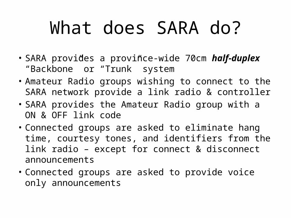
What does SARA do?
• SARA provides a province-wide 70cm half-duplex “Backbone” or “Trunk” system
• Amateur Radio groups wishing to connect to the SARA network provide a link radio & controller
• SARA provides the Amateur Radio group with a ON & OFF link code
• Connected groups are asked to eliminate hang time, courtesy tones, and identifiers from the link radio – except for connect & disconnect announcements
• Connected groups are asked to provide voice only announcements

Development of the Backbone
• Calgary (VE6OIL), Red Deer (VE6REP), and Edmonton (VE6NHB) sites are established with 2m “drop repeaters”
• 70cm “Hub Repeaters” are installed in Vulcan (VE6AAP), Red Deer (VE6REP), & Edmonton (VE6NHB)
• VE6OIL, VE6REP, and VE6NHB are connected together using “pass-through” sites at Pigeon Lake & Balzac (now Carstairs)
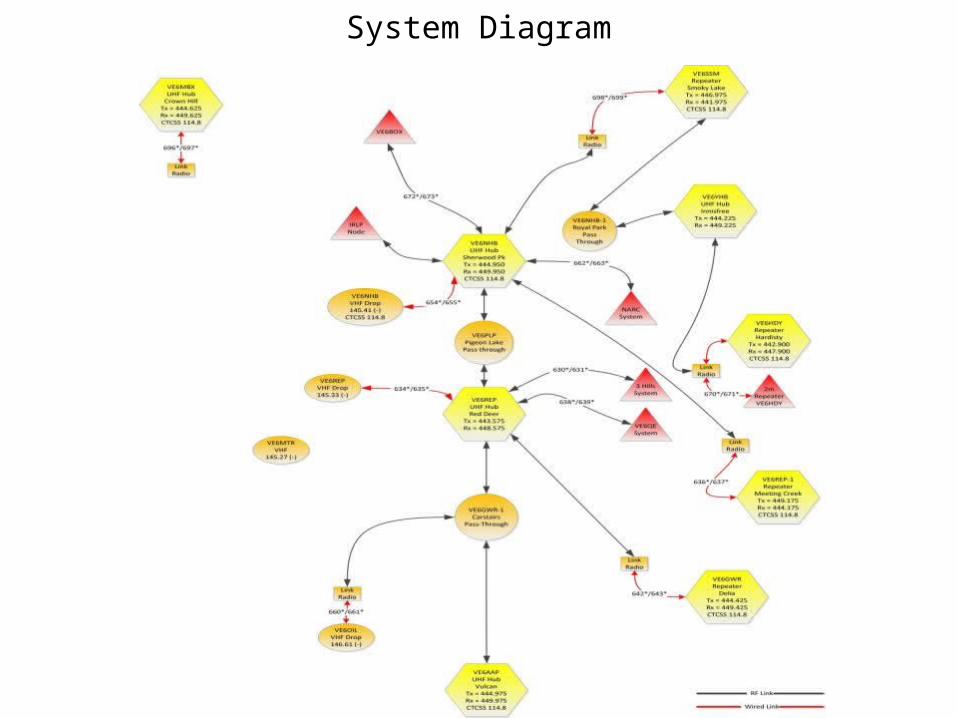
System Diagram

System Diagram

Hardware
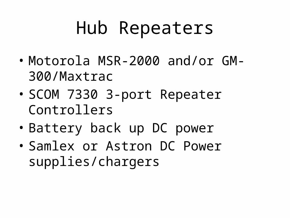
Hub Repeaters
• Motorola MSR-2000 and/or GM-300/Maxtrac• SCOM 7330 3-port Repeater Controllers• Battery back up DC power• Samlex or Astron DC Power supplies/chargers

Pass Through Sites
• 2 x Motorola GM-300 and/or Maxtrac• 2-port Repeater Controllers or DTMF
controller• Battery back up DC power• Samlex or Astron DC Power supplies/chargers

Repeater/Link Radios• Motorola GM-300 and/or Maxtrac• Maxtrac models require VCO alignment to perform
reliably in 70cm band• All link radios are modified to remove squelch
hysteresis• Depending on model, radio may have “hook switch”
modified to provide full CTCSS operation• All radios use 13.8 VDC power• All radios are run at 50% rated transmitter output
power with forced air cooling

Repeater/Link Radios

Repeater/Link Radios

Repeater/Pass Through Hardware

Repeater/Pass Through Hardware

Problems & Solutions

Problem: Kick-Back
HubRepeater
A
HubRepeater
B
PassThrough
The only cure for kick-back is to introduce delay at some point in the chain.
How do we stop this???

Kick-Back• Hub Repeater A transmits, the pass-through radios detect the
Hub Repeater carrier and begin transmitting to Hub Repeater B.
• Hub A drops transmit, and the pass-through radios stop transmitting VERY quickly.
• Hub B is still transmitting as it’s slower to “turn around” than the pass-through radios.
• Before Hub B drops carrier, the pass-through radios detect the carrier from Hub B and begin transmitting to Hub A.
• This starts a “Hub-to-Hub” oscillation or “kick-back”.• The only solution to this is to add delay at either Hub A, Hub
B, or the pass-through radios.• About 150ms (0.15 seconds) of delay is necessary to eliminate
kick-back between Hub repeaters.

Problem: Delay• Transmit-to-Receive & Receive-to-Transmit switching times
vary from radio to radio• CTCSS encode & decode times vary from radio to radio• Repeater/Link Controller internal switching times vary from
unit to unit• 20ms – 30ms delay is typical for one radio• After going through 9 radios (Calgary to Edmonton), total
delay is about 0.25 seconds• Adding in “kick-back” delay of about 0.3s, total one-way
delay time is just over 0.5 Seconds• Because of this, operators MUST hold their PTT down for
about 0.5 seconds before speaking!

Problem: Audio Levels
• Transmit-to-Receive & Receive-to-Transmit audio levels vary from radio to radio, and controller-to-controller
• Setting correct repeater & link radio audio levels is CRITICAL
• Incorrect audio levels are “multiplied” by poorly aligned repeaters & links resulting in poor audio quality throughout the network
• Audio levels are properly set using a (calibrated) signal generator, FM modulation analyzer, and oscilloscope

Problem: DTMF Twist
Highest frequency span = A 697Hz – 1633Hz 936Hz

Problem: DTMF Twist• DTMF tones must travel the length of the network and be
decoded at all points.• If the system audio response is not “flat”, DTMF tones will
be received at significantly different levels. If the high frequencies are emphasised, the high frequency DTMF tone may be as much as 8dB louder than the low tone.
• Modern DTMF decoders will work with up to +/- 6 dB of twist. If incoming audio tones are twisted by more than 6dB, DTMF decoding will NOT take place.
• Repeater controllers expect to see de-emphasised audio input, so all SARA link radios & repeaters use de-emphasised (filtered) audio, and all CTCSS tones are regenerated at every point in the system.

Future Plans

Conclusion• The SARA system is in the process of change - the
SARA Web site will have the latest news on the system at all times: http://www.saralink.ca
• SARA welcomes queries from Amateur Radio groups wishing to join the system.
• The ultimate goal is to have the SARA system cover the majority of populated centres in Alberta.
• SARA encourages ALL Amateur Radio operators to make use of the system for use while travelling, checking into province-wide nets, and/or disaster (emergency) communications.

Question Period
• Questions???• Handouts:– SARA System Diagram– SARA System Chart
Thank You! Ray Semenoff VE6RHS – [email protected]