The Self-adjusting File (SAF). Part 1: Respecting the Root Canal Anatomy—A New Concept of Endodontic Files and Its Implementation Zvi Metzger, DMD,* † Ehud Teperovich, DMD, † Raviv Zary, DMD, † Raphaela Cohen, DMD, † and Rafael Hof, MSc (Eng) † Abstract Aim: To introduce a new concept, the self-adjusting file (SAF), and discuss its unique features compared with current rotary nickel-titanium file systems. The New Concept: The SAF file is hollow and designed as a thin cylindrical nickel-titanium lattice that adapts to the cross-section of the root canal. A single file is used throughout the procedure. It is inserted into a path initially prepared by a # 20 K-file and operated with a transline- (in-and-out) vibration. The resulting circum- ferential pressure allows the file’s abrasive surface to gradually remove a thin uniform hard-tissue layer from the entire root canal surface, resulting in a canal with a similar cross-section but of larger dimensions. This holds also for canals with an oval or flat cross-section, which will be enlarged to a flat or oval cross-section of larger dimensions. The straightening of curved canals is also reduced because of the high pliability of the file and the absence of a rigid metal core. Thus, the original shape of the root canal is respected both longitudinally and in cross-section. The hollow SAF file is operated with a constant flow of irrigant that enters the full length of the canal and that is activated by the vibration and is replaced continuously throughout the procedure. This results in effective cleaning even at the cul de sac apical part of the canal. The SAF has high mechanical endur- ance; file separation does not occur; and mechanical failure, if it occurs, is limited to small tears in the lattice- work. Conclusion: The SAF represents a new step forward in endodontic file development that may over- come many of the shortcomings of current rotary nickel-titanium file systems. (J Endod 2010;36:679–690) Key Words Canal preparation, curved root canals, endodontic files, flat root canals, micro–computed tomography scan, nickel-titanium, SAF, scanning electron microscopy, self-adjusting file T he cleaning and shaping of the root canal is the key step in root canal treatment. Its aim is to remove all tissue debris from the root canal space while removing the inner layers of root canal dentin (1). For many years, it has been a common practice to enlarge the root canal to at least three ISO sizes larger than the first file to bind at the apical part of the canal (2, 3). It was assumed that such preparation will remove the inner layers of the dentin while allowing the irrigant to reach the entire length of the root canal for a thorough cleaning and disinfection of the root canal space (4, 5). This goal is easier to achieve today, even in curved root canals, because of the introduction and use of rotary nickel-titanium file systems. Because of their elasticity, these files can preserve the location of the root canal axis, thus largely preventing its transportation and ledging, which were major problems with stainless steel hand files. Rotary nickel-titanium files do this more efficiently and apparently require less operator expertise. The resulting root canal filling radio- graphs are impressive, yet the third dimension of the root canal is commonly ignored (6). The goal of cleaning and shaping may be easily and reproducibly achieved with rotary files as far as relatively straight and narrow root canals with a round cross-section are concerned. In such canals, completion of the file sequence may result in a clean canal with no tissue debris and with removal of all or most of the inner layer of the heavily contaminated dentin. Nevertheless, in flat oval-shaped root canals and in curved ones, this goal is not easy attainable (7, 8). Flat oval root canals are common in the distal roots of lower molars, upper and lower bicuspids, and lower incisors and canines. Asymmetrical, flat, tear-shaped cross-sections are another challenge. Such canals are common in most roots that contain two root canals in the same root and a potential isthmus. This includes ante- rior roots of lower molars, mesiobuccal roots of upper molars, first upper bicus- pids, and some lower incisors. A systematic and comprehensive study by Wu et al (9) has shown that oval or flat root canal morphology is present in up to 25% of root canals, and in certain root groups it may exceed 50%. The flatness or asym- metry in these canals is usually in the buccolingual dimension; therefore, it fails to be recognized on clinical radiographs, which represent a buccolingual projection (Fig. 1). The buccal and lingual areas of such flat root canals and the area facing the isthmus in tear-shaped ones cannot be adequately prepared by current rotary files. All current rotary files have one or another type of spiral blade and helical formation that when rotating machines the root canal into a form that has a round cross-section. Substantial untouched areas may be left on the buccal and lingual sides of a flat root From the *Department of Endodontology, The Goldschleger School of Dental Medicine, Tel Aviv University, Tel Aviv, Israel; and † ReDent-Nova Inc, Ra’anana, Israel. Dr Ehud Teperovich, Dr Raviv Zary, Dr Raphaela Cohen, and Eng Rafael Hof are employed by ReDent-Nova, manufacturer of the SAF file. Dr Zvi Metzger serves as a scientific consultant to the same company. Address requests for reprints to Dr Zvi Metzger, School of Dental Medicine, Tel Aviv University, Ramat Aviv, Tel Aviv, Israel. E-mail address: [email protected]. 0099-2399/$0 - see front matter Copyright ª 2010 American Association of Endodontists. doi:10.1016/j.joen.2009.12.036 Basic Research—Technology JOE — Volume 36, Number 4, April 2010 The Self-adjusting File. Part 1 679
Transcript
The Self-adjusting File (SAF). Part 1: Respecting the RootCanal Anatomy—A New Concept of Endodontic Files and ItsImplementationZvi Metzger, DMD,*† Ehud Teperovich, DMD,† Raviv Zary, DMD,† Raphaela Cohen, DMD,†
and Rafael Hof, MSc (Eng)†
AbstractAim: To introduce a new concept, the self-adjusting file(SAF), and discuss its unique features compared withcurrent rotary nickel-titanium file systems. The NewConcept: The SAF file is hollow and designed asa thin cylindrical nickel-titanium lattice that adapts tothe cross-section of the root canal. A single file is usedthroughout the procedure. It is inserted into a pathinitially prepared by a # 20 K-file and operated witha transline- (in-and-out) vibration. The resulting circum-ferential pressure allows the file’s abrasive surface togradually remove a thin uniform hard-tissue layer fromthe entire root canal surface, resulting in a canal witha similar cross-section but of larger dimensions. Thisholds also for canals with an oval or flat cross-section,which will be enlarged to a flat or oval cross-sectionof larger dimensions. The straightening of curved canalsis also reduced because of the high pliability of the fileand the absence of a rigid metal core. Thus, the originalshape of the root canal is respected both longitudinallyand in cross-section. The hollow SAF file is operatedwith a constant flow of irrigant that enters the full lengthof the canal and that is activated by the vibration and isreplaced continuously throughout the procedure. Thisresults in effective cleaning even at the cul de sac apicalpart of the canal. The SAF has high mechanical endur-ance; file separation does not occur; and mechanicalfailure, if it occurs, is limited to small tears in the lattice-work. Conclusion: The SAF represents a new stepforward in endodontic file development that may over-come many of the shortcomings of current rotarynickel-titanium file systems. (J Endod 2010;36:679–690)
The cleaning and shaping of the root canal is the key step in root canal treatment.Its aim is to remove all tissue debris from the root canal space while removing
the inner layers of root canal dentin (1). For many years, it has been a commonpractice to enlarge the root canal to at least three ISO sizes larger than the first fileto bind at the apical part of the canal (2, 3). It was assumed that such preparationwill remove the inner layers of the dentin while allowing the irrigant to reach theentire length of the root canal for a thorough cleaning and disinfection of the rootcanal space (4, 5). This goal is easier to achieve today, even in curved root canals,because of the introduction and use of rotary nickel-titanium file systems. Becauseof their elasticity, these files can preserve the location of the root canal axis, thuslargely preventing its transportation and ledging, which were major problems withstainless steel hand files. Rotary nickel-titanium files do this more efficiently andapparently require less operator expertise. The resulting root canal filling radio-graphs are impressive, yet the third dimension of the root canal is commonlyignored (6).
The goal of cleaning and shaping may be easily and reproducibly achieved withrotary files as far as relatively straight and narrow root canals with a round cross-sectionare concerned. In such canals, completion of the file sequence may result in a cleancanal with no tissue debris and with removal of all or most of the inner layer of theheavily contaminated dentin. Nevertheless, in flat oval-shaped root canals and in curvedones, this goal is not easy attainable (7, 8).
Flat oval root canals are common in the distal roots of lower molars, upper andlower bicuspids, and lower incisors and canines. Asymmetrical, flat, tear-shapedcross-sections are another challenge. Such canals are common in most roots thatcontain two root canals in the same root and a potential isthmus. This includes ante-rior roots of lower molars, mesiobuccal roots of upper molars, first upper bicus-pids, and some lower incisors. A systematic and comprehensive study by Wu et al(9) has shown that oval or flat root canal morphology is present in up to 25%of root canals, and in certain root groups it may exceed 50%. The flatness or asym-metry in these canals is usually in the buccolingual dimension; therefore, it fails tobe recognized on clinical radiographs, which represent a buccolingual projection(Fig. 1).
The buccal and lingual areas of such flat root canals and the area facing theisthmus in tear-shaped ones cannot be adequately prepared by current rotary files.All current rotary files have one or another type of spiral blade and helical formationthat when rotating machines the root canal into a form that has a round cross-section.Substantial untouched areas may be left on the buccal and lingual sides of a flat root
From the *Department of Endodontology, The Goldschleger School of Dental Medicine, Tel Aviv University, Tel Aviv, Israel; and †ReDent-Nova Inc, Ra’anana, Israel.Dr Ehud Teperovich, Dr Raviv Zary, Dr Raphaela Cohen, and Eng Rafael Hof are employed by ReDent-Nova, manufacturer of the SAF file. Dr Zvi Metzger serves as
a scientific consultant to the same company.Address requests for reprints to Dr Zvi Metzger, School of Dental Medicine, Tel Aviv University, Ramat Aviv, Tel Aviv, Israel. E-mail address: [email protected].
0099-2399/$0 - see front matterCopyright ª 2010 American Association of Endodontists.
doi:10.1016/j.joen.2009.12.036
Basic Research—Technology
JOE — Volume 36, Number 4, April 2010 The Self-adjusting File. Part 1 679
canal or on the side facing the isthmus in tear-shaped ones (Fig. 2). Asimilar problem has been shown by Wu et al (7, 8) with hand files.
Current technology may mislead the operator to believe that thecanal has been adequately shaped when, in fact, recesses full of infected
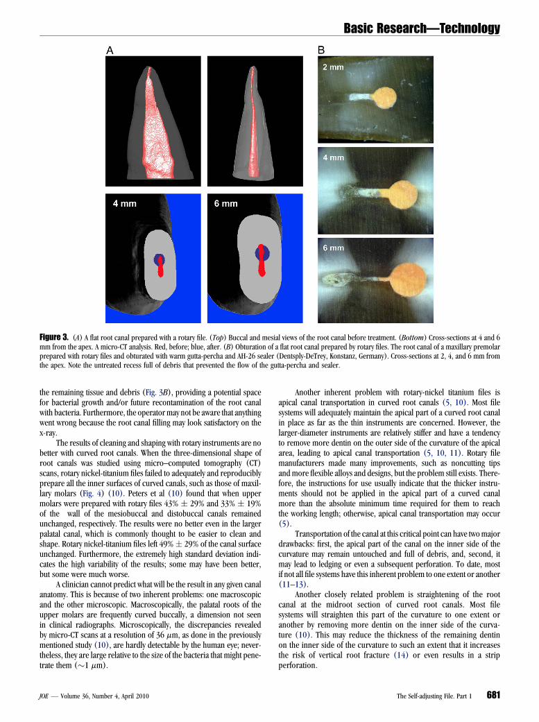
tissue and debris may have been left on the buccal and/or lingual sidesof the area prepared by the rotary file (Fig. 3A). Furthermore, such rootcanals may never be adequately obturated and sealed because the rootcanal filling or even the sealer will be separated from the canal wall by
Figure 1. The limited value of two-dimensional radiographs. All three root canal cross-sections look the same on buccolingual projection radiographs.
Figure 2. Schematic cross-sections of flat and tear-shaped root canals. Preparation with rotary files alone cannot adequately clean the (A) flat or (upper part of C)tear-shaped canals. Attempts to use larger instruments to include the whole cross-section may lead to localized thinning of the remaining dentinal wall. (B and lowerpart of C) The SAF enlarges the canal to the same shape with bigger dimensions.
Basic Research—Technology
680 Metzger et al. JOE — Volume 36, Number 4, April 2010
the remaining tissue and debris (Fig. 3B), providing a potential spacefor bacterial growth and/or future recontamination of the root canalwith bacteria. Furthermore, the operatormay not be aware that anythingwent wrong because the root canal filling may look satisfactory on thex-ray.
The results of cleaning and shaping with rotary instruments are nobetter with curved root canals. When the three-dimensional shape ofroot canals was studied using micro–computed tomography (CT)scans, rotary nickel-titanium files failed to adequately and reproduciblyprepare all the inner surfaces of curved canals, such as those of maxil-lary molars (Fig. 4) (10). Peters et al (10) found that when uppermolars were prepared with rotary files 43% ! 29% and 33% ! 19%of the wall of the mesiobuccal and distobuccal canals remainedunchanged, respectively. The results were no better even in the largerpalatal canal, which is commonly thought to be easier to clean andshape. Rotary nickel-titanium files left 49%! 29% of the canal surfaceunchanged. Furthermore, the extremely high standard deviation indi-cates the high variability of the results; some may have been better,but some were much worse.
A clinician cannot predict what will be the result in any given canalanatomy. This is because of two inherent problems: one macroscopicand the other microscopic. Macroscopically, the palatal roots of theupper molars are frequently curved buccally, a dimension not seenin clinical radiographs. Microscopically, the discrepancies revealedby micro-CT scans at a resolution of 36 mm, as done in the previouslymentioned study (10), are hardly detectable by the human eye; never-theless, they are large relative to the size of the bacteria that might pene-trate them ("1 mm).
Another inherent problem with rotary-nickel titanium files isapical canal transportation in curved root canals (5, 10). Most filesystems will adequately maintain the apical part of a curved root canalin place as far as the thin instruments are concerned. However, thelarger-diameter instruments are relatively stiffer and have a tendencyto remove more dentin on the outer side of the curvature of the apicalarea, leading to apical canal transportation (5, 10, 11). Rotary filemanufacturers made many improvements, such as noncutting tipsand more flexible alloys and designs, but the problem still exists. There-fore, the instructions for use usually indicate that the thicker instru-ments should not be applied in the apical part of a curved canalmore than the absolute minimum time required for them to reachthe working length; otherwise, apical canal transportation may occur(5).
Transportation of the canal at this critical point can have twomajordrawbacks: first, the apical part of the canal on the inner side of thecurvature may remain untouched and full of debris, and, second, itmay lead to ledging or even a subsequent perforation. To date, mostif not all file systems have this inherent problem to one extent or another(11–13).
Another closely related problem is straightening of the rootcanal at the midroot section of curved root canals. Most filesystems will straighten this part of the curvature to one extent oranother by removing more dentin on the inner side of the curva-ture (10). This may reduce the thickness of the remaining dentinon the inner side of the curvature to such an extent that it increasesthe risk of vertical root fracture (14) or even results in a stripperforation.
Figure 3. (A) A flat root canal prepared with a rotary file. (Top) Buccal and mesial views of the root canal before treatment. (Bottom) Cross-sections at 4 and 6mm from the apex. A micro-CT analysis. Red, before; blue, after. (B) Obturation of a flat root canal prepared by rotary files. The root canal of a maxillary premolarprepared with rotary files and obturated with warm gutta-percha and AH-26 sealer (Dentsply-DeTrey, Konstanz, Germany). Cross-sections at 2, 4, and 6 mm fromthe apex. Note the untreated recess full of debris that prevented the flow of the gutta-percha and sealer.
Basic Research—Technology
JOE — Volume 36, Number 4, April 2010 The Self-adjusting File. Part 1 681
Accurate length measurement is an essential prerequisite for theuse of any rotary file. The thin nickel-titanium rotary files are extremelyflexible and may negotiate even a canal with a rather sharp apical curve.When a rotary file accidentally passes the apical foramen of sucha curved canal, because of either misleading length measurement orfailure to keep the marker on the file in place, it may soon lacerateor zip the apical foramen and form an oval opening with potentialloss of the apical constriction. This may turn a simple root canalanatomy into a more complex one that is more difficult to handle. Slip-ping of the master cone beyond the apex during lateral condensation orextrusion of heat-softened gutta-percha may be one of the results.
Unexpected separation of rotary nickel titanium files was and stillis the major drawback. Improvements in metallurgy, design, surfacetreatment, quality control, and, above all, the introduction of hands-on training, have significantly reduced the extent of this problem, never-theless it is still with us. As opposed to stainless steel files that may givea ‘‘warning’’ by some distortion that appears in an abused file, usually nosuch macroscopic sign will appear in a rotary nickel titanium file.Furthermore, even in the era of microscope-assisted root canal treat-ment, a separated nickel-titanium file screwed in at the apical part ofan even slightly curved canal is much more difficult to remove thana similar segment of a stainless steel file.
Rotary nickel-titanium files have been a great step forward inmodern root canal treatment. They allow efficient shaping in curvedcanals that were hardly negotiable before while reasonably maintainingtheir original long axis in its original position. Nevertheless, to over-come the inherent remaining problems of the nickel-titanium instru-ments, a new concept in cleaning and shaping is warranted; hence,the self-adjusting file (SAF) was developed.
The SAFDesign and Mode of Operation
The SAF is a hollow file designed as a compressible, thin-walledpointed cylinder either 1.5 or 2.0 mm in diameter composed of 120-mm-thick nickel-titanium lattice (Fig. 5A). The 1.5-mm file may easilybe compressed to the extent of being inserted into any canal previouslyprepared or negotiated with a # 20 K-file (Fig. 5B) (15). The 2.0-mmfile will easily compress into a canal that was prepared with a #30 K-file.The file will then attempt to regain its original dimensions, thus applyinga constant delicate pressure on the canal walls (15). When inserted intoa root canal, it adapts itself to the canal’s shape, both longitudinally (aswill any nickel titanium file) and along the cross-section. In a roundcanal, it will attain a round cross-section, whereas in an oval or flat canalit will attain a flat or oval cross-section, providing a three-dimensionaladaptation (Fig. 5C). The surface of the lattice threads is lightly abrasive(Fig. 5D), which allows it to remove dentin with a back-and-forthgrinding motion (15).
The SAF is operated with transline (in and out) vibrating handpie-ces with 3,000 to 5,000 vibrations per minute and an amplitude of 0.4mm. Such a handpiece may be the KaVo GENTLEpower or equivalentcombined with either a 3LDSY head (360# free rotation; Kavo, BiberachRiss Germany) (Fig. 6) or MK-Dent head (360# free rotation; MK-Dent,Bargteheide, Germany) or RDT3 head (80 rpm when free and stopsrotating when engaging the canal walls, recently developed by Re-Dent-Nova, Ra’anana, Israel). The vibrating movement combined withintimate contact along the entire circumference and length of the canalremoves a layer of dentin with a grinding motion (see later).
The hollow design allows for continuous irrigation throughout theprocedure. A special irrigation device (VATEA, ReDent-Nova) is con-nected by a silicon tube to the irrigation hub on the file (Fig. 5A and6) and provides continuous flow of the irrigant of choice at a low
Figure 4. Micro-CT analysis of preparation of curved root canals using rotarynickel-titanium files. (A) Before, (B) after, and (C) three-dimensional anal-ysis. Clear, prepared canal; green, affected surface; red, surface unchangedby the file. Reproduced with permission from Peters OA, Peters CI, Schonen-berger K, et al. ProTaper rotary root canal preparation: effects of root canalanatomy on final shape analyzed by micro CT. Int Endod J 2003;36:86-92.
Basic Research—Technology
682 Metzger et al. JOE — Volume 36, Number 4, April 2010
pressure and at flow rates of 1 to 10 mL/min. Alternatively, any physi-odispenser type of irrigation device (ie, NSK Surgic XT Micro MotorSystem, Kanuma, Japan, or W&H ImplantMed, Burmoos, Austria) thatis primarily designed for implantology may also be used.
The SAF is inserted into the canal while vibrating and is delicatelypushed in until it reaches the predetermined working length. It is thenoperated with in-and-out manual motion and with continuous irrigationusing two cycles of 2minutes each for a total of 4minutes per canal. Thisprocedure will remove a uniform dentin layer 60- to 75-mm thick fromthe canal circumference (15) (Fig. 7A and B). The SAF file is designedfor single use.
An Self-adjusting File that Adapts Itself to the Three-Dimensional Anatomy of Root Canals
The SAF file is different from any current nickel-titanium rotaryfile. Most rotary file systems will find the widest part of the canal andgradually machine it, using several files of increasing diameter, toa wider canal with a round cross section. If the canal happens to be rela-tively narrow, the whole original canal may be included in the prepara-tion. However, if the canal is flat, oval, tear shaped, or simply large, thismode of preparation may leave untreated recesses, mainly buccally orlingually to the machined part of the canal (Figs. 2 and 3A and B).
The SAF is used as a single file (of either 1.5- or 2.0-mm diameter)that starts as a narrow, compressed, shape and gradually expands in thecanal while removing a uniform layer of dentin from its walls. Becausethe file adapts itself to the cross-section of a given canal, a canal witha round cross-section is enlarged as a round canal, whereas an ovalcanal is enlarged as an oval canal of larger dimensions (Figs. 2 and7A). Even an extreme root canal anatomy, such as presented inFigure 7B, lends itself to this mode of operation. High-resolutionthree-dimensional micro-CT analysis showed that high percentage(83.2%) of the canal wall is affected by the SAF file even in oval, flatroot canals (Table 1).
Uniform Removal of Dentin and Remaining WallThickness
When operated in flat root canals, rotary nickel-titanium files mayresult in uneven thickness of the remaining dentin wall. In places inwhich the round bore has been created, the remaining dentin will bethinner in the mesial and distal aspects than in the untreated areas(Fig. 2). When excessive apical preparations are used in an attemptto include as much of the irregular canal space in the preparation aspossible (16, 17), the uneven thicknessmay be evenmore pronounced.This uneven thickness of the remaining dentin wall may be
Figure 5. (A) The SAF. (A) Shank for attachment to a transline vibrating handpiece (in-and-out motion). (B) Connector (hub) for the irrigation tube. (B) The SAFcompressed into a canal prepared by a # 20 K file. Right: A # 20 K file. (Left) The SAF compressed into the same canal. (C) Three dimensional adaptation of the SAFfile. The SAF inserted into the root canal of a lower bicuspid with a flat canal. Left: bucco-lingual projection. (Right) Mesiodistal projection. (D) Abrasive surface ofthe SAF file (25$ magnification).
Basic Research—Technology
JOE — Volume 36, Number 4, April 2010 The Self-adjusting File. Part 1 683
a predisposing factor for vertical root fractures (14). On the other hand,the SAF removes a uniform layer of dentin from the canal walls, thusresulting in a relatively uniform remaining dentin wall thickness andavoiding the previously mentioned risk (Figs. 2 and 7A and B).
Prevention of Canal TransportationThe SAF file is extremely flexible and pliable. It does not impose its
shape on the canal but rather complies with its original shape. This istrue both circumferentially and longitudinally. The long axis of theapical part of curved canals is kept closer to its original place than re-ported for rotary files: a mean center-of-mass shift of 68.8 ! 7.7 mmcompared with the shift of 120 to 135mm previously reported by Peterset al with rotary files in similar canals (10) (Table 2 and Fig. 8A). Incurved canals, the thicker rotary nickel-titanium files have a tendencyto transport the canal to the outer side of the curvature (Fig. 4)(10). When the SAF is used to enlarge the canal to similar dimensions,it tends to keep the apical part of curved canals closer to its originallocation (Fig. 8A).
When rotary files accidentally pass the apical foramen of anapically curved canal, because of misleading length measurement orfailure to maintain the marker in place, they may soon ‘‘zip’’ the apicalforamen and form an oval opening. The SAF, on the other hand, may beoperated in such conditions even for few minutes with no zipping what-soever (Fig. 8B).
High DurabilityThe SAF file is extremely durable and may go through rather severe
abuse before a mechanical failure will occur. It does not have a core as
do other nickel-titanium instruments. Any strain applied to it is distrib-uted along many of its delicate parts, and the total endurance is a func-tion of the accumulated endurance of each of these individual parts.
Some of the tests used to compare the endurance of endodonticfiles are not directly relevant to this file’s mode of operation; neverthe-less, they are indicative of its high durability (15). When torque dura-bility was tested, the SAF can be turned 7$ 360# before separation witha torque durability of 29.7 g/cm (15). These values are well beyond theISO3630-1 requirement (1$ 360# rotation and 18 g/cm in the torquedurability test) and above that of many of the instruments compared ina recent American Dental Association Professional Product Review(18).
When the American Dental Association cyclic fatigue test isapplied, SAF can be rotated for more than 150 hours at 900 rpmwith a 5-mm deflection with no mechanical failure (15), whereassome of the nickel-titanium rotary instruments separated within the firsthour or even within a few minutes (18). As mentioned previously, thesetests are indicative of the SAF’s durability, even though the SAF’s mode ofoperation is a transline vibrating motion. A buckling test is more rele-vant to study the endurance of the SAF. The SAF can endure more than600,500 consecutive 6-mm type I free buckling cycles before anymechanical damage could be observed (15). This represents an equiv-alent of"120 minutes of a rather abusive operation at 5,000 vibrationsper minute.
A specially designed test apparatus (Fig. 9A) allows the SAF to becontinuously operated in simulated canals using the up and downmotion of the handpiece, as used clinically. During this testing, theinstruments were taken out and inspected every 1 minute. The SAFfile was operated in this test for 29.1! 1.2 minute before any structuralfailure appeared (15) (Fig. 9A).
After all this, the ultimate endurance test is the real-life test: oper-ation in root canals. The SAF can be operated for 27 minutes in ex-tracted human teeth before any structural failure appears. Thisrepresents more than 6 times the 4-minute operation time per canal,which is sufficient to achieve the desired results (15).
It is of particular importance to note that even when structuralfailure did occur, it was not of the separation type that is encounteredwith other nickel-titanium files. Detachment of one of the arches at oneof its ends was the typical mechanical failure (15) (Fig. 9B). Thedamaged file could easily be retrieved from the canal, facing none ofthe challenges that a separated rotary nickel-titanium file presents.
Continuous Irrigation with Sodium HypochloriteIrrigation of the root canal with copious amounts of sodium hypo-
chlorite during root canal treatment is widely recommended (19, 20).It has been well documented that when exposed to its target of bacteriaand tissue debris, sodium hypochlorite loses its activity rather quickly(21). Taking into account the extremely small volume of the root canal,the amount of sodium hypochlorite contained in the canal loses itsactivity within a very short time. Therefore, as frequent replacementof the irrigant as possible is mandatory for maintaining its optimalpotency and effect.
The SAF operates with a continuous flow of the irrigant, thus allow-ing continuous fresh irrigant to be present in the canal at all times. Thevibration of the file’s metal lattice within the irrigant facilitates its clean-ing and debridement effects (22, 23).
Effective sodium hypochlorite replacement in the apical part of thecanal is essential to provide its full effect and benefits in this critical areaduring root canal treatment. The extent of irrigant replacement in theapical part of curved narrow canals was previously studied using clearresin blocks with simulated curved canals filled with colored liquid
Figure 6. A KaVo transline vibrating handpiece. The irrigation tube is con-nected to a continuous-flow source and has an on-off switch (white).
Basic Research—Technology
684 Metzger et al. JOE — Volume 36, Number 4, April 2010
(24). Using the same model, it was evident that syringe and needle irri-gation was ineffective in replacing the liquid in the apical part ofa narrow curved canal. On the other hand, the SAF, which was usedwith continuous irrigation, combined with the vibrating action of themetal lattice, was effective at replacing the liquids in the apical part ofthe canal (Fig. 10A).
The effective replacement of irrigant in the apical part of the canaloccurs with no clinically significant positive pressure. No pressurebuilds up in the canal during the SAF operation because the metalmesh allows free escape of the irrigant at all times. Even in the narrowapical part of a canal 200mm in diameter (a canal prepared up to a #20K-file), the SAF represents a very ineffective piston, with 38% of the canalcross-section area free for the irrigants backflow (Fig. 10B) (15).
No irrigant passes the apical foramen during SAF operation (15).This may be understood if pressure analysis in this critical area isstudied. Three pressure types may potentially be present in the apicalpart of the canal during SAF operation: hydrostatic pressure represent-ing the water column in the canal, stagnating pressure generated by thevibration of an object in the fluid, and piston pressure resulting from theapical thrust of the SAF. All these may be calculated and sum up to a totalpressure of 394 Pa (15).
The simple surface tension of the external fluid at an even largerapical foramen 350 mm in diameter requires a calculated eruptionpressure of 832 Pa to allow fluid from the canal to escape beyond
the apical foramen (15). The pressure required will be much higherif tissue is present periapically. Therefore, the passage of irrigant tothe periapical area as a result of the SAF’s action is highly unlikely.This is in agreement with the lack of any postoperative pain when theSAF is used clinically.
These values should be compared with (i) the potential calculatedpiston pressure that a well-adapted K-file might generate when intro-duced into the apical part of a narrow canal full of irrigant("199,700 Pa when a #25 file is pushed with a force of 1 g) (15)and (ii) with the pressure generated when a syringe is used for irriga-tion at 5mL/min with a 25-G needle that is loosely adapted into the canalspace. Even if 38% of the cross-section area of the canal is left freearound the needle, for the escape of the irrigant’s backflow, a calculatedpressure of 1,270 Pa will occur (15).
Removal of the Smear Layer in the Apical Part of theCanal
As with any other mechanical device, the SAF forms a smear layeron the canal walls (23). This layer should be removed in order to allowintimate, unobstructed contact of antibacterial agents with bacteria atthe orifices of dentinal tubules and also to optimize the sealer’s adap-tation to the canal walls and thus prevent the future formation ofa gap between them (25–27). A final wash with a chelating agent
Figure 7. (A) SAF preparation: an upper second bicuspid with a flat root canal. (Top) Buccal and mesial views. (Bottom) Cross-sections at 4 and 6 mm from theapex. A micro-CT analysis. Red, before; blue, after. (B) SAF preparation: distal root of a first lower molar. (Top) Two views presenting a curved flat canal witha mesial, spoon-shaped concavity. (Bottom) Cross-section at 6 mm from the apex. A micro-CT analysis. Red, before; blue, after.
Basic Research—Technology
JOE — Volume 36, Number 4, April 2010 The Self-adjusting File. Part 1 685
such as EDTA or citric acid has recently become widely used to removethe smear layer before obturation. Nevertheless, scanning electronmicroscopic studies indicate that the removal of the smear layer andultramicroscopic debris in the apical third of the canal using eithera syringe and a needle or a chelator paste leaves much to be desired(28–31).
When 3% sodium hypochlorite and 17% EDTA were used as alter-nating irrigants with the SAF file, the root canal surface (including its
apical third) was rendered clean of debris and the smear layer (23)(Fig. 11). This may be attributed to both the effective continuousreplacement of the chelator in the apical region and to the mechanical
TABLE 1. Micro-CT Analysis of SAF Preparation in Oval and Flat Root Canals
SAF, self-adjusting file; SEM, standard error of the mean.
*Ratio between buccolingual and mesiodistal dimensions of the root canal, at 4 mm from the apex,
used as a measure of the canal’s flatness.†Percent of root canal walls pixels before the procedure unaffected by the file, calculated from before
and after micro-CT scans, as done by Peters et al (10).
TABLE 2. Canal Transportation by the SAF File in the Apical Third of CurvedRoot Canals: Center-of-Mass Shift Analysis*
Root typeCenter of mass
shift in the apical third
MB rootof maxillary molar
104.7*
DB rootof maxillary molar
92.6
Palatal rootof maxillary molar
41.3
Palatal tootof maxillary molar
58.5
DB rootof maxillary molar
35.8
Palatal rootof maxillary molar
86.3
MB rootof maxillary molar
58.3
Palatal rootof maxillary molar
74.9
MB rootof maxillary molar
35.38
Palatal rootof maxillary molar
68.8
Mean (! SEM) 68.8 (! 7.65)
DB, distobuccal; MB, mesiobuccal; SAF, self-adjusting file; SEM, standard error of the mean.
*Mean center of mass shift (mm) calculated from before and after micro-CT scans (10).
Figure 8. (A) SAF preparation in a curved canal. A micro-CT scan and analysis. (Top) Before treatment (red) and (bottom) after treatment (blue). (B) Pres-ervation of the apical foramen. (A) A sharp apical curve with the foramen facing laterally. (B) A SAF file was passed through the apical foramen and operated for 4minutes. (C) The apical foramen was kept round and was not zipped by the procedure.
Basic Research—Technology
686 Metzger et al. JOE — Volume 36, Number 4, April 2010
vibrating action of the SAF in this region. This combination results ina cleaner apical canal surface than most other reported methods canachieve (23, 28–31).
Root Canal ObturationRoot canal obturation of SAF-prepared root canals may be done by
any of the common methods. Adaptation to the canal walls is possibleeven in flat canals because of the thorough cleaning of the otherwisedifficult to clean recesses (Fig. 12A).
Obturation using lateral compaction using chloroform-dippedcustomized master cones (3, 32) is of particular interest because itallows the operator to actually visualize the shape of the SAF-treatedroot canal as reproduced on the customized master cone. Such mastercones are presented in Figure 12B. It is evident that the apical part of thepreparation is far from being round in the cross-section but ratherrepresents the enlarged 3D shape of the canal. It is also clear that ifa standardized master cone is used to gauge the prepared canal size,it may provide rather limited and misleading information (Fig. 12B).
Clinical UseThe SAF file has been approved for clinical use in Israel (Israeli
Ministry of Health, License no. 11940000) as well as in Europe (CEmark no. 0483). A series of clinical vital and nonvital cases have already
Figure 9. (A) A testing setup for SAF file durability. The file is operated usinga vibrating handpiece which is moved slowly up and down, mimicking the clin-ical operation. (B) Mechanical failure of the SAF. One connector detached atone of its ends. The instrument was easily retrieved from the canal.
Figure 10. (A) Replacement of irrigant in the apical third of a curved canal.Curved canals in clear training blocks were filled with colored liquid. (A) Nee-dle irrigation failed to wash out the colored liquid. (B) The SAF operated withcontinuous irrigation and vibration washed the colored liquid out. (B) A sche-matic presentation of the apical part of the SAF in a narrow root canal that wasprepared to #20 K-file. The apical part of the SAF collapses to a dual layer ofmetal, each element of which is 0.12-mm thick and 0.8-mm wide, thus forminga potential piston with a 0.12 $ 0.16 mm rectangular cross-section. Whenmoving into the canal, 40% of the cross-section of the canal is free and allowsbackflow of the irrigant, thus being a poor piston that cannot significantly raisethe pressure.
Basic Research—Technology
JOE — Volume 36, Number 4, April 2010 The Self-adjusting File. Part 1 687
been completed (Fig. 13). The radiographic images of root canal fillingsin SAF-prepared canals are no different than those of root canal fillingsin root canals prepared by other file systems (Fig. 13). No file separa-tion event was recorded in more than 100 clinical cases.
ConclusionsThe SAF represents a new approach in endodontic file design and
operation. Its main features are as follows:
1. A three-dimensional adaptation to the shape of the root canal,including adaptation to its cross-section.
2. One file is used throughout the procedure, during which it changesfrom an initially compressed form to larger dimensions.
Figure 11. Removal of the smear layer. The SAF was operated for two cycles of2 minutes with a continuous flow of 5% sodium hypochlorite during the firstminute of each cycle and 17% EDTA during the second minute. This was fol-lowed by a 0.5-minute EDTA flush through a passive SAF and a final short flushwith sodium hypochlorite to remove the EDTA. Representative fields from theapical, midroot, and coronal thirds of the root canal. Scanning electron micro-scopic magnification: $1,000.
Figure 12. (A) Root canal filling adaptation in a SAF-prepared flat root canal.The entire circumference of the canal was prepared, thus allowing root canalfilling penetration into the buccal and lingual areas of the canal. Cross-sectionsat 2, 4, and 6 mm from the apex. (B) Chloroform-dipped customized mastercones. They present a three-dimensional reproduction of the SAF-preparedcanal (A, B, rotated by 90#). (C) The standardized master cone fit witha tug-back sensation in the same prepared canal. (D) A master cone that fitinto the canal before SAF preparation.
Basic Research—Technology
688 Metzger et al. JOE — Volume 36, Number 4, April 2010
3. Canal straightening and canal transportation of curved canals arelargely avoided because of the lack of a rigid metal core. The filedoes not have ‘‘a will of its own.’’
4. High mechanical durability, thus overcoming the issue of separatednickel-titanium instruments.
5. Hollow design that allows continuous irrigation with constantrefreshment of the irrigant throughout the procedure.
References1. Peters LB, Wesselink PR, Buys JF, et al. Viable bacteria in root dentinal tubules of
teeth with apical periodontitis. J Endod 2001;27:76–81.2. Walton RE, Torabinejad M. Principles and Practice of Endodontics. 2nd ed. Phila-
delphia, PA: Saunders; 1996.3. Wein FS. Endodontic Therapy. 5th ed. St Louis, MO: Mosby; 1996.4. Shuping G, Ørstavic D, Sigurdsson A, et al. Reduction of intracanal bacteria using
nickel-titanium rotary instruments and various medications. J Endod 2000;26:751–5.
5. Peters OA. Current challenges and concepts in the preparation of root canal systems:a review. J Endod 2004;30:559–67.
6. Spangberg LS. The wonderful world of rotary root canal preparation. Oral Surg OralMed Oral Pathol Oral Radiol Endod 2001;92:479.
7. Wu M-K, Wesselink PR. A primary observation on the preparation and obturation inoval canals. Int Endod J 2001;34:137–41.
8. Wu M-K, van der Sluis LWM, Wesselink PR. The capacity of two hand instrumenta-tion techniques to remove the inner layer of dentin in oval canals. Int Endod J 2003;36:218–24.
9. Wu M-K, Roris A, Barkis D, et al. Prevalence and extent of long oval canals in theapical third. Oral Surg Oral Med Oral Pathol Oral Radiol Endod 2000;89:739–43.
10. Peters OA, Peters CI, Schonenberger K, et al. ProTaper rotary root canal prepara-tion: effects of root canal anatomy on final shape analyzed by micro CT. Int EndodJ 2003;36:86–92.
11. Javaheri HH, Javaheri GH. A comparison of three Ni-Ti rotary instruments in apicaltransportation. J Endod 2007;33:284–6.
12. Loizides AL, Kakavetsos VD, Tzanetakis GN, et al. A comparative study of the effect oftwo nickel-titanium preparation techniques on root canal geometry assessed by mi-crocomputed tomography. J Endod 2007;33:1455–9.
13. Varsiani MA, Pascon EA, de Sousa CJA, et al. Influence of shaft design on the shapingability of 3 nickel-titanium rotary systems by means of computerized tomography.Oral Surg, Oral Med Oral Pathol Oral Radiol Endod 2008;105:807–13.
14. Lertchirakam V, Palamara JE, Messer HH. Patterns of vertical root fracture: factorsaffecting stress distribution in the root canal. J Endod 2003;29:523–8.
15. Hof R, Perevalov V, Eltanani M, et-al. The Self Adjusting File (SAF), Part 2: mechan-ical analysis. J Endod (in press)
16. Kerekes K, Tronstad L. Morphologic observations on root canals of human molars. JEndod 1977;3:114–8.
17. Card SJ, Sigurdsson A, Ørstavic D, et al. The effectiveness of increased apicalenlargement in reducing intracanal bacteria. J Endod 2002;28:779–83.
19. Estrela C, Estrela CRA, Barbin EL, et al. Mechanism of action of sodium hypochlorite.Braz Dent J 2002;13:113–7.
20. Buchanan LS. The standardized-taper root canal preparation: part 3. GT file tech-nique in large root canals with small apical diameter. Int Endod J 2001;34:149–56.
21. Haapasalo M, Qian W. Irrigants and intracanal medicaments. In: Ingle JI,Bakland LK, Baumgartner JC, eds. Ingle’s Endodontics. 6th ed. Hamilton, Canada:BC Deker Inc; 2008:992–1018.
22. Sena NT, Gomes BPFA, Vianna ME, et al. In vitro antimicrobial activity of sodiumhypochlorite and chlorhexidine against selected single-species biofilms. Int EndodJ 2006;39:878–85.
23. Metzger Z, Teperovich E, Cohen R, et al. The Self Adjusting File (SAF). Part 3:Removal of debris and smear layer. A scanning electron microscope study. J Endod(in press)
24. Peters OA, Peters CI. Cleaning and shaping of the root canal system. In: Cohen S,Hargreaves KM, eds. Pathways of the Pulp. 9th ed. St Louis, MO: Mosby; 2006:290–357.
Figure 13. SAF in clinical use. Postoperative radiographs of clinical cases treated with the SAF file. *SAF-treated teeth.
Basic Research—Technology
JOE — Volume 36, Number 4, April 2010 The Self-adjusting File. Part 1 689
25. Shabravan A, Hagbdoost A-A, Adle A, et al. Effect of smear layer on sealing ability ofcanal obturation: a systematic review and meta-analysis. J Endod 2007;33:96–105.
26. Torabinejad M, Handisides R, Khamedi AA, et al. Clinical implications of smear layerin endodontics: a review. Oral Surg Oral Med Oral Path Oral Radiol Endod 2002;94:658–66.
27. Kokkas AB, Boutsioukis AC, Vassiliadis LP, et al. The influence of smear layer ondentinal tubule penetration depth by three different root canal sealers: an in vitrostudy. J Endod 2004;30:100–2.
28. Hulsmann M, Rummelin C, Schafers F. Root canal cleanliness after preparation withdifferent endodontic handpieces and hand instruments: a comparative SEM investi-gation. J Endod 1997;23:301–6.
29. Versumer J, Hulsmann M, Schafers F. A comparative study of root canal preparationusing ProFile .04 and Lightspeed rotary Ni-Ti instruments. Int Endod J 2002;35:37–46.
30. Kbedmat S, Sbokoubinejad N. Comparison of the efficacy of three chelating agents insmear layer removal. J Endod 2008;34:599–602.
31. Paque F, Musch U, Hulsmann M. Comparison of root canal preparationusing RaCe and ProTaper rotary Ni-Ti instruments. Int Endod J 2005;38:8–16.
32. Metzger Z, Nissan R, Tagger M, et al. Apical seal by customized versus standardizedmaster cones: a comparative study in flat and round canals. J Endod 1988;14:381–4.
Basic Research—Technology
690 Metzger et al. JOE — Volume 36, Number 4, April 2010