Bulletin 54 (Part 1lof 3 Parts) THE SHOCK AND VIBRATION BULLETIN ~ Welcome, Keynote Address Invited Papers MIL-STD-81OD MIL-STD-310D Panel Session JUNE 1984 A Publication of THE SHOCK AND VIBRATION 1 INFORMATION CENTER___ Nav'al Research Laboratory, Washington, D.(. I. -- .)~ Office of ' The Under Secretary of Defense____ for Research and Engineering Approved for public releas; distribution unlimited. 84 08 0 9 049, ..... . . .
INFORMATION CENTER___Nav'al Research Laboratory, Washington, D.(. I. --
.)~
Office of '
The Under Secretary of Defense____for Research and Engineering
Approved for public releas; distribution unlimited.
84 08 0 9 049, ..... . . .
SYMPOSIUM MANAGEMENT
THE SHOCK AND VIBRATION INFORMATION CENTER
J. Gordan Showalter, Acting Director
Rudolph H. Volin
Jessica Hileman
Elizabeth A. McLaughlin
Mary K. Gobbett
Bulletin Production
Publications Branch, Technical Information Division, B
Naval Research Laboratory
'
(Part 1 of 3 Parts)
THESHOCK AND VIBRATION
BULLETIN
JUNE 1984
A Publication ofTHE SHOCK AND VIBRATION
INFORMATION CENTERNaval Research Laboratory, Washington, D.C.
The 54th Symuposium on Shock and Vibration was held In Pasadena,California, October 18-20, 1963. The Jet Propulsion Laboratory InPasadena was the host.
Office ofThe Under Secretary of Defensefor Research and Engineering
Robert J. Parks, Associate Director. Space Science and Exploration. Jet Propulsion Laboratory, Pasadena, CA
Keynote Address
KEYNOTE ADDRESS.................................................................................... ..................... 3Robert S. Ryan, George C. Marshall Space Flight Center, Huntsville, AL
Invited Paper
LDNA ICBM TECHNICAL ~ P OGRAM .......... 23
olnlMaxim 1. KoCl, Drector, Shal, by is Directorate, Defense Nuclear Agency, Washington, DC
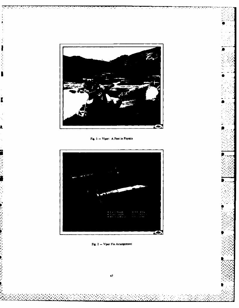
SOME DYNAMICAL ASPECTS! O4 MY ISSILESE ................................................. ............. 43- Dr. James J. Riardson. ChiiiStuclies and-Wchanics, U.S. Armay Missile Command,
Redstone Arsenal, AL
-AIR FORCE SPACE TECHNOLOGY CENTER SPACE TECHNOLOGY - EMPHASIS 84 ........................... 55~' Colonel Frank 1. Redd, Vice Commander, Air Force Space Technology Center, Kirtland AFS, NM
'- RFECIOS T~NDA .. A Y.sfEAVY'SARSPECTIVE'. .............. 59--* Her .Ps, osla KF Eninee ng ssociates, Inc., Vienna,
ELIAS KLEIN MEMORIAL LECTURE- MODAL WTINGJ.-14 CRITICALXE VIEW) ...... 1................. 65 4
Strether Smith, Lockheed Palo Alto Reerh boratofjr,'lo Alto, CA
Dr. George Morosow, Ma?{in Marietta Cbrporation, Denver, CO -1-Nm
/iERE IS THE REAL LITERATURE ON AIRBLAST AND GROUND SHOCK?'..................................... 83Dr. Wilfred E. Baker, Southwest Research Institute, San Antonio, TX
MIL-STD-81IOD
3AILORING IWIIlATIVESA#OR MIL-STD-8101) ENVIRONMENTAL TEST NJtETHODS AND5 NGINEE ING %~UlDELNE. ...... 87
DavidL.ErsArFre; ht.e-ro--au-t--a.. L. Ear-rbAir Frce Wajh Aeonaurticaleaboratories W.rigs ht-.Patt er so-n. A F B, O... H............
SH. Caruso andE. Szymbdwjiak, Westinghouse Electric Corporation, Baltimore, MD
IMPACT.PF SIOUON DYNAMIC TEST LABORATORIES ; .............................................................. 1014' Dr. Allen T Curfis, Hughes Xircraft~ompany, El Segundo, CA
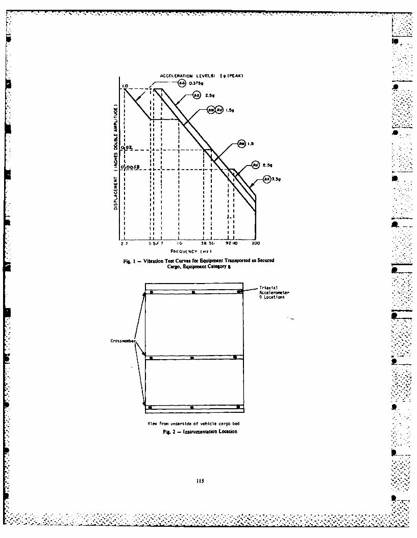
,rHE CHANGING.IBRATION SIMULATIONFYORjdILITARY gROUND V EHICLES*a............................. 113
*iakRobin~i, Materials testing Directorate, Xberdeen Pt ing Groul , MD
TWO-DIMENSIONAL SHOCK RESPONSE OF A MASS ON ENERGY-ABSORBING SHOCK MOUNTSR. E. Fortuna and V. H. Neubert, The Pennsylvania State University, University Park, PA
OPTIMUM DESIGN FOR NONLINEAR SHOCK MOUNTS FOR TRANSIENT INPUTSK. Kasraie, Firestone Tire & Rubber Company, Central Research Laboratories, Akron, OH and V. H. Neubert,The Pennsylvania State University, University Park, PA
THE DEVELOPMENT OF A METHOD FOR THE SHOCK-RESISTANT SECURING OF LARGE BATTERIESIN SUBMARINES
A. Jansen, Royal Netherlands Navy, The Hague
SHIPBOARD SHOCK RESPONSE OF THE MODEL STRUCTURE DSM; EXPERIMENTAL RESULTS VERSUSRESPONSES PREDICTED BY EIGHT PARTICIPANTS
R. Regoord, TNO-IWECO, Delft, the Netherlands 0
DIRECT ENERGY MINIMIZATION APPROACH TO WHIPPING ANALYSIS OF PRESSURE HULLSK. A. Bannister, Naval Surface Weapons Center, White Oak, Silver Spring, MD
Shock
WATER IMPACT LABORATORY AND FLIGHT TEST RESULTS FOR THE SPACE SHUTTLE SOLID ROCKETBOOSTER AFT SKIRT
D. A. Kross, NASA/Marshall Space Flight Center, Marshall Space Flight Center, AL, N. C. Murphy, United SpaceBoosters, Inc., Huntsville, AL, and E. A. Rawls, Chrysler Corporation, New Orleans, LA
AN OBJECTIVE ERROR MEASURE FOR THE COMPARISON OF CALCULATED AND MEASURED TRANSIENTRESPONSE HISTORIES
T. L. Geers, Lockheed Palo Alto Research Laboratory, Palo Alto, CA
ALTERNATIVE SHOCK CHARACTERIZATIONS FOR CONSISTENT SHOCK TEST SPECIFICATIONT. J. Baca, Sandia National Laboratories, Albuquerque, NM
SHOCK RESPONSE ANALYSIS BY PERSONAL COMPUTER USING THE EXTENDED IFT ALGORITHMC. T. Morrow, Consultant, Encinitas, CA ,- - "
LEAST FAVORABLE RESPONSE OF INELASTIC STRUCTURESF. C. Chang, T. L. Paez, and F. Ju, The University of New Mexico, Albuquerque, NM
LOW VELOCITY, EXPLOSIVELY DRIVEN FLYER PLATE DESIGN FOR IMPACT FUZE DEVELOPMENT TESTINGR. A. Benham, Sandia National Laboratories, Albuquerque, NM
EXPERIMENTAL INVESTIGATION OF VIBROIMPACT OF TWO OSCILLATORSC. N. Bapat and S. Sankar, Concordia University, Montreal, Quebec, Canada
MODELS FOR SHOCK DAMAGE TO MARINE STRUCTURAL MATERIALS SD. W. Nicholson, Naval Surface Weapons Center, White Oak, Silver Spring, MD
A STUDY OF THE EFFECT OF MASS LOADING ON THE SHOCK ENVIRONMENTQ. Z. Wang, Be ing Institute of Strength and Environment Engineering, Beijing, China and H. B. Lin,Chinese Academy of Space Technology, Beijing, China
Blast and Ground Shock .
ASSESSMENT OF SEISMIC SURVIVABILITYR. E. McClellan, The Aerospace Corporation, El Segundo, CA ". *".',.*
GROUND SHOCK EFFECT ON SOIL FIELD INCLUSIONS , ..- ,:b q
R. E. McClellan, The Aerospace Corporation, El Segundo, CA
PENETRATION OF SHORT DURATION AIRBLAST INTO PROTECTIVE STRUCTURES 0J. R. Britt and J. L. Drake, Applied Research Associates, Southern Division, Vicksburg, MS
iv
A COMPUTATIONAL PROCEDURE FOR PEAK INSTRUCTURE MOTIONS AND SHOCK SPECTRA FOR LCONVENTIONAL WEAPONS L
S. A. Kiser, J. P. Balsam, and J. T. Baylot, USAE Waterways Experiment Station, Vicksburg MS
PRELIMINARY DESIGN CRITERIA AND CERTIFICATION TEST SPECIFICATIONS FOR BLASTRESISTANT WINDOWS
0. E. Maeys, W. A. Keenan, and N. F. Shoemaker, Naval Civil Engineering Laboratory,Pont Hueneme, CA
PAPERS APPEARING IN PART 3
Stmual Dznami
STRUCTURAL MODIFICATIONS BY VISCOELASTIC ELEMENTSP. J. Riehle, Anatrol Corporation, Cincinnati, OH
STOCHASTIC DYNAMIC ANALYSIS OF A STRUCTURE WITH FRICTIONAL JOINTSQ. L. Tian and Y. B. Liu, Institute of Mechanics, Chinese Academy of Sciences and D. K. Liu,Spae Science A Technology Centre, Chinese Academy of Sciences, Seft, China
MODAL ANALYSIS OF STRUCTURAL SYSTEMS INVOLVING NONLINEAR COUPLINGR. A. Ibrahim, T. D. Woodall, and H. Heo, Department of Mechanical Engineering, Teoas Tech University,Lubbock, TX
DISCRETE MODIFICATIONS TO CONTINUOUS DYNAMIC STRUCTURAL SYSTEMSY. Okada, lbralki University, Hitachi, Jam, B. P. Wang, University of Texas at Arlington, Arlington, TX,and W. D. Pilkey, University of Virginia, Charlottesville, VA
REANALYSIS OF CONTINUOUS DYNAMIC SYSTEMS WITH CONTINUOUS MODIFICATIONSB. P. Wang, University of Texas at Arlinton, Arlington, TX, Y. Okada, Ibaraki University, Hitachi, Japan, andW. D. Pilkey, University of Virginia, Charlottesville, VA
A POLE-FREE REDUCED-ORDER CHARACTERISTIC DETERMINANT METHOD FOR LINEAR VIBRATIONANALYSIS BASED ON SUB-STRUCTURING
B. DawIon, Polytechnic of Central London, London, England, and M. Davies, University of Surrey,Guildford, Surrey, Ensland
DETERMINATION OF SHEAR COEFFICIENT OF A GENERAL BEAM CROSS SECTION BYFINITE ELEMENT METHOD
C. M. Friedrich and S. C. Lin, Westinghouse Electric Corporation, Bettis Atomic Power Laboratory,West Millin, PA
M*.. :.w
GEAR CASE VIBRATION ISOLATION IN A GEARED TURBINE GENERATOR -.
R. P. Andrews Westinghouse Electric Corporation, Maine Division, Sunnyvale, CA .
EFFECT OF COUPLED TORSIONAL-FLEXURAL VIBRATION OF A GEARED SHAFT SYSTEM ON THEDYNAMIC TOOTH LOAD
S. V. Neriya, R. D. Dhat, and T, S. Sankar, Concordia University, Montreal, Quebec, Canada
PERCISION MEASUREMENT OF TORSIONAL OSCILLATIONS INDUCED BY GEAR ERRORSS. L. Shmuter, Ford Motor Company, Manufacturing Processes Laboratory, Dearborn, MI -. -
THE ANALYSIS DY THE LUMPED PARAMETER METHOD OF BLADE PLATFORM FRICTION DAMPERSUSED IN THE HIGH PRESSURE FUEL TUUBOPUMP OF THE SPACE SHUTTLE MAIN ENGINE
R. J. Dominic, University of Dayton Research Institute, Daymn, OH
9.-..-...p,. :-.-.
v
, *'
IL %kA -.f-f :&R
Vibration Problems
TRANSIENT VIBRATION TEST CRITERIA FOR SPACECRAFT HARDWARED. L. Kern and C. D. Bayos, Jet Propulsion Laboratory, California Institute of Technology, Pasadena. CA I
VIBRATIONAL LOADING MECHANISM OF UNITIZED CORRUGATED CONTAINERS WITH CUSHIONSAND NON-LOAD-REARING CONTENTS
T. J. Urban'k, Fores Products Laboratory, USDA Fores Service, Madison, WI
LEAKAGE-FLOW INDUCED VIBRATIONS OF A CHIMNEY STRUCTURE SUSPENDED IN A LIQUID FLOWH. Chung, Components Technology Division, Argonne National Laboratory, Argonne, IL*
THE EXPERIMENTAL PERFORMANCE OF AN OFF-ROAD VEHICLE UTILIZING ASEMI-ACTIVE SUSPENSION .
E. 3. Krasnicki, Lord Corporation, Erie, PA
EFFECT OF AIR CAVITY ON THE VIBRATION ANALYSIS OF LOADED DRUMSS. Do. National Research Institute, W. Bengal, India
AS
J.. a
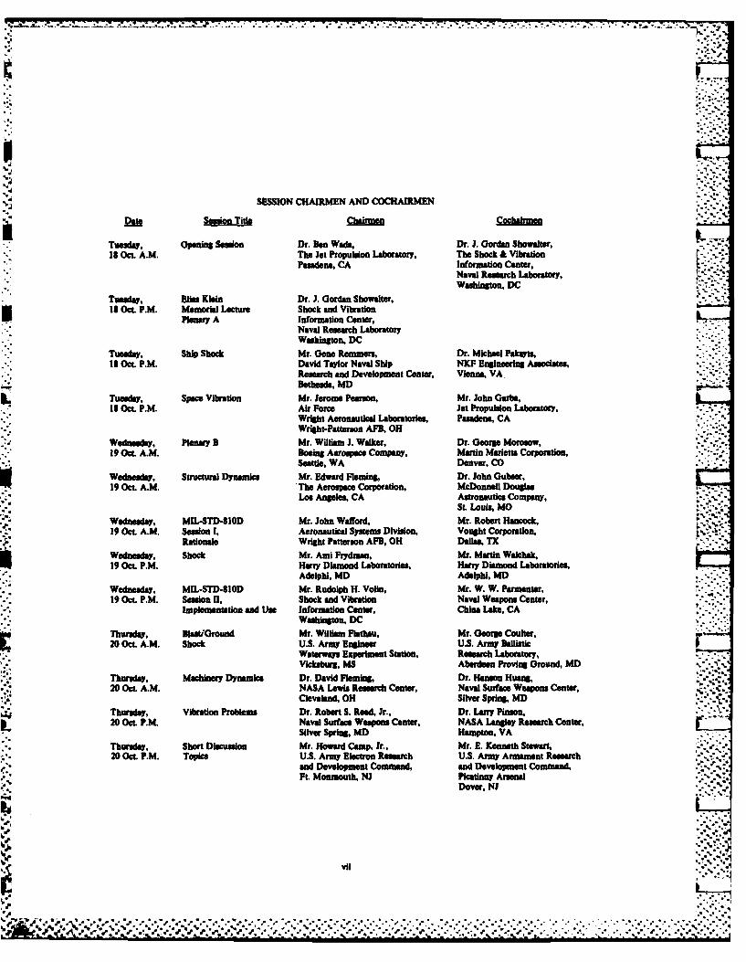
SESSION CHAIRMEN AND COCHAIRMEN
Date Session "i CDC
-Tuesda, opningSession Dr. Den Wads, Dr. J. Gordan Showalter.18 Oct. A.M. The Jet Propulsion Laboratory, The Shock & Vibration -
Pasadena, CA Information Cter,
Washington, DC
Tuesday, Ei. Klein Dr. J. Gordan Showalter,18 Oct. P.M. Memorial Lecture Shock and Vibration
Plenary A Information Center,Naval Research LaboratoryWuhington, DC
Tuesday. Ship Shock Mr. G ne Remmers, Dr. Michael Pakyts,13 Oct. P.M. David Taylor Naval Ship NKF Engineering Associates,
Research and Development Center, Vienna, VABethesda, MD
Tuesday, Space Vibration Mr. Jerome Pearson, Mr. John Garba,18 Oct. P.M. Air Force Jet Propulsion Laboratory, ..-.
Wednesday, Plenary B Mr. William J. Walker, Dr. George Moroow,19 Oct. A.M. Boeing Aerospace Company, Martin Marietta Corporation,
Seattle, WA Denver, COWednesday, Stuural Dynamics Mr. Edward Fleming, Dr. John Gubser,19 Oct. A.M. The Aerospace Corporation, McDonnell Douglas . -
Los Angeles, CA Astronautics Company,St Louls, MO
Wednesday, MIL-STD-810D Mr. John Wafford, Mr. Robert Hancock,19 Oct. A.M. Session I, Aeronautical Systems Division, Vought Cporation,
FRationale Wright Patterson AFB, OH Dan., TXWednesday, Shock Mr. Ami Frydman, Mr. Martin Walchak,19 Oct. P.M. Harry Diamond Laboratories, Harry Diamond Laboratories,
Adeiphi, MD Adelphi, MD
Wednesday, MIL-STD-810D Mr. Rudolph H. Volin, Mr. W. W. Parmenter,19 Oct. P.M. Sesion II, Shock and Vibration Naval Weapons Center,
Implementation and Use Information Center, China Lake, CAWashington, DC
Thursday, Blas'Oround Mr. William Flathau, Mr. George Coulter,20 Oct. A.M. Shock U.S. Army Engineer U.S. Army Ballistic
Waterways Experiment Station, Research Laboratory,Vicksburg, MS Aberdeen Proving Ground, MD '
Thursday, Machinery Dynamics Dr. David Fleming, Dr. Hanson Huaing,20 Oct A.M. NASA Lewis Research Center, Naval Surface Weapons Center, -
Cleveland, OH Silver Spring, MD
Thursday, Vibration Problems Dr. Robert S. Reed, Jr., Dr. Larry Pinson,20 Oct P.M. Naval Surface Weapons Center, NASA Langley Research Center,
Silver Spring, MD Hampton, VA
Thursday, Short Discussion Mr. Howard Camp, Ir., Mr. E. Kenneth Stewart,20 Oct. P.M. Topics U.S. Army Electron Research U.S. Army Armament Research
and Development Command, and Development Command,Ft Monmouth, NJ Picatinny Arsenal
Mr. Robert J. Parks --- "Associate Director for Space Science and Exploration
Jet Propulsion LaboratoryPasadena. CA
I'd like to welcome all of you to Pasadena The GALILEO spacecraft, as you may beand to the Jet Propulsion Laboratory. I do this aware, is scheduled to be launched in 1986, andon behalf of Dr. Allen who is the Director of wll carry a combined Orbiter and Probe tothe Jet Propulsion Laboratory (JPL) and who Jupiter. It will send the Probe into the uppercould not be here this morning. In fact he is atmosphere of Jupiter down to about 10-20 bars,in the Soviet Union, and it would have been a and it will make the first direct measurement oflittle bit difficult to commute to the meeting that atmosphere. Then the Orbiter will staythis morning. On his behalf and on behalf of around for another 20 months or so and observeall the rest of us at JPL, we certainly do the planet, its many satellites and its unusualwelcome you here to what I'm sure will be a very environment.useful and productive session.
The design of the GALILEO spacecraft hasWe at JPL certainly are able to fully turned out to be quite challenging. In many
appreciate the importance of the activities that respects it is the most complex, or capable,you are undertaking, and we endorse these dual spin spacecraft that has been put togetherefforts completely. We want to do everything we so far. So we found quite a few engineeringcan to help out and support these activities. I challenges in putting it together and testing itam sure that arrangements have been well made, to make sure it is all right. But it is in thatand I don't anticipate any problems, but phase right now, and as far as I'm aware, it'sarrangements can be made to help with whatever been going very well.turns out to be needed. Probably the biggestcontribution is that Ben Wads has been able to Although I understand most of theplay a role in putting all of this program unclassified sessions will be held here, theretogether. We are very pleased about that. is a series of classifed sessions which will be
held at JPL. I also understand that there is aBen mentioned how long I've been at JPL. planned visit to JPL on Friday for any of you
Over all those years, the kind of activity you who are able to make it. We certainly welcomeare discussing here this morning has been a key all of you and encourage all of you to visit ifpart of our space science and exploration it fits in with your plans. ..activities at JPL. The latest example of thisis the vibration, shock, and environmental Again, I would just like to say "Welcome"testing of a structural model of the GALILEO to all of you and give you our best wishes and
spacecraft, good luck in your further endeavors here. Thankyou.
Robert S. RyanGeorge C. Marshall Space Flight Center
Huntsville, Alabama
Good morning, ladies and gentlemen. It is thinking," a logical way to solve problems. .an honor and privilege for me to be here. I am What we need is a good case of lateral thinking,
6.. pleased to have the opportunity to address the a jolt to the side, that provides a new starting54th Shock and Vibration Symposium. I bring you point. From this new starting point, the oldgreetings from NASA and the Marshall Space standby, "linear thinking," again serves us InFlight Ce" er. We at NASA have supported this good stead. What is so hard for us togroup for many years, being involved in many accomplish is this lateral or side leap whichaspects of what you do. What an impressive provides the ideas for a new solution. Irecord you have! It is indeed my pleasure to be predict you will get many high voltage, laterala part of this meeting. With all the talents jolts while you are here. Specifically, I want
* assembled, I seriously question the merits of to talk to you today from the vantage point ofwhat I have to say, and yet for some reason, I NASA, where we have been, where we are, anddo have some things I really want to say. where we are going. First, from NASA's
viewpoint and then from the disciplinesThere are many definitions of what a associated with the Shock and Vibration
keynote address should be and what it should Information Group. This approach seemsaccomplish, so I went directly to the expert who compatible with your overall theme, "Oldinvited me here, Ben Wads, for the answer. Just Problems - New Solutions." We in space
* as I expected, he gave me an impossible task exploration need new solutions to old problems,delineating four objectives. Let me use Figure as well as new visions for future problems and1 to illustrate my guidelines. First, I must their solutions. I will not address thewake you up. Secondly, I should shake you up. aeronautics side of NASA, since it is not a partThirdly, I am to entertain you. Fourthly and of my experience base.finally, I am to soar you to new heights. Allto be accomplished in 30 to 45 minutes. Really, I. NASA - PAST, PRESENT and FUTUREthe task is achievable, but not by me. Theinformal discussions associated with being NASA is presently celebrating its 25thtogether in conjunction with the formal papers anniversary year, evolving from the NACAare th way these objectives are met. I am a organization which had its beginning in 1915.firm believer in the value of this yearly We at NASA have our roots firmly anchored inconvention and what it accomplishes. The theme aeronautics, which is still part of our .you have chosen is excellent, "Old Problems - charter. To fly was the first step toward spaceNew Solutions." and in a real sense could be the final step.
The agency was signed into law as a civilianThe ancient Greeks had a legend that every space agency by President Eisenhower on July 29,
five hundred years, the Phoenix, a mythical 1958. Most of us remember with vividness thebfrd, burst into flames and was reduced to shock of Sputnik that resulted in NASA'sashes. From these ashes, the Phoenix bird rose birth. My first sighting of Sputnik came nearagain, renewed in youthful vigor. Although this sunset with such an impressive glow that it is ...is only a legend, in actual life we have found still etched clearly in my mind. We haveit necessary to begin again with little more accomplished much as a government/industry teamthan the ashes of the past, rising to new in those 25 years, resulting in an impressiveheights with great vigor. I do not believe we technology resource for our nation. The thrillare in the position of having only ashes left of space exploration has not diminished. Each ." *"
from the past; however, the principles of a new new achievement brings renewed emotional peaks,start anchored in the past is very sound. not only for us involved but for the public in
"- Meetings like this serve this purpose well. We general. MSFC received more letters, etc.,
are away from the job, home, etc., which puts us after STS-8 flew than from any previousin a good psychological state for new visions of flight. Time will permit looking at only a fewsolutions to old problems. By training, we are snapshots of these accomplishments. Figure 2trapped in the very effective method of "linear summarizes to some extent where we have been.
3
. i. ..-.4....--''
'" .%
•' o '. '. .'/% -.°* *° * ',*° . ,° " ' "." oo-- .'°. o "
" ° • . . ° . • •..o o . °° .° , ° t~ = • o. .o%°
WAKE YOU UP SHAKE YOU UP
4bB
SOAR YOU TO NEW HEIGHTS ENTERTAIN YOU
Fig. I -Objetives of a Keynote Address
WHERE HAVE WE BEEN ?
* .It.
SAUR
ATLAS-
.."
-. . . . ..
-. 7 - - -
In the center is listed most of the launch The first Spacelab mission flies this monthvehicles used with some of the key programs or with two other Spacelab missions to followpayloads on the perimeter. In the right-hand shortly. Spacelab is one of our laboratoriescorner is the Shuttle development looming at us for utilization of space. Many options are
. as an extension of the earlier vehicles, available for various experiments and space
obviously more recently but still in our past as exploration. Work is in progress on the Westernfar as development goes. Let us not dwell on Test Range facilities with the first Spacethese accomplishments, nor how we overcame many Shuttle launch scheduled there within two
*difficulties, setbacks, and problems. Briefly, years. Space Telescope is progressing towards awe should recall the grandeur, excitement, 1986 launch, providing scientists with theirnational prestige, and even more importantly, greatest opportunity yet to explore our - -'
the fresh look at our planet Earth that universe. The technical challenges associatedaccompanied them. Just to refresh your memory, with designing, verifying, and operating aFigure 3 was made when we were just into early telescope of this nature is mind boggling.
" Shuttle development and in the middle of Pointing accuracy, length of operations time,* Skylab. Emphasized are Marshall Space Flight etc., are unprecedented. The Long Duration
Center's management roles. Snapshots of the Exposure Facility is moving steadily towardsLunar Rover, Saturn, HEAO, Skylab and Shuttle launch. A solar wing (SAFE), forerunner ofare shown, space power, will be launched within 18 months,
including for the first time "on-orbit" dynamic SApollo, with the lunar landing and lunar testing using remote sensors. Tracking Data
. exploration, was indeed one small step for man - Relay Satellites are in orbit and are going inone giant leap for shock and vibration. Apollo orbit to serve space as well as mankind.
• was composed of 11 manned flights involving 29 Special missions are moving ahead rapidly.astronauts, 12 of whom placed their footprints Also, many get-away specials can be flown onon the Moon. In addition, there were two manned Shuttle on space availability status. These areEarth orbit preliminaries, three circumlunar experiments that can be quickly installed or
* flights, and six lunar landing missions. The substituted as space becomes available. Theresults of Mariner (1978), Pioneer (1978), facilities and procedures are developed andViking (1976), Voyager (1977), again raised us working at KSC for Shuttle payload processingto new heights, providing new insights into our and integration with the Orbiter. Routine spaceuniverse and our origins. The people here at operations using the Shuttle are here.JPL can better tell these stories, althoughemotionally and in some special cases With that brief snapshot of where we are,technically, we shared together. Skylab (1973) let's look at where we are going. The Presidentwas our first orbiting space station (Figure last year delineated a space policy, and NASA
" 4). Out of near disaster came the highly has formulated a set of goals and objectives to. successful exploration of Earth and beyond, carry out this space policy. Figure 8 lists
telescope, materials processing, earth these goals. Specific objectives have beenresources, containing three missions of 28, 59, developed for each of these goals.
- and 84 days, proving the resiliency andnecessity of man in space. Clearly, the keys are man's presence in
space, low-cost Shuttle operations, spaceSpace Shuttle Columbia lifted off the pad science, space technology, and aeronautics.
in 1981 (Figure 5) followed by 7 more flights, 5 Coming out of the pack as a focus for some ofof which were dubbed developmental, while the these goals is the Space Station (Figure 9).last 3 were operational. With this step, man You will be hearing much about this in thehas the capability to routinely and efficiently future. Obviously, a major focus is making the
*enter space. Shuttle operations routine and cost effectivewith all this implied.
Squeezed in between, from Marshall'sviewpoint, were the three HEAO missions (Figure If one looks at the goals and what is in -6) launched using Air Force vehicles adding the works, many exciting possibilities are ingreatly to our scientific knowledge. Briefly, various stages of ideas, plans, orthis is where we have been -- to the Moon, the development. Figure 10 lists some of theplanets, and beyond, using efficiently both various areas of the goals we are committedmanned and unmanned space exploration, to. We are working the upper stages as a means
of higher orbits and planetary missions.The next question peeking over the horizon Utilization of the Shuttle for experimentation
is, "Where are we today with the Shuttle in all forms from get-away specials to Spacedevelopment behind us?" A record of eight Telescope are key areas. Many orbitingsuccessful Space Shuttle launches and number 9 observatories from IRAS to AXAF are moving(Spacelab 1) ready for launch later this month forward and offer exciting potentials. Galileois in the books. We jointly are in full swing will be with us shortly as will the Tetheredwith the next phase, "utilization of space," Satellite. Spacelab will he a major activitywith the Space Shuttle the work horse. Figure 7 for many years. Shuttle performance
- illustrates some of the activities we are into • improvements are a continuing goal. Planning. now or will he very shortly. boards already have many concepts for large lift
* PROVIDE FOR OUR PEOPLE A CREATIVE ENVIRONMENT AND THE BEST OFFACILITIES, SUPPORT SERVICES. AND MANAGEMENT SUPPORT SO THEY CANPERFORM WITH EXCELLENCE NASA'S RESEARCH, DEVELOPMENT, MISSION, ANDOPERATIONAL RESPONSIBILITIES.
* MAKE THE SPACE TRANSPORTATION SYSTEM FULLY OPERATIONAL AND COSTEFFECTIVE IN PROVIDING ROUTINE ACCESS TO SPACE FOR DOMESTIC ANDFOREIGN, COMMERCIAL AND GOVERNMENTAL USERS.
W ESTABLISH A PERMANENT MANNED PRESENCE IN SPACE TO EXPAND THEEXPLORATION AND USE OF SPACE FOR ACTIVITIES WHICH ENHANCE THE SECURITYAND WE LFARE OF MANKIND.
* CONDUCT AN EFFECTIVE AND PRODUCTIVE AERONAUTICS PROGRAM WHICHCONTRIBUTES MATERIALLY TO THE ENDURING PREEMINENCE OF U. S. CIVIL ANDMILITARY AVIATION.
W CONDUCT AN EFFECTIVE AND PRODUCTIVE SPACE SCIENCE PROGRAM WHICHEXPANDS HUMAN KNOWLEDGE OF THE EARTH. ITS ENVIRONMENT, THE SOLAR
SYSTEM. AND THE UNIVERSE
* CONDUCT EFFECTIVE AND PRODUCTIVE SPACE APPLICATIONS AND TECHNOLOGYPROGRAMS WHICH CONTRIBUTE MATERIALLY TOWARD U. S LEADERSHIP ANDSECURITY
* EXPAND OPPORTUNITIES FOR U S PRIVATE SECTOR INVESTMENT ANDINVOLVEMENT IN CIVIL SPACE AND SPACE-RELATED ACTIVITIES.
- ESTABLISH NASA AS A LEADER IN THE DEVELOPMENT AND APPLICATION OFADVANCED TECHNOLOGY AND MANAGEMENT PRACTICES WHICH CONTRIBUTETO SIGNIFICANT INCREASES IN BOTHA AGENCY AND NATIONAL PRODUCTIVITY.
Fig. 8 - NASA Goals End Objectives
S%
-" o
%
. ...- :..-...-
WHERE WE ARE GOING
Fig. 9 - Future Space Programs - Space Station
* UPPER STAGES FOR HIGH ORBITS AND PLANETARY EXPLORATION
* IUS
* CENTAUR
* OTV* PAM
* GETAWAY SPECIALS ..
* STUDENT EXPERIMENTS
* SPACELAB
* SPACE POWER SYSTEM
* TETHERED SATELLITE
* SPACE STATION* PLANETARY
* GALILEO
* COMET STUDIES
* INTERNATIONAL HALLEY WATCH IIHW)
* ISEE -3
* SPACE TELESCOPE
* ORBITING OBSERVATIONS
* INFRARED ASTRONOMICAL SATELLITE (IRAS)
* SHUTTLE INFRARED TELESCOPE FACILITY ISIRTF)
* COSMIC BACKGROUND EXPLORER (COkE)
0 GAMMA RAY OBSERVATORY (GROI
* ADVANCED X-RAY ASTROPHYSICS FACILITY (AXAF)
* GLOBAL ENVIRONMENT* ACTIVE MAGNETOSPHERIC TRACER EXPLORERS
launch vehicles and Shuttle derivations. This illustrates this situation for the Space Shuttlethumbnail sketch completes our survey of NASA. Main Engine, where the latter approach was taken
when the enginer performance requirements wereII. SHOCK AND VIBRATION - PAST, PRESENT AND upped nine percent to meet additional SpaceFUTURE Shuttle performance requirements. All essential
elements of the lifetime problem are shown. KeyI would like to turn to the technical areas to solving the SSME fatigue issues has been
you are most concerned with, viewing them from threefold, (1) structural dynamic test (model
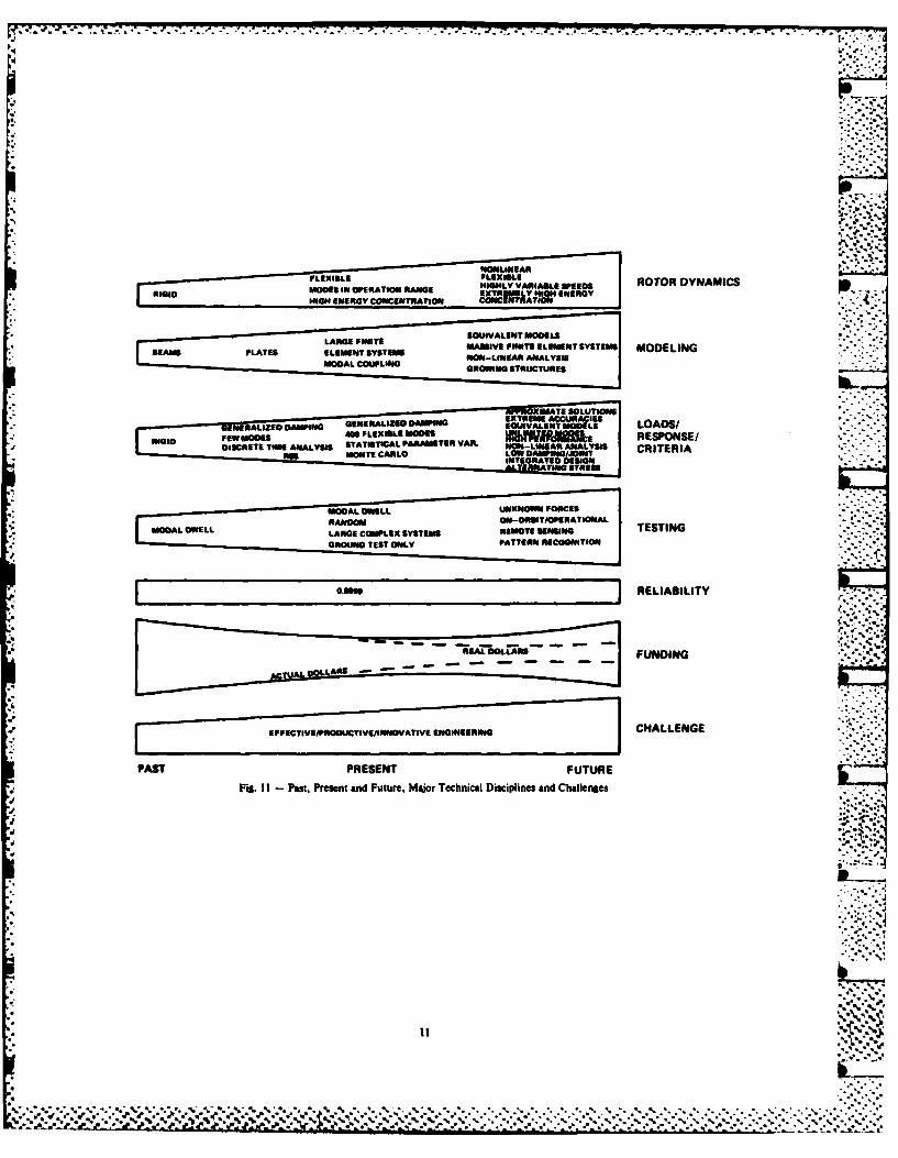
my vantage point as a structural dynamicist, who verification), (2) materials selection andhas spent many years working the control material properties characterization, and (3)disciplines. Clearly, we in the technical hot firing ground test enviromment and responsedisciplines associated with shock and vibration measurements, lifetime verification beingface our greatest challenges. Visions of the accomplished through the hot firing groundfuture with a firm understanding of where we are certification program. Very accuratenow and where we are to focus are mandatory if predictions and their verification were the keywe are to meet the goals/objectives of our great to getting the Shuttle at the operational stageorganizations and our commitment to excellence it is at today.and the future of mankind. Figure 11 attemptsto answer in visual form where we have been, Figure 15 treats the area of componentwhere we are now, and where we are going. The criteria in more detail. Here, we have gonechart has three messages: first, it shows how from a limited data bank, single-axis prototypesome of the major technical disciplines are testing approach to the future, requiring multi-becoming more and more complex, pushing the axis with accelerated time testing. Data banksstate-of-the-art or beyond; second, and possibly must be extended to three dimensions. Analysiseven more important, it shows that we must solve must consider multi-3D modes instead of single-these technical challenges with less money and axis, single modes as well as alternateschedule time, while maintaining the same basic approaches, such as SEA (statistical energy
level of reliability; and last, it says if we analysis). Pattern recognition will be a keyare to accomplish these two major challenges, development area in conjunction withmore complex systems at lower cost and schedule analytical/operational verification of manytime, with the same reliability, then we cannot subsystems and components. This results fromjust do it with bigger and bigger, faster and the large volumes of data with many parametersfaster computers. We must change our focus to that we must evaluate.
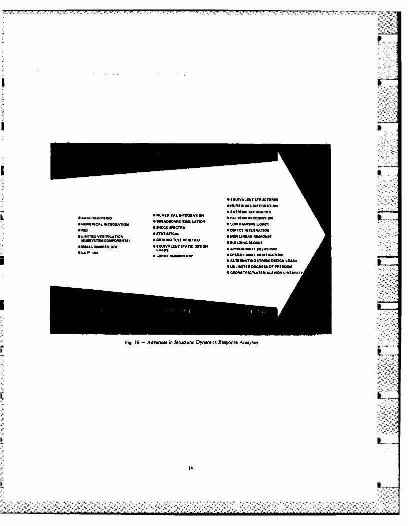
effective, productive, innovative engineering,which means fresh approaches to new problems. The area of dynamic response has made greatThis means new training methods, new management strides moving from rigid-body analysis totechniques, innovative organization patterns, limited number of elastic modes to the presentand simplified analysis and test techniques. Space Shuttle system response analysis of 400
modes, including wind, thrust parameters, "-" -I wish we had time to talk in detail about control, etc., in a Monte Carlo analysis (Figure
each of these 'discipline areas; we do not; 16). Approximately 30 parameters are varied inhowever, I have chosen only a few to look at and the analysis. Parallel with this is the verywill leave the main task to the experts in the accurate jitter analysis of optical systems,various sessions, which is really the purpose of such as Space Telescope where response of the
this conclave. In Figure 12 we see a more optical system to noise and control devicesdetailed description of structural dynamics from (momentum wheels) must be kept to very lowan overall viewpoint, providing additional values (arc milliseconds (0.0087)). Modesdetail over the previous slide. Key problem through 120 Hz are required for this analysis.areas are more accuracy, faster turn-around, In the future, unlimited number of modes inoperational verification, and special testing, conjunction with growing structures which are .High performance is a parallel complexity factor designed from stiffness will come into being.for these disciplines, particularly in terms of Many of these structures will be very complex,life-time which implies accurate environments, composed of many elements in an unsymmetricalmaterial characteristics, and fracture manner. Localized nonlinear damping willmechanics. The Shuttle Main Engine is an dominate the response creating new analysisexcellent example of this situation, high energy techniques as well as definition andconcentration, weight and volume constraints, verification techniques. Total system analysiswith high temperature and pressure. This with appropriate trades will be involved and isresults in high static or mean stress with very a major challenge.small allowances for alternating stress beforethe endurance limit Is reached. This implies Structural modeling has made great strides
that the high cycle alternating stress levels from both the analytical approaches and testingoperate on the flat part of the S-N curve, standpoint. Models have moved from equivalentcreating high sensitivity to small changes in beams to large finite element systems. Generalalternating stresses (Figure 13). Either one purpose finite element programs exist, such asmust reduce the mean stresses or increase the NASTAN, SPAR, and industry peculiar codes.endurance limit (material choice) to solve the Nonlinear and equivalent macro element modelingproblem or accurately predict the environments looms on the horizon (Figure 17). Testing of
and the dynamic characteristics. Figure 14 very large systems on the ground is now
Fig. I I - Pam,. Present and Future, Major Technical Disciplines and Challenges
5~%
c C . . ..r . ,. ...7
MODELING BEAMS TEST VERIFIED ANALYTICALIOFERATIONS VERIFIED 0LARGE NUMBER FINITE ELEMENTS NON-LINEARGENERALIZED DAMPING SUPER FINITE ELEMENT SYSTEMFIXED SYSTEM LOCAL/JOINT NON LINEAR DAMPING
GROWING STRUCTURE
ROTOR DYNAMICS RIGID HIGH ENERGY CONCENTRATION EXTREME ENERGY CONCENTRATIONFLEXIBLE NON-LINEAR FLEXIBLEMODES IN OPERATION RANGE HIGHLY VARIABLE SPEEDS
TIME KNOWN FORCE ON ORBIT/OPERATIONALMODAL DWELL J REMOTE SENSING
GROUND iFULL AND SCALE)
ENVIRONMENTS TEST TEST COMPUTATIONAL ANALYSISANALYTICAL APPROXIMATIONS OPERATIONAL ADJUSTMENTSNONDIMENSIONAL I "l
VIBRATION LIMITED SINGLE AXIS MULTI-AXISCRITERIA/TESTING DATA EXTENDED DATA BANKS TIME ACCELERATION
BASE LIMITED ANALYTICAL APPROACHES OPERATIONAL VERIFICATION "
PROTOFLIGHT
PAST PRESENT FUTURE
Fig. 12 - Overall View of Structural DynamiCs
GENERAL PROBLEM STATEMENT nN LIFETIME PREDICTIONS
CYCLES IN TOTAL CYCLES FOR1.0- SINGLE FIRING ENGINE DESIGN LIFE
0.6-
. ,-..,-
0.4
0.2-
102
105 10 107
CYCLES TO FAILURE
WEIGHT. VOLUME. SYSTEMS PERFORMANCE CONSTRAINTS, AND ENVIRONMENTS DO NOTALLOW DESIGN IELOW 'HE ENDURANCE LIMIT; THEREFORE. SMALL CHANGES IN ALTER--NATING STRESS CAUSE LARGE CHANGES IN LIFETIME
Fig. 13 - General Problem Statement of Lifetime Predictions
...:.-.
12
. . . . ...... ...... ...... C C C
* * *, *.'d2o * ." -. C,
7o -
W' i . *I .1I . II, "iI II - I . I li- ! I.1 - 1 1. . . . 'l 1t I I .I I.I ~ .I l iIIIi• * ." .'. .' *".". ." , •". . . . . . . . . . , . ","."-".".".". a . , . , . ..".".""".",".".. -"."'.-: " % "."' . . . . .% * % °" o . "o " '° ,% °. " " . . % ° ". % °w "-- 1 , " _' _ * % " . -. '. 'I_ " '. * "m % ", " % ,% _2 "
TEIUSEDTRANSENT EVIRO.I *FLOWACUTC ANLSSMDL A EVRFE
TESTINUCTRA SCNOERRELATION-MIIO
CRITERIAt LIMROTED DATAN SDATIALEMO
INST PLA (CURENTa FUUR.
DYNAMIC
FSTRU-AdaCTsUnViRoA utcCopnn riei 5
ENIOMN AH.OD/TE LFMOEL REITIN
STATICSTATI
THERMALEFFECS MAERIALPROPRTIE
ig. 4 -Spie Shttl Man EnineDynmic robemsand ethds or TeirSoltio
-~~~ STEAREMEACCUACILII NUIMITCA INTEFIRATION O PATTER REPONSEO
* ANALOGIGSLSRIDLOD* LAI tIRE UBRDO OERTOA VERIFICATION*NOLIERESNS
* ALTERNATING STRESS DESIGN LOADS
"UNLIMITED DEGREES OF FREEDOM
"GEOMETRIC/MATERIALS NON LINEARITY
.7
Fig. 16 - Advances in Structural Dynamics Response Analyses
14
routinely accomplished. The largest to date was 4. Qualification and verificatin usingthe full scale launch configuration of the Space protoflight (flight article) testing orShuttle. Many space configurations on the analytical verification moves us into a newplanning boards cannot be tested on the ground, regime.requiring analytical verification and/or on-orbit operational testing. Determination of 5. High performance induced problems, suchlocalized, joint damping for large space as lifetime and quality control.structures, in particular for fine pointing,high performance systems, will be required. Currently, we are attacking these problemsThis will be a major challenge. with finer models, larger, faster computers, "".
graphics, detailed statistical assessment, and pLet me move next to whnat are some very detailed testing. The challenge is to move to
basic and some new challenges I believe we face innovative approaches that use equivalentthat must be solved if the goals of NASA are models, integrated design, organizationmet. I believe many of these challenges also adjustments, and motivational and educational "transend into the various industries and programs.programs you are concerned wth.
Figure 20l illustrates this changingFuture space missions, in particular the approach for large space systems versus the p
satellites and the Space Station, move traditional. In the past, the structure wasconceptually into a more complex regime. Figure analytically characterized and test verified.18 illustrates this in two aspects, (1) design This structural model is used to design theapproaches and (2) expected lifetime. Notice in control system which is then test simulated. Asthe past, space vehicle designs were strength indicated with the arrows, feedback occursdesigned with large safety factors tested to between the various design and verificationacceptable limits and, in general, the activities producing a finely tuned and verifiedoperations time was short. In the present, we systems before it flies. Large space systemsare still in the strength design regime; cannot follow this traditional approach. Thesehowever, safety factors are limited. NDE and structures cannot be ground tested as a totalfracture mechanics are used. Fatigue is a unit. Only limited element tests can be .-
constant concern requiring much attention. Many performed. This means that the control designstructures are analytically verified instead of is accomplished using analytical models with " -test verified, particularly at the system verification accomplished in simulations. Thislevel. Operation time is still short with the means either the control system must be veryexception of a few spacecraft and satellites. complex, such as adaptive systems, so that it isFuture plans move from a strength design not sensitive to unknown or unpredictedapproach to systems that are designed for structural characteristics or the system must be - .-
stiffness, including very accurate control on changed on-orbit. To accomplish the latterdeformations and responses. Refurbishment and requires on-orbit structural dynamicmaintenance must constitute a prime part of the characterization with the ability of controlengineering tasks, integrated design approaches, system logic update to accommodate thesein conjunction with analytical and operational changing structural characteristics. The systemverification techniques. Figure 19 shows the is further complicated by the requirement fordilemma we have in structures/structural changing and growing configurations as missionsdynamics disciplines. The overall conflicting and uses evolve. This figure also illustratestechnical requirements of increasing cost, time, some of the concepts and programs now underway,complexity, and risks versus programmatic including two planned flight experiments, SAFErequirements of decreasing cost and time lead to and SADE.five major problems which must be solved in thenear future to meet near-term goals. Figure 21 illustrates some challenging
concepts for construction of these systems using1. Design loads cycle time/complexity, common elements in both volume and trusses.
One-year lead cycles must be reduced to Building block design and verification tools are ,..*..*
approximately three months or less if future a large part of concept as well as assembly *
Shuttle manifests are met. techniques. Many other options exist includingdeployables, erectables, on-orbit manufacturing
2. Payload experiments response accuracy (beam machines). The book is still open on the(loads) is a very real problem. Current approaches to be used. :, .-indications from first Shuttle flights indicate tthat experiment responses are being grossly As stated previously, the solutions to theoverpredicted. Analytical system models also challenges that are on the forefront of ourshow extreme sensitivities to small system disciplines must be solved in innovative ways.changes which are obviously incorrect. Computer graphics, computer-aided design, and
manufacturing, pattern recognition tools and3. Fine pointing requirements of systems, special software are some of the current
such as Space Telescope, antennas, etc., are techniques that need further development.requiring extremely accurate models and Figure 22 shows a graphics work station withknowledge of subsystems. special software that allows the engineer to
take computer-aided design tapes and build a
%"15 "•'-"
• o-°No
* EXTREMELY LARGE MULTI-BODY* ZERO I
* LARGE MULTI-BODY SYSTEMS 0 OPERATIONAL VERIFICATION
* LIMITED ZERO q. (IN ORBIT)
* SCALE MODEL AND FULL SCALE 0 TIME DOMAINS, RANDOM* SIMPLE SYSTEM a MODAL DWELL, SINE SWEEP, 0 NON-LINEAR
* MODAL OWELL IMPULSE, RANDOM, TIME GEOMETRICMATERIAL
* LINEAR 0 MODAL DWELL. SINE SWEEP.
* MODAL ORTHOGONALITY IMPULSE. RANDOM, TIME 0 HIGH ACCURACY
G GOODNESS CRITERIA FOR EACH * LOCAL NON LINEAR DAMPING" GENERALIZED DAMPING APPROACH 0 STIFFNESS AND STRENGTH DESIGN
Fig. 21 -Commonality of Spame Station Structure Elements
Fig, 22 - Computer Graphics Work Station
Ii
finite element structural model with the results sweat. Long is the raad thereto and steep andof a mass and stiffness matrix tape. Models rough at the first, but when the height is won,developed by subcontractors, etc., can be then is there ease." In all of this sweat,checked quickly for errors using this system, however, we need time to think, to meditate. WeObviously, these present systems are the need leisure for good ideas to work their waydoorways to exciting things in the future. into our consciousness. Remember, ideas can be
worth ten years of hard eight-hour-a-day work.teThe chart in Figure 23 summarizes some of Finally, whenever we have problems, we must *-
tetechnology gaps that exist in the rapidly follow the grand old rule, "Go back to theevolving field of structural control basics," a rule every athlete knows well. Youinteraction, a. discipline that is very exciting do not solve the game, lick the course, at best,and has a very special interest to me. Three you must keep playing and living with it anddiscipline areas are used, (1) structures, (2) going back to basics. Being a wood worker bycontrols, and (3) systems. Gaps are developed hobby has taught me repeatedly the lesson ofin three broad areas, (1) techniq~ses, (2) tools, basics, a lesson I believe applies to ourand (3) test (verification parameter data), engineering trade as well.Techniques deal with approaches to solving knownproblems, whereas tools describe techniques 1. Tools must be sharpened properly and
*required to apply the techniques. Teats deal in finely honed.a generic sense with verification. Generally,
*the areas discussed previously are contained in 2. Alignment must be very accurate,* this matrix. Readers can study it in detail for
more insight. Clearly, we must get ready for 3. Special jigs are mandatory tothis exciting mullti-discipline challenge to the accomplish many tasks correctly.future associated with apace stations and largespace structures. 4. Materials must be of highest quality.
Figure 24 summarizes some of the challenges 5. Work must be very accurately laid*that we face if the NASA goals and objectives out. Measure and remeasure again before*are to be met, Clearly, some of these cutting,
challenges as stated are controversial. Many*think we are already doing these things. To 6. Product must be hand rubbed and*some extent, I agree; however, It is a matter of polished to produce a fine finish.
degree. We must make further, larger steps if*we are to be successful. Organization structure Our answers lie, then, in (1) sweat, (2) leisure*must be under continuous evaluation if time for germinating ideas, and (3) a proclivity
integrated system design, etc., is for going back to the basics. I believe that Isaccomplished. Discipline-oriented organizations what this meeting is all about, so let's get oncan be a detriment to this type analysis. with it.Obviously, analysis time must be greatly reducedand productivity increased. Many would like to BIBLIOGRAPHYcontinue separate e,:ternal and internal loads
-analyses. We must re-evaluate this to see if we 1. Anderson, Frank, Jr.: Orders of Magnitude,do not need to remove this conservative approach NASA SP-4404, 1981
* by accomplishing dynamic stress analysis in lieuof using equivalent static external loads to 2. Haggerty, James: Spinoff 1983. Nationaldetermine internal stresses. We must greatly Aeronautics and Space Administration, ay-
*enhance our ability to do computational fluid 1983analysis, particularly in the area of internalflows such as rocket engines. More emphasis 3. The User's Guide to Spacelah Payloadmust be placed on designs that are amenable to Processing. NASA John F. Kennedy Spacemaintenance, growth, and quality control. Center, March 1983
Again, I want to emphasize the requirement 4. Levine, Arnold: Managaing NASA in thefor innovative pattern recognition techniques as Apollo Era. NASA SP-4102, 1982
* we deal with more and more data as a function of*ever increasing numbers of parameters. 5. Spitzer, Cary R. (Editor): Viking Orbiter
Information not interpretable is useless. Views of Mars. NASA SP-441, 1980* Payload analysis time must be cut by
approximately an order of magnitude as well as 6. Newell, Homer: Beyond the Atmosphere, Earlyimprovement in overall productivity. Years of Space Science. NASA SP-4211, 1980
-. With the chart on Figure 24, 1 close what 7. Schneider, William C. and Hanes, Thomas E.to me are some key challenges we face, Our (Editors): The Skylab Results, Advances inmajor task is defining the approaches for Astronautical Sciences. Americanmeeting these challenges. What Is the starting Astronautical Sciences. American
*point becomes the key question. A poet, Astronautical Society Publication, 1975- hundreds of years before Plato said, "Before the
gates of excellence, the high gods have placed 8. Life in the Universe, Proceedings of a
DAMPERS • STATE IDENTIFICATION * EICITATION* JOINT DAMPING * NONLINEAR * ACQUISITION -* AUXILIARY STIFFENING 0 GEOMETRIC " FORCING FUNCTION" DEFINITION OF PARAMETER a MATERIALS 0 NONLINEAR EFFECTS
VARIATION DATA BASE * JOINT DAMPING 0 GOODNESS CRITERIAo REMOTE SENSING 0 POINT LOADS 0 VERIFICATION OF TOOLS* REALTIME 1.D. • PARAMETER VARIATION & SENSITIVITY DATA DEFINITION
DEPINITION AND COMBINATION VERIFICATIONAREAS OF GAPS 0 GROWTH S GROUND SIMULATION OF ZERO .* PARAMETRIC DATA 0 TRANSIENT I. 0. AND DYNAMIC S JOB STRUCTURE
SYSTEMS 0 OPTIMIZATION APPROACHES 0 OPTIMIZATION APPROACHES 0 VERIFICATION OF STATISTICAL* BLENDING BETWEEN CONTROL (LARGE NUMBER OF MODES. COMBINATION APPROACHES
AND STRUCTURE COST CRITERIA, PERFORMANCE 0 VERIFICATION OF STRUCTURAL* DEFINITION OF PARAMETER CRITERIAI. CONTROL INTERACTION CONCEPTS
VARIATION DATA 0 STATIST4CAL COMBINATION* MEANS OF ACCOMMODATING APPROACHES
ORBITAL ENVIRONMENT DI$- I ON-ORBIT ENVIRONMENT CODESTURBANCE EFFECTS
* ROBUSTNESS (INSENSITIVE)
Fig. 23 - Technology Gaps in the Field of Structural-Control Interaction
* DESIGN FOR MAINTENANCE. REFURBISHMENT. GROWTH, QUALITY CONTROL ENHANCEMENT,AND NDE/FRACTURE MECHANICS.
* DESIGN AND VERIFICATION FROM AN INTEGRATED SYSTEM STAND POINT CONSIDERING ALLDISCIPLINES SIMULTANEOUSLY.
* INNOVATIVE ORGANIZATIONAL APPROACHES
* INNOVATIVE TRAINING APPROACHES/ENGINEERS KNOWLEDGEABLE INSEVERAL DISCIPLINES
* INNOVATIVE ANALYSIS TOOLS* SINGLE MULTI-DISCIPLINE SAFETY FACTOR B* MATERIAL SELECTION/COMPOSITES 0
G DESIGN SYSTEM TO BE FORGIVING AND ROBUST
6 DEVELOP INNOVATIVE PATTERN RECOGNITION AND EVALUATION TOOLS TO HANDLE LARGEDATA SETS ASSOCIATED WITH LARGE COMPLEX SYSTEMS 7
• DEVELOP APPROACHES FOR REPLACING QUASI-STATIC EQUIVALENT LOADS WITH DYNAMICSTRESS DESIGN LOADS
• REDUCE ANALYSIS TIME FOR PAYLOAD LOADS INTEGRATION BY FACTOR OF 3 TO 10
* EXTEND THE CAPABILITY FOR COMPUTATIONAL FLUID AND STRUCTURAL ANALYSISSIGNIFICANTLY
Fig. 24 - Challenges in Meeting NASA's Goals and Objectives
20
. . 2. '
.,.....,:".*' . P, *° . .*
7• -. -.7~ -,o
Conference held at NASA Ames ResearchCenter, Moffet Field, CA, NASA CP-2156, Dynamics. 20th Structures, StructuralJune 19-20, 1979 Dynamics, and Materials Conference, AIAA,
St. Louis, M0, April 4-6, 19799. Bilatein, Roger E.: Stages to Saturn, A
Technological History of the 26. Morosow, George; Dublin, Michael; andApollo/Saturn. NASA SP-4206, 1980 Kordes, Eldon E.: Needs and Trends in
Structural Dyunamics. Astronautics and10. Morrison, David: Voyages to Saturn. NASA Aeronautics, July/August 1978
SP-451, 1982 27. Garrick, I. E.; and Reed, II, Wilmer H.: S11. Fitzgerald, Jr., Paul E. and Gabris, Edward Historical Development of Flutter.
A.: The Space Shuttle Focused Technology AIAA/ASME/ASCE/AS 22nd Structures,Program: Lessons Learned. Astronautics and Structural Dynamics, and MaterialsAeronautics, February 1983 Conference, Atlanta, GA, April 6-8, 1981
12. Sackheim, Robert L. (Editor): Liquid-Rocket 28. Garrick, I. E.: Aeroelasticity - FrontiersPropulsion Technology. Astronautics and and Beyond. AIAA Journal of Aircraft,Aeronautics, April 1983 September 1976
13. Fitzgerald, Jr., Paul E. and Savage, 29. Ryan, R. S.; Salter, Larry; Young, GeorgeMelvyn: Cost as a Technology Driver. t., III; and Munafo, Paul M.: SSMEAstronautics and Aeronautics, October 1976 Lifetime Prediction and Verification,
Integrating Environments, Structures,14. Abrahamson, Lt. Gen. James A. (USAF): Materials, The Challenge. Space Shuttle
Shuttle Operational Expectations. from Challenge to Achievement Conference,Astronautics and Aeronautics, November 1982 Johnson Space Center, June 1983
15. Wilson, George C.: Space Program Lifting 30. Ryan, R. S. and Jewell, R. E.: AOff to New Regime. Astronautics and Preliminary Look at Control AugmentedAeronautics, July/August 1983 Dynamic Response of Structures. AIAA
Structures/Structural Dynamics/Materials16. Olstad, Walter: Targeting Space Station Conference, Lake Tahoe, Nevada, May 1983
Technologies. Astronautics and Aeronautics,March 1983
17. Future Space Transportation SystemsStudy. Astronautics and Aeronautics (4articles), pp. 36-56, June 1983
18. Moore, Jesse W.: Effective PlanetaryExploration at Low Cost. Astronautics andAeronautics, October 1982
19. Special Section on Interactive ComputerGraphics. Astronautics and Aeronautics,April 1983
20. Special Section on Space StationTechnology. Astronautics and Aeronautics,
March 1983
21. Diaz, Al and Casani, John R.: Galileo 1986on Centaur. Astronautics and Aeronautics,February 1983
22. Special Section on ArtificialIntelligence. Astronautics and Aeronautics(5 articles), July/August 1983
23. Keaton, Paul: Why Billions Can and Shouldbe Spent on Space. Astronautics andAeronautics, May 1983
24. Card, Michael F.: Trends in AerospaceStructures. Astronautics and Aeronautics,July/August 1983
25. Amos, Anthony K. and Goetz, Robert C.:Research Needs in Aerospace Structural
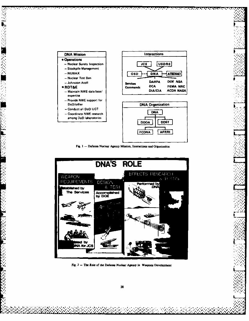
For those of you who are unfamiliar with Maryland, and they are concerned with thethe Defense Nuclear Agency (DNA), we are not biological effects of radiation.quite as well known as NASA, I would like to goover a brief introduction, and then I will Figure 2 depicts our role relative to thedescribe the DNA program having to do with the services and to the national laboratories. Webasing of primarily small missiles. The kinds do not develop weapons; they are developed byof basing we are talking about are hard silos the services. We don't build warheads; that isand hard mobile launchers. I will also include done by the Department of Energy. We considera few details from the Ballistic Missile Office the nuclear effects environment, theprogram since it is a parallel program. I vulnerabilities, and the lethalities ofshould also mention the whole program has some systems. Our primary role is effects researchfunding questions associated with it. I don't and testing. We also look for ways to improveknow if you follow the Congressional actions; the hardness of existing systems against nuclearthe House Appropriation Subcommittee deleted effects and possibly the directed energy effectssome resources from the Air Force program which of the future. Since we explore advancedcovers hard silos, and the Senate Appropriation concepts, we are mostly a technologySubcommitte kept them in. So now we are all organization.
waiting for full committees and joint committeesto get together to determine if what you are Within the organization of the Deputyabout to see will really take place to the Director for Science and Technology (DDST) isextent that I will point out. It is all beyond the Shock Physics Directorate which is made upour control. of three divisions (Fig. 3). The Hard Mobile
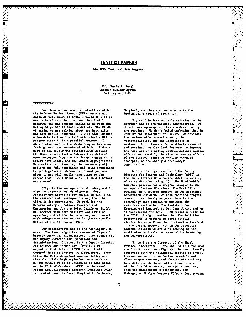
Launcher program has a program manager in the(Fig. 1) DNA has operational roles, and it Aerospace Systems Division. The Hard Silo
also has research and development roles, program has a program manager in the StrategicProbably two thirds of our budget is really in Structures Division. We have combined programthe research and development area; the other operation as closely as possible with thethird is for operations. We work for the technology base program to maximize theUndersecretary of Defense Research and resources available. The Assistant forEngineering and for the Joint Chiefs of Staff. Experimental Research is Dr. Gene Sevin, and heWe interact with both military and civilian is overviewing the total ICBM basing program foragencies; and within the services, we interact the DDST. I might mention that the Radiationwith subagencies such as the Ballistic Missile Directorate is working on small missileOffice of the Air Force (BMO). electronics as well as the electronics involved
in the basing aspect. Within the AerospaceOur Headquarters are in the Washington, DC Systems Division we are also looking at the
area. The lower right hand corner of Figure I small missile itself in terms of its hardeningbriefly shows our organization. DDOA stands for and vulnerability.the Deputy Director for Operations andAdministration. I report to the Deputy Director Since I am the Director of the Shockfor Science and Technology (DDST), I will Physics Directorate, I thought I'd tell you whatexpand on that later. FCDNA is our Field the Directorate does (Fig. 4). We are primarilyCommand which is located in Albuquerque. They concerned with the mechanical effects of shock,field the DOD underground nuclear tests, and thermal and nuclear radiation on mobile andthey also field high explosive tests such as fixed weapon systems, and that is why both theDIRECT COURSE which is scheduled to take place hard silo and the hard mobile launcher areon the 26th of October. AFRRI is the Armed within this Directorate. We also supervise,Forces Radiobiological Research Institute which from the Headquarter's standpoint, theis located near the Naval Hospital in Bethesda, Underground Nuclear Weapons Effects Test program
6/ 23
L._
at the Nevada test site as well as the high environments the missile may have to fly throughexplosives site. I mentioned DIRECT COURSE, and is a key problem within the small missilefor those of you who are not familiar with community.DIRECT COURSE, it is a one kiloton simulation ata scaled height of burst which will be conducted Of course, the question sometimes becomes,at White Sands. A sphere about 33 feet in "Why should DNA be so involved in developingdiameter and about 167 feet above the ground some of the silos?". An extract from the report... -will be filled with 600 tons of an ammonium of the President's Commission states that DNAnitrate and oil mixture explosive. It will have should have a major role in the basingnearly 200 major experiments in the area decision. It provides the impetus by which wesurrounding it. This event will occur on the are jointly working with the Air Force Ballistic 926th of October assuming we have no more Missile Office. If you look back at the DODlightning storms to destroy all of our authorization bill, you will find that theyinstrumentation. (This was reference to a specifically identified money to be provided tolightening storm in September which destroyed a DNA by the Air Force since Congress wanted tolarge number of gages.) ensure that people from the technology base, who
are not specifically systems oriented, would beinvolved in the review and consideration of how
DNA ICBM BASING R&D PROGRAM hard you can make a basing system. It is a . .parallel program which is very closely
The basic objective of both the Air Force integrated with the Air Force; and they areand the Defense Nuclear Agency is to provide looking to DNA to provide information ondecision-makers with as much information as environments, simulation, and instrumentationpossible in selecting a basing mode within a development and techniques. We are talkingrelatively short period, something like three about superhard silos, but still you must haveyears. The two basing modes we are considering missiles and equipment inside that can withstandare silos and mobile hardened launchers for associated shocks coming through. At the same . S.small missiles. We are particularly interested time we are also considering low level pressuresin two things in regard to the silos. We are for a missile or a launcher that will be sittinginterested in how hard we can build them, and we on the ground. We must find a way to haveare also interested in the range of hardening to something with a missile on it survive an .- -see what is most feasible and cost-effective, appropriate overpressure environment.Just making it very hard is not the wholesolution; and of course, we don't know exactly We will have a program in advanced -how hard we can build them. In regard to mobile hardening technology for silos, and we aresmall missile launchers, we are primarily looking at what the future might hold. We areinterested in the hardened launcher itself. It considering ways of being clever about makingis important to realize that we are talking something hard against very high shocks or veryprimarily about the basing of small missiles for strong ground motion. That cannot be donethe present. But, should anyone want to cheaply with the current technology; and itconsider a larger missile, a small missile is cannot be done completely effectively with theroughly half the size of an MX. So everything current technology, so we are looking for betteris well within the scaleable range of science, ways to approach it.
Figure 5 shows a schematic of a generic _7small missile. The gross weight of the missile ADVANCED SILO HARDNESS R&D PROGRAMitself is only in the 30,000 pound range, andthis is Congressionally mandated. The range is Figure 6 is a summary of the majorabout 6,000 nautical miles; it is four feet in objectives of this program. I think the firstdiameter and 44 feet long. To handle this, the one, resolving uncertainties, is verysize of the silo is about 110 feet deep and important. Those uncertainties are primarily in •about 12 feet wide when you put the missile and the environment definition. One of the mostequipment into it. So the silo is considerably important considerations is the cratering. Thisbigger than the missile. In regard to the size is because we have gone from concern for mostlyof the mobile launcher itself, you could take an airburat to the point where we are concernedroughly two or maybe two and a half times this with surviving a ground burst. If a groundto get the total size of the vehicle with the burst occurs, and if it produces a large crater,launcher on it. how big is that crater? There is little point
in building a very hard silo if it will be -The biggest problem will be in the terminal within the crater because it will not survive if
guidance system as far as the missile itself is it is flipped over subjected to highconcerned. Basically, I think we know how to accelerations or moved completely out of firingbuild missiles since we have been building capability orientation by the ground motion. Somissiles for a long time; but if it will be a there are some problems that have to be resolvedsmall missile, you have to make it very with regard to the environment. Also, materialsaccurate, and a lot of effort will have to go problems are involved; how do you put thoseinto that. Now to mount all of these systems materials together into a structure that will -
within the missile and have them survive the survive the associated effects?
24 • .'...
% --
*J** . -U E I, U UElE-.t-
Besides the shell itself, or the silo, you Figure 7 also summarizes some of the thingshave to worry about the shock isolation that are being done in the environmentp area.system. Most of the work on the shock isolation We must simulate one to six kilobare, bothsystem will be done by the Air Force. This height of burst and surface burst. We areInitial program, by the way, Is to arrive at a concerned with the soils in the area where thesolution, or concepts which may resolve the silo will be located, and we are concerned withproblem, within about a 3-year period. That materials from which the silo is constructed.would yield information which would assist We are also interested in simulating groundsomeone in deciding how to base a missile before shock and cratering. We have a test program to
% they go into Full Scale Engineering Development develop what we call a cratering and related(FSED). Much of the work will then continue effects simulator, and this program will beduring the FSED period. As you know, the mobile going on for about the next two years. We have ,launcher concept is more popular with the a near source simulator in the Yuma ProvingCongress than this is. Everybody would like to Ground Area, which is the first part of thissee a mobile launcher, but it has Its test program, and hopefully it will go off "' -problems. It is a little more expensive, it sometime in December. I have already mentionedrequires more people, and it requires a little instrumentation, and that program is extensivemore space; but on the other hand, it guarantees in developing the proper instrumentation. Mostthat you will concentrate on a small missile, of the silo field testing will be done by BHI onThose may be some of the considerations. You intermediate and large scale structures, but wewill not have a large missile on the launcher, will do some testing on a 50 inch diameter silo
to develop new concepts. These are differences* From a techncial standpoint we will in the effects of air bursts and ground
evaluate any advance silo designs that we can bursts. I mentioned the problem of the silocome up with. We will develop simulators, and being in the crater earlier; however, the silothat raises another problem. We know how to being buried under a large amount of debrissimulate one kilobar; we have done that. We can presents another problem. How do you get the
* simulate one and one half kilobers, but we can missile out if you are covered over with 30 oronly simulate a part of the environment at one 40 feet of debris because you are still withintime. We do some simulation with high the lip area of the crater? The Air Force isexplosives. We do some simulation with working on that problem.
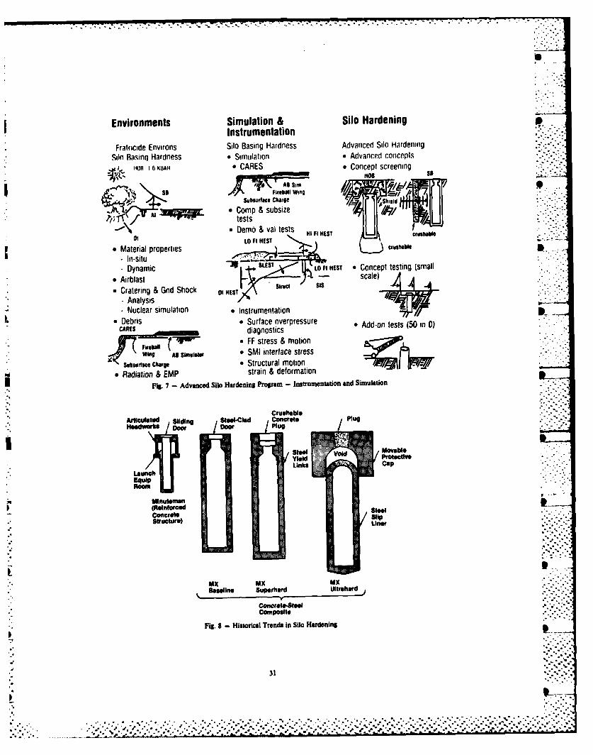
*i underground testing, and we do some simulation- with laboratory tests. But you can't put them Some historical trends in silo hardening
all together unless you can test in the are apparent (Fig. 8). These include theatmosphere, and I don't think that is in the Minuteman and the MX Baseline. Super hard iscards. just taking the baseline and putting a little
more steel in it and making some minor changesWe have to be able to measure what we find, to It. The ultra-hard silo is another possible
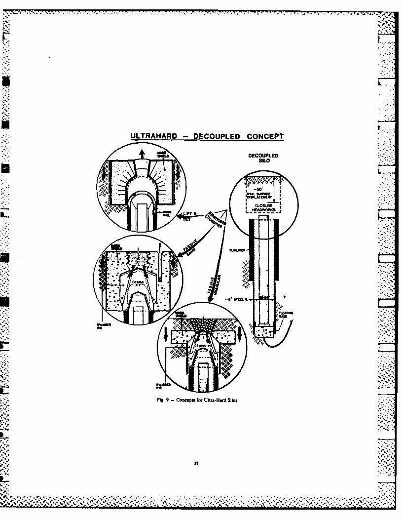
- and that is part of simulation and concept and we have done some testing. Aninstrumentation (Fig. 7). Within the simulation ultra-hard silo that has about 3% steel and adevelopment and the instrumentation development, liner inside was designed by Weldlinger andwe are having great difficulty with gauges being Karagozian. It was built at the Waterwaysable to measure the environment that we are Experiment Station, and it was tested there in 5actually creating. We are not sure of the November, 1982. By brute force, one can get upenvironment we are creating. The very high pretty high; but it is a matter of how muchpulse spike at the beginning of the air blast steel you put into it and how big you make it.
* simulation tends to wipe out the air blast (Fig. 9) Techniques are available for building* gauges. We can make some stress measurements, ultra hard silos. One idea is to decouple silos
but we are not sure how far you can back those from the ground motion, and it shows what to do. out. That is the way calculations are being with a silo if you are really clever and you
done. You look at the results of many of the want to isolate it from the shock, or have part Sexperiments that are going on now; and you think of the silo take the shock loading and beyou know what it is, but you are not sure how it destroyed while the rest of the silo survives.. " 'got there. If you have some other good ideas on how to
decouple structures in the ground from theI mentioned the cratering program; and I ground motion, we would love to hear about them. ..- ,,..
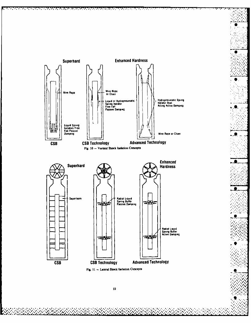
particularly want to point out that we hope togo back to the Pacific Proving Ground to I mentioned the shock isolation system. Wereexamine the craters, and try to understand how had some shock isolation mockups in some of ourthey were actually formed. Their formation tests. We used two types of shock isolators;mechanism will then go into the codes which we one was a spring-hydraulic type, and the otherwill use to either verify, deny, or argue with was a straight hydraulic type mounted either onthe calculations that we currently use. the silo wall or on the mockup of a cannisterRemember, I said the cratering Is most important inside. I mentioned earlier that the Air Forcein determining whether it makes sense to build a is looking at this program. They are doing avery hard silo. So we have a considerable lot of work on shock isolation systems; they areinvestment in that area. working primarily with Boeing. Figure 10 shows I
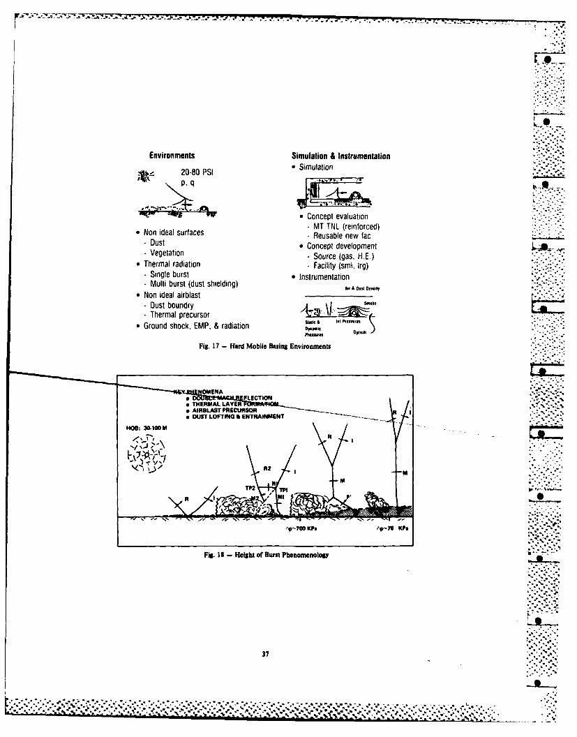
concepts. This shows the enhanced hardness and 500 on a mobile launcher; possibly all ofconcept, but we are going more toward the the missiles could be on mobile launchers, orsuperhard concept now. This is what is possible all of the missiles could be in the ground. Thewith advanced technology; hydropeumatic desired maximum speed capability of the hardenedsprings, dual isolators, and computer controlled transporters limits their size, and this limitsactive damping. Figure 11 shows some alternate their hardness. Many suspension problems onlateral shock isolation system concepts. At these transporters are also foreseen. Thesepresent we put lots of foam around the missile transporters will be located on a numbermissile. They are looking at ways of installing of bases within the United States, and they dorecoverable dampers so if you have more than one take up a large area. One of the main problemsshock, you will not end up with the crush-up on will be communicating with and controlling them. •the first blast taking away your capability foreliminating lateral shock. The Ballistics Next I would like to discuss the DNAMissile Office is considering the construction Hardened Mobile Launcher RLD Program. I mightof a shock isolation testing facility which mention that BMO will build a large blastwould be capable of doing a full scale test on facility. They would like to be able to test athe silo, at least at the small silo dimensions full scale hard mobile launcher. We are working(Fig.12). Again, I am not sure if it will be on the best way to develop such a simulator. --built now, but it was originally in the program The single most important factor in defining the .for the Air Force. environment is the nature of the non-ideal air
blast (Fig. 17). We are not sure whatAnother consideration for reducing the constitutes the non-ideal air blast. What is
ground shock motion is to do something before its magnitude? What are its effects? Manythe shock reaches the silo by putting some sort calculations have been made, but we have to make . .of barrier around the silo to absorb the ground some better measurements if we are to simulateshock (Fig. 13). This has been done it. Then we must be able to simulate it if wecommercially to protect pumping stations, for want to use it to test the launcher. Testing , ..example. We have even had the Steel Industry the launcher against the ideal situation is notvery interested, and the Steel Workers Union has satisfactory. So, first we are trying tosuggested putting a lot of iron pipes in the understand non-ideal air blasts; and second, weground and have the pipes act as dampers for the are looking for ways to simulate non-ideal air -'
shock. Obviously, this is only effective blasts. EMP will also be present; and for theagainst ground burst, (we are talking about most part, we will examine EMP environments atlateral motion and this has nothing to do with very low levels. We will not develop anythe overpressures coming down). The simulators for EMP until about the 1986 Seffectiveness varies considerably with the type timeframe. The Hard Mobile Launcher, if it is aof soils with which you are involved. Figure 14 system to be used, will not go into the fieldshows another possible concept; here the until probably the 1992 timeframe which iscrushable material would be a low porosity roughly when the small missile is supposed to be .-..concrete perhaps, available.
Some calculations were made using an There are many factors that contribute toanalytical model of a ground shock isolation the non-ideal air blast; these include the typesystem which was subjected to a 27 megaton field of surface that you are operating over, and howsurface burst (Fig. 15). Figure 16 shows the that interacts with the thermal and blastcalculations of the effectiveness of the three loading. It also includes the effects ofdifferent types of barrier that were studied, thermal radiation of boundary layers. We areWith no barrier, the stress was considerably concerned with the synergistic effects betweenhigher, but all of the barriers provided some EMP, radiation, and air blast since this systemreduction of the lateral ground shock. All of is above the ground and in an area where therethe foams were effective; in the case of is quite a bit of radiation. With the height ofvelocity, the foam delayed or reduced the burst type attack on a ground/surface target, avelocity considerably; and in the other case, as double Mach stem area occurs. You have thesoon as the foam got locked up, it just thermal precursor coming out, and you have a C.translated and delayed the time. However, the great deal of material picked up and entrainedtotal displacement appears to be relatively the and then becoming part of the air blast (Fi."same; it just takes place over a longer period 18). We are the most concerned with this area..of time, and therefore, the chance of protecting of the non-ideal cycle. We think we understandagainst the acceleration is that much better, this situation, but it is when you get into the -
Mach stem that you have an ideal typesituation. Still, there is a lot of material in
HARDENED MISSILE LAUNCHER R&D PROGRAM there that we have to be able to simulate. Thereason for the importance of the non-ideal air
The Air Force envisions the hard mobile blast is that the dynamic pressure of a non-basing concept as transporting a number of small ideal air blast seems to go up compared to themissiles randomly over base roads on hardened ideal air blast; while at the same time, thelaunchers. I do not know how many missiles overpressure is down in the same area (Fig.would be involved, possibly 500 in the ground 19). The combination can be more destructive.
26
.%.o.
,..
. o. oo o. .. .o,.......• - *..-... -- , oo .o. ...o - . . .-..-.. •
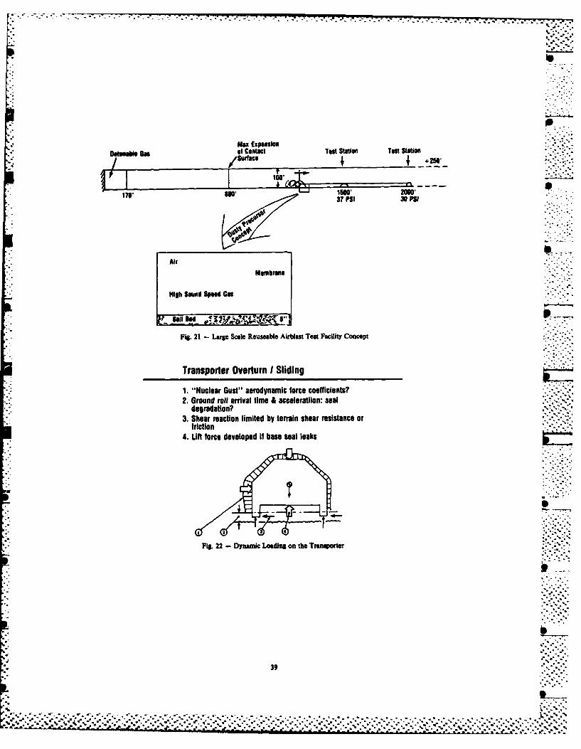
With the overpressure going down you cannot the overpressure is reduced at the same time thecount on the overpressure fixing or applying a lifting force will be considerably greater thanforce to hold the launcher in place. It goes the force on the top. Figure 23 demonstrates Adown at the wrong time, just about the same time the combination of the dynamic loading and thethat the dynamic loading occurs. overpressure change which results in the reduced
stability of the system. A great deal dependsWe would like to have ways of simulating on the shape. On DIRECT COURSE, we have four
these types of weapon effects (Fig. 20). The contractors testing different shapes, differentbars represent things that are relatively new or types of seals, and different dimensions; but Itthat we don't really know how to do. Dynamic is not clear that you can accurately scale those -Air Blast Simulators (DABS) are not new, but the features so the tests are not consideredsize of the Dynamic Air Blast Simulators and the definitive. They are just the first attempt topressure levels that we are talking about are do something on this height of burst test, andnew. We are even considering large cavity we expect to do more height of burst tests inunderground tests. We recently ran a cavity the future. Figure 24 shows some of the sealunderground test of about an 11 meter radius candidates which are being considered and alsocalled MINI JADE. We are considering running the idea of putting something underneath thesimilar tests using a nuclear driven shock tube; launcher which will anchor it to overcome thethat is a possibility. We are presently working sliding problems.to simulate a small scale air blast using amodified shock tube. This will be elevated into Figure 25 is a program schedule that showsan intermediate scale air blast simulation the DNA program feeding into the B4O programbefore we finally figure out how to do the full with our program concentrating on the firstscale air blast simulation, which could take a three years. We are providing this informationshock tube that might be 3,000 feet long. From to try to get a Full Scale EngineeringFigure 21 you will get the idea of the Development input, but our program will be --dimensions for a full-scale shock tube. In continuing at a reduced level from what it will .regard to simulating the precursor, if we cannot be during the first three years.put in the appropriate thermal loading on theground to cause a precursor to be formed, wemight be able to simulate that by using a high SUMMARYsound speed gas. None of the material from thedetonation should be allowed to reach the target We are considering both hardened silos andor to interfere with the measurements. Thus, mobile launcher@. We are trying to incorporatethe gas driver may have to be detonatable; it existing technology but we are looking for newmight be compressed air. A lot has to be concepts. Major problems are to reduce thedetermined; how do we build a large shock tube uncertainties in the environments and to developthat can be used a number of times? Building a the necessary simulation and instrumentation;
* large disposable shock tube each time is the bottom line is to prove that what we have. expensive; after you have done four shocks, you done is correct. All of this is concentrated in- have spent about 25 to 30 million dollars. For the first two years of the program. This is the
that same money, you can build a permanent shock third year. If you want to talk to anyone abouttube, or one that is partially permanent and these programs, the technical director for thepartially self destructive. Hard Silo is Dr. Kent Goering, and the te-hnical
director for the Hard Mobile Basing is Dr. PaulWith respect to the hard mobile basing Rohr. Both of those people are in the Shock
" hardening and validation, RMO has put out, or is Physics Directorate of the Defense Nuclear" putting out, a large number of contracts to Agency. That covers the DNA Program with a
about 5 contractors to develop new concepts. little of the 40 Program thrown in.They will go through about a 10-month period ofdeveloping new ideas. Then these ideas will benarrowed down to two, and they will go into alittle more full scale research program. Wewill review what Is going on, and we willprovide them with the environments, thesimulation capabilities, and theinstrumentation. We will also consider theeffectiveness of their hardening techniques, and
Swe will consider ways of hardening. Two of the
things we are concerned with are the rigid bodyresponse and how to overcome the dynamic loadingto keep the launcher on the ground. Figure 22
" shows the dynamic loading of the transporter.
Basically, we have a force which lifts upand possibly a ground motion effect. If theseal leaks, the dynamic loading comes in
underneath to force the transporter up, and if
27
..o. .
%7 V.
DNA Mission Interactions*Operations- Nuclear Surety Inspection JCS UD- Stockpile Management
- NUWAX OSD - DNA A1!DCAE
N - Nuclear Test Ban- Johnston Atoll Services DA A DO NA
*RDT&E Commands OCA FEMA NRC-Maintain NWE data base/ DIA/CIA ACDA NASAexpertise
-Provide NWE support for _________________
DoD/other DNA Organization-Conduct all DoD UGT-Coordinate NWE researchDNamong DoD laboratories
Fig. I - Defense Nuclear Agency Mission, Interactions and Organization
The. 2evc - heRoeoheenishe NcerAec nWepn eeo n
28
DDST Organization
i Asistal BarI fI'o~"' - -I Exermeta Th1"' 1MGI Reerh Tsig Aselsia
Ileehen a InfeAiatiJarhInealoratel STTI
Radi-anio in Chork thyDirect lor ofSe and Technolog
Shock Physic Directo rt Missionol
T DA foc Iaoi ntMfor
Fr Ahrml/ecanclsffteoruceaiwapn
MUM 7='. :a
-) Directed enrg
Divisio H S iao INATAJ " "'"
P Test instrumentation developent m
Vuln ~requirementnclw s foFso ces
Olllm RAI)I TetAJmm ~ ~m SPTD)J|N T ) " ""*"'"
d IMiHgc Wadre ";""
Dmbson (NASW"apon
Fig. 3 - Organizstion Char for the Deputy Diector of Science and Technol
Shock Physics Directorate Mission
o DNA focal point for"-..".
"--"-'.-L
Thermal/Mechanical effects of nuclear weapons.-.-:-.Directed energy '.,'
Test instrumentation development i
o Manage integrated research and test program tosatisfy DoD requirements for shock effects .--..information on mobile and fixed weapons .-,..-systems, structures, and components.";-.,,,-
o Management of DoD underground nuclear -,-.;weapons effects test program (UGT) -. ,,-
o Planning and management of high explosive.,-=--simulation (blast and thermal) of nuclear weapons geffects, to include simulation development.,•.
i ~~Fig. 4 - The Mission of the Shock Physics Directorate"-",..
0 '..--.'-.2%.".%--
Missile Concepi
MK 21RV GOSS WT. - 0. O0 LUDECOYRANGE 6000 NMI
STG IIIFi. 17 LBe
ei/S al isl
Objectives Scop1.~~~~~~~~ ~.3 RLovInelanisaot Sil .Srcualytm ehooy
PTNIAPALAUGRD
3.betmstrms in *AresI omnwt M
1. ceoetscwitin tres yarots.l .Srcualytm ehooy
Tehanical etbih aiu .Tstn ehooy smlto n
2. Evaluate wradva nce t i o ve esignnetefntin
a Examne atanl hardness Level o. Feffrtetnadco epscrnig3. Testmoeo most promising*AesIcomnwt M
Hardness Vallidaion Guidelines:" Use experiment to valliate theory and provide "point vildation' of design" Use anaiysis to extend "point validation" over design einvelope* Exhaust lab test options before proceeding to field test*Test simulation fidelity essentiai If theory questionabie
Fig. 20 - Weapons Effects Teat Technology Development and Simulator Requirements
38
Max ExpansionDat"oai an of Contact Test Station Taol Station
100taa 21
17' ss37 PSI 30 PSI
AltI Membrane
I High Sound Speed Gas
Fig. 21 - Large Scale Reuseable Airbiast Test Facility Concept . -
Transporter Overturn I Sliding
1. "Nuclear Gust" aerodynamic force coefficients?degradation?
3. Shear reaction limited by terrain shear resistance orfriction
4. Lift force developed If base seal leaks
Fis. 22 - Dynan*c Lowdinst on the Tranaporter
* 39
% %-- .-....... *...
Precursor Implication: HML Pressure LoadsPlumbbob -Priscilla Airbiast Loads DataTranslational & normal pressure histories37 KTI700 ft HOBI6x6 ft block at 2000 ft
INTRODUCTION Besides thrust/inertial loading, flightconditions include vibration from the
An indication of the range of dynamic propellant, particularly if there is a danger ofphenomena involved in Army missile systems can uneven burning. Fortunately, the newbe found in considering the PERSIING II and the propellants produce a much smoother environmentVIPER. The PIT, the latest member of our than some of those in the past, and unlike theinventory, Is a 16,000 pound missile, while the liquid propellent motors of NASA, the Army'sVIPER weighs in at around three pounds. solid motors avoid slosh and POGO problems.Obviously, the structural design philosophy and Flight aerodynamics produce both constant anddynamic environments are at great variance fluctuating forces which can lead to divergencebetween the two systems. As we "fill the gap" and flutter. Structural, and sometimes flightbetween then with other missile systems, the path destabilizing loads, can result from roll
-diversity of size, employment, and flight acting on mass offsets along the rocket's lengthparameters yield an accordingly diverse set of or from the thrust acting on a CC misalignmentdynamics problems. It is the aim of this paper with respect to the centroidal longitudinalto provide some indication of the range of these axis.problems. A few general remarks will befollowed by examples taken from recent The problems which occur during variousexperiences, phases of the acquisition cycle and fielded life
of a missile system are certainly related. TheIt is difficult to categorize dynamic conceptual and design difficulties are generally
loading on missile systems since there are so of a more basic (but no less complex) naturemany environments and conditions to consider. then those of later phases. They typicallyPerhaps one approach is to look at phases of involve trade-offes between performance andsystem life. During transportation, the missile design requirements. Effort is directed towardand accompanying ground support equipment are developing ideas to overcome overall performancesubjected to various modes of transport each of barriers. Less time is dedicated to cost and to
which produces its own shock and vibration system qualification to military specificationsspectrum. During this phase, the missile is subordinate to the requirement documents.generally carried in a container which furnishes During these early phases, the dynamicist needssome cushioning. The launcher/missile a good deal of experience to predictcombination, during the employment phase, may be environmental conditions and to find ways to
carried on wheeled, tracked, or winged vehicle, withstand those conditions. Problems solved oror for that matter, may be slung on a soldier's avoided at this time save immense amounts ofback. This obviously represents a wide range of redesign work and testing farther on in the Iimposed forces. The large temperature spectrum, cycle. Performance problems surfacing during
generally -250; to +1250F, to which military development testing usually lead to test-
equipment is exposed (particularly during this redesign-retest cycles. Care must be taken notphase) frequently affects material and mechanism to solve one dynamical or kinematical problem atresponse to dynamic loading, the expense of creating another.
Launch loads are sometimes quite severe. Once fielding occurs, the true operatingIgnition shock on HAWK, for example, has been conditions will be imposed on the system and the
measured as high at 1,500 g's at a pulse abilities of the dynamicists to predict
duration of .15 milliseconds. Only recently environmental loads, design to them, andhave we adopted a shock spectrum representation synthesize them in laboratory tests will be
rather than half sine to reflect this revealed. Herin lie the grounds for a good manyenvironment in the system specifications, struggles. Predictions of levels and durations • -Obviously, it is not easy to analytically of shock and vibrations must be made early inpredict the elfect of such a force on a the design stage (usually during advancedconceptual rocket. Detent, blast impingement, development) when little may be known of thespin-up, and friction forces occurring during system characteristics or the environment inthis time must also be accounted for. which it must operate. The tendency is to
become very conservative in formulating design system has matched it) is even more amazing whenand test specifications, a tendency which is one considers the other safety and performance . .frequently resisted by program managers and demands imposed. Now, this is not to say thatdesigners alike. If the resulting early shock mistakes were not made on VIPER, nor even that
and vibration specifications are too high, the the program should not be cancelled. It ismissile system is overdesigned, but since important, however, that as engineers,contractual design requirements may be relaxed, particularly in the "mechanics" end ofthere is little controversy. If, on the other engineering, we recognize the complexities . "bind, the specifications are found to be too imposed by physics and not only those resultinglow, the program manager must raise design from interactions among numerous electronics andrequirements, often just as his contractor is mechanical components. This case historypreparing for production. As can be imagined, involves a design problem resulting from thethe ramifications are severe. Additionally, as need to transfer the fins from the largewill be demonstrated later, production changes diameter rear tube to the smaller diameter(both directed and inadvertant) keep problem forward tube. The launch tube telescopes closedsolving engineers in business throughout the in order to reduce carry length, but opens priorlife of the weapon. to firing to provide the required guidance
length. The fins, shown in Figure 2, mustSo, from the very beginning, the tools of therefore remain fully closed as they move from S
the dynamicist: loads definitions, stress and the larger into the smaller tube. The originalresponse modeling and analysis, failure criteria design is shown in Figure 3. The hold downdevelopment and both specification and device was simply a ring of arms made fromdiagnostic testing, must be sharp. This is foamed plastic. An arm was inserted betweenbecoming even more true as demands on our each fin and the inside surface of the outerdesigns grow. Today, in general, we are looking (rear) launch tube. When the face of the innerto faster missiles, weighing and costing less, (front) tube was impacted, the foam crushed,with higher performance and more mission leaving the fin to continue alone down the .versatility. In addition, new materials are smaller tube. Since the velocity at that pointbeing employed in order to meet these demands, was 500 to 600 feet per second, the hold downComposite materials, for instance, solve many device offered little resistance.design problems at low cost and weight. Unfortunately, the foamed material was subjectUnfortunately, however, the structural to environmental deterioration. Thedynamicist is frequently unsure of their catastrophic results of its failure to hold thestrengths, their response to dynamic excitation, fin down prior to transfer is obvious if oneand the deterioration of their mechanical imagines the fin tip encountering the face ofproperties after exposure to moisture, the inner launch tube.ultraviolet energy, and long term storage.Inconsistent properties of these materials from One proposed solution was the adoption ofmanufacturer-to-manufacturer or even lot-to-lot aft fins similar to those in Figure 4. In fact,also haunts the structural engineer. g loads affiliated with launch would insure that
the fin would remain down without a lockingBy no means a comprehensive categorization device, although one is shown in the figure.
of dynamic environment and problems, the above This solution was discarded due to loss ofdoes outline a few challenges which we face in static margin (the fin pivot being furtherour field. I would like now to take a page from forward). So, back to the forward foldingour bretheren in the HBA world and present some fin. Several hold down ideas were generated.$case histories" to illustrate some of the These are shown in Figure 5. The GEM clip wasgeneric problems described above, adopted. As a fail safe, it was demanded that
the fins transfer without hazard even if theAs we turn our attention to specific clips were missing or broken. This was
examples, it is perhaps appropriate to begin accomplished by flaring the inside diameter ofwith the VIPER (Figure 1), the program recently the inner tube into a ramp and cutting the fincancelled by the Army. VIPER's history began top off as illustrated in Figure 6.and ended with a lack of appreciation for itscomplexity. Complexity not in electronics or The HELLFIRE missile, shown in Figure 7, issystems, but in the physics involved. Just airborne launched. In its captive flight phaseimagine an unguided, three-pound rocket which (when it is being carried on a helicopter) itattains a velocity of nearly the speed of sound must operate under the shock and vibrationalafter just five feet of travel, flies in a flat environment produced by the aircraft. Thistrajectory for a half kilometer and destroys environment, depicted in Figure 8, is in thenearly any mobile armor made. In order to do form of a complex harmonic, the sum ofthis, the rocket must reach an acceleration of sinusoidal functions at the rotor blade pass
*8,000 g's from a thrust level approximately frequencies, with a floor level random- that of the PERSHING II. At the same spectrum. Until fairly recently, it was
time, it m a set of forward-folding impractical to impose such spectrum in thefins from a large to a s -all laboratory. The advent of Fast Fourierwithin inches of a soldier's ear. e Transform controllers and vibration analyzer,accomplishment of such a feat (and no other have made this possible. Further, we
44 "" " "
• _ -..-.. ,'... .
" . . .. . . . . . . .
7.%
can now control response rather than input with large dynamic forces at launch if its spin ratea fair degree of accuracy. The combination of excites a second mode response on the launch andthese advancements allow a much more accurate a first mode response in the free flight phasesynthesis of reality. Even so, we must evaluate - and it could not happen at a worse time. .the cumulative damage caused by the Detailed models now allow us to predict theadministration of this cyclic load. Although effects of structural response throughout thetechniques have "een developed to accomplish launch and flight phases on the accuracy of thethis, none appe~r to be sufficiently accurate, rocket.More work is needed in this area.
The ANSSR, an acronym for Aerodynamically The HELLFIRE system experienced exactly theNeutral Spin Stabilized Rocket, was proposed by reverse of the ANSSR roll/pitch interaction. AEmerson Electric Corporation as a replacement system requirement demands that HELLFIRE's 0for the venerable 2.75 Inch rocket, now known as seeker gyro be tested under captive flightHYDRA-70. Its chief improvement was accuracy, vibration. Figure 10 shows the gyro rotor inwhich is attained by gyroscopically stabilizing black. The spin-up history, shown in Figure 11,the rocket during flight. This meant spinning must insure that the rotor reach its operatingthe rocket at 12,000 rpm. As can be imagined, a spin rate of approximately 65 RPS within 30100-pound rocket spinning at this rate on your seconds. The vibration test chosen to representright wing at 1,000 feet can be unnerving. The the helicopter environment was a sinusoidalfirst launch was made on the ground. The rocket sweep from 5 to 500 Hz. The gyros always beganspun-up on the launcher and broke up 50 meters their spin up at the start of this sweep anddownrange. The structural failure occurred at well within 30 seconds (while the sweep test hadthe pedestal joint, where the ogive is threaded progressed at a relatively low g level to 6 or 7into the motor case. Two facts were obvious: Hz) the operational spin rate was reached (shown . -pieces of the joint picked up on the range by gyro spin-up history curve number 1 in Figureindicated that the threads were stripped by the 12). The laboratory began testing three seekersextremely large bending moment and there were no at a time, however, allowing each to reach 65external forces present in the system which RPS before starting the next one. This resulted -could have produced such a failure. The later in the third seeker starting its spin up whileof these facts led us to suspect a resonance the sweep test was In the 10-20 Hz region, thecondition; the former directed us to investigate high g portion of the spectrum shown in Figureroll/pitch interaction. Roll/pitch interaction 13. The first two seekers spun through 65 RPSoccurs when spin induces transverse forces on with no difficulty, but the third would notthe rocket creating bending moments along the progress beyond the frequency of the traverselongitudinal axis. These forces are caused by vibration. In fact, the spin rate increasedmass offsets along th rocket's length. Their with the sweep -- an interesting case ofmegnitude i1: mew where: pitch/roll lock-on, when the forces generated by
the transverse vibration dominated the torque
m - effective mass offset supplied by the spin motor. Incidentally, thee solution to this "problem" was to decide that ita = distance from me from longitudinal was not a problem. Since no helicopter imposes
centroidal, axis of the rocket a forcing function with a single frequency, wesuggested a complex harmonic with the stronger
w - spin rate. components of those shown in Figure 8. Theresulting distribution of energy among more than
Of course, the frequency of this forcing one frequency was more realistic and allowedfunction Is that of the spin rate and, as that normal spin-up.frequency approaches a natural bending frequencyof the rocket, resonance occurs. We delivered The final case history involves what mustour verdict, suggested a modal scan to determine be termed our most successful missile system.the rocket's natural frequency in bending, and The HAWK has been fielded for 25 years. Nearly .were ignored by the project management. Their every allied country has employed it, and yet itsolution was to apply "locktite" to the joint is far from trouble free. Indeed, some of ourand retest. This time the rocket covered 75 most interesting mechanical problems have beenmeters before breaking apart. We were allowed encountered on this "stable" and relativelyto conduct modal scan! The rocket was suspended reliable system -- a great consolation for %
from its first bending mode nodal points using engineers concerned about losing their jobs,"bungee" cords and vibrated In the horizontal after their product's development cycle isplane, at its center of gravity. The results: over. The HAWK launcher is zero-length. Sincethe first bending mode frequency was 12,000 there is no guidance rail or tube, the missilecycles per minute, exactly at the spin rate. must be held in place until the thrust isThe spin rate was lowered to 10,500 rpm and no sufficiently high to Insure flight stability.further structural problems were encountered. This is accomplished by a "forward sector" which
holds the missile at point A in Figure 14 untilThis incident triggered a general 2,800 pounds of thrust rotates it out of the way
investigation of the effects of structural and thereby releases the missile.response on launch and flight dynamics. Figure Unfortunately, a few launchers experienced 59 illustrates how a rocket may be subjected to sector rotation during tracking missions or
45
p .. ..
launcher azimuth and elevation exercises,manifesting in the dropping of a live 1,400pound missile on the ground. EmbarrassingtObviously, the azimuth and elevation movementsof the launch somehow produced 2 g's in thelongitudinal direction, thus overcoming thesector. In order to determine the parametersaffecting this force, we instrumented a launcherin the laboratory with a single accelerometerlocated at point A in order to measure F, undervarious conditions. We found, for example, thatthe highest g levels at A occurred when drivingthe launcher arms from 50 mils elevation to 0
* mile (Figure 15). Further, the two missilesmounted on the side arms were cushioned due tothe flexibility of those arms, while the morerigid center launch arm saw much higher g's.Figure 16 shows that the azimuth was animportant parameter as well. Lowering thelauncher from 50 mils to zero in elevation 7 1produced the highest g levels at 800 mils
azimuth, due to a stiff outrigger at thatlocation on the launcher bed. Hydraulic shockabsorbers (or "snubbers") arrest the launcherarms at +5 mils elevation in order to preventbottoming out. If hydraulic fluid was low, g i-
levels increased. Even under the worseconditions, however, we were able to induce nomore than 1.5 g's. Armed with thisunderstanding of the dynamic responsecharacteristics of the launcher, we took ourmeasuring system and procedures to the field.We strapped dummy missiles to several launcherswhich had previously dropped missiles. C levelsabove 2 were measured on these launchers
signifying a unique problem. Engineers familiarwith the hydraulic systems identified theculprit, -- a valve designed to control thehydraulic flow in the lines powering elevationmotion. The real culprit, however, was goodintention in the form of a depot worker who hadbeen "saving the government money" by rebuildingthese valves against the advice of themanufacturer. Figure 17 portrays the effects ofreplacing ineffective snubbers and out-of-tolerance valves on the g levels. Since purgingthe Army's inventory of bad valves, there havebeen no dropped missiles due to high launcheraccelerations.
If these case histories carry any lesson,it is that dynamicists must frequently lookbeyond their primary field of interest if theyare to discover the cause of problems. The need .-for experience, I believe, is also obvious.Experience coupled with a constant pressure to -';..
continue upgrading our collective analytical andexperimental tools are musts in being able tosolve problems which are frequently very complexin nature.
Fig. 12 - Spinup Histories vs Vibration Frequencies
'2-
Fig. 13 - Vibration Specification-
F..7100 9. 1.8
Fit. 14 - Hawk/Launcher Free-Body
52
ACCELERATION(a"A" ARM o
W' ARM 9
-C- ARM a
1
MAXIMUM ELEVATION (WiiiINUM EVEL 11
LAUNCHER NO. 340023
Fig. 15 - Maximum Elevation vs Acceleration
4922w U
0 1
cc I I
2.00
Fig 1. 6 V ekGSa aiu zmtsfr5isSaLVEn
(Mxmu)Eevto
2 .0G 00 SNUESSORIGIA, A NEW VALVE
0.5 VALVE o
ELEVATON 1200i
MAXIMUMVTIO ELEATONlsi)
0.00
53
AIR FORCE SPACE TECHNOLOGY CENTER SPACE TECHNOLOGY -EMPHASIS 84
Colonel Frank J. ReddAir Force Space Technology Center
Kirtland AFB, NM
INTRODUCTION for linking future technology needs to project-mission requirements. Wide distribution through
The Air Force Space Technology Center the auspice. of two American Institute of(APSTC) was activated at Kirtland APB, New Aeronautics and Astronautics sponsored spaceMexico, on 1 October 1982. Its stated mission technology workshops has Insured broadis t to centralize the planning and execution of government and Industry participation in thespace technology In support of future Air Force model development. This participation he.space system. mission requirements. The served to enhance the tSm's value as asuccessful accomplishment of this mission is communications tool among govermuent andheavily dependent upon a vigorous planning industrial agencies.effort which provides guidance for investmentsIn space technology not only at the Space The recently published MSSTh is a fiveTechnology Center but throughout the Air Force volume work which begins with a description ofand DOD laboratory structure. This effort is military missions which are or can be performedkey to successfully managing the Air Force space in space. Systems concepts to meet missiontechnology base and insuring a cohesive, requirements are then derived and theIntegrated Air Force space technology Investment technologies needed to enable the concepts are-strategy. The A1STC does not intend to Identified. The comparison of requiredestablish a space laboratory structure; rather, technology figures of merit with current state-its purpose is to utilize the existent Air Force of-the-art and trend forecasts yields shortfalllaboratory structure to meet space technology assessments which provide the basis for adevelopment goals. In some cases, the AFSTC technology plan designed to alleviate thosewill directly contract for selected advanced shortfalls. Volume V of the current editiondevelopment tasks and/or demonstrations, contains a series of technology roadmaps
UponItsactiatin, he ASTCwas ssined designed to meet the assessed technologyneeds. Unconstrained by available dollars,
cammand/manage-ment responsibility for three Air these roadmaps provide a beginning point for theForce laboratories; the Air Force Rocket priorittzation effort which will follow inPropulsion Laboratory, the Air Force Geophysics Volume VI.Laboratory, and the Air Force WeaponsLaboratory. As part of its mission, the AFSTC The July 1983 kickoff meting for SpaceIs responsible for protecting the non-apace Systems Technology Workshop III Initiated therelated technology activities at these next MSSTM planning cycle which will sponsor a
* laboratories to preserve the Air Force-wide Workshop at Kirtland AFB In March of 19814 and L*technology support base. culminate with the publisbeent of the third
edition In August 1984. This edition willThe parent headquarters for the Air Force include the Volume VI prioritized investment
Space Technology Center is the Air Force Space plan which will become the Air Force Systems*Division In Los Angeles, California. APSTC Is Command Technology Plan for Space. As part of
thus an Air Force Systems Commend organize- this effort the APSTC Is automating the modelingtion. Close ties to the Air Force Space Command process to provide an automated, interactiveare provided through Space Division Office of process for 1Plans and through the Space Division Commsnder deriving an optimal investment strategy basedwho also serves as the Vice Commander of Space upon mission priorities and cost, risk, andcommand, schedule assessments.
t :O PSPACE TECHNOLOGY PLANNING AFSTC SPACE TECHNOLOGY - EMPHASIS 84
The core of the AFSTC planning effort is Recognizing that the MSSTh Volume VIthe Military Space Systems Technology Model prioritization process would not be complete*(MSTr). Expanding upon a NASA concept, the until 1984, the AFSTC launched a major effort toNSSTh provides a structured, systematic process construct an FY-. investment strategy designed
.2ssio requiremen.s*V.*ide d*, s. Ibut.* t.h.r..u-.- % .. ..-
__~~~ -. , Io' _.- .7 "
to emphasize those technologies which had Laboratory which is concentrating on autonomousalready emerged as critical to future space health management, and the Multimission Attitudemissions. Begun in the Spring of 1983, this Determination and Autonomous Navigation (MADAM)effort was designed to provide an integrated Program, which focuses upon autonomousinvestment strategy for FY-84 and a well navigation and attitude determination. Theconstructed, defensible input into the FY-86 former effort is primarily directed at algorithmbudget process. The remainder of this paper development while the latter seeks to provide awill be devoted to a description of the space qualified solid state star trackingtechnology goals that emerged from that process system.and the rationale supporting their input intothe AFSTC program. The technologies includedon-board processing, autonomy, space prime ADVANCE SPACE PRIME POWER
power, surveillance and advanced militaryspaceflight technology. Perhaps the most critical enabling
technology for all future space systems isON-BOARD PROCESSING power. Nearly all the future concepts in the
MSSTM call for power increases; some by 10's ofHeavy Air Force emphasis on the KW, some into the 100KW to MW range. The AFSTC
survivability of future military space systems Technology Emphasis 84 program addresses thishas generated a great need for increased need with continued investments in solar powercapabilities in on-board processing. The emphasizing gallium arsenide solar cells andability to perform expanded signal and data nickel hydrogen batteries. New areas of solarprocessing tasks in space will reduce dependence power investment will include cascaded cells,upon vulnerable ground systems and enable the concentrators, and high energy density recharge-future use of mobile terminals. The problem, of able batteries. We are also hoping to kick offcourse, is that the modern electronics elements a new project to develop and test a high -needed to increase on-board processing capacity voltage, high power distribution system. These - .and speed are vulnerable to the radiation efforts project a doubling of current solar cellhazards present in the space environment. The efficiency with power density increases into thechallenge is to capitalize on the rapid, dynamic 40-60 w/lb range. Similar increases in batteryadvances in electronic circuit design and power density are projectd with a potentialmanufacture while introducing hardening factor of seven growth in watt-hr/lb by thetechniques to insure their survivability in early 90's.space. In the immediate future, the AFSTC Isconcentrating on the development of an 8 bt Power demands in excess of 50-80 KW will S11750A hardened generic processing unit with a exceed the practical limits of solar systems andprocessing speed %f 600-750 KIP's. This element require new approaches. While chemically-drivenis hardened to 10 RAD's total dose and is turbo alternators promise power output into theessentially immune to single event upsets. We megawatt range, the duration of that output isare also initiating work toward the provision of limited by the fuel which can be carried intoa 2 million instructions per second (NIP) space. Space nuclear reactors present the onlygeneric space qualified VHSIC processor by 1987 solution for the long duration, high (100KW-with a furthur advance to a 10 MIP processor in MW's) power systems needed for such applications -the early '90's. Accompanying component as high power, space-based surveillance systems,development will expand from the present 16K high power jammers, anti-jam communications,hardened RAM effort to 256K RAMS and 12M bubble electrically propelled orbital transfer vehiclesmemories in the late 1980's. We are joined by a and weapons. The thrust of the AFSTC FY-86 newmultitude of government agencies in broad based start initiative for space nuclear power is toeffort to design and produce hardened electronic provide a follow-on commitment to the presentcomponents for future space processing DARPA/NASA/DOE SP-100 program with sufficientrequirements. funding to make the commitment real.
SATELLITE AUTONOMY STRATEGIC SURVEILLANCE
With the increase in space on-board Despite some setbacks in infrared
processing capacity and a speed, reduced surveillance technology funding, the AFSTCsatellite dependence on grouind processing continues to consider this an area of criticalfacilities becomes a real possibility. The need to future space systems. We thus haveability to manage satellite health, determine proposed a strategic surveillance technology 7--spacecraft position and attitude and process program designed to establish a useful data basemission related signals in space will diminish of background and target signature data; to %the frequency and scope of required ground begin work on background suppre sion techniques; %.
contacts to enable the use of small mobile and to provide sensor/focal plane technology interminals. Such capabilities will increase both wavelengths of interest to include the cooler ," *
the survivability and endurability of apace technology needed to enable focal planesystems. sensitivity. To support the latter objective,
we envision two demonstrations of integratedThe current AFSTC efforts in autonomous systems focal plane assemblies, one MWIR and one LWIR.include the ARRMS program at the Jet Propulsion
56
. o.oo...a
%, %
o
% . . . . . . .
ADVANCED MILITARY SPAcHYLIGlHT TECHNOLOGY
For several years, the AFSTC and itspredecessor organization at Space Divsion havebean attempting to launch a program designed toidentify, develop and test long leadtechnologies for a quick response, multimission .'
spaceflight vehicle. The program envisionsinvestment in the key enabling technologies(propulsion, aerodynamics, structures/materials,avionics, etc.) needed to support the futuredevelopment of such a system. FY-84 budgetcycle saw the program funding survive until thevery last when it was zeroed by the House/SenateConference Committee. FY-85 POM/BES money stillsurvives, however. and favorable support fromSPACECOH and SAC gives us hope that we can "stayalive in '85."'
SUMMARY
In the year since its activation, the AFSTChas become a viable force in focusing Air Forcespace technology efforts in support of futuremission requirements. Its primary tool forproviding this focus, the Military Space SystemsTechnology Model is porgressing towardcompletion and has already played a key role inthe construction of the APSTC Technology-Emphasis 84.
The current AFSTC technology thrust asdisplayed in the FY-84 investment plan and theFY-86 POM submission emphasizes integrated
investments in on-board processing, autonomy,prime power, strategic surveillance and advancedmilitary spaceflight technologies. We plan todefend our budget packages vigorously with the -hope that we will obtain the necessary funding '
REFLECTIONS ON TRENDS IN DYNAMICS- THE NAVY'S PERSPECTIVE -
Henry C. Pusey, ConsultantNKF Engineering Associates, Inc.
Vienna, Virginia
INTRODUCTION
At the First Symnposium on Naval Structural Navy. We will examine some trends in that areaMechanfll in August, 1958, Captain James A. and highlight some problems that will requireBrown LII of the Bureau of Ships suggested that attention in the future."...the world is racing along the path oftechnological advancement at what appears to be DYNAMICS AND THE NAVYan accelerating pace. Each bit of new knowledgespreads the light over wider vistas." Captain Like the other Military Departments, theBrown was alluding to the rate of technological Navy uses aircraft, weapon systems, electronicexpansion "today" as opposed to the time it took systems and, with the creation of the new Spacein earlier periods. Keep in mind that Captain Command, space systems. With the latter theBrown's "today" was 1958; this is 1983. As an Navy has come full circle, since the Navy'sexample of slower development in the past, he Vanguard Program formed the nucleus for NASA'sused the steam boat, the first of which sailed Goddard Space Flight Center. Just as the Armydown the Fulda River in Germany in 1707. It uses ships, the Navy uses tanks and other groundwasn't for another hundred years that Robert vehicles in its Marine Corps. The design of allFulton's CLERMONT became the first steam boat to these vehicles and systems involves significantbe a commercial success. Finally in 1871, dynamics problems, but in the interest ofEngland, the leading naval power of that era, brevity, this paper will concentrate on the oneabandoned sails as a standby means of propulsion system unique to the Navy, the naval warship.for major warships.
At the present time, Navy planners areCompare this with the changes in our Navy insisting on sophisticated missiles, superior
over the past 35 years. We have introduced electronic devices, higher speed, greaterrevolutionary new hull forms (ALBACORE) and endurance, greater depths for submarines, morenuclear power (NAUTILUS) in our submarines. The diversification in types of ships and moreENTERPRISE was our first nuclear propelled capability in each type. There is a demand foraircraft carrier and the LONG BEACH our first lighter ships so that they can carry morenuclear propelled surface ship. Our weapons, payload in weapons and equipment. At the sameand those of our potential adversaries, have time, we are required to build structures whichevolved from simple guided missiles to precise are stronger and more rugged. Meeting thesetargeting and tracking systems and to ICBM's requirements is not an easy task; it is placingwith multiple warheads with independent increasing demands on the ability and ingenuitytargeting capabilities. At the same time, we of the designer.have developed complex electronic systems ascountermeasures against these advanced threats. If we consider the problems facing the
engineer who is designing the structures orIt is clear that this rapid technological equipment for the ships of our modern Navy, we
change has had a great impact on warfare. It is may well conclude that his problems are in someequally clear that as weapons, ships, and planes ways similar to a designer concerned withbecome obsolete and new combat systems are airplanes. Both have to design complexdeveloped, there Is a significant demand on the structures or equipment which defy exacttechnologies supporting these developments, analysis, and both have to design to maximumDynamics, that branch of mechanics which deals dynamic loads that are difficult, if notwith forces and their relation to the motion of impossible, to determine exactly.bodies, is an area that is important todesigners of equipment for all types of To meet the difficult challenge broughtsystems. In this paper we will take a look at forth by this complex set of dynamic designone area in Dynamics from the perspective of the requirements, the engineering must be
59 ..-
. ... ..-..... .. ... .... .-..... .. . .
-. o.. o
14,51
continuously more innovative in his approach. [4,51 following the development of non-contactAt the same time he cannot rely only on his own mines and bombs for attack on ships in World Warcapabilities. He must stay abreast with the II. 0latest developments in his field. He must seekout ideas, advice and counsel from his peers. Shock TestsAnd he should take advantage of everyopportunity for interchange of information at During the winter of 1939-1940, the Germans " -symposi,such as this one. In 1957, Dr. Elias laid large quantities of magnetically actuated .. -Klein LL reported on ten years of progress of ground mines in the waters surrounding thethe organization now known as the Shock and British Isles. Having no protection againstVibration Information Center (SVIC). He very this new weapon, many British vessels were sunk .aptly stated that "The rate at which application or disabled by the explosions of these mines.of science is being made in weapons programs The mines being large (500-2,000 pounds oftoday demands that engineers and scientists have explosives) and the explosions occurring not inready access to current developments related to contact with the hull, many cases of completetheir work. Hence the channeling of pertinent disablement of a ship's machinery due to theand new knowledge to the working scientist shock effect were reported. In a large numberbecomes of vital importance to the defense of these cases, the hull damage was not ofprogram. The information disseminated must be serious consequence, so that if it had not been ,live and relevant; it must be communicated with for the shock damage, the vessel would not havedirectness and dispatch." Dr. Klein's remarks been disabled as a combat unit. The cause ofare even more valid today than they were then, the majority of the serious cases of shockand engineers are fortunate in that they still damage could be traced to the general use ofhave SVIC available as a valuable central source cast iron in the British Navy; the second mostfor dynamics information. Further, with this pronounced defect was shown to be the54th Symposium we now have more than 36 years of susceptibility of the electrical equipment toreported progress in the shock and vibration shock. .field.
Early in 1940, the Admiralty initiated aIn a paper like this, one cannot hope to program to increase the shock resistance of
cover all areas of dynamics pertinent to Navy machinery and equipment on British ships, andinterests. A look at the program for this shortly thereafter a similar program was begunsymposium gives an indication of the breadth of in this country. As a part of their program,such an endeavor. Not only would all the the British developed a shock machine fordynamic environments, such as shock, vibration, testing equipment weighing not more than a few -and acoustics, need to be covered, but topics hundred pounds. Late in 1940, the United States -such as instrumentation and measurement, data Navy obtained the design of the British machine ..analysis, specifications, design methods, and, after a few modifications, it became the ..-.-isolation and damping, dynamic analysis, and High-Impact Shock Machine for Lightweighttesting would have to be addressed for each of Equipment. For testing heavier items, the High- -. --these environments. Mechanical shock has Impact Shock Machine for Mediumweight Equipmenttherefore been chosen as the area to be was designed in 1942. The first test on thisexamined. machine was conducted at the Naval Engineering
Experiment Station in Annapolis, Maryland. TheMECHANICAL SHOCK upper limit for equipment that could be shock
tested remained at a practical limit of 4,500Harris and Crede [3] define mechanical pounds until the development of the Floating
shock as a nonperiodic excitation (e.g., a Shock Platform (FSP) in the early 1960's.motion of the foundation or an applied force) of Equipment to be tested is mounted on thea mechanical system that is characterized by platform and the shock loads are produced by asuddenness and severity, and usually causes nearby underwater explosive charge. A largesignificant relative displacements in the version of the shock platform (FSP) is nowsystem. The source of the shock excitation on operational for testing equipment weighing moreships is usually either an underwater explosion than 300,000 pounds. A submersible version of . -or a blest from the ship's own guns. the FSP, called the Submarine Shock Test VehicleInterestingly, shock damage from underwater (SSTV) has also been introduced to testexplosions probably came first. It has been submarine equipment and systems. Clements [61
reported that the Confederate semi-submarine provides a thorough description of the NavyC.S.S. DAVID equipped itself with a long boom shock test devices and their operation, althoughattached to its bow with a 60-pound charge at the report was written before the development ofthe end of the boom. The DAVID was maneuvered the last two facilities.so that the charge contacted the hull of a Unionship. The charge was exploded, destroying the Various research studies relating toUnion ship, but the shock from the explosion underwater explosions have been conducted overdisintegrated the cast iron engine of the more than a century with particular emphasisDAVID, It is understood that gun blast-induced beginning about 1940. Numerous technical papersshock damage was reported during World War I. indicate that the unf r ilr explosion phenomenaNumerous incidents of shock damage were reported are well understood - The classic paper . "
by gall gives an excellent Insight into the Shock Designshock emviroment on a ship subjected to anunderwater eaplosion. Yet, as Mail pointed out Early shock design procedures were to ain this 1961 paper, "The actual accomplishaent large extent empirical. Designers relied onof shock hardening or shock toughness is judgement and good engineering practice insofardewnstrated by shock tests. The equipment can as possible, and out of their experiences grew abe Installed (for the test) either on the anvil number of qualitative guidelines "ues of Oof a shock machine or in a ship." To this day, thumb" for shock design. Welch 19, was amongshock testing is the preferred method for the earliest to provide written guidance for theconfirming the shock resistance of equipment, design of shockproof equipment. One of the
design rules that evolved from design experience ,Ship Shock Tests was the "static S" method. Using this method
the designer was told that the equipment shouldDuring and following World War 11, the Navy be designed for static loads equal to N times
embarked on a program for the shock testing of its own weight, with N (the number of g's)full-scale ships. Initially, these testing varied according to orientation and weight.efforts were rather exploratory in nature and This procedure was made a part of theaimed primarily at improving our understanding specification for equipment too large or tooof underwater explosion phenomena and the heavy to be tested on the shock machine. Therelationship of these phenomena to ship procedure had its drawbacks in that it did notvulnerability. These early tests also served to account for the differences input shock resistance goals in proper perspective mounting/foundation frequencies, locations inrelative to other ship capabilities and the ship, or ship types.limitations. Later research-oriented ship testsas typified by the KILLEN and FULLAM series, Recognizing the deficiencies of the "statichave been largely devoted to the development and g" method, the Naval Research Labortory in the p.refinement of the shock design and test criteria 1950's sought procedures which would promotenow specified for new construction by the U.S. more realistic shock design. This resulted in aNavy. method to evaluate equipment design based on
dynamic loads, now known as thy.pynamic DesignResearch type ship tests are most often Analysis Method (DDAM). DDAM4ll requires that
performed at shock severities ranging from a mathematical model be made of a piece ofmoderate to severe, thus necessitating the use equipment and that its response under dynamicof older, expendable ships as tests targets. load be determined, using realistic inputsWhile such testing procedures offer many provided by the Navy. The inputs are madeadvantages, it is becoming increasingly possible by the data from ship shock tests andnecessary to reconfigure older ships extensively do take into account the type of ship and thein order to acquire certain information directly loction on the ship. The inputs are specifiedapplicable to today's more sophisticated as design shock spectra, and the analysis iswarships. Reconfiguration of ships for shock made possible by the digital computer. Thetesting purposes is both expensive and time failure criterion is basically the effectivecomsuming, making it more difficult to obtain yield strength of the material together with a .approval for tests in this category, factor that takes account of the efficiency with
which the material in the number being analyzedFull scale ship tests conducted shortly is utilized. DDAN is now specified as the
after World War II demonstrated that combatant acceptance method for shockproof items ofships' mission keeping capabilities could be equipment which are nontestable. Ample Navylost or seriously impaired at very low levels of guidance documents on ,e application of theattack severity. This revelation prompted method are provided II ---concern for the safety of vital operational 5ships and led to the evolution of what is now Shock Spectraknown as the "routine ship test program". Thisprogram provides for "routine", standardized In 1943, Biot [121 defined a quantityshock testing of the first ship of most new called the "effective acceleration of the
classes, and also for testing of selected earthquake for the period T". From this therepresentative ships from older operational present concept of earthqy? spectra evolved.classes. In 1949, Walsh and Blake''s~ applied the
earthquake spectra concept to the mechanicalOperational ship tests performed under the shock problem, resulting in what is generally .
routine ship test program are not conducted known as the shock spectrum. Various authorsprimarily for research purposes, but rather to have used the term "shock spectrum" in different
permit identification of items critically ways. From the Navy's viewpoint, a shockdeficient in shock resistance due to improper spectrum is a plot of the maximum absolutedesign or faulty workmanship. Once isolated in values of the relative displacements of a set ofthis manner, the conditions responsible for damped (in general) single-degree-of-freedominadequate shock resistance can be corrected by oscillators with negligible mass which have beenhckfit shock hardening. subjected to a shock motion versus the natural
response of single-degree-of-freedom systems to High speed photography had reached speeds up to
the applied foundation motion. 15,000 frames per second. Also by 1960, bothanalog and digital computers were available to
O'Hara [14] introduced the concept of the calculate shock spectra from the measured data.design shock spectrum, the form used to describe -_7the inputs for a DDAM analysis. A design shock Today we have extremely accurate, highlyspectrum is a plot of the values which enables reliable transducers coupled with veryan analyst to predict the stresses in a selected sophisticated computers. It is safe to say thatstructure for a specific type of excitation such we can make the measurements that we wish andas an exploding mine. This special kind of massage the data to present it in almost anyspectrum is a mathematical concept rather than form imaginable. It is not uncommon in a full-an easily measurable quantity. scale ship shock test to have several hundred
channels available for taking data. However, inG. J. O'Hara and R. 0. Belsheim were the my view many measurements are taken without a
developers of the Navy's Dynamic Design Analysis clear understanding of why, and with noMethod. Together and separately they preconceived notion of how the data will becontributed greatly to the advancement of Naval used. In spite of this, we are improving inshock design and analysis. O'Hara , for this area, as evidenced by the more preciseexample, introduced what is called the "shock definition of inputs for DDAM analyses.spectrum dip". He explicitly showed thatstructures on nonrigid foundations, when excited Shock Isolationby a shock motion, feed back forces into thefoundation which effect the motion in such a If one has the objective of improving thefashion that the spectrum values of major shock resistance of a piece of equipment, theinterest for a shock tend to lie in the region usual first thought is to use some sort ofof a valley rather than in the vicinity of a resilient mounting so that a cushioning effect 4peak of the plotted spectrum. O'Hara's work is provided to the equipment. Although the usedemonstrated that overconservatism in design can of shock isolators often produces the desiredresult from incorrect usage of shock spectra. ruggedness, they often complicate the design,
increase the overall weight and add additionalThere are many examples of breakthroughs in maintenance problems. Furthermore, the design
shock analysis too numerous to cite here. of a shock isolator for shipboard equipment canSuffice it to say that great strides have been be a tedious problem. First of all, themade in the use of dynamic analy is to assist in isolator must have an adequate stiffness andand confirm shock design, permissible deflection to respond to the maximum .-
shock motion in a way that reduces the severityShock Measurement of the shock as it is transmitted to the
equipment. At the same time it must have aThis discussion of ship shock would not be stiffness adapted to isolate the vibration of
complete if it did not include a few words about the structure of the ship in response to theinstrumentation for shock measurement. This is shock; it must also have a means to preventespecially true because of the great excessive vibration of the equipment as a resultadvancements that have been made over the last of propeller-induced vibration (either damping
50 years and because of the importance of or a relatively high natural frequency).measurements to provide data for rationaldesign. For part or all of these reason, the Navy's
policy over the years has been to produceIn 1943, Vigness [16] described the shock intrinsically shockproof equipment through
measuring instruments generally in use at that design without resorting to shock isolators. -time. They were quartz crystal type Shock mountings have been employed only for 0accelerometers, high speed moving pictures (up delicate and complex equipment for which ato 3,000 frames per second), and wire type shockproof design was not feasible. There wasstrain gages. The quartz accelerometer, an excellent early guidance docume ?n the usedescribed as the best instrument for measuring of shock m9 ts on ships by Crede , andimpact accelerations at that time, was fraught reference provides an able treatment of the .
with errors from zero shifts, phase shifts, and principals of shock isolation.cross axis sensitivity. There was also aBritish velocity meter available in 1943, but it STATUS REPORT ON SHOCK _was bulky (about 35 pounds) and good for atravel of less than one inch. We have now examined, however briefly, some
of the important facets of mechanical shock asBy 1960 Vigness f171 described quartz as it related to ships. It is appropriate now to
having been rendered obsolete by barium titanate provide a brief status report on our progressas a piezoelectric sensing element for related to shock. To give meaning to such aaccelerometers. Relatively compact seismic type report, we need a starting point.velocity pickups were in common use with lessthan five per cent error if operated in the In 1940, an intensive program ofrange above three times its natural frequency, development and investigation related to ship
62
..
an excellent early guidance documepm 9f the use general, we can be satisfied with our progressof shock a ~to on ships by Crede ' J*and in the ship shock area, but we cannot bereference Vpprovides an able treatment of the complacent. Research must proceed so that itprincipals of shock isolation, will continue to lead to improved, refined and
more diversified methods and techniques of shockSTATUS REPORT ON SHOCK hardening.
67;O
We have now examined, however briefly, some SONE FUTURE NEEDSof the important facets of mechanical shock asIt related to ships. It is appropriate now to It would be impossible to list all futureprovide a brief status report on our progress needs relating to ship shock; the followingrelated to shock. To give meaning to such a offers only a few suggested items that needreport, we need a starting point, attention. Some of these are from my own
observations, and some are drawn from theIn 1940, an intensive program~ of suggestions of associates.
development and investigation related to shipshock problems was initiated. That program, - There is a need for more diversifiedwith modifiction from time to time, has testing techniques such as structuralcontinued to the present date. Captain Ron scale model testing.Trossbach described the latest major thrustsrelated to the shock hardening program in Fixtures for simulation of shipboardanother paper at this symposium. The shock installation characteristics need.program, as defined at its inception, had improvements and further studies.several phases, all of which by necessity havebean carried on concurrently. These phases ware There is a need for a central data bank,as follows: with easy and efficient access and
retrieval systems which will reflect1. The development and application of past experience with machine and barge
methods of improving the shock resistance of testing.presently installed equipment.
ofrequipmen forcnewedNew equipment and systems to be2. Redesign ofeupetfrnwdeveloped and introduced into the fleet
construction to accomplish inherent shock pose the problem of their capability toresistance. be shock hardened. An excellent
opportunity to test and possibly harden3. Development of sh ck testing machines the system is on a new ship concept; The
to simulate the type of shock encountered aboard Test and Evaluation Ship. This shipship, and the installation of a large number of concept is based on a dedicatedthese machines in the plants of manufacturers platform, new or conversion, for theand naval laboratories. sole purpose of testing and
evaluation. A study should be performed4. Experimental and theorectical to assess the feasibility of the concept
investigations of the nature of shock and shock and its Impact on the ship hardeningfailures, including the development of program in terms of effectiveness versusinstruments to measure shock. This phase has cost.included a number of full-scale shock tests,--from which the majority of fundamental data on More experimental work is needed in theshock has been obtained, dynamic yield of structural materials.
This program, taken as a whole, has ouMore research and application-orientedproduced firm shock hardening goals. Pursuing work is needed in the area of plasticthese goals has resulted in significantly design methods.improved shock resistance for most shipboardequipment. Although it is true that poorly Exceptional analyses techniques shoulddesigned equipment still slips "through the be developed and adopted for specialcracks" because waivers or extensions have been cases such as structural anaylsis ofimproperly granted, much of this "weak" underwater appendages subjected to theequipment is being exposed during routine ship direct shock wave (e.g., propellers,shock tests. sonars, rudders, fins, etc.).
Our capability in the shock test area has Methods for evaluating nonlinearexpended far beyond the wildest dreams of the structures subjected to shock motionsshock program pioneers. Our capability for should be developed (e.g., largeshock measurement is probably limited only by deflections, nonlinear mounts, etc.).our ability to apply the data. Rapidlyadvancing analysis techniques coupled with Research work is needed In the analysisbetter modeling procedures has resulted in of an entire ship subjected to shocksignificantly improved design methods. In pressure waves. This may lead to the
development of shock design gradients 12. M. A. Blot, "Analytical and Experimental atailored for a specific ship. Methods in Engineering Seismology," Trans.
ASCE 108:365, 1943. 0- Although great improvements have been
made In the ares of availability and 13. J. P. Walsh and R. E. Blake, "Theaccess to technical information, there Equivalent Static Accelerations of Shockis still a need for continuous efforts Motions," Proc. SESA 6(No. 2):150, 1949.in this area. There is a need for adata bank which will include all 14. G. J. O'Hara, "Shock Spectra and Designpertinent information with regard to Shock Spectra," NRL Report #5386, Nov.shock. 1959. .
- There should be more emphasis on 15. G. J. O'Hara, "Effect upon Shock Spectra oftraining in the ship shock area, the Dynamic Reaction of Structures," Nil
Report #5236, December 1958.REFERENCES
16. 1. Vigness, "Measuring Instruments for1. J. A. Brown, "Problems Related to the Shock," Proc. Symposium on Shock,
Design of Structures for Ships of the U.S. Electrical Equipment Shock Committee, '. SNavy," Proc. First Symposium on Naval Bureau of Ships, 30 October 1943.Structural Mechanics, J. N. Goodier and N.J. Hoff, Eds., Pergamon Press, 1960. 17. I. Vigness, "Instrumentation, Analysis, and
Problems Covering Shock and Vibration,"2. Elias Klein, "Progress in Shock and Proc. First Symposium on Naval Structural
Vibration during the Last Decade - Mechanics, J. N Goodier and N. H. Hoff,Correlation and Dissemination," Proc. of Eds., Pergamon Press, 1960.OHR Symposium on a Decade of Basic andApplied Science in the Navy, March 19 and 18. C. E. Crede, "Shock Mounts for Naval20, 1957. Shipboard Service," NAVSHIPS 250-600, "" -.
Bureau of Ships, June 1944.3. C. M. Harris and C. E. Crede, Editors.
"Shock and Vibration Handbook," 2ndEdition, McGraw-Hill Book Company, 1976.
4. J. M. Fluke and H. W. Hartzell, Shock 0Damage on Naval Vessels," Proc. Symposiumon Shock, Electrical Equipment ShockCommittee, Bureau of Ships, 30 October1943.
5. W. P. Welch, "Mechanical Shock on NavalVessels," NAVSHIPS 250-660-26, Bureau ofShips, 1946.
6. E. W. Clements, "Shipboard Shock and NavyDevices for its Simulation," NRL Report17396, July 1972.
7. E. H. Kennard, "Report on UnderwaterExplosions," David Taylor Model Basin,Report #480, October 1941.
8. "Compendium on Underwater ExplosionsResearch," Vols. 1, 2 and 3, Office ofNaval Research, 1950.
9. A. H. Keil, "The Response of Ships toUnderwater Explosions," David Taylor ModelBasin, Report #1576, November 1961.
Strether SmithLockheed Palo Alto Research Laboratory
Palo Alto, CA
When I was looking at the title I had Modal analysis is the art, or the sciencechosen for this paper, it made me think about as I have already discounted, of characterizing
*what a critical review really means. You don't the dynamic behavior of a structure in terms ofdo critical review on a science because a its normal modes. The fundamental
*science is something that ia fact; unless, of characteristics of this science are that if youcourse, it is wrong. You do critical reviews on use normal mode theory, the motions of aart. I will discuss modal testing as an art structural system can be described as the sum ofform, and start from very early history where it a discrete set of independent and predictableall came about, motions (Fig. 2). These characteristics are
called normal modes, natural modes orIn the beginning God said, "I will create characteristic modes of vibrations. Each of
heaven and earth, and in my image I will create these modes is characterized by only three'man. From hs rib I will create woman, and call parameters: the natural frequency, the damping
them Adam and Eve." And he told them of the behavior expressed in some simple sort ofrules of living in the Garden of Eden; they characteristic, and a deflected shape of eachcould eat from any tree except the Tree of the mode. Using this simplistic theory, we are ableKnowledge of Good and Evil. It is little known, to do many things. First of all, if we attemptbut God also told Adam and Eve that they should to predict the behavior of a structure due to
Sgo out and create structures to house some input, we can make up an analytical modelthemselves, to carry them over the earth and which predicts the response of the system as a .
even to the stars. They should be characterized sum of mode shapes; from that we can predict theby certain properties, namely, linearity, vehicle response to any set of inputs. Usingreciprocity, and distributed damping. We all the concept of modal characteristics, we canknow what happened at the end of the story, also perform an experiment which will determine
Adam and Eve got themselves in deep trouble and the characteristics which we can compare with anwere thrown out of the Garden of Eden. analytical model. This is the primary use ofObviously, their descendants didn't pay any modal testing: to substantiate analytically-attention to the other things that God had said derived models of structural behavior.
either. Actually, I think that Eve has beenwrongly criticized for her actions in the Garden So, with these things in mind, it is reallyof Eden. I think she actually ate of the fruit tempting to assume that a structure is linear, e-of the Tree of Knowledge absentmindedly because has distributed damping, and it isn't influencedof her preoccupation with reciprocity and by other characteristics that aren't included inmatters of that sort. this relatively trivial theory. The results of
not using these assumptions are extremelyWell, man has since built many painful; they require us, at least with our
structures. Some of them were successful, and present science, to use integration techniquesome of them were not so successful. Figure 1 to predict structural behavior which areshows one built by Otto Lillienthal that relatively expensive compared to the simple anobviously didn't follow the rules for linearity straight forward modal analysis theory. Also,and such things very well. In fact, in the end, they are generally not particularly reliable.Otto got caught in a structural failure; and he
*was killed in a mechanism similar to this. To Let us considert what is behind the theory%compensate for this fall from grace, Adam and that we are discussing. The assumptions arefEve's decendents have attempted to develop that the stiffness of the structure is a .. '"sciences to explain the behavior of nature, constant. If you put a load on it, it deflects % %They have tried to follow the word of God to a certain amount; if you double the amount ofdevelop structures or to characterize structures load, the deflection will also double. It alsoIn a manner that is ideal. One of those is what assumes that the damping is linear and, for thiswe will discuss today h modal analysis. discussion, we assume that the damping is
%' %**.
• an suh thngsver wel• I fac, i th end thy ar geeraly nt prticlary rliabe. --
,' ttogotcauht n astrctralfaiure an he.%':.i'- waildi ahns iia oti.T e scuietwa sbhn hoy'. "%
. cmpesateforthi fal frm gaceAda an tha wearediscssig. he asumtios arr E-
.v' s.net hv temtdt dvlpthttestfns of the.structure is ., , * .
viscous, i.e., the forces due to damping are same line in the imaginary plane. But even forproportional to the velocity. Under these extremely linear structures, this is seldom the
conditions we can use a relatively simple case. Figure 7 shows an example taken from a 0expression to show the input-output response very stiff linear structure, where phasebetween two different points on the structure, differences approaching 30o at points of
significant response are apparent. The firstN Yin Y column is the normalized modal amplitude for a
H (1) bending mode. One can see errors of 270 at oneK i - + 2 j(. point and -15' at another point for a spread onn-i n W i , n the order of 40.
The frequency response function Hik relates the .forcing input at point i to a response at point As it turns out experience shows thatk which is simply given as the summation of the failure of the mode-shape realness andresponse of the "N
' modes of the system. The reciprocity criteria are common occurrences,
mode shape of the nth mode at the ith and kth even for relatively linear structures. As alocations, the stiffness of the nth mode, the matter of fact, the only structure that I havenatural frequency of the nth mode, and the ever seen approaching real modes and good . -
damping associated with the nth mode give the reciprocity is on the extremely stiff andfrequency response function, or characteristic intentionally lowly damped Space Telescoperesponse, as a function of the driving Simulator (Fig. 8). Most of the structures wefrequency, 0. have to live with are not so nice to handle.
Under these assumptions we have a large Deviations from the ideal come from manynumber of well developed tools that are all sources. First, nonlinear material behavior isbased on normal mode analysis. We have a huge something that is becoming more and morescience of finite element eigensolution methods important. Solid rocket motors inherently havefor theoretical prediction of modal behavior, nonlinear material behavior in theirWe can do linear superposition of responses. If propellant. Joints that have nonlinear springswe know what a characteristic response is at one and dampers are becoming commonplace. Inpoint, we can add another forcing function, and general, structural Joints produce most of thewe know what the response to that is. We can damping, and this violates the distrubuteduse the concept of reciprocity to extend and to damping criteria that we started with. Energyverify testing results. The structure can also dissipation doesn't follow viscous damping,be characterized by fitting measured data to a structural damping or any of the nice modelssimple theoretical model, specifically, the that we like to work with. Obviously largeexpression in equation 1. Also the system modes deflections cause errors due to the "theta-are real. equals-sine-theta" criteria for linearity.
Temperature, phase of the moon, and poor modalThe concept of superposition is used to testing techniques are other problems that
model complex systems. We add all of the modes plague us.of the system, and we add all of the generalizedinput functions to the system. We know what the A typical example of a structure which hasresponses are for a complex system as long as nonlinear Joints is the antenna shown in Figurethey are linear and follow the basic ground 9. Structures of this type get most of theirrules. Figure 3 demonstrates this concept, stiffness and most of their energy dissipationwhere the total response of the system can be from their Joints around the root. The Joints - -made up of the responses of various modes of the are inherently nonlinear in that they havesystem times their generalized input forces, significant slop to come up against stops and
cause all sorts of problems with our basicThe concept of reciprocity means that if we analysis theory. Other types of structures that
force the specimen at one location, and measure have nonlinearity problems are solid rocketthe response in another location, we will motors with difficulties with the propellant,measure a frequency response function that is and there are also strong nonlinearity problemsidentical to the one determined by swapping the with the nozzles that are associated with rocketforcing point and the response point (Fig. 4). motors in the guidance systems, again because of
joint and actuator nonlinearities.
A further implication of linearity is thatthe mode shapes that we determine are The kinds of things that we expect to seeindependent of the excitation location, from these deviations are modal frequencies that
depend on the excitation function that we use.The concept of curve fitting for linear Obviously, for a nonlinear structure,
structures is shown in Figure 5 where we have reciprocity is going to fail, and if we are notsome experimentally measured data (Fig. 6) on an very careful with our test techniques, weextremely linear structure which is very well probably will not get repeatable results. Anfit with analytical expression iti Equation (1). example of nonlinear jump behavior which occurs
In sine testing of nonlinear structures is shownWe have also said that measured modes in Figure 10. As we sweep upwards in frequency,
should be real for a linear structure. That a "Jump" in amplitude, whose frequency andmeans that all modal response should lie on the magnitude are drive-amplitude dependent, occurs
66
. . . .. . . .....• o* o ..
* . .. . -- ,--. - -. o..-.-°.
7 - . -
and then the response slopes off. The that it is fast for a small number ofsuperimposed line is a least squares fit to the channels. It is sensitive to nonlinearities.data using linear theory which is obviously a You can get different results from an up-chirppoor representation of the measured response. and a down-chirp. In fact, you can force the
data to look linear by av.;raging the results ofDespite these proplems, the objective of up- and down-chirps. You can't characterize the
modal analysis is to attempt to characterize the nonlinearity. Also, the excitation is not adynamic behavior in terms of normal modes simulation of real-world input.because if we get some other results, we don'thave the required science to do anything with it Most people's favorite is randomanyway. We can characterize nonlinearities in excitation. It is the primary excitationsome ways, which I will discuss, but in general, technique used by most of the commercialwe don't have the science ready to do it. systems. It has the "advantage" of making
nonlinear systems look linear. It gives averageFigure 11 shows most of the available modal parameters for nonlinear structures, whatever
testing options analysis. The left-hand side average means. It is fast for a small number ofshows a selection of excitation functions that channels. One of its worst disadvantages isare available; multi-frequency functions include that it overestimates the damping of nonlinearambient, twang or impulse, random and chirp; structures, which is a non-conservative result.sinusoidal excitation includes broadbandsinusoidal sweeps with single exciters, Let us briefly discuss the differencenarrowband sinusoldal sweeps with single between sinusoidal and random excitation with aexciters and multi exciters. All of these nonlinear structure, specifically a softeningmethods can also be used with multiple spring system. If we sweep from a low frequency . -exciters. The multi-frequency methods produce to a high frequency at a low amplitude, both thetime series data. The sinusoidal sweep sinusoidal and the random excitation tests willtechniques produce spectral data directly. Time give the same frequency response function. As -.series may be converted to spectra using the FFT we increase the amplitude, the indicatedand frequency response functions are calculated frequency will start to slide to lower frequencyby dividing the response spectra by the forcing for the sinusoidal test. When we get to a highspectra. We have a variety of tools to do enough frequency, where the so-called "backeither frequency domain analysis to get modal bone" turns over, we will get jump phenomena . -parameters, or to do a time domain analysis similar to the data that is in Figure 11.using impulse functions, calculated by inverse Random excitation, on the other hand, can't seeFPT of the frequency-response, this kind of behavior, and you will see a slight
sliding of the frequency to lower values as the a,Impulse or twang testing is the cheapest drive level is increased. In general, it looks
choice. It has the advantage of being like a nice linear amplitude characteristic.inexpensive and it is convenient, but it has thedisadvantage of not being able to attain high A new excitation concept has Just hit theamplitude response which Is often important. It streets. Multiple input random excitationrequires skill; and without skill, it produces a extends the random-input concept to allow . -poor excitation spectrum. I don't recommend excitation at many locations simultaneously. Ifthat technique except in certain highly linear we applied this to friend Otto's aircraft,structural cases, or if you have no other Figure 1, it means that we put shakers onchoice, several locations on the structure, somewhere
between three and six, and we measure theSine-sweep excitation, which comes and goes response in many different places. We then
in popularity, is one of my favorite reduce the data using matrix algebra techniquestechniques. It has the advantage of, if you do to determine the frequency-response-functionit the right way using the SWIFT algorithm that matrix. The claimed advantages of thiswas developed at Lockheed about ten years ago, technique, when compared to the single exciterof being extremely fast if you have a large techniques, are that the data are more •number of channels. It becomes the fastest consistent. Well, that's nice. You only havetechnique when you have more than 64 channels, to do one test. You are using all of yourYou can get any data density in the spectral shakers at once. You don't have to worry about .... ,domain that you want. It concentrates exciter the fact that when you shook with shaker A, andpower at the frequency that you are driving, and got one result, and then you shock with shakerit has the capability of characterizing B, you got a different result. You don't have"-
nonlinearity as shown in the plot in Figure to worry about that problem anymore which makes11. Its primary disadvantage is that it is the management a lot happier. The reciprocityhorribly slow if you don't have a lot of is also greatly improved. The data are more .channels and that sine excitation is not a realistic because the excitation responses are .'.realistic simulation of service histories of the higher, and they are distributed over thestructure. structure, which is probably a good
representation of what the structure will see inChirp (fast sine sweep) excitation is the real life. The test has to be done only once,
next step along. It has advantages shared with so in principle, it takes less time.other, multi-frequency excitation techniques, in
67
... .......-... %.
S
Its disadvantages are that it takes a sinusoidal sweep direction realizing that theresignificant computer to perform the analysis, were better ways to reduce the data if you couldYou can't see your frequency response functions see your entire frequency response function.in real time with present-day hardware. You They realized when you plotted the real andhave to record your data, go away in a corner, imaginary response of the frequency responseand come back with your results later. It's a function in a complex plane, it produced a . -little scarey if you can't keep your test circle. They came up with the idea, which isspecimen. By standards relative to the still used in some systems, of doing circlecommercial data acquistion world, a fairly large curve fits to the frequency response data to dodata acquistion system is required; at least a modal analysis and to determine the modal -eight or 16 channels are needed to make it response.worthwhile. Not to be facetious about it, butthe funny thing about this concept is that if At Lockheed, we extended that technique tothe structure is as linear as the test technique a global approach which allowed us to determinewould lead you to believe, then you don't need the modal frequency and damping based on globalthe test technique to do the testing. behavior of the whole structure as long as the
mode was properly tuned. We used the techniqueThat is not to say that I don't think it is of Asher with some success to develop a rational
a really good technique. The techniques need to tuning criteria to do the modal analysis. Thisbe developed and implemented on hardware that technique was the one originally installed oncan reduce the data in a reasonable (1-2 hour) the 256-channel Modalab system.time period. Then they must be used with fullknowledge of the technique's tendency to At about the same time, Klosterman was"linearize" the structure, developing the idea of multi-frequency
excitation and using circle fit analysis to doThe bottom line is that many excitation the modal analysis. Shortly thereafter, - -
functions are available, but most of the time Richardson and Potter came up with the idea of.you can't pick the one that you would like from doing a genuine curve fit to the data analysis,a mathematical or other rational standpoint, which is the technique that is used in almostYou should pick the one that makes the most all of the commercial systems today.sense. For instance, we would not take anelectrohydraulic shaker out into eastern Oregon More recently, work that was started by Samto test a transmission line structure, and we Ibrahim and continued by him and quite a fewwould not take an electrohydraulic shaker out others, developed the concept of time domaininto space. But if we have a clean laboratory eigensolution techniques. The impulse responseenvironment and a simple structure, then it function is determined, either by a free decaywould be nice to have all of the excitation of the structure, "random-dec," or by an inversetools available to us. Fortunately, I have been Fourier transform of the frequency response .involved with a system that allows us to use any functions. Then an eigensolution analysis ia ' .of these techniques that we've discussed, performed to determine the modal frequencies,
damping and the mode shapes. This is presentlyWe have discussed what the excitation the "Cinderella" concept. It has been used
techniques are, and how we measure the frequency primarily in research environments and it isresponse functions, but, we still need to claimed to enable the extraction of highanalyze them for modal properties. Starting in density, highly damped modes which arethe late 1940's, people started to worry about impossible to extract with a standard curve fithow they would analyze frequency response analysis. It is also claimed to be relativelyfunctions to get modal parameter information, noise insensitive. A problem with thisIn the 1940's, Lewis and Wrisley developed a technique is that processing the data requirestechnique called the tuned dwell by which they significant computer capacity. It is notused multiple shakers and sinusoidal excitation commercially available, and it is still being .tuned to produce a response that they felt was a proven. However, I think we will see itsingle mode. This technique has endured to this commercially developed before very long.day, and it was used on a test this year.
One of the concepts that I want to stressThis technique used several shakers and is, with modern modal testing ideas we need to
sinusoidal excitation to excite one mode while separate the problem into two categories. Theattempting to supress all others. In fact, first step is to measure the frequency responseattempting to suppress all others is the functions and get a clean set of transferimportant phrase, because if you suppress all functions by any means that seems appropriate . -.others, it does not make any difference how well for the equipment and environment that you haveyou do with the mode you are interested in if it at the time. Then you can transform either tois the only one going. The problems with the the time domain or frequency domain, and then .Lewis and Wrisley technique was that at that you have a whole family of analysis techniques ,. . ,
time, there were no objective tuning procedures, that you can use to get the modal behavior. Sono purity criteria, and the technique produced one should not be stuck with one path throughundetectable errors. the modal technique map (Figure 11) by any
hardware that they care to buy.Kennedy and Pancu went off in the
68
S.......... . ......... ............-..........
What do you have to worry about? What are extremely high speed data acquisition systems,
your objectives? Do you want your specimen to Lockheed is presently building a system thatbehave linearly? Do you think your specimen will record 5,000,000 samples per second to discreally is linear? For instance, we were pretty for over three minutes, and at the same time,sure the Space Telescope was linear. All we had have real time data visibility to show the
to do was prove it. The chances are good your operator the status of the test.structure will not be linear, and you will knowit. Then you must decide how you want to What will next year's large modal testingcharacterize it. Do you want to try to system look like? For those of you who havecharacterize the nonlinear behavior of the heard of, or know of, the "Hodalab" System, thatstructure? Practical considerations include: was something that we built at Lockheed 10 or 12(1) what kind of excitation capability you have, years ago. At that time it was an extremely(2) how many channels of data acquisition are powerful system using the PDP-11/45 mini-available, (3) how many channels of transducers computer. Until a few years ago it was able todo you have. In the analysis area, what do you support all of the modal testing techniques thathave in the way of software to do the data were available. Now we are finding two - -
analysis? things. First, the poor thing is old, tired and
worn out despite adding hardware and software toAn interesting modal test was recently it. But we have also deciding that its computer
performed at the Jet Propulsion Laboratory (JPL) power is not enough to do the kinds of things we
on the GALILEO Spacecraft. It was interesting want to do. So we are designing Modalab II, tobecause the people at JPL were fortunate enough be constructed in late 1984. It will benot to have to make any real decisions about characterized by new technology. The hostwhich test technique would be used; they used computer that we have tentatively selected is athem all. The following test methods were used: VAX 750 (old technology) which will allow us atuned dwell-decay, single shaker swept good, software-friendly system, but it will notsinusoidal excitation, single shaker "chirp" do very much of the work. The work will all be ,.excitation, single shaker periodic random and done by a high speed bus system and inputdecay, tuned sinusoidal sweeps using the SWIFT processors which will control the dataalgorithm and multiple input random acquisition and storage. An array processorexcitation. The people who participated in the will allow us to calculate frequency responsetest are analyzing the data using the following functions on the fly in the input. We will havemethods: Dwell-decay measurement analysis, command generation, controlled by the high speedfrequency domain curve fitting, time domain bus system which will allow arbitrary-functioneigensolutions, and frequency domain generation for long periods of time.eigensolutions. I am sure the results of thistest will be the subject of many papers for What will we be testing in the future? The
years to come at symposia like this, most interesting one is large space structures
which brings up a whole new problem area inThe modal testing techniques that we have modal analysis. First of all, somebody has the
discussed have been primarily driven by hardware weird idea that we will test large spacecapabilities, particularly in the area of mini- structures on the ground when they won't evencomputers. Fortunately, it looks as if we are hold themselves up. This means that we willcoming into a new generation of hardware and have to come up with some sort of a suspensionsoftware systems that are very exciting, and system that will hold them, and this will be thethat will revolutionize modal testing and hardest part of that problem. The suspensionanalysis. New display technology and system will have to have a long stroke, a veryintelligent systems techniques will help us low basic frequency, and will hold up relativelyenormously in deciding what approach to take as small masses. Of course there is talk aboutwe are doing both the modal data acquisition doing modal testing in space, but talk is abouttask, and data analysis. New computer hardware as far as it has gone.
using extremely high-speed buses and distributedprocessing will allow real-time processing of The art of modal testing and analysis is
data from multiple input random tests with a presently experiencing a renaissance. Newlarge number of channels, techniques are being introduced regularly and
many of them appear to be very promising.The state-of-the-art in data-acquisition However, as with any technique, it behooves the
and analysis hardware is that commercial systems investigator to investigate the underlying -
are now available that are capable of acquiring assumptions of the method and to assess their500,000 samples per second to disc; this is effects on the results.something that was only done in special testsystems just a few years ago. The cost of DISCUSSIONsignal conditioning, which is the most expensivepart of a large modal testing system, is about Dr. Showalter (Naval Research Laboratory):to be cut by a factor of ten to $100/channel by Strether, if you were running for a plane, andthe concept of switched capacitor filters. This if you only had five minutes, and you had towill mean that relatively large scale modal advise somebody how to pick a modal analysisanaylsis systems will be much more realizable system in five minutes or less, what advicethan they have been in the past. In the area of would you give to them?
Mr. Smith: Wait more than five minutes! Itgets back to the question of what your test isall about. There are many good commercialsystems available. All of the vendors sell goodsystems. The systems all work for possibly afairly restricted area. However, not knowing ...what your test is about, I would say buy the ..-..cheapest one. ,* ,.
Voice: I think everybody wants to know what aswitch capacitor is.
Mr. Smith: Does everybody know how a filterworks? A filter is a network of resistors andcapacitors. One of the problems with them isthat the natural frequency of filter is governedby the RC constants of that filter. The easyway to make a programmable filter in the pastwas to change the resistor. This had to be done M.either with an analog multiplier, or somethinglike that, if you wanted continuous changing,but that restricted your dynamic rangedrastically. Another way to get a programmablefilter is to switch a whole bank of resistors.This means, for an eight pole filter, you haveto switch eight resistors for each frequencysetting that you want. So you need a couplehundred resistors and a couple hundred switchesfor each of the filter channels. That's whythey cost $1,000.00 per channel. A switchedcapacitor filter, in essence, changes thecapacitor by using a time-sharing technique.They essentially turn the capacitor on and offat a high rate to change its duty cycle. It hassome disadvantages one of which is noise. Itallows a continuous change in cut-off frequencydependent on an input clock frequency, which isextremely convenient, because it is a clock weare probably using for something else. Thesemodules are sold by several semi-conductorvendors for on the order of $30.00 per channelfor an eight pole filter.
a 2 A.21 A.22...................1A25 ............Po 3 A31 A.32 .....n
Fig. 4 - Reciprocity *
1.00 1.60 6.00 8.O 9.00
I-00 ISO 60 is90
Fig. 5 - Curve Fit Results from a Modal Test on a Linear Structure
72
% .... ..
L
MODALCI AMPLITUDE RELTWLXPAS
1.00 0
0.16 27
0.44 9
35 FT 0.36 7
0.23 7
0.22 -15
B MODAL FREQ)UENCY - 3.77 HZ
MODAL DAMPING - 1.7%
SOURCE EXPERIMENTAL DATA
Fig. 7 - Example of Phase Angle Variations for Structural Modes
73 *
. . . . . . . . . . . . . . . . .. . . . . . . .
Fig.8 - paceTelecop
Co mncain
Antenas f th 90'
Fig. 8 Space Telescopene a
,-4.
I..
F .g . -. ur e Reslsfo aM dlTt n a o nln a Sucue IL
"INAUS
4... i%.2 i~e.e~g. e~. i~eu b" ge
09206666"wF49SI IKO 0-CreFtRslsfo oalTs n olna tutr .
Fig. I I - Modal Testing Methods
75
j.16-
SOLUTIONS TO STRUCTURAL DYNAMICS PROBLEMS
G. MorosowMartin Marietta Corporation
Denver, Colorado
My subject for today is "solutions to to do with the design of fighter aircraft,structural dynamics problems." The subject is including trajectory analysis of an ejectioncontroversial because it deals with philosophy, aeat. Our tasks, for the most part, were welland therefore, with opinions. I suspect there defined; something that has been done forwill be a fair amount of discussion, so I have several years. In addition to our own programs,reserved ample time for this after my we used several nationally known commercialpresentation. programs, including NASTRAN, to do the modeling
of structural components. The closest I came toTo introduce the subject, I will set up the the type of tasks that you mentioned was during
hypothetical situation of an interview for an my work on the ejection seat. I developed aengineering opening in a small but energetic rigid-body analysis and FORTRAN program toaerospace company. The company is in transition handle the case."from a more conventional spacecraft business toone opening new frontiers. These frontiers "In terms of your future work," Mr.embrace a variety of new system feasibility Databanks continues, "I strongly believe thatstudies for advanced space structures, effort is needed to develop some kind of - "
programming capability that would maintainMr. Charlie Bigwig is supervisor of the flexibility -- i.e., one that would be able to
dynamics department. He is trying to update his adapt to different problems, be modular, andcapability in the analysis area to be able to would perhaps use miniature programs orface the challenges of future projects. He has subroutines coupled with an executiveample analytical tools for handling the everyday language. This approach gives flexibility andproblems involving spacecraft, but he is worried fast response to new and unusual problems."about future projects and types of analyses tosupport them. His applicant is a mature Charlie Bigwig puffs on his fat cigar andengineer with seven years of experience named stares at the ceiling for a long time. "Do youJoe Databank. think a system could be developed at a
reasonable cost and in a reasonable time to"Good morning, Mr. Databank, please sit handle most of our anticipated problems?" he
down and make yourself comfortable," says asks with a monotonous voice designed toCharlie Bigwig. "As I explained in my letter, I disguise his keen Interest. "Yes, I firmlyneed someone experienced enough to take care of believe some sort of system can be designed,"our expanding business. We have, at this point replies Mr. Databank. "After all, NASTRAN has ain time, a series of fixed or "black-box" codes D-MAP modifier; there are other programs thatthat do a marvelous job for our present have matrix algebra subroutines. The system Iprojects. What we see coming in the near would spec would contain (1) matrix algebrafuture, however, is beyond our capability both abstraction subroutines, and (2) specialtechnically and in terms of our computer operations on matrixes that are not normalprograms. For example, I see some nonlinear matrix operations but might be extremelyantenna deployment studies, retargeting of large helpful, such as element multiplier."space antenna, very-fine and precise structuraljitter control studies, design of highly damped "Then I would have a number of specialstructures, large space structure nonlinear routines, all compatible with matrix routines,response studies, and so on. So tell me a such as numerical integration algorithms, masslittle bit about your experience and what you properties generators, element stiffnessthink you can do for us." generators. eigenvalue solutions, etc. the last . ,
one, the eigenvalue solver (or solvers) are -Your applicant, Mr. Databank, sits down really small, single-purpose programs, but are %
slowly, folding his large frame Into the rickety compatible with the rest of the system, andchair standing in the corner of Bigwig's therefore could be considered as king-sizedoffice. "My experience," he begins, "consists subroutines."msinly of working on two large programs having
Mr. Bigwig's eyes light up. "Now you are (Figure 1).talking! When can you start work?"
In FORMA, each subroutine has a series of
At this point, we will terminate the arguments defining size of matrixes, names,interview. We have established that if we etc. There are three basic categories. Theseriously consider what has been said, there first is matrix algebra, the second is specialreally might be a good reason to have this type routines that represent small single-purposeof system. Some of you probably think, what is programs, and the third is housekeepinghe trying to tell us? We have been using this subroutines like listing, writing, plotting,type of approach for years! etc. These subroutines were developed, through
the years, as need occurred. They were coded byBut perhaps your system is not as "perfect" engineers on the job. Later, these routines
as the one I will define. So you may want to were incorporated into the system, put on tape,take home a few tidbits in the way of new ideas, and locked so they could not be modified without
authorization. If a person needed a modifiedFrom the interview, it is apparent that a subroutine, he could copy it, modify it, give it
modular system is not a cure for all ills, but a different name, and use it to his heart'sis, nevertheless, an extremely convenient content. If it showed a general usefulness, itmedication to have available, would be incorporated into the FORMA system. .
For example, there are a great number of modalLet us examine this type of system in more (eigenvalue) subroutines, MODEl, lA, etc., that
detail. I remember back in the 1950's, FORTRAN originated this way.was unknown, and programming of electronicdigital computers by engineers was not only The system grew and developed in responsediscouraged, it was virtually forbidden. A to needs that existed at the time. For thattypical digital computer of that time was an reason, it had to be a simple, inexpensiveinstallation that was only rivaled by the system. There never was enough money to sitdistribution control room of a central power down and plan in totality a Cadillac-typestation. The heat generated by this monster system. FORMA's biggest claim to fame has beenrequired special air conditioning, and its its versatility, but a set of subroutines bycapability was no better than today's personal themselves will not do. These are the tools tocomputer. Programming in the 1950's was a black execute the commands of the analyst, but whatart, and only a privileged few belonged to the about commands by themselves? It takes aclub. It was a strict no-no for an engineer to certain breed of analyst to really use theattempt to program using the computer language, system to its limit. I believe quite stronglywhatever it was at that time. FORTRAN was not that any new analyses should be done in anrecognized as a universal language. Normally, exploratory way. That is, set up the simplestengineers would define the problem, submit it to possible problem and use approximations, but bethe programming department, and a few weeks or sure they are realistic. If three degrees ofmonths later they would get the program. freedom are not sufficient to describe theMeanwhile, invariably some changes would occur, situation, use six. But not 600! More degreesand the program would have to be updated, of freedom do not necessarily guarantee a better
model. Incidentally, most of our problemsWe engineers finally got tired of this and executed on the FORMA system do not exceed 100
submitted a dozen short programs involving degrees of freedom. However, the system hasmatrix algebra. Each was a program in itself, large-degrees-of-freedom capability by using so-Then, we convinced the programming staff to called partition logic.develop for us an executive pseudolanguage thatwould provide a continuity between the I would be remiss if I did not mentionsubroutines. It would call individual programs fixed or black-box program techniques or atand couple them. This was the beginning of least compare to modular approach. If I takestructured programming. We broke through the several large finite-element programs, in a
barrier of closed-door programming in a climate general sense they all exhibit certain similarwhere programming by engineers was virtually characteristics. Their usefulness lies in theirImpossible. ability to do "standard" problems quickly and '.
efficiently. Their disadvantage is their lackAs time passed and FORTRAN became of transparency, or their inability or
available, we began setting up a complete system difficulty to add modules. Therefore, one hasin FORTRAN. The system consisted of a number of to work the problem with whatever modules aresubroutines from basic matrix operations to available.fairly complex subroutines or miniprograms. Wealso decided that it would be advantageous to One more important item is checks. If onehave a smart executive system do all the understands the equations in the problem, it isdrudgery of housekeeping chores. Because of the relatively easy to develop a continuous checkcomplexity of such a system, we finally settled through the problem. In a modular approach,for use of subroutines in terms of call these checks should be easy to implement. If astatements, using FORTRAN commands to provide fixed program does not offer checks, there is Lcommunication between call statements when not much one can do.necessary. The name of the system is FORMA ..-
Interestingly, the modular and fixed a class of new problems that were completelyprograms can be related to the structure of unknown only a few years ago. Some of thesevarious languages. For example, the Latin problems may be characterized by large spacealphabet, which forms a basis for a great many structures with their deployment and controlmodern languages, makes use of the concept that problems, requirements for highly dampedeach sound can be expressed by one letter, or at structures, nonlinear structures (membrane), andthe most, by a group of two or three letters, structure-fluid interaction in propulsion tanksIf one analyzes these sounds, one comes to the at zero-g.
conclusion that (depending on the language)there are approximately 30 different sounds that To make it easy for you to see themake up all the words in the dictionary. In the advantages that the modular approach provides inEnglish langdage, some sounds result in using many cases, I have prepared a short, simpletwo or more letters together, therefore reducing example. You are invited to see how you would
[ the number of letters to 26. Some languages go handle it on your system.the other way and have a letter for eachsound. We can equate it to a building-block A simple system with two degrees of freedomapproach. Twenty-six to thirty subroutines that is a rigid bar on two springs (Figure 4). Togenerate a specific sound and are written in a make it really easy, we will stay with statics
* serial order are all that is necessary to only. Suppose we would like to write the .communicate, equilibrium equation between applied forces F
and ensuing displacements x. First, we writeNow, let us look at a converse situation, the relation between the reaction forces R and
Some of the Asian languages take another displacements:approach. A single, fairly complex symbolrepresents a word or concept. Sometimes more R, k, x, (1)than one symbol is required to describe the R2 k2 x2concept. An example is the Chinese language.Figure 2 shows a comparison. Six Chinese or in a matrix formcharacters versus 13 different Latin characters;
obviously, a clear advantage for the Chinese f1 klanguage for a short message. If one considers = k2 xa long article, in Chinese, one may easily use2,000 to 3,000 symbols. In English one uses 26 or:characters and no more (Figure 3).
Well, that is 26 versus 2,000 symbols.Each symbol represents a program, a concept Next, we develop a transformation matrix betweencompared to an alphabet or a building-block the reaction forces R and applied forces F.approach that represents something much morebasic, a sound. . .R fb + A F2 .. .I do not intend to compare languages in terms of 1 I F2
efficiency, or speed of communications, The R2 2 A F, + S F2point is that there are at least two entirely 1 1different approaches for achieving the sameobjective. or in matrix form
The same statement can be made when we talk [R1] [b/1 d/ llF 1 (3)about computer programs. The programs are a IR2 2Is/1 clJF,.
means of communication between the analyst and [J"- "L"
the computer. Host of us are used to more or orless "special-purpose" black-box programs that "have been used as a tool for a variety of ( T] F (4)analyses. The reason I said "more or lessspecial-purpose programs" is that some of theblack-box codes are called general-purpose Now combining (2) and (4) we haveprograms. This means they are capable ofperforming a number of related analyses. These [K] [T F (5)programs can not, by any means, be calledgeneral-purpose programs. The only practicalway to program something new and unusual is to oruse the building-block approach, unless onewants to invest a considerable amount of timeand money to develop a special-purpose program. =KI-1 [T] F (6)
The Iq7os and early 1980's can be Therefore, to compute deflections at the springconsidered a time of drastic changes, new locations, we have a matrix equation involving adevelopments, and significant technological matrix product and an inverse. Let us see how aadvancements. There is appearing on the horizon computer program would look like:
Call READ (K)Call READ (F)Call READ (T)Call INVI (K,E)Call MULT (E,T,G)Call MULT (GF,x)Call WRITE (x)
The last letter of arguments containing twoor three letters designates a matrix which isthe result of the operation performed by thesubroutines. The entire program consists onlyof call statements, nothing else. Now supposewe want to change loading from F1 , F2 locationsto PI, Pa locations. All we have to do is to -express F"'s in terms of "P"'s, which becomes: S.
111 [T2 1] p (7)
and we have
X1 [K]-' [T] (T2 1 (8)
The modified program reads: S.Call READ (K)Call READ (P)Call READ (T)Call READ (T2)Call INVI (K,E)Call MULT (E,T,G)Call MULT (GT 2 ,M)Call MULT (MP,x)Call WRITE (x)
As you can see, it is not difficult tochange the problem. Also, the ability to dochecks is extremely important. For example, oneof the checks might be K-'E - I. All that isrequired is to add the following statement:
Call MULT (E,K,I)
Now, how would you do this problem, If onlyfixed programs exist? Most likely, you would gothrough your library and find one that best fitsthe situation. Then, you would fit the problem,perhaps modify it, and then interpret theresults accordingly. In other words, you forcethe problem to fit the tool at hand. You areconstrained in your attempt to do that. Now,conversely, in modular approach, you develop thetool to fit the problem -- infinitely morefreedom!
In the future, there will exist complexproblems that will not fit any of the so-calledgeneral-purpose programs. No amount of shoehornsqueezing will fit the problem to your tools.
The best world of all is the one where both
fixed and modular tools are available. There isno reason why these may not have common
interfaces and why the fixed programs could notbe considered as giant subroutines.
EUMUU.VGt1.@ft - . -z Ml*kx* Afa *P.IRS~ tun A,<4I* If ~UT",*q"#,Upq 5.f .CXmo 17 * gi*' 1% gtI (Mtx4W*E',WZ UUft4+4.. 1KAMM EIiLiE *J11 -10ALIU Uk IN %milli
if *n11*AA xxU1111 ft.e~t'~ft ~ gtiMBa Y
Z&~~ I.vgl4.h-ftnox ;f ap________
IW;J ar~mw 6 ftmg.~t, * #MS n*a 1 61tiFig. 3 Ati i n Chies
1 1 rig V"KA fg. 4- Tw-ege-o-redmw Ex.m ll t f 041a I to w4
W "I'l IV41 i''k Ak 0
I im t Ot mo
- '1 12 , n no.......... f. ............
* * . . . . . . . . . . . . . . ..W*.
%4
WHERE IS THE. REAL LITERATURE ON AIRILAST AND GROUND SHOCK?
W. E. BakerSouthwest Research Institute
San Antonio, Texas
"The pursuit of truth will make you free -
even if you never catch up with it."Clarence Darrow
Introduction Laboratories: ARADCOM Ballistic ResearchLaboratory, Waterways Experiment Ststion; The
When Rudy Volin called me to ask if I would U.S. Navy Laboratories: Naval Surface Weapons
give this paper, he suggested that I could Center (both White Oak and Dahlgrenrepeat a paper given at an Air Force Symposium Laboratories), Naval Weapons Center, and Navalthis past May. The theme of that paper was that Civil Engineering Laboratory; and the U.S. Aira limited library of broad, unclassified Force Laboratories: Air Force Weaponsreferences was very useful to engineers or Laboratory, Air Force Armament Laboratory, andscientists engaged in studies of nonnuclear Air Force Engineering and Services Laboratory.weapons effects. In agreeing to present this Many technical reports in this field arepaper, I promised that I would not repeat the prepared by contractors from industry andearlier paper, but vould Instead present some academia, and they usually appear as Contractorother data and opinions on the sources of Reports distributed by the appropriate DODliterature for study of airblast, ground shock agencies.and their effects. The present paper is similarbecause I limited my reference list to Department of Energy agencies are alsorelatively few broad, English language sources, fruitful sources of the report literature inand to unclassifed sources, this field. The most prolific are Sandia
National Laboratories, Los Alamos NationalWhat are the Potential Literature Sources? Laboratory, and Lawrence Livermore National
Laboratory.Our topics are airblast, ground shock, and
the effects of these manifestations of The other U.S. Government Agencies whoexplosions. The potential literature sources generate an extensive report literature, some of
fall into four general classes: which is quite useful in airblast and ground
shock studies, are NASA and the Bureau ofe Books Mines. NASA also contracts a number of
pertinent studies, and publishes results ina Periodicals Contractor Reports.
* Technical reports None of the foreign laboratories oragencies publishes as extensively on these
* Proceedings of symposia & colloquia topics as the U.S. agencies, and of course, manyof their reports are written in foreign
Books can include those publaihed by many languages. We have found the best sources there *. .commercial publishers, and those published by to be Royal Armament Research and Developmentgovernment printing offices, most notably the Establishment in Great Britain, NorwegianU.S. Government Printing Office. Periodicals Defence Construction Service in Norway, Nationalcan include peer reveiw journals, other Defence Reseach Institute and Royalengineering and technical society periodicals, Fortifications Administration in Sweden,industrial periodicals, and some government Technological Laboratory TNO in the Netherlands,
publications (Shock and Vibration Digest is an Ernst Mach Institute in West Germany, and Ernst .-'-.example). Technical reports in this field are Basler & Partner in Switzerland.issued by a number of U.S. and foreign
agencies. The Department of Defense agencies The proceedings of symposia and colloquiawhich are the best sources for reports on which contain useful literature on this topicairblast and ground shock are the tri-service include those which recur on a regular basis,Defense Nuclear Agency; The U.S. Army and those which are offered once or perhaps as a
*3
eeries of several on the source topic. The All but two of the twelve references areformer are mloat useful, and Include the minutes the-selves open literature by my definitionof the biennial Department of Defense Explosives (Refs . 1 and 6 are voluminous reports), but oneSafety Board Safety Seminars, the ballistics can see from the table that most of them relysymposia sponsored by the American Defense very heavily on the report literature for theirPreparedness Association, and last but not material. The topics covered in the referencesleast, the Bulletins of the Shock and Vibration Include many aspects of airblast, ground shockSymposia, such as the one you are attending. and their effects; dynamic response of
structures to airblast, ground shock and impact;How do we classify the various literature theory and experiment in shock waves andsources? airblast; theory and practice of dynamic scale
modeling; and theory and practice of dynamicIfn not trying to confuse security officers impact. Classification by type of reference is
- -by the word "classsify." Instead, I'm using the shown in the table. Authors' affiliationsdictionary definition of assigning references to represent a spectrum from industry, universities
*a category, and government.
_ . -
The classes for separating the various Although all of the twelve references areliterature sources are only two: 1) the open broad ones, the thoroughness of referencingliterature, and 2) all the rest. I will varies widely, from a minimum of 14 citationssomewhat arbitrarily call the second class the for Ref. 4 to a maximum of 779 citations forreport literature, because it is in number and Ref. 1. Reliance on open literature versus
content dominated by technical reports, report literature also varies widely, wtih Refs.1 and 7 being the extremes. Because Ref. I is a
When one considers the various literature summary report of World War II research on ssources I've discussed, it is sometimes easy to effects of impacts and explosions, it cites theassign a reference to one of these two classes, report literature almost exclusively (748 of 779
and sometimes difficult. As an example, NASA citations). on the other hand Ref. 7 shows the
publishes a variety of documents, some of which strong preference of its (university) author byare clearly open literature like their Special primarily citing references from peer reviewPublication (SP) bound books, and some of which journals (103 of 130 citations). But, not thatare clearly very limited reports like Technical all references included a mix of open and reporta Notes. But, their Contractor Reports are literature citations. Citations in governmentconsidered to be open literature if they are reports and books were weighted toward the .low-numbered CR's, and not open literature if report literature.ithey are high-numbered CR's. This may seem to
be a petty distinction, but over 3,000 copies of Before starting this survey, I already knewlow-numbered CR's are printed and distributed, that the report literature was as essential aswhile only perhaps a hundred copies printed for access to the open literature, for the titlehigh-numbered CR's. To make the classification topic. I also thought that I would be able to -
*clear cut, I have assumed that all publications show a strong bias of university authors toward - -
readily available for purchase without ordering the open literature, as opposed the report them through the National Technical Insformation literature. Instead, I found that the bias mayService (NTIS) are open literature. This be more a matter of personal preference andincludes a large number of government training. While Prof. Oppenheim in Ref. 7publications advertised by the Government indeed leaned strongly toward citations in peerPrinting Office. Conversely, any publication review journals, Profs. Courant and Freidrichewhich must be ordered through NTIS is consigned in Ref. 2 used nearly as many report referencesto the report literature. This includes all as open references in a somewhat similarNASA CR's, even If NASA claims the low-numbered topic. In comparing citations in Refs. 8 and 9,ones are open literature, which are truly on the same topic, we see that
two authors (or set of authors) from industryEven so, my classification of the open slanted their reliance. on report versus openliterature is probably much more liberal than literature quite differently. But, perhaps thethat of many of my university friends, The clearest indication of preference of an authorprevalent attitude there is often "If it doesn't occurs in the citations in Ref. 12. The tableappear in a peer-review journal, it does not shows that the literature citations in thisbelong in the literature." I disagree with that reference are extensive, and that there is aviewpoint, rather strong emphasis on open literature
citations. A chapter-by-chapter study of thisSurvey of Literature Cited in some General reference reveals that the majority of the openReferences on Airblast and Ground Shock, literature ciLations are listed by only one of
five coauthors, Dr. Ted Nicholas. Eliminating
For this survey, I chose twelve his citations would both drastically redpce thereferences. They are listed in the reference literature cited in the book, and would shiftlist at the end of the paper, and some dai:a and the emphasis from the open literature to thestatistics regarding literature citation in report literature.these references appear in the table.
84
% 7o o
%t
prvaet tttdethr i otn Ifi des . ocur in th*ittonn____2 Teta
appearin a per-reiew Jornalit doe not hows tat th iteatu .cia'on n . thi.
- -.- -. ..--- *. r V
Discussion6. K. M. Swisdak, Jr., (1975) "Explosion
It would be foolish to draw any sweeping Effects and Properties. Part I - Explosionconclusions from this brief survey. But, some Effects in Air," NSWC/WOL/TR 75-116, Navalpoints are evident. If your field of interest Surface Weapons Center,White Oak, Silveris airblast, ground shock, or their effects on a Spring, MD, 9 Oct. 1975.
variety of "targets," then, as for any othertechnical topic, you must survey the literture 7. A. K. Oppenheim (1970), "Introduction toon these topics to avoid repeating the successes Gasdynamics of Explosions," Udine, Springer-and failures of the last (my) generation. If Verlag, NY.you are in a university or strongly academicallyoriented, you will probably gravitate toward a 8. W. E. Baker, P. S. Westine & F. T. Dodge,review of the open literature. Do not ignore (1973) Similarity Methods in Engineeringthe report literature, because that is where a Dynamics, Hayden Books, New Rochelle, NJ. - -_-
lot of the action is and has been. If you donot know that NTIS exists and what the initials 9. D. J. Schuring, (1977) Scale Models instand for, you are missing at least half of the Engineering, Pergamon Press, NY.pertinent literature."'
10. S. Glasstone & P. J. Dolan, (Editors)If you are an engineer or scientist working (1977), The Effects of Nuclear Weapons,
in one of our excellent government ballistic or Third Edition, U.S. Government Printingordnance laboratories, you may have a strong Office.tendency to read, use and cite only reports fromyour own and sister laboratories. Again, do not 11. F. T. Bodurtha (1980), Industrial Explosionignore the open literature because you can often Prevention and Protection, McGraw-Hill Bookfind much pertinent work reported there. I know Co., NY.that the internal report review and printingprocess is often very lengthy and traumatic in 12. J. A. Zukas, T. Nicholas, H. E. Swift., L. B.your laboratory, and there is seldom much Greszczuk, & D. R. Curran, (1982), Impactmanagement incentive there to have that same Dynamics, Wiley-Interscience, NY.work published in the open literature. But, mypersonal opinion is that you should make that
effort, even if (horrorsl) you have to write thepapers on your own time.
For my cohorts in industry, I suspect that, L.
because you are still doing business, you havealready learned that you must review both theopen literature and the report literature, bothin the U.S. and abroad, to be at leastreasonably sure that you have discovered most ofthe pertinent work in airblast and groundshock. Keep up the contacts and don't throwaway all of the technical reports that mayautomatically come your way through distributionlists.
* References
1. M. P. White (Editor) (1946), "Effects ofImpact and Explosion, Summary TechnicalReport of Division 2, National DefenseResearch Council, Vol. 1, Washington, D.C.,AD 221-586.
2. R. Courant & K. 0. Friedrichs, (1948),Supersonic Flow & Shock Waves, IntersciencePub., NY.
3. C. H. Norris, R. J. Hansen, M. J. Holley,Jr., J. M. Biggs, S. Namyet, & J. K. Minami(1959), Structural Design for Dynamic Loads,McGraw-Hill Book Co., NY.
J '...'.,
".. 4. C. F. Kinney, (1,62) Explosive Shocks in . ,Air, MacMillan, NY. L.-
5. W. E. Baker (1973), Explosions in Air, Univ.of Texas Press, Austin, Texas.
MIL-STD-810DTAILORING INITIATIVES FOR MIL-STD-810D
ENVIRONMENTAL TEST METHODS AND ENGINEERING GUIDELINES
David L. EarlsAir Force Uright Aeronautical Laboratories
Wright-Patterson Air Force Base, Ohio
Previous editions of MIL-STD-810 emphasized environmental qualification testsconducted at worldwide climatic and dynamic environmental extremes. The testswere essentially rigid worse case requirements, presented in a cookbook style,offering few alternatives for individual applications. In contrast, newMIL-STD-810D provides engineering tasks to determine life cycle environmentalhistories of equipment so that tests can be formulated and tailored to theindividual equipment applications. The engineering tasks, leading to morerealistic testing, include the development of an overall Environmental ManagementPlan; a Life Cycle Environmental Profile, including environmental conditions foran equipment from its release from manufacturing to its retirement from use;Environmental Design Criteria and Test Plan; and Operational Verification Plan.These engineering tasks, documented and applied by Data Item Descriptions (DIDs),provide the data for developing and tailoring individual environmental tests.MIL-STD-810D also aids in selecting tailored environmental tests by providingenvironmental test criteria, rationale, and background as a new, separate sectionof each test method. MIL-STD-810D, by means of the new engineering tasks,implemented by DIDs, effectively defines actual environmental conditions asencountered in the real world and bridges the gap between environmental criteriaand environmental tests.
INTRODUCTION are used and applied have therefore been inves-tigated with the intention of making them more
MIL-STD-810 was initiated and published as cost effective. One of the more significantan Air Force document in 1962. Subsequently, means of achieving cost effectiveness has beenthe other two military services, Army and Navy, to increase the practice of tailoring tomade their technical contributions to the stan- individual applications in order to avoiddard, principally incorporating tests peculiar blanket use of standards.to their needs, and MIL-STD-810A was publishedas a Tri-Service coordinated military standard The tailoring approach permits selectivein 1964. Additional technical advancements in application of realistic field environments inenvironmental testing techniques were incorpo- the laboratory and prevents over testing or 2"rated, resulting in 20 natural and dynamic test under testing, both of which are costly.methods in MIL-STD-810C. These test methodswere based upon environmental extremes in-brderto restrict practical laboratory test time to a TRANSITION IN METHODOLOGYminimum compared to the years of service thatan equipment would experience in the actual MIL-STD-810D has been completely trans-environment. Innovative technical approaches formed from previous editions; it is essentially .'.- .-
to tailoring were introduced into the dynamics a new environmental testing standard. Most oftest methods of MIL-STD-810C, where engineering the previous individual test methods were veryparameters and calculations were required to rigid, applying a step-by-step test procedure,arrive at test levels. These tailoring con- normally with only one maximum environmentalcepts were utilized in the random vibration, stress condition, which was based on worldwide
- acoustic noise and gunfire test methods, climatic extremes or maximum dynamic measure- ,ments. It was strictly a cookbook style docu-
In recent years, DoD has placed increased ment. No alternatives to the specified test %emphasis on environmental specifications and conditions were offered, and no rationale orstandards because of their broad application to explanation was given. This led to a lack ofall forms of military hardware. This broad credibility or confidence in the test
- utilization results In a significant overall conditions, since they were often found to be -
cost. Changes in the way the specifications inappropriate for specific equipment. In the
- . 87
%% .. j
* --. q.,..
. . . . ; . ,.
drive for increasingly cost effective tests, it the weapon system. The following tasks imple-became apparent that a new approach to environ- ment the tailoring concept.mental testing standardization was urgentlyneeded. It was decided to formulate new General 1. Environmental Management Plan. This .Requirements and restructure the individual test plan has been established to provide overallmethods to incorporate tailorable environmental control of the environmental program. It in-criteria and guidance for their application. cludes consideration of manpower requirements, -
scheduling, life cycle environmental conditions,test tailoring, test performance, analysis of
SCOPE AND GENERAL REQUIREPfENTS results, corrective actions, and actual fieldenvironmental conditions. Plans for monitoring,
Tailori-ng, as applied to MIL-STD-810D, is assessing, reporting and implementing the entire •the process of choosing or altering test proce- environmental program are addressed.dures, conditions, values, tolerances, and mea-sures of failure to simulate or exaggerate the 2. Life Cycle Environmental Profile Task.effects of one or more environmental condition This task is formulated to document the life.
which an item will be subjected to during its cycle history of events and associated environ-life cycle. Broadly speaking, it also includes mental conditions for an item of equipment fromthe engineering tasks and preparation of plan- the time of its release from manufacturing toning documents to assure proper consideration its retirement from service. Phases of the life Oof environments throughout the life cycle. This cycle to be considered include handling, ship-concept sounds good in theory, but presents con- ping and storage prior to use; phases betweensiderable work in practice. Much of the MIL- missions, such as standby or storage, or trans-STD-810D engineering effort over the past few fer to and from repair sites; geographical loca-years has been directed toward reducing this tions of expected deployment, and platform envi-tailoring concept to practical application. ronents during and between missions. The envi-This requires precise information on details of ronments and combinations of environments thatthe actual environmental conditions to be exper- an equipment will be exposed to during the var-ienced by an item throughout its useful life. ious phases of its life are determined. ThisThis is considerably different from past ways documented life cycle profile provides the nec-of doing business, where environmental data were essary data base for establishment of detailedusually very general. For instance, atmospheric environmental design and test criteria.or natural environments were presented asextremes to be encountered worldwide. The 3. Environmental Design Criteria and Testnatural environments need to be known by Plan. This plan defines the specific environ-regions, or specific locations where a weapon mental design and test requirements, and in-system is employed, in order to be precise. cludes an environmental test plan. It deline-Furthermore, natural environments are altered ates the purpose and objective of the tests, theby the platform in which an item is installed; environmental conditions for test, test proce-also, natural and dynamic environments are dures and limits, test instrumentation, failureinduced by the platform itself. They vary from criteria and facility requirements. This planplatform to platform and also vary with location builds on the previous ones and is an essentialin the platform. In short, a much more detailed engineering task required to obtain effective,knowledge of precise environmental conditions properly tailored environmental tests. 0with respect to the specific application isnecessary. This is being accomplished by two 4. Operational Environmental Verificationapproaches. The first approach is being done Plan. This task includes plans for obtaining
through new General Requirements; the second data on actual operating or field environmentsapproach by newly structured test methods, for comparison with design and test criteria.
Field service measured data provides the basisThe new General Requirements information is for analyzing the adequacy of the environmental
essentially a series of environmental engineer- program.ing tasks which can be accomplished by the pro-curing activity engineering offices or by the These four plans increase the opportunitycontractor. These tasks are oriented toward the for environmental engineering to take place.large weapons system procurements, usually man- The old General Requirements from previous MIL-ned by a variety of engineering disciplines. STD-810 versions stifled the use of engineeringWhen the Air Force makes a commitment to build a judgment, leaving project engineers with annew airplane, for example, there are many plans inflexible specification with no engineeringand tasks put on contract. There is also a lot rationale for decision making. The new engi-of data already available concerning mission neering approach of MIL-STD-8100 encourages tech-profiles, locations to be deployed, amount of nical assessment and determination of the specif-flight hours per month, design life, maintenance ic environmental conditions applicable to theconcepts, repair depot locations, all of which item being purchased. It also takes into tech-can directly relate to environmental conditions. nical consideration the interaction of a weaponEngineering tasks have, therefore, been devel- system operating in the environment. It is nec-oped for MIL-STD-810D which directly relate to essary to consider the weapon system (referred Sthis procurement concept and provide for devel- to as the platform in MIL-STD-810D and itsopment of realistic environmental conditions for effect in increasing or decreasing, the environ-
mental response at installed equipment consideration. The Guidelines for Determininglocations. Test Procedures and Test Conditions subheading
is the heart of the test method for thoseThe four General Requirement plans are interested in tailoring the test to their parti-
conveniently put on contract, when desired, by cular procurement. It elaborates on applica-Data Item Descriptions (DIDs). A government tions of the test method, lists a variety ofprogram manager has the prerogative of select- test procedures and explains each. For example,ing those plans or tasks that he considers the shock test method lists nine procedures:appropriate for his procurement. He may have functional, packaged equipment, fragility,a mix of in-house engineering available which transit drop, crash hazard, bench handling,may do one or more of the engineering tasks, pyrotechnic, rail impact, and catapult launch/and then he simply implements the rest by DIDs, arrested landing. It also includes the ration-which form a part of the contract. For ale and restrictions for each shock test. Thisexample, some life cycle environmental informa- subheading explains the test conditions to betion may be available from in-house engineering used for each procedure. A project engineerstudies conducted prior to contract award, can confidently pick an applicable procedure,Also, operational environmental data needed to since enough information is presented to enableverify design and test criteria can often be him to make a rational decision. The specialobtained from government test activities, such considerations subheading sometimes includesas the Air Force Flight Test Center or the test interruption guidance in case of inadvert-Armament Test Center. ent, unscheduled breaks in test performance.
Also included is such information as special . .facility considerations and unique failure man-
INDIVIDUAL ENVIRONMENTAL TEST METHODS ifestations expected. Section I of each testmethod ends with a list of references. This is
The bulk of MIL-STD-810D resides in the invaluable information for further researchingindividual test methods. They have been rationale, to understand more fully the support-totally reorganized, and new additional techni- ing background information used to develop thecal information has been added so that realis- test. This is sometimes necessary when moretic environmental conditions may be determined detailed engineering effort is needed to fullyfor a wide variety of applications. There are tailor a procedure.still twenty test methods, however, three havebeen discontinued while three more have been Section II of each individual test methodadded. Method 504, Temperature-Altitude was is essentially a step-by-step laboratory proce-dropped and is now superseded by Method 520, dure for conducting the test. The environmentalTemperature, Humidity, Vibration, Altitude. conditions, limits, and durations for the testThe combined environment Method 520 also are established from the criteria of Section I,replaces former Method 518, Temperature, Humid- or from the technical tasks of General Require- ."--=
ity, Altitude. Method 517, Space Simulation, ments, and are applied by Section II. This sec- -. "was discontinued, as this type of testing is tion is essentially directed toward the testnow governed by military standards covering engineer or technician who actually performs thespace applications. A new Method 521, Freezing laboratory test. It contains the following sub-Rain, has been added. Also, a new Method 523, headings: Apparatus, Preparation for Test, Pro-Vibro-Acoustic, Temperature, is included as a cedures, and Information To Be Recorded.test for aircraft external stores.
A major contribution to each of the MIL- MAJOR CONTRIBUTIONS OF MIL-STD-810DSTO-81OD test methods has been the inclusion ofnew technical environmental material with guid- MIL-STD-810D establishes environmentalance for tailoring it to a particilar test re- engineering as a recognized technical part ofquireent. Each test method has been divided the acquisition process. It establishes aninto Section I and Section II. The first sec- orderly series of engineering tasks which can betion includes major subheadings, as follows: readily applied under contract to attain optimum
PURPOSE tailored environmental tests attuned to a speci-ENVIRONMENTAL EFFECTS fic weapon system. It also increases the credi-GUIDELINES FOR DETERMINING TEST bility of testing by providing technically valid ...PROCEDURES AND TEST CONDITIONS rationale and background for each test, and it
SPECIAL CONSIDERATIONS facilitates the proper selection of environmen-REFERENCES tal tests by the inclusion of new procedures
that reflect the end use of the equipment to be "A quick glance at the purpose of the test tested. MIL-STD-8100 is a major step forward in
will often alert a technical person responsible bridging the gap between environmental criteria "-"for a particular procurement as to whether he and environmental testing.needs to consider utilizing the test method.The environmental effects subheading is intend-ed to show how a particular environmental con-dition will adversely affect military hardware.It shows effects that may occur as a result ofexposure to the particular environment under
89
:% %
".-'4 A
.. .. .. .. .;...............
ACCELERATION RESPONSES OF TYPICAL LRU'SSUBJECTED TO BENCH HANDLING AND INSTALLATION SHOCK
H. Caruso and E. SzynkowiakWestinghouse Electric Corporation
Baltimore, Maryland - -
Measurements were made on a typical LRU (Line Replaceable Unit) todetermine the levels of shock associated with the bench handlingedge-drop tests described in Mil-Std-81OC/D. Measurements were alsomade on three LRU's mounted on slide rails to determine the shockresulting from typical seating operations during installation. The4-inch drops made during the bench handling tests produced levels from94 to 250 peak-g's with durations up to 8 milliseconds. Energy wasconcentrated in the 50- to 300-Hz frequency band, a region ofparticular importance for typical LRU structures. Installation shockpulses ranged from 6 to 16 g's with a duration of approximately 10milliseconds, again, a region of concern for typical LRU's.
Peak responses measured for bench handling and installation shocksrepresent an energy input between that associated with the traditionalbasic design and crash safety shock tests of 14il-Std-810C. Therefore,,'ese shock producing events should be given at least as much attentionds those events that are traditionally considered, especially sincebench handling and installation are far more likely to occur on aregular basis. In particular, special attention should be given tothose classes of equipment which are not normally thought of asencountering significant shock or vibration environments in end-use ormission application.
direct relation to the environments associatedINTRODUCTION with its intended end-use. These circum-
stances include shipping, storage at variousTraditional shock and vibration design levels, idle time, and troubleshooting or
criteria for electronic hardware are often repair activities. The current emphasis onbased on the environmental conditions assoc- tailored testing begins to address thislated with its intended end-use or mission deficiency by requiring the test and designapplication. For example, the vibration engineer to consider the environmental con-criteria for an airborne radar system would ditions associated with all phases of itstypically be based on forcing functions and deployment, rather than limiting considerationresponses associated with high-subsonic, to only the end-use or mission phase. Inlow-altitude penetration and air combat man- support of this approach, Method 514.3 ofeuver buffet, these being the most visible and Mil-Std-8100 places considerable emphasis ondramatic mission phases. However, for some defining and testing for realistic shippingairborne and shipborne equipment, and for and ground transport vibration scenarios.fixed-base ground equipment, in particular,the vibration environments experienced during On the other hand, bench handling andend-use mission phases can be relatively other shock producing situations associated **.
benign or nonexistent. with the movement and manipulation of hardware ... "by support personnel have remained little
Such an approach ignores the fact that for used, poorly defined design and test environ-most hardware, a majority of its service life ments. There are several reasons for thismay be spent under circumstances that have no prevailing state of ignorance. First, there
is relatively little glamour associated with DESCRIPTION OF BENCH HANDLING TESTShandling when compared with the more visibleand spectacular dynamic events that occur in Test Setupexecuting a specific mission. Perhaps more tothe point, however, is the fact that the For the bench handling shock tests, theshocks resulting from these situations almost test item was an LRU (Line Replaceable Unit)invariably involve a mistake that the respons- representative of the large population ofible party would rather not publicize. In modular electronic hardware currently beingsome cases, the shock results from either produced throughout the industry. The LRUcarelessness or ignorance on the part of an (figure 1) weighed 21 pounds with dimensionsindividual, a situation which assuredly will of 20" (length) x 8.5" (height) x 6" (width).remain undocumented. In other cases, the The center-of-mass of the LRU was at theso-called mishandling may result from a approximate center of the structure. Allconscientious operator or handler who has the internal assemblies were installed with themisfortune to confront an item of hardware exception of a printed wiring assembly and a.-that was "designed" by the producer to thwart fan, which were unavailable at the time of theany reasonable attempts at careful handling, experiment. However, the mass of the missingThese situations too will remain, for the most parts was negligible when compared with the .part, undocumented. overall mass of the LRU and their absence did
not compromise the validity of theMil-Std-81012 ,3] in its various manifes- measurements.
tations is now more than 20 years old, but the4-inch drop bench handling test has remainedrelatively unchanged throughout the evolution-ary process of this document. As noted by 20Junkers in 1965, "It is doubtful if this"--test involves any environmental measurements. .It appears, therefore, to be based on such "factors as experience and apparently reason- 8.51able assumptions of shock possibilities." Forthe reasons cited above, this situation is Iunlikely to change. U
However, even if a statistically satis-fying description of rough handling shock 0circumstances remains beyond our grasp, thereis no reason to remain ignorant of the result-ant environmental conditions associated withthese events. If we accept intuitively theassumption that a 4-inch edge drop is not anunreasonable event to occur at least several Figure 1. LRU used for bench handlingtimes during the lifetime of a given item of shock testshardware, then measuring the environmentalconditions that occur during such drops will The acceleration response of the overall . -
contribute valuable information to the design structure to the edge-drop shocks was measuredand test tailoring process for nontrivial with a vertically oriented accelerometerlife-cycle events. mounted on a structural hardpoint of the LRU
frame. In each case, this location was closeAnother shock producing event which is not to the bottom of the vertical face furthest
included in Nil-Std-B10 and, to our knowledge, from the edge around which the LRU was pivoted -has not been formally documented, involves the (figure 2). Accelerometer responses were fedinstallation of rail-mounted equipment. By to a Hewlett-Packard 5451C Fourier Analyzerinstallation, we are referring to the process for storage and analysis. No measurementsin which a hardware assembly is pushed along were made on internal components.rails or tracks to be seated within a parentenclosure or structure. If misalignment or Test Procedureresistance is encountered, or if operator ..-attitude is somewhat "aggressive" on a partic- The bench handling tests were conductedular day, then one should not assume that the using the prg~qdure described in - fimpact awaiting the hardware at the end of the Mil-Std-BSODL J, Method 516.3, Procedureinstallation process will be benign. VI. Using each of the eight LRU edges (figure
3) as a pivot, the opposite edge of the LRUThe experiments described below contribute was lifted to a height of 4 inches or a point
to characterizing these shock-producing events of balance was reached, whichever was reachedand raise questions concerning the adequacy of first. The LRU was then allowed to falltraditional design and test philosophies for freely on to a rigid impact surface.environmental shock. Additional drops were made from an edge height
of 2 inches to better establish data trends.
92
%: %,%
RESPONSE ACCELEROMETER and surface. The resultant acceleration pulseLOCATION AND ORIENTATION height, shape and duration are functions of
the energy dissipation process. In returningto rest, if the falling object is stopped in avery short time, the acceleration pulse heightwill be large; if stopping takes a long time,the pulse height will be small.
Bench handling tests with an LRU havingthe shape of a rectangular prism obviouslyresult in a variety of drop heights and
PIVOT durations. For example, when pivoting aroundEDGE edges 1, 2, 5 or 6 (as identified in figure 3)
DP a full 4-inch drop was appropriate. Whenpivoting about the long edges (3, 4, 7 or 8),the LRU is balanced with the center of gravityjust within the pivot edge, so that a 4-inchdrop was not appropriate in terms of the
EG conditions described in Mil-Std-810D.Instead, with the LRU used, the drop heights
Figure 2. Accelerometer location for were approximately 3 inches (edges 3 or 7) andbench handling shock tests 3.5 inches (edges 4 or 8).
Impacts were made on two of the six LRU faces, Figure 4 shows an acceleration time- the top and bottom (Figure 3). Drops were not history typical of 4-inch drops when pivoting
made on the front and rear faces because of about edges 1, 2, 5 or 6, with a peak heighttheir relatively small size (and resulting low of about 245 's, and a d'eration at 10 percentdrop height) and because of the LRU could not pulse height of about 3.3 milliseconds. Dropspractically be oriented during servicing so on the top surface of the LRU resulted in
- that it would fall on either of these faces. slightly smaller, longer duration pulses than* Two different impact surfaces were used: a similar drops on the bottom surface due to
solid wooden slab resting on a concrete floor differences in elasticity. Since the numberand solid wooden bench top surfaced with of drops was small, these differences wereMicarta (a surfacing material similar to ignored. Similarly, there was no obvious
- Formica). difference in results for drops onto aworkbench or a wooden slab, so these data are
BENCH HANDLING TEST RESULTS not separated in this report. ...
What can one expect when an object is Figure 5 is a typical time history for' raised to some height and is then dropped to drops pivoted around the long edges. In
an unyielding surface? Raising an object to a particular, figure 5 shows a 3.5-inch dropheight, h, implies acquiring potential energy onto the top surface of the LRU and pivotedproportional to that height. All of the about edge 8. The acceleration amplitude ispotential energy is transformed into kinetic 14 g's peak, with a duration at 10 percent ofenergy so that just before the object strikes peak pulse amplitude of 21.5 milliseconds.the slrface, the velocity of the object is V = Due to differences in elasticity, drops
. (2gh) u5, where "g" is the acceleration of pivoted about the long edges of the top andgravity. During the impact, the velocity bottom structures resulted in larger pulsereturns to zero in some length of time shape variations than drops pivoted about the ..dependent on the elasticities of the object short edges.
EDGE 2
EDGE 7oBOTTOM
SESIDE.
"EDGE 3 T" T(/ ."p":
FRONT REAR " 1EDGE "
Figure 3. Pivot edge identification for bench handling shock tests
Figure 5. Representative bench handling shock time history (pivot edge 8, 3.5-inch drop)
W,,* ... *., ,
20-
"- - "
Freque.cy - HzFigure 6. Representative frequency domain response spectrum for bench handling shock tests
(pivot edge 1, 4-inch drop)
When the acceleration time histories Table 1 is a summary of 24 drops of thecollected for the bench handling tests are same LRU, including drop height, pivot edge,transformed to the frequency domain, the peak acceleration, overall duration at 10resultant spectra all have the general shape percent of peak pulse height, and the areadefined by the relation sinX/X, modified by under the transients. The major differencesthe structural response of the LRU. The major of drop height, pivot edge, and surfacefrequency components are concentrated in the impacted are reflected in the resultant data . '"-"150 to 300-Hz range, with smaller but still as variations in pulse height and duration. , 0Strong components at higher frequencies. Attempts to plot pulse height or duration as a .'Figure 6 shows a representative spectrum function of drop height ended in a meaninglessdemonstrating that the major frequency jumble of data points. A more sensiblecomponents coincide with the natural presentation was found to be based on the area ... ,frequencies of typical printed circuit boards. under a tansient (g-seconds), which is the
94 ,.'.*.-* -
94 • %'. .%
TABLE 1 Sumary of Bench Handling Test Results
Drop Peak Duration at Area Under.O .
Drop Height Pivot Acceleration 10% of Pulse TransientNo. (inches) Edge W9s) Peak (msec) (9-seconds).:-"-
asC Design Shock"" Half Sine 15 G. 11 "-".e"" o.,o m .--- --- --- --- --- --_'. . ... . ' " "
Figure 7. Velocity change vs drop height for bench handling shock test
Oresultant velocity change. In figure 7, assemblies are housed within cabinets orscatter of data about the mean value for each racks. If, during the installation process,drop height is relatively small. The data for misalignment or resistance Is encountered, or2-inch and 4-inch drops with pivot edges 1, 2, if the operator's happens to be somewhat more5, and 6 parallels the calculated theoretical "aggressive" than normal on a particular day,
* velocity change with no rebound. then the resulting impact when the hardware isseated may be nontrivial.
DESCRIPTION OF INSTALLATION SHOCK TESTSThree different LRU's (table 2) were subjected
To our knowledge, installation tests are to the installation tests. These LRU's werenot described in any test standard. By production hardware in good physicalinstallation, we are referring to the process condition. That is, the slide rails and
- in which a rail- or track-mounted assembly is dagger pins were properly aligned and nofirmly slid along its rails or tracks to be abnormal resistance was present duringseated within a parent enclosure or installation. To establish a degree ofstructure. This situation most commonly consistency in the force applied to seat the .occurs with ground-based or large airborne LRU's, installation was performed by personnelelectronic systems in which modular electronic familiar with the assembly and disassembly of
95::.. 's
- - . , . 1 . . -
P M.P e I
the hardware using a "normal" amount of Figure g is a representative time historyforce. While this approach is admittedly after 700-Hz low pass filtering to show the [unquantifiable, the mass of the LRU's involved faired (high frequency responses withprobably tends to establish reasonably insignificant damage potential filtered out)constrained upper and lower bounds on the amplitude. The peak amplitudes of theforce applied. In addition, since the filtered pulses were about 6, 16, and 7 g'spersonnel involved were usit a "normal" push peak for the filter, power supply, and powerto install the LRU's, the measurements amplifier LRU's listed in Table 2. Durationsobtained most likely represent the lowest of the seating pulses were 10, 10, and 9responses that might be expected in service. milliseconds, respectively. Repeated
installation resulted in remarkably consistentTable 2.
LRU'S Used for Installation Test
Description Height Width Length Weight
Filter 8 inches 11 inches 18 inches 71 pounds20 cm 28 cm 46 cm 32 kg
Power Supply 10 inches 11 inches 18 inches 75 pounds25 cm 28 cm 46 cm 34 kg
Power Amplifier 15 inches 11 inches 18 inches 114 pounds38 cm 28 cm 46 cm 52 kg
One accelerometer oriented longitudinally data, attributable to the numerous(the direction of the push) was used to installations of those LRU's by the samemeasure the shock pulses resulting from personnel.installation. (The inside of the LRU was notaccessible due to constraints imposed by BENCH HANDLING AND SHIPBOARD EQUIPMENTproduction testing.) The accelerometer waslocated on a structural hardpoint on the lower It is important to note that the benchedge of the front face of the LRII (Figure 8). handling test has been given increasedThe location was selected based on minimal importance in Mil-Std-8100. In addition toattenuation between the accelerometer and the its traditional inclusion in Method 516.3,dagger pin contact point at the rear of the Shock, it now appears in Method 514.3,LRU, thereby providing a close approximation Vibration, under Category 9 for shipboardof the shock experienced at the dagger pins. vibration. A sequence is recommended in which(Space constraints prohibited installing the bench handling shock (or basic transportationaccelerometer on the rear face of the LRU.) vibration) is followed by a shipboard randomEach LRU was "installed" 3 times. vibration test. This sequence recognizes the
fact that the most severe dynamic environmentINSTALLATION SHOCK TEST RESULTS experienced by the majority of shipboard
electronic hardware is transportation andTime histories which resulted from typical handling. Low-level random vibration is I-
LRU seating operations during installation performed with the equipment operatingshow an initial low level portion 30 to 35 following bench handling shock (ormilliseconds long followed by the major transportation vibration) to verify that noseating pulse. The raw data showed high physical damage has been sustained that wouldfrequency "fur" at about 3 to 4 kHz due to compromise equipment performance.friction between the sliding surfaces.
.GEP OAGUIN"
.. ..... .
LAU LAU
U CCELEOME U
Figure 8. Accelerometer locations for installation shock test
Figure 9. Representative time histories for installation shock test
CONCLUSIONS AND RECON14ENDATIONS shock tests that require extensivefixturing and instrumentation. The
The measurements made during the bench similarity in energy levels betweenhandling and installation shock tests bench handling and traditional shockdescribed above lead to several significant pulses suggests that equivalentconclusions and recommendations: effectiveness can be achieved with
greatly reduced test time and expense.1. The 4-inch drops made during the
bench handling tests produced shock 5. Efforts should be made to establish apulses with levels ranging from 94 to more rigorous characterization of the250 peak-g's and durations up to 8 rough handling environment. Is themilliseconds. The majority of the 4-inch drop height sufficient? Howenergy associated with this response often are such events likely to occurwas concentrated in the 50- to 300-Hz in an equipment's lifetime? Is itfrequency band, a region of likely that the equipment would beparticular importance for the operating during such drops inmajority of typical LRU structures. service use? Such information would
serve as a basis for updating the2. The shock pulses measured during the bench handling shock test in
installation shock tests ranged from Mil-Std-810.6 to 16 g's with a duration ofapproximately 10 milliseconds. SUWARYAgain, this response is in afrequency band of importance for Since shock producing events similar totypical LRU structures, those described in this paper are likely to
occur on numerous occasions during the3. The peak responses measured for both lifespan of an item of electronic hardware,
bench handling and installation the resulting acceleration levels andshocks represent energy that lies associated frequency bands make it especiallybetween that associated with the important to consider bench handling andtraditional basic design and crash installation shock (as well as other forms of "safety shock tgsts of rough handling) in the design and testing ofMi.-Std-810CE2J. This would seem most electronic hardware. In particular,to indicate that these shock special attention should be given to thoseproducing events should be given at classes of equipment which are not normallyleast as much attention during design thought of as encountering significant shockand testing as those events that are or vibration environments in end-use ortraditionally considered, especially mission application. In many cases, serious .'. .-since bench handling and installation consideration should be given to replacingare far more likely to occur on a traditional shock pulse tests with benchregular basis. handling shock tests that require less time to
execute and need no special fixtures or4. Serious consideration should be given instrumentation. There is considerable need
to performing bench handling shock for a more comprehensive definition of thetests in place of more traditional rough handling environment in general.
97
.. %. .k. .:• ;. . •.••-. ........ . o S . .. "* .. . .So - S
1. V. J. Junker "The Evolution of USAF Environmental Testing," Air Force Flight DynamicsLaboratory Technical Report AFFDL-TR-65-197, October 1965
2. Mil-Std-810C. "Environmental Test Methods,"4 10 March 1975
3. Mil-Std-8100, "Enviromental Test Methods and Engineering Guidelines" 19 July 1983
V-
..................................- *..-~...--9.
. .o..
DISCUSSION type tests were more of a governing environmentthan the four inch drop relative to printed
Mr. Volin (Shock & Vibration Information circuit boards and their dynamic responses?Center): Do you think the fact that testengineers handled the LRV rather than field Mr. Szymkowiak: In termi of circuit boards,personnel made any difference in their bench yes. Definitely! .04 g /Hz applies to ahandling and installation shock environments? circuit board with a Q of 30 is disastrous. For
a small box, hard coupled to an exciter, you canHr. Szymkowiak: If one runs the Procedure VI get rather high response, 50 to 60 G's ontest mentioned in the Standard, the tests are circuit boards. This is one of the reasons whyprobably run by technicians. But there are some of us think one should not just arbitrarilythings that happen in the field that are not apply NAVMAT P-9492. One should look in termsdocumented. They are not in accordance with any of the ciruit board response on the highest Qkind of test. They just happen. You lay It board and keep the deflection down to a .-
down, but you are not quite on the table when reasonable point, the threshold of damageyou drop it. Or, you turn it over, and being point. Similarly, NAVMAT P-9492 just doesn'tthat it is a heavier unit than you expected, you work for very large hardware. The question is,drop it and it gets a bigger drop than you is NAVMAT P-9492 more severe than benchexpect. I assume things occur in the field handling? I think it definitely is.which are sometimes more severe than in thelaboratory. This particular test seems to be Mr. Binder: Do you still recommend the droprelatively close to the kinds of things that test if one faces a stringent burn-inhappen in the laboratory. We have had occasions requirement?where somebody accidentally dropped a specialcircuit board. Then somebody else said, "Hey, I Mr. Szymkowiak: If one does a NAVMAT P-9492want to know what went on there," so we did some orthogonal test, quite often you don't excitedrops to see. You get 600 C's on a circuit the circuit board as much as if you drove it atboard when you drop it from waist high. Still, an angle. Again, it is a repeated thing. Itit is basically a sharp spike followed by the lasts for a long time. You have many three-ringing of the circuit board because it bounces sigma excursions that bend the boards and stressthrough the air and it is undamped for awhile, the leads on the chips. So I think randomSo things that accidentally happen in the field vibration would be much more severe.are quite often more drastic than any of thetests in the laboratory. Mr. Silver (Westinghouse Electric
Corporation): I think 200 g's is a lot moreMr. Volin: I would agree with you. Certainly a than the 18 g's that you get from the NAVMAT P-more rigorous characterization of this bench 9492 procedure. So, if you get 200 g's, youhandling environment is needed. How did your could easily knock something loose that wouldmeasured bench handling shock levels compare never be knocked loose in the NAVMAT P-9492 testwith the shock levels or vibration levels that procedure.might be experienced in transportation? Wouldthe transportation tests be more severe than the Mr. Szymkowlak: True.bench handling shock test?
kr, Sskoiak: That is a good question, but Idon t have the answer for it. One of the thingsthat I wanted to do, but I didn't get around to,was to put an LRU in a carton and measure thea nvironment. There are many people that have totake equipment and move it in a truck from onespot to another. method 514 has a number ofcargo handling spectra, and these are measuredspectra. I think if you look at those spectra,you can think of them in terms of shock spectraresponse, or Sheldon Ruhin's method forcomparing a shock test to a vibration test.There is a lot of energy at the low frequencieswhich should not do any damage, but it does. Itbends corners, and it generates shock pulses inthe item which ultimately damages crystallinestructures. They are meant to pass theirrelatively benign end use environment, but ifthey haven't survived riding around in a truck,they may not have been tested enough.
Hr. Binder (United Technologies Corporation):Wouldn't you feel that the NAVMAT requirementsfor the random vibration burn-in or workmanship
99
• o-3--
, o • ., o • • , . o . . . . ° .o , o - , , , , , • , o , ,,° °, "°" % ,.
1.M . - .7-.
r
IMPACT OF 810D ON DYNAMIC TEST LABORATORIES
Dr. Allen J. CurtisHughes Aircraft Company
El Segundo, CA
At the request of SVIC, Allen Curtis delivered an informal assessment of theImpact of 810D on Dynamic Test Laboratories to the Wednesday afternoon session, - .entitled "MIL-STD-810D, Session II, Implementation and Use." The following is atranscript of his remarks lightly edited for improved readability. Theviewgraphs used on that occasion to structure his comments have been included asfigures.
INTRODUCTION Dave Earls mentioned, it has a new name. Notonly is it Environmental Test Methods, but we
I was asked to assess the impact of have added "and Engineering Guidelines" to thesomething we haven't used yet. Of course that title because now it is much more than just testmeans looking into a crystal ball. I am not methods. That is because of the tailoringsure how cloudy mine is. In trying to assess concept which requires us to do somethat impact, I couldn't completely ignore the environmental engineering to try to arrive atnew method of coming up with requirements, since more realistic design and test requirements.that clearly feeds on down into the There are fall back numbers for most of the testlaboratory. I put a copy of MIL-STD-810C and a methods in the standard.draft copy of MIL-STD-810D side by side and justwent through the dynamic tests to try to compare The two-section format is very different,them to assess this impact. Of course when I and I think if I gave MIL-STD-810D to one of thedid that, an official copy of MIL-STD-810D was guys down in the lab, he will be overwhelmed.not available, but I think my draft was pretty Section One, which tells you how to arrive atcurrent unless Dave Earls pulled a fast one on the test requirements, he won't understand atme. all, because you have to perform a life cycle
analysis and you have to predict test levels.I would like to tell you a little bit about how That is a little out of his ken. Then he looksMIL-STD-810D evolved, although if you heard Dave at Section Two, which is really the testEarls this morning, he described it more methods, and it is pretty brief. It says, "Docompletely. Some of the impacts are sort of whatever you came up with out of Section One."general, and they apply no matter what test So he will really be at a loss. If you justmethod you are using. I call those overall give a laboratory guy the new standard, heimpacts. Then I would like to look at the really has no idea of what he is supposed toindividual dynamic test methods. Under acoustic do. That will be kind of a new experience.test methods there are Method 515 and Method523. Method 523 is completely new. It is I would like to broadly compare the twocalled Vibroacoustic Temperature, and it versions and point out where we have made somedescribes a method that is used at the Pacific advances, where I think we have set ourselves a ,Missile Test Center at Point Mugu, California, few traps, what this may do to how one runs ato reproduce the combined vibroacoustic and laboratory, and how to get the proper people andtemperature stresses that external aircraft the proper facilities. I have listed some of " ""
stores experience. Vibration is now called out the overall impacts that I see, by categories,in three methods. Method 514 is the old in Figure 1.vibration method. Method 523, VibroacousticTemperature, of course calls out some OVERALL IMPACTSvibration. Then there is the a mission profiletest which is Method 520. So, if you want to PROGRAM SCALEvibrate something, you have several choices of . - _method. The first impact I would like to discuss is
the scale of the program. Am I buying a black rFinally, I would like to make a few sumumary box or a whole airplane? If I am buying a major
remarks. "810 Dolly," as I fondly call it, has system, which perhaps is a whole airplane, wehad a gestation period of about five years. As have been tailoring for years. I can remember
10!
..........0 P % %* % %." •I l ~ IIiI ' I - I l'
, i
.s
" % ". •* s 1 ". l" l t.! ". l q l.t %
back when I was associated with the Phoenix set of biases. If we get too analytical in ourprogram. Well, I guess Joe Popolo thinks the tailoring efforts, I think we could come up withF-14 was the major system and the Phoenix was some rather weird and wonderful requirements 'the major subsystem. Anyhow, we worked together that perhaps would tend to bend the laws of - .
on that. We did a lot of tailoring. We did physics. We must be pragmatic and empirical ifrandom vibration on random vibration which we we are to use this in a practical way. I cancalled stepped narrowband random vibration. We well imagine receiving some test requirementsused response control when we tested large that would be pretty expensive to perform evenobjects, and we used pulsed gunfire on the if physically possible.equipment. It bore no relationship to what onecould find in the standard. In other words, we The good thing is we have these Data Item All:
tailored and we will continue to tailor on the Descriptions (DID's), which hopefully willmajor systems as we have done in the pest. I do appear in the Contract Data Requirements List inthink that one advantage which will fall out of the contract. David Earls described theirthis is that if I am the supplier of a major purposes this morning; I think this will be asubsystem, and if the person to whom I supply great leverage for people in our business. Itthat equipment is the major system contractor, will give us a reason to have the properI, as the subcontractor, will have a little more resources allocated to our efforts which we haveleverage to equalize the bargaining power lacked in the pest when money and time werebetween the buyer and seller in that case. short. Sometimes we are considered frills that ' BHopef*ully, it will still permit the one can get along without. On the other hand,subcontractor to do any tailoring which is preparing Environmental Impact Reports is aappropriate and necessary because of the cottage industry that has sprung up in the lastcharacteristics of what it is he is supplying few years. I hope we don't have a new cottagerather than the characteristics of the industry which has to do with interpreting orvehicle. But I think when we get down to small preparing DID's for MIL-STD-SlOD. We have toequipment, for example, when I am selling one or keep a balance and not go overboard.two "black boxes" either to another contractoror to the Government, things will become a TEST PLANS AND PROCEDURESlittle more difficult to implement. It will bemore difficult to get the data I need to do It is obvious that we must put more workproper tailoring, and I am not sure that the into this area, and that will take some money.smaller contractors will have the necessary Test plans will have to be much moreresources to do it, both in terms of people with comprehensive to reflect the outcome of ourthe proper experience and the the proper skill efforts in tailoring the test requirements.level. Furthermore, the dollar value of thecontract is likely to be a lot less, so there FACILITIESwill be a reluctance to spend the necessarynumber of dollars to do the tailoring. When we If the test requirements get toohave the production of a single black box to go complicated, we will need some new facilities,..into a number of vehicles, that in itself may and I will discuss that in more detail later. - -make the tailoring a little bit difficult; I We must worry about the lead time and thesuspect it may also lead to a certain amount of capital dollars required to procure the properover-engineering. Of course, all of these facil-tes in time to do these tests when theythings will lead to more difficulties in the are required. There is a trap here because I " -laboratory, remember years ago, going back to Phoenix again,
we decided to do stepped narrowband randomENVIRONMENTAL ENGINEERINC vibration testing. We got some money to develop
the specialized facilites to perform those testsAs Dave Earls mentioned this morning, it in our own laboratory; and since we had a couple
requires a lot of environmental engineering to of them, we had enough capability. But then we 5do the tailoring and develop test also subcontracted a couple of major "black -requirements. I sometimes wonder who all these boxes," and one of these was a computer .- %people are that are running around with large system. First of all, the subcontractor did notscissors in their hands. Does the buyer do understand the requirement when he first read -"it? Does the seller do it? The Standard says them, and second, he certainly didn't have anysomething about it shall be done by the supplier facilities to perform these tests. So there Iswhen the contract so states. It does not say a trap when you generate these fancy testwho does it when the contract does not so requirements. As they flow down through the "state. Beyond that, what is the background of tiers of contractors, things get more and morethe people who will be doing this? Do they tend complicated and costly.to be people who are more experienced instructures who look at the world through a TEST COSTScertain set of eyes and biases? Or is done bythe people who are more used to environmental I suspect the cost of testing, on thetesting and who have their set of biases which average, will increase. As we go into MIL-STD-are a little bit different than those of the 810D, we will run better tests because they will 5structure people? Or perhaps reliability be better en lneared. Hopefully, we will saveengineers might do it, and that could be a third as much or more money on the equipment side as ....
102
.... -. -. -. -...
* . * ****--* -- -. ,'o-, .
we have to spend extra on the testing side so qualification testing or contractualthat the overall program cost should not be compliance. In 810D we have four types ofimpacted. Unfortunately, sometimes the overall tests, one of which is called environmentalcosts are ignored. It is the cost in each worthiness. We have the old qualification testindividual pocket that is scrutinized, and we have two new tests. The environmental
worthiness test is intended to be used in thatCOMPUTERIZATION situation where you have one or two flight
articles. You are not trying to demonstrateIf I could offer one rather mild criticism contractual compliance, but you just want to run ..-
of 810D, I think it is in the fact that it a test which represents the environment youdoesn't properly recognize the almost universal think the flight articles will experience in the •availability of digital test control equipment flight test program. You can tailor to that,these days. It still tends to be written in the and it specifies what I call an engineeringanalog world and says, "If you have digital development test which is something we haveequipment, do something similar." It is too bed never had in MIL-STD-810 before. I think itwe didn't have time to do something about that, will save the government a lot of money. 7
Another fear I have with the Mission profile tests show up in Methodcomputerization is that somebody will invent 515, and also in Method 523. The cavitysome fancy math models of the environment, and resonance test is a specialized test using athey will use it to tailor the test sinusoid tuned to the organ pipe frequency ofrequirements. I suspect they will then come up the cavity where the equipment is placed.with some very strange test profiles; andbecause of their unfamiliarity with what one can SHOCK TEST METHODand cannot do in the laboratory, we could have afew problems to work out there. Sheldon Rubin talked about the new shock
test methods this morning, and he pointed outSKILL LEVELS some things that I had not noticed as I had read
through it. Figure 3 shows several new shockConsidering the skill levels of the people tests. For example, we have a test for
who inhabit laboratories, we will need many more equipment to be packaged. This is when you testand they must be better trained and have a the equipment without the package. Thehigher skill level. We must spend some money Fragility Test is new, the Crash Hazard Test isdeveloping those people, but I am not sure how new, and the Catapult Launch/Arrested Landingyou justify that expense. Test is new. The others are pretty much carried
forward from MIL-STD-810C to MIL-STD-810D.SAFETY
The shock test requirements are innovativeAs to safety, of course familiarity breeds in several respects (Fig. 4). We have gone to
contempt, but on the other hand, unfamiliarity the shock spectrum specification for thesealso breeds pitfalls. I think as we do new and tests. From the laboratory point of view,wonderful tests, if I may use a little slang, we assuming you have software for computation ofwill have to "kluge up" something to be able to the required shock spectra, this will be a vast .run some of them. "Kluges" tend to be a little step forward. Whether you do the test on aless safe than the productized test shaker or do it on a drop tower, but still showfacilities. We will have a few accidents on our that the drop tower had produced a transienthands before we are through. with the required shock spectrum, it is still a
great advance. There is a sawtooth pulseWITNESSING fallback. Interestingly enough, there is no 4%
half sine test called out anywhere in theAs these tests get more complicated, we document that I could find. Also, we now have S
always have people hanging around our laboratory the option of deleting the shock test when wewitnessing tests, and we have to prove to them can show that it is demonstrably less severe .that we did what we were supposed to do within than the random vibration test to which we arethe required tolerances. That may get to be a committed. MIL-STD-810D has sort of given uslittle more difficult with some of the things something with one hand and then immediatelythat I see in 810D. There is a funny one in taken it back with the other. I say this becausethis area that I'll come back to on gunfire I think the random vibration requirement at the .testing in a few minutes. low frequency end of the spectrum will seldom
produce responses equal to the shock spertrum inIMPACTS OF SPECIFIC TESTS METHODS that same frequency range. So I think we need
something in the document which says that theACOUSTIC TEST METHODS responses must be equal or greater at
frequencies above the first resonance orFigure 2 is a comparison of the acoustic something like that.
test requirements in MIL-STD-810C and MIL-STD- Otherwise, we will seldom be able to take810D. In 810C we only have two requirements; advantage of this generous offer.one for internal equipment and one for external . .stores. Both tests were oriented towards Three exclamation marks appear after the
"Trapezoid for Fragility" (Fig. 4), because that didn't really stay at 100 Hz all the time. Iis a new requirement. There is a rationale in really changed between 90 and 110 Hz in somethe document which says, "Well, we gave you that prescribed manner. But there is no way in thewave shape because it is easy to calculate the world that I can ever prove that. (withoutvelocity change," which seems to me is a rather other independent instrumentation/analysis,weak argument. A trapezoid is a wave shape that Ed.) I made a remark previously on the problemsis just very, very difficult to produce in the of the sine wave test.laboratory, especially when you have the same . ...tolerances on the wave-form that were in 810C. VIBRATION TEST METHODSTo be quite honest, I think it was a step .- *-
backwards to go back to a waveform, especially Let's go to good old Method 514, thean even more difficult waveform than we have standard vibration test method in Figure 7. Thebeen trying to live with for several years. conditions that you have to create come out of
Section One through a tailoring process. TheThe Catapult Launch/Arrested Landing material that you find in there for fallback
waveform, without too much detail, says, "Well, positions, if you don't have field data or ayou are supposed to do that with some sine wave good prediction method for aircraft stores, isbursts." I am not quite sure how to do that in unchanged. There are some completely newthe lab. I don't think there is much equipment requirements for testing ground vehicle .around yet that could do that in any repeatable, equipment which I hear were introduced at thesafe fashion that I am aware of. 53rd Shock and Vibration Symposium one exciting
evening about a year ago.GUNFIRE VIBRATION
If you just stand back and look at MethodMethod 519, the Gunfire Vibration (Fig. 5), 514, you will observe that most of the testing
is essentially unchanged except that now the is done with random vibration; hardly any sinepulse method of performing the test is given wave testing remains. That sine wave testing ., .
first choice instead of being second choice as which is still there calls for source dwells,it was before. However, one is allowed to where we now have to dwell at or near excitationperform the test with random excitation frequencies, e.g., the rotor blade passagecompletely, using narrow band spikes at the frequency for helicopter vibration tests. There ' .. "gunfire shot rate, or with multiple superposed are no resonant dwells, which all of us havesine waves, as shown in Figure 6 which is loved so dearly for all these years, because itreproduced from MIL-STD-810D. I am not quite tore up everybody's equipment so fast. Resonantsure how you put those four sine waves on top of dwells have disappeared and, as a taxpayer, I Sa random spectrum if you have a digital have to think that is a great step forward. Socontroller. The trouble with digital we have these new categories that I havecontrollers is that they are very perceptive, mentioned, especially for ground equipment, andWhen you do something that is out of spec, they we also have a minimum integrity test. ' '"
immediately tell you so. In the good old days,when we had analog equipment, we could fool the Basically, Method 514 has four ways ofsystem and be apparently out of spec, but nobody testing (Fig. 8). You can either do it on theknew it because the equipment was not smart traditional electrodynamic shaker; if you haveenough to tell us. I would be delighted if big equipment that is transported quite a lot,someone could tell me how to do Figure 6 safely you have to test it on a Munson Course. If itand repeatably and within tight tolerances with is smaller equipment to be transported often,a digital system, and presumably some other you can put it on a package tester. Then thereancillary equipment, is a method for response control which is a
random excitation, but it is tailored forOne way of doing gunfire with digital test external stores. We also have Method 520 which
control equipment is with what I call clock is a combined temperature, humidity, vibration,warbling, a way of fooling the system. The A/D altitude test. It is sometimes called a CERTconverter has a clock, so that it samples at a test or a mission profile test. Then we have acertain rate. If you can get into that clock combined vibroacoustic-temperature test (Methodand change that frequency, you can, in effect, 523), which I have said is mainly attributablemake the clock run faster or slower with an to the Pacific Missile Test Center at Pointoscillator. For instance, if I were doing a Mugu. Of course, all of these are very goodsix-thousand-shot-per-minute gunfire test, i.e., tests, but they have specialized applications.100 Hz, I would lock into my A/D converter. If They should only be used under the rightI really wanted to do a gunfire test of between circumstances. I am a little concerned that90 Hz and 110 Hz to look at the variation in the somebody will write a "spec" and they will say,gunfire rate, I would merely change my "Let's see. What should we do?" They will thenoscillator a little bit up and down the scale. see Method 520 or 523 and say, "Gosh! That " ' 'But, there is only one real problem with this; sounds pretty exciting! I think I will include . "no matter how I change the oscillator, the clock that." They may not realize the very largechanges everything; When I output the impact on cost. Those are very specializeddocumentation of the test that I did, it says facilities, and you don't just call those out Sthat I stayed at 100 Hz all the time. Now I willy-nilly. But I suspect somebody will. . -.
have to convince the QC inspector that no, I
104 . - -
.~~~~ . . .. . . . ."....% % ,
. . . .-.. .,.
- '. --
t7
I tried to assess what was going to happen of a bandwidth which is never addressed.in the laboratory in terms of facilities. In Furthermore, suddenly the tolerance I had athe area of vibration exciters, not much will ilisecond or two ago is now equal to the testhappen. Whatever you have will probably level that I am trying to control to. I thinkcontinue to be used. If one wanted to make a we ought to be able to do better.rather wild guess, on the average over theyears, I think the size of shaker that we need We have one new tolerance which is time,will probably tend to be smaller merely because and it says plus or minus one percent (Fig.we will come up with better test levels that 10). Personally, since frequency or time arewon't be quite so conservative, and therefore, the independent variables, I never was quite '. __,_-we will get by with smaller shakers. But in the sure why we even put a tolerance on them in the . .area of the control systems to drive those first place. Plus or minus one per cent of timeshakers, much work must be done. SHOP is an says that if I am running the typical oneacronym that stands for "Small Matter of minute, flight acceptance test on spaceProgramming." Those of us who have digital hardware, the tolerance on that duration is sixcontrollers will be faced with a lot of tenths of a second. None of my controllers canSHOP's. For instance, I happen to have the measure time to closer than the nearestsoftware package for the random vibration on second. That may lead to some discussion withrandom vibration which is this new swept narrow some of our inspectors on occasion. ,. .band random vibration test that the AberdeenProving Ground has come out with. But if you Documenting what you did in the test isdon't have it, there is no way that you can do given very little consideration in thethat test. If you do have it, you are in good standard. When we have stationary testshape. Also, if you are going to run sine plus conditions, we may have to put out a lot ofrandom vibration test, you must get that data, but at least it is relativelysoftware productized so that those tests can be straightforward to do so. When we run some ofdone repeatably, safely, and in a way that keeps the nonstationary tests, it is a little - .everybody happy, difficult to know quite what one should do to
prove we have tested correctly. The old sweptSome of the tolerances have been changed, sine vibration test was pretty easy; you just p-
and when you get into more complicated tests, ut it on a "Visicorder," and you either filteredthe tolerances with which you do them also tend it or you didn't. To get a good time history " "to get more complicated. Demonstrating that you and a record of the complete test wasn't toomet those tolerences is even more complicated, bad. But for any other nonstationary processes,MIL-STD-810D is a little deficient in the it gets a little more complicated. It candiscussion of tolerances when using digital certainly lead to rather voluminous testcontrollers. However, Figure 9 shows one reports.positive thing for random vibration testing; thetolerance allows us to be "out of spec" but not One of the spectra that one finds in MIL-too often. We are allowed to exceed the dB STD-810D, courtesy of the Aberdeen Provinglimit in the negative direction provided we Ground, is shown in Figure 11. Obviously, thatdon't do it over too great a bandwidth. We can is a tailored spectrum, and I think it probablyalso exceed the +3dB limit, i.e., overtest. I comes under the classification of very finethink it says, "At your own risk," or "At the needlepoint. The break points and PSD valuesseller's risk" or something like that. That are tabulated over on the right hand side oftheshould make life easier in the laboratory on a figure. At 15 Hz, the PSD value is .08838 G
2
number of occasions. We will have a problem per Hz, and at 16 Hz the PSD value is .32948 .with (tolerances for) random on random vibration which is about 6dB difference. But at 19 Hz,tests since there is absolutely no software the PSD value has dropped beck in excess ofavailable, and I can't even conceive of how one 6dB, So I suggest that maybe we overdid it a -could develop the software to put satisfactory little bit with some of these. Furthermore, it •post-test data around that nonstationary is clear that you must use an analyzer with noprocess. more than a I Hz frequency resolution. That is .- -
the absolute maximum that you could use, and youI was a little disappointed at the sine would like to use something like V2 Hz if you
wave test tolerance because we still have a plus are to have any chance of controlling thator minus ten percent tolerance; that is all it spectrum within any type of tolerance. Thesays. Presumably, that tolerance applies when control system will not be able to do it if awe are mixing sine and random vibrations. It lively test item is on that shaker. -also still applies when you have a very complexsweep. Where there is a ten to one rato in the Figure 12 shows the spectrum for the randomtest level, that means that at the high on random, or a swept random vibration test.frequency end the tolerance about that level is Notice that there is a broad band randomequal to the test level at the low frequency vibration level down at the bottom and fiveend. That leads to some problems in signal to spikes. The spikes are ganged together, andnoise ratio. We have one "spec" that they slowly sweep up the frequency band. Theinstantaneously drops from 70 G's to 7 G's at first sweep bandwidth is 2 Hz wide. The table -f.1300 Hz. There is no control system that will of those bandwidths shows the range ofdo that! You have to come down over some kind frequencies over which they sweep, and these
bandwidths are proportional to each other. It do things at extremes. Now these two earliertakes you 15 minutes to sweep the 2 Hz bandwidth kinds of tests encourage us to do the testing atfrom 30 to 35 Hz. Recently, I heard Senator levels appropriate to how we are going to useDole on television describe a rather rapidly the equipment.moving event as watching paint dry. If you runone of these tests and try to check it out, it CONCLUSIONis sort of like watching paint dry. You sitthere, and you look at the scope, and you think, Having gone through these two standards and"Gosh, is that thing moving? Is it doing whet mulled over these thoughts that I've just beenit is supposed to do?" And you sort of sit sharing with you, what can one conclude about -there forever. It will be interesting to see how MIL-STD-810D compares to MIL-STD-810C?how this goes on. The other problem is when you Technically we've made some very significantuse the available software to do this, you have advances in a number of areas. We should beto fool the system. You have to make the able to make our testing and our efforts a lottolerances about the base band level wide enough more useful than they have sometimes been in theat the high frequency end to more than embrace past. I don't really see any major facilitythe narrow band peaks. You also increase the impacts, unless you count software astolerance on the overall INS much more than we facility. Tests will be somewhat moreare accustomed to doing so the system will not expensive, but hopefully there will be ashut itself down every time it moves a decrease in the overall program costs. But Ifrequency. That means that we are, in effect, also think there will be a few little problemsthrowing away all of our safety features and along the way as we learn to live with HIL-STD-just keeping our fingers crossed. 810D. I have at least imagined in my own mind
some really chaotic conditions that can probablyFigure 13 shows the suggested spectra for arise as we try to use this. On the other hand,
propeller aircraft and for equipment sitting on some of those are kind of fun to be in thethe engine. It shows the source dwells that middle of anyway and will pay off in the longwere mentioned before which can be tested as run.narrow band random spikes. I think thatachieving those spectra is rather straighforwardbecause those spikes just stay at one place; itis a stationary process.
A new test in MIL-STD-810D is called theminimum integrity, and it is a prettystraightforward sine sweep, (Fig. 14). It justseemed to me that it was rather stringentbecause the recommended test duration is threehours per axis sweeping at five G's which Ithought was a pretty high minimum. The randomvibration requirement for this minimum integritytest for stores is about 8 G's iNS, (Fig. 15);it is somewhat similar to the spectrum in NAVMAT
P 9492 except that it (0.04 G2/Hz) is extended
down to the low frequency end.
The Standard mentions what they call commontest techniques. It describes them a little andgives guidance on what they are for and how theyshould be done. Some of them are not quite ascommon as others, at least not yet. Response
characterization Is a transfer functionmeasurement, The Standard says you can do thateither sinusoidally or with a randomexcitation. I think in the era of FFT's, to doit with sine wave excitation is not quitekeeping up with the technology, and youcertainly don't get anywhere near theinformation that you can from random excitation.
The Standard also calls out several testtypes, such as engineering development andenvironmental worthiness. I think these testswill to be a boon to the laboratory and to the 'development programs because they will help usto avoid the problem of running a full borequalification test on a one-of-a-kind piece ofequipment. This always tended to get people alittle nervous especially when it forced us to
Fig. 12 - Example of Swept Random Vibration Test Spectrum
109
a. Propeller Alsasaft3posran voa.mvy (us)
b. 6050 Spectrum
- L
0.03
PI rz F2 P F P 2000 F, p 2 r3 F4 2000
Fig. 13 -Suageated Vibration Spectra for Propeller Aircraft and Equipment on Enginea
0.2
2g
0.0361 I
14 3352I
Frequecy (asFi.1 iniu Ito y T-Hlcpeqimn
I I 110
I IA INI
0.04.
6 b/C
20 1000 2000
Frequency (Us)
Fi& 15 - Minimum Integrty Test - Airvraft/External Store Equipment
% %
% P. % %
THE CHANGING VIBRATION SIMULATION FOR MILITARY GROUND VEHICLES
Jack RobinsonMaterials Testing DirectorateAberdeen Proving Ground, MD
INTRODUCTION "across the aboard" is not the thrust of this
paper and will not be further addressed. TheMany changes in laboratory test schedules fact remains, however, that the sinusoidal
are found in MIL-STD-810D. Some changes are schedules were not representative of the realsubtle while others are pronounced. One world. That fact has been recognized by moreparticular area of this MIL-STD which has and more people and thus became one of the mostundergone the pronounced change is the significant factors influencing the change.laboratory vibration simulation of secured cargo Additional factors which complemented this lacktransport In military ground vehicles. We have of real-world simulation include: the increasedsuddenly gone away from the swept-sine schedules and improved capabilities in data acquisition(Figure 1) that have existed in this and data analysis in recent years; the decisioninternationally recognized testing document in 1977 by the US Army Test and Evaluationsince its inception in June 1962. The A, B, and Comand's (TECOM's) Shock and VibrationC versions, published in June 1964, June 1967, Technical Committee to adopt and initiate aand March 1975, respectively, maintained the well-defined, multi-year, success-oriented plansame type of schedules, but contained changes for updating laboratory shock and vibration testbased either on a limited re-analysis of some schedules for equipment transported on andexisting data or on the analysis of some limited installed in military ground vehicles; thenew data. funding to support this plan; and the continuous
Command and managerial emphasis placed on theBut now suddenly, and perhaps mysteriously resulting program to ensure its continuance and ,*-.
to many, the swept-sine test schedules for timely completion. When the efforts weremilitary ground vehicles that we had all become initiated for the development of MIL-STD-810D,accustomed to over the many years have vanished there was a sufficient portion of this TECOMfrom the document; and random and complex random program completed to allow incorporation of atest schedules appear for the first time for limited number of the resultant test schedulesthese vehicles. To mose, there was no warning into Method 514.3.that such a change was taking place; and tomany, the driving forces behind these changes Howare not clear.
The topic of how these changes in MethodThe intent of this paper is to examine why 514.3 took place must include the overall
and how these changes in the vibration process as well as the rationale used in thesimulation for military ground vehicles have development of the new laboratory vibration
taken place, the impact of these changes, and simulation schedules.what is needed to adequately accommodate them.
TECOM's Shock and Vibration TechnicalWhy Committee decided at its annual meeting in 1982
to launch a major effort to finalize, and ,,There are many factors which have propose for incorporation Into the document, as
cumulatively influenced the decision to make the many ground vehicle simulation schedules aschanges which have taken place in the military possible within both the stringent time frameground vehicle simulation schedules contained in and existing data constraints. This effort wasMethod 514.3 of MIL-STD-810D. Perhaps the one obviously successful since several new vibrationsingle factor which had the most influence was simulation schedules have been included in thethe ever Increasing concern on the part of the "" version of MIL-STD-810.designer/developer, as well as the tester, thatthe sinusoidal schedules were not representative The development of these new vibrationof the real world environment. In that light, schedules resulted in a change In technique forthey were often considered an overtest which the simulation of this ground vehicleresulted in costly overdesign of equipment just environment - that being the use of random and .,.to pass the test. Whether the latter is true complex random schedules in lieu of the old,
113 ~.
% V° %e. %3 % % %
. -. o..-,
familiar swept-sine schedules. The rationale or near the capacity of that vehicle (either inused during the development of these new weight or size).schedules needs to be understood by those whospecify the use of these schedules in test plans c. Cargo restraint is extremelyand by the engineers in the test laboratories variable. In some instances cargo Is secured inwho use the schedules to evaluate materiel, both the vertical and horizontal planes on the
transport vehicle; there are likewise instancesDuring the process of developing laboratory where no securing mechanism is used at all -
test schedules, there are several separate and which is what we call a "loose cargo"distinct items that must be addressed and for configuration. The majority of the time,which rationale must be developed. These however, the cargo is secured in the twoinclude: which vehicles are used; how the horizontal planes but not in the vertical plane;vehicles are loaded; where the vibration data and the horizontal restraints vary from rigid toare measured; what terrain the vehicles loose. This configuration is what we calltraverse; how the data are reduced and "restrained cargo".translated into a laboratory test spectrum; theuse of exaggeration factors for accelerated d. Steel banding is used in the field as atesting; development of corresponding laboratory securing mechanism and is also a representativetest times; and the test of the new schedule, means of securing the test load to the vibration SWe will now turn our attention to each of these exciter.areas as related to the schedules in NIL-STD-810D. Although the investigation concluded that
cargo is transported as secured cargo only aVehicles portion of the time, the decision was made to
utilize the secured cargo configurationThe first portion of TECOM's Shock and throughout this portion of the investigative - .
Vibration Committee plan was to address cargo work and then address loose/restrained cargo .transport. Realizing that various sizes and (which is a much more complex environment toshapes of vehicles are used by the Army for measure and, probably, to simulate) in thehauling cargo, a list of these vehicles was future in accordance with the overall TECOMdeveloped; and vibration data were taken on each plan. Steel banding was used as the mechanism ..-. -of these vehicles as they were available for for tightly securing the load to the vehiclethis investigative work. Trucks, trailers, bed. Wooden blocking was used as required tosemitrailers, and one tracklaying vehicle made prevent horizontal load shifting on the cargoup this somewhat extensive list of vehicles. As bed.of this particular presentation, data have beengenerated on all of these vehicles. However, During conduct of the actual field testingduring the development of MIL-STD-810D, data on the various vehicles, 105 = ammunition boxeswere available only on the 5-ton M813 truck, the containing sand begs were utilized as the cargo12-ton M127 semitrailer, the P-ton M105 two- load. This load was selected purely from awheeled trailer, and the one tracklayer, the convenience standpoint. The boxes wereM548 cargo carrier. As test schedules are upweighed to their normal shipping weight anddeveloped on the remaining vehicles, the plans center-of-gravity location. In an effort toare to update the HIL-STD accordingly. As new approach realism in loading but yet establishcargo vehicles enter the Army's inventory, data some conservatism in this research effort, itwill be collected on them; and the laboratory was decided to load each vehicle to 75% byschedules will again be revised. This same weight of its load capacity. A previous studyprocess will also soon extend into the arena of had revealed that decreased load weightinstalled equipment in military ground vehicles, increased the dynamic response of the vehicle
cargo bed - which is actually the input to the VLoading cargo load. By utilizing 75% loading, some .
conservatism is built into the schedules toAn investigation done under contract to the account for variations in loading which will
US Army Aberdeen Proving Ground addressed cargo exist in the real world.loading and restraint in military groundvehicles. This investigation, which dealt Data Pointsprimarily with ammunition and general equipmenttypes of cargo, reached the following Data were taken simultaneously at nineconclusions: locations on the cargo bed of each vehicle that _ .
wee used during the investigative work. Strain-a. Most ammunition and general equipment gauge type accelerometers were used as the
are transported from the manufacturer to the sensing instruments and were mounted triaxiallyforward supply point in either a pelletized or at each of the nine measurement locations.containerized configuration; and from the These locations were on the structural membersforward supply point to the using unit it is which go across the width of the cargo bedeither palletized or becomes individual items, underneath the relatively thin-gauged steel
cargo deck or floor. These structural membersb. The cargo load as a percentage of rated support the floor. The geometry of the
capacity of the transport vehicle tends to be at instrumentation layout is depicted in Figure 2.
The instrumentation was mounted on the of secondary roads, trails, and off-roadstructural members instead of on the steel deck conditions. The major portion of the terrain isto avoid measuring the localized "oil-canning" the latter. From the forward supply point to .6response which usually occurs with a thin-gauged the using unit, the transport vehicle is the 6x6metal floor. Such a response is not indicative or 8x8 militry truck towing the two-wheeled typeof the vehicle's input to the cargo due to the trailer, with both the truck and trailer hauling
small amount of mass generating the force. The cargo. As the figure shows, the two-wheeledvibration environment which was measured was trailer should be considered as the mechanism ofconsidered to be the vehicle's input to the transport within that segment since it producescargo load. a more severe vibration environment than the
trucks. The physical size of the cargo items .Test Courses influences the selection of vehicle at this
point. If an item is too big to physically fitThe selection of the terrain over which to in the two-wheeled trailer, then it would be
run the vehicles is as important as the transported by truck; and you would test to the 4selection of the instrumentation and load appropriate laboratory schedule. The majorconfiguration. Running on a non-representative portion of the road profile from the forwardterrain ultimately produces a non-representative supply point to the using unit is the secondarylaboratory test schedule -- non-representative roads, trails, and off-road -- all of which we -in the sense that it does not simulate real will describe further on in this paper.world conditions. An investigation wascompleted, under TECOM's overall plan, which At the using unit, either the two-wheeledaddressed the establishment of the cargo trailer (again, as limited by the physical sizetransport scenario. This scenario identifies of the item) or the M548 tracked cargo carrierthe various cargo transfer points (which segment is used as the cargo carrier. The M548 isthe scenario), typical types of terrain in each primarily an ammunition resupply vehicle, thussegment, distance of travel expected on the laboratory testing should be conductedvarious types of terrain, plus the types of accordingly. The major portion of the road
vehicles that are generally used in the various profile of this final segment is also referredsegments. These results were verified with an to as secondary roads, trails, and off-road.Operational Mode Summary, which describesammunition operational support concepts in The characterization of the road profile asforeign theaters. The investigation also secondary roads, trails, and off-road terrain
0 establsihed cargo transport distances within the implies that this is a rough terrain. AContinental United States (CONUS) for comparison of this terrain descriptor with thetransportation from the point of manufacture to various test courses at the US Army Aberdeena supply depot and from there to the port of Proving Ground led to the followingembarkation. Likewise, the investigation correlation. Secondary roads can be depicted byestablished the intercontinental transport the Cross-Country No. I course at Aberdeen whichdistances. The results of this work in is made up primarily of gravel and has bothestablished scenario distances are shown in sharp and sweeping curves. The road surface
Figure 3. As can be seen, CONUS transport is a ranges from smooth to rough (roughness being duemaximum of 6,436 kilometers (4,000 miles); to potholes, washboard and rutting). Theintercontinental transport (air or sea) is 8,045 potholes and other sharp depressions are usuallykilometers (5,000 miles); and the foreign limited to a depth of 15 cm (6 in.). Depictiontheater of operation mileage is a maximum of 856 of off-road and trails was determined to be fourkilometers (532 miles). of the test courses found at Aberdeen's Munson
Test Area. These are the Belgian Block, Two-As the various segments of the total Inch Washboard, Radial Washboard and Spaced Bump
scenario from the point of manufacture to the courses.using unit in the foreign theater wereestablished, the same combined investigative The Belgian Block course is paved withwork also defined the typical road profiles and unevenly laid granite blocks forming antransport vehicles within the segments. For undulating surface. It duplicates the rough,
CONUS it is generally the major highway system cobblestone road found in many parts of theutilizing commercial tractor-trailers; and for world. The motion imparted by the course to aintercontinental transport, it-is by air or sea vehicle is a random combination of roll andas previously mentioned. Once the cargo reaches pitch and high-frequency vibration.the port of debarkation in the foreign theater,the type of transport vehicle becomes different, The Two-Inch Washboard course is a 51 mmas does the road profile (or terrain as we (2-in.) double amplitude sine wave course withpreviously referred to it). The various types the wavelength being 0.6 meter (2 feet). It "of vehicles used to haul most cargo are depicted depicts the washboard effect found on the dirt .in Figure 4. This shows that the military roads in many parts of the world and imparts atrucks (typically the 6x6 or 8x8 running gear high-frequency chatter to the vehicle and thus a
-arrangement) and semitrailers are used from the sustained high-frequency type of vibrationpoint of debarkation to the forward supply environment.
"* point. The terrain is comprised of paved orimproved gravel roads, along with a combination The Radial Washboard course represents the '.
116
.. . . . . ....
7 7 -
- to
111AIiI7 &,*-so p .
wo relIdFR heA~9
PoP or I,
%N~i~a10137_fl =w
-AIRM*U M
loco ~ gSSO 290km MumPL S" LAU . -
AN- T300P~t
110"M54 CARSGORAR
MBCARGO
CARRIER
Fig. 4 - Foreign Theater Cargo Scenerio
117
_ . :~ 2 . - _- - - - .
J. -N. --
" " washboarding found on curves of unimproved dirt and (2) the paved road produces higher level androads. The wavelength varies from 0.3 to 1.5 ore frequency constant periodic . The latter
-ters ( to 5 feet), and the double amplitude indicates the driver can Tantan a ore lt.
varies from 51 to 102 mm (2 to 4 in.). It constant speed on the paved road, and theproduces various vibration frequencies on the resulting higher energy periodics will causevehicle, greater stresses on the material. You will
notice this environment appears as a randomS. The Spaced Bump course consists of 76 m signal with a fairly constant amplitude level -
%3 (3-in.) rounded concrete bumps that cross the (relatively low) and has superimposed on itconcrete road surface at various angles. The higher level periodic amplitudes. These ''spacing is designed to allow the vehicle's periodic amplitudes result from severalsuspension system to "settle down" between things: the interaction of the vehicle trackbumps. This course imparts a combined vibration with the drive sprockets; the track contact withand mild shock environment to the vehicle's the road surface; the fact that by design thesuspension system. track on one side of the vehicle generally has
one more track pad than the track on the otherBefore leaving this particular subject, we side; the inability of the driver to maintain a
need to define the percentage of distance the very precise speed; and the necessity to makevarious road profiles exist in the scenario, minor steering corrections during road travel.From the port staging area to the forward supplypoint, approximately 65% of the terrain consists The periodic amplitudes are tested forof secondary roads, trails, and off-road; and randomness, and the results are shown in Figures35% is primary road. From the forward supply 7 and 8. The test presently utilized is not apoint to the using unit, 70% of the terrain firm test for randomness. However, it serves asconsists of secondary road, trails and off-road; a reasonable indicator of data randomness.and 30% is primary road. At the unit, only 10% Figure 7 shows the results of this test as itis a primary road; and the remaining 90% was applied to a helicopter. If the data were a .consists of secondary road, trails, and off-road pure sinusoid, there will be no scatter in thetype terrain. These percentages were data (either in terms of amplitude ofestablished by the Operational Mode Summary. frequency). Scatter exists when the average and
peak data levels and frequency band are not theData Reduction and Test Spectrum Development same. The blade passage frequencies (11, 22, 33
and 44 Hz in Figure 7) of helicopters wereA portion of the philosophy used in considered to be sinusoidal even prior to NIL-
transforming field (or the real-world) vibration STD-8101D. As Figure 7 shows, except for the 11data taken on various transport vehicles into Hz frequency, there is no scatter in those
. laboratory test schedules deals with using the frequency data. (The scatter in the 11 Hz dataproper data. It is known that the rougher types amplitude could possibly be noise on that dataof courses produce a much more severe vibration channel.) The same figure shows a difference,
" environment on the cargo and thus are considered however, with the other vibration data in theto be the predominant environment. This total spectrum. There is data scatter whichpredominant environment becomes the one used in signifies it is not sinusoidal, but random.the development of the laboratory test Figure 8, however, shows the high levelschedules. The philosophy is that if the test periodics to have significant scatter both in
*! item can withstand this severe vibration portion amplitude and frequency as do the lower level .-of the scenario, it can withstand the total data, which indicates that all of the data arescenario. random, some relatively narrow in frequency bend
while other data are of broadband frequency.The differences in levels of severity for Future plans are to develop a software program
wheeled and tracked vehicles on various road which will statistically determine the exactprofiles are shown in Figures 5 and 6. As can distribution of data.be seen in Figure 5, the actual PSD spectrum foran 8x8 truck on a paved road is approximately This more severe vibration environment90% less than the PSD spectrum for the same should be properly "weighted" according to thetruck on the secondary road, trails, and off- percentage of transport distance established forroad-type course. You will notice that the that terrain profile in the overall scenario.environment appears to be random, not This "weighting" is done to preclude using thesinusoidal. most severe environment for all of the mileage
in the established test scenario. This will beThe tracked vehicle, which is generally addressed later in more detail. After the
depicted in one's mind as running either on recorded data are verified as being valid (thatpaved roads or on hilly cross country dirt is, not being one-sided, not having noise orcourses, has different results in a comparison frame errors, not being clipped, or not having aof peak PSD spectra as shown in Figure 6. Here DC off-set), the reduction of data and thethe paved road surface is considered to produce development of the laborstorty spectrumthe most severe environment, This rationale is begins. This is a computerized process which isbased on the following: (1) The overall somewhat dependent on whether the data are fromvibration environment of the cross-country a wheeled or tracked vehicle, and it proceeds asterrain is no more severe than the paved road; follows:
and then carefully selected and characteristica. Wheeled Vehicles breakpoints above 100 Hz. With most mechanical
systems having natural frequencies in the rangeFor wheeled vehciles, the initial step of up to 100 Hz plus the demonstrated significant
the computerized process is to analyze the raw decrease in vehicle energy above 100 Hz, this(field) data from each channel on the vehicle approach provides the most meaningful laboratoryduring movement over the courses representing test. As the number of breakpoints is limited,the secondary road, trails, and off-road a smoothing effect takes place again providing aconditions. This is done by making a PSD vs. slight averaging effect. The final hreakpointsfrequency data file of each channel for each are available on a printout to provide a morerun. A run is defined as the vehicle traveling accurate spectrum definition for the laboratoryover one specific course at one specific speed engineer.(the courses are generally traversed at themaximum safe speed for the course, which Concern has been expressed by a few thatexperience has shown to usually produce the most there are too many breakpoints in the wheeledsevere vibration environment). The PSD's are vehicle spectrum, thus making it too specific.computed by spectral line and 1,024 spectral If one looks at enough wheeled vehicle data, itlines are generally used. Two different PSD's can be seen that this multipoint spectrum isare computed and saved; the peak and the always present, and thus the laboratory testaverage. In addition, the standard deviation spectrum philosophy of multiple breakpoints is .per spectral line is computed and saved. The realistic and is attainable. No data in thePSD used from this point on is the average plus file look like the past "straight-line and lessone standard deviation. (This approach departs than six breakpoints" test spectrums shown infrom past versions of MIL-STD-810 where the test Figure 1. Such straight line approachspectra generally used the maximum values found contributed significantly to the maxi-maxin the data even if the value occurred only philosophy of old.once.) Some conservatism is built in by addinga standard deviation to the average to account At this point, the engineer addressesfor the other terrain and vehicles for which no whether exaggeration factors are applicable indata were obtained, effects of tire pressure, order to reduce test time. Before we look atvehicle wear, track tension, and so forth, that, let's turn to the data processing
technique for the derivation of a labortory testWith all these PSD's computed and saved in schedule for a tracked vehicle.
files, the process now goes by data channelorientation, for instance vertical, as the b. Tracked Vehiclesschedule is developed for each orientation ofthe cargo bed. The selected PSD (peak, or The initial process for tracked vehicles isaverage plus one standard deviation) for each the same as for wheeled vehicles -- verify thatlocation is overlayed with all other selected the data are valid, then compute the peak andPSD's (from like orientation); and another average PSD's per spectral line per channel peranalysis is made by spectral line to produce vehicle speed plus the standard deviation.both the composite average and the composite Again, the average plus one standard deviationpeak PSD's. The standard deviation is again is used in the further processing. At each roadcomputed. The final PSD for the orientation speed, all like orientation channels on thebecomes the average composite plus one standard tracked vehicle's cargo bed are overlayed. Thedeviation. This approach of combining the PSD's composite PSD's are computed along with theof like orientation for all of the data points standard deviation, and the average plus oneon the cargo bed produces an averaging effect of standard deviation is used. At this point therethe cargo bed input. Again, this tends to is a composite of all like orientation channelsdepart from the pest maxi-max approach, at each speed increment. The data appear as the
relatively constant amplitude level superimposedOnce this final PSD has been developed, the with a higher level fundamental periodic and its
final step begins in establishing the basic harmonics. It is necessary to process the datalaboratory test spectrum. The PSD data are in the aforementioned manner (or per speeddisplayed on the terminal screen, and the increment) in order to maintain the relationshipengineer utilizes the cursor to produce a series of the periodic frequency and its harmonics.of straight lines connecting the variousbreakpoints In the PSD (defined in terms of PSD For each composite PSD, the periodicamplitude (g /Hz) and frequency). As the real components are defined by an operator-controlledworld data generally have many more changes in cursor from the data plotted on the terminalamplitude and frequency (see Figure 5) than screen. The center frequ ncy and associatedacceeraionampltud (I. . .laboratory digital controllers have the acceleration amplitude (g /Hz) of each periodiccapability to control, the number of breakpoints and harmonic are computed along with PSD levelis limited to 35 which is within the of the relative constant amplitude level (with - - "capabilities of digital controllers. By a the periodic components removed).careful selection process, the engineer candevelop a meaningful test spectrum, one that Finally, the computed periodics andencompasses almost all the real world data associated PSD levels are printed in groups ofbreakpoints in the rroquency range below 100 Hz harmonics in ascending order. The average,
121
..................................
-w .- . -. - - . -.- ' -
W
schedulepeak, and standard deviation for all the random b - endurance curve constant which rangesvalues are computed; and the average plus one from 3 to 25 with a representativestandard deviation is saved. value of 9 being used for many
structural materials.At this point, the current limitations of n damping constant which ranges from 2
digital vibration controls dictates the method to 8 depending on the materiel andof development of the final test spectrum. As stress level. Generally for stressthe current software can only accommodate five levels below 80% of the endurancedynamically changing narrowband random spectra limit of the material, n - 2.4.at various rates across a broadband spectrum,several test phases have to be developed toencompass all vehicle speeds. The printedI- ) = the exaggeration factor (2)information of periodics and harmonics aremanually placed into narrowbands with the total W2
width of each narrowband being chosen so that As the derivation of the vibration testnone of the succeeding narrowbands are overlayed schedul"s in MIL-STD-810D was intended to be forin frequency. The periodic and harmonics for general use, the constant values of b-9 andeach vehicle speed must be present at the same n-2.4 were used.time as this is what occurs in the real world.The final spectrum will look like that shown in The philosophy used in applyingFigure 9. exaggeration factors in the ground vehicle
simulation is that the exaggerated levels do notExaggeration Factor exceed the peak values which occurred in the
field by more than 25%. (This is on a spectralThe use of exaggeration factors often line basis.) This value of 25% was established
becomes an area of real concern for many people to provide a reasonable limit on the amount ofas it implies an overteet. Exaggeration factors exaggeration while providing for a manageableare used to reduce laboratory test time by . laboratory test time. The supporting rationaleincreasing the amplitude of the input vibration for this philosophy is that we ran only onespectrum. This is done to make the laboratory vehicle, one time over the courses, with onetest time something that is manageable and to driver. The peak data measured are for that onepermit cost-effective testing in the condition only; the 25% exaggeration permits alaboratory. It is agreed that exaggeration can reasonable allowance for peak data which couldresult in an overtest, but only if exaggeration be higher another time the vehicle traverses thefactors are used incorrectly, courses.
The most generally accepted theory The exaggeration factor is applied to eachunderlying the use of exaggeration factors is spectral line which increases the overall rmsMiner's theory; and it is well documented in value of the spectrum by a factor of the square
various texts including the Shock and Vibration root of the exaggeration factor.Monograph Series, SVM-8, entitled "Selection andPerformance of Vibration Tests." Although The exaggeration factor is applied toseveral theories of cumulative damage exist, reduce test time in the laboratory and is usedMiner's theory is probably the one that is the to determine the laboratory test time, to which
most universally applied because it is we now turn our attention.relatively simple and is as accurate as any.The rationale for using an exaggeration factor Test Timesto reduce test time is based on the cumulativedamage theory, assuming that the failure Ideally, most test engineering personnelmechanism is fatigue. (and certainly all developers and program
managers) would like to apply the field spectrum .Miner's theory takes into account both the on a real-time, non-exaggerated basis to the
endurance limit and damping characteristics of test item in the laboratory. In some instances,"the material. The relationship of the real such as missile flight, this is possible due to
world and laboratory test spectra for a random the short duration of the vibrationtest is: environment. However, when we start to consider
several hundreds or eve,, thousands of kilometers
2\ of ground transportation, plus many test ItemT (I) samples on many programs, the use of real time .
2/ T Is a practical and cost-effective approach.
Thus we utilize the exaggeration factor that wewhere W, - amplitude of the real world have just addressed in order to reduce the
environment laboratory test time to a manageable level. %W2 - amplitude of the laboratory test What is a manageable level? There is no
schedule definitive answer -- it really depends upon the ... "T, - time duration of the real world philosophy of the particular test laboratory.
environment Our philosophy in developing the test curves forT2 - time duration of the laboratory MIL-STD-810D was to arrive at a test time of
approximately 2 hours which would permit Acceptable; and the test spectrum and test timesvibration of three test loads in an 8-hour day. were established.
The determination of a test time Is noire Testing the Laboratory Spectrumcomplex than it appears since three parametersmust interplay to coincide with the philosophy Our development procedure now utilizes aof a manageable test time. These parameters are program which computes the required values ofthe exaggeration factor required, the desired the various vibration exciter parameterstest time, and the portion of the scenario used (velocity, displacement, and acceleration)for the labortory test (which is not necessarily necessary to accommodate the laboratorythe entire scenario). This last parameter can spectrum. These values are then compared withbe the most confusing so we will direct our the specifications of the exciter. If theattention to it first, exciter cannot meet any of these requirements,
the exaggeration factor has to be reducedAs previously mentioned, the secondary (increasing laboratory test time) in order for
road, trails, and off-road profiles produce the the parameters to fall into the range of excitermost severe vibration environment on wheeled capabilities.vehicles. Similarly, paved road produces themost severe vibration environment on a tracked What Does All of This Hean?vehicle. The data from these terrain profilesbecome those utilized in developing the actual Now we have derived the laboratorylaboratory vibration test spectra. In vibration test schedule which we will use to.developing test times, the percentage of the test items of cargo. But what does it reallytotal distance the vehicle is expected to be on mean? Again, the philosophy is that if thethis most severe type of terrain must be cargo in a wheeled vehicle can withstand theknown. These percentages were delineated more severe vibration environment of theearlier in this paper. secondary roads, trails, and off-road profiles
in the foreign theater, it can withstandUtilizing the scenario given in Figure 4 as transportation over the entire scenario from the
an example in developing the test time for the point of manufacture to the user in the foreigncomposite wheeled vehicle, we use the vibration theater. This is based on the S/N curve whichspectrum from the secondary road, trails, and shows the higher the stress level, the lesseroff-road terrain area which constitutes 652 of number of stress cycles required to reach thethe mileage from the port staging area to the endurance limit; or simply, you use up theforward supply point. We arbitrarily selected 2 greatest portion of the endurance limit with thehours to be manageable laboratory test time. high stress test. In our example, the 2-hourAdditionally, we know from the data laboratory test simulates the entire 800 kmreduction/transformation process that the actual scenario.field vibration level for the composite wheeled :...-vehicle was 1.55 g rms. What else does It mean? It means that
those individuals involved in the design and " "To arrive at the exaggeration factor, we development, and even testing, of equipment have
use the relationship derived by Hiner: to establish the scenario that the equipment
must withstand. A lot more thought needs to goW 1 b/n T2 into test planning in order to subject the- - (1) equipment to the most realistic test. TheW2 T1 thrust of MIL-STD-8IOD is to identify the real
scenario, measure the real world environmentwhere W1 - 1.55 g rms associated with that scenario, develop the
U2 - unknown laboratory test schedule simulating thatTi - 800 ka divided by the average vehicle scenario, and then -- and only then -- to
speed of 26.15 km/hr (as determined conduct the test. We call it tailoring. Itfrom average actual vehicle operation departs from the old traditional cookbookon those courses we've described) testing of previous versions of MIL-STD-810- 30.7 hrs. x 65% of time on that where you merely "pulled out" a curve and usedterrain - 19.89 hrs. it. Tailoring provides for a better and much
T - 2 hr more realistic test. With that in mind, you may• - 9 ask why any schedules appear in MIL-STD-810D. S
n - 2.4 They are there for you to utilize if: first,
you find these schedules match your scenario; orThe computations produce a value of 2.87 second, you do not have the resources to measure
grs for W2, or an exaggeration factor of the environment of your scenario and are willing1.85. At this point, the actual environment is to take a chance on using these schedules. You "exaggerated by 1.85 (spectral line by spectral will have to make this risk assessment.". .line), and the proposed laboratory spectrum isthen checked to ensure it does not exceed the Current Limitationsactual peak environment by more than 252. As itwas determined that the 25% limit was not The current limitations on the use of theexceeded, this exaggeration factor was new approach are two-fold. One is that some " "
123
% %.
, .7o. O.o
test laboratories are not properly equipped andmust update their vibration controllers to thedigital type in order to accommodate the newschedules. This involves funds and managerialdirection, and it may or may not be seriousdepending on the size of the organization andthe associated funding constraints orallocations. The other limitation is that ofthe current software for the digitalcontrollers. The software currently does notadequately accommodate the swept narrowband-random-on-broadband-random schedules related totracked vehicle vibration. This is a veryserious problem since the only presently knownsoftware capable of doing this is available fromonly one source, and it can be used with only -one particular digital controller. Although itworks, it is operationally limited. It is knownthat several suppliers of controllers/softwareare currently working on this problem. It must " " °be resolved, and completely adequate softwaremust be developed to meet this need. Why thendid we develop these schedules if we knew thecontroller industry couldn't properly handle 7
it? The answer is simple. We felt it was timethat the development of the laboratory vibrationschedules required to realistically simulate the .L .'
real world should drive the state-of-the-art inequipment/software design as necessary and notvice versa as has been the case In the pest. ..-
Summary -
In summary, development of a laboratoryvibration test schedule is not a simple task.To do it properly, the established philosophymust be understood and followed. The -. -development involves identifying the realscenario (distance, terrain, and vehicles);selecting the data measuring points; acquiringthe real world data while following thescenario; reducing and translating the data intothe laboratory test spectrum; exaggerating (butnot over exaggerating) the levels as necessaryin order to provide for a suitable test time inthe laboratory; and having the hardware/softwareto conduct the test. It is not an easyundertaking. It is one that has to be .-.
recognized as important by the managers andengineers at all levels of development, programmanagement, and testing in order to provide thebest and most cost-effective development processfor the equipment we all expect our soldiers touse effectively in the field.
. \-.'.:.
124
%~~%" ". .. % .•, .
%7_
• - °
PANEL DISCUSSION
MIL-STD-810D
I ".."'"" I
Moderator: Mr. Rudolph H. Volin, Shock and Vibration Infor-mation Center, Naval Research Laboratory,Washington, DC
Co-Moderator: Mr. Wallace W. Parmenter, Naval Weapons Center,China Lake, CA
Panelists: Dr. Sheldon Rubin, The Aerospace Corporation, LosAngeles, CA
Dr. Allen 3. Curtis, Hughes Aircraft Company, ElSegundo, CA
Mr. David L. Earls, Air Force Wright AeronauticalLaboratories, Wright-Patterson Air Force Base, OH
Mr. Howard C. Allen, Rockwell International Corpo-ration, Downey, CA
Mr. John A. Robinson, U.S. Army Test and EvaluationCommand, Aberdeen Proving Ground, MD
Mr. Mardis (General Dynamics): Dr. Rubin, standard, however, we cannot forsee all of theregarding the tolerances on shock response exceptions and all of the situations that mightspectra type tests, they seem a little tight, arise where control may not be what oneparticularly the minus 0 dB tolerance bound. I desires. In that case you have to work withhave found in my past few years of doing your customer and convince him that you areelectrodynamic shaker shock tests I have trouble doing the best you can to meet his requirements,matching the exact boundary conditions of the end work out what deviations he will permit. Istructure where the measurements were actually am afraid this is the way it really will work.made. Therefore, I am not able to drive thestructure that I am trying to test at all Dr. Curtis: First of all, I would like tofrequencies no matter how hard I try. I am comment with respect to the previous question.using some proprietary equipment by a It seems to ma it would have been better if themanufacturer to do this. They have some tolerance on the shock spectrum in some wayroutines in their equipment to provide this. If permitted satisfying the requirement when aI have to use a minus 0 dB tolerance, it looks composite spectrum of the spectra existing atlike I will have to boost my whole spectrum up various mounting points met the requirement.maybe 10 dB or so higher than I would wish. This is somewhat analagous to power averagingBefore MIL-STD-8100 came out, I did not have several accelerometers in a vibration test, andmany guidelines to go by, so I established that for the same reason. We should be able to doI would permit myself a hole I could fall into the same thing in a shock test because if someover some portion of an octave across my attachment point is a nods in vibration, it willfrequency spectrum to fall out of tolerance on still be a node in shock no matter how wall youthe lower end. Can you suggest how I can get design your fixture. We need a general way ofaround this tolerance problem? It is tough. I getting around that because you just cannot godon't think I can meet the plus 6 dB, minus 0 dB back to the customer every time you have to runtolerance for pyrotechnic shock at high levels a shock test. I think we are kind of to that .*%.
on the shaker head much less on the unit under point. But Shel, as I listened to you thisteat. morning, I think whet I heard you say was that
every existing piece of software for performingDr. Rubin: I agree. That is a tough problem, shock tests on shakers is now obsolete because,In my experience a lot of it has to do with the to my knowledge, there is no software generallylevels you are dealing with. If you can perform available which calculates both positive andthe teat on an electromagnetic shaker, the negative spectra. There is no software whichlevels are sufficiently low to do that. I have allows you to edit, to doctor, or to do whateverseen cases where the test control is certainly you have to do to your digitized time-history,within that band. It is possible, but I am not to play around with or measure this equivalentsaying it can always be done, and I'm sure it is duration that you described. I hope that is notspecific to your particular set-up. So it is what I heard.hard to make any general statements, In a
/ ". . .
" .. %.
SZ.,--. ..%~
~. . - -. .- - -..- -.
Dr. Rubin: If the software does not permit important that you have those kinds oflooking at positive and negative levels, that identification matters within the standard todoes not make it obsolete. It means you will point out what things you have to show. So yes,not be able to take advantage of the possibility it could be a problem if you have software withof covering both directions in an axis with a a fixed capability. It will not meat thesingle test. You will have to do what was done tailoring needs of the standard. What I hopebefore, and test in each direction will be achieved is that the software will beindependently. So I believe, you have an modified so it can handle the tailoringincentive to get software with that capability requirements in the standard. But I do notas soon as possible because it will save you think that we could have in any way met thesome testing. I cannot argue that the software intent of a standard that had tailoringdoes not have the capability now, but I think, capabilities and stayed within the limitations .as in many other areas, new capability will be of current software.required. I think this is a very modestcapability to be able to deal with positive and Mr. Smith (Hughes Aircraft Company): Dr. Rubinnegative responses in the same shock spectra used a word that really pointed out the thing Ianalysis program. It does mean changing the am worried about. Be used the word "deviate".program. In that sense it is not modest, but I According to the gist of the standard, if anbelieve, the degree of change we are talking environmental engineering specialist feels that .about, although it is very significant, it is this test with its vagaries, not deviationsvery modest. It can have a payoff in terms of really, is something that meets the intention ofthe testing. So, it will not prevent you from the standard, and he really feels that the itemcontinuing to use the old software; I think it was fairly and correctly tested to the best ofwill prevent you from taking advantage of one of his ability, then the question is what happensthe possible ways of reducing the number of at that point? It is not really a deviation.shocks to meet the requirement. Yet I know I will not feel comfortable at that
point that the unit on the shaker really passed -O ...Dr. Curtis: Either that or just switch the the test, and I can really take it off and notpolarity on the accelerometer signal and worry about it. What will happen? Is there anrecompute it. actual deviation, or opinion process, when these
sorts of things happen? I just cannot believeDr. Rubin: Well, if you can sell your customer that no matter how well I feel about it, that myon that, good luck. say will really pass that part.
Dr. Curtis: The reason for switching the Dr. Rubin: I don't think I can answer yourpolarity on the accelerometer signal and question. But if I understand the gist of it,recomputing the shock spectrum is when you have when you run a test and something in the test %the kind of wavelet type excitation which is in has fallen outside of the limits in thethe present software, it is inherently standard, how can you know at that time whethersymmetrical, but I cannot prove it. it will be bought off, or whether you will beFurthermore, most of the software is based on able to convince somebody that it is acceptable?about a 200 millisecond transient window. Thetransient will tend to occupy a good percentage Mr. Smith: Even though you can rationalize it,of that window. Will that invalidate it? It and you feel reading Part III, or whateverwill not look as pulsey as the picture you have. explains the gist of the test, you have complied
with that. What happens then? I am sure thisDr. Rubin: If the software has a fixed analysis will come up. In fact isn't that really thewindow of 200 milliseconds, and there is no whole purpose of this standard to protect goodcontrol over that, and if the standard says that hardware from these kinds of problems thatthere is some relationship between the analysis really don't disqualify it?time and the effective duration of the field 0shocks, then that is an incompatability. Mr. Rubin: Yes, it ts certainly pert of it.However, I would think you would be able to getaround that, possibly on the basis of being able Mr. Smith: This is something that will have toto demonstrate in some other way that you be ironed out right away because that will behaven't introduced excitation over a longer the first test of the standard when itperiod of time than the standard intended. But, happens. By the way, when will MIL-STD-B1OD gothe burden of proof will be on the tester to into effect? How soon will we be confronteddemonstrate that in some way. So, I think there with testing to MIL-STD-81OD? _is some way around it, but it will require somework to do it. The purpose of putting things in Mr. Earls (Wright Aeronautical Laboratories):specifications or standards is to point out what When you get a contract that calls for the useyou would really like to achieve and to avoid of MIL-STD-810D after 19 July 1983. %
test conditions which are not intended. If thesoftware or the hardware do not permit that, Mr. Smith: So, has there been a test case yet?then there is a matter of convincing whoever hasto write-off a deviation on the standard that Mr. Earls: It is out now, so it is effective on S
you have met the intent. I think it is the date of the contract.
Mr. Smith: No, I mean what happens? Someone way to come up with a single value of "Q" formight say, "I passed the test even though I am damping that will apply to all hardware. The , -out of specification. I have good reason to value of 10 is a reasonable number that lies ,. -
feel that is not important". Has that issue somewhere in the range of what you typicallycome up yet? find. I think it is good not to have the value
of "Q" too high because then it makes theMr. Earls: Is that any different than things control and the generation of the test much more ...that have been happening in the past? difficult. I am comfortable with a "Q" of 10
for general applications. On the other hand, if
Mr. Smith: Yes. Now it is blessed, that seems inappropriate for some particularitem of equipment which may be very lightly 0
Mr. Earls: I don't think MIL-STD-810D has done damped, again, that would be a departure thatanything new in that area. You might cite a could be worked out. In other words, there isproblem with MIL-STD-810D that is in an area nothing that will prevent the use of a differentthat you didn't see before; but there are value of "Q" if the proper arrangements areindividual contractual test problems that you made. The important thing here is the value ofhave to solve at the time they come up, which "Q" used to analyze the field data should be thehas been prevalent all the time. It is between same as the value of "Q" that is used to control -
you and your customer, the test, so that they are compatible. It is .not fair to change in midstream. That would be
Mr. Smith: It would seem from the wording that a possibility for change if an argument foryou have put that in a different area. doing something else can be made.
Dr. Rubin: In those cases when you are familiar Mr. Rosenbaum (General Dynamics): I notice wewith your test capability, and you know in finally have some fatigue relationships in the
advance that there will be some departure, I MIL-STD-810D using four for random vibration andwould think it would behoove you to discuss that six for sinusoidal vibration. I had a - Sin advance of the test and get some preliminary copy of MIL-STD-810D which used aunderstanding of what will be allowed. That material constant of eight-and-a-half on anmeans the only thing that will come up during overall g-RMS basis. Where did these numbersthe test is something you didn't anticipate, come from? Why were they used? Why was there aThose are the problems that will have to be change?worked out at the time they arise by whatevermechanics that are set up for that purpose. Mr. Allen: I don't know how it got to eight-
and-a-half.Mr. Galef (TRW): There are some things thathave been in standards and specifications for so Mr. Rosenbaum: How did it get to four andlong that it is almost blasphemous to question six?them, but I will do it anyhow. One of them is Zthe three shocks in every direction; why Mr. Allen: We haven't nominally used that,three? Why not one? Why not thirty? Another however we have used the basic fatigue slopething is the Q of 10. Why 10? It is not bad, relationship, and we have nominally used four onbut why? the Apollo and the Shuttle programs. I don't
know how this time equivalency relationship gotDr. Rubin: The three shocks in each direction to be eight-and-a-half. I would not attempt tohas been in MIL-STD-810 historically, and I justify that.don't know where that particular number camefrom. I do know, in terms of the pyrotechnic Mr. Galef (TRW): There has been fatigue in MIL-shock testing that we have been involved with STD-810 since the C version came out over 10for aerospace applications, that the number of years ago. As soon as they put the random
three was just an engineering judgement call vibration in, they also put in a method forbecause of the variability in creating that kind accelerating the test. At that time they used a -of environment with the way those tests are factor of four, that is an inverse slope of fourconducted. The scatter from test to test alone for random vibration. This, by the way, is .is such that you might even like to run more equivalent to a slope of eight for sinusoidal '
than three tests. You said that if you can't vibration, and I am very bothered by thisbeat the tolerance, then it is a non-test inconsistency in the same paragraph of four foranyway; so you will have to keep doing it over random vibration and six for sinusoidaland over. The idea is to achieve the intended vibration. Can you speak to that contradiction? - -level of severity called out by the test threetimes, but there is no way to justify any one Mr. Earls: I don't have the answer to that, butspecific number across the board. It is a somebody did go over that, and they said thetrade-off between at least some repetitions eight was not equivalent to the four, and thatversus calling for so many tests that it becomes is why it was changed to six. So, that is aa very, very expensive item. The three just mistake in the document if you are right.happens to be the number. I agree; I couldn'tjustify four versus three and so forth. With Mr. Himelblau (Rockwell International): Let methe matter of a "Q" of 10, again, there is no shed a little bit of light. When we started the
process of deciding what slope to use, I got a resulting from the superposition andhold of as much data as I could on random simultaneity in the responses of your modes. Itesting, mainly on 2024 aluminum. Some other liken that to the same reason for doing randommetals were also tested, 7075 aluminum, etc. vibration testing versus sine sweep. I haveBut the data that we found with the steepest never liked chirps, by the way.slope came from some Langley tests by Clevensonand Steiner with a notch concentration factor of Dr. Curtis: I don't either.four. This is the data that we measured thesteepest part of the slope on the S-N curve, and Dr. Rubin: It is a point. This was a definitewe came up with this as the slope coefficient. concern. There were several ways of going aboutSince we were not involved with sinusoidal it. One of the ways of going about it is to sayvibration, we didn't even look at any of the that you have to meet a shock spectrumsinusoldal vibration data. requirement over a range of "Q". For example,
you can specify three specific values of "Q", 5,Dr. Curtis: I'd like to get back to shock for a 10, 50 or something like these. By saying thatmoment. If I could hark back a few years, it you have to meet a shock spectrum requirementseems to me that when we were first sort of for each of three values of "Q", means that youadopting shock spectra and getting into that are quite limited in the kind of waveforms that "business, It was adopted on the basis that shock can be used to meet the specification. That is .is sort of an ultimate strength kind of a damage a way of controlling it. It seemed to me thatproducer, rather than a fatigue damage introduced an awful lot of complexity, andproducer. Therefore, if you get up to that load basically the same intention could he met much
*. once and nothing untoward happened, you would more simply if one constrained the time to beprobably get up to that load many times and reasonable. So, with those two choices Inothing untoward would happen. Therefore, if I selected what I thought was the simplerdo the proper test, I probably only have to do approach.it once. Then we got into the discussion of the Scharacteristics of whether the shock spectra Dr. Curtis: If my test requirement is based onwere symmetrical or tended to be asymmetrical, a single measured shock spectrum, admittedly IIf they were symmetrical, we would conclude that have thrown away phasing information inone test in one direction was adequate. but, if calculating that spectrum. Now, I appreciate
" the shock spectrum was asymmetrical, and we your point very well, but my shock spectrum willwanted to make sure we loaded it in both most likely be some kind of envelope averagedirections equally severely, or severely enough, percentile of a number of spectra, each of whichthen we had to do it once in the positive will peak, and therefore the peak of thedirection and once in the negative direction, spectrum will not be reached simultaneously. InThe other thing was that the shock spectrum was fact, it wasn't in the same place in each eventa measure of the damage potential, and we argued on which I based this test. I would just like ."".""
that if all the resonances were excited to suggest that maybe we are overdoing it a .*-adequately, we could use the shock spectrum little bit for general application.
approach which discards any time characteristicslike phase or the duration of the pulse, and so Dr. Rubin: Again, I see the same situation. If-on. We even had equipment which would produce there is a doubt in terms of severity, one haschirps which lasted a considerable length of to play it on the conservative side. I thinktime, but which could produce the shock the same situtation applies to the randomspectrum. I thought everyone pretty well agreed vibration test where specifications areto that, and we went down that road for awhile, generated on the basis of a multitude of spectrabut now I see that we are going back, and we are and one creates envelopes and percentilesaying, "Yes, that is okay, but we want to put, curves. The situation is the same. I don'tif I may say so, unnecessarily severe know how to get around it. If you are going torestrictions on the time history which will perform a test to a single spectrum requirement,cause a great deal of pain, grief and cost in you have to cover all the possible bases.Implementing for a worth that I have difficulty Again, I see a parallel between what is done inappreciating, random vibration and in shock.
Dr. Rubin: Let me go back to the sinusoidal Mr. Hancock (Vought Corporation): One wordversus random vibration. The argument for particularly interests me, and that is the userandom testing is that you excite all of the of the word specification. I guess In the caseresonances simultaneously, and any interactions that you are talking about, where this doesor additions in stresses or loads that come become a specification, then what you are sayingabout will thereby be more realistic. I think has total merit. Yes, we do have some sorts ofthis same argument can be made here for shock, problems. But, If I read paragraph fourIf you do fast sine sweeps, or chirps, and correctly, I, in my environmental engineering
" excite the resonances in some sequence of wisdom, knowing that this is not an adequatefrequency order, and through the shock spectrum representation of the real world, am beholden toapproach, basically excite each of those change the requirements prior to the time itresonances to the maximum value, you are not becomes a specification that is written into thegetting the "possibility" of some damage
contract. But the requirements are still based do not lose eight of the duration theon the standard. An I correct? s ignificant portion of the shock; then ye can
try to do the same thing in the laboratory. I
Dr. Curtis: You will have to remember when you think saving the entire history as a data bankdo your environmental engineering, and come up Is always a good idea.with a good shock spectrum, which you hand offto the lab, you will have to remember to tell Mr. Volin ( Shock & Vibration Informationthem that all this stuff about how spectrum Center): I have a few observations that I *. -
peakage does not apply in this case. If you noticed in the discussion this morning. Theforget, they cannot do the test. So, you do first one is we have a criteria of 100 incheshave an out If you remember properly, per second for a waiver. I am wondering to what
extent people try to get around doing theMr. Hancock: A while ago, someone else brought pyrotechnic shock teat by using a waiver.up the question about how this gets changed. I Another problem I have noticed Is the questionbelieve the proper time, according to paragraph of how you really know that you have validfour, is when we submit the environmental test pyrotechnic shock data, because I have heard tooplan for approval, many times that it s a question of do we really
know what we are measuring. As a matter ofMr. Strauss (Rocketdyne): Dr. Curtis, you fact, at one meeting I heard somebody say, "What Smentioned before that we throw out the time- you are really measuring is the naturalhistory when we submit the shock response frequency of the accelerometer." Getting aspectrum for testing, or that we don't use it. little closer to earth, we have one testWhat we have is a specification which is only procedure In MIL-STe-8bD that has been carriedthe shock response spectrum; one way to verify over from MIL-STD-810C and probably from some ofthat we are doing a good job is to keep the its earlier versions, and it is the rail impacttime-history. When you write-up a requirement, test. Is there any way to simulate that In theor when you get field data, you keep the time- laboratory? From what I can see, there is ahistory. That way we know if It Is really a free-fall sled apparatus for testing packages.damped sine-type shock wave or If It is a short Of course, one could actually go to a railroadduration pyrotechnic shock. I think we could yard and conduct a test that way. But that getskeep the two together and use it as a basis for to he expensive, and it is not a simulation; ita better test. The other thing I wanted to is the real thing.mention Is that there was a presentation thismorning by someone from Sandia who said they are Dr. Rubin: The rail impact test? I really have -
working on a way of coming up with superimposed not looked at that requirement in terms of otherdamped sines to simulate the same type of thing; ways to perform It. The other point you broughtmeybe they might come up with a different type up was the matter of waiving shock tests. Iof test requirement other than the shock have run into It a couple of times; it doesn'tspectrum. I think if the time-history were come up very often. If you have a piece of - "really based on the signal that looks like a equipment that is relatively far removed from adamped sine wave, we could possibly simulate it source of pyrotechnic shock, the levels canin the lab by a series of damped sine waves, become relatively mild compared to otherBut many tests have been performed that show requirements. There has to be some way to cutthat there Is a definite difference in damage off the need for testing, otherwise you arepotential using a shaker type damped sine shock faced with, if you are on any kind of a vehiclefrom a pyrotechnic simulation. I think if we do or platform that has that kind of shock, anot use the 20 millisecond duration on the shock requirement to test for it regardless of whatspectrum analysis, then we have a large you can demonstrate in terms of severity. So, I .
difference in damage potential in our tests if personally feel there should he some way ofwe are trying to simulate the same thing. waiving the requirement if you can demonstrate
that you are covered by some other test. The "Dr. Rubin: I think what you are mentioning now question of the 100 inches per second - that isis getting to the point that Allen. made earlier just based on the best Information that I haveIn having to do with the correlation of the been able to find, and it is based largely oninputs to the test article. This has to do with some Navy experience. It is not a tremendoussine waves and so forth. This is a problem, and amount of experience, but we had to pickI am not saying that the standard solves it. something. I picked that number on the basis ofBut again, this problem exists for all vibration what I wae able to find, and I put a factor oftesting, and we have not solved it there. It is safety of two on it. Iam hoping by Identifyingan issue that is there, and we will have to make it in this way, that maybe some more informationour best engineering judgement on it. There are will come out of the woodwork, and we will beno magic solutions to it. With regard to saving able to justify some better numbers In the ..the time-histories of the field shocks, I future. But, it is a start, and it representscertainly do not object to that. In fact, by the best information, at least that I couldasking that an effective duration be Identified, find.we are asking for some very specific information %7
other than the time-history. But at least we Mr. Davis (Ford Aerospace): I have a question " -are asking for the duration of the shock so we on the application of the narrow band random
129 *
i....................................................................e Nav exeine-. .ntatrmnos:' : -
sinewave an ofrh T sapolead aon ofexerene bu.ehdt ik"".-."-
V, P. .. .V V
vibration on random vibration. The way random should have had some kind of limits on it, orvibration is usually applied in the laboratories some kind of guidance on it.a roughly normal distribution of peaks isassumed, with a peak to RMS ratio of three. Are Dr. Curtis: Since the beginning of timeyou assuming this same distribution for narrow specifications cannot ensure integrity.band random vibration on random vibration?
Mr. Morris: How about weighting of one or moreMr. Robinson (Aberdeen Proving Ground): I am of the accelerometers?not sure what the assumption is. I think itmight be a trade-off between what the field data Dr. Curtis: Are you talking about a responseshow and the capabilities of the existing test control test?control software. I really don't have a firmanswer for you on that. Mr. Norris: I will give you an example if you
consider testing captively carried stores.Mr. Davis: I asked this question because, whileI have not done a statistical evaluation of it, Dr. Curtis: That is a response control test.I ran some of this data through a very narrow .band pass filter centered right at the track Mr. Norris: It tells you to put your input in - -
laying frequency. The resulting data look like six dB down, measure your responses, and wherean approximately constant amplitude sine wave, the responses are greater than six dB above theIn that case, you have a very different peak to input, notch the input. However, if you runRNS ratio than you would have with a random extremal control, you really don't have to gosignal at approximately the same frequency. So, through that. The way it is being interpreted -.- -I wonder if the appropriate peak to iNS value is there is an accelerometer on the captivelyand the appropriate way of simulating random carried store for response and an accelerometervibration on top of random vibration need to be on the fixture input. They weight the fixuredefined, input accelerometer by six dB and then run
extremal control. Why do you have to do that ifMr. Robinson: Yes. We are attempting to look you are running extremal control? In otherat the data you are talking about now, at words, every time the input acceleroater hasAberdeen. This preliminary look at the data, to control you are six dB down. If it has controlverify whether it is actually a random signal, and It Is weighted, It means your response Is ator whether it is indeed sinusoidal, has revealed least six dB down, or the input would not havethat if you look at tracked vehicle data over a control.long enough period of time, (I am not talking _about minutes but a definite period) you will Dr. Curtis: I am familiar with response controlfind the amplitude will vary because the vehicle testing. When we do it, we have a specificationcannot maintain a constant speed. There is no which has two spectra; one is a maximum input .*
way a tracked vehicle will maintain a constant spectrum, the other is a maximum responsespeed because there are just too many spectrum. Now the response control test in NIL-paraaters; one parameter is the driver. He STD-8IOD, in effect, has those same twojust cannot control the vehicle as closely as he spectra. It has the input spectrum, and thencan control a wheeled vehicle. That is why the one could imagine another one six dB higher Stendency is to become a random type of which is the maximum response spectrum. It justenvironment, although very narrow band, rather doesn't appear there in the standard; but inthan a sinusoidal type of environment, effect, it is there. Given that that is so,
then assuming your extremal control softwareMr. Norris (Martin Marietta): I have two works properly, then I think, what you are doinggeneral questions for the panel on random is quite legal, and it meets the requirements ofvibration control strategy. Both questions the standard.pertain to digital control, multi-channel, 0extremal, or peak response strategy. First, Mr. Norris: Don't you think you would have awhat is the technical legality of weighting one six dB undertest at those frequencies?or more of the control accelerometers in thedriving direction? Second, what is the Dr. Curtis: The the whole point of a responsetechnical legality of incorporating cross-talk control test is to empirically put notches inaccelerometers in the control loop? There seems the input at those points where, in the field,to be a trend toward doing that. If you put the Impedance match between the supportcross-talk accelerometers in the control loop, structure (which you are replacing by a shaker), .0when the cross-talk accelerometer takes control, and the test item would mandate a notch at thatthe input in the intended test direction is frequency. That is the whole philosophy ofdown. You will not meet the test response control testing.specification. It is happening; people aredoing it. There is nothing in MIL-STD-810D or C Mr. Norris: Except that if you do not weight .... 'that puts a limit on what you can do. So people that input accelerometer, then you still do not *just take liberty with whatever they have to do ever overtest because whenever the responseto get through a test. I think MIL-STD-810D tries to go over the input, it takes control.
But, by weighting the drive of the input
130 4
%o "o. °'
%" %.•J;.
accelerometer, it will not take control until to use an accelerometer at the input to thethe response is six dR lower than your store, at the mounting lugs essentially. Thenspecification. we put response control accelerometers, not
really response control but response measurementDr. Curtis: Well, I would envision kind of a accelerometers, at the foreward and aft ends ofdouble system if I wanted to do that. I guess I the store. Then, using the procedure outlinedwould power average my input to three or four in the Standard, we would start the test at aaccelerometers. six dB level below the threshold curve
indicated. But first of all, we would do someMr. Norris: That is an average now, not sort of modal survey of the store to determineextremal control. where our resonances were. Then at those
frequencies we would add additional energy toDr. Curtis: But, I have that power average that input curve to get the responses of the podinput. Then I notch that by having each up to, or in excess of, the threshold that wasindividual accelerometer also go back into the given, gut, there is only one controlloop with a modified sensitivity to create accelerometer. We are not overriding onenotches in the right place. So, there is no accelerometer with another. The input is still "reason why I can't notch the input as well as the input. We have determined empirically whatthe response; that is, limit the input points as the input has to be tG get the responses of the , ..well as the response points. Who says what is ends that are needed. We can monitor thatan input point? Why is it different than any throughout the test, but the input is only fromother point? one point. It is a very simple procedure to
implement, so I am not quite sure what theMr. Norris: Well, you are given a profile to confusion is. Also, again, if the procedure hasmeet with a maximum response. That is response told you to drop six dB to do it right, then bytesting. Is that true? dropping six dB, you are certainly not
undertesting. You are following the procedure.Dr. Curtis: No. At least I see it a littledifferently than that. I say I am given an Dr. Curtis: Henry, I think the gentleman'sinput to meet except at those frequencies where question was the question of trying to do aI must decrease the input to limit the response response control test with the notching activelyto some other requirement. on line by taking advantage of the extremal
control option which is built into the digitalMr. Norris: Very good. I just did not meet the software. This is a little different than whatspecification, Because at those points where my we have done and the method you just describedresponse was down and my input had control, I where one apriori calculates where the notcheswas six dB down from my specification, should be and how deep they should be.
Dr. Curtis: But, if some point was only down Mr. Caruso: We are not doing that per se. Ibecause some other point meets the maximum think one of the subtle differences is theresponse, I haven't violated the requirement, difference between our response control test and
our response definition test. We are notMr. Norris: No. That is not what I am saying, controlling the responses per se; we are still
controlling the input, but we are controlling itDr. Curtis: If it is notched at the input and in such a fashion that responses come out theno other point met the maximum response, then I way We Want.do think you bend the rules a little.
Mr. Silver (Westinghose Electric): We do useMr. Norris: That is exactly what happens when extremal control. If the off-axis exceeds ayou weight that input accelerometer. It doesn't threshold, I think, again this is a tailoringtake control until the response is at least six concept, but it is also built into thatdB below your specification. That is an example particular specified concept. If the off-axisof control weighting that I was asking about, exceeds as a threshold, you hold it until it is
no greater than the threshold, and that is theMr. Caruso (Westinghouse Corporation): We have way the standard is written. That is what yourun several of those tests in the lab. First of do to meet the standard as it is defined. As Iall, the curve that is shown in NIL-STD-SIOD, if see it, the problem with that response is thatwe are talking about external stores, is a we have a bad concept; it seems to me when weresponse control curve, it is not an input curve originally wrote this document it wasn't done .per as. It is a threshold. If the standard the way it was intended. It was changed to puttells you to lower those levels six dB and you an input acceleration in which, to my mind, isdo that, you can't be violating it if you do incorrect because you don't consider thewhat it told you to do. So, you are not impedance of the pod. If it is a big pod, thereundertesting. You are doing exactly what the are very large differences in apparent mass ofstandard told you to do, Second, you only need that pod at the point of input. If you requireone control accelerometer; you don't have this the acceleration to be some flat amount, youconflict of accelerometers. The way we have fail to recognize that. In the process, youtraditionally done the test in the peast has been generate apparent response peaks that are not
. . . . .. .o . ..
II"I- "., • _6.
the real resonant peaks of that pod. If you Mr. Parmenter (Co-Moderator): Thanks, Rudy.checked it as a free, free body on a force Rudy Initally asked me to summarize the tone ofbasis, those resonances wouldn't be there. So, the discussion. Actually, as you heard thereU that is what I think we are doing wrong. We were many tones. This is kind of random here.should put in flat armature current or a flat We started off with the person in the spaceforce function into the drive rod to the store, program being locked in on specifications andand we should not require a 6 dB down having to work his way out. Now we ended upacceleration at that point. I think that is a with some topics here that were extremelymuch more important aspect of what we are doing debatable. What is the best approach, even atwrong, this date? I think that would be about it
_ really. There were several tones rather than aMr. Smith (Hughes Aircraft Company): They talk tone.about the aliasing filters on shock tests. Thisis the first time I have thought about aliasingwith shock tests. But, just going along withthe thought - you usually analyze shock at agreater sampling rate, more than twice themaximum frequency. For example, in a particularapplication I happen to be sampling at eighttimes the maximum frequency. Do you theninterpret the altasing filter as being fourtimes the maximum frequency? Would that be alegitimate interpretation of that requirement?It isn't made clear. It deftnitly would not bethe maximum frequency. That wouldn't make anysense at all.
Voice: This question is on shock data
analysis. The aliasing frequency is half of thesampling frequency. When I analyze shock data,I use a sampling rate that is much greater thantwice the maximum analysis frequency. There arereally no rules that say how many samples I canuse; the more, the better. The bigger a bufferand the more time I have, the better an answer Ican have. But, that would imply that every labhas a different requirement on what alasingfilter they use. If I sample at 100,000 samplesa second, should I use a fifty thousand Hzaliasing filter?
Mr. Galef (TRW): I think the question Is due toconfusion between the maximum analysis frequency
-- and the maximum frequency that is present in thedata. It is the latter of course that isimportant in aliasing. If we have the resonantfrequency of the accelerometer, which may beseveral hundred thousand Hz, then we would haveto sample enough faster than that to avoid it,or else use an anti-aliasing filter to keep itout.
Dr. Curtis: I think I recognize sort of ageneral rule that says when one is analyzingtransients, that you better use a bigger guardband. No one knows how big, but as you say, thebigger, the better. Probably a factor of fiveis the number I hear bandied about.
Mr. Andress (Spectral Dynamics): I translated aspecification that I read from an accuracyrequirement point of view. I forget what thenumber is, but I translated that to a samplingrate of ten times. That is the way weapproached it. The aliasing filter falls rightalong with it. But it seemed to me that thatspecification set the sampling rates that we aregoing to have to use.
1.32 * U.S. GOVERNEMNT PRINTINC OFFICE: 1984-421-602:004 ,