1 www.diyguitarpedals.com.au The Siberian Design By Erik Vincent Looking for an easy adaptation of a Big Muff Pi? Then look no further than the Siberian. This pedal uses the standard 3 pot control of Volume, Tone, and Sustain. Using easy-to-find components, including silicon transistors, this design still embodies the classic 4 cascaded common emitter amplifier stages with a passive tone control of the Big Muff Pi. The layout is small enough to fit into a 1590B enclosure, but is generic enough to handle several BOM varieties of the pedal. Build yours today!
Transcript
1 www.diyguitarpedals.com.au
The Siberian
Design By Erik Vincent Looking for an easy adaptation of a Big Muff Pi? Then look no further than the Siberian. This pedal uses the standard 3 pot control of Volume, Tone, and Sustain. Using easy-to-find components, including silicon transistors, this design still embodies the classic 4 cascaded common emitter amplifier stages with a passive tone control of the Big Muff Pi. The layout is small enough to fit into a 1590B enclosure, but is generic enough to handle several BOM varieties of the pedal. Build yours today!
2 www.diyguitarpedals.com.au
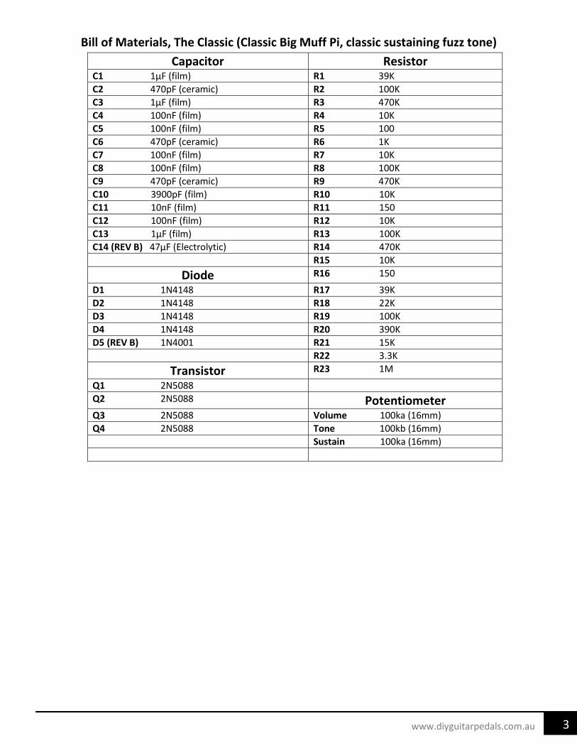
Bill of Materials, Stock Siberian (Russian SovTek style, better bass response) Capacitor Resistor
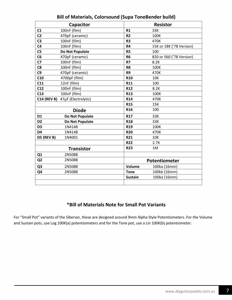
For “Small Pot” variants of the Siberian, these are designed around 9mm Alpha Style Potentiometers. For the Volume and Sustain pots, use Log 100K(a) potentiometers and for the Tone pot, use a Lin 100K(b) potentiometer.
8 www.diyguitarpedals.com.au
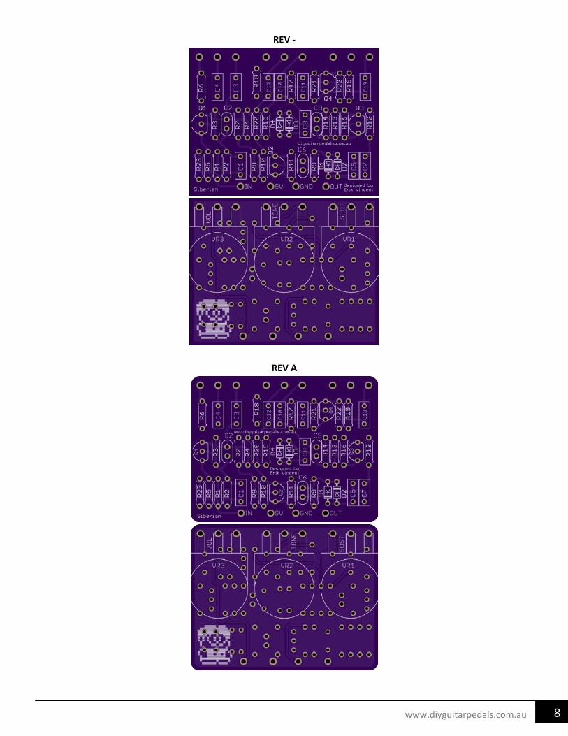
REV -
REV A
9 www.diyguitarpedals.com.au
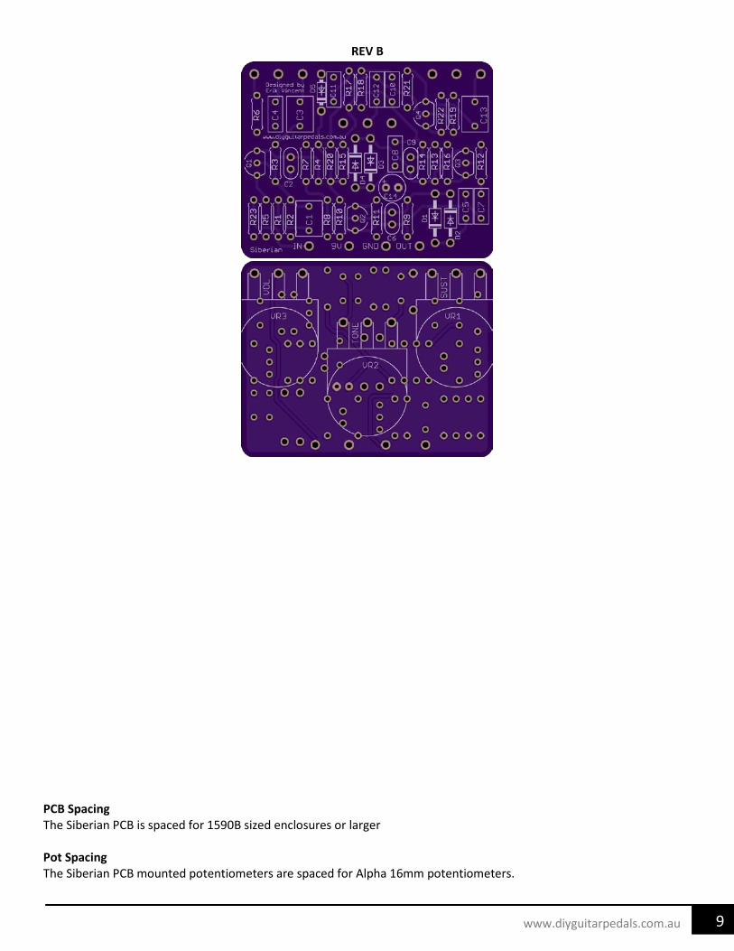
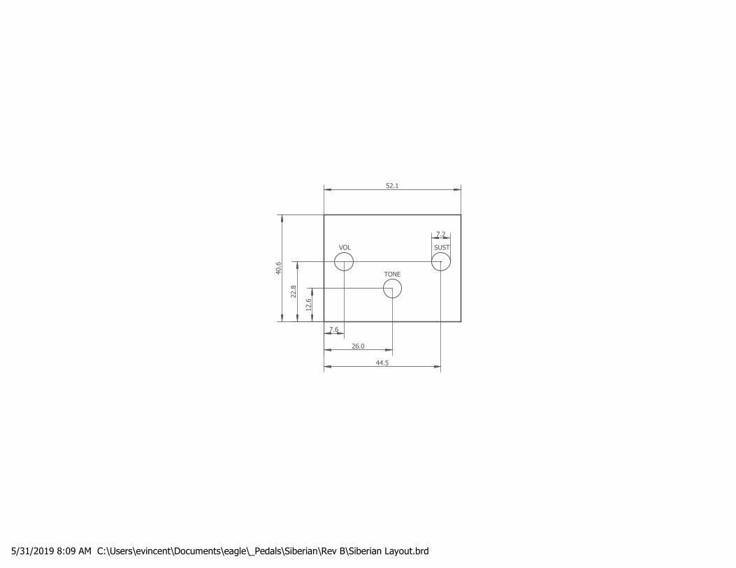
REV B
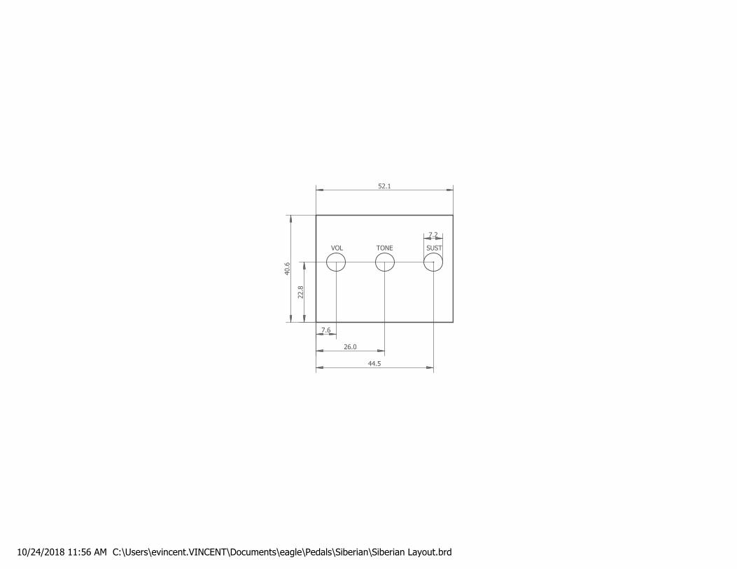
PCB Spacing The Siberian PCB is spaced for 1590B sized enclosures or larger Pot Spacing The Siberian PCB mounted potentiometers are spaced for Alpha 16mm potentiometers.
10 www.diyguitarpedals.com.au
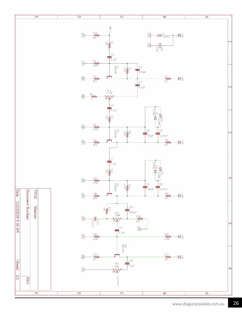
Siberian Circuit Analysis for modifying purposes.
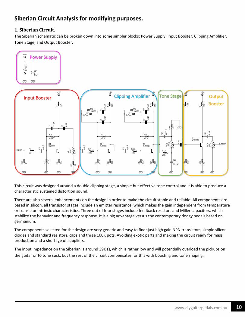
1. Siberian Circuit. The Siberian schematic can be broken down into some simpler blocks: Power Supply, Input Booster, Clipping Amplifier, Tone Stage, and Output Booster.
This circuit was designed around a double clipping stage, a simple but effective tone control and it is able to produce a characteristic sustained distortion sound.
There are also several enhancements on the design in order to make the circuit stable and reliable: All components are based in silicon, all transistor stages include an emitter resistance, which makes the gain independent from temperature or transistor intrinsic characteristics. Three out of four stages include feedback resistors and Miller capacitors, which stabilize the behavior and frequency response. It is a big advantage versus the contemporary dodgy pedals based on germanium.
The components selected for the design are very generic and easy to find: just high gain NPN transistors, simple silicon diodes and standard resistors, caps and three 100K pots. Avoiding exotic parts and making the circuit ready for mass production and a shortage of suppliers.
The input impedance on the Siberian is around 39K Ω, which is rather low and will potentially overload the pickups on the guitar or to tone suck, but the rest of the circuit compensates for this with boosting and tone shaping.
11 www.diyguitarpedals.com.au
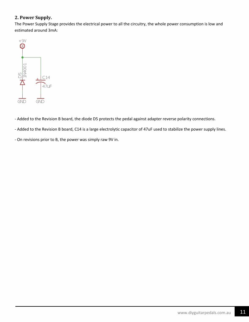
2. Power Supply. The Power Supply Stage provides the electrical power to all the circuitry, the whole power consumption is low and estimated around 3mA:
- Added to the Revision B board, the diode D5 protects the pedal against adapter reverse polarity connections.
- Added to the Revision B board, C14 is a large electrolytic capacitor of 47uF used to stabilize the power supply lines.
- On revisions prior to B, the power was simply raw 9V in.
12 www.diyguitarpedals.com.au
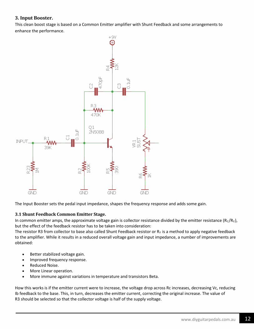
3. Input Booster. This clean boost stage is based on a Common Emitter amplifier with Shunt Feedback and some arrangements to enhance the performance.
The Input Booster sets the pedal input impedance, shapes the frequency response and adds some gain.
3.1 Shunt Feedback Common Emitter Stage. In common emitter amps, the approximate voltage gain is collector resistance divided by the emitter resistance (RC/RE), but the effect of the feedback resistor has to be taken into consideration: The resistor R3 from collector to base also called Shunt Feedback resistor or RF is a method to apply negative feedback to the amplifier. While it results in a reduced overall voltage gain and input impedance, a number of improvements are obtained:
• Better stabilized voltage gain. • Improved frequency response. • Reduced Noise. • More Linear operation. • More immune against variations in temperature and transistors Beta.
How this works is if the emitter current were to increase, the voltage drop across Rc increases, decreasing Vc, reducing Ib feedback to the base. This, in turn, decreases the emitter current, correcting the original increase. The value of R3 should be selected so that the collector voltage is half of the supply voltage.
13 www.diyguitarpedals.com.au
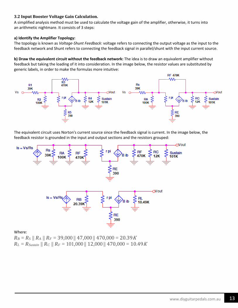
3.2 Input Booster Voltage Gain Calculation. A simplified analysis method must be used to calculate the voltage gain of the amplifier, otherwise, it turns into an arithmetic nightmare. It consists of 3 steps: a) Identify the Amplifier Topology: The topology is known as Voltage-Shunt Feedback: voltage refers to connecting the output voltage as the input to the feedback network and Shunt refers to connecting the feedback signal in parallel/shunt with the input current source. b) Draw the equivalent circuit without the feedback network: The idea is to draw an equivalent amplifier without feedback but taking the loading of it into consideration. In the image below, the resistor values are substituted by generic labels, in order to make the formulas more intuitive:
The equivalent circuit uses Norton's current source since the feedback signal is current. In the image below, the feedback resistor is grounded in the input and output sections and the resistors grouped:
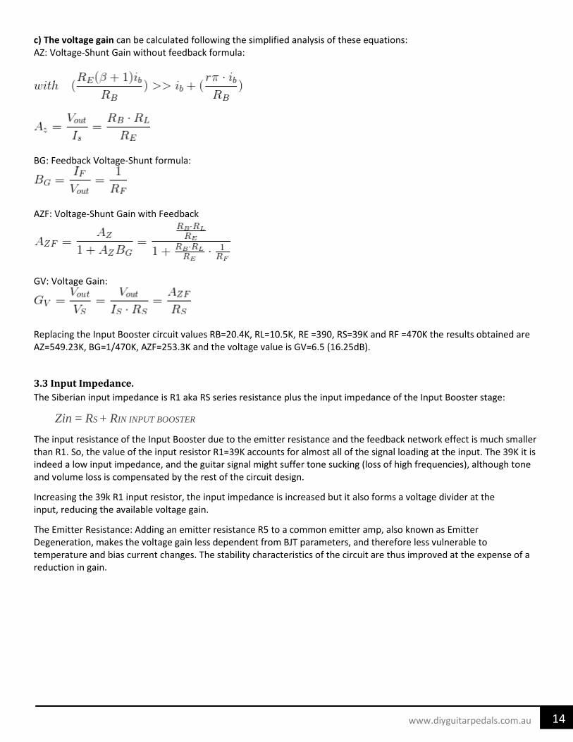
c) The voltage gain can be calculated following the simplified analysis of these equations: AZ: Voltage-Shunt Gain without feedback formula:
BG: Feedback Voltage-Shunt formula:
AZF: Voltage-Shunt Gain with Feedback
GV: Voltage Gain:
Replacing the Input Booster circuit values RB=20.4K, RL=10.5K, RE =390, RS=39K and RF =470K the results obtained are AZ=549.23K, BG=1/470K, AZF=253.3K and the voltage value is GV=6.5 (16.25dB).
3.3 Input Impedance. The Siberian input impedance is R1 aka RS series resistance plus the input impedance of the Input Booster stage:
Zin = RS + RIN INPUT BOOSTER
The input resistance of the Input Booster due to the emitter resistance and the feedback network effect is much smaller than R1. So, the value of the input resistor R1=39K accounts for almost all of the signal loading at the input. The 39K it is indeed a low input impedance, and the guitar signal might suffer tone sucking (loss of high frequencies), although tone and volume loss is compensated by the rest of the circuit design.
Increasing the 39k R1 input resistor, the input impedance is increased but it also forms a voltage divider at the input, reducing the available voltage gain.
The Emitter Resistance: Adding an emitter resistance R5 to a common emitter amp, also known as Emitter Degeneration, makes the voltage gain less dependent from BJT parameters, and therefore less vulnerable to temperature and bias current changes. The stability characteristics of the circuit are thus improved at the expense of a reduction in gain.
15 www.diyguitarpedals.com.au
3.4 Input Booster Frequency Response. The frequency response is tailored by two capacitors: the input decoupling cap C1 which sets the low-frequency response (roll-off the bass) and the Miller Capacitor C2 which shapes the high-frequency response (roll-off the highs):
• Input Capacitor C1: creates a high-pass filter, increasing its value will result in a more bass frequency response and increasing the signal into the pedal. The cut-off frequency is around 19Hz, not disturbing guitar harmonics. Increasing C1 capacitance will allow in more bass while decreasing capacitance will keep out more bass.
• Collector to Base feedback Capacitor: C2 is a Lag Capacitor or Miller Capacitor compensation to avoid oscillation which sets the amplifier bandwidth and the dominant pole frequency. The effective value of the C2 capacitor is increased by the internal collector-base capacitance (base to collector depletion capacitance) of the BJT.
With a C2 of 470pF and depending on the internal BJT capacitance, low pass filter cut-off frequency is around 1.2 kHz. This operation occurs just before the distortion stage; clipping a low-passed signal usually sounds better, smoother and less harsh.
The usual values for this cap are tens to some hundreds of pF, lowering the C2 value will result in a more treble response, rolling-off fewer highs.
16 www.diyguitarpedals.com.au
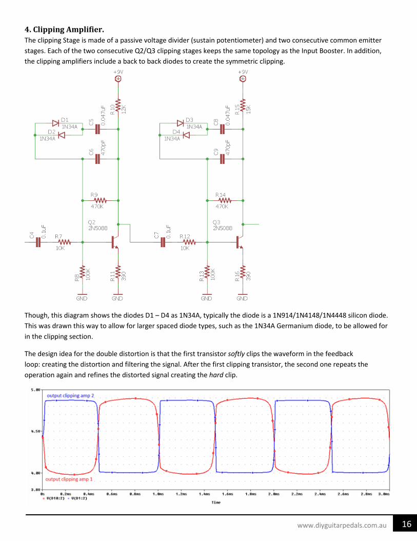
4. Clipping Amplifier. The clipping Stage is made of a passive voltage divider (sustain potentiometer) and two consecutive common emitter stages. Each of the two consecutive Q2/Q3 clipping stages keeps the same topology as the Input Booster. In addition, the clipping amplifiers include a back to back diodes to create the symmetric clipping.
Though, this diagram shows the diodes D1 – D4 as 1N34A, typically the diode is a 1N914/1N4148/1N4448 silicon diode. This was drawn this way to allow for larger spaced diode types, such as the 1N34A Germanium diode, to be allowed for in the clipping section.
The design idea for the double distortion is that the first transistor softly clips the waveform in the feedback loop: creating the distortion and filtering the signal. After the first clipping transistor, the second one repeats the operation again and refines the distorted signal creating the hard clip.
17 www.diyguitarpedals.com.au
4.1 Sustain Circuit. The 100K sustain potentiometer controls the level of the signal going into the clipping blocks. If the level is high, the signal will be more clipped and the distortion effect will hold even if the guitar input signal is not strong. The resistor R6 prevents the signal from coming from the Input Booster from being cut-off when the sustain pot is at the lowest setting. 4.2 Clipping Amplifier Voltage Gain Calculation. The voltage gain can be calculated applying the simplified analysis method as in the Input Booster:
• First Clipping Stage, using the formulas of the Input Booster:
RB = RS||RA||RF = 10K||100K||470K = 8.9K RL = RF||RC = 470K||12K = 11.7K RE = 390 RS = 10K RF = 470K the results obtained are: BG = 1/470K AZ = 267K AZF = 170.3K The Voltage Gain is GV = AZF/RS = 170.3K/10K = 17 (24.6dB). In the real circuit is around 20 dB
• Second Clipping Stage, using the formulas of the Input Booster:
RB = RS||RA||RF = 10K||100K||470K = 8.9K RL = RF||RC = 470K||15K = 14.5K RE = 390 RS = 10K RF = 470K the results obtained are: BG = 1/470K AZ = 330.9K AZF = 194.2K The Voltage Gain is GV = AZF/RS = 194.2K/10K = 19.4 (25.7dB). In the real circuit is around 21 dB
Note: In the calculation, the diodes feedback network is not taken into consideration because it contains big capacitors C5 and C8 which disconnect the path for DC conditions.
The Gain of the second clipping stage is slightly higher (1 or 2 dBs) than the first one. However, the voltage gain of this stage will not reach such values as 24 or 25dBs. As it will be seen in the next point, the gain is limited by the clipping diodes action. The output signal of the amplifiers will never exceed ±0.6V and all the extra gain will modify the slew rate and the shape of the clipped signal.
18 www.diyguitarpedals.com.au
4.3 Clipping Method. The diodes D1-D2 and D3-D4 in the collector-base feedback loop of the transistors, clip the signal when the voltage difference between the input (transistor base) and the output (transistor collector) is higher than the VF of the diode, which is around 0.65V. So they will limit the signal peaks and the output signal will never exceed ± 0.65V.
Diode Voltage Drop Silicon Diodes (1N914, 1N4148, etc) 0.65 V Schottky Diodes (BAT41, 1N5817, etc) 0.3 – 0.4 V Red LEDs 1.2 – 1.4 V Blue LEDs 2.1 V Germanium Diodes (1N34A, 1N270, etc) 0.2 – 0.5 V
The 0.047uF series capacitors C5 and C8 located next to the feedback diodes, allow the AC signal to pass through it and be clipped and block the DC bias voltage. Keeping the transistor operating point undisturbed. These caps determine the frequency band the unit clips. Enlarging this cap will make it clip more bass harmonics, make it smaller for more high-end clipping and archiving more saturated tone, more sustain, and compression. Values between 0.022uF to 1uF are common.
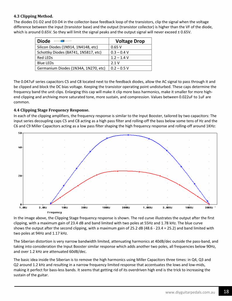
4.4 Clipping Stage Frequency Response. In each of the clipping amplifiers, the frequency response is similar to the Input Booster, tailored by two capacitors: The input series decoupling caps C5 and C8 acting as a high pass filter and rolling-off the bass below some tens of Hz and the C6 and C9 Miller Capacitors acting as a low pass filter shaping the high frequency response and rolling-off around 1KHz:
In the image above, the Clipping Stage frequency response is shown. The red curve illustrates the output after the first clipping, with a maximum gain of 23.4 dB and band limited with two poles at 55Hz and 1.78 kHz. The blue curve shows the output after the second clipping, with a maximum gain of 25.2 dB (48.6 - 23.4 = 25.2) and band limited with two poles at 94Hz and 1.17 kHz.
The Siberian distortion is very narrow bandwidth limited, attenuating harmonics at 40dB/dec outside the pass-band, and taking into consideration the Input Booster similar response which adds another two poles, all frequencies below 90Hz, and over 1.2 kHz are attenuated 60dB/dec.
The basic idea inside the Siberian is to remove the high harmonics using Miller Capacitors three times: in Q4, Q3 and Q2 around 1.2 kHz and resulting in a narrow frequency limited response that accentuates the lows and low-mids, making it perfect for bass-less bands. It seems that getting rid of its overdriven high end is the trick to increasing the sustain of the guitar.
19 www.diyguitarpedals.com.au
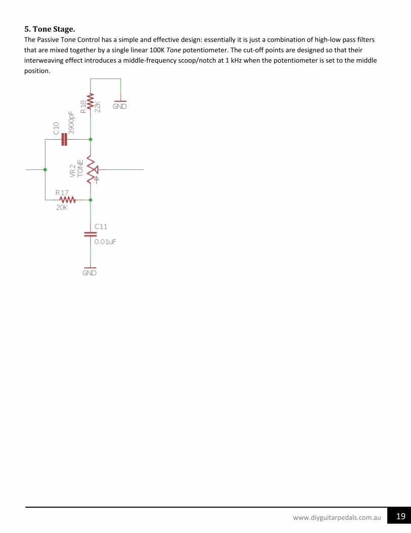
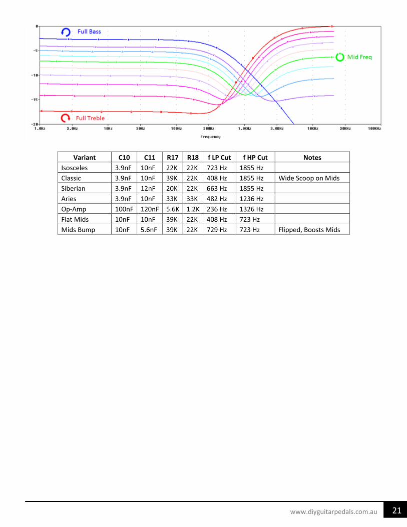
5. Tone Stage. The Passive Tone Control has a simple and effective design: essentially it is just a combination of high-low pass filters that are mixed together by a single linear 100K Tone potentiometer. The cut-off points are designed so that their interweaving effect introduces a middle-frequency scoop/notch at 1 kHz when the potentiometer is set to the middle position.
20 www.diyguitarpedals.com.au
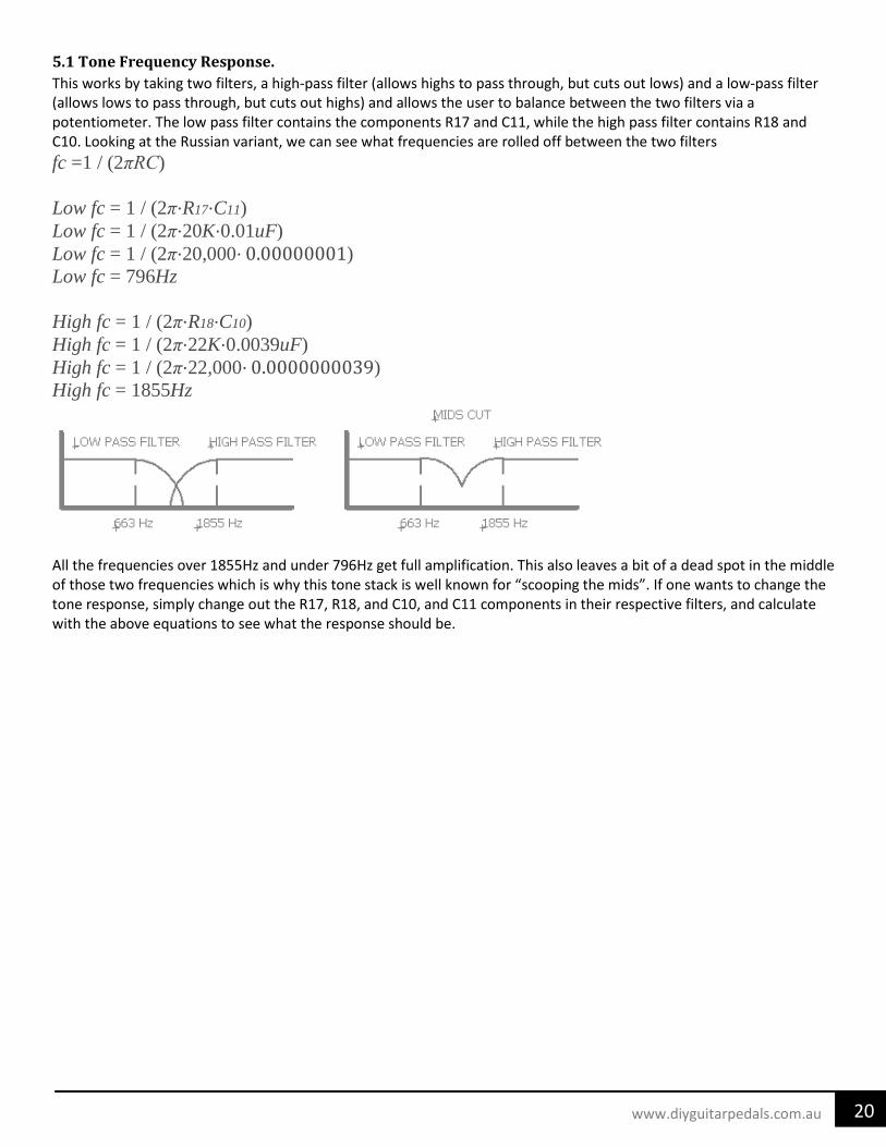
5.1 Tone Frequency Response. This works by taking two filters, a high-pass filter (allows highs to pass through, but cuts out lows) and a low-pass filter (allows lows to pass through, but cuts out highs) and allows the user to balance between the two filters via a potentiometer. The low pass filter contains the components R17 and C11, while the high pass filter contains R18 and C10. Looking at the Russian variant, we can see what frequencies are rolled off between the two filters fc =1 / (2πRC) Low fc = 1 / (2π⋅R17⋅C11)
Low fc = 1 / (2π⋅20K⋅0.01uF) Low fc = 1 / (2π⋅20,000⋅ 0.00000001) Low fc = 796Hz High fc = 1 / (2π⋅R18⋅C10)
High fc = 1 / (2π⋅22K⋅0.0039uF) High fc = 1 / (2π⋅22,000⋅ 0.0000000039) High fc = 1855Hz
All the frequencies over 1855Hz and under 796Hz get full amplification. This also leaves a bit of a dead spot in the middle of those two frequencies which is why this tone stack is well known for “scooping the mids”. If one wants to change the tone response, simply change out the R17, R18, and C10, and C11 components in their respective filters, and calculate with the above equations to see what the response should be.
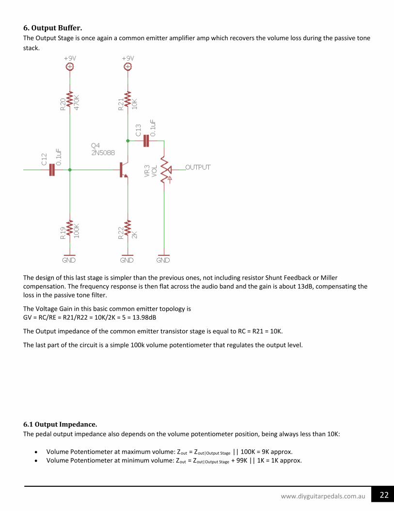
6. Output Buffer. The Output Stage is once again a common emitter amplifier amp which recovers the volume loss during the passive tone stack.
The design of this last stage is simpler than the previous ones, not including resistor Shunt Feedback or Miller compensation. The frequency response is then flat across the audio band and the gain is about 13dB, compensating the loss in the passive tone filter.
The Voltage Gain in this basic common emitter topology is GV = RC/RE = R21/R22 = 10K/2K = 5 = 13.98dB
The Output impedance of the common emitter transistor stage is equal to RC = R21 = 10K.
The last part of the circuit is a simple 100k volume potentiometer that regulates the output level.
6.1 Output Impedance. The pedal output impedance also depends on the volume potentiometer position, being always less than 10K:
7. Modifications Following is a couple of worthwhile modifications that can be applied to the Siberian. 7.1 Capacitors C1, C3, and C13 are used for frequency filtering. Using higher value capacitors here will reduce bass response and help with the mid-range frequencies better. Typical ranges are 10nF (Civil War Muff) to 10uF (Ram’s Head Muff). C2 is part of the low pass filter, which cuts out high frequencies. This operation occurs just before the distortion stage; clipping a low-passed signal usually sounds better, smoother and less harsh. The usual values for this cap are 47pF to 680pF, lowering the value will result in a more treble response, rolling-off fewer highs. C5 and C8 located next to the feedback diodes, allow the AC signal to pass through it and be clipped and block the DC bias voltage, keeping the transistor operating point undisturbed. These caps determine the frequency band the unit clips. Enlarging this cap will make it clip more bass harmonics, while making it smaller will make it clip more high-end and keep more saturated tone, more sustain, and compression. 7.2 Resistors The input resistance of the Input Booster due to the emitter resistance and the feedback network effect is much smaller than R1. So, the value of the input resistor R1 accounts for most of the signal loading at the input. With R1 having a low input impedance (10’s of Kilo-ohms, typically), and the guitar signal might suffer tone sucking (loss of high frequencies), although tone and volume loss is compensated by the rest of the circuit design. Increasing R1 beyond 39K, the input impedance is increased but it also forms a voltage divider at the input, reducing the available voltage gain. 7.3 Transistors Currently this pedal uses four 2N5088 NPN Transistors, which have a rather high gain to them. Changing out to different transistors with higher or lower gain, may be desired. For lower gain, a 2N3904 would be an alternative, whereas a 2N5089 would give it a bit higher gain. For a wide swinging transistor, a SS9014 would also be an alternative. Q1 is just an emitter follower transistor for the input boost of the circuit. Q2 and Q3 work similar as Q1, but are part of the clipping stage of the circuit. Q4, similarly works like the others, but is part of the output boost circuit. 7.4 Diodes On some fuzzes, it is desired to remove the first set of diodes in the first clipping stage, D1 and D2. This was a method that Colorsound used on their Big Muff Pi clones. This made it sound more like a silicon ToneBender than a BMP. Changing out diodes for different clipping options, due to different forward voltages and voltage drops will also change the sound. Some modern, boutique clones have swapped out the silicon diodes in favor of red LEDs because of their forward voltage being double that of a standard silicon diode. Blue LEDs are even more extreme on their clipping due to a nearly 4x the forward voltages. For a softer-knee clipping, Germanium diodes, such as the 1N34A could be installed with some having half or even a third the forward voltage of a standard silicon diode. Schottky Diodes are somewhere in the middle between Germanium and standard Silicon diodes.
24 www.diyguitarpedals.com.au
25 www.diyguitarpedals.com.au
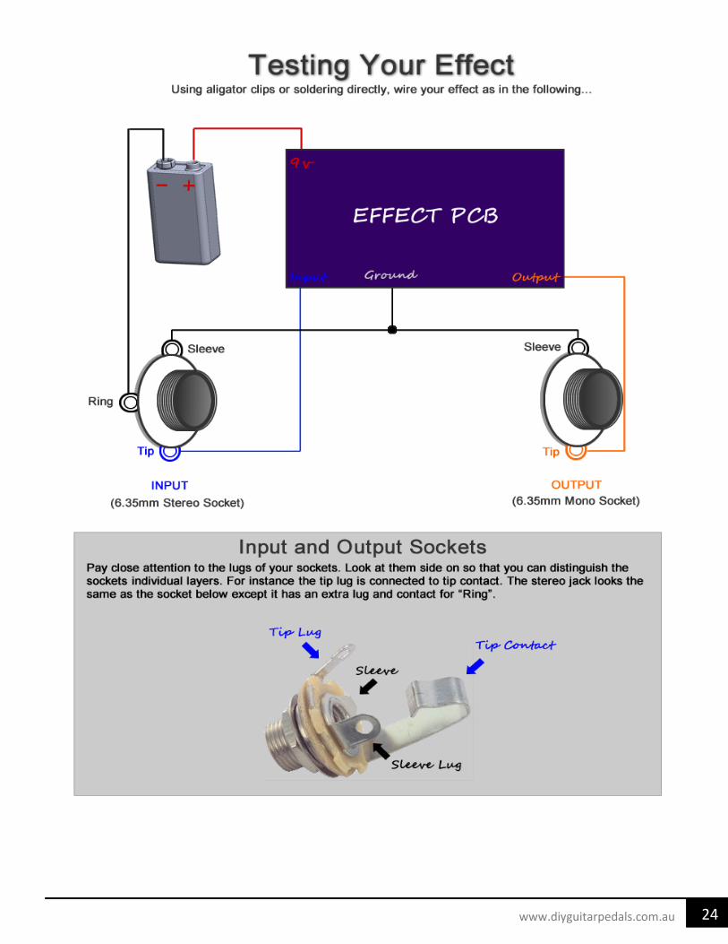
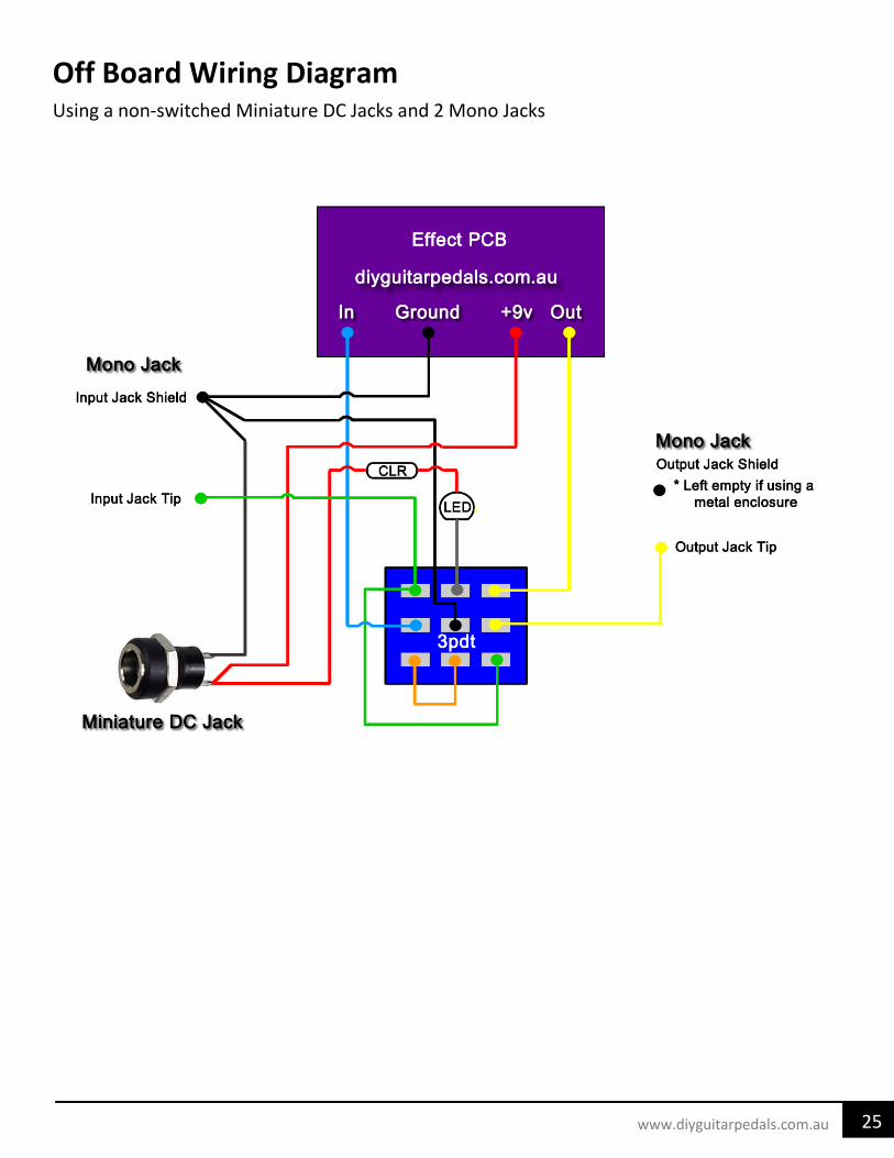
Off Board Wiring Diagram Using a non-switched Miniature DC Jacks and 2 Mono Jacks
26 www.diyguitarpedals.com.au
10/24/2018 11:56 AM C:\Users\evincent.VINCENT\Documents\eagle\Pedals\Siberian\Siberian Layout.brd
VOL TONE SUST
40.6
52.1
7.2
22.8
7.6
26.0
44.5
10/24/2018 11:56 AM C:\Users\evincent.VINCENT\Documents\eagle\Pedals\Siberian\Siberian Layout.brd
VOL TONE SUST
40.6
52.1
7.2
22.8
7.6
26.0
44.5
5/31/2019 8:09 AM C:\Users\evincent\Documents\eagle\_Pedals\Siberian\Rev B\Siberian Layout.brd