NASA-CR-200029 NASA/WVU Software IV & V Facility Software Research Laboratory Technical Report Series NASA-IVV-95-012 WVU-SRL-95-012 WVU-SCS-TR-95-32 CERC-TR-TM-95-007 The Specification-based Validation of Reliable Multicast Protocol by Yunqing Wu I (NASA-CR-200029) THE SPECIFICATION-BASED VALIDATION OF RELIABLE MULTICAST PROTOCOL: PROBLEM REPORT M.S. Thesis (West Vi rqinia Uni v.) 64 p Unclas G3/61 0098261 National Aeronautics and Space Administration West Virginia University https://ntrs.nasa.gov/search.jsp?R=19960011369 2018-06-21T08:35:16+00:00Z
Transcript
NASA-CR-200029
NASA/WVU Software IV & V FacilitySoftware Research LaboratoryTechnical Report Series
NASA-IVV-95-012WVU-SRL-95-012
WVU-SCS-TR-95-32CERC-TR-TM-95-007
The Specification-based Validation of Reliable MulticastProtocol
by Yunqing Wu
I
(NASA-CR-200029) THESPECIFICATION-BASED VALIDATION OFRELIABLE MULTICAST PROTOCOL:PROBLEM REPORT M.S. Thesis (WestVi rqinia Uni v.) 64 p
Chapter 3 Validation Strategy and Process Model 113.1 Introduction to protocol verification 113.2 Validation Methods and Our Early Experience 133.3 Theorem Prover 143.4 Model Checkers 17
3.4.1 SMV 173.4.2 Murphi 183.4.3 SPIN tool 20
3.5 Our Verification Strategy and Process Model 21
Chapter 4 Formal Models of RMP 254.1 Single-Site Murphi Model 25
4.1.1 Some Simplifications 254.1.2 Minimal State Variables 274.1.3 State Transition Rules and Actions 284.1.4 Deadlock Avoidance 294.1.5 Verification Analysis and State Invariants 324.1.6 Example Problems Found 34
4.2 Multiple-Site SPIN Model 374.2.1 The Need for Multiple-Site Model 374.2.2 Some Simplifications 384.2.3 Results 404.2.4 Future Directions 43
Chapters Test Generation 455.1 Conformance Testing and Testing Strategy 455.2 Test generation 465.3 Discussion 48
Chapter 6 Conclusion 49Bibliography 50Appendix 52
Introduction
Chapter 1 Introduction
Many software engineering papers that discuss software quality begin with a phrase like
"Software is always delivered late, over budget and full of errors." [GANN94] As software
becomes more sophisticated and complex, the task of producing correct, reliable and high-
standard software remains difficult. As computers become cheaper, smaller, and more
powerful, they become more pervasively spread out in modern society and play more
important roles in every aspect of our lives. Since nowadays, most computers are
interconnected by a network, a failure of software has far more reaching effect. It is clear
that the need for building correct software systems become more demanding.
Formal verification and validation are effective ways to improve the software quality.
However, the software industry is still reluctant to accept formal methods. Formal methods
are perceived as impractical and not cost-effective. The reasons for this perception could
be many-fold, but one obvious shortcoming of current practices is the separation of formal
verification and the implementation activities in most software development processes.
The formal methods are employed to check the logical consistency and completeness of
designs and specifications, but this use has not been integrated into the entire life-cycle of
software development. Formal models of a design are often developed and then abandoned
in the later phases of development. When change occurs, we have to modify the code and
the formal models independently. This not only increases the cost of development, but also
deepen people's impressions about the limits of formal methods.
Introduction
In this report, we propose a new software development process that integrates formal
methods into the entire life cycle of the software development In the requirement and
design phases, formal methods serve to model changes of software designs before the
implementation and provide checks for completeness and consistency. During the coding,
however, formal models can be refined along with the implementation of the specifications.
For instance, pragmatic issue such as performance may require design decisions to be
reconsidered. Any problem detected by formal models are fedback to designer and changes
are reflected in the specifications. In parallel, implementation can be modified at the early
stage. In the later life cycle, the same formal models can be used to generate a test suite for
functional testing of the implementation. Using this approach, we can achieve high fidelity
between the specifications, formal models, and the implementation. We have applied this
process in the development of a complex internet protocol, and our experience suggests that
this process helped us to improve the quality of our software. In our case, we used existing
automated verification tools to validate the design of the protocol. During the
implementation, we manipulate the models in order to analyze the protocol with respect to
the desired properties. This analysis leads to discovery of some minor specification errors.
In the later phases, we used the same formal models to generate a test suite for conformance
testing of the protocol independently.
In Chapter 2, we introduce the reliable multicast protocol and describe the method for
specifying the protocol operations, hi Chapter 3, we review existing verification tools and
outline our validation strategies based on these tools. We present our Reliable Multicast
Protocol (RMP) formal models in Chapter 4. These formal models are based on different
level of abstraction and are developed for different verification tools. They serve to verify
different aspects of the specifications by using different levels of abstraction. In Chapter 5,
we discuss test generation using the formal models. We conclude with a short discussion
in Chapter 6.
Reliable Multicast Protocol
Chapter 2 Reliable Multicast Protocol
2.1 Introduction to RMP
Multicasting is a technique for passing copies of a single packet to a subnet of all possible
destinations. The Reliable Multicast Protocol (RMP) is a communication protocol that
provides a totally ordered, reliable, atomic multicast service on top of an unreliable IP
multicast service. RMP is based on the set of reliable broadcast protocols presented by J.
M. Chang and N. F. Maxemchuk [CHAN84]. RMP is designed to be a transport level
protocol that provides reliable datagram delivery on top of a unicast or multicast unreliable
datagram service. The main goal is to provide high throughput for totally ordered messages
with low latency. It provides a transport mechanism by which a user can design and
implement fully distributed, fault-tolerant applications without the need to deal with the
lower level primitives of communication. Since RMP is aimed at providing a transport
level service, performance is a high priority. RMP provides the following features
[MONT94]:
• High throughput for totally ordered messages with low latency
• Virtual Synchrony
• Support of process group models
• Efficient changes to the process group
• Scalability of process groups
• Rexibility of choice for resiliency and fault-tolerance level
Reliable Multicast Protocol
Here, by virtual synchrony, we mean that all sites will receive the same set of messages
before and after a group membership change. In this way, a distributed application can
execute as if its communication was synchronous, when it is actually asynchronous. Our
RMP implementation shows excellent scalability: its single data sender throughput stays
roughly constant as the number of destinations increases. RMP also offers different quality
of services (QoS) levels: from unreliable, totally ordered, majority resilient to totally
resilient
2.2 RMP operations
RMP is operated in two distinct modes: a normal operation mode and a recovery mode. In
the normal operation mode, RMP handles delivery of the data packets, token passing of the
token, acknowledgment of data packets and membership changes. The protocol provides
its primary services in the normal operation mode. The protocol switches from the normal
operation mode into the recovery mode whenever a site detects a failure and tries to recover
from the failure. After the new ring has been successfully reformed and synchronized to the
same point, the protocol transits into the normal operation mode once again.
To illustrate the RMP operations, let us see a simple example. Supposed that a RMP token
ring has been formed with three members: A, B and C. Suppose, the site B is the current
token site. Assume that Site A sends a message with sequence number 1 and that almost
simultaneously site C sends a message with sequence number 1 as well. Site B sees the
message from site A just before the message from site C and therefore orders the two
message by sending an ACK, ACK((A,1), (C,l), C,l). The ACK will be placed in the
imposed order with a timestamp of 1. The data messages will also be placed in the order
with timestamps of 2 and 3. These timestamps are implied because of the order they arc
placed in within the ACK. The new token site is C. If site C does not see any more data
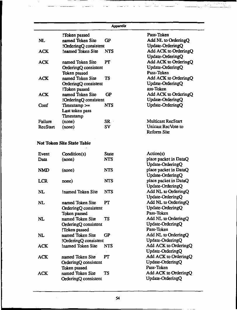
specification describes the transition and corresponding actions for a site in any of the 12
states under the 18 different events. Typically, a site's actions include placing the data
packet in the Data Queue, adding ACK packets in the Ordering Queue, updating the
Ordering Queue, passing the token and multicasting or unicasting certain packets. Here
ReOable Multicast Protocol
updating the Ordering Queue implies identifying the corresponding data packets from the
Data Queue and sending out NACK packets for missing data packets. Another important
action is passing the token. It is taken whenever a site is named as a token site and its
ordering queue is consistent. If the token can be successfully passed, an ACK will be
generated and Multicast to all members. Correspondingly, the token is passed to next site.
A positive acknowledgment policy governs the sending of some packets: the source site
will keep on retransmitting the packet until certain condition occurs. The details of this
policy can be found in the RMP specifications.
Table 1: RMP Normal Operation Specificationsf*
pnrratf"<M^M v V* ""''f&1ll*&;' -
NTS
NTS
NTS
NTS
Mvmtff •.
ACK
ACK
ACK
ACK
Cuurrent'"'""'ClliaitiW5 '"
Not NamedTS
NamedTSOrderQ ConsistentToken Passed
NamedTSOrderQ ConsistentToken Not Passed
NamedTSOrderQ Inconsistent
Btesl'$&&"
PT
TS
NTS
PT
i';;-;'"'̂ ' ; '̂'j^^f^^J^^^&**ff ^ fS fff f s *•*•£ ff f -y f &S^fffi$iiiiwsSv§A
Add ACK in OrderQUpdate OrderQ
Add ACK in OrderQUpdate OrderQPassToken
Add ACK in OrderQUpdate OrderQPassToken
Add ACK to OrderQUpdate OrderQ
Table 1 shows a part of mode table for the protocol operations. The site is in the NTS (Not
Token Site) state under the ACK event (the receipt of Acknowledgment packet). If an ACK
event occurs and the site is not named as the next token site, the site will simply put ACK
packet into Ordering Queue, update the Ordering Queue and stays in NTS state. If ACK
Reliable Multicast Protocol
packet names the current site as the next token site, the current site will first put the packet
in the Ordering Queue, update the Ordering Queue, and try to pass the token to the next site.
If the token is successfully passed and the Ordering Queue is consistent up to the current
time stamp, the site transits to PT (Passing Tokensite) state. If the Ordering Queue is
consistent and the token has not been passed, it transits into TS (Token Site) state. Finally,
if the site is named as the next token site by the ACK packet and the Ordering Queue is not
consistent up to the current time stamp, it transits into GP (Getting Packets) state to wait
for more packets to fill up the missing slots.
10
Validation Strategy and Process Model
Chapter 3 Validation Strategy and Process Model
3.1 Introduction to protocol verification
A well-structured protocol design should follow two common themes: simplicity and
modularity. Simplicity means that the protocol can be built using a small number of well-
designed and well-understood pieces. Modularity means that a complex function can be
built from smaller pieces that interact in a well-defined and simple fashion. Each smaller
piece is a light-weight protocol that can be separately developed, verified, implemented,
and maintained. Generally, a well-formed protocol should have the following
characteristics [HOLZ91]:
• not over-specified: it does not contain any unreachable or inexecutable code;
• not under-specified: it may not cause unspecified receptions during its execu-
tion;
• bounded: it can not overflow known system limits;
• self-stabilizing: if a transient error arbitrarily changes the protocol state, a self-
stabilizing protocol always returns to a desirable state within a finite number of
transitions, and resume normal operations;
• self-adapting: it can adapt, for instance, the rate at which data are sent to the rate
at which the data links can transfer them, and to the rate at which the receiver can
consume them;
• robust: it must be prepared to deal appropriately with every feasible action and
with every possible sequence of actions under all possible conditions. The protocol
11
Validation Strategy and Process Model
should make only minimal assumptions about its environment to avoid dependen-
cies on particular features that could change;
• consistent: three consistency standards include: deadlock-free — no states in
which no further protocol execution is possible; livelock-free— infinite looping
without ever making effective progress; improper terminations — the completion
of a protocol execution without satisfying the proper termination condition.
Since RMP is a complicated protocol, the validation of the protocol design is important to
increase confidence in its reliability and safety during operation. To verify that RMP
specifications have all of the above characteristics is difficult and may even be impossible.
The design of RMP includes many features that directly relate to the above requirements.
Many of these features are borrowed from the experience in implementing TCP. For
example, the recovery mode is designed to satisfy the requirement of self-stabilization.
RMP time-out and retransmission mechanism applies self-adapting techniques. Since our
concentration is on the RMP operation specifications, the main emphasis of our validation
is on the completeness and consistency of RMP specifications, i.e. proving that the protocol
is well-specified and consistent.
Before we get into the details of our formal analysis, it is necessary for us to clarify the
meaning of verification and validation. The conventional meaning of these two words are
best described by:
Verification: Are we building the product right?
Validation: Are we building the right product?
In other words, the verification is generally referred to the activities of certifying that a
product meets its specifications, whereas the validation is referred to confirming that the
product satisfies the original user requirement. But in the literature, these two words are
12
Validation Strategy and Process Model
often used interchangeable. For example, for all model checkers we have used, most of
them use verification to describe the formal analysis activities, but one tool uses validation
exclusively for data communication protocols [HOLZ91]. Actually these tools are
basically performing the same activities. Since in this report, we have used several different
tools to perform our formal analysis, and different tools have different convention in using
these two words, we do not make specific distinction for them. The overall goal of this
report is to validate the formal specifications of RMP, i.e. to prove if the specifications
possess the desired properties. To achieve this goal, we use some automated verification or
validation tools. So in the context of specific tool, we will follow the convention of the tool
to use verification or validation. In the end, we use the formal models to generate a test suite
for implementation conform ance testing. This testing is strictly a verification activity.
3.2 Validation Methods and Our Early Experience
The current practice of protocol validation can be dividend into two types: mathematical
proofs and model checkers. The mathematical proof approach involves specifying the
protocol assumptions as axioms and proving the protocol properties as a sequence of
lemmas and theorems. It may be a pure mathematical proof or the proof based on the use
of some theorem provers. Another approach is based on the use of model checkers. In this
case, protocol operations are specified in the model checker's formal specification
languages and used as a input to the verification systems. Verifiers then perform an
exhaustive search over all possible state spaces according to the specified protocol
operations. The protocol properties are verified against all possible states and paths.
Currently there are several theorem provers and model checkers available for free. The
advantages of the mathematical proof approaches include its rigorous, precise derivation of
protocol properties, and independence of lower-level implementation. The main
disadvantages of mathematical approaches includes the high-level abstraction that is
13
Validation Strategy and Process Model
separated from the implementation. The lack of traceability between the theorems and
implementation makes it very difficult to find direct correspondence between them. For the
model checkers, it is more straight forward to translate the protocol operations into the
system-specific specification language and the proven properties can be directly related the
design specification and implementation.
In our first attempt to formally verify the RMP, we used the SMV model checker
[BURC90]. Some initial attempts reveal some limits on this model checker, including the
state explosion problem and the lack of high level data-structure support We then decided
to use the PVS [RUSH93]. There is a rigorous mathematical proof of the Token Ring
Protocol [CHAN84], on which RMP is loosely based. We then switched our concentration
on the theorem prover approach and tried to replicate the theorem proof by PVS. Because
PVS is a mechanized system, most proof steps must be input by the interactive user. We
didn't pursue along this approach too far, since it is not tractable to implementation. It is
until we found other two model checkers, i.e. Murphi and SPIN, we made some solid
progress in constructing the formal models of RMP. Through this early trial-and-error
approach, we learned that it is very important to construct the formal models at an
appropriate abstract level compatible to the underlying tool's specification language. In the
following sections, we describe the properties of these tools and our experience with them.
We feel that these experiences are very important for directing us to our current success.
Finally we outline our verification strategy and the development process model based on
these available tools.
3.3 Theorem Prover
The mathematical proof approach for formal protocol verification involves specifying the
protocol assumptions as axioms and proving the protocol properties as a sequence of
lemmas and theorems. It may be a pure mathematical proof such as the verification of the
14
Validation Strategy and Process Model
Token Ring Protocol [YODA92] or the proof based on the use of some theorem provers
[DREX92]. A typical and popular theorem prover system we have come across and used
in our project is PVS — Prototype Verification System from Computer Science Laboratory,
SRI International, Stanford University. It is a prototype for a system specification and
verification based on higher-order logic. It consists of a specification language integrated
with support tools and a theorem prover. PVS tries to provide the mechanization needed to
apply formal methods both rigorously and productively. The primary purpose of PVS is to
provide formal support for conceptualizing and debugging in the early stages of the life-
styles of the design of a hardware or software system, when the executable version of the
system is still not available. PVS has the following features [RUSH93]:
• Early Stage Verification: It is intended to be useful for early life-style applica-
tion of formal methods, instead of program verification of a program in some con-
crete programming language satisfied the specification. It is designed to help in
detection of design errors as well as in the confirmation of "correctness";
• Rich Type System: Compared with some similar systems, it has very rich type-
system and correspondingly rigorous typechecking. A great deal of specification
can be embedded in PVS types, and typechecking can generate proof obligations
that amount to a very strong consistency check on some aspects of the specifica-
tion. It combines a rich expressive specification language and an effective theorem
prover,
• Interactive Proof and Automation: PVS provides a good combination of direct
control by the user for the higher levels of proof development, and the powerful
automation for the lower proofs. It proves the theorem through the process of chal-
lenging specifications. At the high level proof, user can easily input the prove com-
mands, while most lower proofs can be carried out by the powerful theorem
prover,
• Good Conservative Extension: It helps eliminate certain kinds of errors by pro-
15
Validation Strategy and Process Model
viding very rich mechanism for conservative extension. PVS provides both the
freedom of axiomatic specification, and the safety of a generous collection of defi-
nitional and constructive forms, so that users may choose the style of specification
most appropriate to their problems.
PVS has been used to verify several systems, including fault-tolerating protocol, airline-
reservation system, selected aspects of the control software for NASA's space shuttle
project. It runs on workstation with mediate system resources requirement of disk space
and memory space(30 MB hard disk + 20MB swapping space, > 12 MB memory). PVS is
implemented in Common Lisp. All versions of PVS require Gnu Emacs as its user
interface. Latex and appropriate viewer are needed to support certain optional feature of
PVS, such as the pretty typing of the proof.
RMP is based on Chang's Token Ring Protocol and there is a mathematical proof on the
protocol based on the use of the modal primitive recursive functions [YODA92]. Our first
effort was to replicate the proof by using Paves since, time operators and sequence and
behavior types [RUSH93]. These constructed types can be used directly to specify RMP
properties. We made some progress in replicating the proof, yet we didn't pursue our
verification of the protocol design using PVS. First, the learning curve of PVS is very steep
and PVS proof are still mostly mechanic. Even the proof of some simple theorems can be
quite involved and requires a lot user interactive input Secondly, we feel that even if we
can formally prove some theorems with the protocol, it is difficult to relate the theorems
with the actual implementation. Since mathematical theorems proved by PVS are generally
at the very high abstract level and there is still significant gap between the implementation
and the theorems. As our primary goal was to integrate formal methods into the software
development process and to increase the quality and reliability of the software, we chose to
pursue our verification based on analysis by model checkers whose state-based analysis can
16
Validation Strategy and Process Model
more easily be compare with tests executed on the implementation. A recent report shows
a new implementation of theorem prover which has integrated the model checkers into the
prover system to allow more powerful automatic proof through model checker [RAJA95].
This new system may help to relieve heavy user interaction and lead to shorter proofs.
3.4 Model Checkers
Model checkers use a high-level formal specification as language input and generate code
to perform an exhaustive search over all possible states in order to verify properties of the
specified system. In an effort to facilitate the automatic verification of high-level design for
hardware and software systems, several tools have been developed and used in many
applications. We used three tools in the process of verifying RMP: SMV-Symbolic Model
Verifier from Carnegie-Mellon University [BURC90]; MURPHI from Stanford University
[MELT93] and SPIN from AT&T Bell Laboratories [HOLZ91, HOLZ94]. These tools
have their own features and users can choose appropriate tool to perform different
verification tasks at different levels. In the following subsections, we describe these three
tools and our experience with them.
3.4.1 SMV
SMV is a tool for checking finite state systems, from completely synchronous to
completely asynchronous, against the system specification expressed in the temporal logic
CTL [BURC90], It allows for specifications of non-determinism and concurrency in its
model. SMV attempts to directly model system behavior by specifying state transitions
explicitly for each state variable, expressed as procedures of variable assignments. SMV
has been effectively used in some hardware design verification. It supports rich temporal
logic specifications and an incremental, modular approach to protocol specification and
verification.
17
Validation Strategy and Process Model
We have constructed several simple formal RMP models using SMV. Since our first
attempt involved too much protocol implementation details, we faced severe difficulties in
extending the simple models to include the full protocol specifications. In addition, when
the model is incrementally built, we quickly run into the problem of state explosion. There
is simply no enough memory to perform exhaustive state space search and extending the
running time does not help. One execution of a SMV mode of RMP was aborted after about
ten days.
3.4.2 Murphi
The Murphi Verification System consists of the Murphi compiler and the Murphi
description language. The Murphi Compiler generates a special purpose verifier in C++
from a Murphi description. After further compiling by C++ compiler, the special purpose
verifier can be used to check the properties of the system, such as error assertion, invariant
and deadlock. The Murphi description language is a high-level description language for
finite-state asynchronous concurrent systems. It supports user-defined data types,
procedures, and parameterization of descriptions. A complete Murphi description consists
of declaration of constants, types, global variables, and procedures; a collection of
transition rules; a description of the initial states; and a set of invariants.
In Murphi, a state is an assignment of values to all of the global variables of the description.
The verifier starts execution in the specified start state. It then applies all executable rules
to this state to generate new states. All visited states and unexplored new states are stored
in two state queues. Whenever a next state is generated by applying a rule to a unexplored
state, it is compared with all visited states to see if it a new state. The execution stops if an
error occurs or if all executable rules have been applied to all states and no new state can
be generated.
18
Validation Strategy and Process Model
Because Murphi choose the next executable rule arbitrarily from all applicable rules, the
Murphi descriptions are non-deterministic. So the correct Murphi program must do the
right thing no matter which rules are chosen. This execution model is good for describing
asynchronous systems where different processes run at arbitrary speed which interact via
shared variables. Message passing can be modelled by reading from and writing to a buffer
variable or array.
The Murphi verification system can be run in two different modes: simulator mode or
verifier mode. In the simulator mode, the simulator chooses among the rules arbitrarily to
get the next state. It will run forever or until an error occurs. On the other hand, the verifier
considers the results for ALL possible choice either by breadth-first search or depth-first
search procedures. It stores all states in a large hash tables so that it can cut off the search
whenever it encounters a state it has seen before. Explicit "assert" and "error" statements
in the Murphi model description can be checked in each step. If one of these conditions
occurs, the verifier halts and print a diagnostic consisting of a reconstructed sequence of
states that leads from the initial state to the error state. All invariants expressions are
checked along all explored paths. Initially, Murphi was designed for hardware design
verification. It has been successfully used to verify some hardware design as well as some
protocol design, including the design of large cache-coherence protocol (DASH)
[LENO92].
Our first trial on Murphi has the same problem as we had on SMV. The reason is that we
tried to construct a model which involves too much detailed on the protocol operations.
When we tried to extend out simple model, we faced the same state explosion problem.
Only after we decided to construct our model at a much higher level did we start to get some
real progress in the Murphi model. Our later experience shows that Murphi is a good
verification tool at this level, because it offers the following characteristics:
19
Validation Strategy and Process Model
• Asynchronous State-Machine: Murphi is designed for the verification of asyn-
chronous state-machine;
• One-to-One Rule Translation: Our protocol specifications can be easily transfer
into Murphi rule specification, which help us to keep high fidelity between our
models and the protocol specifications;
• Invariant and Assertion: Murphi verification system has rich supports for tem-
poral logic invariant specification and insertions of assertion in the specification. It
also support fairness properties specification along the exploration path.
These characteristics are very helpful to our protocol verification. Therefore, we have
performed most of our verification analysis based on our Murphi models of RMP.
3.4.3 SPIN tool
SPIN is a tool for analyzing the logical consistency and general verification for proving
correctness properties of distributed or concurrent systems, especially for data
communication protocols. The system is described in a modeling language called
PROMELA. The language allows for the dynamic creation of concurrent processes.
Communication via message channels can be defined to be synchronous (i.e. rendez-vous),
or asynchronous (i.e. buffered). The protocol system is described as a group of processes
running at their own rate, exchanging message through communication channels. Each
process can make state transition based on the state variable values and the channel event
and produce output to other processes' communication channels.
Given a model system specified in PROMELA, SPIN can either perform random
simulations of the systems's execution or it can generate a C program that performs a fast
exhaustive validation of the system state space. During simulations and validations, SPIN
checks for the absence of deadlocks, unspecified receptions, and inexecutable code. The
20
Validation Strategy and Process Model
validator can also be used to verify the correctness of system invariants specified as never
clauses, and it can find non-progress execution cycles.
Compared with the Murphi tool, SPIN has several additional advantages. First, SPIN is
especially designed for verification of data communication protocols, and it currently has
over 1000 active users in both academic and industrial world. Secondly, it has the explicit
support for the communication channels between processes, which is good for instantiating
the detailed communication mechanism between RMP processes. Thirdly, SPIN has
adopted some advanced algorithms to address the state explosion problem. Users can use
either state reduction algorithm or bit-state reduction to perform best possible search in the
case of state explosion. After we successfully constructed an abstract formal model using
Murphi, we switched to SPIN to include the detailed communication mechanisms among
different processes and verify the protocol at lower level of details than the Murphi model.
3.5 Our Verification Strategy and Process Model
From the above review, we can conclude that theorem provers usually work on a higher
level of abstraction than the model checkers. From PVS, Murphi, to SPIN, they can
simulate protocol operation details in a increased order. In our RMP development project,
our main goal is to increase the quality and reliability of the RMP implementation. As there
is already rigorous mathematical proof of the basic token ring algorithm, it is more
appropriate for us to use model checkers to verify the completeness and consistency of the
protocol specifications. At this point, it is very critical to choose appropriate level of
abstraction to be simulated by the model checkers. Our early trials on these tools gave us
valuable experience in choosing a suitable abstraction level. Our initial attempts on all of
these tools involved too much operation details, perhaps influenced by the RMP
implementation. Only after we determined to use a higher-level abstraction to specify and
simulate the RMP operations, we started to make some real progress in constructing formal
21
Validation Strategy and Process Model
models. While SMV does not support complex data structure, our first model involved
some lower level simulation of the protocol operations, which make it hard to build a
complete model. After that, we decided to use the Murphi tool to build a more abstract
formal model of RMP. At this level, we do not concern about the details of the underlying
data structures. Instead we used non-deterministic algorithms to allow for all possible
transitions. In this way, we built our first Murphi model of RMP. Based on the success of
the first model, we further construct more elaborated interaction model involving lower
level data structures using SPIN'S communication channels.
In summary, based on the above existing tools, the event-driven design of RMP protocol
and th2 mode table specification of RMP, we will perform the verification and validation
in the following two steps:
• Single Site Murphi Model: we use the Murphi tool to construct a single site
model directly based on the RMP specifications. Each rule in this model will
directly come from the specifications. In this relative high-level model, we are not
concerned about how those events are generated and how this site's transition is
going to affect other sites. We are mainly concerned about the completeness and
consistency of the RMP specification of a single site's response to arbitrary events
under all possible states. Essentially, we ignore the action part of the specification
but only the transition part. We only examine a site's behavior under arbitrary
sequence of events;
• Multiple Site SPIN Model: we use the SPIN tool to construct a multiple-site
interaction model, which will actually model interaction and event generation in
the RMP processes. The explicit communication channel feature in SPIN will be
used to simulate the Data Queue, Event Queue and the Ordering Queue in RMP.
Therefore this is a much low level model than in the Murphi model. The state
22
Validation Strategy and Process Model
explosion problem arising from the complex interaction between RMP processes
will be handled by the bit-state reduction algorithm.
Since RMP operates in two distinct modes, i.e. the normal operation mode and the recovery
mode, it is appropriate for us to verify two modes separately. In this way, the essential
features of RMP are preserved while the possible state explosion problem is avoided. This
approach significantly reduces the state space as compared to the combined model, while
still maintaining the fidelity. To increase the fidelity between the implementation and the
specifications, these formal models developed are used to generate a test suite for
implementation's conformance testing. So the correct verified protocol behaviors are tested
on the implementation along all possible paths. Consequently the formal models are fully
integrated into the development life-style.
In the entire process of the protocol verification and testing, we followed a iterative and
interactive model of development (Fig. 2). From the first outline of RMP specification, we
start building the formal models using different tools based on the formal specifications.
These models are constructed in a incremental fashion, i.e. from the simplest normal
operation model without data loss, to a fully operational model. Any changes in the design
and specification will result in the modification of the formal models. Any errors detected
in the formal models are fedback to the protocol designers and may result in changes in the
specifications. At the same time, implementation activities can progress in parallel based
on the specifications. Any changes in the specifications can be reflected in the
implementation in the early stage. The formal models also provide a good testbed for
alternative designs. After the formal models are fully refined and the implementation is
finished, the formal models are used to generate test cases. These tests are executed the
implementation to provide feedback to the specifications. Since the specifications, the
formal models and the implementation interact constantly, a good traceability for software
changes can be achieved. Consequently through these mutual interaction among the
23
Validation Strategy and Process Model
Formal Analysis
Specification
Conformance Testing
Formal Models
Test Generation
Implementation
Figure 2. Our Software Development Process Model
specifications, the formal models, and the implementation, the high fidelity between the
specification and the implementation can be achieved and the reliability of the software
increases. We feel that this development approach incorporates the formal models into the
whole development process and improve the software process.
24
Formal Models of RMP
Chapter 4 Formal Models of RMP
4.1 The Single-Site Murphi Model
As stated in the previous chapter, we first build a single-site model using the Murphi tool.
This single site model simulates a single RMP site's behavior under an arbitrary sequence
of events. To construct the model, we simplify and then extract the minimal state variables
from the specifications. Secondly, state transition rules can be built using the transitions in
the RMP specifications. Finally, we use Murphi tool to perform various verification and
analysis on this formal model, such as deadlock analysis, state assertions" and system
invariants.
4.1.1 Some Simplifications
RMP
Process
Response
Events
Network
Event Generator
Figure 3. Murphi Model of RMP
For the single site model, we do not consider the details of the underlying data structures
of RMP and any interaction between RMP processes. We simply assume that there is a
network event generator which generates all possible RMP events in an arbitrary sequence
25
Formal Models of RMP
(Fig. 3). The model simulates the behavior of a RMP site under this event sequence. This
assumption greatly simplifies our model while still provides valuable information on the
completeness and consistency of the transitions in the RMP specifications.
Let us see some of the consequence of this simplifications. First, because we ignore the
interaction between RMP processes and all events are generated by a network event
generator, we need not consider those actions specified in the RMP specifications. Those
actions only affect other sites, such as the actions of multicast or unicast packets to other
sites. Second, since there is no concept of data sequence number, timestamp, Data Queue
or Ordering Queue, all necessary conditions in the specifications are simulated by
numerated variables and governed by non-deterministic transitions and fairness rules. For
example, the implementation of an Ordering Queue includes a sequence of slots ordered by
timestamps. In this simplified model, we do not simulate this data structure directly.
Instead, as the ordering queue can only be in CONSISTENT state or INCONSISTENT
state, we simply use a scalar variable with two possible values to represent the state of
Ordering Queue. Here a CONSISTENT state means that the site has all slots filled up in its
Ordering Queue up to the last time stamp of the last ACK or NL packet. Since we do not
have the concept of timestamp at this level of abstraction in the model, we can not include
detailed fields within data packets and Ordering Queue. Rather, upon receipt of specified
event, this site's state variable is set non-deterministically to either CONSISTENT state or
INCONSISTENT state. In this way, the model is guaranteed to simulate all possible
behaviors of the single site under arbitrary events. Third, the system response to certain
events have the same effect on state variables, as we do not consider the underlying
implementation details. For simplicity, we will simply ignore those events and replace
them with the similar events that have the same effect on the state variables. For example,
the model will react in the same manner to member data packets and non-member data
packets. The model keeps the data event and ignore the non-member data event.
26
Formal Models of BMP
4.1.2 Minimal State Variables
To represent an RMP state, we have to decide which minimal set of variables can
sufficiently and accurately represent a site's state behavior. Because we do not explicitly
simulate the Data Queue and Ordering Queue, we use some numerated variables to
simulate all state variables. We also have to keep the state variables at minimum to avoid
possible state explosion problem. Upon examining the RMP specifications, we found that
the following variables are necessary to honestly represent the specifications:
a. STATE: a variable that represents the operation mode of the RMP site, which
could only be {NTS (Not Token Site), TS (Token Site), PT (Passing Tokensite),
GP (Getting Packets), NIR (Not In Ring), JR (Joining Ring), LR (Leaving Ring),
SR (Start Recovery), CNL (Create New List), SV (Sent Vote), ANL (Acked New
List), AR (Abort Recovery)};
b. OQ: a scalar variable to represent the state of the site's Ordering Queue, which
can only be {CSI (Consistent), INCSI (Inconsistent)};
c. TKSTATE: a variable to indicate the token-pass status of a single site. For a
named next token site or the current token site, the site will perform different tran-
sitions based on the token-pass status, i.e., if the token is successfully passed, it
will transit to PT, or else stay in the TS. This variable can only assume two possi-
ble values: {TKP (ToKen Passed), TKUP (ToKen UnPassed)};
d. EXIT and TIME: these two variables are used for membership change opera-
tions only. EXIT variable is used to check if the required exit condition is satisfied
before the site can actually leave the token ring. The EXIT variable can only
assume the values of {YES, NO}. The TIME variable is used to represent the rela-
tive value of timestamps of different packets, which can only be {GT (Greater
Than), LE (Less or Equal)}.
27
Formal Models of RMP
Besides these state variables, we also need a way to get additional information from the
data packets. For example, if a site receives an ACK packet, it will react differently based
on whether the site is named as the next token site or not Because we do not simulate the
fields within data packets, we need to include this additional information in our model. For
the normal operation model, we define a structure with two fields in every data packets: one
field called PACKET_TYPE to hold the information about the type of the packet; another
field called PACKET-STATE to hold additional information on packets, such as whether
named this site as the next token site or not. The first field can be any of 13 RMP event
types, and the second field can be {NTS (Named TokenSite), NNTS (Not Named
TokenSite)}.
4.1.3 State Transition Rules and Actions
Even though this single site model is a high-level abstract model, we want to keep high-
fidelity with the specifications as close as possible. Based on the above simplifications, we
achieve this high-fidelity by directly translating each specified transition in the
specifications into a Murphi rule in the model. Each transition in the specifications is
translated into a Murphi transition. In the RMP specifications, however, if the response to
an event is not specified, by default, it is supposed to be ignored by the site. In Murphi, we
have to explicitly specify this ignorance rule. Otherwise, a deadlock state may occur (see
next section).
For the specified actions associated with each transition, we first cross out those actions that
only affect other sites, such as multicast or unicast of ceratin packets. And then we examine
those actions which will actually change a site's state variables. These actions include: (a)
updating Ordering Queue; (b) passing the token. We create two procedures and use the non-
deterministic algorithm to simulate the possible change of the state variables:
(a) UpdateOrderingQueue — whenever a site receives an ACK or NL packet, it puts
28
Formal Models of BMP
the packet in the Ordering Queue and update Ordering Queue. This action may non-
deterministically change the value of OQ variable;
(b) PassToken - whenever a site is in token site (TS) or named as the next token site,
upon receiving a data packet, it will try to pass the token by calling the procedure
PassToken, which may change the value of state variable TKSTATE. Depending on
whether the token is successfully passed, the site will take different transitions.
As stated in the RMP specifications, all actions specified are taken before the transition. To
make our model follow this specification, we associate above actions with the event
generator. All actions are taken immediately after the corresponding event is generated.
Then transition rule based on the current state variables are taken. In this way, our model
works in the exact same way as specified. Besides the state transition rules, we also need
rules for event generation. Our first model was restricted to certain sequence of events.
Later analysis shows that this restriction unnecessarily complicates the event generator and
may result in deadlock. Consequently, we remove this constraint and generate all events in
random order.
4.1.4 Deadlock Avoidance
Following the above simplifications and abstraction, it is now straightforward to translate
the RMP specifications into the corresponding Murphi model. But when we first run the
code generated by the Murphi compiler, it always ran into the deadlock state -- a state
where the system does not know what to do next except staying in the same state. Further
analysis shows that this does not means that there is a deadlock state in the specifications.
Rather, most of time we found that the model does not honestly represent the specified
behavior. The analysis on these deadlock states involves a lot of adjustment and fine-tuning
of the model. It is also the first step that we get some feedbacks from the model and start
29
Formal Models of RMP
the iterative interaction with the protocol designers and implementators. We took the
following approaches to remove pessimistic deadlock states or perform some analysis on
the potential problems in the design:
(a) Event Sequence: Initially, the network event generator produces events according to
some specified sequence. The idea behind that is to simulate the most likely sequences of
events first. As a result of this specified event sequence, the system may easily lead into a
state where the next possible events are not defined, thus in a deadlock state. Later the
model is modified to allow arbitrary sequences of events to be generated, i.e. the event after
an ACK event could be any event. While it is good to simulate the most likely sequence of
events first and check a site's response under the normal sequence of events, we feel that it
is the value and the advantage of the formal methods to verify that the specified system has
deadlock-free state under arbitrary event sequence. By including all possible sequences of
all events, we are able to show the completeness of the specifications;
(b) Alternative Operation Between Two Modes: Originally, the model operates in a
completely non-deterministic way. The model simply picks any executable rules and
transits into next new state. In this way, the system may generate several events without
allowing any site response. This is one possible way to simulate the packet loss over the
network, but it also easily leads into a deadlock state. Since at this abstract level, there is
no explicit way to simulate the NACK mechanism in case of data packet loss and we do
simulate the event queue (No event buffering), all data loss are simulated by getting the
corresponding data packets later by the site and bringing the site into CONSISTENT
Ordering Queue state. Therefore we modify the model to operate alternatively in two
modes: event generation mode and site response mode. In event generation mode, a new
event is randomly generated. Since all actions specified are taken before actually transiting
to next state, the corresponding actions are also taken as the next event is generated. In the
30
Formal Models of RMP
site response mode, the RMP site responds to the event based on the current values of the
state variables. In this way, the model works alternatively in the event generation mode and
the site response mode;
(c) Event Ignorance Rules: In the RMP specification, all events not specified are
supposed to be ignored by the site. But in the Murphi model, the site response to ALL
events must be explicitly specified, even for those events which are supposed to be silently
ignored. The corresponding "ignore" rule must also be explicitly added into the model to
avoid unknown response deadlock;
(d) Fairness Properties: After all above precautions have been taken, the system may still
get into deadlock state. The key of this problem lies in the fairness properties in the model.
In the actual operation of the protocol, the site will stay most of its time in the normal
operation mode, where the packet loss seldom happens and all lost packets will soon be
retransmitted by the NACK mechanism. But in the verification system, the system
performs an exhaustive search. If there is any possible path which will lead to deadlock or
inconsistent state, it will find it and stay there forever. For example, if a site loses a data
packet and gets into INCONSISTENT state by an ACK event, the lost packet is supposed
to be retransmitted by NACK mechanism. Without further specification, the site may stay
in the inconsistent state forever, eventually violating the system invariant and blocking the
token rotation. The way out is to use the fairness specification to further specify that certain
events should happen infinitely often. For example, the lost data packets will eventually be
retransmitted and bringing the site back to CONSISTENT state again. Otherwise the site
would have to fail and nor further operation is possible. The fairness specifications play a
important role in this single site model, since we do not have a way to explicitly simulate
the NACK mechanism and timestamp.
During the evolutionary processing of formal methods, we gradually refined our model to
31
Formal Models of RMP
a state that honestly represents the specified protocol behaviors and runs deadlock-free. We
feel that it is this part of model tuning process that helps us verify our protocol. Typically,
during the initial debugging and adjustment phase, the Murphi model is run under the
simulation mode so that any deadlock can be easily caught by the simulator and
corresponding change can be made easily. For instance, if the model runs into a deadlock
state and the analysis shows that the system is in a state where the event response is not
specified. By default, the event is supposed to be ignored by the site. At this point, the
question goes back to the designers to see if the site is indeed supposed to ignore the event
In some cases, the specifications must be modified to achieve the desired behavior.
Sometimes, some adjustments are required to make the model correctly simulate the
specified behavior. Through this iterative feedback from the formal models, we promote a
common understanding of the protocol and increase our confidence on the design and
specifications of RMP.
4.1.5 Verification Analysis and State Invariants
The Murphi verification system can check other properties beside the deadlocks. To make
sure that the system has certain properties in certain states, we can add explicit "assert" and
"error" statements within a rule. If an error condition occurs, the verifier halts and prints a
diagnostic consisting of a reconstructed sequence of states that leads from the initial state
to the error state. A more general way is to add system invariants into the model so that
these invariants are checked against all explored paths. If the verifier finds that one of the
invariants is false, it will print the detailed path from the initial state to the violating state.
These invariants can be specified in a temporal logic statements. Generally, system
invariants are the best way to verify protocol properties. But the difficulty is that most of
time these invariants are far from trivial. To correctly specify a protocol invariant requires
a thorough understanding of the protocol. Here we give two examples of RMP invariants.
The first invariant is called 'TS always CSI" - if a site is a token site, then its Ordering
32
Formal Models of RMP
Queue must be always CONSISTENT. By the definition of the token site, this property
must be true. If a site's Ordering Queue is INCONSISTENT, it should not become a token
site. Rather, it should first get into GP state and wait until the Ordering Queue becomes
CONSISTENT to transit into TS. After a site becomes token site, there should be no events
with higher timestamp which will put the site into INCONSISTENT state, because the only
packet which has timestamp greater than the last timestamp is supposed to be generated by
the current token site. Another invariant is called "GP & INCSI always TKUP" - if a site
is in getting packet state and its Ordering Queue is INCONSISTENT, it must not have
passed its token. Only when its Ordering Queue is CONSISTENT, it is possible for the site
to pass token to the next site. These two invariants along with other invariants have been
specified in the model and are verified to be true in our model.
After continuous manipulation of the model's fairness properties, we found that the, - .. _ -,—
minimum fairness properties required to guarantee all system invariants to be true are: (a)
the token will eventually be passed by a named token site and; (b) a inconsistent Ordering
Queue will eventually become consistent through the NACK mechanism (not simulated by
the single site model). Under these fairness conditions, all system invariants hold. At this
moment, we feel satisfied with the model, since these fairness conditions are just the
minimum conditions in the common sense for the protocol to operate continuously without
getting into recovery state. Of course, more detailed and elaborate invariants will lead to
more detailed check on the system properties. It is worthwhile to mention that besides the
use for exhaustive search, the model can also be used to examine the system behavior under
a specific sequence of events to test an alternative design. We will talk about this later in
the conformance testing part.
The above discussion is restricted to the normal operation model. The recovery model can
be consorted in a similar way. For state variables, we need another variable ALL to
33
Formal Models of RMP
represent vote and ack information for Recoverability or AckNewList Besides, we also
need more fields to represent information in a data packet:
• INFO— if the packet information matches with the site's information;
• LIST- if the new list is valid or invalid (according to the pre-specified fault-
resilient criteria);
• RFM — if the list is the reformation list or not
Most of these variable are binary variables. In this way, a recovery model is constructed
and used to perform verification analysis. When fairness conditions are minimized, we
found that for most recovery states there is only one way to recover successful. This strict
requirement is compensated by the RMP's flexible design to allow for the creation of a
single site's own group.
4.1.6 Example Problems Found
Based on the above validation analysis, we have been able to identify some potential
problem in the RMP specifications. These problems are reported to the protocol designers
and result in revised and expanded specifications of RMP. Here we list some of problems
identified by the formal models:
1. Implicit Passing of Token
In the original token ring protocol, the token is explicitly passed by a transition from TS
state to PT state. In the initial RMP design phase, the token was also considered as passed
explicitly through the token site state. To keep the token rotating among the token ring
members, each site must be in the token site state infinitely often. In our formal models, we
found this invariant is false under the current specifications of RMP. Further analysis
shows that in the current specifications of RMP, the token can be passed implicitly, i.e. the
token can be passed by a site in NTS or GP state implicitly without explicitly transiting into
34
Formal Models of RMP
TS state. To check the token passing, we have to examine the change of the variable
TKSTATE or the transitions from other states to the PT state. This finding provides us a
better understanding of the current RMP specifications and change our ways to specify the
invariant for token passing.
2. The Perpetual Getting Problem
In the normal operation mode, if there is no data loss, the Ordering Queues of all member
sites should be in the consistent state. Under this ideal condition, no site would get into GP
(Getting Packet) state. Only if a site is named as the next token site and its Ordering Queue
is not consistent, the site will transition into GP state. In our formal model, this non-ideal
situation is inherently built-in and data loss is simulated by the non-deterministic transition
of Ordering Queue state. We found that if the lost data packet can not be retransmitted by
the network through NACK mechanism, the site would be blocked in GP state and the
token would stop rotating, thus violating the reliable delivery requirement and resulting in
a reformation. Formal models shows that this is a potential problem and that this problem
can only be solved by guaranteeing that the lost data packet will be eventually retransmitted
by the NACK mechanism. This finding leads us to test the implementation under this
condition. The testing shows that the implementation does have correct behavior as
specified in this situation. A site in GP state will not get out of GP, even though the lost
data packet are retransmitted. Since the implementation does not check the status of the
Ordering Queue while transiting into next state.
3. The Completeness of Recovery Specification
The fault recovery of RMP specifications is of critical importance, since whenever there is
an error or failure, the protocol switches into the recovery mode and tries to provide reliable
service in face of faults. Fault tolerant applications are, by their nature, very difficult to
develop and specify. Therefore, RMPs fault recovery process has undergone a very serious
35
Formal Models of RMP
examination. The formal recovery model indicates several problems. First, the
specifications for recovery operations involve a lot of different conditions on the data
packets fields, and relations between these conditions are not obvious. Consequently, the
first recovery model always run into deadlock state as the specifications does not exhaust
all possible combinations of these conditions. This problem is fedback to the protocol
designers and results in a more expanded and complete specifications of recovery
operations. For example, one condition is if the information contained in the packet
matches the information stored in the current site. This is very general statement and
several fields in the packet may break this condition. The other conditions include
reformation list /not, valid/invalid new list. First, we notice that the information in a packet
must be correct, then we can examine if it is a reformation list or valid list. Second, since
there are several ways to break these conditions, the testing on these transitions should
consider all possible combinations of packets. These observations help to identify several
implementation problems in the testing and produce a expanded and complete
specifications of recovery operations.
4. Minimal Fairness Conditions
After the formal models are refined into a deadlock state, we examine the system invariants
to verify if the model possess the desired properties. Under the arbitrary sequences of
events, most invariants do not hold without proper fairness conditions. Our goal is to
identify the minimal fairness conditions for those invariants to hold and then examine these
minimal conditions. For normal operation model, the minimal conditions are the lost data
packets are eventually retransmitted and the token is eventually passed. We feel that this is
a reasonable conditions for the normal operation model. But for the recovery model, we
observed that for each recovery state, there is only one way to lead to successful
reformation. To guarantee, a successful reformation eventually occurs, all of conditions in
each state which lead to successful recovery must be true infinitely often. This is a strong
36
Formal Models of RMP
condition. But since a recovery involves a synchronization and coordination among all
active members, we do not see any other ways to relieve these conditions. This rinding
suggest us to take a careful testing for the recovery mode in WAN environment to check if
these conditions can be reasonably satisfied in a real network environment
4.2 Multiple-Site SPIN Model
4.2.1 The Need for Multiple-Site Model
In the Murphi formal models, we examine the protocol behavior of a single site under
arbitrary sequence of events. At this level of protocol abstraction, there is no concept of
packet sequence number, timestamp, Data Queue, Ordering Queue or NACK mechanism.
There is no explicit interaction between different members of the RMP processes and all
event-generating action parts are ignored. All events are generated by a network driver in
a non-deterministic manner, not by the ring member as part of the site's response action. In
the models, all actions that only affect other sites states are ignored. The Murphi model is
good for checking the completeness and consistency of the RMP specification related to
the state transitions. The verification analysis on this level of abstraction shows that the
protocol does preserve the required properties under the arbitrary sequence of events,
assuming that certain fairness properties are satisfied. A complete verification of the
protocol specifications requires us to consider interactions among different sites and all
events should be generated as part of member's specified response action instead of being
generated by the external random event generator.
Based on the above observations, we decided to take the advantage of SPIN tool's explicit
support of communication channels [HOLZ91]. We develop a SPIN formal model of RMP
which incorporates the interactions between token ring members and elaborate the
communication mechanisms between different sites. As we need to simulate the action
37
Formal Models of RMP
parts of sending out data packets, ACK and NACK packets, we have to include the concept
of sequence number, timestamp, Data Queue and Ordering Queue. Therefore, the SPIN
model must have lower level simulation of the protocol operations and include some basic
underlying data structures. For example, in the Murphi models, we simply use a non-
deterministic algorithm to simulate the transition of a site's Ordering Queue between
CONSISTENT and INCONSISTENT state. In the SPIN models, whether a site's Ordering
Queue is consistent or not will be determined completely by examining the slots of the data
structure in the site's Ordering Queue. Since we have to maintain some data structures to
represent a site's state, this detailed model permits a closer comparison between the formal
models and the implementation.
4.2.2 Some Simplifications
Since RMP is a complicated protocol, it is neither necessary nor possible to use the SPIN
tool to simulate all detailed behaviors in the protocol implementation. We have to make
some simplifications for our model to abstract the main features of the protocol without
getting into too overwhelm in details. In our model, we explicitly make the following
simplifications:
• Fixed single data source: In the RMP specification, data packets can be sent to
the token ring by any ring members or by other non-member sources. Allowing
multiple data source will not introduce any operational complexity but simply
make the book-keeping task more complex and difficult;
• One ACK per data packet: For efficiency reason, the current RMP specification
and implementation support one ACK for multiple data packets, which is an exten-
sion of Chang's original token ring protocol [CHANS 1]. But this expansion is
strictly for the efficiency reasons and does not involve any fundamental change to
the protocol operations. So in our model, we will keep the original one ack per data
packet policy. Since our data source continuously send out data packets, there will
38
Formal Models of RMP
not be any NULL ACK packets in the normal operation model;
• Small periodic sequence number/timestamp: In the RMP specification, the
data sequence number is source specific and could be any number determined by
the source. These sequence numbers are used to determine the relative order for
the data packets sent out by the same source. The timestamp is used to order all
data packets from different sources and forms the base of virtual synchrony. The
timestamp is monotonically increased by each ACK or NL packets until (2A32 -1).
It is then round back to zero and increases again. If we allow the timestamp to
change in a large range, the mutual interaction between different sites will cause a
state explosion. Since we have to keep our data structures simple and the number
of state variables small, it is essential to have a good algorithm to represent the
timestamp and the sequence number. From the above simplifications, we can use
the same number for the data sequence number and the timestamp, since there is
only one data source and no NULL ACK packet. The critical step is that we use a
small periodic sequence/timestamp that ranges from 0 to (2*N-1) to simulate the
finite states in the Ordering Queue. Here we have to used the following fact to
update and periodically clear each site's Ordering Queue: whenever the token is
rotated back to a site, the site can discard all data packets prior to the last times-
tamp sent out by this site and clear those slots for later use;
• Three site interaction model: More members in the ring will increase complex-
ity of the protocol operations, but three members will represent almost all possible
combinations of events and states possible in the interaction. To keep our model
simple, we retain to three site interaction model. Actually, there is no intrinsic dif-
ficulty in instantiating more RMP processes in SPIN, since processes can be cre-
ated dynamically. But more processes will require longer Ordering Queue and
more complex book-keeping;
• Strict flow control: In the protocol design, flow control is a very complicated
39
Formal Models of RMP
and important issue, especially when NACK policy is implemented. A good flow
control algorithm should allow for the fastest data transmission without unneces-
sary duplicate data retransmission. To avoid unnecessary complication in our for-
mal model, we use a strict flow control mechanism that the data source will not
send the next data packet until it receives the acknowledgment for the last sent
packet To construct a formal model with the realistic time-out/retransmission
algorithm involves much more nontrivial work.
Based on the above simplification, the formal RMP SPIN models are built in an
incremental fashion. First, a model with no data packet loss is constructed, where the data
source initially sends out a data packet and each site reacts as specified in the protocol
specification. This model mainly consist two basic processes: a multicaster process that
plays the role of network multicasting network and a RMP process that generate events and
responds to the events on its own event queue. The data source will not send the next packet
until it receives the acknowledgment for the last packet. All multicast packets (DATA,
ACK) are multicast to all members through a multicaster process. Unicast packet are sent
directly to the destination data queues. We use arrays of size (2*N) to record the data
packets and ordering queue slots. Different from the RMP implementation, all data packets
will stay in the data queue and will never be actually placed in the ordering queue, since we
have the same sequence/timestamp. Each process loops infinitely on its event queue: get
next event from the event queue, take actions and transit as specified in the specifications.
Whenever there is a system-wide time-out, it is assumed that the last packets are lost by all
members and will be retransmitted. After this first model is constructed, a more detailed
model with data lose and NACK and retransmission mechanism is constructed.
4.2.3 Results
Even from the simplest version of SPIN model of RMP, we can learn something beyond
40
Formal Models of RMP
our first intuition. Since all packets in the first model are transmitted reliably, we naively
assumed that each site would always have their Ordering Queue in the CONSISTENT state
and will never get into INCONSISTENT state. Consequently, all sites would never get into
GP state - a state that was named as the next token site, but its Ordering Queue was in
inconsistent state such that it can not accept the token immediately. But the first run of the
model shows that even in this reliable delivery case, it is still possible to get into GP state
temporarily. Due to the response speed differences among different sites, the data packets
may be delivered out of order. In the case where the ACK packet is delivered ahead of the
corresponding data packet, the site may be temporarily in the GP state. This is the
advantage of the automatic verification tool: even for a simple model, it can exhibit you
some nor.-trivial behaviors.
The next level of the model involves the simulation of network behavior. Since RMP is
built on top of UDP, packets may be lost, duplicated, or deli vered out of order. For the
current RMP specifications, the duplicated packets should not cause any specific problems.
The mis-ordered delivery of data packets is simulated automatically by the SPIN system by
considering all possible different rates among different processes. So the main task is how
to simulate data loss and the retransmission mechanism. Due to the data loss, the model
may easily get into deadlock state without careful consideration. If the packet is missed by
all members in the ring, the data source will be waiting for acknowledgment for the data
packet while the current token site, which is responsible for generating the
acknowledgment packet for the lost data packet, is waiting for the data packet.to arrive. In
the implementation, this problem is solved by setting a alarm for the token site to pass the
token within certain time limit. If no data packet arrives in this limit, the token site will pass
the token by a NULL ACK packet In our case, we use the global time-out feature in SPIN
to retransmit the lost packet: whenever there is a system-wide time-out and the system is in
s deadlock state, the last (lost) packet is re-multicasted to all members in the ring.
41
Formal Models of RMP
As in the Murphi model, we first run the model in a simulation mode. The simulation runs
can be useful in quickly debugging new designs, but the simulation does not prove that the
system is error free. In the simulation mode, if there is any error checked by the assert
statement or system deadlock, one can easily debug the code. All visited states are not
stored, but interpret and execute statements on the fly. Generally, we use this mode under
two cases. In the first case, if the SPIN model is newly constructed, the simulation helps us
quickly debug the model. In the second case, the model is too complicated to take an
exhaustive search on all possible states, a long time simulation may help to gain coverage
in trade of time.
After the formal model is established m a bug-free state, a verification code is generated to
perform an exhaustive validation. The first type of validation the SPIN model can perform
is the reachability analysis. This includes checking the state properties and system
invariants, such as the assertion violation, and detecting the error assertions. All of these
tasks can be easily done by examining all possible states. The second type of analysis is the
detection of deadlock. To distinguish the normal termination from the deadlock, the
acceptable end states are marked by end labels. The third type of analysis is bad cycles
detection, including non-progress cycles and livelocks. Some systems may not have
deadlock state, but they may loop infinitely without making "real progress". Here "real
progress" means passing some states with desired properties. You can place progress labels
in the SPIN model to indicate some desired progress states. For example, in the RMP
normal operation, we want the token to be rotated around all members and all sites will be
in token site state (TS) infinitely often. We can mark the statement with its state in TS as
the progress state. If the token can be implicitly passed without explicitly transiting into TS
state, the situation will be more complicated. Similarly, to formalize the opposite of the
non-progress cycles that something bad can not happen infinitely often, one uses the accept
labels. The last type of validation analysis is through temporal logic claims. In PROMELA,
42
Formal Models of RMP
all temporal claims are expressed as never clauses, e.g. in a way that something as specified
should never happen in the protocol. It is relatively hard to express some complicated
temporal claims in never clauses, but the new release of SPIN has an additional option to
translate the linear temporal logic specifications into never clauses.
If an error is found, you can run the verifier again with -t flag to follow the full error trail.
SPIN has several command options to change the default settings of the state space search,
including maximum search depth, and hash table entries. An important feature of SPIN is
that it provides feasible analysis in case of state explosion. A order analysis shows that most
computers with 16-32 MB memory will run out of space for a system about 10A5 states
[HOLZ91]. For models with multiple process interaction, this limit can easily be reached.
In this case, an exhaustive search is impossible. Besides random simulation, SPIN offers a
bit-state supertrace algorithm to perform best possible partial-search. Some analysis shows
that this algorithm is by far the best in the case of impossible exhaustive search.
Up to now, most of our analysis are on the deadlock and state assertion. For the interaction
model, because the events are generated as part of a site's action, it is far from trivial to get
the model into a deadlock-free state. Because of the interaction, the current version of
normal operation model has already exceeded the limit of our machine memory. Therefore
it is not possible to perform exhaustive search, and the verification of temporal logic
specification becomes incomplete. But since we already have reasonable confidence over
the transitions rules in the RMP specifications by the Murphi models, the SPIN model can
mainly serve to check the completeness and consistency of action part
4.2.4 Future Directions
We have successful constructed a SPIN model for normal RMP operations and carried out
various validation analysis on the model. We did not find any major problems, but the
43
Formal Models of RMP
model does help us to appreciate the complication of the protocol. For the RMP recovery
operation, we still face some difficulty in efficiently simulated various alarms and time-out
mechanisms. In RMP, alarms play an important role in retransmission. We have to find a
way to simulate these alarms and retransmission algorithms effectively before we can
further improve our models. We believe that SPIN has enough power to perform a good
validation analysis on RMP.
44
Test Generation
Chapter 5 Test Generation
5.1 Conformance Testing and Testing Strategy
The development of RMP follows our iterative model: a full interaction between
development team and the verification team. Upon the first design finished, the
development team moved forward to implement the protocol design in C++ and the
verification team starts working on the formal models based on the specifications. Any
potential problems found in the verification process are fedback to the design and- . . —^*
development team and may result in the modification of the specifications and the
implementation. Upon the completion of the first RMP implementation, the conformance
testing of the implementation becomes the main task for the verification team. A white-box
testing would be good if there is enough resources and time. Considering the large size of
our implementation (> 2,2000 lines of code) and the group size of our team (2 for design
and implementation, 2 for testing and verification), we resort to the code review and black-
box testing. Code review is good to find some apparent and developer's habitual coding
errors, and black-box testing will serve the conformance testing. Since black-box testing is
based on the testing of all required functions, it is also known as functional testing.
Since the high fidelity between the specifications, the formal models, and the
implementation is our goal, we will perform the minimal functional-testing for the
implementation as our first step. All operational transitions specified hi the specifications
are under testing to make sure that the implementation has the desired behavior. Since RMP
45
Test Generation
is a distributed communication protocol, we have to find a way to do testing for this kind
of distributed system. Fortunately, the implementators of RMP has designed and coded the
implementation of RMP with testability in mind and has built in a lot of conditional
compiling codes to facilitate the testing. These include some operation like dumping the
contents of Ordering Queue and Data Queue, assertions about the current state variables.
Actually, based on these additional code, a small testscript language is created to facilitate
the testscript generation. The conformance testing of RMP is based on this testscript
framework [MORR95].
5.2 Test generation
Since we adopt a functional testing strategy, the test suite generated has to cover all
specified transitions in the specifications. Our formal models perform verification by
examining all states and along all possible paths. That means, all possible combinations of
the transition paths and the all states are already explored by the verification system. We
may simply use the explored states and paths as our testing suite. Along this line, all
required test cases for the functional testing are already explored by the formal models, the
problem is how to extract this information out from the formal models and the verification
system.
Under our testscript framework, tests are executed in a single RMP process. Instead of
using explicit network communication, the testscript framework allows us to input any data
packets and insert some failure conditions. This approach is very similar to the single site
Murphi model: we are examining a single site's behavior again the specifications under all
possible events. Therefore a test suite is generated based on the Murphi models.
Our first intent was to modify the Murphi system to output our test suite directly with
certain option flags. We examined the class hierarchy in the Murphi source code and
46
Test Generation
intended to add some command flags to generate test suite. The Murphi system consists of
a complex class hierarchy and the work can not be done through the modification of a single
class. At the same time, we observed that the Murphi system supports a verbose output
option, by which the system produces verbose every step as it progresses. Hence we
decided that instead of changing the Murphi system directly, we would run the verifier in
verbose mode and direct the output into a file. We build a tool to extract the test suite out
from this file. To extract the explored paths from the Murphi verifier's output, we use a text
extraction language called Perl. Perl is a powerful language for text extraction and report
writing. We reconstruct all explored paths and produce a test suite in our desired format
This is a more efficient way to produce test suite.
We wrote a program to extract the test cases from the Murphi output First, two arrays are
constructed to establish the correspondence between the Murphi state number and the
values of state variables. As Murphi performs the search on all possible states, it
increasingly assigns an unique integer to any new state. Secondly, the entire searching tree
is reconstructed based on the verbose output of Murphi verification system. This produces
a nonuniform tree: some states may have only one direct child, while others states may have
several children. The entire tree structure is stored in an array of lists. Each array element
contains a list of states which are direct descendents of the current state. Finally, all
explored paths are outputted as test cases by left-most search on the state tree. As tests are
generated, the visited paths are removed from the state tree. This process continues until
the state tree becomes empty. For the test output we follow the SCR requirement table
format and specify the test paths as the current state, the event the conditions on state
variables and the next state. This provides a direct input to Jeffs automatic test scripts
generator tool [MORR95].
For the normal operation model, we start from the Not_In_Ring or Not_Token_Site state
47
Test Generation
and examines all possible transitions according to the specifications. 291 different paths are
generated for normal operations only. In Appendix n, we list the test suite generated this
tool for the normal operation model without member change extension. It has total of 63
paths. Similar method is applied to recovery model and 250 test cases are generated.
5.3 Discussion
Up to now, a complete transition cover testing has been performed on the RMP
implementation. But this test suite does not consider the difference between different state
variable conditions. A complete functional testing should consider the state mode along
with the different values of other state variables. Therefore, the transition cover testing has
fewer test cases than the test cases generated by the Murphi. In our formal models, we
separate the normal operation model from the recovery operation model. If we merge them
together, the entire test set will significantly increase, since the test cases grow
multiplicatively, instead of additively. The current testing on transition mainly concerns
about the new state by verifying an assertion on the state mode, no other variables are being
verified. Because testing is performed on a single RMP process, all actions to other sites
are left untested. To include the testing on other variables as well as actions, more test cases
need to be executed and the testscript framework need to be modified to support more
assertions.
Besides providing the full functional coverage test cases, the formal model can also be used
to explore the implementation behavior of RMP by generating the test paths under
particular sequences of events. For example, if the behavior of the system under a certain
sequences of events is suspected, we can generate the testing paths using the formal models
to guide the testing of the implementation under this special sequence.
48
Conclusion
Chapter 6 Conclusion
Based on the formal specifications of RMP, we have constructed formal models of RMP at
two different levels and perform validation analysis on the protocol. The automatic
verification systems provide the completeness and consistency check on the protocol
specifications. This analysis helps us to identify some minor specification problems and
provide guidance for conformance testing. Through formal analysis, we promote our
understanding of the protocol and increase confidence on the protocol design. During the
verification process, we followed an interactive and iterative development approach which
helps enhance software tractability and maintain the fidelity between the specifications,
formal models and the implementation. The formal analysis results are directly related to
the implementation through our test suite generation tool.
During the process of formal analysis of RMP, we learned that the critical step for this
approach is to construct the formal models at an appropriate level of abstraction. The
abstraction level should be suitable for the formal specification support of the underlying
verification systems. At the same time, the coordination and corporation between the
implementation team and verification team is another important factor to this approach. In
a large software development environment, this factor will become even severe. At this
point, we can not say that we have formally verified RMP. By incorporating the formal
methods into our development cycles, we have increased our confidence on the design and
the quality of the implementation. We believe that more detailed works can be done and
closer comparison with implementation can be achieved.
49
Bibliography
Bibliography
[BEE95] B. Beizer, Black-Box Testing, John Wiley, 1995
[BERT94] A. Bertolino, M. Mane, Automatic Generation of Path Covers Based on ControlFlow Analysis of Computer Program, IKHR Transactions on Software Engineering, Vol.20, No. 12, 885-899,1994
[BURC90] J. Burch, E. Clarke, K. McMillan et al, Symbolic Model Checking: 220 Statesand Beyond, In 5th Annual Symposium on Logic in Computer Science, 428-439,1990
[CHAN84] J. Chang, N. Maxemchuk, "Reliable broadcast protocols", ACM Transactionson Computer Systems, Vol. 2, pp251-273, August, 1984
[DAUP93] M. Dauphin, G. Fonade, R. Reed, SPECS: Making Formal Techniques Usable,IEEE Software, November, 55-57,1993
[DREX92] D. Dill, A. Drexler, A. Hu, C. Yang, Protocol Verification as a HardwareDesign Aid, In TERR International Conference on Computer Design: VLSI in Computersand Processors, 552-525, IEEE COmputer Society, 1992
[GANN94] J. Gannon, J. Purtilo, M. Zelkowitz, Software Specification, A Comparison ofFormal Methods, Ablex, 1994
HEN80] K. Heninger, Specifying Software Requirement for Complex Systems: NewTechniques and Their Applications, IEEE Transactions on Software Engineering, Vol. 6,2-13,January, 1980
[HOLZ91] G. J. Holzmann, Design and Validation of Computer Protocols, Prentice Hall,1991
[HOLZ94] G. J. Holzmann, Basic Spin Manual, AT&T Bell Laboratories, Murray Hill,New Jersey, 1994
[HOLZ95] G. J. Holzmann, What's new in SPIN Version 2.0, AT&T Bell Laboratories,New Jersey 07974,1995
[LENO92] D. Lenoski, J. Laudon, K. Gharachorloo et al, The Stanford DASHMultiprocessor, Computer Systems Laboratory, Stanford University, 1992
[MELT93] R. Melton, D. Dill, C. Norris, Murphi Annotated Reference Manual, Version2.6,1993
[MONT94] T. Montgomery, Design, Implementation, and Verification of the Reliable
50
Bibliography
Multicast Protocol, MS Thesis, Dept. of Electrical and Computer Engineering, WestVirginia University, 1994
[MORR95] Jeffrey L. Morrison, Methods and Tools used for the ImplementationVerification of Reliable Multicast Protocol, NASA-IW-95-004, WVU-SRL-95-004,1995
[RAJA9S] S. Rajan, N. Shankar, and K. Srivas, An integration of Model-Checking withAutomated Proof Checking, Spinger Verlag Lecture Notes in Computer Science, Vol. 939,pp. 84-97,1995
[RUSH93] J. Rushby, N. Shankar, PVS: A Prototype Verification System. In llthInternational Conference on Automated Deduction, 748-752,1992
[STAS95] M. Staskauskas, Tales from the Front: Industrial Experience with FormalVAlidation, Fust SPIN Workshop, Qubeck, Montreal, Canada, 1995
[WHEA95] B. Wheaten, T. Montgomery, J. Callahan, Reliable Multicast ProtocolSpecifications, RMP beta release
[YODA92] V. Yodaiken, K. Ramamritham, Verification of a Reliable Net Protocol, InFormal Techniques in Real-Time and Fault-Tolerant Systems, 193-215, January, 1992
51
Appendix
Appendix
I. Part of RMP Specifications
Events in the RMP specification are one of several things. (1) Arriving packets, (2)Expired alarms, (3) User events, (4) Exceptional conditions. The specification event typesare:
DescriptionData PacketACK PacketACK PacketConfirm PacketNon-Member Data PacketNon-Member ACK PacketNew List PacketList Change Request PacketRecovery Start PacketRecovery Vote PacketRecovery ACK New List PacketRecovery Abort PacketRetransmission timeout on packetToken Pass AlarmConfirm Token Pass AlarmRandom Timeout AlarmMandatory Leave AlarmCommit New List NotificationApplication request to join group
Token Site StateNot Token Site StateGetting Packets StatePassing Token StateJoining Ring StateLeaving Ring StateNot In Ring StateStart Recovery StateCreated New List StateSent Vote StateACK New List StateAbort Recovery State
52
Token Site State Table:
Appendix
Event Condition(s)Data Token Passed
Data
NMD
NMD
LCR
LCR
ACK
NL
FailureRecStart
TPA
CTPA
.'Token Passed
Token Passed
IToken Passed
Token Passed
Token Passed
Named Token
Named Token
(none)(none)
(none)
(none)
StatePT
TS
PT
PT
TS
TS
TS
SRSV
PT
TS
Passing Token State Table:
Event Condition(s) StateData (none) PT
NMD (none) PT
LCR (none) PT
NL Inamed Token Site NTS
NL named Token Site PTOrderingQ consistentToken passed
NL named Token Site TSOrderingQ consistent
Action(s)place packet in DataQPass-Tokenplace packet in DataQPass-Tokenplace packet in DataQPass-TokenTS place packet in DataQPass-Tokenplace packet in DataQPass-Tokenplace packet in DataQPass-TokenUnicast Corfirm toSite SourceUnicast Confirm toSite SourceMulticast RecStartUnicast RecVote toReform SiteGenerate Null ACKMulticast Null ACKUnicast Confirm tolast Token Site
Action(s)place packet in DataQUpdate-OrderingQplace packet in DataQUpdate-OrderingQplace packet in DataQUpdate-OrderingQAdd NL to OrderingQUpdate-OrderingQAdd NL to OrderingQUpdate-OrderingQPass-TokenAdd NL to OrderingQUpdate-OrderingQ
53
Appendix
NL
ACK
ACK
ACK
Conf
FailureRecStart
IToken passednamed Token Site GPlOrderingQ consistentInamed Token Site NTS
named Token Site PTOrderingQ consistentToken passednamed Token Site TSOrderingQ consistentIToken passednamed Token Site GPlOrderingQ consistentTimestamp >=Last token passTimestamp(none)(none)
NTS
SRSV
Not Token Site State Table
EventData
NMD
LCR
NL
NL
NL
NL
ACK
ACK
ACK
Condition(s)(none)
StateNTS
(none) NTS
none) NTS
Inamed Token Site NTS
named Token Site PTOrderingQ consistentToken passednamed Token Site TSOrderingQ consistentIToken passednamed Token Site GPlOrderingQ consistentInamed Token Site NTS
named Token Site PTOrderingQ consistentToken passednamed Token Site TSOrderingQ consistent
Pass-TokenAdd NL to OrderingQUpdate-OrderingQAdd ACK to OrderingQUpdate-OrderingQAdd ACK to OrderingQUpdate-OrderingQPass-TokenAdd ACK to OrderingQUpdate-OrderingQass-TokenAdd ACK to OrderingQUpdate-OrderingQUpdate-OrderingQ
Multicast RecStartUnicast RecVote toReform Site
Action(s)place packet in DataQUpdate-OrderingQplace packet in DataQUpdate-OrderingQplace packet in DataQUpdate-OrderingQAdd NL to OrderingQUpdate-OrderingQAdd NL to OrderingQUpdate-OrderingQPass-TokenAdd NL to OrderingQUpdate-OrderingQPass-TokenAdd NL to OrderingQUpdate-OrderingQAdd ACK to OrderingQUpdate-OrderingQAdd ACK to OrderingQUpdate-OrderingQPass-TokenAdd ACK to OrderingQUpdate-OrderingQ
Event Condition(s) State Action(s)Data QrderingQ consistent PT
Token passed
Data QrderingQ consistent TS(Token passed
Data .'OrderingQ consistentGP
NMD OrderingQ consistent PTToken passed
NMD OrderingQ consistent TS! Token passed
NMD .'OrderingQ consistentGP
LCR (none) GP
ACK OrderingQ consistent PTToken passed
ACK OrderingQ consistent TS.'Token passed
ACK .'OrderingQ consistentGP
NL OrderingQ consistent PTToken passed
NL OrderingQ consistent TS(Token passed
NL (OrderingQ consistentGP
Pass-TokenAdd ACK to OrderingQUpdate-OrderingQMulticast RecStartUnicast RecVote toReform SiteSchedule MandLvsite
place packet in DataQUpdate-OrderingQPass-Tokenplace packet in DataQUpdate-OrderingQPass-Tokenplace packet in DataQUpdate-OrderingQplace packet in DataQUpdate-OrderingQPass-Tokenplace packet in DataQUpdate-OrderingQPass-Tokenplace packet in DataQUpdate-OrderingQplace packet in DataQUpdate-OrderingQAdd ACK to OrderingQUpdate-OrderingQPass-TokenAdd ACK to OrderingQUpdate-OrderingQPass-TokenAdd ACK to OrderingQUpdate-OrderingQAdd NL to OrderingQUpdate-OrderingQPass-TokenAdd NL to OrderingQUpdate-OrderingQPass-TokenAdd NL to OrderingQUpdate-OrderingQ
55
Appendix
Failure (none) SR Multicast RecStartRecStart (none) SV Unicast RecVote to
Reform Site
n. Test Suite Generated for RMP Normal Operations
Pathl: l ->2->3->8NTS @ DATA when (CSIATKUPA DATA )-> NTSNTS@ACK when(CSIA TKUP A ACK )-->NTS
Path 2:1 -> 2 -> 4 -> 9 -> 13 -> 36NTS @ DATA when (CSIA TKUP A DATA )-> NTSNTS@ACK when (INCSIA TKUP A ACK )--> NTSNTS @ DATA when (INCSIA TKUP A DATA )--> NTS
Path 3: 1 -> 2 -> 5 -> 10 -> 14 -> 37NTS® DATA when (CSIA TKUP A DATA )--> NTSNTS® ACK when(CSIATKUPAACK)-->TSTS@TPA when(CSIATKUPATPA)->PT
Path 9:1 -> 2 -> 5 -> 10 -> 18 -> 41 -> 49NTS @ DATA when (CSIATKUPA DATA) ~> NTSNTS@ACK when(CSIATKUPAACK)-->TSTS@ACK when(CSIATKUPAACK)-->TSTS @ DATA when (CSIA TKUP A DATA)
Path 10:1 -> 2 -> 5 -> 10 -> 18 -> 41 -> 50NTS @ DATA when (CSIA TKUP A DATA )-> NTSNTS@ACK when(CSIATKUPAACK)-->TSTS@ACK when (CSIA TKUP AACK)->TSTS@DATA when (CSIATKPADATA)
Path 29:1 -> 2 -> 7 -> 12 -> 32 -> 46 -> 59 -> 69NTS @ DATA when (CSIA TKUP A DATA )-> NTSNTS® ACK when(INCSIATKUPA ACK)->GPGP@ACK when (INCSIA TKUP A ACK )-->GPGP @ DATA when (INCSIA TKUP A DATA) -> GP
Path 30:1 -> 2 -> 7 -> 12 -> 32 -> 46 -> 60NTS® DATA when (CSIATKUPADATA)->NTSNTS® ACK when(INCSIATKUPA ACK)-->GPGP @ ACK when (INCSIA TKUP A ACK) --> GPGP@DATA when(CSIATKUPADATA)
Path 31:1 -> 2 -> 7 -> 12 -> 32 -> 46 -> 61NTS® DATA when (CSIATKUPADATA)->NTSNTS® ACK when(INCSIATKUP A ACK)->GPGP@ACK when (INCSIA TKUP A ACK )-->GPGP@DATA when(CSIATKPADATA)
Path 32:1 -> 2 -> 7 -> 12 -> 33NTS @ DATA when (CSIA TKUP A DATA) -> NTSNTS® ACK when(INCSIATKUPA ACK)-->GPGP@ACK when (CSIATKUP A ACK)
Path 33:1 -> 2 -> 7 -> 12 -> 34NTS @ DATA when (CSIA TKUP A DATA) -> NTS