The Stage and Future Plans in Development of Slovak Permanent GNSS Service Matej Klobušiak Katarína Leitmannová Dušan Ferianc Štefan Priam Geodetic and Cartographic Institute Bratislava Slovakia Multi-functional GNSS, Berlin, 4 – 5 March 2002
Transcript
The Stage and Future Plans inDevelopment of
Slovak Permanent GNSS Service
Matej KlobušiakKatarína Leitmannová
Dušan Ferianc Štefan Priam
Geodetic and Cartographic Institute BratislavaSlovakia
Multi-functional GNSS, Berlin, 4 – 5 March 2002
SLOVAKIA
Area 49 034 sq.kmPopulation 5,4 milTerritrory is divided into :
8 regions,79 districts,2 834 municipalities,
3 524 cadastral areas
Capital Bratislava
Authorized land surveyors 600,GPS receivers 150
How is surveying organised in Slovakia
state sector commercial sector
Geodesy, Cartography and Cadastre Authority Chamber of Surveyors and Cartographers
Geodetic and Cartographic Institute
Research Institute of Geodesy and Cartography
Cadastral Institute
Cadastral Offices
Ministry of Defence
Topographic Institute of Slovak Army
Binding geodetic reference systems
• since 19272D – co-ordinate system of Unified Trigonometric
Cadastral Network ( S – JTSK )1D – vertical reference system of normal heights
• since 19963D – European Terrestrial Reference System ETRS89
NSN – National Spatial Network(3 – SPOS, 45 – SEOS, 1586 - other points)
Slovak permanent GNSS service for connection of new geodetic control to GGOS
ETRS
SPOS
SGRN (SPOS+SEOS)
NSN
BBYS (2001)
EPN
ITRS
PRES (2002)
MOPI (1996)
GGOS Global Geodetic Observation System
SGRN Permanent Observation Stations(SPOS)
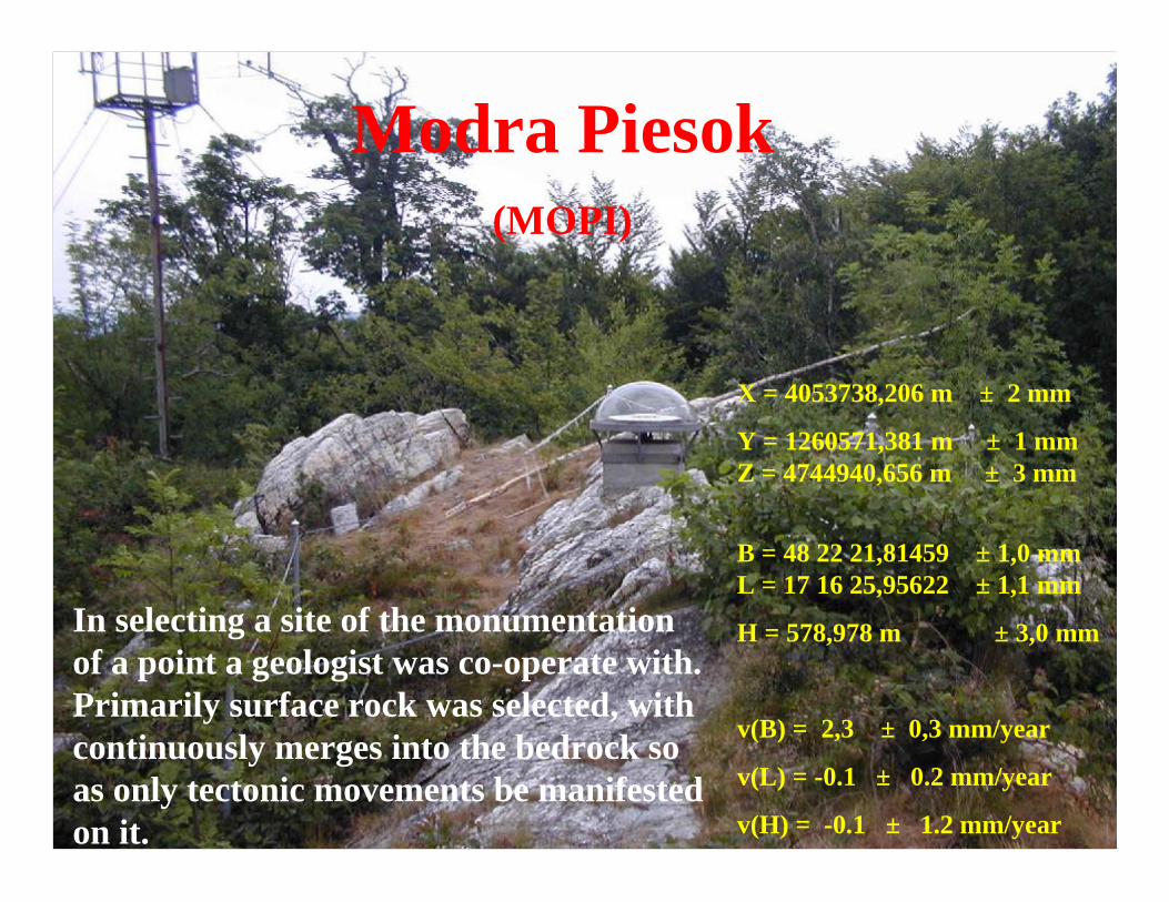
MOPIModra Piesok
(MOPI)
X = 4053738,206 m ± 2 mm
Y = 1260571,381 m ± 1 mmZ = 4744940,656 m ± 3 mm
B = 48 22 21,81459 ± 1,0 mm L = 17 16 25,95622 ± 1,1 mm
H = 578,978 m ± 3,0 mm
v(B) = 2,3 ± 0,3 mm/year
v(L) = -0.1 ± 0.2 mm/year
v(H) = -0.1 ± 1.2 mm/year
In selecting a site of the monumentationof a point a geologist was co-operate with. Primarily surface rock was selected, with continuously merges into the bedrock so as only tectonic movements be manifested on it.
Banská Bystrica(BBYS)
X = 3980358,919 m
Y = 1382292,014 mZ = 4772771,890 m
B = 48 45 06,482757 ± 2,1 mm L = 19 09 03,604789 ± 2,3 mm
H = 487,414 m ± 6,7 mm
v(B) = 20,1 ± 1,1 mm/year
v(L) = 19.6 ± 2.2 mm/year
v(H) = -7.8 ± 6.5 mm/year
Rafter into the badrock
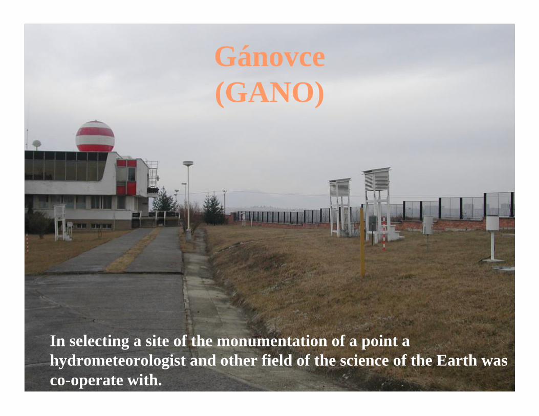
Gánovce(GANO)
In selecting a site of the monumentation of a point a hydrometeorologist and other field of the science of the Earth was co-operate with.
SGRN
GERLACH
SEOS includes 45 points with forced centering modul
Forced centering modul
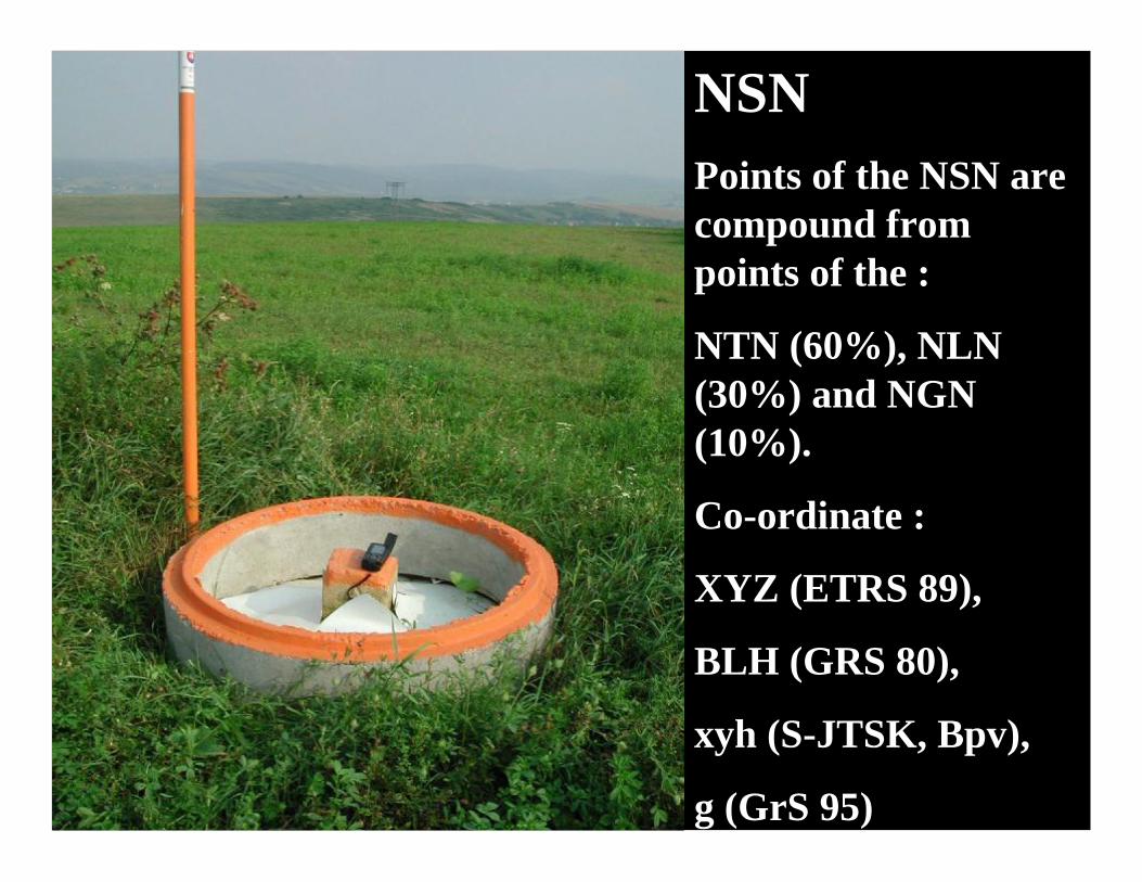
NSN
NSNPoints of the NSN are compound from points of the :
NTN (60%), NLN (30%) and NGN (10%).
Co-ordinate :
XYZ (ETRS 89),
BLH (GRS 80),
xyh (S-JTSK, Bpv),
g (GrS 95)
NSN - National Spatial Networknew geodetic control of Slovakia in ETRS89
and other activities
about 8502002building up NSN middle part of Slovakia4252001building up NSN east part of Slovakia3112000building up NSN west part of Slovakia
2291999selected control triangulation points
301997National Trigonometric Network of I order
291996National Astronometric and Geodetic Network
17 / 481993-2001
Slovak Geodynamic Reference Network
amountyearcampaigns
Relationship between ETRS 89 and S-JTSK
DMR
Q
E
E
- GRS80(a,b)
- BESSEL(a,b)
DMQ
1
2
T
AQ
Ah
AQ AQ
A [B,L,h, ]E 1
η
E 2
A [x,y],
Bh
BQ
BQBQ
B [B,L,h, ]E 1
η
B [x,y],
E 2A [B,L] B [B,L]
ηA η
B
A [XYZ]
B [XYZ]
Ph
Pη
P [x,y]
P [XYZ]
PQ
,
(1)
(1)
(1)(2)(2)
S (ETRS 89)
R (S-JTSK)
E 2
P [B,L,h, ]η
P [B,L]
E 1
Base functional relations of the reference systems
[ ] ( ) [ ] ( ) [ ] ( )
( )[ ] ( ) ( ) ( )[ ] [ ],,,,,,,
,,P,
89,
,,,
1
1
1
12
2
2
ZYXPQThLBPQLBP
LBPLByxP
ETRSPPTTEf
PQ
QEfE
EEfE
ERfJTSK
JTSK
≡+ →→∗
∗ → → →
ηη
[ ] [ ] ( ) ( )[ ] ( )
( ) ( )( )[ ] ( ) [ ]( ) ( ) ( )[ ],Q,Th,y,xP
L,BPQThH,L,BP
ThH,L,BPH,L,BPZ,Y,XP
PPJTSKE,Rf
EE,Ef
PPE
Q,EfPQ
T,EfTETRS
JTSK η
η
→∗
∗ →=+−∗
∗ →− →≡
−
−
21
2
211
1
11
0
89
S-JTSK ETRS89
S-JTSKETRS89
Reversible transformation of S-JTSK into ETRS89
A
B
C
D
A – deformed JTSK into non-deformed ETRS89
B – non-deformed ETRS89 into deformed JTSK
C - non-deformed ETRS89 into non-deformed JTSK/02
D - non-deformed JTSK/02 into non-deformed ETRS89
j
j+1
PSOC
PSOC
LDCLACLPC(GCI)
.......
.......... ............
PSOC
1
PSOC
2
PSOC
2j
PSOC
k
LDCLACLPC(STU)
LDCLACLPC(ASR)
LDCLACLPC(SEA)
LDCLACLPC
LDCLACLPC
1 2 k k+1 k+p
data centre DC
PS -permanent stationOC -operation centrumLDC -local data centreLAC -local analytical centreLPC -local processing centre