INSTRUMENTATION AND ELECTRONICS IN THE BEAM SWITCHYARD R. W. Coombes, J. N. Hall, C. A. Harris, S. K. Howry, M. J. Hu, I. C. Lutz, D. R. Olsen, R. A. Scholl, Editor, and E. J. Seppi The instrumentation for the SLAC beam switchyard (BSY) can be grouped into four basic categories: beam monitors, transport control system, equip- ment protection system, and magnet power supplies. 19-1 Introduction (RAS) Beam monitors include current-measuring toroids, beam position monitors, equipment for observing beam profile by optical (TV) means, and secondary- emission monitors for measurement of intercepted beam current on energy absorbers, for observing energy absorbers, and for observing energy spectrum. The transport control system controls magnet currents and slit and colli- mator position, and also includes associated measurement equipment for monitoring magnet currents and fields and the positions of energy-absorbing devices. This system includes a control computer for automatic setup of the transport parameters. The equipment protection system consists of sensors in the BSY to monitor radiation, temperature, water flow, the positions of energy absorbers and other movable instruments, vacuum system pressures, and so on; sensor electronics in the control room for signal conditioning; and a summary circuit to provide the necessary signals for the master machine protection circuitry at the Central Control Room (CCR) and the injector. This system protects the instruments from beam-induced damage and is not intended for protection of personnel. (Personnel protection is described in Chapter 21.) The magnet power supplies provide the pulsed and dc power for all of the magnets in the transport and deflection system. Each of these four will be described in greater detail below, but a few general remarks will be made here. Because of the high radiation levels 651
Transcript
INSTRUMENTATIONAND ELECTRONICSIN THE BEAMSWITCHYARD
R. W. Coombes, J. N. Hall, C. A. Harris, S. K. Howry, M. J. Hu,I. C. Lutz, D. R. Olsen, R. A. Scholl, Editor, and E. J. Seppi
The instrumentation for the SLAC beam switchyard (BSY) can be groupedinto four basic categories: beam monitors, transport control system, equip-ment protection system, and magnet power supplies.
19-1 Introduction (RAS)
Beam monitors include current-measuring toroids, beam position monitors,equipment for observing beam profile by optical (TV) means, and secondary-emission monitors for measurement of intercepted beam current on energyabsorbers, for observing energy absorbers, and for observing energy spectrum.
The transport control system controls magnet currents and slit and colli-mator position, and also includes associated measurement equipment formonitoring magnet currents and fields and the positions of energy-absorbingdevices. This system includes a control computer for automatic setup of thetransport parameters.
The equipment protection system consists of sensors in the BSY to monitorradiation, temperature, water flow, the positions of energy absorbers andother movable instruments, vacuum system pressures, and so on; sensorelectronics in the control room for signal conditioning; and a summarycircuit to provide the necessary signals for the master machine protectioncircuitry at the Central Control Room (CCR) and the injector. This systemprotects the instruments from beam-induced damage and is not intended forprotection of personnel. (Personnel protection is described in Chapter 21.)
The magnet power supplies provide the pulsed and dc power for all of themagnets in the transport and deflection system.
Each of these four will be described in greater detail below, but a fewgeneral remarks will be made here. Because of the high radiation levels
651
652 R. A. Scholl et a/.
associated with the interception of the beam by energy absorbers, the BSYis a closed structure under many feet of earth and concrete shielding. Thisclosed structure causes several problems in the design of equipment andsensors to be located there. First, radiation-induced chemical reactions be-tween the nitrogen, oxygen, and water vapor in the air cause a slow buildupof nitric acid fumes. These fumes attack copper and aluminum, especially inthin sections. For this reason, extensive use was made of stainless steel andother inert materials, particularly for thin elements and for components thatare difficult to replace or repair.
The high radiation levels also prevent frequent access to the BSY formaintenance purposes; delays of many days could easily be required if thedevice needing service were near a beam dump, for example. This situationmade it necessary to design each instrument for high reliability, using radi-ation-resistant components, and prevented the use of materials or parts thatrequire routine service (vacuum tubes, for example). Where this principlecould not be adhered to for reasons of economy or lack of availability ofsuitable materials, the component was placed either in an alcove or otherpartially shielded area. Certain pieces of equipment were mounted so thatremoval could be effected remotely by the use of special tools produced forthat purpose.
The layout of the major components and instruments in the BSY wasshown in Fig. 17-1. As can be seen in the figure, the switchyard is roughlyY-shaped. The upper leg leads to the "A" experimental area and is calledthe A analyzing channel; similarly, the lower leg is called the "B" channel,whereas the beam transport system collinear with the accelerator is calledthe " C " beam channel. This terminology will be used below when discussinginstrumentation differences in the various areas. For a complete discussionof the criteria and analysis of the optical properties of the system, seeChapter 17.
19-2 Beam monitors
Beam current monitors (BCM's) (DRO)
Current transformers are used for measuring the beam pulse current atvarious locations throughout the switchyard. A toroidal transformer canbe considered approximately as a current source supplying a pulse current//TV into the cable with impedance R. The output voltage on the cable is,thus,
V = jj'R (19-1)
where /= the beam pulse current; N = the number of turns on the toroid;and R = the cable impedance.
Instrumentation and electronics in the beam switchyard 653
Equation (19-1) is approximately true for a current pulse as long as
LT
whereLT _ jUjU0 JV2 • A
R ~ 2nrRin which
LT = the toroid inductancetp = the beam pulse length (1.6 usec)A = the cross section of the corer = the mean radius of the coreju = the initial permeability of the core
The droop in the output voltage is
<5K Rtn 2nr-R
sec (19-2)
y 1 .... \T2 . A P (.*•*'*)
It is desirable to have a large output voltage V and a small droop D, so itis necessary to compromise on R and N. The values selected are given inTable 19-1.
The 3-in. beam aperture current intensity monitor assembly incorpor-ates two toroids. One toroid is used in the current monitoring system. Theother is used in the precise integrator system or serves as a spare. Each coreis surrounded by an open aluminum case which acts as a Faraday shield andalso as a support for the core inside the vacuum housing. The two coreassemblies are insulated from each other and from the vacuum housing byceramic beads. The signals are brought out through standard ceramic-to-metal sealed vacuum feedthroughs to radiation-resistant, 95-ohm, fiberglass-insulated twinaxial cables. These cables extend to the upper housing of theswitchyard, where they are spliced (and matched) to RG/22/U polyethylenecables.
A current transformer with an aperture of 6.35 in. is needed in front ofbeam dump D-ll and in front of beam dump east. The core data for thistransformer are shown in Table 19-1 and the construction is very similar tothe 3-in. transformer. The 6-in. transformer is built into one housing with thefour-quadrant secondary-emission monitor. The assembly of these twomonitors is called the dump monitor.
Electronics
There are three readout systems associated with the beam current trans-formers.1 The most fundamental one is the video or dynamic scope displayof the actual beam pulse waveform. The video display provides a directobservation of the beam structure as a function of time and is used also to
654 R. A. Scholl et a/.
Table 19-1 Data on beam current monitors
Item Description
3-in. aperture current transformer
Core Four rings: 6 in. o.d., 3.675 in. i.d., each\ in. thick
Core material Mn-Zn ferrite; Ceramag 24 (StackpoleCarbon Comp.)
Beam aperture 3 in.
Initial permeability 3600 (measured value); catalog value =2500
Radiation threshold >2• 101 J ergs/g
No. of turns 48 for output signal; 1 for calibration input
Cables Output signal 95-ohm twinaxial (T-95 andRG/22/U); calibration signal 50-ohmcoaxial (B-50 and RG/63/U)
Shielding Transformer—aluminum can insulated fromvacuum housing; cables—copper shieldup to preamplifier
Inductance 24 mH
Sensitivity 2 mV/mA
Noise level 100/x.V (equivalent input noise of system)
Droop 0.8% (2-fjisec long beam pulse)
Rise time Transformer proper—10 nsec; on scope incontrol room—30 nsec.
6-in. aperture current transformer
Same as 3-in. transformerwith the following exceptions:
Core Three rings: 10 in. o.d., 7J in. i.d., each^ in. thick
Beam aperture 6.35 in.
Droop Approximately 2J%
Feedthrough Stainless steel, MgO-insulated cableswelded into housing
measure the beam peak current. The second readout system displays averagebeam current (microamperes) on a meter. By comparing average beam currentreadings at various points in the BSY, an indication of the magnitude andlocation of beam losses may be obtained. The third readout is an integratorsystem which reads average current and total charge with higher precision. Thecharacteristics of the three readout systems are summarized in Table 19-2.A block diagram of the current monitoring system is shown in Fig. 19-la.
The local preamplifier (BCM local electronics chassis) is placed as closeas possible to the current transformer but outside the switchyard shieldingso that it is accessible when the electron beam is turned off even when there
Instrumentation and electronics in the beam switchyard 655
Table 19-2 Characteristics of current monitor readout
Monitor readout Description
I. Dynamic pulse readoutDisplayAmplitude measurement
\. Average current readoutDisplayPrecisionRangeElectrons-positrons
i. Integration circuitDisplayPrecisionRangeReadouts
Electrons-positrons
On 647 oscilloscopeCan be measured with 0.3% precision using
a comparator circuit3%30 nsec with compensated cablesMin. 50-ju.A peak current, signal/noise = 1;
max. 100-mA peak currentPolarity of scope signal reverses; polarity of
comparator on control chassis can bechanged
4-in. scale meter2%0.03-100/iA full scalePolarity can be switched on front panel
Digital (Nixie tubes)0.3% relative; 1% absolute0.001 and 100/iATotal charge over any time period (manual
start-stop); Q/sec measured over 0.1,1,10 sec (ju,A); Q/pulse averaged over 10,100 beam pulses (coulombs)
Polarity can be switched on front panel
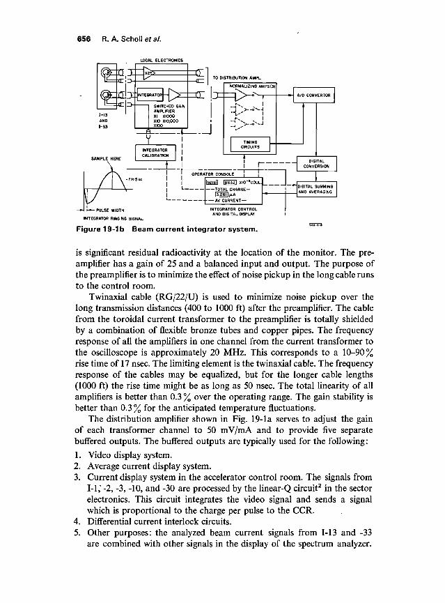
Figure 19-1 a Beam current monitoring system.
OPERATORS CONSOLELOCAL , DISTRIBUTION
PREAMPLIFIER | AMPLIFIER
2 INPUTS,
FOR 113,133
656 R. A. Scholl et al.
LOCAL ELECTRONICS
TO DISTRIBUTION AMPL.
OPERATOR CONSOLE j
— r\ \iCvJ
TIMINGCIRCUITS
1
i r
A/D CONVERTOR
— iDIG
CONVETALRSION
-PULSE WIDTH
INTEGRATOR RINGING SIGNAL
11 I52I6II 186321 XIQ-'COUL.
1 3.261 1/J.A
AV. CURRENT —
INTEGRATOR CONTROL
.»
AND AVERAGING
AND DIGITAL DISPLAY
Figure 19-lb Beam current integrator system.
is significant residual radioactivity at the location of the monitor. The pre-amplifier has a gain of 25 and a balanced input and output. The purpose ofthe preamplifier is to minimize the effect of noise pickup in the long cable runsto the control room.
Twinaxial cable (RG/22/U) is used to minimize noise pickup over thelong transmission distances (400 to 1000 ft) after the preamplifier. The cablefrom the toroidal current transformer to the preamplifier is totally shieldedby a combination of flexible bronze tubes and copper pipes. The frequencyresponse of all the amplifiers in one channel from the current transformer tothe oscilloscope is approximately 20 MHz. This corresponds to a 10-90%rise time of 17 nsec. The limiting element is the twinaxial cable. The frequencyresponse of the cables may be equalized, but for the longer cable lengths(1000 ft) the rise time might be as long as 50 nsec. The total linearity of allamplifiers is better than 0.3 % over the operating range. The gain stability isbetter than 0.3% for the anticipated temperature fluctuations.
The distribution amplifier shown in Fig. 19-la serves to adjust the gainof each transformer channel to 50 mV/mA and to provide five separatebuffered outputs. The buffered outputs are typically used for the following:
1. Video display system.2. Average current display system.3. Current display system in the accelerator control room. The signals from
1-1,' -2, -3, -10, and -30 are processed by the linear-Q circuit2 in the sectorelectronics. This circuit integrates the video signal and sends a signalwhich is proportional to the charge per pulse to the CCR.
4. Differential current interlock circuits.5. Other purposes: the analyzed beam current signals from 1-13 and -33
are combined with other signals in the display of the spectrum analyzer.
Instrumentation and electronics in the beam switchyard 657
The monitor calibration circuit (BCM system calibration chassis) cansend a pulse through the calibration winding of the transformer. Thecontrols for this circuit are integrated with all other controls in one panel(BCM video control chassis). The calibration pulse is delayed 100 /isecwith respect to the beam pulse in order to allow calibration during beamoperation. The absolute accuracy of the calibration system should be betterthan 3 %.
The basic criterion of the video display is to observe on an oscilloscopesimultaneously the output signal of any two current monitors along one beam,e.g., either 1-10 and -13 or 1-10 and -15. It is also possible to display simul-taneously monitor signals from two different beams. The total linearity andstability of all amplifiers is better than 0.3 %.
The control chassis shown in Fig. 19-la (BCM video signal control)contains thirty-six current monitor selection switches, eighteen for oscillo-scope channel 1 and eighteen for channel 2, in such a way that any monitormay be displayed on either channel. A comparator circuit in this chassisproduces a precise dc offset voltage which is used to measure the pulseamplitude.
The switches for monitor selection and two amplifiers each with gains ofx 2, x 20, and x 200, are mounted in a separate chassis (BCM video selectorchassis). The purpose of these amplifiers is to present a reasonably high volt-age which is a decimal function of the beam current (0.1 V/mA, 1.0 V/mA,10 V/mA) to the oscilloscope. They also provide filtering which can reducethe high- and low-frequency noise.
The average beam current display consists of three chassis, each of whichcontains eight separate meter displays. Each chassis is separately synchron-ized by a synchronization pulse 1.5 /^sec before beam time. The chassis has afront panel switch which allows the selection of two synchronization pulses.With this arrangement it is possible to display alternatively the current fromtwo interlaced beams on the same meter.
The maximum zero offset on the meters is due to system noise, and dcdrift is less than 10% of the most sensitive reading (0.003 //A). The precisionis about 2 %.
The purpose of the beam current integrator2'3 is to provide a precisemeasurement of the beam current at the end of the beam energy analyzingsystem. At present, one integrator readout system is built which may beswitched to read the current in either the A or B beam (1-13, 1-33). Theintegrated current can be displayed on two digital readouts. One displayrepresents the total charge over an arbitrary period of time (selected by theoperator pushing a " start" and a " stop " button). The second readout dis-plays the average beam current in either microamperes or average chargeper pulse.
The integrator circuit is located in a local electronics box as close aspossible to the current transformer but outside the radiation restricted areaand consists of a capacitor connected directly across the twinaxial cable from
658 R. A. Scholl eta/.
the second transformer of the current monitor. The sensitivity of this resonantintegration is
where C = the integrating capacitance.After the integration period tp , the capacitor and transformer inductance
LT produce a damped oscillation, as shown in Fig. 19-lb.The local switched gain amplifier is provided to build the signal level to
the highest possible value before transmission to the control room. In thecontrol room, each of the two inputs (1-13 and -33) goes to a separate ampli-fier which compensates for differences in gain as a result of differences incable length.
The integrator control and display chassis selects the integrated signalfrom any of the three monitors and connects it to the analog-to-digital(A/D) converter. The A/D converter includes a sample-and-hold circuitwhich samples the second peak of the oscillation [Fig. 19-lb]. This quantityis measured with a precision of 0.1 % and is proportional to the integral ofthe beam pulse current.
The A/D converter is a 14-bit bipolar unit with binary output. The out-put of the A/D converter goes to the digital circuit, which converts the binarysignal to a decimal form and connects to the two readouts mentioned above.
The linearity and reproducibility of the system is better than 0.1 %. Theaccuracy between the various ranges is better than 0.05 %. The absolute cali-bration will at best be of the order of 0.3 to 1 %. The minimum observablesignal is limited by the amount of coherent noise in the system.
The integrator calibration chassis discharges a precisely known amountof charge through the toroid calibration winding.
Position monitors (DRO)
A block diagram of the beam position monitor system is shown in Fig. 19-2a.The basic position detector is a microwave cavity; these cavities and thediode detectors are discussed in Chapter 15.
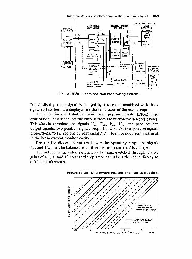
The calibration curves shown in Fig. 19-2b are based on measurementstaken on position monitors Pl and P2 during a beam test run in June 1966.They were taken with a gain setting equal to 1 . The curves depend on thesystem gain which can be adjusted internally.
The microwave position monitor has two display systems: the video ordynamic oscilloscope display system and the average or normalized displaysystem. The primary use of the microwave cavities in the switchyard is forbeam centering. A secondary use is to measure the actual displacement ofthe beam.
The output of the video display system provides the most sensitive indica-tion for beam centering. As shown in Fig. 19-2a the x and y position signals ofany two monitors may be viewed simultaneously on the Type 551 oscilloscope.
Instrumentation and electronics in the beam switchyard 659
VIDEO SIGNALDISTRIBUTION
POSITION MONITORSELECTION
ELECTRONICS
DIO
DETEC
(In A
n-rL|-r
DE
TO
cov*Si)
vf
V,o
• v,bV,oV,t,
•
PE
BALAN
CIN6
XI
±$Tt-h-
I~H MOTOR
SYSTEMSR CHASSIS
\
OPERATORS CONSOLEVIDEO
DISPLAY ON551-SCOPE
SIGNALS TOACCELERATORCONTROL ROOM
Figure 19-2a Beam position monitoring system.
In this display, the y signal is delayed by 4 /isec and combined with the xsignal so that both are displayed on the same trace of the oscilloscope.
The video signal distribution circuit [beam position monitor (BPM) videodistribution chassis] reduces the outputs from the microwave detector diodes.This chassis combines the signals Vxa, Vxb, Vya, Vyh, and produces fiveoutput signals: two position signals proportional to Ix, two position signalsproportional to ly, and one current signal / (/ = beam peak current measuredin the beam current monitor cavity).
Because the diodes do not track over the operating range, the signalsVxa and Vxb must be balanced each time the beam current / is changed.
The output to the video system may be range-switched through relativegains of 0.1, 1, and 10 so that the operator can adjust the scope display tosuit his requirements.
Figure 19-2b Microwave position monitor calibration.
VIDEO PULSE AMPLITUDE [GAIN = l] IN VOLTS
660 R. A. Schollefa/.
The control chassis (BPM video signal control) selects the cavities that aredisplayed on the scope and provides controls for balancing, phase adjust-ment, and diode switching in the microwave detector chassis.
The chassis marked microwave detector control in Fig. 19-2a is used tomultiplex the control chassis to the various position monitors.
A position signal independent of the beam current is produced in thenormalization circuits. These circuits are the same as those used for theposition monitors along the accelerator (see Chapter 15). The inputs to thesecircuits are the video position signals Ix, ly, and / signal. The outputs producethree pulses, each 500 /zsec wide. The first is proportional to the logarithm ofthe charge of the beam pulse, the second is proportional to the x displace-ment, and the third to the y displacement. They are displayed in a row onone trace of a Type 564 oscilloscope. The oscilloscope has four traces so thatthe outputs of four monitors are displayed simultaneously.
Seam profile monitors (RWC)
In the BSY, three different types of monitors are used to measure the cross-sectional profile of the beam as it is shaped by the accelerator and the trans-port system. Although the principles of operation of the three devices arequite different, they share the common characteristic of producing a beam oflight, which when focused onto a suitable detector (in this case the vidicontube of a television camera) gives an image of the profile of the beam. Thethree sources of light are synchrotron radiation, Cerenkov radiation, andbeam-induced phosphorescence. Each effect and the way it is used in theBSY will be described separately. It should be mentioned, however, that theoptical and TV system is basically the same for the three monitors. The lightis reflected by a series of mirrors from its source in the lower half of the doubletunnel structure of the switchyard to a radiation-resistant telescope aridtelevision camera mounted in a shielded sleeve in the upper part of the tunnel.
SYNCHROTRON LIGHT. Electromagnetic radiation is emitted tangentially tothe path of an electron deflected in a magnetic field. For most of the magnetsin the beam switchyard, the wavelength of this radiation covers the visiblespectrum. This phenomenon has been used after the first bending magnetB-10 in the A-beam of the switchyard as a nonintercepting means of visualobservation of the beam spot.4 The radiation covers a wide frequency spec-trum which is dependent upon the bending radius in the magnet and whichshifts toward the shorter wavelengths with the third power of the beamenergy:
3
L = 5.59R- l-l
where Xc is the shortest wavelength in angstroms radiated, E is the energy ingigaelectron volts, and R is the bending radius in meters.
Instrumentation and electronics in the beam switchyard 661
V-SHAPEDSYNCHROTRONLIGHT CHAMBER
QUARTZ WINDOW
PIS1-30
METAL MIRROR
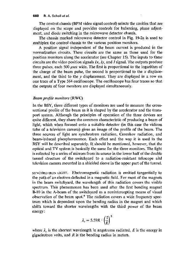
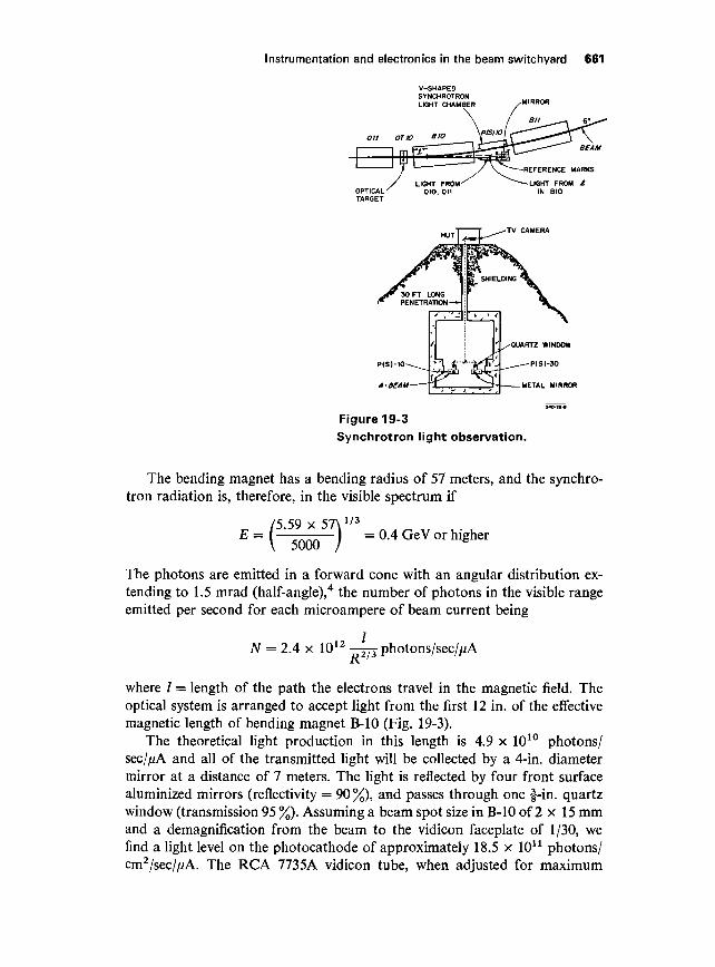
Figure 19-3Synchrotron light observation.
The bending magnet has a bending radius of 57 meters, and the synchro-tron radiation is, therefore, in the visible spectrum if
E =5 59 x 57\1/3
I = 0.4 GeV or higher5000
The photons are emitted in a forward cone with an angular distribution ex-tending to 1.5 mrad (half-angle),4 the number of photons in the visible rangeemitted per second for each microampere of beam current being
N = 2.4 x 10¹²
R2,: photons/sec//iA
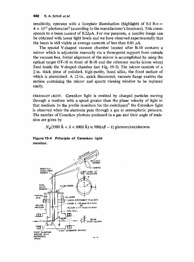
where / = length of the path the electrons travel in the magnetic field. Theoptical system is arranged to accept light from the first 12 in. of the effectivemagnetic length of bending magnet B-10 (Fig. 19-3).
The theoretical light production in this length is 4.9 x 10¹⁰ photons/sec//j.A and all of the transmitted light will be collected by a 4-in. diametermirror at a distance of 7 meters. The light is reflected by four front surfacealuminized mirrors (reflectivity = 90 %), and passes through one f-in. quartzwindow (transmission 95 %). Assuming a beam spot size in B-10 of 2 x 15 mmand a demagnification from the beam to the vidicon faceplate of 1/30, wefind a light level on the photocathode of approximately 18.5 x 10¹¹ photons/cm2/sec//iA. The RCA 7735A vidicon tube, when adjusted for maximum
662 R. A. Scholl et al.
sensitivity, operates with a faceplate illumination (highlight) of 0.1 ft-c =4 x 10¹¹ photons/cm2 (according to the manufacturer's brochure). This corre-sponds to a beam current of 0.22/^A. For our purposes, a useable image canbe obtained with lower light levels and we have observed experimentally thatthe beam is still visible at average currents of less than 0.01 ^A.
The special V-shaped vacuum chamber located after B-10 contains amirror which is adjustable manually via a three-point support from outsidethe vacuum box. Initial alignment of the mirror is accomplished by using theoptical target OT-10 in front of B-10 and the reference marks (cross wires)fixed inside the V-shaped chamber (see Fig. 19-3). The mirror consists of a5-in. thick piece of polished, high-purity, fused silica, the front surface ofwhich is aluminized. A 12-in., quick disconnect, vacuum flange enables thesection containing the mirror and quartz viewing window to be replacedeasily.
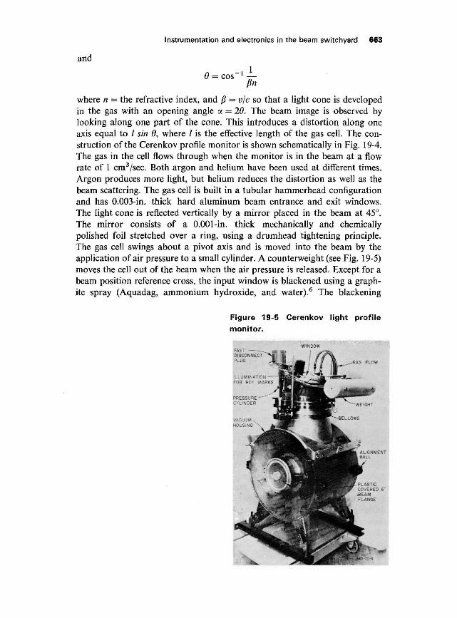
CERENKOV LIGHT. Cerenkov light is emitted by charged particles movingthrough a medium with a speed greater than the phase velocity of light inthat medium. In the profile monitors for the switchyard5 the Cerenkov lightis observed when the electrons pass through a gas at atmospheric pressure.The number of Cerenkov photons produced in a gas and their angle of emis-sion are given by
AT^(3500 A < A < 6000 A) w 900(nj5 - 1) photons/cm/electron
Figure 19-4 Principle of Cerenkov lightmonitor.
PIVOTINGAXIS ^BELLOWS
-QUICK DISCONNECT FLANGES
-ARGON a = 48 mrod (R a 11cm)OR
HELIUM a =17mrad (R»4cm)
-GAS CELL
CROSS-SECTIONj—
-0.003 ALUMINUMWINDOW WITHREFERENCECROSS
^0.001" ALUMINUM MIRROR
Instrumentation and electronics in the beam switchyard 663
and
0 = cos~1 —fin
where n = the refractive index, and ft = v/c so that a light cone is developedin the gas with an opening angle a = 20. The beam image is observed bylooking along one part of the cone. This introduces a distortion along oneaxis equal to / sin 9, where / is the effective length of the gas cell. The con-struction of the Cerenkov profile monitor is shown schematically in Fig. 19-4.The gas in the cell flows through when the monitor is in the beam at a flowrate of 1 cm3/sec. Both argon and helium have been used at different times.Argon produces more light, but helium reduces the distortion as well as thebeam scattering. The gas cell is built in a tubular hammerhead configurationand has 0.003-in. thick hard aluminum beam entrance and exit windows.The light cone is reflected vertically by a mirror placed in the beam at 45°.The mirror consists of a 0.001-in. thick mechanically and chemicallypolished foil stretched over a ring, using a drumhead tightening principle.The gas cell swings about a pivot axis and is moved into the beam by theapplication of air pressure to a small cylinder. A counterweight (see Fig. 19-5)moves the cell out of the beam when the air pressure is released. Except for abeam position reference cross, the input window is blackened using a graph-ite spray (Aquadag, ammonium hydroxide, and water).6 The blackening
Figure 19-5 Cerenkov light profile
monitor.
664 R. A. Schollefa/.
Table 19-3 Comparison of two types of multiscreen monitors
Characteristics Cerenkov cell ZnS screen
Sensitivity
Spot definitionMax. apertureMaterial in beam
Rad. length in Beam
Mechanical
Expected life
(He)10-9 A/cm2
(Ar) 3x 1CT10 A/cm2
1 mm3 in. in diameter2 Al windows 0.003 in.;
1 Al mirror 0.001 in.;20 cm gas; 0.001 in.graphite (Aquadag) onone window
6X 10⁻³rad / (Ar);2x 10⁻³rad/(He)
Moved into beam by airpressure, out by gravity
M irror 1.5 X 10⁴ jiiA hour/cm2
10-9 A/cm2
1 mm8 in. wide, 2 in. long0.002-in. Al foil at 65° or
90° to beam0.001-in. and 0.004-in.
thick zinc sulfideSylvania (P-402)
1.3 to 3.5 x 10⁻³ rad /
Selected and operated byelectric motors
10 /xA hour/cm2 perscreen
carbon is molecularly bonded to the window and is, therefore, permanent.The cross can be illuminated with a lamp mounted outside the viewing win-dow. Table 19-3 gives the characteristics of both the Cerenkov cell and thezinc sulfide screen profile monitors.
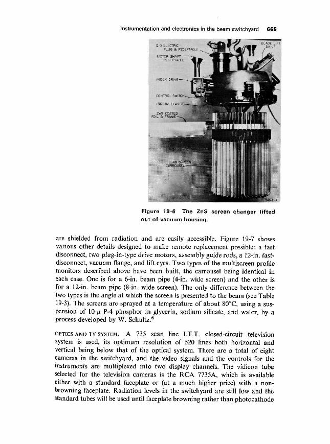
ZINC SULFIDE SCREENS. Zinc sulfide screens are easy to make and have goodsensitivity; however, they have the disadvantage of losing luminescence afterexposure to an integrated beam current of about 10 juA/hour/cm2. Thereplacement of such screens is a difficult task in the switchyard because ofthe severely limited access. For this reason, an automatic device has beendeveloped that will replace the screens after they have become inactive.Several possible mechanisms have been considered, among which are a largedisk with-its axis of rotation tilted 45° with respect to the beam, and the filmroll principle. The mechanism adopted for the switchyard is a carrousel withforty-eight independent screens, shown in Fig. 19-6. The forty-eight screenarms hang on balls in the slotted rim of a 10-in. wheel. The screen frames canbe raised into the beam by the blade lift mechanism. The U-shape of theframe ensures that the beam is intercepted only by the 0.002-in. thick zincsulfide-coated aluminum foil. The index drive mechanism rotates the wheel7.5° so that a new screen comes into the lift position. The carrousel can beremoved from its housing when all the screens have been used. The individualscreen frames can be lifted out of the slotted rim for replacement. The imageof the beam spot on the screen and position reference marks are observedthrough a fused silica vacuum window at the top of the light pipe and afront surface mirror at the lower end of the light pipe. The adjustable mirroron top of the light pipe and the two drive motors, shown in Fig. 19-7, pro-trude into a slot in the 2-ft thick concrete shielding floor. In this way they
Instrumentation and electronics in the beam switchyard 665
Figure 19-6 The ZnS screen changer liftedout of vacuum housing.
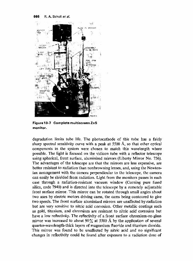
are shielded from radiation and are easily accessible. Figure 19-7 showsvarious other details designed to make remote replacement possible: a fastdisconnect, two plug-in-type drive motors, assembly guide rods, a 12-in. fast-disconnect, vacuum flange, and lift eyes. Two types of the multiscreen profilemonitors described above have been built, the carrousel being identical ineach case. One is for a 6-in. beam pipe (4-in. wide screen) and the other isfor a 12-in. beam pipe (8-in. wide screen). The only difference between thetwo types is the angle at which the screen is presented to the beam (see Table19-3). The screens are sprayed at a temperature of about 80°C, using a sus-pension of 10-/i P-4 phosphor in glycerin, sodium silicate, and water, by aprocess developed by W. Schultz.6
OPTICS AND TV SYSTEM. A 735 scan line I.T.T. closed-circuit televisionsystem is used, its optimum resolution of 520 lines both horizontal andvertical being below that of the optical system. There are a total of eightcameras in the switchyard, and the video signals and the controls for theinstruments are multiplexed into two display channels. The vidicon tubeselected for the television cameras is the RCA 7735A, which is availableeither with a standard faceplate or (at a much higher price) with a non-browning faceplate. Radiation levels in the switchyard are still low and thestandard tubes will be used until faceplate browning rather than photocathode
666 R. A. Scholl et a/.
Figure 19-7 Complete multiscreen ZnSmonitor.
degradation limits tube life. The photocathode of this tube has a fairlysharp spectral sensitivity curve with a peak at 5500 A, so that other opticalcomponents in the system were chosen to match this wavelength wherepossible. The light is focused on the vidicon tube with a reflector telescopeusing spherical, front surface, aluminized mirrors (Liberty Mirror No. 756).The advantages of the telescope are that the mirrors are less expensive, arebetter resistant to radiation than nonbrowning lenses, and, using the Newton-ian arrangement with the camera perpendicular to the telescope, the cameracan easily be shielded from radiation. Light from the monitors passes in eachcase through a radiation-resistant vacuum window (Corning pure fusedsilica, code 7940) and is directed into the telescope by a remotely adjustablefront surface mirror. This mirror can be rotated through small angles abouttwo axes by electric motors driving cams, the cams being contoured to givetwo speeds. The front surface aluminized mirrors are unaffected by radiationbut are very sensitive to nitric acid corrosion. Other metallic coatings suchas gold, titanium, and chromium are resistant to nitric acid corrosion buthave a low reflectivity. The reflectivity of a front surface chromium-on-glassmirror was increased to about 90 % at 5500 A by the application of severalquarter-wavelength-thick layers of magnesium fluoride and titanium dioxide.This mirror was found to be unaffected by nitric acid and no significantchanges in reflectivity could be found after exposure to a radiation dose of
Instrumentation and electronics in the beam switchyard 667
1010 ergs/g. Because of the uncertainty in estimating the nitric acid vaporconcentration in the switchyard, it was felt that the expense of these mirrorscould not be justified. However, a fully dielectric commercial mirror (LibertyMirror No. 90-500) has been purchased and installed on one of the Cerenkovcells for further evaluation.
The telescopes are designed to give an overall magnification on the 17-in.TV monitor between 1 and 2 times the actual beam size. The spherical mir-rors vary in focal length between 10 and 20 in. for the different monitors inthe switchyard. The telescopes are constructed in such a way that they willaccept any 4^-in. diameter mirror in this range. Coarse focusing is providedby means of a thumbscrew on each telescope; fine focusing is provided byremote control of the position of the vidicon tube inside the TV camera.
In the case of the zinc sulfide screen changers, where viewing angles intro-duce different distortions along the two axes, an elliptical disk is mountedjust out of the beam path in such a way that it corresponds to a circularbeam spot and can be seen on the TV monitor when there is no screen in thebeam. By adjusting the TV monitor so that this disk appears circular, thedistortion of the system can be corrected.
Secondary-emission monitors (SEM's) (JNH)
Low-energy secondary electrons (<30 eV) are emitted from the surfaces ofmaterial when it is traversed by high-energy (>75 keV) charged particles.The secondary emission shows little dependence on primary particle energyabove 150 keV. It is linear with current and there is no saturation. SEM'sare useful in the switchyard for their linearity and wide dynamic range butcan be used only where an intercepting-type monitor is permissible.
Secondary-emission monitors are used in the switchyard, in the followingapplications:
1. The tune-up spectrum monitor (TSM).2. A- and B-beam spectrum analyzers (SA).3. For beam centering into the high-power dumps (four-quadrant SEM)
and collimators.4. On the slits to provide spectrum centering information (spectrum drift
indicator—SDI).5. Applications 3 and 4 above are also used to provide interlock signals to
the summary interlock system for equipment protection.
The theoretical secondary-emission coefficient, rj, is approximately 4% foraluminum. The coefficient is very dependent on surface conditions. Aluminumfoils are used for all SEM's in the switchyard, and for calculation purposes r\was assumed to be 3 %.
SEM FOILS ON SLITS, COLLIMATORS, AND TUNE-UP DUMP. Sets of three parallelSEM foil emitters are mounted on the front and back of C-0, C-l, and SL-10
668 R. A. Scholl et al.
and on the front of SL-31. Two of the foils on the front of C-0, C-l, andSL-10 are experimental gold-plated conduction foils. Two sets of parallelSEM foils are mounted at each edge of the tune-up dump. These protect thedump edge from beam powers above 50 kW.
FOUR-QUADRANT SEM (4-Q SEM). This SEM is a circular structure 8 in. o.d. x3 in. i.d. It is divided into four quadrants: top, bottom, right, and left. Eachquadrant consists of a set of three 0.005-in. thick emitting foils in parallel.
A 4-Q SEM is mounted in front of the window of the A-beam dump andbeam dump east. The monitor is used to steer the beam into the center of thewindow. The permissible power density on the window is highest in thecenter. Very intense beams must be carefully centered to avoid overstressingthe window near its edge.
ELECTRONICS. The SEM electronics provide two signals, an interlock leveland a dynamic presentation of SEM signals. Each foil is connected to anRC integrator (T = 200 msec). The integrator voltage is monitored by avariable threshold comparator ( + 20 mV to + 2.0 V). The comparator out-puts are connected to an OR gate and used as the SEM interlock signal.
For dynamic presentation, the integrator voltages may be viewed on anoscilloscope which is connected to the electronics through a multiplexer anda selector panel (see Fig. 19-8).
Beam spectrum instrumentation (JNH)
A low-resolution spectrum measurement can be made with the tune-upspectrum monitor S-10, located in front of the tune-up dump D-10. A moreprecise measurement of the deflected A- and B-beam spectrum is made withidentical analyzers S-ll and -31, located in front of the slits SL-10 and -31.(See Table 19-4.)
Any combination of four out of the 26 video signals canbe displayed on a Tektronix 551 scope
30 pV
30 nsec
See detail 2 of spectrum monitor
Every beam pulse
100 nsec; sample can be taken at any point of beampulse length : 0-2.2 /j-sec
670 R. A. Scholl et al.
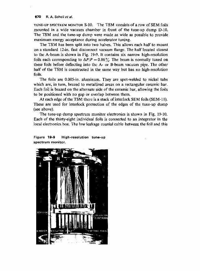
TUNE-UP SPECTRUM MONITOR S-10. The TSM consists of a row of SEM foilsmounted in a wide vacuum chamber in front of the tune-up dump D-10.The TSM and the tune-up dump were made as wide as possible to providemaximum energy acceptance during accelerator tuning.
The TSM has been split into two halves. This allows each half to mounton a standard 12-in. fast disconnect vacuum flange. The half located closestto the A-beam is shown in Fig. 19-9. It contains six narrow high-resolutionfoils each corresponding to AP/P = 0.86 %. The beam is normally tuned onthese foils before deflecting into the A- or B-beam vacuum pipe. The otherhalf of the TSM is constructed in the same way but has no high-resolutionfoils.
The foils are 0.005-in. aluminum. They are spot-welded to nickel tabswhich are, in turn, brazed to metallized areas on a rectangular ceramic bar.Each foil is brazed on the alternate side of the ceramic bar, allowing the foilsto be positioned with no gap or overlap between them.
At each edge of the TSM there is a stack of interlock SEM foils (SEM-11).These are used for interlock protection of the edges of the tune-up dump(see above).
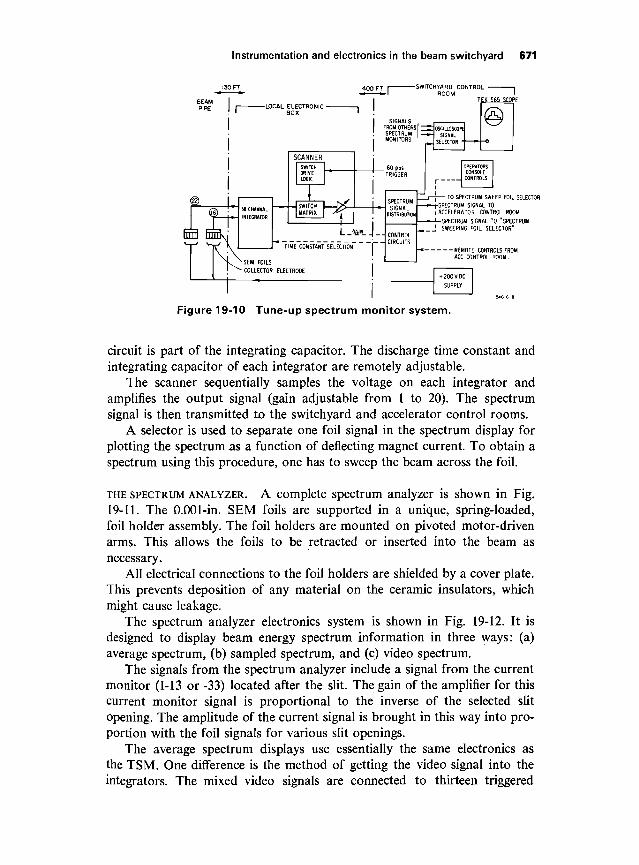
The tune-up dump spectrum monitor electronics is shown in Fig. 19-10.Each of the thirty-eight individual foils is connected to an integrator in thelocal electronics box. The low leakage coaxial cable between the foil and this
Instrumentation and electronics in the beam switchyard 671
SWITCHYARD CONTROL 1ROOM I
TEK 565 SCOPE
CONTROLCIRCUITS
TO SPECTRUM SWEEP FOIL SELECTOR
SPECTRUM SIGNAL TO
I ACCELERATOR CONTROL ROOM
SPECTRUM SIGNAL TO "SPECTRUM
_ _J SWEEPING FOIL SELECTOR"
\i\REMOT
ACC CO
+ 200VDC
SUPPLY
Figure 19-10 Tune-up spectrum monitor system.
circuit is part of the integrating capacitor. The discharge time constant andintegrating capacitor of each integrator are remotely adjustable.
The scanner sequentially samples the voltage on each integrator andamplifies the output signal (gain adjustable from 1 to 20). The spectrumsignal is then transmitted to the switchyard and accelerator control rooms.
A selector is used to separate one foil signal in the spectrum display forplotting the spectrum as a function of deflecting magnet current. To obtain aspectrum using this procedure, one has to sweep the beam across the foil.
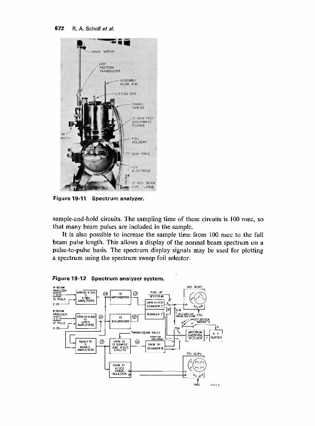
THE SPECTRUM ANALYZER. A complete spectrum analyzer is shown in Fig.19-11. The 0.001-in. SEM foils are supported in a unique, spring-loaded,foil holder assembly. The foil holders are mounted on pivoted motor-drivenarms. This allows the foils to be retracted or inserted into the beam asnecessary.
All electrical connections to the foil holders are shielded by a cover plate.This prevents deposition of any material on the ceramic insulators, whichmight cause leakage.
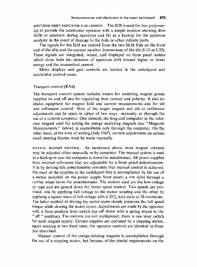
The spectrum analyzer electronics system is shown in Fig. 19-12. It isdesigned to display beam energy spectrum information in three ways: (a)average spectrum, (b) sampled spectrum, and (c) video spectrum.
The signals from the spectrum analyzer include a signal from the currentmonitor (1-13 or -33) located after the slit. The gain of the amplifier for thiscurrent monitor signal is proportional to the inverse of the selected slitopening. The amplitude of the current signal is brought in this way into pro-portion with the foil signals for various slit openings.
The average spectrum displays use essentially the same electronics asthe TSM. One difference is the method of getting the video signal into theintegrators. The mixed video signals are connected to thirteen triggered
672 R. A. Scholl et a/.
S 12 IMCH BEAM
*»r PIPE FLANGE
Figure 19-11 Spectrum analyzer.
sample-and-hold circuits. The sampling time of these circuits is 100 nsec, sothat many beam pulses are included in the sample.
It is also possible to increase the sample time from 100 nsec to the fullbeam pulse length. This allows a display of the normal beam spectrum on apulse-to-pulse basis. The spectrum display signals may be used for plottinga spectrum using the spectrum sweep foil selector.
Instrumentation and electronics in the beam switchyard 673
SPECTRUM DRIFT INDICATOR ELECTRONICS. The SDI is Used for tWO pUFpOSCS I
(a) to provide the accelerator operator with a simple monitor showing slowdrifts in spectrum during operation and (b) as a backup for the spectrumanalyzer in the event of damage to the foils or other delicate parts.
The signals for the SDI are derived from the two SEM foils on the frontend of the slits and the current monitor downstream of the slit (1-13 or 1-33).These signals are integrated, mixed, and displayed on three panel meterswhich show both the direction of spectrum drift toward higher or lowerenergy and the transmitted current.
Meter displays and gain controls are located in the switchyard andaccelerator control room.
Transport control (RAS)
The transport control system includes means for switching magnet powersupplies on and off and for regulating their current and polarity. It also in-cludes equipment for magnet field and current measurements and for slitand collimator control. Most of the major magnet and slit or collimatoradjustments can be made in either of two ways—manually or through theuse of a control computer. One element, the long-coil integrator in the refer-ence magnet used for setting the energy analyzing magnets (see " MagneticMeasurements" below), is controllable only through the computer. On theother hand, at the time of writing (July 1967), current adjustments on certainsmall steering dipoles must be made manually.
MANUAL MAGNET CONTROL. As mentioned above, most magnet currentsmay be adjusted either manually or by computer. The manual system is usedas a backup in case the computer is down for maintenance. All power supplieshave internal references that are adjustable by a front panel potentiometer.It is by driving this potentiometer remotely that manual control is achieved.On most of the supplies in the switchyard this is accomplished by the use ofa motor mounted on the power supply front panel; a rim drive through arubber wheel turns the potentiometer. The motors used are the low-voltagedc type and are geared down for better speed control. Two speeds are pro-vided, one by applying full voltage to the motor winding and the other byapplying a square wave of full voltage with a 20% duty cycle at 20 counts/sec.The latter method of driving the motor more closely preserves the full speedtorque while slowing the motor down. Adjustments are made by the operatorwith a three-position lever switch (up-off-down with a spring return to the"off" position). The controls are not multiplexed; there is one lever switchfor each magnet supply. Certain supplies are operated by a stepping motor,again running at two fixed rates; the operator controls are identical to thosejust described.
Manual control of the energy-defining magnets is accomplished throughthe use of a stepping motor, but because of the special requirements on the
674 R. A. Schollefa/.
rate and magnitude of the current changes (see Chapter 18) the operatorcontrols are different from those described above. In this case a set of rotaryswitches can be set by the operator to correspond to the number of steps themotor is to take. The motor will start on pushbutton command and stop afterhaving taken the number of steps indicated by the switches. The motor runsat a fixed rate corresponding to a rate of change of current of 6 A/sec in themagnets. One control panel is used for both the A and B magnet systems.
Readback of magnet current is accomplished in two ways, dependingupon the type of power supply (dc or pulsed). The dc currents are convertedto voltages by ohmic shunts and are subsequently read by a digital volt-meter, switched by a relay scanner. Any dc signal from the switchyard canbe read to 0.02 % absolute accuracy in this way. Pulsed magnet currents areconverted to voltage by a pulse transformer and are read by a sample-and-hold circuit and an analog-to-digital converter capable of reading rates upto 360 pulses sec. This counter is switched by a second relay scanner, andabsolute accuracy is better than 0.1 %. The pulsed system has one fixed rangeof 10 V full scale with a resolution of 0.001 V; the dc system has ranges of1000, 100, 10, 1.0, 0.1. and 0.01 V full scale with a resolution of five digits(0.1 ^V on the smallest range).
MAGNETIC MEASUREMENTS (RAS). A system for remote measurement ofmagnetic fields has been provided. This system includes residual field detec-tors, NMR probes, and flux loop integrators (an integrator connected to aloop around the magnet yoke).
The residual field detector is a flux-gate magnetometer. The probe con-sists of a pair of strips of high-permeability magnetic material, each woundwith a "primary" coil. The primaries are connected in series, opposing. A1000-Hz signal applied to the primary windings then alternately saturatesthe cores in opposite directions. A pickup "secondary" coil is woundaround both strips. The signal in this coil (to first order) does not containany 1000-Hz components because of the opposing primary currents. If asmall dc magnetic field is applied parallel to the strips, a 2000-Hz voltageappears across the secondary, because on each half-cycle of the primarycurrent one of the cores is easier to saturate than the other, " unbalancing "the primary currents. This signal is passed through a 2000-Hz, narrow bandfilter and applied to a high gain amplifier. The output of the amplifier issynchronously detected using the primary signal for phase reference. Theresulting dc output is proportional to the field in the probe and is displayedon a panel meter. Sensitivity of the meter is about 2.5 G full scale. Thismethod was chosen to allow the use of a passive probe structure; the probeconsists entirely of radiation-resistant materials and can be operated up to2000 ft from the electronics.
Nuclear magnetic resonance probes are placed in the energy-definingmagnets B-10 to B-13 and B-30 to B-32, and in the reference magnets (tworeference magnets B-100 and -300 are placed in the control room building
Instrumentation and electronics in the beam switchyard 675
and are electrically in series with the energy-defining magnets in the A-beamand B-beam). The N M R circuit is a modified Pound-Watkins-Knightmarginal oscillator7 and offers no unusual design features. The probe itselfconsists of a quartz tube with a volume of 0.03 cm3 surrounded by a solenoid,which acts as the RF circuit of the oscillator. The liquid is a 0.1-mole solutionof MnSO4 in saturated LiCl2 in water and provides two resonances: *H at4.2577 MHz/kG and 7Li at 0.23487 MHz/kG. This double-resonance tech-nique allows coverage of a wider field range without frequency range switch-ing in the electronics. No sweep coils were provided because the dimensionsof the probe had to be made as small as possible (|-in. o.d.) to avoid inter-action with the beam in the narrow magnet gaps. A sweep field is obtainedby shunting the magnet with a transformer operated from the 60-Hz powerline via dc blocking capacitors. A signal-to-noise ratio of 10 to 1 is obtainedin the final system with connecting cables as long as 1000 ft.
A simple integrator system has been provided to allow crude field measure-ments in the dc magnets. The purpose of these measurements is to allowdetection of shorts or other changes in the magnet coils at a remote location.The pickup coils (flux loops) consist of several turns around the return yokesof the magnets. These coils are connected by a selector to a stable dc inte-grator. The system is used as follows. The magnet is turned on to a presetcurrent and the integrating capacitor discharged. The magnet is then turnedoff, and the resulting output from the integrator is read on a digital voltmeter.The system measures magnet characteristics to better than 1 %.
Stationary flux loops on the pulsed magnets PM1 through PM5 are usedto integrate the magnetic field in these magnets every beam pulse. The out-put is used not only to measure the field but also to interlock the beam inthe event of misfiring of a magnet modulator (see Section 19-3).
A special rotating flux coil is used in the reference magnets B-100 and-300. This coil can be rotated 180° in the gap of these magnets. The coil out-put voltage is connected to a voltage-to-frequency converter, and the numberof pulses emerging from the converter is proportional to the integral of thefield along the coil length. Because the coil is made long enough to includemost of the fringing fields, it measures the J B dl to high accuracy. The absoluteaccuracy of the method is not well defined because of the lack of a suitablecomparison standard, but rms deviations in the measurement are typicallyless than 5 parts in 105 over a 1-hour interval. The rotating flux coil is usedby the computer (see below) to set the energy acceptance of the BSY.
COMPUTER SYSTEM (RAS, SKH). The transport control system includes asmall digital computer to aid in setting up the complex set of parameters inthe BSY. The computer (SDS 925) has an 8192-word core memory (24 bitsper word) and a 1.75-^sec cycle time; it is a fully parallel, binary orientedmachine. Standard peripheral equipment includes a card reader (200 cards/min), a card punch (100 cards/min), and a pair of teletypes, one in the BSYcontrol room and one in the CCR.
676 R. A. Scholl et a/.
Through the use of a number of SLAC-built interfaces, the computer canread, log, and control status information; control magnet, slit, and colli-mator settings; determine the energy of the various beams in the switchyardto better than 0.05%; and communicate with a larger computer (SDS 9300)in the experimental areas. The operation of these interfaces and associatedequipment will be described below.
The interlock and status scanner reads, every beam pulse (2.8 msec),the 1008 two-state status signals in the BSY. The computer scans thesesignals, detects changes in them, and notifies the operator of the changes.The time required by the computer for scanning, detecting, and identifyingthe signals is less than 400 /^sec. Additional time is required for processing ifchanges occur.
The scanner is basically a digital multiplexing system controlled by thecomputer; it transfers 1008 input signals to its output, sixteen signals at atime. Along with each group of sixteen data signals, 6 bits of address informa-tion are presented at the output to identify the group being transferred. Thus22 bits of information are presented to the computer at a time. The computermust accept 63 such transfers to get all of the 1008 signals. When all of theinformation is stored in the computer memory, the data are compared bitby bit with the previous scan, and the changes recorded. At the time ofwriting (July 1967) the changes are printed on a small digital printer (maxi-mum speed »20 lines/sec), but plans are underway to add an oscilloscopedisplay to the system, which would be used to provide a more sophisticatedpresentation.
Computer magnet control involves five basic equipment modules:digital-to-analog converters to control magnet currents; analog-to-digitalconversion equipment to read those currents; the long flux coil (see "Mag-netic Measurements," above) interface to read J B dl in the energy-definingmagnets; the "tune box" to provide the operator with facility for makingsmall changes in the settings; and a set of status control channels for control-ling magnet power supply " on-off " and reversing. Two interfaces are usedfor digital-to-analog conversion, and each operates a different type ofconverter. The most common type consists of a 15-bit binary resistor ladderswitched by mercury-wetted reed relays. The relays are of the magneticlatching type, and thus form the memory as well as the switching and isola-tion functions. Reference voltage for the resistor ladder is supplied by ahighly stable ( + 0.01 %/24 hours) power supply that is shielded and guardedfrom the chassis ground. The resistor ladder contains thirty-one resistors,matched to ±0.002%, and is also guarded. The 15-bit resolution allows stepsof 1 part in 32,768 of the full-scale output voltage of 10 V, or about 300 ^v.The present system includes twenty-six such converters, with provision toextend this number to sixty-four.
The energy-analyzing magnets, however, have one special requirementwhich precludes the use of this type of converter. The high energy of theelectron beam (24 GeV) requires eight 3-meter magnets to deflect the beam
Instrumentation and electronics in the beam switchyard 677
24° in the analyzing system (for A-beam; the B-beam uses four magnets todeflect the beam 12°). These magnets are connected electrically in series,along with a reference magnet (which is placed in the control room formeasurement purposes). In order to ensure accurate tracking of the magneticfield, a necessity if the reference magnet measurements are to be meaningful,the current in these magnets must be changed at a relatively slow rate(0.75%/sec).
The digital-to-analog converters mentioned above inherently producetransients that far exceed this rate. Therefore, these magnets are controlledby a reference voltage from a multiturn potentiometer driven by a digitalstepping motor. The mechanical nature of such a system precludes transientslarger than about 0.003% in amplitude. The interface contains a pair ofcounters (one for A-beam and one for B-beam) which are loaded by thecomputer with the number of steps the motor is to take. The interface detectsthe sign of the number (it is loaded in two's complement) and, if negative,counts the counter up and the motor counterclockwise; if it is positive, theinterface counts the counter down and the motor clockwise. A pulse iscounted by the counter for each pulse sent to the motor. When the counterreaches zero, the clock pulses stop (stopping the motor) and the computeris interrupted.
Readback of magnet currents is accomplished by two methods. In thecase of dc magnets, the currents are measured by shunts («1.2 x 10~3 ohm),and the shunt signals are switched through a precision relay scanner to adigital voltmeter, where they are digitized to an accuracy of better than0.01 %. Of course, any dc signal can be read through this system. For thepulsed magnets, a solid-state differential multiplexer and a fast analog-to-digital converter with a sample-and-hold circuit provide the computer withmeasurement ability. The computer selects both the channel and triggertime of the sample-and-hold circuit.
The long flux coil interface contains circuits to control the motor andclutches on the coil mechanism, and to count the pulses from the voltage-to-frequency converter. The circuits work in the following way. Upon issuanceof a command by the computer, the motor starts to turn and the clutchengages, starting the coil in motion. The output of the coil is connectedto a voltage-to-frequency converter with high stability. Since the output ofthe converter is a train of pulses the frequency of which is proportionalto the input voltage, the number of pulses is proportional to the integral ofthe input voltage. These pulses are counted by a register in the interface, and aset of microswitches on the coil mechanism stops the motor and provides aninterrupt to the computer when the rotation has ended. Upon interruptionthe computer reads the number in the register, resets it, and starts the coilrotating in the opposite direction. The program always averages two success-ive "flips" of the coil to eliminate the effect of zero drift error in the voltage-to-frequency converter. The resulting number is precisely proportional to theJ B dl in the magnet, which is, in turn, proportional to the energy of a particle
678 R. A. Scholl et al.
passing through the center of the slit. Root-mean-square deviations of themeasurement are typically less than 5 x 10"5 over a 1-hour period, with thecoil making three flips a minute.
The "tune-box," or magnet manual control panel, consists of twenty-four pushbuttons, one lever switch (three position momentary), and a speedcontrol knob. Interrupts are sent to the computer by this panel wheneverthe lever switch is raised or lowered. The rate at which these interrupts aresent to the computer is controlled by the speed control (1 per switch opera-tion, or a steady 1, 5, or 25 per second). When so programmed, the computerwill interpret the selected pushbuttons as magnet supplies, inspect the push-buttons, and increment or decrement the magnet currents selected dependingupon the position of the lever switch. There are two such panels provided.Since the interface is designed such that the interrupt is not required for thecomputer to inspect the pushbuttons, this panel can also be used in otherways, one of which is to print out on the typewriter the currents (in equivalentgigaelectron volts) of all magnets selected. This is done through a typewriterinstruction (see the discussion of the computer program below). The tune-boxwas provided primarily to allow the operator to make small adjustments to themagnet currents in a manner more natural than typing a series of instructionson the computer typewriter.
The final interface used for magnet control is a set of sixteen mercury-wetted relays (the system is expandable to sixty-four such sets) of which thepositions are individually under computer control. This interface allows thecomputer to turn on and off and reverse power supplies, or to control otherstatus in the switchyard and research areas.
A computer-computer link has been designed between the SDS 925 inthe switchyard and the SDS 9300 in the experimental area, about 1000 ftaway. The link system contains two buffers, each 24 bits long, to hold datafrom one computer until the other can respond and read it. The data word istransferred, along with an interrupt, in parallel ̂ ilong coaxial lines. Maximumtransfer rate is limited by the speed 'of response of the computers to the inter-rupt, but could, in principle, exceed 50 x 103 full computer words per second.
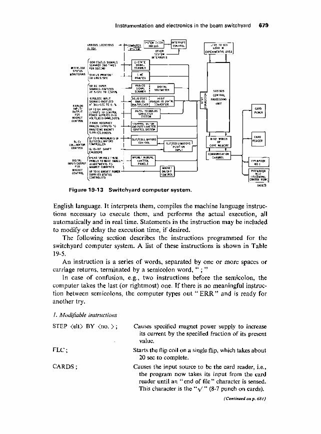
The entire computer system, including the slit and collimator controlsystem, is shown in Fig. 19-13.
Control of the slits and collimators is a complex task involving a separatesystem. The computer can control them through the slit/collimator (S/C)computer control unit, a portion of the S/C control system. The entire systemwill be described later.
Communications between the operator and the computer are accomplishedeither directly by typing the instruction on the typewriter, or by punchingthe instructions on IBM cards and reading the cards into the computer. Theexecution of the instructions is accomplished through the use of the " 925system language," the source language for a real-time compiler which isresident in the computer at all times. The real-time compiler reads instruc-tions from the typewriter (or card reader) on-line and in what is essentially
Instrumentation and electronics in the beam switchyard 679
INTERLOCKSTATUS
INPUT/OUTPUT
FORMAGNETCONTROL
SLIT/COLLIMATOR
CONTROL
DIGITALNPUT/OUTPUT
FORMAGNETCONTROL
H BSY
1008 STATUS SIGNALSSCANNED 360 TIMES —PER SECOND
20 LINES/SEC
'50 D.C. INPUTSIGNALS-DIGITIZED ~~AT 5/SEC TO 0005%
16 PULSED INPUTSIGNALS-DIGITIZED —
UP TO 64 ANALOGOUTPUTS TO CONTROL _POWER SUPPLIES'.O-IOVOLTS.IOOO OHMS, 0.05%
2 HIGH ACCURACYANALOG OUTPUTS TO —ANALYZING MAGNET
>SUPPLIES,0.005%
EJP TO 16 MOVEMENTS OF -SLIT/COLLIMATORS:ONTROLLED
6,10-BIT SHAFTiNCOOERS
'OPERATOR USES THESEPANELS TO MAKE SMALL-ADJUSTMENTS TOMAGNET CURRENTS
t~3
-....
U D T C D [SYSTEM CLOCK I h N T E R R U P T l
SYSTEM 1INTERRUPTS
2-STATE
SCANNER
PRINTER
SCAGNNN4ELR ! VOLTMETER
ISOLID STATE ]1 i-| ANALOG IANALO
HL
1-
DIGTAL TO ANALOGCONVERTER
SYSTEM
STEPPING MOTOR
CONTROL
MAGNET MANUAL
PANELS
SUPPLIES STATUS
4 BIT
- — SLIT/COLLIMATORSPOSITION —
MAGNET
CONTROL
J
SDS925
CENTRAL
PROCESSING
UNIT
I
8192 WORDSOF
CORE MEMORY
* »COMMUNICATION
CHANNEL
Figure 19-13 Switchyard computer system.
English language. It interprets them, compiles the machine language instruc-tions necessary to execute them, and performs the actual execution, allautomatically and in real time. Statements in the instruction may be includedto modify or delay the execution time, if desired.
The following section describes the instructions programmed for theswitchyard computer system. A list of these instructions is shown in Table19-5.
An instruction is a series of words, separated by one or more spaces orcarriage returns, terminated by a semicolon word, " ; "
In case of confusion, e.g., two instructions before the semicolon, thecomputer takes the last (or rightmost) one. If there is no meaningful instruc-tion between semicolons, the computer types out " ERR" and is ready foranother try.
1. Modifiable instructions
STEP <elt> BY <no. > ;
FLC;
CARDS;
Causes specified magnet power supply to increaseits current by the specified fraction of its presentvalue.
Starts the flip coil on a single flip, which takes about20 sec to complete.
Causes the input source to be the card reader, i.e.,the program now takes its input from the cardreader until an " end of file " character is sensed.This character is the "V " (8-7 punch on cards).
(Continued on p. 681)
680 R. A. Scholl et al.
Table 19-5 List of computer instructions
Modifiable instructions—clauses may be added.SET BOX1 -(no.);STEP BOX1 BY (no.);TOLSCAN BOX1 ;TOLSCAN BOX1 A=(no.>;OUTPUT BOX1 ;RECORD BOX1 ;SET (elt>= (no.);STEP (elt) BY (no.);TOLSCAN (elt);TOLSCAN (elt) A = (no.);OUTPUT (elt);RECORD (elt);SEND (string);TIME;CLOCK ((time));CARDS;FLC;
Fixed instructions—all clauses are ignored.SCALE (elt) BY (no.);KILL (label);TUNE (elt) BY (no.);TUNE ALL BY (no.);CLEAR;RESET-(no.);
Instrumentation and electronics in the beam switchyard 681
OUTPUT <elt> ; Causes current of specified magnet (or width ofspecified slit) to be packaged as output.
RECORD <elt> ; Causes scale factor of specified magnet (or width ofspecified slit) to be packaged as output in a formatwhich is reloadable, i.e., the format is in the 925system language.
SCALE <elt> BY <no. > ; Causes the SCALE factor of the specified magnet tobe loaded with the given number. The assumedunits are kilogauss/(GeV/c). This number unique-ly determines the "focal length" of the quad-rupole and hence all of its focusing characteristics.
SEND <string> ; Causes specified string (note—a space is the de-limiter and hence the string contains no spaces)to be packaged as output.
TIME ; Causes the time to be packaged as output.
CLOCK «time» ; Sets the computer clock to the specified time of day.
Examples :STEP Bl BY .01 ;OUTPUT EFA;RECORD Q10;CARDS ;SEND THIS . IS . A . TEST ;TIME;CLOCK (9:00 MIN);
2. Clauses
Clauses may be added to these instructions to give them flexibility. The types ofclauses are given below. In case of confusion, e.g., two clauses of same kind in asingle instruction, the computer takes the last (or rightmost) one.
TIME CLAUSES. Each of the above instructions causes a single action to take place.This action may be taken at a specific time, repeated at periodic intervals, andstopped at another specific time by adding the following clauses (in any orderappearing anywhere before the final semicolon).
EVERY «time»AT «time»UNTIL «time»
Examples:
AT (9:05MIN) EVERY (15SEC) UNTIL (9:20MIN) STEP Bl BY .01 ;(Causes the current to be increased (by 1 % of its value) every 15 sec until9:20.)
AT (T + 30SEC) EVERY (20SEC) UNTIL (T + 10:30SEC) FLC ;(Will cause the flip coil to begin a flip every 15 sec for 10 min. Time may beexpressed in either HR, MIN, or SEC or PUL (beam pulses).
682 R. A. Scholl et al.
Thus,(9HR)(9:OOMIN)(9:00:OOSEC)(9:00:00:OOOPUL)
all express the same time.)
DESTINATION CLAUSE.
TO <integer>
This clause is used with any of the digital output instructions, that is, with
OUTPUTRECORDSENDTIMETOLSCAN
and directs the output to the specified destination. If there is no destination clause,the program assumes typewriter output. The destinations currently available are
integer destination
1 no dest (i.e., ignore the output)2 TWR3 card punch4 Link
Example:
AT (9:05:20SEC) EVERY (20SEC) UNTIL (9:20:20SEC) OUTPUT BlTO 3(Causes the current in Bl to be punched on cards every 20 sec, but 20 secbehind the execution time of the previous example.)
LABEL CLAUSE. Each of the above instructions may be given a label by the user, sothat it may be singled out by the computer later (to be deleted or related to the out-put produced). Instructions without a label clause are implicitly given the label"XX." The label clause
<label> :
may appear anywhere before the final semicolon.
Example:
LABL : EVERY (1 MIN) OUTPUT ADUM ;(Causes ADUM current to be printed on the typewriter every minute indefin-itely.)
3. Fixed instructions
The instructions below ignore any clauses and will be executed just once.
KILL <label> ; Kills the instruction having the specified label.
SET <elt> = <no.> ; Set magnet current (or slit width) to specified value.
Instrumentation and electronics in the beam switchyard 683
Examples:KILL LABL;
SET EFA = 4.5 ;
TUNE ALL BY 0.01
SET BOX1 = 18.0
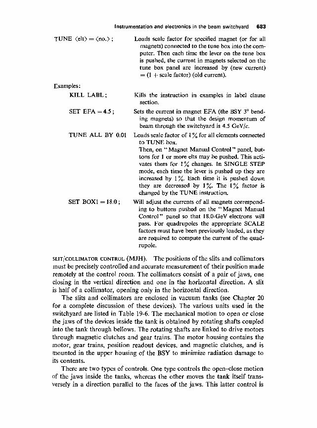
TUNE <elt> = <no.> ; Loads scale factor for specified magnet (or for allmagnets) connected to the tune box into the com-puter. Then each time the lever on the tune boxis pushed, the current in magnets selected on thetune box panel are increased by (new current)= (1 + scale factor) (old current).
Kills the instruction in examples in label clausesection.
Sets the current in magnet EFA (the BSY 3° bend-ing magnets) so that the design momentum ofbeam through the switchyard is 4.5 GeV/c.
Loads scale factor of 1 % for all elements connectedto TUNE box.Then, on " Magnet Manual Control" panel, but-tons for 1 or more elts may be pushed. This acti-vates them for 1 % changes. In SINGLE STEPmode, each time the lever is pushed up they areincreased by 1 %. Each time it is pushed downthey are decreased by 1%. The 1% factor ischanged by the TUNE instruction.
Will adjust the currents of all magnets correspond-ing to buttons pushed on the " Magnet ManualControl" panel so that 18.0-GeV electrons willpass. For quadrupoles the appropriate SCALEfactors must have been previously loaded, as theyare required to compute the current of the quad-rupole.
SLIT/COLLIMATOR CONTROL (MJH). The positions of the slits and collimatorsmust be precisely controlled and accurate measurement of their position maderemotely at the control room. The collimators consist of a pair of jaws, oneclosing in the vertical direction and one in the horizontal direction. A slitis half of a collimator, opening only in the horizontal direction.
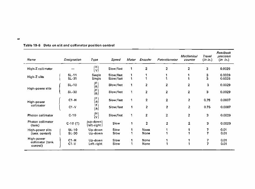
The slits and collimators are enclosed in vacuum tanks (see Chapter 20for a complete discussion of these devices). The various units used in theswitchyard are listed in Table 19-6. The mechanical motion to open or closethe jaws of the devices inside the tank is obtained by rotating shafts coupledinto the tank through bellows. The rotating shafts are linked to drive motorsthrough magnetic clutches and gear trains. The motor housing contains themotor, gear trains, position readout devices, and magnetic clutches, and ismounted in the upper housing of the BSY to minimize radiation damage toits contents.
There are two types of controls. One type controls the open-close motionof the jaws inside the tanks, whereas the other moves the tank itself trans-versely in a direction parallel to the faces of the jaws. This latter control is
Table 19-6 Data on slit and collimator position control
Name
High-Z collimator
High-Z slits
High-power slits
High-powercollimator
Photon collimator
Photon collimator(tank)
High-power slits(tank control)
High-powercollimator (tankcontrol)
Designation
—
( SL-11| SL-31
f SL-10
{ SL-30
f C1-H
i C17V
C-10
C-10 (T)
/ SL-10I SL-30
\ C1-HC1-V
Type
(H)I v|
SingleSingle
IR)\n>IC\
IR}IS)IS)(vH)
(up-down){left-right |
Up-downUp-down
Up-downLeft-right
Speed
Slow/fast
Slow/fastSlow/fast
Slow/fast
Slow/fast
Slow/fast
Slow/fast
Slow/fast
Slow
SlowSlow
SlowSlow
Motor
1
11
1
1
1
1
1
1
11
11
Encoder
2
11
2
2
2
2
2
2
NoneNone
NoneNone
Potentiometer
2
11
2
2
2
2
2
2
11
11
Mechanicalcounter
2
11
2
2
2
2
2
2
11
11
Travel(in in.)
3
33
3
3
0.75
0.75
3
3
77
77
Readbackprecision(in in.)
0.0029
0.00290.0029
0.0029
0.0029
0.0007
0.0007
0.0029
0.0029
0.010.01
0.010.01
Instrumentation and electronics in the beam switchyard 685
required to extend the life of the jaws by changing and thus extending thebeam interaction area. The jaws can be controlled at variable speeds, thetanks at only one speed.
The 16-ft long jaws of the high-power (2-MW) collimator C-l and thehigh-power slits SL-10/SL-30 require two independent drive mechanisms, oneat the front end of the jaws and one at the rear. Magnetic clutches are requiredto switch over from high drive speed to low drive speed.
The slit and collimator jaw position is read back digitally by means ofshaft encoders. In addition, potentiometers are provided to back up theencoders and to give an analog jaw position signal for readout in the acceler-ator control room.
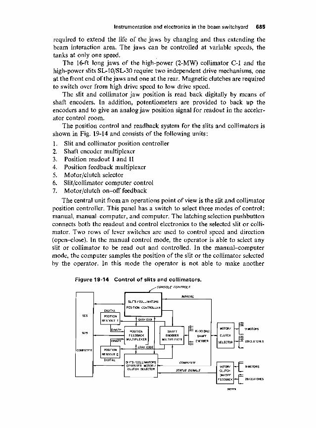
The position control and readback system for the slits and collimators isshown in Fig. 19-14 and consists of the following units:
1. Slit and collimator position controller2. Shaft encoder multiplexer3. Position readout I and II4. Position feedback multiplexer5. Motor/clutch selector6. Slit/collimator computer control7. Motor/clutch on-off feedback
The central unit from an operations point of view is the slit and collimatorposition controller. This panel has a switch to select three modes of control:manual, manual-computer, and computer. The latching selection pushbuttonconnects both the readout and control electronics to the selected slit or colli-mator. Two rows of lever switches are used to control speed and direction(open-close). In the manual control mode, the operator is able to select anyslit or collimator to be read out and controlled. In the manual-computermode, the computer samples the position of the slit or the collimator selectedby the operator. In this mode the operator is not able to make another
Figure 19-14 Control of slits and collimators.-CONSOLE CONTROLS
SDS
925
COMPUTER
DIGITAL
POSITION
READOUT I
[BINARY^
|BINARY~
POSITION
READOUT n
DIGITAL
SLITS/COLLIMATORS
POSITION CONTROLLER
PCS
FEECMULTIF
GRAY CODE
TIONBACK
LEXER
SLITS /COLLIMATORCOMPUTER MOTORCLUTCH SELECTOR
MANUAL
S
ISHAFT
ENCODERMULTIPLEXER
1I
F 16 (10 Bits)
~-\ SHAFT
L- ENCODER
COMPUTER
STATUS SIGNALS
MOTOR/
CLUTCH
SELECTOR
MOTOR/CLUTCH
ON/OFF
FEEDBACK
— J 9 M O
—
— T~
686 R. A. Scholl et a/.
selection until the computer has had a chance to store the previous settinginto its memory. In the computer control mode, the operator can selectivelycontrol any slit or collimator through the use of the system program languageon the typewriter or through the punch-card reader. The computer thenmakes the necessary decisions required to set the slits or the collimators asspecified by the program.
The slit and collimator position controller becomes disabled, in themanual and manual-computer modes, if 3 min have elapsed since the lastchange was made by the operator. The shaft encoder multiplexer containssixteen input channels and two output channels. Each input channel is con-nected to one shaft encoder and the output channels are connected to positionreadouts I and II, respectively.
The position readout devices I and II receive position information ingray code from the shaft encoder multiplexer. The readout devices convertthe 10-bit gray code information into binary form, then from binary into8421 BCD-code,8 and finally from 8421 BCD into a decimal display. The10-bit binary information is sent to the position feedback multiplexer.
The position feedback multiplexer, under computer control, transfers16 bits of data into the computer memory. Ten of the bits originate in one ofthe readout devices, whereas 6 bits represent the device code.
The motor/clutch selector receives a control command from either theS/C position controller or the S/C computer control, and controls the appro-priate clutches and motor accordingly.
The logical design of the S/C computer motor/clutch selector is such thatthe computer is able to select any device and to change the speed and directionof the device. Basically, the S/C computer motor/clutch selector works asfollows.
A control word, which contains 1-bit read/control, 6-bit slit/collimatordevice code, 2-bit speed code, and 2-bit open/close code, is sent by the com-puter to the S/C computer motor/clutch selector. Once the S/C computermotor/clutch selector receives the control word, it decodes the words. If thefirst bit (read/control) is a zero, then the S/C computer motor/clutch selectorallows the computer to sample the S/C position feedback multiplexer. How-ever, if the first bit is a 1, then the S/C computer motor/clutch selector selectsthe slit or collimator, and waits for an acknowledge signal from that slit orcollimator. If the signal returns, it sends the next control command to turnone of the two speed clutches on, and waits for the second acknowledgesignal from that speed clutch. Finally, if the clutch signal returns, it sends asignal to turn the motor on. If the motor is turned on, then the S/C computermotor/clutch selector sends a signal to the computer indicating that every-thing is set, and the computer will proceed to sample the S/C position feed-back multiplexer. Suppose, after the computer has sampled a few times, itdecides to make a change. The computer would then send another word to theS/C computer motor/clutch selector. The S/C computer motor/clutch selectorthen, in turn, stops the motor, changes speed if required, changes motor
Instrumentation and electronics in the beam switchyard 687
direction if required, and informs the computer that it has made the change.No matter what signal the S/C computer motor/clutch selector sends out, italways waits to receive a return acknowledge signal from the clutches or themotors. If no signal returns within -J- sec, then the S/C computer motor/clutchselector will send a malfunction interrupt to the computer. The computerwill inform the operator.
The motor/clutch on/off feedback provides the S/C computer motor/clutch selector with the necessary information for sequential operation, andalso provides the operator with a lamp display showing which clutches andmotors are in use.
The entire slit and collimator position control and readout consists ofthirteen chassis. The function of each chassis is described in detail by Hu.9
19-3 Interlock system—equipment protection (RAS)
In the accelerator, all the interlaced beams traverse a common beam channel—the accelerator waveguide. For this reason if an interlock action formachine protection is sensed, there is usually no way to detect which of thebeams "tripped" it, and all beams must be shut off. These interlaced beamsare separated by the pulsed magnets in the BSY, however, which send themto different experiments in widely separated end stations through separatebeam channels. This separation allows the machine protection system in theBSY to assume an added flexibility by turning off the beam which trippedan interlock, leaving the others on and their associated experiments stillrunning. This flexibility is desirable not only to avoid interruption of experi-mental time on the unaffected beams but also to allow one experiment to runeven if others have been disassembled and their interlock chains broken.
In order to achieve true separation of interlocks, the beams must beseparated; this is because the slow nature of many of the sensors (e.g., tem-perature sensors—response time « 30 msec) precludes distinguishing betweentwo beams only 2.8 msec apart in time and because many interlock functions(e.g., water cooling of protection collimators) are necessary if any beam ison. This separation of the beams is a trickier proposition than one might firstimagine. Although it is true that the pulsed magnets will (barring failure)separate the beams, they must also always send the right beam to the rightplace. Suppose the beams are numbered 1 through 6; then if the interlocksystem is wired to expect beam 1 in the A-analyzing channel, beam 1 will beturned off in the event of water flow failure to slit SL-10, for example. Sup-pose now that by accident beam 2 enters the A-beam channel, and waterflow stops in the slit. The system would turn off beam 1, leaving beam 2 tocontinue to run, perhaps damaging the slit.
To provide some protection against accidents of the above type, one ofseveral techniques can be adopted. For example, the interlocks could be wiredto the switches for the pulsed magnets so that they would always shut off thebeam programmed to come into their channel. This is quite complicated,
688 R. A. Scholl et at.
because the direction and magnitude of deflection is a function of the polarity,number, and setting of the pulsed magnets as well as the sign of the chargeof the particle. In addition, the emergency magnets B-l and B-2 can be usedin lieu of (or even conceivably in conjunction with) the pulsed magnets. Also,this scheme would not protect against failure of the deflection magnet sys-tems. Alternatively, a set of switches could be provided, indicated desiredbeam " destinations " and the interlock system could inspect the actual beamgeometry (as measured by the various current toroids and ion chambers inthe BSY), the beam could be turned off if agreement were not achieved oneach beam pulse. If this same set of switches were to "connect" the interlocksystem to the beam shutoff network, then the interlock circuits would essenti-ally be comparing the actual beam geometry with the one protected. Thissecond method is the one employed in the BSY summary interlock; it iscalled "errant beam" protection. In the above example, if beam 2 enteredthe A-beam channel, the interlock system would detect this condition bynoting a current in 1-10 at the wrong time and would shut off all beams untilthe problem was corrected. Correction could be made either by changing the"geometry selector" so that beam 2 could enter the A channel (the waterflow loss in SL-10 would then shut off beam 2 also), or by readjustingpulsed or emergency magnets so that beam 2 could not enter the A channel.
In addition, the interlock system in the BSY must be switchable to handleexperimental changes. That is, not all interlocks are used in each of the severalpossible beam configurations; indeed, some of the interlock conditions aremutually exclusive. Thus, whole areas of the BSY interlock system can beswitched out at will by the operator; the summary circuits inspect the con-ditions that allow the selection, and if at any time they are not satisfied, thebeams are switched off.
Electronics
The summary circuit for the BSY inspects the beam conditions selected bythe selection circuits on a pulse-to-pulse basis and provides the permissivepulse to the injector circuits, the pattern interlock signals to the CCR, and thenecessary status signals to the BSY operators. The permissive pulse andpattern interlock circuits are described fully in Chapter 21, and will only betouched on here.
The permissive pulse gates the injector trigger, and thus if it is absent thebeam will be inhibited. It is generated on a pulse-to-pulse basis in the switch-yard summary circuits when the switchyard is operating. The acceleratorgenerates its own permissive pulse for accelerator tests (see Chapter 21). Itis this signal which allows the beam to be turned off immediately if necessary.There is no time lag involved. However, since the pulse involves only theinjector, the klystrons don't "know" there is no beam, and stay on in the"accelerate" mode. Therefore, any stray electrons ("dark current") will beaccelerated and produce a small but nonzero beam in the switchyard. The
Instrumentation and electronics in the beam switchyard 689
pattern interlocks have an inherent one-pulse delay—they always allow onepulse to be produced after detection of the fault condition. They, however,remove the accelerate triggers from the klystrons and, thus, reduce the darkcurrent to negligible values. A disadvantage (in addition to the delay) of thepattern interlocks is that the triggers to the BSY equipment and experimentalareas are also removed. These two interlock methods are used in conjunctionwith one another as the situation requires.
The summary circuits for the BSY interlocks work in the following way.The A-beam interlocks are gated by the A-beam pattern (as selected by the"geometry selector"); the B-beam interlocks are gated by the B-beampattern, and so on. The resultant signals are combined (OR'ed) and gatedby the common beam interlocks (those signals from sensors in the areawhere the beams share a common beam channel, i.e., before the pulsed mag-nets). The result is an ac signal which, when gated by a 360/sec trigger at theproper delay time, provides the permissive pulse generator with a trigger.Thus a permissive pulse is generated if either the A-beam is OK when the Apattern pulse is "due," or the B-beam is OK when the B pattern pulse is"due," or the C-beam is OK when the C pattern pulse is "due," and so on,and the common gate is OK. The errant beam detector consists of a flip-flopthat is actuated if a current is detected in its associated toroid or ion chamberwhen there is no pattern signal for that area. There is one flip-flop for each beamarea. The outputs of these flip-flops are connected to the COM MON beam gate.
After most interlock faults, relays in the selector circuits latch out andkeep the beam off until reset. These relays do not drop out for certain "sup-pression functions," such as the pulsed magnet interlock or beam holdduring profile monitor movement, to avoid excessive loss of beam time dueto repeated resets. Normally, the pattern interlock signal is broken whenthis relay drops out, but for those cases where loss of triggers cannot betolerated, a switch is provided that maintains a steady pattern interlock signalindependent of the state of the summary circuits. Also, two signals are accep-ted from each experiment in addition to the interlock circuits. These twosignals come from switches in the experimenter's setup. One "suppresses"the beam; that is, it removes his permissive pulses from the permissive pulsetrain without either dropping out the latch relay (which would require con-trol room reset) or interrupting the pattern interlock circuits (which wouldremove his triggers). The other breaks the pattern interlock circuit withoutdropping out the latch relay. The latter interrupts the beam and removes thetriggers on that pattern. Each experimenter can individually suppress hisown beam and triggers without affecting the other experiments.
lonization chamber interlocks
A few beam pulses at maximum beam power may damage a vacuum chamberor a protection collimator. Since thermal sensors are too slow to detectinstantaneous local temperature changes, ionization chambers have been
used because of their quick response for these purposes. Ionization chambershave the advantages of being simple in construction, easy to make radiation-resistant, and of operating physically independently of the equipment to beprotected. Their disadvantages are (1) they saturate easily, (2) they are verysensitive to geometrical arrangement with respect to the radiation source,and (3) they are somewhat difficult to calibrate.
The ionization chambers used in the switchyard (Fig. 19-15) consist of anumber of parallel aluminum plates with ^-in. spacing connected alternatelyto a signal lead and a high-voltage lead (300 V). The welded stainless steelhousing contains helium at atmospheric pressure. The active volume is1.3 liters. The output signal from the ion chamber is roughly proportional tothe power of the absorbed beam. For the protection collimator shown inFig. 19-15, the charge collected by the chamber is of the order of 10~10 C/Jof absorbed beam in the protection collimator. Thermometers at the inletand outlet of the cooling water for the protection collimator and a waterflowmeter make it possible to calculate the absorbed beam power directlyand can be used to calibrate the ionization chambers. The ionization cham-bers do not saturate if a pulse of a 2-MW beam hits the protection collimator.
Two long, coaxial, ionization chambers are used in the switchyard toprotect long drift sections in the vacuum pipe. These coaxial chambers consistof lengths of Andrews Heliax If-in. coaxial cable filled with helium (or argon).A positive high voltage is applied to the inner conductor; the charge iscollected from the inner conductor through a capacitor.
Instrumentation and electronics in the beam switchyard 691
A gas flow system10 delivers continuously a small flow of helium slightlyabove atmospheric pressure to the ionization chambers.
The gas is supplied by a double bank of twelve bottles with automaticchangeover. After a 20-psi regulator, the supply line divides into four branches;three branches supply the ion chambers and the fourth branch suppliesgas for the Cerenkov cells.
The ion chambers in each branch are connected in series. The flow ismetered and controlled by a needle valve at the input side and monitored onthe return with a low-flow alarm detector. A back pressure regulator in thereturn line maintains a constant upstream pressure (referred to vacuum).
The low-flow alarms operate warning lights but do not inhibit the beam.
IONIZATION CHAMBER DETECTOR CIRCUITS. The pulsed current produced inthe ionization chambers is roughly proportional to the power absorbed inthe protection collimators. The current pulses are integrated in a circuitusing an operational amplifier. The ion chamber is a high impedance currentsource, and, therefore, the input resistor of the integrator has little influenceas long as it is low. It is made equal to the cable impedance (95 ohms) toavoid reflections. The integrator is followed by an adjustable discriminatorand a latching output circuit. The integrator time constant is 0.1 sec, whichis slightly faster than the thermal time constant of the protection collimators.The protection collimators can absorb an average beam power of 20 kW.The trip level at this power absorption level is reached in 100 msec. When theprotection collimator is hit by a beam carrying the full 2-MW beam power,the trip level will be reached about 100 times faster (1 msec), so that the beamwill be switched off before the accelerator will send the next beam pulse(beam pulses are spaced by 2.78 msec).
The output signals from the integrating circuits are terminated in a plugon the rear of each detector circuit. These signals can be connected to a patchpanel for meter readout. The signals are extremely useful for beam-steeringpurposes.
The detector circuit for the long ionization chamber is slightly differentfrom that of other ion chambers because of a different signal polarity.
Some of the ion chambers located near the collimators and dumps arenot used for interlock purposes but for reading the charge intercepted bythese absorbers. A special integrator is built for this purpose with a digitaldisplay reading out the " charge intercepted " by the devices with which theseion chambers are associated.
Thermal protection
A slow temperature rise may occur from the continuous scraping of the beamon the vacuum chamber wall. In places where this is likely to occur, surfacetemperature sensors are mounted on the outside of the vacuum chambers andare arranged to trip the beam if the temperature exceeds a preset level.
692 R. A. Scholl et a/.
The sensors used are 100-ohm platinum resistance elements mounted inplatinum cases and insulated with ceramic material. Radiation exposuretests have shown that these devices are very reliable up to doses of 1013 ergs/g.The sensors are spot-welded to small copper pads which are mounted inmany cases against the vacuum chamber with a fitting that allows easy re-placement. In other cases the sensors are an integral part of a device, suchas those on a magnet chamber.
In addition to vacuum chamber surface temperature measurements,water temperature measurements are made on the cooling water supply andreturn line of slits, collimators, water-cooled vacuum chambers, and dumps.In areas where the radiation levels are very high and where measurementshave to be made in the radioactive cooling water lines, a stainless steelthermal well is welded into the pipe at each measuring location and a radia-tion-resistant immersion sensor is screwed into the well. These devices havebasically the same element as the surface sensor, namely 100-ohm platinumresistance wire, ceramic-insulated, but in this case it is in a stainless steelhousing with an integral electrical receptacle. Connection is made throughstainless steel-jacketed magnesium oxide-insulated cables.
Where the environment is less severe, similar but slightly less expensivesensors are used as direct immersion devices with no thermal wells. Theelectrical connections are made through fiberglass-insulated cables.
TEMPERATURE DETECTOR CIRCUITS. The two basic temperature detector inter-locks circuits are an absolute circuit (measuring temperature at variouslocations on vacuum chambers, etc.) and a differential circuit (comparinginlet and outlet temperatures of the cooling water in various beam-absorbingdevices). Each of the differential resistance thermometers is connected in onearm of a bridge circuit. The absolute temperature interlock circuit uses afixed 100-ohm resistor in the second arm of the bridge. The bridge current islimited to 5 mA to prevent self-heating. A 5-mA current results in a sensitivityof2mV/°C.
The trip circuit uses a magnetic differential detector. This unit consists ofa magnetic current-to-polarized-voltage pulse converter followed by a solidstate on-off output stage. The trip level is set by adjusting the bias of themagnetic converter.
The input impedance of this circuit is 2 kohms, which results in a tripaccuracy of about 1°C, which is adequate for this application.
An output signal from each resistance thermometer is also brought to apatch panel, which makes it possible to measure the various temperatures bymeans of a three-digit digital temperature readout.
To increase reliability, a test circuit is built which tests the electronics ofthe temperature detector circuits and the ion-chamber detector circuits. Thistest circuit checks the tripping action of the detectors as well as the con-tinuity of the cabling system. The test is done automatically after each beamshutoff, but can also be started manually or on a programmed basis.
Instrumentation and electronics in the beam switchyard 693
Secondary-emission foil signals
The interlock circuit for the SEM devices has been described previously. Itis made very flexible to allow for changes that may be required after experi-ence is gained with high-power beams.
Pulsed magnet interlock
A special interlock circuit has been built for the pulsed magnets. It holds thebeam pulse if the magnetic field has not reached the proper value shortlybefore beam injection. A block diagram of this circuit is shown in Fig. 19-16.
When the modulators for the pulsed magnets receive a trigger signal(approximately 416 //sec before beam time), a large transient voltage appearsacross the pickup coils. This transient is detected by the start circuits, whichbegin the timing of a 203-//sec delay circuit. Triggers are injected into thestart circuit to prevent an output if the modulators fire too early or toolate. The delay, in turn, actuates a gate generator, which produces a 10-/tsecgate, 203 //sec later or 213 //sec before beam time.
While the delay is in progress, the gated integrator is producing a signalwhich is proportional to the J B dl through the pulsed magnets. This signal ispassed through the analog processing circuits, which divide it by ^/2 andinvert it if required by the polarity signals. The resulting processed signal iscompared to a reference voltage. The references are derived from the analyz-ing magnet power supplies and are proportional to the beam energy settingsin the A- and B-beams. When the processed analog signal is equal to thereference, a pulse appears at the output of the comparator. This pulse ispassed through the gating logic, which ensures that the "A" comparator isinspected during "A" patterns and the " B " comparator during " B " patterns.
Figure 19-16 Pulsed magnet interlock.
- PICKUP COIL
PULSEDMAGNETS
(5 IN SERIES)
DEFEATSIGNALS
(PULSES & DC)
STARTCIRCUITS
DELAYCIRCUIT
GATEGENERATOR
694 R. A. Scholl et al.
Since the pulsed magnet current waveform is a sine wave with a period of1666.6 usec, the J B dl will reach 1/^/2 of its peak value in 208 usec. The out-put of the gating circuit is a pulse which occurs when the J B dl reaches 1/^/2of the desired peak value. If this pulse occurs during the 10-^sec gate (i.e.,20 + 5 jusec after the start of the waveform), the output pulse generator isenabled. The pulse generator then produces an output signal 208 /isec beforethe beam injection time. This signal is part of a chain which gives a permissivepulse to the injector.
The defeat circuits shown in Fig. 19-16 allow the beam to be enabledduring tune-up periods (e.g., when a third beam is to be deflected to the tune-up dump while the A- and B-beams are on). The system can be defeated on apulse-to-pulse basis, as required by the above example, or permanently by adc signal.
Differential current interlock
This circuit provides protection against beam deflection errors and will backup the devices discussed in the previous sections. The circuit uses the signalsfrom two current transformers. One transformer is located in the commonbeam at the beginning of the switchyard and a second one at the end of eachelectron beam. The circuit will produce an interlock signal if less than acertain percentage (say 10%) of the beam arrives at its destination. Thecircuit operates at higher beam currents only; at low currents it switches offautomatically.
Instead of a signal from a second transformer, the circuit may also oper-ate with a signal from other reference sources, such as a dc signal.
19-4 Pulsed bending magnet supplies (ICL)
General
The pulsed magnet power supplies have the capability of energizing themagnets with a field of either direction (for right or left beam deflection) ona pulse-to-pulse basis, at repetition rates up to 360 pulses/sec, and of recover-ing most of the energy at the end of the pulse. The basic circuit used consistsof silicon-controlled rectifiers (SCR) to switch energy stored in a capacitorbank to the magnets and back to the capacitor bank with relatively smalllosses, and a dc supply to recharge the capacitor bank between pulses.
Power supply circuit
The power supply can be divided into three functional blocks: (1) the energystorage capacitor bank with the associated means of regulating the amountof stored energy, (2) the SCR's used to connect the energy storage capacitorbank to the magnet, and (3) the dc charging supply to recharge the capacitor
Instrumentation and electronics in the beam switchyard 695
Figure 19-17 Basic circuit of pulsed powersupply.
bank at the end of the current cycle. The basic circuit of the pulsed powersupply is shown in Fig. 19-17, and the sequence of operation is as follows:
1. A signal is applied to the grid of the series regulator tube (VI) allowingthe dc charging supply to charge the energy storage capacitor bank to thedesired voltage level ; then the grid is biased negative so that the tube is cut off.
2. The SCR switch (CR1) is then triggered, allowing the capacitor bankto discharge into the pulsed magnet (LI). A sine wave of current builds upin the magnet at a resonant frequency determined by the capacitance of thecapacitor bank (Cl) and the inductance of the pulsed magnet (LI). Duringthis time VI is kept cut off so that the capacitor bank is isolated from the dccharging supply, and the voltage across the capacitor bank decreases with acosine wave shape as the energy is transferred from the capacitor bank to thepulsed magnet. When the magnet current reaches its peak value, the voltageon the capacitor bank is zero and all the energy of the system is stored in thepulsed magnet. Because of the relatively high-Q resonant circuit, the magnetnow acts as a source of energy and discharges back into the capacitor bank,charging it to a negative polarity. The current continues to flow throughCR1 until the energy stored in the magnet has been transferred back to thecapacitor bank, at which time CR1 prevents the current from reversing. Thecapacitor bank remains charged to a negative polarity.
3. The second switch (CR2) is then triggered, allowing the capacitor bankto discharge again into the magnet in order to reverse the polarity of thevoltage across the capacitor bank to its original polarity. CR2 conducts untilthe current tries to reverse, when the energy has been transferred from Clto LI and back to Cl, at which time CR2 effectively opens the circuit, leavingthe capacitor bank charged to its original polarity.
4. A signal is again applied to the grid of VI, which recharges Cl tomake up the losses during the previous cycle. When Cl has been rechargedto the desired voltage, VI is biased off and the power supply is ready for thenext beam pulse.
A resonant frequency of 600 cycles/sec between Cl and LI has beenchosen so that the above sequence of operation can be accomplished in lessthan 2.7 msec, thus allowing the pulsed magnets to be pulsed at 360 pulses/sec, the maximum repetition rate of the accelerator. The chosen resonant
696 R. A. Scholl et a/.
frequency of the circuit is a compromise between the peak voltage requiredon the magnet, the time allowed between pulses, the peak recharge currentrequired, and the amount of heating allowed in the magnet.
Operation
Two power supplies are connected to each pulsed magnet, one typicallyconnected such that its capacitor bank is charged to a positive polarity andthe other such that its capacitor bank is charged to a negative polarity, thusallowing a deflection of an electron beam from the accelerator to either theright or left, as desired, on a pulse-to-pulse basis. The power supplies areindependent and their capacitor banks can be charged to different voltages,if desired, allowing beam pulses of different energies from the accelerator tobe deflected to the two experimental areas.
A "command" pulse is sent to the power supply to trigger the SCRswitch only when it is desired to use that power supply to energize the pulsedmagnet for a particular beam pulse. This command pulse is derived from theoperational pattern signal of the accelerator. In order to assure that theenergy storage capacitor bank is kept charged to the desired voltage level, a" recharge " pulse is sent to each power supply and applied to the grid of theseries regulator tube at a constant 360-pulses/sec repetition rate. This re-charge pulse is derived from the accelerator clock signal.
Energy storage capacitor bank
The energy storage capacitor bank is made up of several pulse capacitors inparallel to give a total capacitance of 32 /^F as required to obtain a 600-cycles/sec resonant frequency with the pulsed magnet inductance of about 2.2 mH.The capacitors are built with a polyethylene dielectric and silicon fluidimpregnant in order to achieve a low-temperature coefficient of capacitance.Changes in the capacitance of the bank will result in a change in the resonantfrequency and, hence, would require a change in the peak voltage requiredto give the desired peak current in the magnet. The cases of the capacitorshave water-cooling tubing soldered to them, through which temperature-regulated water is circulated to eliminate variations due to changes in ambienttemperature.
Series regulator tube
The series regulator tube (VI) is a transmitting-type vacuum tube (3W5000)which is capable of supplying the required peak charging current at a reason-able tube drop and of withstanding the high voltage impressed between thefilament and plate during the magnet current cycle. During the period avail-able for recharging the capacitor bank, the grid is driven positive about150 V until the desired voltage level on the capacitor bank has been reached
Instrumentation and electronics in the beam switchyard 697
at which time the grid is driven negative about 2500 V to cut the tube off.The tube is kept cut off during the rest of the time until the next rechargetime period. The capacitor bank can be charged to any desired voltage up to3000 V by the series regulator tube and the associated voltage regulationcircuitry. The circuitry is designed to regulate to 0.1 % of the desired voltagebetween the values of 1500 and 3000 V dc and regulates very well as low as afew hundred volts.
Silicon-controlled rectifier switch
The silicon-controlled rectifier (SCR) switches CR1 and CR2 are each madeup of eight, type CIS IP, SCR's connected in series. These SCR's have avoltage rating of 1000 V dc and a current rating of 235 A rms. Each SCRswitch conducts for one-half of the sine wave magnet current cycle. Themaximum design value of peak current through each SCR switch is 316 A,the corresponding rms current is 122 A, and the average current is 61 A.The SCR gate pulses are supplied from a pulse transformer having a separatewinding for each SCR.
Dc charging supply
The dc charging supply is a solid-state three-phase rectifier power supplyoperating from 470-V, 30, ac line voltage. The ouput voltage is constant atabout 4000 V dc.
19-5 Pulsed steering magnet supplies (ICL)
The power supplies used with the pulsed steering magnets are of the samedesign as those used with the pulsed bending magnets. They differ only in thatthey have smaller ratings on peak current and voltage and have reversingrelays built in to reverse the polarity of the voltage on the energy storagecapacitor bank when the output current is reduced to zero. The supplies aredesigned to supply a peak current of 23 A into the steering magnet inductanceof 18 mH. The energy storage bank capacitance is about 3.2 /^F and themaximum charge voltage is about 1550 V dc. Type 6JE6A vacuum tubes areused as series regulators and the dc charging supply operates from 117-V,10, ac line voltage.
19-6 Dc power supplies (CAH)
The power supplies required for the BSY dc magnets were purchased tosatisfy various performance specifications. These power supplies are alllocated in the Data Assembly Building with copper cables carrying therequired dc current to the respective magnets for an average distance of150 ft. The electrical ratings of these power supplies were chosen to minimize
698 R. A. Scholl et al.
Table 19-7 Beam switchyard dc power supply ratings
Required powerat 25 GeV
Magnet designation
1. A dump B-23, -24, -25, -262. A bend B-1 0 to B-1 7, B-1 003. Q-10 (8-cm quad)4. Q-11 (8-cm quad)5. Q-12 (1 8-cm quad)6. Q-13 (8-cm quad)7. Q-14 (8-cm quad)8. B-1, B-2 (emergency switching)9. Q-20 (8-cm quad)
the number of types which had to be procured. A comparison of the powersupply ratings and the requirement for handling 25-GeV electrons is givenin Table 19-7.
The required power supplies may be divided into four main groupsaccording to use:
1. A-beam dump magnets, 693 kW at +0.25% regulation2. A- and B-beam bending magnets, 582 and 326 kW at +0.01 % regulation.3. Quadrupole and other miscellaneous magnets, 27.5, 55, 120 kW at
+ 0.1% regulation.4. Steering magnets (dc); ten units ranging from 0.18 to 7.2 kW at +0.1 %
regulation.
The main characteristics of each of these groups of power supplies willbe discussed in the following sections.
Instrumentation and electronics in the beam switchyard 699
All of the dc power circuits of the magnet power supplies are designedand insulated so that any point of the system may be connected to groundwithout disturbing the precision of current regulation or causing excessivevoltage gradients. The dc system is then grounded at the point desired,usually at the current monitoring shunt, through a resistance of 10 to 100ohms that serves to limit any ground fault current resulting from an insula-tion failure of some part of the system. The current through this groundingresistor is monitored with an alarm circuit that turns off the power supplyin case of excessive ground currents.
The off and on circuits and control systems in the BSY control room arebased upon 24 V dc; therefore, a special relay conversion panel is requiredto control the 117-V ac interlock circuits of the various power supplies.
The current from each power supply is monitored with a digital voltmeterlocated in the BSY control room. The shunts (100 mV, 1000 A) used formonitoring the A and B bending magnet currents are mounted in a tempera-ture-regulated oil bath to stabilize these measurements. The other magnetsystems use shunts that have a calibration of about 1.2 V at rated current;this higher voltage shunt allows precision current measurements to be madeeven below 10 % of rated output current. They are water cooled for ratedcurrents greater than 100 A.
The regulation system on each power supply system is required to maintainthe output current within specified tolerances even when a 1\ % line voltagetransient is experienced. Fast response against line voltage transients wasspecified to prevent the high-energy electrons from hitting objects in theBSY. Even a single beam pulse wrongly steered can produce enough radiationrelative to normal levels to cause the protection circuits in the BSY to tripand result in lost beam time of several minutes.
The SCR's or diodes used in the main dc power circuits were required tohave a peak-reverse-voltage rating of 2| times the normally expected circuitvoltages. The number of units used in parallel for the specified current hadto be sufficient to allow normal operation with one device disconnectedin each leg of the rectifier circuit without exceeding the manufacturer'sratings.
Transistor banks were required to have fast acting fuses for each powertransistor and diode isolation oh the bases to allow normal operation withup to 10% of the transistors not functioning or shorted.
Motor-driven reversing switches were required on all of the BSY powersupplies to allow easy changing of the magnet polarity for handling either anelectron or a positron beam. These switches also permit easy degaussing ofthe magnets.
Reverse diodes were installed across the dc circuits ahead of the reversingswitches to protect each of the systems against open circuits from blownfuses in the SCR or transistor circuits. A 10-^F capacitor is connected acrossthe magnet terminals to protect the magnet against voltage transients whenthe reversing switches operate at currents less than 10 A.
700 R. A. Scholl et al.
Magnet impedances
The mechanical construction of the magnets used in the BSY is described inChapter 18. Except for the pulsed magnets, the iron yokes or return paths ofthese magnets are solid (not laminated); therefore, the inductance of the mag-net will vary as a function of frequency. Table 19-8 shows the calculated low-frequency inductance (frequency less than 0.001 Hz). In general the lag inac current versus the ac voltage applied to a magnet will not exceed 70° forfrequencies less than about 2000 Hz, and the impedance will be less thanone-tenth of that calculated using the low-frequency inductance for frequen-cies >5 Hz, because of the lossy nature of the solid iron cores.11
The location of the energizing coils of these magnets relative to the gapis such that the percent field variation is about equal to the percent currentvariation for frequencies less than 5 Hz and is only about a factor of 10 downat the ripple frequencies of 360 Hz.
Dump magnet power system
Four magnets (B- 23, -24, -25, and -26) are connected in series and poweredfrom a single power supply to direct either the electrons or positrons beingguided through the A bending system into a water-cooled dump. This dumpis used during photon beam experiments and for other special cases to preventthe primary beam from entering the end station A experimental areas.
The power supply is fed from a 480-V, three-phase power line and con-sists of two three-phase bridge rectifiers using SCR's with separate LC filters(20-Hz cutoff), connected in series to provide the rated output with twelve-phase ripple. A single plate transformer is used with a delta primary andwater-cooled Y and delta secondary windings.
The power supply uses a transductor as the current sensing element inthe slow loop portion of the current regulation system. A voltage feedbackloop sensing ahead of the main LC filters (20 Hz cutoff) is combined with theslow current loop to give a fast response against sudden line voltage changes.
Table 19-8 Calculated magnet inductances"
Magnet system
1. A dump magnets (4 in series)
2. A bending magnets (9 in series)
3. 8-cm quads
4. 18.5-cm quads
5. B-1 and B-2 in series
6. B-beam magnetic slit (B-36 or B-37)
Calculatedinductance
(H)
0.36
1.5
0.04
0.05
0.17
0.03
Timeconstant
(sec)
1.0
1.80.5
0.4
1.7
0.009
' Frequencies less than 0.001 Hz.
Instrumentation and electronics in the beam switchyard 701
The variable phase triggers for control of the SCR's are Schmidt triggersderived from comparison of a variable dc voltage and a well-filtered sinewave from the 60-Hz ac line voltage.
The A bending magnet power system
The A bending magnet system used to guide the accelerated particles throughthe BSY to the end station A experimental hall consists of eight of the 3°bending magnets in the switchyard and one reference magnet of the samedesign, located in the Data Assembly Building (DAB). These nine magnetsare connected in series with the power supply to guarantee that all the mag-nets have an identical history of variations of current. (See Fig. 19-18.)
Earlier investigations of the reproducibility of a magnetic field of similarmagnets12 has shown that they will track if the rate of change of currentthrough all of the magnets is held the same.
The dc power for this magnet system consists of two 350-kW (435-V,805-A) power supplies connected in series with a transistor bank to providea regulation of ±0.01 %. The transistor bank uses 328 transistors connectedin parallel to handle a maximum of 805 A. The bank has a maximum ratingof 53 kW but normally operates at 31 kW (38 V drop). The voltages from thetwo 350-kW power supplies furnishing the main dc power for this system havetheir output voltages controlled with induction voltage regulators by a slowloop servo system that senses the voltage across the series transistor bank;the regulation system maintains approximately 38 V dc across the series
Figure 19-18 End station A bending magnet—powersupply system.
drc
1 10/xF
A x lOOmVX | 1.000 AMPS ,
GROUND-1 TTmni Fn ZCURRENT | d=b °̂°L
NE
TD P
DETECTOR-j TT SHUNT
"f"f CURRENTMONITORING 1 '
^
BIO
Bll
BI2
BI3
BIOO
BI4
BIS
BI6
BI7
-o.STEPPINGMOTOR
( REMOTECONTROL )
702 R. A. Scholl et al.
transistors and maintains the current in the bending magnets within ±0.01 %from 40 to 100% rated current.
The dynamic range of control is from about 10 to 805 A. The current iscontrolled from the DAB control room with a stepping motor drive on amultiturn potentiometer that always changes the current in the magnet at arate of 6 A/sec. This rate was chosen as about the optimum regarding con-venience and reproducibility of the field versus current in the magnet.
The B bending magnet power system
The B bending magnet system uses components similar to the A bendingsystem except that only one 350-kW power supply is required to drive fourbending magnets in the switchyard and one reference magnet in the DAB.The transistor bank for the B side is rated for 35-kW and operates at a normalvoltage drop of 27 V.
Quadrupole and other miscellaneous magnet power supplies
Quadrupole power supplies rated at 27.5 and 55 kW have been provided.They energize magnets of similar impedances but allow for the fact that thebeam optics does not require maximum power to be available for all of themagnets. Power supplies of these ratings are also used to energize othermagnets, such as the emergency magnets B-l and -2, the B-beam switchingmagnets B-36 and -37, and the B-beam pulsed magnet B-38 when the latteris energized with dc (not pulsed) power.
The regulation system of these power supplies is a current-stabilized,voltage-regulated, three-phase bridge, SCR system. The voltage-regulatedsystem is current-stabilized through a slow loop using a transductor as thecurrent sensing element. The voltage regulation part of the system comprises
Figure 19-19 The 27.5- and 55.3-kW quadrupole power supplies.
TRANSOUCTOR
Instrumentation and electronics in the beam switchyard 703
two loops: (1) an SCR regulation system and (2) a shunt transistor bankcarrying about 10% of the rated power supply current to extend the fre-quency response range above the limit of about 10 Hz for the SCR loop(see Fig. 19-19).
The current in these power supplies can be adjusted from the controlroom by either a dc motor driving a multiturn potentiometer or by the useof a digital-to-analog converter. The regulation loop amplifiers have a built-in rate-limiting system that forces the current to change slowly regardless ofthe size of step required by the digital-to-analog converter. This rate limiterhelps prevent overshooting of the current when making step changes in cur-rent with the digital-to-analog converter. The ±0.1 % accuracy required forthese magnets can be attained using only the current vs field relationshipsobtained during magnetic measurement.
Steering magnets
The power supplies for the steering magnets must be easily controlled froma positive current to a negative current with as little perturbation as possibleat the zero current point. Some of the magnets steer in the vertical plane andothers steer in the horizontal plane.
Reversing control is accomplished with reversing switches automaticallyactuated when the stepping motor-driven multiturn potentiometer used forcurrent control approaches its zero position.
This type of control allowed for the minimum size of required powersupply. A lever-type switch is used for the control of the current setting forthese steering magnets.
The reversing switch position and current setting potentiometer controlsare coordinated so that the position of the potentiometer control handleindicates the direction in which the beam will be steered regardless of themagnitude or sign of the current in the steering magnet. Thus, a left positionof a control handle may mean an increase in current in the normal positionof the reversing switch, but it would cause the current to decrease if thereversing switch were in the reverse position.
All these power supplies are regulated with series transistor banks togive good control and stability over a dynamic range of 100 to 1 in current.
Some of the power supplies use a narrow range regulator with a motor-driven variable transformer controlled to keep the regulator in range; otherunits have a fixed power supply voltage with a series transistor bank that canabsorb the total voltage when required to operate at low magnet currents.
A cknowledgments
The authors are deeply indebted to D. A. G. Neet, who headed the Instru-mentation Group responsible for the work herein described from its inceptionuntil September, 1966, when most of the work was completed. He providedthe vital direction and leadership necessary to accomplish a project of this
704 R. A. Scholl et a/.
magnitude in the time required. B. de Raad supplied most of the criteria,calculations, and preliminary development of the monitoring instruments inaddition to several very valuable suggestions on electronics techniques.H. Dijkhuizen and J. Cole designed and developed most of the originalinterlock circuits for machine protection.
References
1 D. Olsen, "Beam Position and Intensity Displays in the BSY," Tech. NoteNo. SLAC-TN-64-92, Stanford Linear Accelerator Center, Stanford Univer-sity, Stanford, California (November 1964).
2 R. S. Larsen, " Design of Beam Position and Charge Monitoring Circuits forthe Stanford Two-Mile Accelerator," Kept. No. SLAC-63, Stanford LinearAccerator Center, Stanford University, Stanford, California (May 1966).
3 D. Olsen, " Design of a Precision Current Integrator for the BSY," Tech. NoteNo. SLAC-TN-65-56, Stanford Linear Accelerator Center, Stanford Univer-sity, Stanford, California (July 1965).
4 B. De Raad, " The Application of Synchrotron Light for Beam Observation inthe BSY," Tech. Note No. SLAC-TN-63-95, Stanford Linear AcceleratorCenter, Stanford University, Stanford, California (November 1963).
5 B. De Raad, " Beam Profile Monitors for the Beam Switchyard," Tech. NoteNo. SLAC-TN-64-77, Stanford Linear Accelerator Center, Stanford Univer-sity, Stanford, California (September 1964).
6 W. Schulz, "A Multipurpose and Variable-Parameter Microspray Gun andTwo of Its Applications at SLAC," Tech. Note No. SLAC-TN-67-3, StanfordLinear Accelerator Center, Stanford University, Stanford, California (January1967).
7 R. V. Pound and W. D. Knight, Rev. Sci. Instr. 21, 219 (1950).
8 M. J. C. Hu, "Binary to BCD (8421) Converter by Modulo 1010 Method,"Tech. Note No. SLAC-TN-65-53, Stanford Linear Accelerator Center, Stan-ford University, Stanford, California (July 1965).
9 M. J. C. Hu, " Beam Switchyard Slit and Collimator Position Control andReadout System," Tech. Note No. SLAC-TN-66-52, Stanford Linear Acceler-ator Center, Stanford University, Stanford, California (December 1966).
10 R. Coombes, "Proposed Gas Flow System for the BSY," Tech. Note No.SLAC-TN-64-91, Stanford Linear Accelerator Center, Stanford University,Stanford, California (October 1964).
11 Gustavo R. Gonzalez and Amedeo Brambilla, " Frequency Dependence of theResistance and Inductance of Solid Core Magnets," Rept. No. CEAL-1019,Cambridge Electron Accelerator Laboratory, Cambridge, Massachusetts(March 1965).
12 C. A. Harris and J. K. Cobb, " Establishing the Magnetic Field of a SolidPole Magnet to within ± 0.01 %," Proc. Intern. Symposium on Magnet Techno!.,Stanford Linear Accelerator Center, September 1965 (H. Brechna and H. S.Jordon eds.), p. 823, CONF-650922, Clearing House for Federal Scientific andTechnical Information, Springfield, Virginia.